design and procedures manual section 11 storm drainage .../media/corporate/files/dou/specs... ·...
TRANSCRIPT

Design and Procedures Manual
Section 11 – Storm Drainage Design Standards

SECTION 11 – TABLE OF CONTENTS
11.1 PURPOSE AND DEFINITIONS ............................................................................................................................. 1
11.1.1 Purpose .......................................................................................................................................................... 1
11.1.2 Definitions ....................................................................................................................................................... 1
11.2 GENERAL REQUIREMENTS ............................................................................................................................. 9
11.2.1 Minimum Standard ......................................................................................................................................... 9
11.2.2 Allowable Depths and Discharge, Minimum Requirements for Design .......................................................... 9
11.2.3 Drainage Facilities in the Combined Storm/Sanitary Sewer System ............................................................ 11
11.2.4 High Ground Water Areas ............................................................................................................................ 11
11.2.5 No diversion of Flows ................................................................................................................................... 12
11.2.6 Maintenance Requirements ......................................................................................................................... 12
11.2.7 City of Sacramento Standard Specifications (CSSS) ................................................................................... 12
11.2.8 Models, Graphs, Charts and Methods ......................................................................................................... 12
11.2.9 Storm Drainage Master Plan ........................................................................................................................ 13
11.2.10 Geotechnical Design Report/Groundwater Information .............................................................................. 13
11.2.11 Phasing of Drainage Facilities .................................................................................................................... 14
11.2.12 Drainage Design Report ............................................................................................................................ 14
11.2.13 Geotechnical Design Report ...................................................................................................................... 15
11.2.14 Geotechnical Monitoring ................................................................................................... 16
11.3 DESIGN RUNOFF/DESIGN CRITERIA ............................................................................................................ 17
11.3.1 Sacramento charts (640 acres and smaller drainage sheds) ....................................................................... 17
11.3.2 Sacramento Method (640 acres and larger drainage sheds) ....................................................................... 18
11.3.3 SSWMM (all drainage sheds) ....................................................................................................................... 18
11.3.4 Rational Method (Less than 100 acre drainage sheds) ................................................................................ 18
11.4 DESIGN OF CONVEYANCE AND STORAGE FACILITIES ............................................................................. 22
11.4.1 General Design Requirements ..................................................................................................................... 22
11.4.2 On-site Facilities .......................................................................................................................................... 22
11.4.3 Design of Conveyance and Storage Components ........................................................................................ 22
11.5 DESIGN OF PIPELINES ................................................................................................................................... 23
11.5.1 Size .............................................................................................................................................................. 23
11.5.2 Velocity ........................................................................................................................................................ 23
11.5.3 Cover ........................................................................................................................................................... 23
11.5.4 Placement .................................................................................................................................................... 23
11.5.5 Minimum Right-of-way Width ....................................................................................................................... 24
11.5.6 Material and Roughness .............................................................................................................................. 24
11.5.7 Removal and Replacement .......................................................................................................................... 26
11.5.8 Access Control ............................................................................................................................................. 26

11.5.9 Conflicts with Sewer and Water Lines .......................................................................................................... 26
11.5.10 Tapping Existing Manholes ........................................................................................................................ 26
11.6 PIPELINES IN LEVEES .................................................................................................................................... 27
11.6.1 General ........................................................................................................................................................ 27
11.6.2 Flowline ........................................................................................................................................................ 27
11.6.3 Discharge Pipe ............................................................................................................................................. 27
11.6.4 Welded Steel Pipe ....................................................................................................................................... 27
11.6.5 HDPE Pipe ................................................................................................................................................... 27
11.6.6 Minimum Cover ............................................................................................................................................ 27
11.6.7 Vacuum release ........................................................................................................................................... 29
11.6.8 Outfall structures .......................................................................................................................................... 29
11.6.9 Erosion Protection ........................................................................................................................................ 29
11.7 MANHOLES ...................................................................................................................................................... 30
11.7.1 Locations ..................................................................................................................................................... 30
11.7.2 Manhole Types ............................................................................................................................................ 30
11.8 DROP INLETS AND GUTTER DRAINS ........................................................................................................... 31
11.8.1 Types of Drop Inlets ..................................................................................................................................... 31
11.8.2 Connections to Manholes ............................................................................................................................ 31
11.8.3 Tributary Flow and Placement ..................................................................................................................... 31
11.8.4 taps to Drop Inlet .......................................................................................................................................... 31
11.8.5 Pass Over Drop Inlet .................................................................................................................................... 31
11.8.6 Gutter Drains ................................................................................................................................................ 31
11.9 OVERLAND RELEASE ..................................................................................................................................... 33
11.9.1 General ........................................................................................................................................................ 33
11.9.2 Private Property ........................................................................................................................................... 33
11.9.3 Multi-Use, Erosion and Protection of Property ............................................................................................. 33
11.10 OPEN CHANNELS .......................................................................................................................................... 34
11.10.1 General Requirements ............................................................................................................................... 34
11.10.2 Channel Design Criteria ............................................................................................................................. 34
11.10.3 Dimensional Limitations .............................................................................................................................. 34
11.10.4 Velocity Limitation ...................................................................................................................................... 35
11.10.5 Channel Curvature Limitation ..................................................................................................................... 36
11.10.6 Manning’s roughness Coefficient ............................................................................................................... 36
11.10.7 Channel Improvement Requirement .......................................................................................................... 36
11.10.8 Access ....................................................................................................................................................... 36
11.10.9 Levees ....................................................................................................................................................... 37
11.10.10 Fencing .................................................................................................................................................... 37
11.10.11 Utility Crossings ....................................................................................................................................... 38

11.10.12 Road Crossings ....................................................................................................................................... 38
11.10.13 Road Crossings RD1000 ......................................................................................................................... 38
11.11 DETENTION BASINS ..................................................................................................................................... 39
11.11.1 General ...................................................................................................................................................... 39
11.11.2 Design Guidelines ...................................................................................................................................... 39
11.11.3 Required Capacity ...................................................................................................................................... 39
11.11.4 Maximum Allowed Discharge into Receiving Waters ................................................................................. 40
11.11.5 Number of Pumps at Detention Basins ...................................................................................................... 40
11.11.6 Low Flow Pumps for Detention Basins ...................................................................................................... 40
11.11.7 Pump Operation at Detention Basins ......................................................................................................... 40
11.11.8 Pump Power Sources ................................................................................................................................ 41
11.11.9 Basin Slope configuration .......................................................................................................................... 41
11.11.10 Groundwater in Detention Basins ............................................................................................................ 41
11.11.11 Clay Liner ................................................................................................................................................. 42
11.11.12 Road Crossings ....................................................................................................................................... 43
11.11.13 Outfall/Inlet Structures ............................................................................................................................. 43
11.11.14 Concrete Low Flow Channel .................................................................................................................... 44
11.11.15 Water Quality of Permanent Pools ........................................................................................................... 44
11.11.16 Fencing .................................................................................................................................................... 44
11.11.17 Landscaping and Irrigation ....................................................................................................................... 44
11.11.18 Maintenance ............................................................................................................................................ 45
11.12 WATER QUALITY ........................................................................................................................................... 47

11-1
SECTION 11 STORM DRAINAGE DESIGN STANDARDS 9/09
11.1 PURPOSE AND DEFINITIONS
11.1.1 Purposes Sections 11 and 12 are the Storm Drainage portion of the Design and Procedures Manual. Section 11 contains general standards and criteria for the planning and design of all storm drainage facilities, specifics for the design and construction of conveyance and storage facilities and for the design and construction of water quality facilities. Section 12 pertains to the design and construction of drainage pump stations. Since the standards and criteria will periodically be updated to address new products and practices, the engineer should get the latest revisions prior to beginning work. The appropriate application of the standards and criteria to specific projects is the sole responsibility of the engineer of record (EOR). It is expected that issues will arise which will not be completely addressed in these two sections, and those issues will require unique solutions by the engineer. The following represents the standards for drainage design and all exceptions to the standards shall be approved by the Director.
11.1.2 DEFINITIONS Whenever the following terms or titles are used in these two sections, the intent and meaning shall be as herein defined: 10 Year Storm: A rainstorm that has a one-in-ten (1:10) chance of being equaled or exceeded in any given year. 100 Year Storm: A rainstorm that has a one-in-one hundred (1:100) chance of being equaled or exceeded in any given year. Angle Point/Grade Change: An angle point is a point of change in horizontal alignment; a grade change is a point of change in vertical alignment. Both are, usually, associated with a pipe (See Break Point).
Break Point: A point of change in horizontal or vertical alignment of a pipe. City of Sacramento Standard Specifications (CSSS): The latest edition of the City of Sacramento Standard Specification for Public Construction. CFS: Cubic feet per second, a measure of the volume of flow over time. Clay Liner: An impermeable clay layer, consisting of on-site excavated material or imported clay material, placed after excavation to line a detention basin, the purpose of which is to prevent ground water intrusion and/or to retain water within a detention basin. A clay liner must

11-2
be carefully designed to prevent displacement due to bouyancy and may be required to be several feet thick. Clay liners may also refer to manufactured clay liners consisting of bentonite and various types of fabrics which are usually installed by over-excavating the basin, placing the liner, and covering it with a layer of fill to prevent displacement or damage. CDD: City of Sacramento, Community Development Department: the City Department that provides entitlements, building permits and inspections, subdivision and other map approvals, and planning functions. City/County Drainage Manual: The latest edition of the “Sacramento City/County Drainage Manual, Vol. 2, Hydrology Standards” developed jointly by the Sacramento County Water Resources Division and the City of Sacramento Department of Utilities. Common Drainage Facilities: For the purpose of public financing of drainage infrastructure, the term “Common Drainage Facilities” shall be defined as follows:
any pipe or other conveyance system whose capacity is equal to or greater than that of a 24" inch diameter pipe, including all appurtenances other than drainage inlets and drain inlet leads; all channels, appurtenances, and Department of Utilities (DOU) level landscaping; all detention basins, water quality basins, appurtenances, and DOU level landscaping; all pump stations, appurtenances, and DOU level landscaping; all property necessary for the maintenance of the above facilities which is not or will not be in a road right of way or other right of way which is dedicated to the public for purposes other than drainage.
Appurtenances for the above common facilities shall include but shall not necessarily be limited to the following:
1. Pipes and other conveyances: manholes, junction boxes, weirs, floodgates, flap gates, and sluice gates.
2. Channels: concrete lining, concrete low flow channels, inlet structures, outlet structures, fencing, access roadways, berms, turnouts, pools, retaining walls, chutes, weirs, floodgates, flap gates, sluice gates, slope protection, and DOU level landscaping.
3. Detention Basins and Water Quality Basins: clay liners, french drains, under- drains, inlet structures, outlet structures, irrigation, low flow channels, weirs, sluice gates, flap gates, access roads, slope protection, fencing or masonry walls, and DOU level landscaping.
4. Pump Stations: Access roads, lay down areas, trash racks, mechanical and electrical systems, control buildings, masonry walls, gates, fencing, telemetry, pumps, outfall pipes and structures, flap gates, sluice gates, lighting, on-site backup power, on-site maintenance equipment, on-site drains, potable water infrastructure, irrigation, and DOU level landscaping.
Community Facilities District/CFD: An instrument to fund public improvements, such as common drainage facilities, using public funds. See “Public Financing,” below. Culvert Drainage Systems: A drainage system consisting of channels or ditches with vehicle and/or pedestrian crossings provided by short sections of pipe or culverts.
11-3
Detention Basin: An excavation, either within the flow path of a channel or piped system (in-line), or connected thereto (off-line), which is positioned to allow for the storage of runoff during a storm, particularly during the peak of a storm, and the release of stored runoff after the peak of a storm. DI: Drop inlet or Drain inlet, a concrete structure with a steel grate used to direct drainage flow from a curb and gutter, via pipe to a manhole. Director: In Sections 11 and 12, “Director” refers to the Director of the Department of Utilities or his designated representative. Do No Harm: The standard for design and construction requiring that all existing affected drainage systems function as well, or better, as a result of the proposed construction, and that there is no increase in flooding or in water surface elevation with negative impacts to individuals, streets, structures, infrastructure, or property. DOT: City of Sacramento, Department of Transportation DOU: City of Sacramento, Department of Utilities DOU Level Landscaping: All landscaping features, seeding, vegetation, planting, irrigation, controllers and the maintenance required for plant establishment, as required to prevent erosion and to provide an environment in keeping with the surrounding neighborhood. The required level of landscaping shall be determined by the Director on an individual project basis. Drainage Shed or Drainage Basin: A geographical area of land over which all runoff flows to a single end point at its perimeter boundary. The City of Sacramento is currently composed of 128 numbered Drainage Basins. Those basins which terminate with a gravity outfall to a receiving water body are designated with a number preceded by the letter G. Drainage Sub-Shed/ Sub-Shed: A smaller drainage shed within a larger drainage shed. Drain Rock: Clean crushed rock of specified size and consistency through which runoff is allowed to flow. Dry Detention Basin: A detention basin which remains dry, with the possible exception of a low-flow channel, until a storm occurs which would otherwise result in flooding of streets and/or property. Such a detention basin lends itself to a variety of other uses. Filter Fabric: A cloth product that may be manufactured to accommodate a variety of purposes, but for the purposes of this Section, it is a product which is designed to prevent the passage of soil particles while allowing the passage of water. Final Map: A map showing a subdivision of five or more parcels for which a tentative and final map are required by the Subdivision Map Act and Title 16 of the City Code, prepared in accordance with the provisions of the Subdivision Map Act and the Title 16 of the City Code, and prepared for recordation in the office of the County Recorder.

11-4
Flow Line Elevation: The bottom most, lowest portion, or invert of a pipe, manhole, drop inlet, detention basin, sump or other structure over which water drains. French Drain: A subterranean, vertical layer of clean crushed rock (drain rock) intended to facilitate the drainage of groundwater from the surrounding soil. Ordinarily a French Drain is constructed by excavating a trench, lining it with filter fabric, and backfilling the trench with drain rock to within a few inches of the surface, then covering the rock with filter fabric, and finally backfilling the trench to the surface with soil. For more efficient drainage, a perforated drain pipe may be placed just above the bottom of the trench and the invert sloped to gravity drain to daylight, a drain inlet, or a manhole. Greenfield Area Drainage Development: A completely new drainage system in a developing area that discharges into an existing drainage system, a pump station or directly into a receiving channel or stream. High Ground Water: A condition wherein the elevation of the groundwater is, at any time, above the invert of the pipe, detention pond, channel, or structure. There are regions in the City of Sacramento that are known to be subject to high ground water conditions, including, but not limited to North Natomas, the Pocket Area and Valley Hi.
Hydraulic Grade Line: The theoretical line describing the water surface throughout a drainage system when not constrained by anything other than atmospheric pressure. It will manifest itself as the actual water surface at any facility open to the atmosphere such as a sump, manhole, DI, channel, or detention basin. Improved Drainage System: An existing drainage system for which a master drainage plan has been completed, necessary improvements have been made to existing drainage facilities, and new facilities have been constructed necessary to satisfy the City Council-approved 10 and 100 year drainage standard. Infill Area Drainage Development: A new drainage system within an already developed area that connects into an existing drainage system. Often the established drainage facilities have been designed based on constant runoff rates (cfs/acre) and are unable to provide the City Council approved standard for flood protection. Infill Site: This term is not used in reference to drainage systems but is included herein to clarify the definitions of similar terms by contrast. The City Code in Section 17.84.020, defines Infill Site as:
A residentially zoned vacant lot which meets all of the following criteria:
A. The lot is surrounded on at least three sides by development consistent with that planned for the surrounding property according to the applicable community plan or is contained within an infill area designated for infill development in the general plan or applicable community plan. An infill area is an area which is surrounded on at least three sides by development consistent with that planned for the surrounding property according to the applicable community plan and for which development would not

11-5
normally occur because of economic or physical site constraints. B. The lot meets the size standards set forth in subsection (B)(1) of this section or the
planning commission has determined pursuant to subsection (B)(2) of this section that the size standards may be exceeded:
1. For lots zoned R-1 and R-2, the lot shall be no more than five acres. For lots
zoned R-1A through R-5 (except for R-2) the lot shall be no more than two acres. 2. The planning commission may grant a special permit pursuant to Chapter 17.212
of this title to exceed the size standards in subsection (B)(1) of this section. 3. The lot has city sewer, water and drainage services or is within a proposed or
existing assessment district for such services. Such services must be capable of serving the proposed development.
Interior Drainage Channel: Any channel that serves areas on the landward side of a levee or a floodwall. Junction Structure/Junction Box: A reinforced concrete structure or box which will accommodate an angle point in a pipe larger than 42" in diameter, the junction of two or more pipes larger than 42" in diameter, or other cases where, in the judgment of the engineer of record, it is required. A Junction Structure is designed to allow smooth flow through with as little head loss as possible and often must be designed to accommodate high groundwater, traffic loads and unusual soil conditions. LAS: Landscape Architect Section of the Parks and Recreation Department (PRD). Levee: An earth embankment used as barrier to protect people and property on the landward side by containing flood waters. Lined Channel: A channel in which a portion or all of its bottom and/or side slopes are covered with a layer of material intended to prevent erosion or seepage. A “Hard Lining” may consist of gunite, shotcrete, soil cement, mortared stone, or reinforced concrete as a protection against erosion. A “Flexible Lining” may consist of natural stone, riprap, gabions, and/or certain fabrics. Low Ground Water: A condition wherein the elevation of the groundwater is never, at any time, above the invert of the pipe, detention pond, channel, sump or structure. Major Riverine Channel: In Sacramento, the channels occupied by the Sacramento River and the American River. Map Conditions: Subdivision Design conditions placed on the tentative subdivision map that must be satisfied prior to recording of the final map. Master Parcel Map: A map that subdivides large tracts of land into smaller parcels for the purpose of selling or otherwise transferring the parcels for further subdivision in accordance with the specified procedures, or for the purpose of securing financing, together with planning and construction of infrastructure elements, but not for the purpose of creating individual residential lots for sale to end-user homeowners, and not for the purpose of allowing construction or other improvements on non-residential parcels.

11-6
Naturalized Channel: A meandering channel with an earth bank, native vegetation and other features which provide for natural habitat and improved water quality, designed to handle the projected flow. Nominal Design Capacity: the performance standard used in master-planning to determine the ability of an existing drainage system to handle calculated runoff. It is obtained by diving the “firm capacity” (capacity with one pump off) of the pump station (cfs) by the service area of the drainage system (acres). Overland Release: A condition where floodwater in a sumped area or depression rises to the low point on the rim of the depression (overland release elevation) and water spills out into an appropriate receiving drainage feature. The spillway is to be placed at such an elevation and location that no structures will be flooded during the 100 year, 10 day storm or the 100 year, 24 hour storm and at a minimum of 1.5 feet below the lowest finished floor elevation. Overland release is required in All Greenfield Development projects. Passover DI: A drain Inlet that is not located at a local low point in the street profile. Whenever gutter flow exceeds the ability of the drain inlet to receive flow, the excess water passes over the DI and continues flowing downstream. To mitigate excess flow, more than one DI may be required in series. Preliminary Design Report: A design planning document that needs to be approved by the Director prior to designing a drainage system. The Preliminary Design Report is used to determine the technical feasibility of serving the area by the proposed drainage system and to identify required right-of-way and costs. Public Financing: A finance tool which allows a public agency (in this case the City of Sacramento) to establish a benefitting district (community facilities district or assessment district) and to sell bonds to pay for the design and construction of public drainage facilities required for development. Various types of bonds are available for the purpose: Mello Roos, 1913, and 1915 bonds. Rational Method: a method of calculating peak runoff flow rate that is the product of the imperviousness of the watershed, the intensity of rainfall and the watershed area. RD1000: Reclamation District No. 1000 was created April 8, 1911 by a Special Act of the Legislature to provide agricultural drainage, flood control and levee maintenance. Situated on flat terrain in northwestern Sacramento in Sacramento County and Sutter County, RD1000 currently maintains approximately 53 miles of levees. The District is bounded on the west by the Sacramento River, on the north by the Natomas Cross Canal, on the east by the Pleasant Grove Creek and Natomas East Main Drainage Canals and on the south by the American and Sacramento Rivers. The stated mission and purpose of RD 1000 is to “operate and maintain the levees surrounding the Natomas Basin and to operate and maintain the internal drainage system to evacuate agricultural and urban runoff.” Release Point: Any location where runoff may be discharged from a sumped (“blocked gravity”) condition.

11-7
Round Corners: The rounded portions of the four points of intersection of two intersecting streets. Each or the four corners in a street intersection is a portion of a circular curve, tangent to the boundaries of the intersecting streets. The round corner includes the construction of asphalt pavement, curb, gutter and sidewalk. The curb and gutter portion of the round corners allow the smooth flow of runoff. A DI often intercepts the flow of runoff at the tangent point of the round corner. Sacramento Method: As described in chapters 3 through 10 of the City/County Drainage Manual, the Sacramento Method is a method of estimating flows from natural, historic, or synthetic storms, as an aid to flood risk evaluation and drainage design. SSWMM: Acronym for the Sacramento Storm Water Management Model, a matched pair of storm simulation programs that are used for flood risk evaluation and drainage design. The first simulation program, called “RUNOFF,” is a hydrology program that converts a time series of rainfall amounts into a time series of runoff flows entering a drainage system at discrete locations. The second simulation program, called “EXTRAN,” is a hydraulics program that routes the incoming flow through the drainage system, and calculates the depth, velocity, and rate of flow in pipes, channels, streets and gutters. Subdivision Design: Subdivision Design includes (1) street alignments, grades and widths; (2) drainage, sanitary sewer, and water facilities and utilities, including alignments and grades thereof; (3) location and size of all required easements and right-of-way; (4) fire roads and firebreaks; (5) lot size and configuration; (6) traffic access; (7) grading; (8) land to be dedicated for park or recreational purposes; and (9) other specific physical requirements in the plan and configuration of the entire subdivision that are necessary to ensure consistency with, or implementation of, the general plan or any applicable specific plan as required pursuant to Subdivision Map Act and Title 16 of the City code. Subdivision: The division, by any subdivider, of any unit or units of improved or unimproved land, or any portion thereof, shown on the latest equalized county assessment roll as a unit or as contiguous units, for the purpose of sale, lease, or financing, whether immediate or future. Property shall be considered as contiguous units, for the purpose of sale, lease, or financing, whether immediate or future. Property shall be considered as contiguous units, even if it is separated by roads, streets utility easements or railroad rights-of-way. "Subdivision" includes a condominium project, as defined in Section 1350 of the State Civil Code, a community apartment project, as defined in Section 11004 of the Business and Professions Code, and the conversion of five or more existing dwelling units to a stock cooperative, as defined in Section 11003.2 of the Business and Professions Code. "Subdivision" includes any division of land by gift or inheritance, but excludes a division for probate homestead. Any conveyance of land to a governmental agency, public entity, public utility, or subsidiary of a public utility for rights-of-way shall not be considered a division of land for purposes of computing the number of parcels. Tentative Map: A map made for the purpose of showing the design improvements of the proposed subdivision and the existing conditions in or around it. "Tentative map" includes a tentative map prepared in connection with the parcel map pursuant to the provisions of Chapter 16.32, Parcel Maps.

11-8
Under-drain System: A layer of somewhat uniform permeable material placed below the bottom or invert of a channel or pond whose interface with surrounding soil is lined with filter fabric through which seepage is directed to achieve a desired level of water quality improvement. Wet Detention Basin/Wet Pond Detention Basin: A detention basin which is always partially full of water but which has additional capacity and functions to store water during storm events to prevent flooding. A wet detention basin may provide natural habitat, recreational features, and water quality benefits in addition to flood protection.

11-9
11.2 GENERAL REQUIREMENTS
11.2.1 Minimum Standard Developments within the City of Sacramento shall be provided with storm drainage facilities that will:
$ Meet the Needs of a Growing Community, $ Provide, at minimum, 100-year Protection to Structures, and $ Provide, at minimum, 10-year Protection to Streets for greenfield development. $ Control Urban Runoff Pollutants $ Eliminate Public Safety Hazards
Storm drainage systems shall generally consist of curbs, gutters, drain inlets, underground piping generating self scouring velocities, detention basins, and pump stations and shall be designed in accordance with the standards in sections 11 and 12.
11.2.2 Allowable Depths and Discharges, Minimum Requirements for Design
The maximum allowable 10 and 100 year design water surface elevations differ for a greenfield
development, infill development and for upgrading an existing drainage system. These maximum allowable10 and 100 year design water surface elevations will hereinafter be referred to as 10/100 year criteria and are illustrated in Figure 11.2-1.
Infill Development Water Surface Elevations: Drainage systems shall be designed and constructed in accordance with an approved comprehensive basin-wide drainage plan (master plan) so that the 10-year water surface elevation is at or below the top of any curb or no more than 6 inches above any drainage inlet, whichever is lower, and the 100-year water surface is below the finished floor elevation of any structure; so that the 10-year post project discharge to the receiving drainage system, expressed in cfs per acre, shall not exceed the nominal design capacity of the system and; to accommodate generated runoff which exceeds pre-project conditions by providing detention facilities, storing water in the streets up to the top of the curb,
and/or storing runoff in oversized pipes, berms or landscaped areas. Under no circumstances
shall proposed infill drainage systems result in increased flooding that does harm. (See
ADo No Harm,@ Section 11.1.2).

11-10
Figure 11.2-1
10/100 YEAR MASTER PLANNING CRITERIA

11-11
Greenfield Development Water Surface Elevations: Drainage systems shall be designed and constructed in accordance with an approved master plan. The drainage system shall be designed so that the 10-year water surface elevation is a minimum of 6 inches below all drainage inlets, and the finished floor elevation of any structure shall be a minimum of 1 foot above the 100-year water surface elevation or 1.5 feet above the overland release elevation, whichever is higher.
In the design of a drainage system, whether Ainfill@ or Agreenfield,@ commulative impacts
shall be considered: In addition to verifying that a single development project has met the
required standard and will result in no significant impact, it must also be verified that, if
ALL available greenspace within a particular drainage basin were similarly developed
there will be no significant impacts.
Upgrades to Existing Drainage Facilities shall be designed and constructed in accordance with an approved master plan for the basin or basins in which the development lies. If the existing system was designed to the current greenfield drainage standard, the upgraded drainage system shall conform to the higher greenfield standard. When designing upgrades and an approved master plan has not been completed, a local drainage plan shall be completed and the improvements within the limits of the project shall conform to the appropriate, above stated standards for flood protection. In all cases, any increased runoff or altered flow shall be mitigated in such a way as to ADo No Harm.@
Urban Runoff Pollutants shall be controlled in accordance with the City/County National Pollution Discharge Elimination System (NPDES) permit by incorporating water quality features into the design of improvements to existing drainage systems and into the design of new drainage systems whether in greenfield areas or infill areas (See Section 11.12).
Public Safety Hazards: All drainage systems shall be designed so that no public safety hazards exist, including, but not limited to, the following: 1. Surface overflow depth (D) multiplied by velocity (V) exceeds 6, (D*V>6). 2. Surface overflow depth-velocity product exceeds 3, (D*V>3) in front of schools, day-care
facilities, children=s homes, tot lots, or playgrounds. 3. Bridge overtopping depth-velocity product exceeds 2, (D*V>2). 4. Emergency services are disrupted or made inaccessible due to flooding. 5. Open roadside ditches flow at or above bank elevation. 6. Any other safety hazard as determined by the EOR.
11.2.3 Drainage Facilities in the Combined Storm/Sanitary Sewer System Standards and criteria relative to design and construction of drainage facilities within the combined sewer system may be found in Section 9.
11.2.4 High Groundwater Areas High groundwater conditions exist whenever the elevation of the groundwater is, at any time, above the invert of the pipe, detention pond, channel, or structure. There are regions in the City of Sacramento that are known to be subject to high ground water conditions such as North and South Natomas, the Pocket Area and the Valley Hi neighborhood.

11-12
In areas of high groundwater, special considerations shall be incorporated into the design and construction of drainage facilities. Considerations shall include but shall not be limited to mitigating the following:
1. premature failure of pipe trench sections or other excavations due to saturated soils 2. seepage over sidewalks 3. seepage through and around building foundations 4. infiltration of groundwater into pipelines 5. excessive groundwater infiltration into channels or detention basins resulting in
excessive pumping downstream 6. excessive exfiltration from permanent pond detention basins 7. Slope erosion or failure due to groundwater seepage 8. Difficulties encountered during construction relative to dewatering and unstable subgrade
soils.
Certain types of pipes that are otherwise acceptable shall not be installed in areas having high groundwater.
11.2.5 No Diversion of Flows Upstream and downstream flow paths, volumes and hydraulic gradelines shall be designed to meet the ADo No Harm@ requirement. If diversions are approved, all negative impacts to the existing upstream and downstream drainage systems shall be mitigated.
11.2.6 Maintenance Requirements All features required for proper maintenance shall be provided with the construction of drainage facilities including, but not limited to the following: necessary rights of way; easements; access roads; access driveways to all structures with opening, closing and removing devices; gates; security fences; barriers; locks and so forth. Unless there are maintenance agreements to the contrary, all public drainage facilities are maintained by the Department of Utilities with the exception that roadside ditches, ditch culverts, and streets, curbs, and gutters are maintained by the City Department of Transportation, Street Maintenance Services Division. The design and construction of all drainage facilities shall be approved by the City department responsible for maintenance of said facilities.
11.2.7 City of Sacramento Standard Specifications (CSSS) All drainage facility construction shall conform to the City of Sacramento Standard Specifications for Public Construction, dated June, 2007, together with any approved addenda thereto.
11.2.8 Models, Graphs, Charts and Methods No single method of determining drainage runoff or of modeling existing or proposed drainage systems is prescribed. A number of design and modeling tools may be employed within the following parameters:

11-13
1. Rational Method - less than 100 acre development 2. Sacramento Charts - 640 acre development or less 3. Sacramento Method - 640 acre development or less 4. SSWMM (Sacramento Storm Water Management Model) - any size development
There are certain restrictions on using the above methods or a combination of the above methods which shall be explained hereinafter.
11.2.9 Storm Drainage Master Plan Prior to completing a Master Parcel Map or Tentative Subdivision Map, a Drainage Master Plan (Master Plan) shall be submitted and approved by the Director. The Master Plan shall have sufficient information to determine the right-of-way requirements for proposed drainage facilities as well as the hydrology, hydraulics, pumping requirement, and detention storage information. The following items shall be included in the Master Plan: 1. Topographic Map: Overall drainage basin and adjacent areas as necessary showing
existing and proposed ground elevations, structures, geographical features, property lines, rights of way and easements, sub-sheds, affected upstream and downstream drainage sheds, basin and sub-shed areas in acres and the total proposed development area in acres.
2. Map: A separate map with analysis points, proposed street grades, storm drain facilities, overland release paths, with easement descriptions for overland flow across private property.
a. Water Surface Elevations and Design Flows: (10-year and 100-year) at key
analysis points with corresponding tributary areas. b. Drainage Nodes: Calculated flow in cfs at each node. c. Common Drainage Facilities: (as defined herein) and any other key infrastructure:
pump stations, detention basins, channels, pipes and appurtenant structures, etc. with their capacities, hydraulic grade lines, sizes, cross sections, lengths, and slopes.
d. Detention Basins: Configuration, sizing, layout and elevations, including preliminary grading plan, stage, storage and discharge information for selected design storms, and water quality storage requirements.
e. Pumping Station: Storage, capacity, outfall limitations, and operation to accommodate water quality requirements, storm runoff, groundwater and dry weather operation. Include on/off levels and the impact of varying pump head on discharge capacity. Show sizing and layout of the pump station.
11.2.10 Geotechnical Design Report/Groundwater Information Geotechnical/groundwater information must be submitted with the master plan and, in areas of high groundwater, additional information must be provided. The following shall be submitted at minimum with the master plan. 1. Preliminary geotechnical analysis, including site characterization, and basin
characteristics. Boring/test pits should be performed at a ratio of at least one point of exploration for every five acres of detention.

11-14
2. Groundwater description, including annual maximum and minimum elevations, and water quality concerns appropriate for the site. (This information should be developed from limited geotechnical explorations and existing information.)
a. Preliminary detention basin design, including size, depth, side slopes and layout. b. Preliminary ground water control, including under-drain facilities, pumping
systems, and clay liners as necessary. c. Seasonal/annual inflow estimates. d. General construction dewatering techniques. e. Local impacts of lowering ground water level especially if dewatering will result in
levels lower than what occurs naturally. f. Description and schedule to implement an ongoing monitoring program which
includes a well with continuous water level recorder in vicinity of basin, and identification of several wells that would be available for monthly readings. These may be existing wells that have been constructed for other purposes.
g. If there are potential groundwater quality issues, additional information may be required.
h. Description of contingencies for unexpected conditions.
11.2.11 Phasing of Drainage Facilities
If phasing of drainage improvements is proposed, an acceptable phasing plan is necessary prior to approval of improvement plans or map recordation. The phasing plan shall provide sufficient detail to demonstrate the required levels of flood protection at all intermediate and final phases as indicated in this Section. The phasing plan shall clearly identify trigger mechanisms and proposed facilities for subsequent phasing and clearly define operation and maintenance requirements and responsibilities until the complete facilities are in place and functional. All interim facilities shall be to City Standards as indicated in this manual unless otherwise approved by the Director. A financing plan which includes the construction of the interim and the ultimate drainage systems shall be completed and in place prior to final approvals.
12.2.12 Drainage Design Report
Prior to recording of Final Maps or Master Parcel Maps, a Drainage Design Report, including the Financing Plan, and a Geotechnical Design Report shall be completed and approved. The following shall be completed as part of the Drainage Design Report:
1. Formation of an Assessment District a Community Facilities District (CFD) or other
funding mechanism for construction of common drainage facilities. If common drainage facilities are to be cash funded, Drainage Agreements with the other benefitting property owners must be submitted and approved by the City.
2. Construction cost estimates of all common drainage facilities and all other facilities to be funded by the funding mechanism or included in the Drainage Agreement. Note that uncertainties with regard to dewatering and various soil configurations in the construction of detention basins may be reduced by more comprehensive geotechnical investigation. Still, cost estimates for detention basins should have appropriate contingencies to accommodate the uncertainties.

11-15
3. Full improvement plans and design calculations for all common drainage facilities. 4. Construction of all downstream drainage facilities, unless otherwise approved by the
Director. 5. Dedication or irrevocable offer of dedication for all easements and right-of-way.
12.2.13 Geotechnical Design Report
The report shall clearly describe assumptions and the basis of inflow estimates. Include confidence levels based on the analysis and level of investigation, the numbers of borings, pump tests, etc. The extent and level of detail shall be based on engineering judgment of the EOR. At minimum, the following items shall be included in the Geotechnical Design Report. Several of required items listed below are also to be provided in the Geotechnical/Groundwater information provided with the Drainage Master Plan.
1. Detailed Geotechnical investigation, including site characterization and subsurface soil
conditions based on boring pits, laboratory test, and other supporting information. One boring/test pit for every three acres of detention basin area shall be performed (Master Plan required 1/5 acres). All borings shall be sampled continuously in order to delineate stratigraphy. If relatively high permeability sands and/or gravels are encountered at or near the bottom of the proposed detention basin, additional borings shall be performed at a spacing of at least one for every acre of basin bottom. Also, at least one field pump test, consisting of a pumping well surrounded by observation wells shall be provided to better evaluate potential groundwater seepage/inflow rates. The geotechnical engineer may propose alternative methods to develop site characterization and subsurface soil conditions.
2. Classification, strength and permeability of soils. 3. At least one groundwater sample shall be analyzed to document water quality at the
detention basin. 4. Geotechnical design considerations with regard to storm drain or channel construction. 5. Geotechnical design considerations with regard to detention basin configuration, size,
side slopes, depth. 6. Recommendation for and description of detention basin clay liner, or other device for
preventing exfiltration/infiltration, if required. 7. Geotechnical considerations regarding phasing of detention basin construction. 8. Where high ground water conditions exist as defined herein, provide geotechnical
considerations regarding detention basin ground water:
a. Estimates of maximum, average, and minimum annual elevations b. Seasonal (summer, winter and max.) inflow estimates. c. Average annual and maximum flow. Include calculations. Where variable bottom
materials are encountered show expected inflow rates for each major soil type. d. Recommend under-drain system: configuration, size, material and capacity of
required pumping facilities. e. Groundwater quality characterization. Provide modeling, if necessary, to
demonstrate no adverse migration impacts. f. Settlement analysis/modeling, if necessary, shall be done to demonstrate no
adverse impacts from either construction dewatering or long term under-drain dewatering.
g. Groundwater monitoring program, including one well with continuous water level

11-16
recorder and additional wells for periodic monitoring.
9. Construction parameters including a description of constructability of the following:
a. Dewatering methods and depths b. Shoring or other methods of securing stability at pump station. c. Under-drain facilities d. Construction of clay liner or other type liner e. Recommended Contingencies
10. Any special O&M requirements related to geotechnical considerations or anything that
may be non-typical. 11. All information as listed above that is appropriate with regard to open channels or storm
drain construction.
11.2.14 Geotechnical Monitoring When construction occurs in areas with high ground water, as defined herein, a geotechnical consultant shall be retained during detention basin construction. An initial report shall be submitted to the City that includes the following information: map showing layout and configuration of dewatering facilities, collection manifolds and discharge points; location of monitoring points and metering devices to estimate flow; listing of well sizes, depth and pumping capacities; and other pertinent data. A weekly progress report shall be prepared by the geotechnical engineer in responsible charge describing daily pumping rates and volumes, work progress, a summary of geotechnical conditions encountered, and a confirmation of exposed conditions with respect to design assumptions, including infiltration rates. If construction dewatering is performed, the results of the temporary dewatering system selected should be analyzed on an on-going basis and compared to the permanent system, if any, proposed. At the conclusion of detention basin construction, the EOR along with the geotechnical engineer, shall prepare a final report summarizing conditions encountered and their professional opinion concerning the suitability of the construction facilities to function as designed. Similar services shall be provided during the construction of pump stations in high ground water.

11-17
11.3 DESIGN RUNOFF/DESIGN CRITERIA One of the following approaches shall be used for determining design runoff: Sacramento Charts (developed from the Sacramento Method), Sacramento Method, SSWMM, or Rational Method. Only one method shall be used within a drainage basin. 11.3.1 Sacramento Charts (640 acres and smaller drainage sheds) The Sacramento charts shall not used to calculate peak flows when using a dynamic model such as SSWMM. Coefficients to compute peak flows from the Sacramento charts for Zone 2 for the 10-year and 100-year storm events are presented in Table 11.3-1. Qpeak = kAn where
Qpeak = peak flow in cfs
A = cumulative drainage area in acres at a computational node point
k = a function of percent impervious, given in Table 11.3-1.
n = a function of percent impervious, given in Table 11.3-1.
The percent impervious at a node is calculated as the area weighted value using Table 5-3 in the Sacramento City/County Drainage Manual, Volume 2.
Table 11.3-1 Coefficients and Exponents for Calculating Peak Flow from the Sacramento Charts
Percent Impervious
k(10yr) n(10yr) k(100yr) n(100yr)
1 1.08 0.755 1.78 0.754
5 1.16 0.760 1.87 0.759
10 1.25 0.767 1.97 0.765
20 1.41 0.780 2.17 0.775
30 1.56 0.791 2.35 0.783
40 1.69 0.800 2.53 0.790
50 1.80 0.807 2.70 0.794
60 1.90 0.813 2.86 0.797
70 1.97 0.817 3.01 0.798
80 2.04 0.819 3.15 0.798
90 2.08 0.819 3.28 0.795
95 2.10 0.819 3.35 0.793
Coefficient k and exponent n for other values of percent impervious may be calculated by using straight line
interpolation between the values given in Table 11.3-1 or from the following equations in which PI equals
percent impervious:
10-year: k = 1.0647 + 0.018920 x PI - 8.453 x 10⁻⁵
x PI2
n = 0.7531 + 0.001509 x PI - 0.863 x 10⁻⁵
x PI2
100-year: k = 1.7637 + 0.020999 x PI - 4.562 x 10⁻⁵
x PI2
n = 0.7531 + 0.001278 x PI - 0.902 x 10⁻⁵
x PI2

11-18
11.3.2 Sacramento Method (640 acres and larger drainage sheds) Use Hec 1 in conjunction with SACPRE - refer to Appendix A. 11.3.3 SSWMM (All drainage sheds) Dynamic unit hydrograph approach - refer to Appendix B. 11.3.4 Rational Method (Less than 100 acre drainage sheds) The formula is defined as: Q = CIA, in which Q = peak discharge in cfs for the 10-year storm event C = runoff coefficient I = rainfall intensity based on time-of-concentration A = tributary area in acres Rainfall intensity is determined using the Sacramento City/County Drainage Manual, Volume 2 (See Appendix A). For Zone 2, the 10-year rainfall intensity is calculated as follows: I = atb in which I = 10-year rainfall intensity in inches per hour a = coefficient = 8.10 for 10-year storm, Zone 2 t = time-of-concentration in minutes b = exponent = -0.573 for 10-year storm, Zone 2 The time of concentration is calculated as follows: t = ti + tp in which
ti = maximum inlet time in minutes at the most upstream computational node (i.e. manhole in the street right-of-way) in any pipe branch and tp = travel time in the pipe in minutes. Runoff coefficients and maximum inlet times are summarized in Table 11.3-2.

11-19
Table 11.3-2 10-Year Runoff Coefficients and Maximum Inlet Times
General Plan Land Use 10-year Runoff Coefficient
Inlet Time ti (max.)
Impervious 0.95 5
Industrial 0.90 5
Office/Commercial 0.90 5
Multi-family 0.80 10
Single family 0.70 10
Schools - building &
paved areas
Schools - landscape &
grass areas
0.90
0.40
5
10
Parks - paved areas
Parks - landscape &
grass areas
0.90
0.40
5
10
Other area weighted
average
5 to 10
The designer is directed to the City/County Drainage Manual, Chapter 7, for a more detailed explanation of “time of concentration” or “lag time.” When designing a development in a basin which will include substantial undeveloped land, use the “Travel Time Component Method” as outlined in the City/County Drainage Manual, Chapter 7. For a pipe flowing partially full, travel time in the pipe shall be determined using the velocity calculated from the Manning equation. For a pipe flowing full (pressure flow) travel time in the pipe shall be determined using the velocity calculated from the continuity equation: Q = VA in which V = average pipe velocity A = cross sectional area of the pipe In all cases, if the calculated velocity is less than 2 fps, then a value of 2 fps shall be used to calculate travel time. Occasionally when using the rational method, the discharge may decrease in the downstream direction. To correct this anomaly, the largest peak discharge shall be transferred to successive downstream nodes for sizing the pipe.

11-20
11.3.5 DESIGN CRITERIA: Table 11.3-3
Condition
Acceptable Hydrologic Methods
Design HGL
Restraints
Infill Projects
Residential:
design runoff
factors
Commercial:
min.
0.5cfs/acre
Rational: up to
100 acres
Sacramento
Method: up to
640 acres
SSWWMM: all
drainage sheds
Use the 10/100 year
water surface elevations
- SSWMM model
If no drainage model,
assume the 10-year peak
HGL at 6 inches above
the gutter flow line, 100-
year peak HGL at 12
inches above gutter flow
line. For dynamic
modeling use a time-
series of assumed HGL’s,
where it starts at the
terminal pipe invert at
time 0:00, rising to the
crown at time 2:00, to
peak at time 3:00, falling
back to gutter grade at
4:00, crown at 5:00 and
invert at 6:00.
Building pads 1.0 foot
above 100-year water
surface or 1.5 feet above
the controlling overland
release point, whichever
is higher.
Maximum allowable discharge is the
FIRM pump station capacity in cfs
divided by the overall drainage shed
area in acres, times the area of the
proposed development. If gravity
outfall, the discharge capacity of the
outfall may be used in lieu of the
FIRM capacity of the pump station.
Residential: Street grades designed
to maximize allowable storage in the
streets.
Commercial: Runoff to be stored in
landscape areas, parking lots, pipes,
or on-site storage facilities. Amount of
runoff to be retained determine using
Figure 11.7.3.2a. Maximum depth
shall not exceed 6 inches in parking
lots.
Residential/Commercial: Building
pads will be 1.0 foot above the 100-
year water surface elevation or 1.5
feet above the controlling overland
release point, whichever is higher.
Greenfield
projects
Rational: up to
100 acres
Sacramento
Method: up to
640 acres
SSWWMM: all
drainage sheds
10-year 6 inches below
DI
Pad elevations 1.0 foot
above 100-year water
surface elevation or 1.5
feet above the controlling
overland release point,
whichever is higher.

11-21
The design capacity of conveyance facilities shall conform to Table 11.3-3. An overflow release map showing surface elevations and flow paths shall be included as part of the design of all proposed drainage improvements. Overland flow releases not confined to existing public rights-of-way shall require new public easements. Storm drain pipes shall be sized using Manning's equation for gravity flow and pressure (submerged) flow.

11-22
11.4 DESIGN OF CONVEYANCE AND STORAGE FACILITIES 11.4.1 General Design Requirements Conveyance facilities include pipes, roadside ditches, channels, gutters, swales and all of their appurtenances, and during periods of nuisance flooding may also include overland flow through streets and private property. Such conveyance facilities may be privately maintained on-site or may be publicly maintained within public right of way or dedicated easements and their sizing and design shall, in all cases, conform to Table 11.3-3.
An overflow release map showing surface elevations and flow paths shall be included as part of the design of all proposed drainage improvements. Overland flow releases not confined to existing public rights-of-way shall require new public easements. Storm drain pipes shall be sized using Manning's equation for gravity flow and pressure (submerged) flow. 11.4.2 On-site Facilities A maximum area of 6,000 square feet from a single parcel is allowed to sheet drain over a public sidewalk. If a parcel is larger than 6,000 square feet, an onsite surface drainage system is required and shall be connected to the street drainage system by means of a storm drain service tap. All onsite systems shall be designed in accordance with the latest edition of: FRONTAGE AND ON-SITE IMPROVEMENT PROCEDURES MANUAL which may be obtained from the City’s Development Services Department at 300 Richards Blvd.. 11.4.3 Design of Conveyance and Storage Components The following subsections, 11.5 through 11.12, include the design requirements for pipes, manholes, drop inlets, open channels, detention ponds and water quality facilities.

11-23
11.5 DESIGN OF PIPELINES 11.5.1 Size The minimum allowable pipe diameter in any storm drainage system shall be 12 inches unless otherwise approved by the Director. For areas where pass-over drop inlets are approved, the mains shall be sized to include that flow which shall be calculated to pass over upstream grates per Table 11.4-1. 11.5.2 Velocity The minimum design velocity in pipes shall be two feet per second (fps). The maximum velocity shall be 10 fps. Storm drain lines not subject to surcharge (hydraulic grade line at or above the top of the pipe) shall be sized assuming the pipe is flowing at a depth of 0.8 times the diameter. 11.5.3 Cover The minimum cover on any pipe shall be 18” from the top of pipe bell to the sub-grade elevation. Pipes with less than 18" cover shall be Class IV RCP, C-900 or C-905 PVC pipe or other approved pipe entirely backfilled with controlled density fill or concrete encased per CSSS. Pipes with less than 12" of cover shall not be accepted without the director’s approval. Proposal for approval shall include a design for H-20 loading, plus impact loads, with complete calculations stamped and signed by a civil or structural engineer registered in the State of California which verifies the acceptability of the design. If approved, at minimum, pipe shall be as indicated above for pipes with less than 18” of cover.
11.5.4 Placement All storm drain lines shall be placed within the public right-of-way unless placement in a easement dedicated for drainage purposes is specifically approved by the Director. Storm drain lines shall be placed north or west of the centerline of streets with the distance from the street centerline according to Table 11.5-1 below. Table 11.5-1 Drain Line Placement
Width of Street
ROW feet
Distance From
Centerline Feet
Width of Median,
Feet
44 & 54 7 N/A
58, 64, 80 & 90 12 N/A
100 & 110 13 14
125 & 135 19 26

11-24
11.5.5 Minimum Right-of-way width
The minimum width of the right-of-way or a dedicated easement for a drainage pipeline located on private property shall be the greater of the following:
a. 15 feet, or
b. The required trench width according to Figure 11.5-1 plus 2 additional feet of width for every foot of depth as measured from the bottom of the pipe to the finish surface.
Any variations shall be approved by the Director.
11.5.6 Material and Roughness
Acceptable types of pipe and the roughness coefficients which shall be used in design are presented in Table 11.5-2. No other types of pipe shall be used unless otherwise approved by the Director.
Figure 11.5-1

11-25
Table 11.5-2
Material and Roughness Criteria
Material
The Class and size of pipe shall be shown on the plans.
Application Limitations
Manning's “n”
Roughness Coefficient
REINFORCED CONCRETE PIPE (RCP):
ASTM C76 for Class III, IV & V pipe (CSSS 10-19)
ASTM C443 for rubber gaskets (CSSS 10-36)
Installation and testing
shall conform to Section 26
of the CSSS.
0.015
SOLID WALL-POLYVINYL CHLORIDE PIPE (PVC):
ASTM D3034 and ASTM F679 for SDR 35, SDR 26
pipe.
ASTM F477 for rubber gasket joints.
See CSSS 10-19.
Allowed for pipes 12" - 42"
and at depths of 10 feet or
less to flow line, only.
Installation and testing
shall conform to Section 26
of the CSSS.
0.010
VITRIFIED CLAY PIPE (VCP):
ASTM C700 ex. strength for pipe. (CSSS 10-19)
ASTM C425 for joints (CSSS 10-35)
The installation and testing
shall conform to Section 26
of the CSSS.
0.013
CLOSED PROFILE PVC PIPE (CPPVC):
ASTM F1803 (CSSS 10-19)
ASTM D3212 for joints
The installation and testing
shall conform to Section 26
of the CSSS.
0.009
GLASS FIBER-REINFORCED THERMOSETTING
RESIN PIPE (GFRTR):
ASTM D 3262 Class 36. (CSSS 10-19)
ASTM D4161 for joints
The installation and testing
shall conform to Section 26
of the CSSS.
0.009

11-26
HIGH DENSITY POLYETHYLENE Solid Wall Fusion
Jointed (HDPE):
ASTM D 2837. W/ PPI TR-3 Testing (CSS 10-16)
Installation and testing
shall conform to Section 26
of the CSSS. Special
installation of backfill is
required to offset
deformation.
Joints shall be by thermal
butt fusion process.
0.010
1. These "n" values include minor losses at manhole junctions. Other structures or fittings may
require the determination of minor losses when calculating the hydraulic grade line.
11.5.7 Removal or Replacement
When plans indicate removing or replacing an existing pipe in an existing street, before saw cutting the pavement, the Contractor shall use a ferreting device or equivalent to determine the exact location of the existing storm drain and mark location on the pavement. A note to this affect shall be included on the plans.
11.5.8 Access Control
Any pipe outlet or inlet shall require an access control structure with trash rack and shall be provided with adequate vehicular access to the top of the structure which will support H20 Loading. Structure shall be designed in conformance with CSSS Dwg. S-270, S-280, S290, and S-300, as applicable.
11.5.9 Conflicts with Sewer and Water Lines
Conflicts with existing sewer or water lines shall be avoided by proper alignment selection. Every effort shall be made to avoid having to install an inverted siphon or a separation manhole as a solution to conflicts. When conflicts between a drainage and sewer line are unavoidable, at the Director's discretion, separation may be obtained by means of an inverted siphon or by constructing a separation manhole, which allows another pipe to penetrate through the manhole. Where conflict with a water line cannot be avoided, relocation of the water line will be required. It is not permitted to allow one pipe to penetrate another pipe.
11.5.10 Tapping Existing Manholes
All existing manholes shall be tapped above the springline of the existing pipe to accommodate new pipes. The crown of the new drain pipe shall match the crown of existing pipe unless an alternative is approved by the Director.

11-27
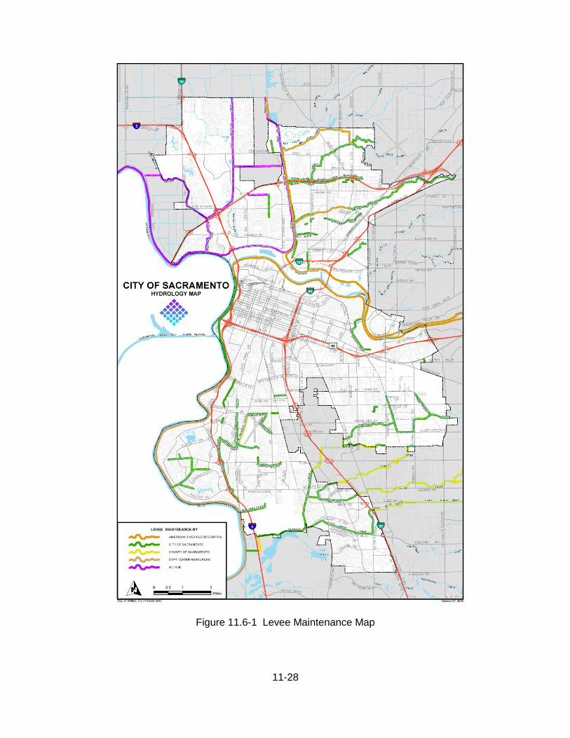
11.6 PIPELINES IN LEVEES 11.6.1 General The various levees within the City of Sacramento are maintained by the State Reclamation Board Department of Water Resources (DWR), Reclamation District 1000 (RD1000), by the American River Flood Control District (ARFCD), and by the City of Sacramento as shown in Figure 11.6-1. The U.S. Army Corps of Engineers (ACOE) also has jurisdiction over the levees on the Sacramento and American rivers and some of our major streams. Pipelines, conduits, utility lines, and appurtenant structures within a levee section must comply with all standards and regulations required by the maintaining agency and/or the ACOE. For levees maintained by DWR and RD1000, it is required to comply with California Code of Regulations (CCR) Title 23, Waters Division 1, Reclamation Board Section 123 (Reclamation Board Standards for encroachment through project levees) in addition to site specific requirements.(see Appendix E, except as modified below). An encroachment permit must be obtained from the appropriate agencies prior to construction in any levee section. The following are some of the general requirements for construction within a levee maintained by DWR or RD1000.
11.6.2 Flowline The flow line of any discharge pipe shall be installed above the 100-year frequency flood elevation within the levee crown. Any exceptions to this requirement shall be approved by the Director. 11.6.3 Discharge pipe Discharge pipe within the levee section shall be steel pipe or High Density Polyethylene Pipe (HDPE). The joints of the steel pipe shall be welded. Joints in the HDPE pipe shall be made by the thermal butt fusion process where the joints develop the full tensile capability of the pipe. 11.6.4 Welded steel pipe All welded steel discharge pipe within a levee section shall conform to the requirements of AWWA Standard C-200 and as modified herein. Pipe wall shall be a minimum of 0.25 to 0.50 inches thick and shall meet the requirements of ASTM A570 Grade 33 or equal. Pipe shall have a fusion bonded epoxy lining and coating per the requirements of AWWA C213. Welded steel pipe is required as casing under R/R track and in other high risk areas to minimize damage and for ease of maintenance. 11.6.5 HDPE pipe HDPE pipe within a levee section shall be DR 32.5 (51 psi), and shall conform to AWWA C906. 11.6.6 Minimum cover The minimum cover for the pipeline within a levee section shall be 24-inches at the crown of the levee and 19-inches on the levee slopes. This may require that the crown of the levee is raised. In such cases, the approach grades for the levee patrol road shall not exceed 10%.
11-28
Figure 11.6-1 Levee Maintenance Map

11-29
11.6.7 Vacuum release Adequate air and vacuum relief shall be installed at the crown of the discharge pipe. Air and vacuum relief valves shall be enclosed in a reinforced concrete vault located outside the levee patrol road travel way. A galvanized steel cover that is hinged, and can be locked, shall be installed on the vault. The top of the vault shall extend six (6) inches above the traveled way. The vault cover shall be vented. 11.6.8 Outfall structures The discharge pipe shall exit through a reinforced concrete outfall structure and shall be flap gated. The flap gate shall be mounted to the concrete outfall structure. 11.6.9 Erosion protection Erosion protection consisting of angular stone, reinforced shotcrete, or other types of revetment shall be placed on the adjacent and, if appropriate, the opposite canal bank. The erosion protection shall be extended at least ten feet upstream, downstream, above and below the outfall structure and shall have a suitable sized cut-off wall at all edges. Angular stone shall be Facing Class as specified in Section 72 of the State (CALTRANS) Standard Specifications or an approved equal. A suitable woven geotextile fabric shall be placed between the angular stone and the earth. The minimum thickness of angular stone shall be 12-inches. Typical erosion control details are presented in sketch RD-001, sheet 2 of 3. (Appendix E)

11-30
11.7 MANHOLES 11.7.1 Location Manholes shall be located at junction points, changes in gradient, and changes in conduit size and at, at a minimum, every 500 feet. 11.7.2 Manhole Types A Standard Manhole #3 shall be used for drain lines 24 inches or smaller in diameter and shall conform to Section 25 CSSS and to Section 38, drawing no. S-70 of CSSS. A Manhole #3A with an eccentric cone shall be used where the depth to flowline is greater than 8 feet and shall conform to Section 25 CSSS and to Section 38, drawing no. S-80 of CSSS. A Standard Manhole #4 shall be used for drain lines 27 through 42 inches in diameter, may be required at the intersection of three or more pipe, regardless of size and shall conform to Section 25 CSSS and drawing no. S-110 of CSSS. A Saddle Type Manhole shall be used on drain lines exceeding 42 inches in diameter, may be required at intersections of three or more pipes regardless of size and shall conform to Section 25 CSSS and drawing no. S-120 of CSSS. A reinforced concrete junction box may be required at the intersection of three or more larger pipelines or where a saddle manhole is not practical, at the discretion of the Director and shall apply to applicable portions of CSSS Section 10, 25 and 38, including Drawing S-310. Junction boxes shall be of pre-cast reinforced concrete which has been pre-approved by the Director or shall be cast-in-place reinforced concrete, designed by a professional structural or civil engineer registered in the State of California. Design, stamped calculations, drawings and submittals shall be approved by the Director prior to the start of construction. Junction boxes shall support H20 loading and impact loads and shall be accessible via one 36 inch manhole head and cover, at minimum. An appropriate manhole is required at the point of service of any private drainage system which connects to a public drainage system.

11-31
11.8 DROP INLETS AND GUTTER DRAINS 11.8.1 Types of Drop Inlets A Type “B” Drop Inlet shall be utilized for all street inlet installations except where another type inlet is specifically required and shall conform to Section 30 CSSS and Section 38, drawing no. S-10. A Modified Type “B” DI shall be used to mitigate odor problems as in the Combined Sewer System, or where otherwise approved by the Director and shall conform to Section 30 CSSS and to Section 38, drawing no. S-20 CSSS. A Type “B” DI Rolled Curb shall be used wherever there is a Curb & Gutter Type 1 and shall conform to Section 30 CSSS and to Section 38, drawing no. S-21 CSSS. A Ditch Box shall be used where there are roadside ditches, behind a sidewalk or where otherwise approved by the Director and shall conform to Section 30 CSSS and to Section 38, drawing no. S-30 CSSS. 11.8.2 Connections to Manholes Each drop inlet shall be connected directly to a manhole with a minimum 12-inch diameter pipe except at street intersections, two drop inlets may be interconnected with 12-inch diameter pipe prior to connecting to a manhole. In the combined sewer system drop inlet shall be connected directly to a manhole with a minimum 10-inch diameter pipe. 11.8.3 Tributary Flow and Placement Drop inlets shall be spaced so that flow does not exceed a run of 500 feet from any one direction or a total run of 1,000 feet from all tributary directions. Drop inlets shall be placed adjacent to handicapped ramps in high pedestrian traffic areas in such a manner that no more than 100’ of curb and gutter will drain through the ramp area. Drop inlets shall be placed 3’ from driveway sections, pedestrian ramps, round corners of pedestrian crosswalks, or the round corner side of pedestrian crosswalks. In new subdivisions, drop inlets shall be placed at lot lines and 3’ from the ends of curb returns at round corners.
11.8.4 Taps to Drop Inlet Taps to the back of drop inlets for private connections are discouraged and shall be allowed only if structures and improvements are situated above any street flooding in case the drop inlet becomes clogged. Also, the drop inlet lead to the main drain line must have adequate capacity for the flows from private property, plus flows from the street. Calculations must be provided to support the use of taps into the back of the drop inlet box and all such taps must be approved by the Director. Such private systems shall be maintained by the property owner.
11.8.5 Pass Over Drop Inlet Pass over drop inlets must be approved by the Director, and the distance between pass over

11-32
inlets shall not exceed 300 feet. For sizing drainage lines and inlets, the carry-over flow from upstream grates shall be the larger of either 50 percent of the previous grate accumulated flow or the amount determined from the Streets and Highways Manual published by the Institute of Transportation Studies. 11.8.6 Gutter Drains Gutter drains in general shall be used only in the Combined Sewer System (CSS) or in cases where the main pipeline is less than 12 inches in diameter. Installation shall be subject to the approval of the Director. Gutter drains type 20, 21, 22, 24 and Ditch Installation are to be designed and constructed in conformance with Section 30 CSSS and Section 38, drawing nos. S-42, S-45, S-50, S-55 and S-60 CSSS, respectively. Gutter Drains nos.21 and 22 are to be used exclusively in the combined sewer system, when a Modified Type B DI cannot be accommodated. Tributary flow and placement of the gutter drains shall be to the same requirements as drop inlets. Connections to manholes shall be 8" diameter SDR 35 PVC unless otherwise directed.

11-33
11.9 OVERLAND RELEASE 11.9.1 General Streets, other public rights-of-way or easements over private property shall be designed and graded in such a way as to provide overland release of runoff from storms greater than the capacity of the storm drain system. Any storm greater than a 100-year storm shall be safely routed through and/or around projects to an acceptable downstream drainage facility, while maintaining the required vertical clearance between the 100 year water surface elevation and building pads. For a 100 year storm, the depth of overland flow in feet, times the velocity in feet per second shall not exceed 6, except at schools, day-care facilities, orphaned children’s facilities or ungated playgrounds with adjacent residences, where the design depth times velocity shall not exceed 3. For 10 year storms, the depth of overland release shall not exceed .5 feet and the velocity of flow shall not exceed 4 feet per second. 11.9.2 Private Property Drainage easements/rights-of-way shall be provided to the City for areas where overland release will cross private property. These easements are to be shown on all recorded maps. Supporting documentation defining width, grade and cross-section shall also be provided to the City. The easement shall be kept free and clear of any obstructions that may restrict flow that may result in flooding. 11.9.3 Multi-Use, Erosion and Protection of Property
Multi-use of overland flow routes that are out of the street right of way is encouraged. Facilities may be constructed within easements on public or private property designated as overland release areas as long as they do not restrict the flow that may result in flooding. Any such multi-use facilities shall be designed such that an overflow event will not cause erosion or destruction of the multi- use facilities. Should any such destruction or erosion occur in overland release areas, the property owner shall take full responsibility for the maintenance and/or replacement of said facilities to an equal or better condition.

11-34
11.10 OPEN CHANNELS 11.10.1 General Requirements Open channels are not recommended for new designs in greenfield areas in the City but will be considered if: a. the stormwater runoff exceeds the capacity of a 72-inch diameter pipeline, or b. the surface water in the receiving body is at an elevation such that adequate cover
cannot be obtained over the outfall pipe (see section 11.5.3 to determine adequate cover).
The trapezoidal, concrete lined open channel of yesteryear is no longer an acceptable alternative for drainage conveyance in the City of Sacramento. Any variance from this policy shall be approved by City Council. Rather, open channel design shall provide an environmentally sensitive setting with natural landscaping, gently sloping sides, riffles, falls, sloughs, pools, a variety of possible water quality features and through which multi-use is encouraged: bike trails, walking or jogging trails, etc. A shallow, 8 foot wide, meandering low flow channel shall be incorporated into the design and shall be reinforced concrete lined for ease of maintenance and designed to support H-20 loading. Alternative surfaces may be proposed for the low flow channel if they prevent aquatic growth, are capable of supporting the necessary maintenance loads, and lends themselves to removal of silt and debris.
11.10.2 Channel Design Criteria Non-leveed channels shall, at a minimum, be designed to accommodate the 100-year, 10-day storm event with 1 foot of freeboard. Leveed channels shall, at a minimum, be designed to accommodate the 200-year, 10-day storm with 3 feet of freeboard.
11.10.3 Dimensional Limitations Channel bottoms shall vary in bottom width to provide a more natural appearance, with a minimum bottom width of 8 feet. Preferred side slopes shall be 4 horizontal to 1 vertical (4:1) or steeper and the maximum side slope allowed shall be 3:1unless otherwise approved by the Director. Side slopes shall vary in steepness to provide a more natural appearance. Channels with sides slopes steeper than 4:1 shall be provided with a 12 foot wide service road for every 7 feet of vertical channel depth. If the bottom of the channel is provided with an approved, minimum, 8 foot wide low flow channel, with channel side slopes steeper than 4:1, a 12 foot wide service road will only be required for every 13 feet of channel depth.

11-35
11.10.4 Velocity Limitation
Table 11.10-1
Soil Type Velocity (ft/sec)
Fine Sand (noncolloidal) 2.0
Coarse Sand (noncolloidal) 4.0
Sandy Loam (noncolloidal) 2.5
Silt Loam (noncolloidal) 3.0
Ordinary Firm Loam 3.5
Silty Clay 3.5
Fine Gravel 5.0
Stiff Clay (very colloidal) 5.0
Graded, Loam to Cobbles (noncolloidal) 5.0
Graded, Silt to Cobbles (colloidal) 5.5
Alluvial Silts (noncolloidal) 3.5
Alluvial Silts (colloidal) 5.0
Coarse Gravel (noncolloidal) 6.0
Cobbles and Shingles 5.5
Hard Shales and Hard Pans 6.0
Soft Shales 3.5
Soft Sandstone 8.0
Sound rock (igneous or hard metamorphic) 20.0
Channels shall have a sufficient average profile or longitudinal gradient to provide self-cleaning flow velocities (2.0 feet per second minimum average) under non-tailwater conditions, but not be so great as to create erosion. Maximum permissible velocities based on soil type are presented in Table 11.10-1. Increased allowable velocities may be obtained using available erosion control alternatives including natural soils with vegetative cover, and man-made materials (natural, synthetic of composite) with or without vegetative cover. Any such alternative design shall be supported by

11-36
research and field testing, to the satisfaction of the Director.
11.10.5 Channel Curvature Limitation For curved sections of channel, the center line radius shall be a minimum of 35 feet or at least twice the channel bottom width, whichever is greater.
11.10.6 Manning’s Roughness Coefficient The Manning’s coefficient of roughness to be used when designing a channel shall be as shown in Table 11.10 -2.
Table 11.10-2
Type of Channel
Design
Mannings “n”
Open channel with gunite lining (not acceptable for new channels)
0.018
Open channel not lined, with concrete low flow channel
0.030
Earthen channel
0.035
11.10.7 Channel Improvement Plan Requirements For all proposed channels, whether a realignment of an existing channel or a new channel, the following items shall be incorporated into the improvement plans at a minimum: a. Representative cross sections. b. Profiles of the existing channel flowline and top of bank profile for a minimum of 1000
feet upstream and downstream of the proposed project area in order to establish an average profile grade through the proposed development. The City has profile information for major drainage channels which may be obtained by contacting the Department of Utilities, Engineering Services Division at 916-808-1400 during business hours.
c. Plans drawn to current DOU drafting standards, at an appropriate scale showing all existing and proposed topography, all existing objects and features, all affected and adjacent property lines, easements and rights of way, and all existing utilities, plan views superimposed over recent aerial photos at the exact same scale.
d. All proposed improvements with their sections, details, dimensions, notes and delineations necessary for their proper construction.
11.10.8 Access For channels having side slopes steeper than 4:1, paved access roads, 12 feet wide with 3 foot

11-37
shoulders on each side, shall be provided parallel to and on both sides of channels including turn around areas as required. Pavement sections shall include an aggregate base course and an asphalt concrete surface and shall be designed using the Caltrans gravel equivalency method, based on the minimum R value of the underlying soil with H20 loading. Alternatives may be proposed which are functionally equivalent. The paved access shall be provided to the channel bottom at a minimum of two locations, to provide ingress and egress. Access roads shall not be required if the side slopes are 4:1 or less steep, if the channel is provided with a minimum 8 foot wide acceptable low flow channel and suitable access ramps from the street to the low flow channel. Bollards shall be provided and/or post and cable as shown in CSSS Drawing T-230, T-330 and T-340, as required, to prevent vehicular access to the maintenance roads and the channel. A pipe swing gate may also be used in lieu of removable bollards as approved by the Director. Access roads may also be used for pedestrian and bicycle access if approved by the Director.
11.10.9 Levees The design of channels that require levees shall comply with the Federal Emergency Management Agency (FEMA), U.S. Army Corps of Engineer (ACOE), and State Reclamation Board, and Department of Water Resources (DWR) requirements. The detailed design requirements for all channel with levees shall be determined on a case by case basis with consideration for existing soil profiles, groundwater, quality of fill material, etc. At a minimum, the leveed channel shall be designed to accommodate the 200-year, 10 day storm with a minimum of 3 feet of freeboard. After construction is completed, all levees shall be certified for flood protection by ACOE and by FEMA prior to acceptance by the City of Sacramento. The design of channels with levees shall reference a levee structure report, surveys, certified soils reports, as-built drawings of existing facilities, utility crossings and levee logs, and any other information required for FEMA compliance and all such items shall be submitted for approval with the channel design. Levee slopes shall be free from non-essential structures, encroachments or vegetative growth which may interfere with maintenance, inspection or hamper flood fighting activities. Levees in general, similar to channels, shall not be trapezoidal or geometric looking but shall, more or less, follow the center-line alignment of the integral channel with natural curves and shall be as irregular in cross section as the above requirements and space constraints will allow.
11.10.10 Fencing Only channels with side slopes steeper than 4:1 shall be fenced. Otherwise post and cable and bollards shall be provided as described above. Additionally, for areas of the City having an open space planning strategy, the maximum fencing requirement shall be post and cable unless otherwise approved by the Director. Channels with sides slopes steeper than 4:1 shall be provided with a six foot high chain link fence designed which shall be constructed in conformance with Section 31 of the CSSS on each side of the channel right-of-way. At all intersections between such channels and roads (bridge locations) fencing shall be provided to prevent public access and locked access gates

11-38
shall be provided for maintenance access from the roadway, recessed a minimum of 20 feet from the back of sidewalk or the edge of pavement, whichever is greater.
11.10.11 Utility Crossings When water, sewer or storm drain lines cross open channels, the encroachment and crossing designs shall comply with the manual of “Standards for Encroachments” developed by the State Reclamation Board, unless otherwise directed. The minimal crossing requirements shall be as follows: a. In all cases, the proposed future channel bottom elevation shall be used for design
purposes. Crossing details of pipe, piers, anchorage, transition couplings, etc. shall be shown upon a detail sheet of the plans in large scale.
b. For pipelines 12 inches and smaller, cast iron or ductile iron pipe shall be installed under
the full channel width plus 10 feet each side. For pipelines greater than 12 inches, the type of pipe installed shall be as approved by the Director. Special care shall be taken to provide a firm base for the pipe bedding. The plans shall specify that all soft or organic material within the channel bed shall be replaced with select imported backfill. In addition, a layer of 4" x 8" cobbles shall be placed and compacted on the top surface of the trench area for the full width of the bottom of the channel.
Unless otherwise directed, a clay cut-off wall shall be required at both sides of the channel. The clay cut-off wall shall be a minimum of 4 feet in length, shall extend the full width of the excavated trench, and shall extend 12 inches above and below the pipe.
c. Above grade crossings are not permitted. d. Other applicable information may be necessary.
11.10.12 Road Crossings Hydraulic design information including hydraulic grade line upstream and downstream of the crossing, proposed abutments, piers, soffit height, head walls, bottom treatment, culvert size and type (if applicable), grating to prevent unwanted access to culvert pipes, and erosion protection shall be submitted as part of the design for culverts and bridges.
11.10.13 Road Crossings RD1000 Bridge crossings of RD1000 facilities shall conform to the guidelines presented in Appendix E.

11-39
11.11 DETENTION BASINS
11.11.1 General The primary purposes of a detention basin are to mitigate flooding, to lessen the impact of peak flows on existing or proposed infrastructure (pump stations, channels and pipelines) and to improve water quality. The City of Sacramento has emphasized the value of detention basins in solving flooding problems in existing neighborhoods in infill areas because they may mitigate flooding where it is worst, they lessen the need to dig up and replace existing infrastructure, and by doing so they conserve limited drainage funds. Detention basins are effective in newly developing (greenfield) areas because they lessen the impact on receiving streams, they provide the best opportunity to obtain mandated water quality benefits, and they provide a variety of secondary use benefits. Detention basins allow for a number of beneficial secondary uses such as bicycle and walking/jogging paths, nature areas, endangered species habitat, bird sanctuaries, and a variety of recreational uses that may increase the value of surrounding homes and businesses and provide for a more desirable life style.
11.11.2 Design Guidelines Detention basins shall be designed in accordance with an approved master drainage plan and shall be one component in the system to maintain the required water surface elevations to prevent flooding. They may discharge to a receiving water body through a gravity outfall or by means of a pump station. The volume of available storage shall be in addition to any permanent pool, storage used to control groundwater intrusion, or volumes required to obtain water quality improvement as detailed in Section 11.12, herein. The design of detention basins shall provide for low maintenance and easy access. Detention basins shall be designed as an amenity to the neighborhood where they are located and may be integral to a park, habitat, open space, a landscape buffer, or lake (secondary uses). The design of secondary uses shall require coordination with one or more of the following City departments: Neighborhood Services, Planning, Development Services, Parks and Recreation and Utilities. Please refer to the Design guidelines for Joint Use Park/Detention Facilities herein in the Appendix. At this time, no portion of a detention basin subject to periodic flooding may be considered for Quimby Parkland credits.
11.11.3 Required Capacity Detention basins requiring pumping and those which rely on gravity outflow shall be designed large enough to safely contain the 100-year storm, assuming the worst case

11-40
storm duration (12-hour, 1 day, 36-hour, 5 day, or 10–day storm). This capacity shall be in addition to storage required for a permanent pool, storage used to control groundwater intrusion, or volumes required to obtain water quality improvement. An exception shall be made if overflow is planned, wherein no damage will occur due to overflow, a spillway is included, and the effects of overflow are in keeping with all other standards as detailed herein in Section 11. Any pump operation or gravity outfall associated with a detention basin shall provide for the holding time required for water quality purposes.
11.11.4 Maximum Allowed Discharge into Receiving Waters In all areas of the city, detention basin design must account for the peak water surface elevations of receiving waters, assure that their freeboard is not compromised under critical storm scenarios, and account for the capacity of receiving drainage systems so as to “do no harm”. Many of the receiving waters in the City of Sacramento are known to be at or beyond their design capacity during intense storms. Therefore detention basins shall primarily discharge when the surface elevation of the receiving water is low. For most receiving waters, the peak water surface elevation will lag behind the peak of critical storms. The same shall apply to detention basins which outfall into piped systems. Discharge rates into any of the canals maintained by RD1000 shall not exceed 0.1 cfs/acre of contributing drainage area, unless otherwise approved by RD1000. The maximum discharge, when pumped, shall be calculated at a minimum pumping head to ensure that the maximum pumped outflow does not exceed 0.1 cfs/acre.
11.11.5 Numbers of Pumps at Detention Basins For pumped detention basins, a minimum of four interchangeable pumps of equal capacity shall be provided, with each pump rated to pump 1/3 of the total pumping requirement. Maximum pumping capacity shall be based on three pumps operating and one pump in standby mode. Other configurations may be proposed for approval by the Director.
11.11.6 Low Flow Pumps for Detention Basins
For pumped detention basins, in addition to the primary pumps, a low flow pump shall be installed to convey low flows or dry weather flows, to accomplish water quality requirements, for energy efficiency, and for maintenance purposes. Low flow pumps may also be part of a pump-back system for water quality treatment or may assist in controlling ground water. Because of the cost of pumping groundwater due to stand-by electrical power usage, groundwater pumping will be limited as indicated in Section 11.11.10, herein.
11.11.7 Pump Operation at Detention Basins For pumped detention basins, the first pump shall be turned on consistent with water quality storage requirements. The off elevation shall not remove stored runoff at a faster rate than is allowed in Section 11.12, Water Quality, herein.

11-41
The second pump shall be turned on based on engineering judgment, a minimum of one foot above the elevation required for water quality storage. The off elevation shall not conflict with water quality requirements. The third pump shall be turned on at the maximum water surface elevation of the 10-year storm, with several duration storms evaluated to determine the most critical duration that will yield the maximum elevation. The off elevation shall be determined using correct engineering judgement. Of course, appropriate variations to the above will be allowed with the Director’s approval.
11.11.8 Pumping Power Sources Back-up generators shall be provided at each pump station as described herein in Section 12, Drainage Pump Stations.
11.11.9 Basin Slope Configuration Unless otherwise approved by the Director, the detention basin shall be designed with maximum side slopes of 4 feet horizontal to 1 foot vertical (4:1). Flatter slopes shall be required for areas intended for secondary use. For permanent pond areas, the configuration shall conform to the requirements of 11.12, Water Quality. If approved by the Director, 3:1 side slopes may be utilized only if a 12 foot wide maintenance bench is provided for every 7 feet of vertical depth. The bench and slopes shall be graded and armored as required to prevent erosion and the bench shall have an all weather surface.
11.11.10 Groundwater in Detention Basins Certain areas of the City including, but not limited to, Natomas and the Pocket Area are subject to high groundwater elevations which are dependent on the river stages, canal elevations, seasonal rainfall, irrigation activities, releases from upstream reservoirs, etc. The groundwater elevations can have large annual variations and be near the surface during wet winters when the river stage remains high. Test borings frequently exhibit artesian conditions. Dewatering during construction and the control of groundwater inflow during operation are key components of the detention pond design. The volume of groundwater allowed to enter a detention basin or its contiguous pump station shall be limited so as to control the increased cost of pumping and to retain the storage volume required to mitigate flooding. The detention pond shall be designed based on the following criteria. An analysis of groundwater shall be provided per the requirements of Section 11.2, herein. The maximum allowable groundwater inflow volume shall be: 1.8 acre-feet per year per acre of tributary area.

11-42
The maximum allowable groundwater inflow rates shall be: 0.015 cfs per tributary acre during wet winter conditions and 0.0009 cfs per tributary acre during dry weather and low river stage. It may be necessary to further reduce allowable inflow, based on flood storage requirements.
A geotechnical evaluation and report shall be provided in accordance with Section 11.2, herein. The geotechnical report shall make recommendations for mitigating groundwater inflow which exceeds the above criteria and necessary measures shall be included in the construction documents. During construction, the geotechnical engineer shall determine the actual volume and inflow rate in the field and adjustments shall be made to the groundwater control measures to accommodate any changes, by change order.
11.11.11 Clay Liner An impermeable clay liner may be used to control groundwater infiltration. It may consist of a “thick clay liner” of suitable native material that meets the requirements of impermeability or imported bentonite or it may be a less thick manufactured product, if approved by the Director. The clay liner shall be designed so as to maintain basin volume, flow rate, and limit groundwater intrusion as described herein and also to resist buoyancy. The clay liner may incorporate an under-drain system. The design shall incorporate the recommendations of the geotechnical report. Additional requirements shall include the following:
Thick Clay Liner: Thick clay liners shall be a minimum of 1 foot thick, or thicker. Under-Drain System: An under-drain or french drain system may be used in conjunction with a clay liner to reduce the thickness required of the clay liner and/or to mitigate buoyancy forces. If selected, the under-drain system shall adhere to the following: 1. Drain rock shall consist of durable, crushed stone having 100 percent passing the 1-
inch sieve and less than 5 percent passing the No. 4 sieve. If a mineral filter/drain rock is proposed, it shall be compatible with formation material.
2. Synthetic filter fabric shall be a woven fabric with an equivalent opening size (EOS),
US Standard Sieve, of between 40 and 70, a permeability of at least 0.02 centimeters per second, a minimum flow rate of 50 gallons per minute per square foot of fabric, and a minimum puncture strength of 50 pounds.
Synthetic filter fabric shall be placed in accordance with manufacturer’s recommendations. Surfaces to receive filter fabric shall be free of loose or extraneous material and sharp objects that might damage the filter fabric during installation.
3. Trench depth and spacing shall be as recommended in the geotechnical report and
may be adjusted in the field depending on the subsurface conditions as directed by the project geotechnical engineer, who shall observe field conditions and confirm required depths and spacing during trench excavation.

11-43
4. Perforated drain pipe shall consist of schedule 40 PVC, 8 inches in diameter, with ¼-
inch diameter (maximum) perforations, 12 to 24 inches on-center, placed down. Pipe invert shall be no more than 4 inches above trench bottom. Pipe drainage shall be collected in a solid conduit and directed to a sump or other suitable location for disposal. Perforated and collector pipes shall be designed to drain and supporting calculations shall be provided.
11.11.12 Dewatering for Secondary Uses of Detention Basins Many possible secondary uses for detention basins require a well drained surface condition. A well drained surface also helps to maintain vector control. The design of detention basins shall ensure surface drainage in accordance with their proposed secondary uses and to ensure vector control. Playing surfaces shall slope at a minimum of 1%. Underdrain systems shall be provided such that no ponding of water occurs and so that there are no soggy play areas. Appropriately designed french drains may help accomplish this. Detention basin pump stations or gravity outfall structures shall be designed to facilitate proper dewatering.
11.11.13 Outfall/Inlet Structures All pipes conveying flow into or out of the basin shall be provided with a reinforced concrete outfall or inlet structure, in accordance with Sections 10, 20, 21, and Section 38, dwg. nos. 270, 280, 290, and 300 CSSS. These structures shall be equipped with trash racks, flap gates, and/or sluice gates as required. No wooden stop logs will be allowed. Access into pipes by the public shall be prevented. Alternative designs or variations for these structures may be used if approved by the Director for which plans shall be submitted together with structural calculations signed and stamped by a professional engineer, currently registered in the State of California. Suitable slope and erosion protection shall be provided around these structures. At a minimum, No.2 Backing as specified by Caltrans shall be required with synthetic woven filter fabric and cutoff walls on all sides. An all weather vehicle access road shall be provided to the top of each such structure a minimum of 12 feet wide and at an elevation above the 100 year water surface elevation.
11.11.14 Concrete Low Flow Channel

11-44
If the basin is to be subject to any year round, summer or nuisance flow, a shallow, trapezoidal shaped, meandering low flow channel shall be incorporated into the design and shall be steel reinforced, concrete lined for ease of maintenance. It shall be designed to accommodate maximum nuisance flows and dry weather flows and shall be sloped to drain. Its alignment shall be designed to complement the natural habitat or other secondary-use of the detention basin. It may incorporate tinted concrete, stones or other elements along its banks to help give it a more natural appearance. It shall be a minimum of 8 feet wide and 12 inches deep with 2:1 side slopes and shall consist of a 6" thick reinforced concrete section reinforced with a minimum of 6x6 6/6 WWM and shall be able to support H20 loading. Alternatives to reinforced concrete may be used for low flow channels if they support the required loads and if they are approved by the Director.
11.11.15 Water quality of Permanent Pools Basins which incorporate a permanent pool shall maintain acceptable water quality: water relatively free from algae blooms, any offensive odor, or other noticeable adverse condition. To maintain acceptable water quality in detention basins incorporating a permanent pool, the depth of water shall be a minimum of 4 feet, except for the sloped area at the shoreline. If the source of fresh water entering the basin from runoff is not sufficient to maintain acceptable water quality in the basin, a well or alternative fresh water source shall be provided and/or water aeration measures employed such as fountains or waterfalls. Recirculating pumps may be provided at detention basin pump stations for this purpose.
11.11.16 Fencing Consistent with the multi-use concept, fencing will be minimal and limited to post and cable. Bollards and post and cable fencing will be constructed as required to prohibit vehicular access. A three-foot chain link fence may be required in certain areas to restrict human access and keep domestic animals out of nature areas. When back-on lots are adjacent to the detention basin, a minimum 8 foot high engineered, decorative, reinforced masonry wall shall be placed on the property line separating the back-on lots from the detention basin, with the design approved by the Director.
11.11.17 Landscaping and Irrigation Because of the secondary-use concept, landscaping and irrigation may be required as part of the detention basin. All planting and irrigation shall be according to the CSSS. All irrigation supply systems which includes pipes larger than 4" in diameter shall be designed and constructed in accordance with CSSS Section 27. Coordination with the following departments will be necessary to identify the appropriate secondary uses of the basin and to assure conformance with standards and needs: Department of Utilities, Department of Parks and Recreation, and the Planning Division.

11-45
Landscaping shall be in addition to the planting associated with the water quality requirements and may include trees, shrubs, groundcover, wild flowers, turf grasses, irrigation, walking/jogging paths, bicycle trails, native habitat and other elements. Maintenance access roads may double as walking/jogging paths or bicycle paths. However, such paths shall not dead-end but shall allow pedestrian travel around the facility and/or through it to other destinations.
11.11.18 Maintenance Vehicle Access: Vehicular access is necessary for the proper maintenance of the detention basin. An access road shall be provided to the top of all pipe inlets and outlets and, if side slopes exceed 1:4, an access ramp or ramps shall be provided to the basin bottom. All access roads and ramps shall be a minimum of 12 feet wide, shall have an all-weather surface, with a minimum turning radius of 40 feet, and a maximum slope of 10%. Access along the basin bottom shall be via the 8 foot wide concrete bottom of the low flow channel with appropriate access points. Access for Harvesting: Control of annual weeds, cattails and thules will require periodic harvesting in the water quality areas and along the banks of permanent ponds. Vehicular access shall be provided for these functions as specified in Vehicle Access herein, adjacent to the permanent pool or other feature and a suitable flat area provided from which to work. Maintenance Plan: A maintenance plan shall be submitted and approved by the Director prior to approving the design of the facilities. The maintenance plan shall include, but shall not be limited to, the following: 1. A map showing: a. areas to be mowed b. areas not to be mowed c. areas where herbicides may be used d. tree plantings and watering schedules e. drainage inlet facilities including stilling ponds f. the 10/50/100 year water surface elevations for both the detention pond and any
influent channels 2. A description of how the areas that are not to be mowed are to be maintained:
weed and algae control practices. 3. A description and annual schedule for maintaining environmental sensitive areas. 4. A pump operation schedule and an explanation of how such supports the water quality
features of the detention pond. 5. A list of appropriate herbicides to be used to control weeds, ect. 6. An itemized list of any facilities/equipment that require a specific maintenance
procedures including, but not limited to, the following: a. sedimentation basins b. recreational equipment c. trail access road maintenance d. pond recirculation aeration facilities

11-46
7. List of maintenance equipment requirements 8. Master calendar for seasonal/periodic activities and inspections Funding Detention Basin Maintenance: The DOU will provide “Utility Level Maintenance” of detention basins. This will include mowing twice annually, removing surface debris following major storms, unlimbering inlet outlet structures of debris, and assuring that conveyance pipes and low flow channels are functioning. DOU will maintain access roads. DOU will also fully maintain all pump stations associated with detention basins. The cost of maintaining any other detention basin features such as sports fields, water quality features, irrigation, landscaping, and facilities associated with other secondary uses is beyond the expertise and budget of the DOU. It will be necessary for developers to provide funds for maintenance of these in the form of a Maintenance District or other acceptable financial instrument that is approved by the Director.

11-47
11.12 WATER QUALITY Development projects or other projects constructed for the City of Sacramento shall contain water quality measures whose design, construction and maintenance shall be in accordance with the “Stormwater Quality Design Manual for the Sacramento and South Placer Regions” (manual) as found on the internet at http://www.sacramentostormwater.org . The manual is periodically updated and the current version of the manual shall apply. The measures identified in the manual are for the purpose of reducing urban runoff pollution to the maximum extent practicable (MEP) and shall be designed and constructed under the supervision of a California licensed professional engineer and other specialists as required. Table 3-2 of the manual indicates the projects which are subject to the requirements of the manual and which measures are to be applied. All developer financed water quality basins which are constructed for the City of Sacramento shall include provisions for financing all on-going maintenance in perpetuity and in a manner that is acceptable to the Director.