design and implementation of on-line monitoring system of
TRANSCRIPT

Design and Implementation of On-Line Monitoring System of Substation equipment
Xiao-ying LI 1,a,Dan ZHANG 2,b
1College of Computer Science and Technology, Wuhan University of Technology, Wuhan Hubei 430000,China
2College of Software Engineering, Zhejiang University, Ningbo Zhejiang 315000, China [email protected],[email protected]
Keywords: Substation, Equipment Sates, Online Monitoring, IEC61850
Abstract: This paper introduces the on-line monitoring system of substation equipment combining non-standard access protocols and IEC61850 protocols, which change the on-line monitoring system mode provided by traditional sensor manufacturers into unified communication. What’s more, it develops front access equipment supported by IEC61850 protocols as well as non-standard access protocols. Besides, the master system fully supports IEC61850 protocols. It realizes remote control and sensor on-line monitoring technology, which supports data concurrent process, greatly increases compliance and meanwhile decrease operation and maintenance cost. The function and property can meet the requirement of project based on practical running tests.
1 Introduction The expanding of electricity grid leads to the increasing of substations. In order to ensure
equipment running well, varieties of sensors are used. So it’s hard to schedule equipment maintenance period and collect offline data. At the same time, substation’s equipment has the functions of telemeter, tele-signaling, tele-control and tele-regulation in power. Every monitoring center is staffed with power production management system (PMS), which can collect related data and analyze it for the production management. However, different signals use different protocols and equipment management systems are relatively independent. It’s hard to unify and standardize different types of datas, causing great difficulties to maintain and manage. It’s high time that we should have an efficient online substation equipment monitoring system to achieve real-time monitoring.
This system uses Condition information Acquisition Controller (CAC) preposition system which provides open interfaces to support standard statute and private interface to support non-standard statute. Base on the standard IEC16850, monitoring substation background, communication managing and protecting information substation can attach to IEC61850 equipment directly.
2 The design of framework of on-Line monitoring system of substation equipment Taking account of the actual application of the State Grid scheme and system‘s target and
designed principles, the system framework is showed in picture 1: This system is divided into four layers: The first layer is smart sensor layer, which has many
complex types of devices and supports very different protocols; The second is access layer. In this layer, data collected from first layer will input system in different ways based on different conditions. The third is data processing, analyzing, storing service layer. Intergraded and processed data input substation equipment monitoring system and real-time data also can be written in PI system for massive real-time data storage. Considering universality, the design deserved real-time data center apart from PI, to provide the same data storage ability for the application without PI system; The fourth is application and interface layer. The system provides data exchange interface for production management system and data center of State Grid.
International Conference on Automation, Mechanical Control and Computational Engineering (AMCCE 2015)
© 2015. The authors - Published by Atlantis Press 560

In old system, condition monitoring equipment is at a low level of standardization, causing diversity of pre-system. In the design,CAC is used to make a standardized control of types of monitoring devices. Upgrade the old private preposition system to the common preposition system, to improve the resource utilization and cut cost.
picture 1 framework of system
3 Design and implementation of CACpreposition system The CAC pre-system is divided into four function modules: Downlink data
communicationmodule, data processmodule, uplink data communication module and auxiliary function module. Downlink standard instructions send standard instructions to Condition Monitoring Agent (CMA) through access module, analysis module and distributing module. As picture 2Shows:
picture 2architecture of pre-system
3.1 Downlink data communication module The class diagram of downlink data communication module is showed in picture 3.Adater,
superclass of all adapter‘s interfaces, implementsRunableinterface. TcpAdapter and TcpConnect are data receiving interfaces provided for lower sensors by this module.
Class BiLeiQiAdapter deals with data collected by the lighting arrester; Class DJXAdapter deals with data collected by battery; Class UniversalAdapte deals with data collected by oil chromatographic; And class IEDDataFileAdapter deals with data collected by sensors who support the IEC61850 protocol.
561

picture 3downlink data module inheritance
3.2 Data process module Data process module not only receive the data from downlink data module and analyzes it
according to communication protocols, but also uses matching model to encapsulate data. 3.3 Uplink data communication module As picture 4 shows, real-time thread DataDeliver1 detects the buffer queue continually,
afterrunning. Whenbuffer queue has data, Datadeliver1 will get it and delete it in queue, then making a connection with main station background service-DataServer to send the package. If exception occurs, the package is added to history database.
picture 4uplink data module transmission timing picture
The history data thread-DataDeliver2 detects MySQL database continually, afterrunning. When database has data, DataDeliver2 gets copy of package, then making a connection with background service DataServer to send package. IfDataDeliver2 gets successful return, package will be stricken from database. If exception occurs or DataServe returns the signal thatpackage is not handledproperly, this copy will be discarded.DataDeliver2 still detect the database.
3.4 Auxiliary function module Auxiliary function module includes the functions of computersswitch, heartbeatmonitoring, and
log backup, timing, and remote maintenance and so on.
4 Realization of communication protocols 4.1 NonIEC61850standard protocols According to their products, many factories have developed transport protocols widely used in
substations. The system has provided open interface to support those protocols. Lighting arrester protocol, battery protocol and oil chromatographic [1]protocol have been accessed successfully.
Take the oil chromatographic protocol for example. The old transformer monitoring and diagnostic methods are still restricted to electrical test, which is difficult to find some local faults and local overheat problems. But, by analyzing changes of gas chromatographic data to find faults in transforms is more accurate.
4.2 IEC61850 standard protocol IEC61850[2] is an international standard, proposed by IEC TC57, for the seamless
communication architecture in substation automation system (SAS).IEC61850 specifications represent the developing direction of the SAS communication architecture. Due to using the technology of object-oriented modeling, adopting abstract communication service interface[3](ACSI) and supporting TCP/IP protocol, the management and extending of functions in SAS will be more flexible and convenient. The most important thing is that the major aim of IEC61850, operations in devices with different protocols, are realized.
The system has used IEC61850 in preposition CAC.There are many sensors being accessed by
562

this way, for example the partial discharge monitoring, the core grounding current system, cooler fan monitoring,SF6 gas density and moisture monitoring, the circuit breaker dynamic characteristic monitoring and current transformer insulation monitoring,
IEC61850 is based on client/service model[4] to work. Client initiates a request then server response to it, giving the feedback [5]after analyzing request. Client includes two parts: One is main program based on client-client_Id developed by MMS-EASE Lite, another is configurationfile, including types of osicfg.xml,*.icd,*.cfg and so on. Different files play different roles, for example file *.icd, provide for sensors, is used to give measuring point in the hierarchy of entire sensor.
<LN desc="SF6 gas installation 1" ext:uri="" inst="1" lnType="SF6_SIMG" lnClass="SIMG"> <DOI name="Tmp"> <DAI name="dU">
<Val>SF6 temperature of gas installation 1 /Val> </DAI> </DOI> </LN>
5 Realization of I2 communication protocols I2 interface has been used to data exchange between provincial companies and substation‘s main
station systems. The example of data upload: CAC initiates a quest to send data from condition monitoring system under its jurisdiction. CAC calls the CAG‘s data uploading function to send data from condition monitoring system in every data uploading cycle.CAG returns the result received by monitoring data. As picture 5 shows:
picture 5upload data
Public String uploadCACData (String strXMLParams) function is used to data transition process.CAC calls this function to send monitoring data. There are many types of control instructions and information in result returned by CAG.Input and output parameters are well formed XML. (Attention: the maximum XML’s length can’t exceed 4 M.If the data is excessive, please upload it several times)
6 Design and implementation of on-line monitoring system of substation equipment The on-line substation equipment condition monitoring system can be divided into two parts:
One part is data receiving, processing andstoring services in background, another is Web display part. The system’s more functions are showed in picture 6:
picture 6functions of on-line substation equipment condition monitoring system
6.1 Service ofreal-time data accessing Start-up process of background real-time data accessing service[6] is showed in picture 7.when
563
DataServer starts working, it will call Threadpool to build a connection pool. When DataServer monitors connection, it will check connection pool and get the free connection, to deal with the package by independent way. This method can improve system’s concurrent processing ability. Service of processing data uploading
6.2 Service of real-time data processing Picture 8 is the timing diagram of master station’s data-processing.DBThread.After receiving
data,DBThread will call AcqpointService.Then AcqpointService calls ParseDataService to analyze data and save the result to DataNode.Then object of DataNode will be send to AcqpointDao who is responsible for storing and sending data to PI server.
picture 7 main station background servicepicture 8 of main station data process
6.3 Service of real-time data output The object of AcqpointDao not only stores data, but also calls WebService to write into power
production management system (PMS). DataMessageProcessor service’s function, PostXml, is used to define formats of output and input. There are two types of messages in PostXml fuction.One is input message who correspond to DMPPostXmlMessage in Xml’selements, another is output message who correspond to DMPPostXmlMessage
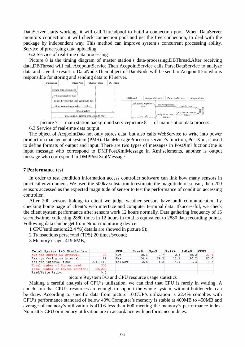
7 Performance test In order to test condition information access controller software can link how many sensors in
practical environment. We used the 500kv substation to estimate the magnitude of sensor, then 200 sensors accessed as the expected magnitude of sensor to test the performance of condition accessing controller.
After 200 sensors linking to client we judge weather sensors have built communication by checking home page of client‘s web interface and computer terminal data. Ifsuccessful, we check the client system performance after sensors work 12 hours normally. Data gathering frequency of 15 seconds/time, collecting 2880 times in 12 hours in total is equivalent to 2880 data recording points. Following data can be get from Nmon monitoring device:
1 CPU’sutilization:22.4 %( details are showed in picture 9); 2 Transactions persecond (TPS):20 times/second; 3 Memory usage: 419.6MB;
picture 9 system I/O and CPU resource usage statistics
Making a careful analysis of CPU‘s utilization, we can find that CPU is rarely in waiting. A conclusion that CPU’s resources are enough to support the whole system, without bottlenecks can be draw. According to specific data from picture 10,CUP’s utilization is 22.4% complies with CPU’s performance standard of below 40%.Computer’s memory is stable at 400MB to 450MB and average of memory’s utilization is 419.6 less than 600 meeting the memory’s performance index. No matter CPU or memory utilization are in accordance with performance indices.
564

8 Conclusion With the development of smart grid, the union of e Substation Equipment Condition Monitoring
System has become the inevitable trend [7]. Substation Equipment Condition Monitoring System is an important technique to achieve overhaul and manage of Substation Equipment Condition and improve specializing in the production of lean substation operation management level. Through sensors, network of communication and information process technology to realize functions of real-time perception, supervision and warming, analysis and diagnosis, estimation and prediction of equipment’s condition. The System has been applied in practical projects and performed successfully. Following work will focus on analyzing data from equipment to provide reliable basis for making a decision of equipment condition.
References [1]Yangchow Ding, Qian Guo and Ping Song. Oil chromatographic analysis of transformer[S]. China Electric Power Education,2010. [2]Yanming Ren, Lijun Qin and Qixun Yang, Introduction and Analysis of IEC61850 Communication Protocol System [J]. Automation of Electric Power Systems,2000,24(8):62-64. [3]Wei He, Wengui Liao and Songyi Zhu.Contradiction in the Mapping of IEC61850 and MMS and Its Solutions [J]. Automation of Electric Power Systems,2006,30(23):97-100. [4]Yun Shen, ZhenhongZhao. Research and Implementation on MMS for Heterogeneous Environment [J].Journal of Tsinghua University (Sci&Tech),1998,38(10):93-96. [5]Zaijun Wu, MinqiangHu. Research on a Substation Automation System Based on IEC61850 [J].Power System Technology,2003,27(10):61-65. [6]Yongliang Li Zhixiong Yuan, BinChen and so on. Analysis and Implementation of TCP/IP Based Specific Communication Service Mapping MMS in IEC61850 [J].Power System Technology, 2004,28(24):33-38. [7]Kai Yang. Future Development of Substation Automation System [J].Telecommunication for Electric Power System,2007(12).
565