design and implementation of indoor environment monitoring
TRANSCRIPT
National Conference on Emerging trends in Information, management and Engineering sciences “NC’ea-TIMES#1.0”-2018
ISSN: 2395-1303 http://www.ijetjournal.org Page 1
Design and Implementation of Indoor Environment Monitoring and Control System
Mr.K.Naganarasaiah Goud1, Mallem.Nagamani 2
1Assistant Professor, Department of ECE, AITS, Rajampet, Andhra Pradesh, India 2PG Scholar, Department of ECE, AITS, Rajampet, Andhra Pradesh, India
Email: [email protected], [email protected]
I. INTRODUCTION
Temperature, pressure, humidity and the quantity of gasses measured with environmental monitoring system (EMS).Those are all called parameters of environment. These parameters used by many applications as in Industries, smart
homes and weather forecasting [2].Now a day’s IOT (Internet of Things) playing a major role in all applications. In all over the world the emerging new technology is IOT. It became an important part of new generation of IT (Information
Technology) and rapidly strengthens its growth and used in many applications such as home automation systems, monitoring and controlling systems [1].Experts saying that 30 billion objects will emerged with IOT technology in 2020 and
will earn up to 7. Trillion by 2020. In previous years the constant development of colleges, Industries and universities and the increasing number of graduate’s practical abilities, the education management had
gone through several changes to recruit teaching staff and the construction of labs where number o servers and computers will be used. The main challenge is about to manage the
environmental space occupied by those computers and servers.
The issue is about to look over the complexity and mobility of each user. At present the education management will manage this issue by providing extra staff as backward process to monitor and controller environmental issues like air condition, temperature and the consuming time of users. It is a waste of time to hire backward staff and a failure to use manpower to monitor the environment [1].In addition to the interface design this work presents a solution to establish a rare room to
monitor and control indoor environment. In adapted technologies they were focused on the elder comfortness as they were control home automation through television set by using remote control and few icons without
taking the help of navigation keys. After examines all the recent technologies here we are adapting few more sensors, controller and motors to measure the correct analysis of environment. The Raspberry Pi is going to collect the data from the various sensors and process it in cloud. Here cloud is used as a storage purpose to store the data through that the person will manage the indoor environment far away from his or her living place. Through GPIO pins of Raspberry Pi we process the data to the motors and by using
RESEARCH ARTICLE OPEN ACCESS
Abstract: IOT is a growing technology at present in whole world. It is estimated to be 20 million of devices are going
to adapt IOT technology in 2020. So that we are adapting IOT technology in indoor environment system. At present
in this busy life schedule it became tuff job to control and monitor environment system. In the previous projects
EMAC system had monitored and controlled in only local area .Here we are using 4 types of sensors as GAS,
Temperature, IR and LDR sensors to provide different outputs. We are going to control and monitor the indoor
environment through manual mode of operation as well as auto mode of operation. It is a great impact in the design
of control and monitors the indoor environment system. It reduces the manpower. If any accidents going to be occur
it will be rectify by using this system. It is good solution for the large rooms equipped with several servers and
computers like as colleges, software companies and universities.
Keywords— IOT, Raspberry Pi, sensors.
National Conference on Emerging trends in Information, management and Engineering sciences “NC’e
ISSN: 2395-1303
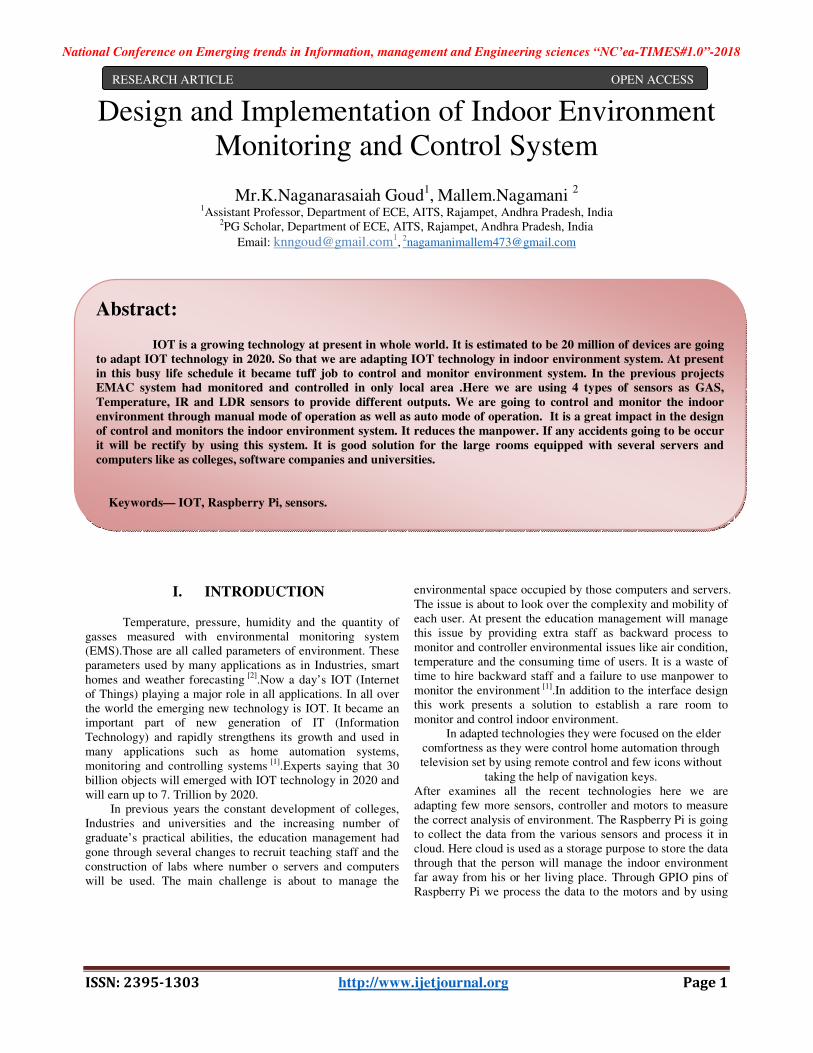
HDMI cable and then at a time we are going to monitor and
control the indoor environment.
We are using Raspberry Pi 3 board to utilize the Wiadapter. The main intension is to reduce the manpower so that
purpose we are using here wireless technology to monitor the whole environment and also give alert to them if any accidents going to happen.
Figure 2: Circuit diagram with connections
II. DESIGN AND IMPLEMENTATION
Conference on Emerging trends in Information, management and Engineering sciences “NC’e
1303 http://www.ijetjournal.org
time we are going to monitor and
We are using Raspberry Pi 3 board to utilize the Wi-Fi adapter. The main intension is to reduce the manpower so that
purpose we are using here wireless technology to monitor the ronment and also give alert to them if any accidents
Figure 2: Circuit diagram with connections
DESIGN AND IMPLEMENTATION
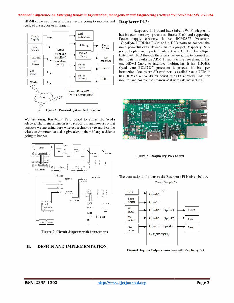
Raspberry Pi-3:
Raspberry Pi-3 board have inbuilt Wihas its own memory, processor, Emmc Flash and supporting Power supply circuitry. It has BCM2837 Processor, 1GigaByte LPDDR2 RAM and 4-USB ports to connect the
more powerful extra devices. In this projectgoing to play an important role act as a CPU .It has 40Extended GPIO through these pins we are going to connect all the inputs. It works on ARM 11 architecture model and it has
one HDMI Cable to interface multimedia. It has 1.2GHZ Quad core BCM2837 processor it process 64 bits per instruction. One micro SD card port is available as a ROM.It has BCM43143 Wi-Fi on board 802.11n wireless LAN for monitor and control the environment with internet o things.
Figure 3: Raspberry Pi-3 board
The connections of inputs to the Raspberry Pi is given below,
Conference on Emerging trends in Information, management and Engineering sciences “NC’ea-TIMES#1.0”-2018
Page 2
3 board have inbuilt Wi-Fi adapter. It has its own memory, processor, Emmc Flash and supporting Power supply circuitry. It has BCM2837 Processor,
USB ports to connect the
more powerful extra devices. In this project Raspberry Pi is going to play an important role act as a CPU .It has 40-pin Extended GPIO through these pins we are going to connect all the inputs. It works on ARM 11 architecture model and it has
one HDMI Cable to interface multimedia. It has 1.2GHZ d core BCM2837 processor it process 64 bits per
instruction. One micro SD card port is available as a ROM.It Fi on board 802.11n wireless LAN for
monitor and control the environment with internet o things.
3 board
The connections of inputs to the Raspberry Pi is given below,
National Conference on Emerging trends in Information, management and Engineering sciences “NC’ea-TIMES#1.0”-2018
ISSN: 2395-1303 http://www.ijetjournal.org Page 3
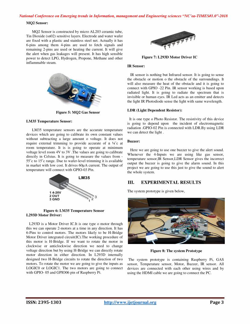
MQ2 Sensor:
MQ2 Sensor is constructed by micro AL203 ceramic tube, Tin Dioxide (sn02) sensitive layers. Electrode and water wafer
are fixed with a plastic and stainless steel net. Actually it has 6-pins among them 4-pins are used to fetch signals and remaining 2-pins are used or heating the current. It will give the alert when gas leakages will present. It has high sensible power to detect LPG, Hydrogen, Propone, Methane and other inflammable steam.
Figure 5: MQ2 Gas Sensor
LM35 Temperature Sensor: LM35 temperature sensors are the accurate temperature
devices which are going to calibrate its own constant values without subtracting a large amount o voltage. It does not require external trimming to provide accurate of ± ¼˚c at room temperature. It is is going to operate at minimum
voltage level room 4V to 3V .The values are going to calibrate directly in Celsius. It is going to measure the values from -55˚c to 15˚c range. Due to wafer-level trimming it is available in market with low cost. It drives 60µA current. The output of
temperature will connect with GPIO-03 Pin.
Figure 6: LM35 Temperature Sensor
L293D Motor Driver:
L293D is a Motor Driver IC.It is one type o motor through
this we can operate 2-motors at a time in any direction. It has 6-Pins to control motors. The motors likely to be H-Bridge Motor Driver integrated circuit(IC).The working procedure of this motor is H-Bridge. If we want to rotate the motor in
clockwise or anticlockwise direction we need to change voltage direction but by using H-Bridge we can directly rotate motor direction in either direction. In L293D internally designed two H-Bridge circuits to rotate the direction of two
motors. To rotate the motor we are going to give the inputs as LOGIC0 or LOGIC1. The two motors are going to connect with GPIO- 05 and GPIO06 pin of Raspberry Pi.
Figure 7: L293D Motor Driver IC
IR Sensor:
IR sensor is nothing but Infrared sensor. It is going to sense the obstacle or motion o the obstacle of the surroundings. It will also measure the heat of the obstacle and it is going to connect with GPIO -22 Pin. IR sensor working is based upon radiated light. It is going to radiate the spectrum that is invisible or human eyes. IR Led acts as an emitter and detects
the light IR Photodiode sense the light with same wavelength.
LDR (Light Dependent Resistor):
It is one type o Photo Resistor. The resistivity of this device is going to depend upon the incident of electromagnetic radiation .GPIO-02 Pin is connected with LDR.By using LDR we can detect the light .
Buzzer: Here we are going to use one buzzer to give the alert sound.
Whenever the 4-Inputs we are using like gas sensor, temperature sensor,IR Sensor,LDR Sensor gives the incorrect output the buzzer is going to give the alarm sound. In this project we are going to use this just to give the sound to alert
the whole system.
III. EXPERIMENTAL RESULTS
The system prototype is given below,
Figure 8: The system Prototype
The system prototype is containing Raspberry Pi, GAS sensor, Temperature sensor, Motor, Buzzer, IR sensor. All devices are connected with each other using wires and by
using the HDMI cable we are going to connect the PC.
National Conference on Emerging trends in Information, management and Engineering sciences “NC’ea-TIMES#1.0”-2018
ISSN: 2395-1303 http://www.ijetjournal.org Page 4
Initially raspberry pi takes the 5V supply it is going to distribute the power to all sensors and motors .At initial condition through ROM (Micro SD card) booting process will be done after that all pins are enabled. That is shown in the
below figure,
Figure 9: When the initial process going on (booting) All pins are going to be enabled then by using the monitor we can control or monitor indoor environment the results are described in below figures. Here we are observing
3 outputs as, if the LDR detects the light will be ON, If the temperature sensor detects the FAN will be ON, If the GAS sensor detects gas waves the Buzzer will be ON. This will be monitor through auto mode. If we want to control the system
it must be in manual mode.
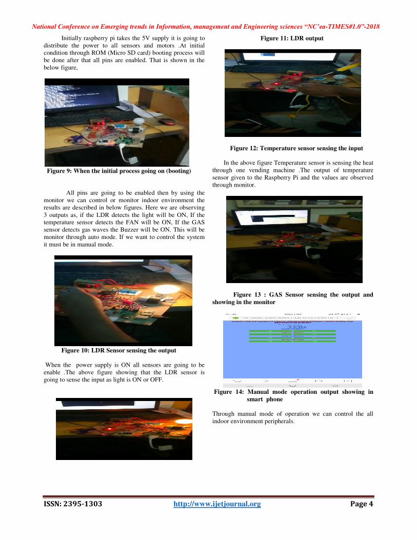
Figure 10: LDR Sensor sensing the output When the power supply is ON all sensors are going to be enable .The above figure showing that the LDR sensor is going to sense the input as light is ON or OFF.
Figure 11: LDR output
Figure 12: Temperature sensor sensing the input In the above figure Temperature sensor is sensing the heat through one vending machine .The output of temperature sensor given to the Raspberry Pi and the values are observed through monitor.
Figure 13 : GAS Sensor sensing the output and
showing in the monitor
Figure 14: Manual mode operation output showing in
smart phone
Through manual mode of operation we can control the all indoor environment peripherals.
National Conference on Emerging trends in Information, management and Engineering sciences “NC’ea-TIMES#1.0”-2018
ISSN: 2395-1303 http://www.ijetjournal.org Page 5
IV. CONCLUSION
Using IOT we can monitor and control the Indoor Environment from far away from the work spaces like
schools, colleges, industry labs. Through wireless network we can adapt the data from far away from the place so that we can reduce the manpower. This project will bring an efficient improvement in the monitor and controlling of Indoor Environment.
REFERENCES
[1] EMACS: Design and implementation of indoor
environment monitoring and control system,
Zhi-xiao Tu; Cheng-chen Hong; Hao Feng, 2017
IEEE/ACIS 16th International Conference on
Computer and Information Science (ICIS).
[2] Design of Environment Monitoring and Control System
Er.Satvir Singh, Dr.Rajeshwar Singh Research
Scholar, ECE Department Doaba Institute of
Engineering and Technology Mohali, Punjab (India) ,
International Journal of Engineering and Computer
Science ISSN: 2319 7242 Volume 4 Issue 5 May 2015.
[3] C. T. Wang et al., "Design and Implementation of the
Environment Monitoring System Indoor Based on
RFD5800", by Chang tao wang,Feng long kan,Lan
Guang zhao ,Advanced Materials Research, Vols. 694-
697, pp. 1241-1245, 2013.
[4] Design for Indoor Environment Monitoring System
based on Embedded System and Multi-sensor Data
Fusion Algorithm, Lianjin Guo, Guosheng Wang and
Xiaoqiong Yu, International Journal of Smart Home
Vol. 10, No. 1, (2016), pp. 31-40.
[5] C. Kim and K. Kim, “Implementation of a cost-
effective home lighting control system on embedded
Linux with OpenWrt”, Personal & Ubiquitous
Computing, vol. 18, no. 3, (2014), pp. 535-542.
[6] M. N. Ismail, “Early Fire Detection: Development of
Temperature Sensor Device in Smart Home Monitoring
Systems Using Mobile Phone”, International Journal of
Academic Research, vol. 4, no. 5,(2012), pp. 41- 49.
[7] Cs. Szász, G. Husi, “The Intelligent Building
Definition: a CentralEuropean Approach”,
Proceedings of the 2014 IEEE/SICE International
Symposium on System Integration, 2014, pp.216-221.
[8] Azka Ihsan Nurrahman, Kusprasapta
Mutijarsa,”Intelligent Home Management System
Prototype design and development”, Proceedings of
ICITSI.2015, pp.1-6, November 2015.
[9] Yinbo Wu, “An open Web-based integrated system for
intelligent building” ˈ (2013) ˈpp.173-176.
[10] Nian Xue, “S2Net: A Security Framework for Software
Defined Intelligent Building Networks”ˈ (2016)
ˈpp.654-661.
[11] Himanshu Verma, “Smart Home System Based on
Internet of Things”, Proceedings of INDIA Com,
pp.2073-2075, Marc.
[12] Lianjin Guo ˈ Guosheng Wang ˈ “Design for Indoor
Environment Monitoring System based on Embedded
System and Multi-sensor Data Fusion
Algorithm”ˈInternational Journal of Smart HomeˈVol.
10, No. 1, (2016), pp. 31-40.
Authors Profile:
Naganarasaiah Goud.K received B.Tech degree in ECE from JNTU Hyderabad and M.Tech degree in Embedded
Systems from JNTU Hyderabad. Currently working as Assistant Professor in the Department of E.C.E. Annamacharya Institute of Technology and
Sciences, Rajampet, Kadapa, Andhra Pradesh, India. Areas of interests are embedded systems and Microprocessors & Microcontrollers. .
Nagamani.M received B.Tech degree in the stream of E.C.E from MKITW college afflicated with JNTU Anantapuramu. She
is currently pursuing M.Tech degree in Embedded Systems in Annamacharya Institute of Technology and Sciences,
Rajampet, Kadapa, Andhra Pradesh. Areas of interests are,
Microprocessors, Microcontrollers & Interfacing, embedded systems and Control Systems.