design and analysis of compression low profile load cells
TRANSCRIPT
Design and Analysis of Compression Low Profile Load Cells
Ming-Hsiung Ho1,a*, Pin-Ning Wang2,b, Jung-Peng Yeh1,c and Bing-Han Wu3,a
1Department of Mechanical Engineering, Nanya Institute of Technology, Jhongli, 32054, Taiwan, R.O.C.
2Department of Material and Fiber, Nanya Institute of Technology, Jhongli, 32054, Taiwan, R.O.C.
3Department of Mechanical Engineering, Taipei City University of Science and Technology, Beitou, 11202, Taiwan, R.O.C.
[email protected], [email protected], [email protected]
Keywords: Load cell, Stress analysis, Strain gage, Compression, Bending beam.
Abstract. The purpose of this study is to investigate the stress, strain and deformation distribution
of the geometrical shape of the low profile load cell and the stress and strain of the curved beams
under the rated load and overload conditions and to evaluate the influence of the stress and strain on
the design of the surrounding beams. In the stress analysis, the L-type under an overload condition,
the stress reaches 837.8 MPa has exceeded the material yielding stress value 710 MPa. The L-type
design of the load cell R guide angle for the stress concentration slow down has obvious help. The
C-type design of the curved beams on the back of the arc, you can make the stress distribution more
uniform, will not focus on local stress. In the strain analysis results show that the L-type design
under the load, the end of the R angle with or without the impact. The C-type design of the bending
beams about the L-type maximum strain decreased by about 20 % of the strain. The maximum
strain of the L-type occurs at the discontinuous surface of the bending beam and the outer ring and
is suitable for pasting the strain gauge. The C-type load cell in the adhesive surface of the plane has
a uniform strain, suitable for the strain gauge affixed to the inner ring or outer ring and beam
contact position.
Introduction
Generally speaking, the sensor is a device to convert energy; the sensor is often used to convert
mechanical energy into the electronic signal device. The strain gauge uses a strain gauge array to
measure the degree of deformation of the structural member and convert it into an electronic signal.
There are a variety of different types of the load cell, and with different design methods; but the
most commonly used load cell is the strain gauge type load cell. So the application of load cell
products in medical equipment, engineering machinery, chemical fiber and other needs of the
measurement and control of various occasions. In recent years, injection molding machine
manufacturers to develop full electric injection molding machine, the production of high-quality,
high-precision products such as medical equipment, electronic products. In the injection mold
process, the injecting pressure, holding the pressure of the control molding parameters must be
under control. The use of load cell as the force feedback sensor is very important.
Frederick [1] designed a load cell patent for vehicle component to measure loading in proving
ground. Piskorowski [2] had studied a new method for dynamic compensation of the load cell
response using a linear time-varying continuous-time filter. The results verifying the effectiveness
of the proposed filter were presented and compared to the traditional time-invariant configuration.
Joo [3] had design and evaluation compact six-component load cell. The load cell could measure
three components of force, moment and torque. They determined the location of strain gauges using
finite element analysis and then connected the strain gauges so that bridge circuits with four strain
gauges would be balanced. Alam [4] used using a genetic algorithm and multi-objective
optimization methods to the structural design of double end beam load cell. Two design variables
were used to minimize the structural mass, to maximize the structural strength, and to maximize the
level of measurement accuracy. Based on the optimal results, the weight reduction of the structure
was successfully achieved of about 8.6%.
2nd International Conference on Advances in Materials, Mechatronics and Civil Engineering (ICAMMCE 2017)
Copyright © 2017, the Authors. Published by Atlantis Press. This is an open access article under the CC BY-NC license (http://creativecommons.org/licenses/by-nc/4.0/).
Advances in Engineering Research, volume 121
261

The sensitivity of the strain gauge is related to the geometry design of the load cell. Therefore,
this study focuses on the stress and deformation analysis of the geometric design of compression
load cell and discusses the sensitivity analysis of geometric shape design and strain data.
Methods
This study used the analysis method, refer to the current injection molding machine manufacturers
commonly used load cell specifications to rated load 60kN, the design of the basic dimensions,
fixed holes. Respectively, for geometric shape design and analysis works, the processes are as
follows:
Before FEA analysis, the load cell models were designed by using SolidWorks 3D CAD software,
then transform models for FEA analysis. Establish an analysis model: According to the load cell
requirements size and rated capacity requirements, the original dimensions of the three models were
designed in SolidWorks software. The design of the bending beam types in the models was based on
the current design and new design. The analyses were focused on the models stresses concentration
areas and the strain gage paste position.
Analysis models. The alloy steel material used in the analysis model is SNCM439, which is
utilized in the screw, gear, shaft parts, vehicle parts and various high strength structural steel. The
detailed material properties used in the analysis are shown in Table 1.
Table 1. The material properties for analysis.
Designation Properties
Grade Young Modulus
(N/mm2)
Yield Stress
(N/mm2)
Tensile Strength
(N/mm2)
Poisson
Ratio
SNCM 439
(High Tensile) 205,000 ≧710 ≧1110 0.32
Figure 1. The L-type R0 load cell. Figure 2. The L-type R1 load cell.
Figure 3. The C-type load cell. Figure 4. The boundary conditions for analysis
Table 2. The stress, strain and deformation analysis results.
Loadcell
Types
Loading
condition
Maximum
stress
Maximum
deformation
Maximum
strain
kN MPa mm
L-Type R0 60 kN 558.5 0.1085 1335
90 kN 837.8 0.1627 2002
L-Type R1 60 kN 454.9 0.1049 1400
90 kN 682.4 0.1574 2100
C - Type 60 kN 349.7 0.1185 1157
90 kN 524.6 0.1778 1735
Advances in Engineering Research, volume 121
262

The load cell models designed in this study are a bending beam type, and the middle hole is
suitable for the feed pipe passing through the injection molding machine. Load cell inner ring holes
connected with the injection mold, and load cell lateral ring holes connected injection machine body.
When the molding machine is working, the bending beam located between the inner and outer
connecting rings is the position of the bearing force.
The dimensions of three load cell types for analysis were shown in Fig. 1~3. In Fig. 1, the
bending beam of the internal and external ring edge of the critical design of the machining
processing chamfer radius of 0 mm (R0). Fig. 2 for the actual machining processing of the state,
between the internal and external ring corner, the bending beam was machined chamfer radius 1
mm (R1). In Fig. 3 the load cell model’s the inner and outer ring with a curved bending beam and
machined chamfer radius 1 mm (R1). The bending beam's one side with the flat surface for the
strain gauge, and the other side was machined by the curve shape. The R0 condition was used for
analysis, to understand the most stringent design state.
The boundary conditions of load cell were outer ring fixed, and the inner ring applied loading.
Three types of load cell rated load of 60 kN and evaluated the overload by 50%. That is mean the
load cell under 90 kN loading condition. Fig. 4 shows the boundary conditions used for the analysis.
During the loading simulation of the load cells, the stress and strain distribution were recorded and
analyzed. And the stress and strain distributions of the bending beam area were observed.
Results and Discussions
For the design of the three kinds of load cell geometric modeling, L-type with no chamfer, L-type
with chamfer and C-type load cell analysis results, listed in Table 2.
Stress Analysis. In Table 2, the stress analysis result of the L-type load cell with zero chamfer
radius showed that the maximum stress was 837.8 MPa at the 90kN overload condition. This stress
had exceeded the material yielding stress value of 710 MPa. Apparently, load cell bending beam
edge connected the inner and outer ring with the design of zero chamfer radius cannot withstand the
overload condition. But the rest of the load cell type in the 60kN and 90kN loading conditions can
be under the yielding stress. The C-type bending beam load cell maximum stress is 349.7MPa, and
the safety factor is 2, for the three design load cell of the minimum stress. General machining will
have the chamfer radius, but because of the need to paste the strain gauge, so rounded corner radius
is not too large, to increase the sensitivity of strain gauge measurement.
Compare the impact of rounded corners of bending beam between inner and outer ring. From Fig.
5 with zero chamfer radius and Fig. 6 with chamfer R1 under 90 kN loading condition, the von
Mises stress results were showed that the R1 chamfer could cause stress concentration to be
eliminated, avoiding high stress generation in geometrically discontinuous locations and avoiding
high stress in the interior of the material.
In Fig. 7, The C-type load cell with bending beam with a curved surface on the back, it can make
the stress distribution more uniform; would not concentrate stress on the local area.
Strain Analysis. Because the location of the bending beam needs to paste the strain gauge, so
the amount of strain value generated by the load and geometry will affect the load cell sensitivity
performance. If the load cell strain too small under the small forces condition, the strain gage would
have the poor response; or the load cell produced strain too large, will make load cell and strain
gauge too early damage.
From Table 2 and Fig. 8-9, the L-type load cell in the 60kN loading condition had the maximum
strain between 1400 ~ 1335 , and in 90kN loading, the condition had the maximum strain
between 2000 ~ 2100. It is clear that the rounded corners of the bending beam between inner and
outer ring would not be affected. As showed in Fig. 8 and 9, the maximum strain of the L-type
occurs at the discontinuous surface of the bending beam and the outer ring, and it is suitable for
pasting the strain gauge. The strain value of the C-type load cell bending beam was reduced by
about 200 to 350 on the maximum strain of the L-type showed in Fig. 10. The C-type load cell
was reduced the amount of strain by about 20% on the L-type load cell.
Advances in Engineering Research, volume 121
263
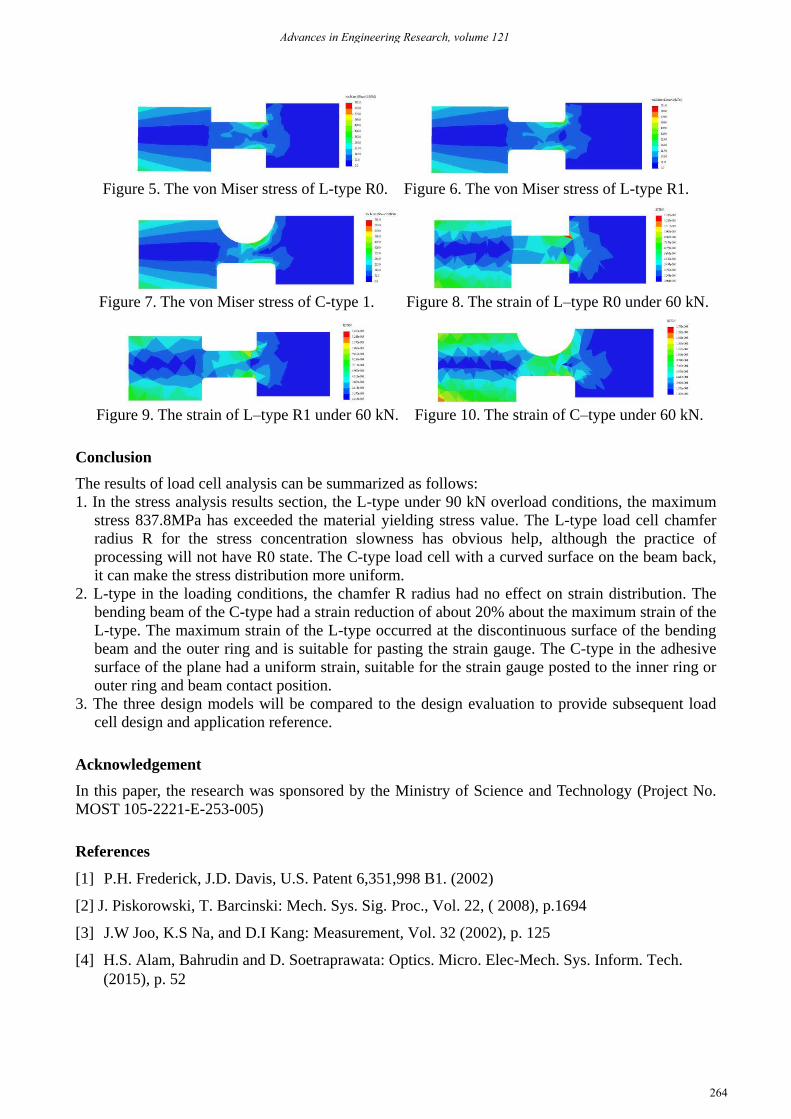
Figure 5. The von Miser stress of L-type R0. Figure 6. The von Miser stress of L-type R1.
Figure 7. The von Miser stress of C-type 1. Figure 8. The strain of L–type R0 under 60 kN.
Figure 9. The strain of L–type R1 under 60 kN. Figure 10. The strain of C–type under 60 kN.
Conclusion
The results of load cell analysis can be summarized as follows:
1. In the stress analysis results section, the L-type under 90 kN overload conditions, the maximum
stress 837.8MPa has exceeded the material yielding stress value. The L-type load cell chamfer
radius R for the stress concentration slowness has obvious help, although the practice of
processing will not have R0 state. The C-type load cell with a curved surface on the beam back,
it can make the stress distribution more uniform.
2. L-type in the loading conditions, the chamfer R radius had no effect on strain distribution. The
bending beam of the C-type had a strain reduction of about 20% about the maximum strain of the
L-type. The maximum strain of the L-type occurred at the discontinuous surface of the bending
beam and the outer ring and is suitable for pasting the strain gauge. The C-type in the adhesive
surface of the plane had a uniform strain, suitable for the strain gauge posted to the inner ring or
outer ring and beam contact position.
3. The three design models will be compared to the design evaluation to provide subsequent load
cell design and application reference.
Acknowledgement
In this paper, the research was sponsored by the Ministry of Science and Technology (Project No.
MOST 105-2221-E-253-005)
References
[1] P.H. Frederick, J.D. Davis, U.S. Patent 6,351,998 B1. (2002)
[2] J. Piskorowski, T. Barcinski: Mech. Sys. Sig. Proc., Vol. 22, ( 2008), p.1694
[3] J.W Joo, K.S Na, and D.I Kang: Measurement, Vol. 32 (2002), p. 125
[4] H.S. Alam, Bahrudin and D. Soetraprawata: Optics. Micro. Elec-Mech. Sys. Inform. Tech.
(2015), p. 52
Advances in Engineering Research, volume 121
264