using load cells - hidroteka · page 5/48 nt-using load cells-e-0110 2 - principle of load cells...
TRANSCRIPT

Using load cells Mounting guide
for load cells
Weighing technology

Page 2/48 NT-Using Load cells-E-0110
SCAIME SAS
ZI de Juvigny, BP501 74105 Annemasse – France Tel. (+33) 4 50 87 78 64 Fax. (+33) 4 50 87 78 46
http://www.scaime.com/

Page 3/48 NT-Using Load cells-E-0110
Summary
1 – Introduction ………………………………………………………. 4
2 – Principle of load cells ……………………………………………..… 5 2.1 - About load cells 2.2 - Strain gauges and load cells 2.3 - Wheatstone Bridge circuit
3 – Type of load cells …………………………………………………...… 7 3.1 - Bending beam load cells 3.2 - Shear beam load cells 3.3 - S-type load cells 3.4 - Column compression load cells 3.5 - “Pancake” compression load cells 3.6 – Single points load cells 3.7 – Load pins
4 – Load cells specifications ………………………………………...… 17 4.1 - Accuracy specifications in legal metrology 4.2 - capacity specifications 4.3 - metrological specifications 4.4 - Electrical specifications 4.5 - Environmental protection level
4 - Tank weighing …………………………………………….……..… 21 5.1 - Compression versus tension 5.2 - Weighing system performance 5.3 - How many load cells ? 5.4 - Weighing system capabilities 5.5 - Load cells location 5.6 - Load introduction 5.7 - Structural integrity 5.8 - Pivoted Weighing Systems 5.9 - Additional restraint methods 5.10 - Piping connections 5.11 - Environmental factors 5.12 - Calibration
6 – Electrical wiring …………………………………………………...… 37 5.1 – general considerations 5.2 - 4-wire/6-wire load cells 5.3 - Multiple load cells connection 5.4 - Cable extension 5.5 - Grounding
7 - Load cell troubleshooting …………………………………...… 40
8 - Annexes ……………………………………………………………… 43 A1 - DO’S & DONT’S of load cells A2 - Ingress protection under EN60529 (IP system) A3 - Ingress protection under DIN40050 (IP69K) A4 - Safety instructions

Page 4/48 NT-Using Load cells-E-0110
1 - Introduction
The purpose of this guide is to give you an overview of load cells types and to assist you in designing the most efficient and effective weighing system for your specific requirements.
Load cells are designed to sense force or weight under a wide range of adverse conditions; they are not only the most essential part of an electronic weighing system, but also the most vulnerable.
In order to get the most benefit from a load cell, the user must have a thorough understanding of the technology, construction and operation of this unique device. In addition, it is imperative that the user selects the correct load cell for the application and provide the necessary care for the load cell during its lifetime.
Load cell selection in the context of trouble free operation concerns itself primarily with the right capacity, accuracy class and environmental protection. it should also be recognized that a particular measuring principle might offer distinct advantages in terms of overload capabilities or the ease of mounting.
If, at any time during the designing stages of your weighing system, you have any questions, please feel free to call us for assistance. At SCAIME, we’re committed to providing you exactly what you need, when you need it.
Symbols used in this Manual
The following symbols and type styles may be used in this manual to highlight certain parts of the text :
• Warns of a potentially dangerous situation: failure to comply with instructions could lead property damage and/or physical injury.
• Indicate an helpful information: Means that advise or important information about the
product or its handling is being given.
Page 5/48 NT-Using Load cells-E-0110
2 - Principle of load cells
2.1 - About load cells
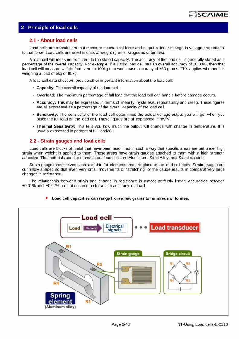
Load cells are transducers that measure mechanical force and output a linear change in voltage proportional to that force. Load cells are rated in units of weight (grams, kilograms or tonnes).
A load cell will measure from zero to the stated capacity. The accuracy of the load cell is generally stated as a percentage of the overall capacity. For example, if a 100kg load cell has an overall accuracy of ±0.03%, then that load cell will measure weight from zero to 100kg to a worst case accuracy of ±30 grams. This applies whether it is weighing a load of 5kg or 95kg.
A load cell data sheet will provide other important information about the load cell:
• Capacity: The overall capacity of the load cell.
• Overload: The maximum percentage of full load that the load cell can handle before damage occurs.
• Accuracy: This may be expressed in terms of linearity, hysteresis, repeatability and creep. These figures are all expressed as a percentage of the overall capacity of the load cell.
• Sensitivity: The sensitivity of the load cell determines the actual voltage output you will get when you place the full load on the load cell. These figures are all expressed in mV/V.
• Thermal Sensitivity: This tells you how much the output will change with change in temperature. It is usually expressed in percent of full load/°C.
2.2 - Strain gauges and load cells
Load cells are blocks of metal that have been machined in such a way that specific areas are put under high strain when weight is applied to them. These areas have strain gauges attached to them with a high strength adhesive. The materials used to manufacture load cells are Aluminium, Steel Alloy, and Stainless steel.
Strain gauges themselves consist of thin foil elements that are glued to the load cell body. Strain gauges are cunningly shaped so that even very small movements or “stretching” of the gauge results in comparatively large changes in resistance.
The relationship between strain and change in resistance is almost perfectly linear. Accuracies between ±0.01% and ±0.02% are not uncommon for a high accuracy load cell.
Load cell capacities can range from a few grams to hundreds of tonnes .

Page 6/48 NT-Using Load cells-E-0110
2.3 - Wheatstone Bridge circuit
The strain gages, usually four or a multiple of four, are connected into a Wheatstone bridge configuration in order to convert the very small change in resistance into a usable electrical signal.
Load cells usually have 4 or 6 wires coming out of them. Two of these wires are to power the load cell. This is called “excitation”. Two of the other wires return a signal to the weight indicator. These are called “signal” wires. If the load cell has a 6-wire connection, the extra 2 wires are called “sense” wires. These are used by the weight indicator to compensate for voltage drop in the excitation over long distances. The sense wires are connected to the same point as the excitation wires.
If the gages within a load cell are connected in a balanced Wheatstone Bridge circuit, and are excited by a source of AC or DC voltage, the transducer will produce an electrical output which is a direct linear function of the excitation voltage.
Load cells usually have an excitation voltage of between 3 and 15 Volts DC. The signal output of the load cell depends on the load cell itself, but it is usually in the range of 0 to 50 mV.
The signal output of the load cells is expressed in milli-Volts per Volt (mV/V). What this means is that for every Volt of excitation applied to the load cell, it will output so many milli-Volts at full scale. This value is called the load cell’s sensitivity . Typical sensitivity ranges are from 1mV/V to 3 mV/V.
In this example:
• A load cell has a capacity of 2kg and a sensitivity of 2mV/V.
• The weight indicator has an excitation voltage of 5Vdc.
• The output signal when a 2 kg weight is applied on the load cell is 10mV.

Page 7/48 NT-Using Load cells-E-0110
3 – Type of load cells
3.1 - Bending beam load cells
3.1.1 - Principle
Bending as a measuring principle offers excellent linearity. Bending beams high strain levels at relatively low forces with greater deflection compared to other measuring principles. This in turn means that although the cell is subjected to greater static overload, mechanical stops are more feasible. The dynamic overload capabilities are excellent because of the typical high deflection.
Bending beams are used in platform scales, weighing small hoppers, belt weighers and weigh feeders and other high precision applications.
Bending beam load cells are commonly used in capaci ties from around 5kg to 1,000kg.
3.1.2 - F60X bending beam load cell
The most common type available is the all stainless steel F60X which is sealed to a very high integrity (IP 68). This makes them extremely suitable for wash-down situations such as food processing plants.
3.1.3 - Load introduction
Loads should be introduced as closely as possible in the direction of measurement. Torsion moments, off-centre loads and transverse or lateral forces cause measurement errors and are liable to damage the load cell. These adverse influences must be avoided, e.g. by using stay rods or guide rolls. These elements must not absorb any load or force components in the direction of measurement (force shunt resulting in measurement errors).
The following must be considered with attention:
• The load cell and especially the thin-walled bellow s must be handled with care.
• Do not overload the load cell, not even for a short time. When handling and mounting load cells with small rated capacities, you will re ach permissible limit values quickly.
• The load cell seating must be horizontal, flat over the whole surface and, like the load cell base, absolutely clean.
• Never load in a direction opposite to the load dire ction specified (see data sheet).
• Load cells are to be clamped in tightly at the moun ting bores, like a cantilever beam. Refer to the data sheet for the recommended tighten ing torques.

Page 8/48 NT-Using Load cells-E-0110
SCAIME offers different load-introduction components suiting various mounting situations in order to minimize the adverse effects due to load introduction or environmental factors.
• LFC, LFD : Swivel foot designed for platform scales manufacturing
• MTPFA : Roll and ball joint tension mounting kit. Designed for suspended hoppers weighing and mechanical weighbridge modernization.
• RUBBERKIT : Compression mounting kit including elastomer for misalignment compensation and vibration or shock absorption. Designed for small tanks or hoppers weighing with agitator.
• STABIFLEX : Compression mounting kit including built-in side stoppers, lift-off prevention and high precision ball and cup de-coupling. Designed for tanks or hoppers weighing.
3.2 - Shear beam load cells
3.2.1 - principle
Shear beam load cells are especially suited for all types of medium and high capacity weighing applications. This load cell is bolted to a fixed structure at one end and force is applied through a single point at the other end, causing the beam to bend and placing the strain gauge area under shear.
Shear as a measuring principle offers a good resistance against side loads and small sensitivity to the variation of loading position.
Along the beam centre line, the shear stress is ind ependent of the point of load application
They are most commonly used in conjunction with special swivel feet and mounted in the corners of large platform scales. They are also used for vessel weighing.
In comparison with bending beam load cells, they offer:
• Better independence with respect to the point of load application. • Better resistance to side forces. • Better overload capability.
Although mechanical stops are more difficult to adjust because of limited deflexion at full scale.
Shear beam load cells are commonly used in capaciti es from around 300kg to 5,000kg.

Page 9/48 NT-Using Load cells-E-0110
3.2.2 - SK30X shear beam load cell
SCAIME offers the all stainless steel SK30X which is sealed to a very high integrity (IP 68). This makes them extremely suitable for wash-down situations and sanitary environments such as dairies and food processing plants.
3.2.3 - Load introduction
Loads should be introduced as closely as possible in the direction of measurement. Torsion moments, off-centre loads and transverse or lateral forces cause measurement errors and are liable to damage the load cell. These adverse influences must be avoided, e.g. by using stay rods or guide rolls. These elements must not absorb any load or force components in the direction of measurement (force shunt resulting in measurement errors).
SCAIME offers different load-introduction components suiting various mounting situations in order to minimize the adverse effects due to load introduction or environmental factors.
• LFA, LFD : Swivel foot designed for platform scales manufacturing
• ISOFLEX : Compression mounting kit including elastomer for misalignment compensation and vibration or shock absorption. Designed for tanks or hoppers weighing with agitator.
• STABIFLEX : Compression mounting kit including built-in side stoppers, lift-off prevention and high precision ball and cup de-coupling. Designed for tanks or hoppers weighing.

Page 10/48 NT-Using Load cells-E-0110
3.3 - S-type load cells
3.3.1 - principle
The S-type Load cell is most commonly used in tension (but can be used in compression).The S-type Load cell is use bending or shear as a measuring principle. It must be arranged so that the force applied passes perpendicularly through the centre of the load cell. To ensure this happens, most end users fit clevis pins or rod-end bearings to the load cell to movement which copes with expansion forces and other miss-alignment.
S-type Load cells are used for vessel weighing, tensile testers, torque restraints and other applications.
S-type load cells are commonly used in capacities f rom around 25kg to 5,000kg.
3.3.2 - ZA30X S-type load cell
SCAIME offers the all stainless steel ZA30X which is sealed to a very high integrity (IP 68). This makes them extremely suitable for wash-down situations and sanitary environments such as chemical processing plants.
3.3.3 - Load introduction
The threaded boreholes at the top and bottom are used for the load introduction. Loads should be introduced as closely as possible in the direction of measurement. Torsion and bending moments causes measurement errors and are likely to damage the load cell. These adverse influences must be avoided by construction elements which are not absorb any load in the direction of measurement.
SCAIME offers knuckle eyes to minimize adverse effects due to load introduction :
• The nuts of the knuckle eyes must be fastened at max. load.
• Do not introduce the fastening torque through the load cell.
When utilizing tension cells for vessel weighing:
• Position the load cells around the tank so that each will support an equal weight.
• Make sure that the upper and lower rod end are turned at 90 degrees to each other. This will reduce swaying.
• Install a safety rod next to each weigh module
• make sure that load cell is hanging vertically
• If the suspended tank is subject to horizontal movement, install check rods to limit horizontal movement.
It is of prime importance to apply the force axiall y to the load cell.
Page 11/48 NT-Using Load cells-E-0110
3.4 – Column compression load cells
3.4.1 - Principle
Although conceptually simple, the column element has a number of specific characteristics which makes these load cell types difficult to design and produce. The column itself should be long enough, with respect to its cross section, to provide a uniform strain field. Column load cells are inherently non-linear while deforming under load. This non-linearity is compensated with semiconductor gages.
Compression type load cells don't suffer from the momentum typically associated with beams. The ultimate overload capabilities are therefore excellent. However, the relatively small deflection makes this load cell type more sensitive to shock loading.
Column load cells offer high accuracy, so they are often used in truck scales and vessel weighing when high accuracy is required.
Compression column load cells are commonly used in capacities from around 5t to 200t.
3.4.2 – CB50X compression column load cell
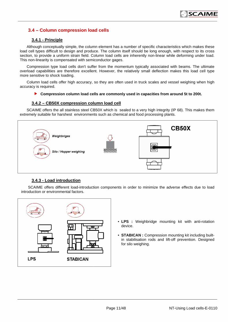
SCAIME offers the all stainless steel CB50X which is sealed to a very high integrity (IP 68). This makes them extremely suitable for harshest environments such as chemical and food processing plants.
3.4.3 - Load introduction
SCAIME offers different load-introduction components in order to minimize the adverse effects due to load introduction or environmental factors.
• LPS : Weighbridge mounting kit with anti-rotation device.
• STABICAN : Compression mounting kit including built-in stabilisation rods and lift-off prevention. Designed for silo weighing.

Page 12/48 NT-Using Load cells-E-0110
3.4.4 – Installation in weighbridge applications
The CB50X is a pendulum load cell designed to automatically restore the mounting construction to a stable initial position in the case of a small lateral displacement of the load introduction. This assembly, ideally suited for weighbridge applications allows free motion in any direction in the horizontal plane.
• Install and adjust appropriate stops .
• The base and load plates should be seated on a steel plates. These mounting surfaces must have a flatness <2/1000 and an horizontality <4/1000.
• Load cells must be placed in an upright position an d on the same horizontal level.
• The maximum permissible lateral displacement or slo pe must not be exceeded
• The plates should be aligned in such way that the flat part of the rotation-stop device is parallel to the main traffic direction on the weighbridge .
• to protect the bearing surfaces from wear, tear, and dirt, clean and grease the elements .
• To avoid the clogging of the rotation-stop device, it’s better to place the rotation-stop in high position.
• Use an appropriate bubble level to check the load cell’s perpendicular mounting position.
• Align load cells vertically with a bubble level .

Page 13/48 NT-Using Load cells-E-0110
3.5 – “Pancake” compression load cells
3.5.1 - Principle
The deflection of the load cell by the load is measured by the foil gage sensor, which is entirely sealed within a cavity inside the transducer. The sensor converts the deflection into an electrical signal which is directly proportional to the increase or decrease of the load. Unwanted side loads will not affect the accuracy.
The “pancake” load cell are less accurate compared to column compression load cells but the measuring principle allows a very low profile design making them ideal for silo or vessel weighing. The low-profile design for low clearance installations also keeps the vessel’s centre of gravity low and stable. Installation is simplified with less hardware than column load cells.
Compression “Pancake” load cells are used in capaci ties from 5t to 750t, and more…
3.5.2 – R10X compression pancake load cell
SCAIME offers the all stainless steel R10X which is sealed to a very high integrity (IP 68). This makes them extremely suitable for measuring bulk material in the sanitary and clean-in-place environments.
3.5.3 - Load introduction
SCAIME offers mounting kits in order to minimize the adverse effects due to load introduction or environmental factors.
• SILOKIT-R : Compression low profile mounting kit including built-in stabilization plate and lift-off prevention. Designed for silo weighing.

Page 14/48 NT-Using Load cells-E-0110
3.6 – Single points load cells
3.6.1 - Principle
Single Point Load cells probably account for the largest percentage of all load cells in existence world wide. They are the heart of most small bench-top scales and are also used in a wide range of other applications. Single point load cells use bending as a measuring principle.
“Single Point” is really a bad name for these load cells. “Platform” load cells would be far more applicable:
What makes them different from all the load cells discussed so far, is that the load does not need to be applied through a single mounting point on the load cell. Instead, a single point load cell will accept a platform of specified dimensions (“Max. platform size” on specification sheet) that can be bolted directly to the load cell. The load can then be applied to any point on that platform and the load cell will measure it accurately.
Usual capacities range from 1kg to 1000kg.
3.6.2 – AG single point load cell
SCAIME offers a comprehensive range of single point load cell from 200g to 1500kg. Our range comes from low cost aluminium load cells for bench scales applications up to fully welded stainless steel load cells suitable for platform scales used in corrosive or wash down environment.
The most common type available is the AG load cell, ideally suited for single load cell platform construction.
3.6.3 - Load introduction
You can see on the following sketch, a typical single point load cell used in platform scale application.
• Install and adjust appropriate overload stops to pr otect the load cell.
• Never load in a direction opposite to the load dire ction specified (see data sheet).
• Platform size must be less than “Maximum platform s ize” (see data sheet).
• Load cells are to be clamped in tightly at the moun ting holes, like a cantilever beam. Refer to the data sheet for the recommended t ightening torques.

Page 15/48 NT-Using Load cells-E-0110
3.7 – Load pins
3.7.1 - Principle
A load measuring pin senses the force applied across it, via strain gauges installed within a small bore through the centre of the pin. Two grooves are machined into the outer circumference of the pin to define the shear planes, which are located between the forces being measured.
Load measuring pins are designed for many diverse applications as direct replacements for clevis or pivot pins. They have many advantages over other load sensors in that they do not normally require any change to the mechanical structure being monitored.
Usual capacities range from 20kg to 100t.
3.7.2 – M16 load pin
The most common type available is the M16, ideally suited for load measurement and overload protection on cranes, hoists, fork lift trucks and winches.
3.7.3 – Typical locations
If a pin exists within a defined load path or can be fitted to experience a force, then an M16 Load Pin can be installed to monitor that load. The sketches below show typical locations for load pins.

Page 16/48 NT-Using Load cells-E-0110
3.7.4 - Load pin locking systems
A load-measuring pin needs to be locked into position in order to fix its orientation. This needs to be fixed, both in the axial and rotation modes, to ensure accurate results are obtained from the in-built locking system.
Slide manually the load pin into its seat. Never use a hammer or other tool to insert it.
3.7.5 – Measuring force calculation
A standard load pin is designed to sense the force in one direction only. Be careful with the load pin mounting position to avoid measurement errors.
Resultant force measured by the load pin
Beware of the resultant force measured by the load pins, which can be different from the load applied on the wire.
The resultant force can be multiplied or reduced according to the mounting.
Error due to the change in load direction
The load pin measurement direction should be in the same direction than the resultant force, otherwise a measurement error (% of the applied load) could be calculated by :
error (%) = 100 (cos αααα –1)
3.7.6 – Mounting considerations
The load pin must be free to bend over its support. For this, you need to check that:
• g ≥ 0.01 x b (usually: g ≥ 0.2mm)
• Leave a gap (~0,2mm) between the locking system and the load pin mortise. Thus no strain can be transmitted through locking system.
• For a better accuracy, the sensor should bear no radial effort or torque.
• to avoid any torque effects, the load must be free to rotate around the pin (use antifriction elements or bearings).

Page 17/48 NT-Using Load cells-E-0110
4 - Load cells specifications
All the following definitions will help you to understand the load cell data sheets.
4.1 – Accuracy specifications in legal metrology
This part covers load cell accuracy grades according to the OIML. It will also cover key terminology and metrological terms which are used by load cell and scale manufacturers.
Legal Metrology is the entirety of the legislative, administrative and technical procedures established by public authorities in order to ensure, in a regulatory manner, the appropriate quality of measurements related to official controls, trade, health, safety and the environment.
Several organizations set standards for the weighing industry and provide load cells requirements to ensure the accuracy of scales.
• In Europe , test certificate is given by EEC (European Economic Community) notified body according to recommendations set by the OIML (Organisation Internationale de Métrologie Légale).
The OIML is an intergovernmental treaty organization. It was established in order to promote the global harmonization of legal metrology procedures. The OIML provides its Members with metrological guidelines for the elaboration of requirements concerning the manufacture and use of measuring instruments.
A manufacturer can obtain an OIML Certificate indicating that an instrument complies with the requirements of the relevant OIML International Recommendations.
• OIML R60 : guidelines regarding load cells requirements.
• OIML R76 : guidelines regarding Non Automatic Weighing Instrument (NAWI).
Accuracy class
• Weighing instruments are tested and certified according to OIML R76 (EN45501), class III covers the commercial weighing applications between 500 and 10,000 divisions.
• Load cells are tested and certified according to OIML R60.
• Load cells are ranked, according to their overall performance capabilities. A load cell is classified by a letter (A to D) and the maximum number of load cell intervals (n LC), stated in units of 1000; for example C3 represents class C with 3000 load cell intervals.
• Class C load cells are suited for class III and IIII weighing systems.

Page 18/48 NT-Using Load cells-E-0110
Maximum permissible error (mpe)
Figure above shows the maximum permissible error (mpe) depending on number of verification intervals:
• for a weighing instrument in class III (OIML R76). • for a load cell in class C with a pLC=0,7 (OIML R60).
The pLC fraction (0,7 by default) represent the apportionment error attributed to a load cell.
Minimum verification interval (v min )
It’s the smallest value of a quantity (mass) in which the load cell measuring range can be divided without exceeding the maximum permissible error.
Minimum dead load output return (DR) The difference in load cell output at minimum dead
load, measured before and after a 30 minutes load application (>90% of the load cell capacity ).
Creep error Deviation of load cell output occurring with time
while under constant load
4.2 - capacity specifications
Minimum dead load (Emin)
The smallest value of a quantity ( mass ) which may be applied to a load cell without exceeding the “mpe”.
Maximum capacity (E max)
The largest value of a quantity which may be applied to a load cell without exceeding the “mpe”.
• Load cell measuring range : Lawful operational range of the load cell delimited by Emin and Emax.
• Rated capacity : Value of load which may be applied to obtain an output voltage equal to the rated sensitivity. This load is often equal to Emax.
Safe load limit (E lim )
The maximum load that can be applied without producing a permanent shift in the performance characteristics.
Ultimate overload
The maximum load that can be applied without physical destruction of the load cell.

Page 19/48 NT-Using Load cells-E-0110
4.3 - metrological specifications
This section reviews the basic parameters that can be used to specify the accuracy of measurement.
Rated sensitivity
The value obtained by subtracting the unloaded output from the output obtained under rated capacity. Sensitivity is expressed by the value of the output voltage by unit of excitation voltage.
Combined error
In absence of any influence factors, the relationship between the load cell output signal ,and the applied load will be a continuous curve exhibiting some non-linearity and hysteresis. The maximum output deviation between the calibration curve and the ideal straight line calibration is the combined error.
• Non-linearity: The deviation of the increasing load cell calibration curve from a straight line which passes through minimum load output and the load cell output at the rated capacity.
• Hysteresis: The difference between load cell output readings for the same applied load, one reading obtained by increasing the load from minimum load and the other by decreasing the load from nominal capacity.
Temperature effect
• Compensated temperature range : The temperature range in which the output signal and zero balance are compensated to not be affected by an error exceeding the maximum permissible.
• Service temperature range : The temperature range in which the load cell can be operated without causing permanent change in its properties.
• Temperature effect on zero : The change in minimum dead load output due to a change in ambient temperature.
• Temperature effect on sensitivity : The change in sensitivity due to a change in ambient temperature.

Page 20/48 NT-Using Load cells-E-0110
4.4 - Electrical specifications
Electrical resistance
• Input resistance : Resistance measured across the input terminals with the output terminals opened under the no-load condition.
• Output resistance : Resistance measured across the output terminals with the input terminals opened under the no-load condition.
• Insulation resistance : Direct current resistance measured between the circuit for a load cell ands its casing, under testing conditions of 50 VDC.
Nominal range of excitation voltage
Range of excitation voltage, DC or AC, for which the result of measurement should not be affected by an error exceeding the load cell specifications.
4.5 - Environmental protection level
No standard have been developed to cover load cells suitability for environmental conditions. In the absence of such standards, some load cells characteristics should be reviewed to determine the load cells suitability for specifics conditions:
IP protection class (EN60529)
The IP standard describes the degree of protection provided by the enclosures of electrical equipment against the ingress of solid foreign objects and against ingress of water.
While the IP standard is an acceptable starting point, some shortcomings are noticed:
• IP system can not clearly differentiate between load cells with different constructions. • IP system don't deal with internal condensation or moisture within the enclosure.
Load cells sealing method
• Potted : Refers to load cell which is environmentally sealed by a protective coating or by filling the strain gauge cavity with a material that protects the gauges from environmental hazards such as moisture. These load cells are normally used for indoor applications.
• Enclosed : Refers to load cells which have a strain gauge cavity filled with a potting compound. The cavity is also mechanically protected with side plates. These cells are protected from normal environmental factors in indoor or outdoor applications.
• Hermetically sealed : Refers to load cells which have a metallic protective cover welded to protect the strain gauge cavity. These load cells provide the best protection in harsh chemical or wash down environments.
A word of caution
stainless steel load cells are not synonymous with hermetically sealed load cells. While enclosed stainless steel load cells may be suitable for dry chemical corrosive environments, hermetically sealed stainless steel models are the appropriate choice for high moisture or wash down applications.

Page 21/48 NT-Using Load cells-E-0110
5 - Tank weighing
Load cells may be used to weigh tanks, hoppers or vessels in various installation configurations. The installation of load cells into a practical field application requires following several basic rules as well as careful design attention if the system has to be accurate and provide a long, maintenance free span of operation.
5.1 - Compression versus tension
Load cells measure force in one of two directions; tension or compression. The use of a tension or compression system depends upon the mechanical structure around the vessel and the ease of creating the system.
5.1.1 – Compressive mode
In the compressive mode a vessel is supported by load cells. If a vessel must be placed on an open concrete pad, compression will be a logical way to operate, because a tension system would require an expensive additional overhead supporting structure.
To help load cell mounting, SCAIME offers compression mounting kits especially designed for tank weighing. A typical compression mounting kit includes a top plate (which receives the load), and base plate (which is bolted to the floor or other support surface). Some kits provide also additional devices (see data sheet) as :
• A hold-down bolt used to prevent the vessel from tipping. • Stay rod or limiting stops for eliminating unwanted side forces • Elastomer dumper for shock or vibration absorption

Page 22/48 NT-Using Load cells-E-0110
5.1.2 – Tensile mode
In the tensile mode the vessel is suspended from one or more load cells. if a suitable structure for a tension application is available, it is usually easier, and less costly to suspend the vessel up to a vessel capacity of 10 tons. When the vessel capacity exceeds this value there is more cost involved in making the required hardware than providing an adequate base for compression assemblies.
• In theory, suspension of a vessel by a single load cell may be the ideal solution, but such tension installations are not usually feasible.
• Three of four point supports are the most commonly used configurations.
5.2 - Weighing system performance
Accuracy, resolution, and repeatability are basic concepts used to measure a weighing system’s performance.
Resolution is the smallest weight change that a digital scale can detect. Resolution is measured in increment size, which is determined by the capabilities of the load cells and digital indicator. A digital weight indicator may be able to display a very small increment size, such as 0.01 kg (resolution); however, that does not mean the system is accurate to 0.01 kg.
Accuracy is how close the reading on a scale’s indicator is to the actual weight placed on the scale. A scale’s accuracy is usually measured against a recognized standard, such as certified test weights.
Repeatability is a scale’s ability to display a consistent weight reading each time the same weight is placed on the scale. It is especially important for batching and filling applications, which require that the same amount of a material be used for each batch.
Repeatability and accuracy go hand in hand. You can have a repeatable system that is not accurate, but you cannot have an accurate system unless it is repeatable.
The following factors can influence the accuracy and repeatability of a weighing system. They are discussed in detail later in this guide :
• Load cells factors : Type, Number, capacity, specification (see chapter 4)
• Mechanical factors : Tank design, Support Structures, Piping Design
• Environmental Factors : Wind, Temperature, Vibration
• Calibration
Page 23/48 NT-Using Load cells-E-0110
5.3 - How many load cells ?
The number of load cells to support a vessel is usually fixed by the design of the tank. The most ideal situation is to support a vessel by 3 load cells. If a weighing tank is supported by 4 or more load cells, 3 or in the worse case only 2 load cells will bear the total weight. In this case, an overload situation on these cells might occur. By measuring the output of every individual load cell, such a situation can be recognized and corrected by placing shim plates underneath the cells with minor output
The load cells should be positioned in such a way t hat each load cell will bear the same amount of weight
Applied load calculation
Load cells must resist to the total applied load in normal and exceptional conditions.
The minimum load cell capacity, C LC must satisfy:
(((( ))))
NCTareQ
Clive
LC++++××××≥≥≥≥ where Tare : Tare or dead load (kg)
Clive : Live load, maximum weight applied (kg) Q : safety factor N : number of load cells
Safety factor Q
It doesn’t exist rules to define factor Q which usually depend from the following environmental conditions :
• Eccentric loading conditions • Shocks and dynamic load • Wind forces • Load receptor design
Some examples for information : Q
4 load cells platform scale 1,8 Indoor vessel 1,3 Vessel with agitator 1,7 Weighbridge 2 1 load cell platform scale 1,4
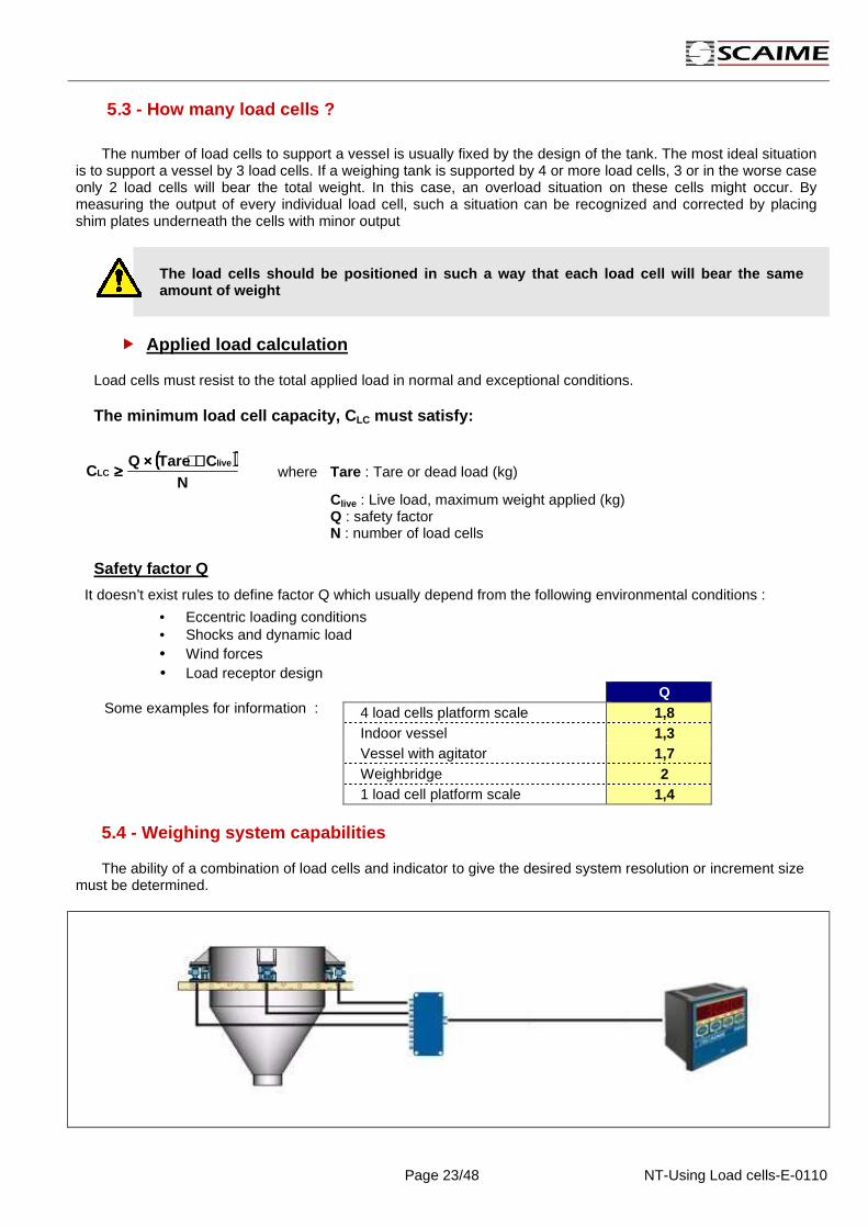
5.4 - Weighing system capabilities
The ability of a combination of load cells and indicator to give the desired system resolution or increment size must be determined.

Page 24/48 NT-Using Load cells-E-0110
5.4.1 – System resolution
the desired system resolution or increment size can be determined by the following formula:
Signal by increment (µV) =
Desired Increment Size × Load Cell Sensitivity (mV/V) × Excitation Voltage (V) × 1 000
Individual Load Cell Capacity × Number of Load Cells
Enter the desired increment size into the formula, along with the load cell and indicator parameters. If the signal by increment (µV) exceeds the minimum allowed for the indicator, the system should be able to deliver the desired resolution.
Example
Suppose a tank scale has four 5 000 kg load cells (2 mV/V) attached to an IPE50 indicator. You want to be able to weigh up to 15 000 kg at 2 kg increments (7,500 displayed increments).
Use the formula to determine the required signal by increment : µVkg
VDCVmVkg1
4500010005/22
====××××
××××××××××××
The minimum allowable signal by increment for an IPE50 is 0.3µV microvolt per increment. Since the 1 µV signal derived from the formula is above this 0.3 µV, you should be able to display 2 kg increments.
5.4.2 - Excitation voltage
In a measuring chain, the excitation voltage provided by the transmitter must be adequate to supply load cells in current.
Weighing system resistance ΩΩΩΩN
RZ
LC==== where RLC : load cell input resistance
N : number of load cells
The indicator must provide a current (A) Z
UI
excexc = where Uexc : load cells excitation voltage
it must be checked Z > R min or I exc < Imax with R min : minimum resistance of transmitter Imax : maximum current of transmitter

Page 25/48 NT-Using Load cells-E-0110
5.5 - Load cells location
The 2 most common places that load cell assemblies are mounted, are:
Under the vessel’s legs.
Between a gusseted bracket and a mezzanine floor.
Mounting the assemblies under the legs is perfectly acceptable. However, the second case is the best one, due to the natural stability offered by a low centre of gravity.
Some example of load cells location
Vessel with mixer
Eccentric vessel with gravity center variation
5.6 - Load introduction
Load cells that use strain gauges are sensitive enough to detect very small changes in weight. The trick is to make sure that they react only to the weight you want to measure, not to other forces. To get accurate weight readings, you must carefully control how and where weight is applied.
The center of gravity under empty or full load must keep in the load cells basis of support.

Page 26/48 NT-Using Load cells-E-0110
a load cell should be installed so that the load is applied vertically throughout the entire weight range .
To attain that ideal, the load cell support would need to be level, parallel, and rigid.
Loading force problems
When the load cell is not installed properly, there are several types of forces that can affect its accuracy.
• Angular loading occurs when a force that is not perfectly vertical is applied to a load cell.
• Eccentric loading occurs when a vertical force is applied to a load cell at a point other than its centre line. This problem can be caused by thermal expansion.
• Side and end loading occur when horizontal forces are applied to the side or end of a load cell. They can be caused by thermal expansion, by misalignment, or by movement due to dynamic loading.
• Torsional loading occurs when a side force twists a load cell. It can be caused by structural deflection, system dynamics, thermal movement, or misalignment.
• Top support and base support should be aligned and levelled
• Top support and base support should not deflect more than 0.5°
• The centre line (CL) of the load on the cell should align to the centre line of the support to prevent structure deflection .
The weight error will increase with the angle at which the support is leaning : (((( )))) weightangle
Error ××××−−−−====cos
11

Page 27/48 NT-Using Load cells-E-0110
5.7 - Structural integrity
It is a common misconception that a load cell can be considered as a solid piece of metal on which vessels, silos or hoppers can be supported. The performance of a load cell depends primarily on its ability to deflect under highly repeatable conditions when load is applied or removed.
5.7.1 - Support structure design
Metal support structures tend to bend or deflect as the amount of weight placed on them increases. Too much deflection can affect the accuracy of a tank scale
• Mounting load cells at mid-span of the support beams will cause the most deflection on the beams at high loads.
• A better way to reduce deflection is to mount weigh modules near grounded vertical columns. Be sure to support all cells with the same size structural beams to prevent differential deflection.
Reinforcement to the support beams is recommended t o minimizing deflection
• Figure 1 shows how a support beam can deflect when a weigh module is mounted at mid-span. If this type of arrangement cannot be avoided, you should reinforce the support beams to minimize deflection.
• Figure 2 and 3 show typical reinforcement methods.
methods used to mount load cells near grounded vert ical beams
Grounded vertical beam
ISOFLEX mounting kit

Page 28/48 NT-Using Load cells-E-0110
5.7.2 - Structure deflexion
• A tank scale’s structure should deflect as little as possible, and any deflection should be uniform at all support points.
• Support structures and foundation base should be level (+/-0.5 degree) and in the same plane.
Add web stiffeners or gussets if necessary to preve nt the beam from twisting under load.
Reinforced load cell mounting support beam
5.7.3 - Stiffening structures
• In some cases, a tank’s legs will deflect under the weight of the tank. If the deflection is great enough to affect weight readings, you should brace the legs to keep them rigid.
• Use the same support beam sizes to avoid non-uniform deflection.
Web Stiffener
Gusset
STABIFLEX mounting kit

Page 29/48 NT-Using Load cells-E-0110
5.7.4 - Tank interaction
Tanks sharing the same support structure will have an affect on each other’s weighing performance. Any movement and disturbances from one tank is easily transferred to the next tank sharing the same support structure.
• The worst choice is to mount the cells at the mid-span of a horizontal beam, with the two tanks sharing a common support structure. This allows both deflection and vessel interaction.
• best choice is to mount the cells near vertical beams, with a separate support structure for each tank.
5.8 - Pivoted Weighing Systems
In certain applications it is possible to weigh only half the vessel, the other half is supported on dummy load cells or flexure beams acting as pivots.
Pivoted weighing systems can provide an economic method of low accuracy (±1%) level detection system.
There are quite severe restrictions associated with these systems:
• The vessel is symmetrical around a vertical line th rough the content’s centre of gravity.
• The vessel is level and the ends are identical in s hape.
• The vessel is inside and not subject to wind forces .
These restrictions ensure that as the vessel fills, the center of gravity of the contents rises along a vertical line. They also practically limit this sort of application to liquid contents.
In fact not the weight, but the force is measured by the load cell. The force on the load cell(s) can be calculated by :
LFD
Ftotal
LC××××====
The distance between the live and dummy cells (L) should be as long as possible.

Page 30/48 NT-Using Load cells-E-0110
5.9 - Additional restraint methods
Even if most mounting kits provide in-built protection against side forces or lift-off, additional restraint devices must be used in applications with a potential for excessive wind or seismic load forces or when a vibrator or mixer.
These assemblies are designed to allow ample vertical freedom for weight sensing, while simultaneously eliminating side forces.
• Stay rods are used to limit a tank’s horizontal movement so that it will not tip or rotate. They should be positioned at or above the centre of gravity of the full tank.
Lift-off prevention rod must also be used if mounting kits do not provide in-built device.
• Note that the rods are tangential to the tank, with a gap between the nuts on the end of the rods and the brackets on the tank. This enables the rods to restrain the tank while allowing for minor thermal expansion.
Safety rods in tension
Any tank that is suspended by tension weigh modules should have a secondary safety restraint system.
• Fit each safety rod through an oversized hole in the bracket so that the rod does not influence the weight readings.
• Safety rods must be strong enough to support the filled tank in case the primary suspension system fails.
• Horizontal check rods or bumpers can be used around the perimeter of the tank to keep it from swaying.

Page 31/48 NT-Using Load cells-E-0110
5.10 - Piping connections
Any time that piping is connected to a tank scale, there is a potential for mechanical binding. If piping is not installed properly, it can cause weighing errors by pushing or pulling on the tank.
Force exerted by pipe
When the tank is full, it moves downward because of the deflection (∆h) of the load cell and the structure. The pipe exerts a force on the tank, affecting weight measurements. The more flexible the piping is, the less force it will exert on the tank.
the force exerted by pipe is:
(((( ))))
3
446,0L
EhdDFp
××××∆∆∆∆××××−−−−××××====
where: D = Outside diameter of pipe (mm)
d = Inside diameter of pipe (mm)
E = Young’s modulus (for steel: 210.000 N/mm2, for copper: E= 110.000 N/mm2)
• Run all pipes horizontally from the tank. A 90-degree bend in a horizontal run of pipe will make the piping more flexible.
• Use pipe with the smallest diameter and lightest gauge possible. That will make the piping more flexible.
• Use flexible piping or connections whenever possible.
• Locate the first rigid support for the piping as far away from the tank as possible. That will make the piping more flexible.
• When a single discharge pipe is used by adjacent tanks, design the system so that the discharge piping from each tank is supported independently and does not interact with the other tank.
• Do not attach piping to supports for a structure that deflects separately from the tank.
• Instead, attach piping to the tank’s support structure so that the piping moves along with the tank.
Page 32/48 NT-Using Load cells-E-0110
5.11 - Environmental factors
Because environmental factors can affect the accuracy and safety of a weigh system, they must be considered during the design stage.
5.11.1 - Wind or seismic loading
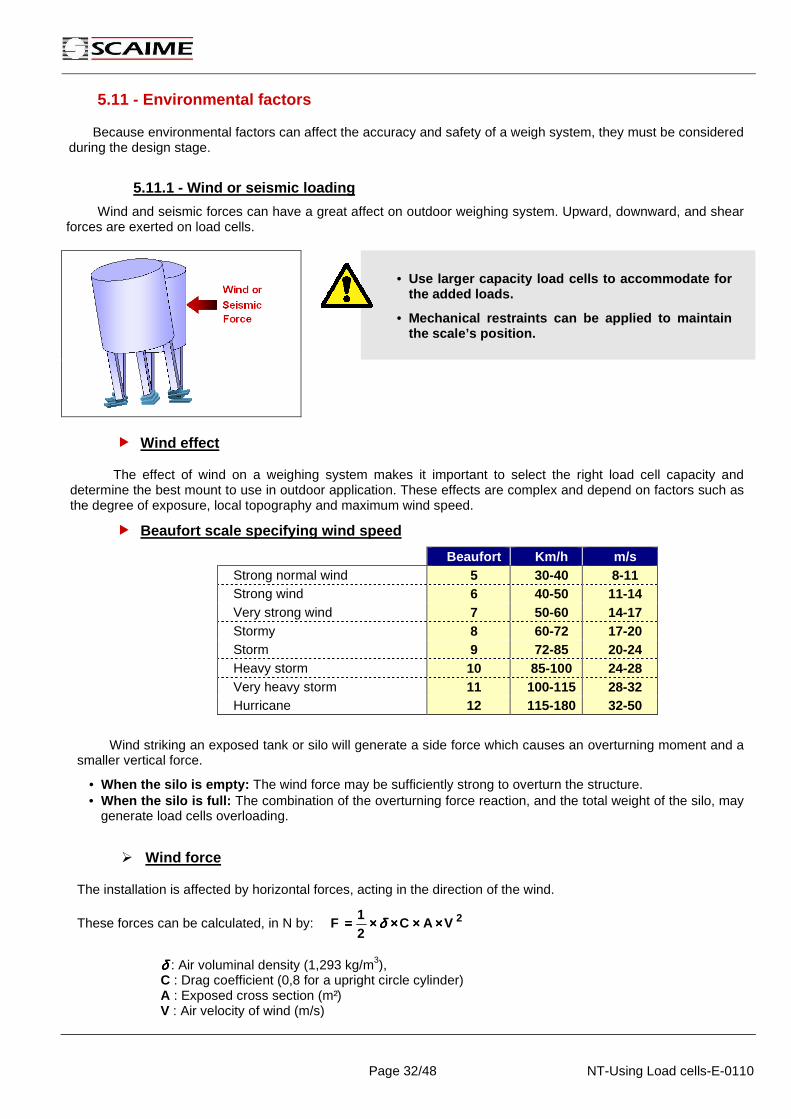
Wind and seismic forces can have a great affect on outdoor weighing system. Upward, downward, and shear forces are exerted on load cells.
• Use larger capacity load cells to accommodate for
the added loads.
• Mechanical restraints can be applied to maintain the scale’s position.
Wind effect
The effect of wind on a weighing system makes it important to select the right load cell capacity and determine the best mount to use in outdoor application. These effects are complex and depend on factors such as the degree of exposure, local topography and maximum wind speed.
Beaufort scale specifying wind speed
Beaufort Km/h m/s Strong normal wind 5 30-40 8-11 Strong wind 6 40-50 11-14 Very strong wind 7 50-60 14-17 Stormy 8 60-72 17-20 Storm 9 72-85 20-24 Heavy storm 10 85-100 24-28 Very heavy storm 11 100-115 28-32 Hurricane 12 115-180 32-50
Wind striking an exposed tank or silo will generate a side force which causes an overturning moment and a smaller vertical force.
• When the silo is empty: The wind force may be sufficiently strong to overturn the structure. • When the silo is full: The combination of the overturning force reaction, and the total weight of the silo, may
generate load cells overloading.
Wind force
The installation is affected by horizontal forces, acting in the direction of the wind.
These forces can be calculated, in N by: 2VAC21
F ××××××××××××××××==== δδδδ
δδδδ : Air voluminal density (1,293 kg/m3), C : Drag coefficient (0,8 for a upright circle cylinder) A : Exposed cross section (m²) V : Air velocity of wind (m/s)

Page 33/48 NT-Using Load cells-E-0110
Example
Specifications
• V = 30m/s
• h = 10m
• d = 3m
• A= hxd
2Vdh8,0293,15,0F ××××××××××××××××××××====
F = 13960 N
Overturning force
The wind force generates a overturning moment, which will be counteracted by a reactive moment of the load cells.
abF
Fov××××====
• Fov : Overturning force caused by wind force
• a : Distance between load cells
• b : height at which the wind force acts
Using the previous calculated wind force of 13960 N and a value for b which is half the height of the silo:
N233003
513960Fov ====
××××====
The overturning force and overloading reaction in kg is: kg23808,9
)Newton(23300Fov ========
Conclusion
• In case of an empty silo:
Uplift protection should be considered if the dead weight of the tank on each load cell is smaller 2380 kg.
• In case of fully loaded silo:
2380 kg must be added to the calculated load cell capacity.

Page 34/48 NT-Using Load cells-E-0110
5.11.2 - Shock loading
A load dropped on the scale from above can exert strong forces that can damage the load cells. Use larger capacity load cells to accommodate for large shock loads and use shock absorbing materials to damp the loading.
• Shock forces caused by dropped weights :
(((( ))))
221
1)21
1 WWW
KHW ++++
++++××××++++++++××××
Where: W1 = Weight being Dropped (kg)
W2 = Dead Weight (kg)
K = Load cell spring rate: rated capacity divided by load cell deflection at rated capacity (kg/m).
H = Height from which Object is Dropped
5.11.3 - Vibration
Caused by the surrounding environment or mixer’s agitation, vibration Induces electrical noise on the load cell’s signal.
• Separate the surrounding structure from the load cell supports.
• Use interior baffles.
• Use isolation pads between the load cells and structure.
5.11.4 - Temperature effects
Temperature can affect a load cell by causing structural supports to expand and contract or by exceeding the operating limits of the load cell. As a tank expands and contracts, it pushes or pulls on attached piping. If the piping connections are rigid, this can cause weighing errors.
• Insulation and low thermal conductive material can be used in between the cells and the tank.

Page 35/48 NT-Using Load cells-E-0110
5.11.5 - Moisture, corrosion and debris
Moisture and corrosive substances can damage the cells physically and by shorting out its electronics. Debris collected on the load cells will cause weighing errors by mechanically binding the scale.
• Provide adequate drainage away from the cells. • Regularly clean accumulated debris. Keep cables clean and in good condition. • Protect cells and cables from corrosive materials.
5.11.6 - Lightning and surge protection
Electrical surges can cause permanent damage to the load cells. Electrical surges may be caused by lightning, large electrical machines or welding.
• Verify the integrity of any existing grounding systems.
• Use a single-point grounding system and surge protection devices.
• Don't carry out electric welding near load cells.
Every load cell should be shunted by a stranded copper cable to prevent welding currents from flowing through the load cell.
5.12 - Calibration
5.12.1 - Calibration preparation
Before calibration, each load cell’s signal output is measured to ensure an even load distribution.
Hang a test weight near one load cell mount and take a reading. Move the test weight to a second load cell, take a reading and repeat for each load cell mount.
The load cells mounts should be shimmed until the signal output from each individual load cell varies less than 25% of each.
The load cells mounts should be shimmed until the s ignal output from each individual load cell varies less than 25% of each.
This applies mainly to vessels with 4 or more load cells. Vessels with 3 load cells that have been levelled, should provide automatic weight distribution. The aim is to get each load cell mount bearing the same amount of weight.
Common sense must prevail however. If the vessel has a large offset load, then the load cell nearest to this will have a higher output. As long as the load cell is not overloaded when the vessel is full, this situation is acceptable.
Build brackets, evenly spaced around the tank to hang test weights.

Page 36/48 NT-Using Load cells-E-0110
When a weighing system is installed, it must be calibrated so that the readings on the indicator accurately reflect the amount of weight placed on the scale. There are 4 main methods used to calibrate weighing system:
5.12.2 - Calibration with test weights
The most accurate, reliable way to calibrate a scale is with test weights. This method is usually limited to small capacity weigh vessels due to the difficulty of handling large amounts of test weights, and finding a place on the vessel to hang or place them :
Empty the vessel, ensure there is no interference with the vessel.
Zero the weighing instrument.
Hang the test weights on the vessel.
Calibrate the weighing instrument, so that it reads the same as the weight applied.
Remove the calibration weights and check for return to zero.
If you have sufficient weight, add the weights to the vessel one by one and check the linearity of the system. If the system is badly non-linear, check for mechanical interference.
5.12.3 - Calibration with material substitution
For large tank scales, it is often physically impossible to hang test weights equal to the tank’s full capacity. In those cases, you can use a combination of test weights and a material (such as water) to calibrate the scale.
For example, after taking a zero reading you might hang 1000 kg of test weights and take a reading.
Then remove the test weights and add water to the tank until the weight reading is the same as that obtained with the test weights.
With the water still in the tank, hang the same test weights and take a second reading.
Continue substituting water for the weights and taking readings until you reach the full capacity.
5.12.4 - Calibration with material Transfer
This method uses another measuring instrument to measure the weight of a set amount of material, and then uses this material as the test weight. The most common methods are using a volumetric flow meter to measure water flowing into the vessel, or using another scale.
This method often presents a simple way to calibrate a weigh vessel, but the accuracy of the weigh vessel will only ever be as good as the accuracy of the measuring instrument. .
5.12.5 – Load cell simulation
When using the electronic calibration method, replace the load cell cables with leads from a load cell simulator. The simulator sends out a signal equal to the signal the load cells should produce.
The main disadvantage of the load cell simulator is that it does not simulate the effect of variations caused by misalignments or mechanical connections to the weighing system.
With the simulator adjusted to zero output, set the indicator to zero.
Adjust the simulator to full output (a signal equal to that which all the load cells should produce at their rated capacity).
Adjust the indicator to show the total capacity of all load cells in the system.
Attach the load cell input to the indicator.
Set the indicator to read zero for the empty weight of the tank.
Page 37/48 NT-Using Load cells-E-0110
6 - Electrical wiring
6.1 – general considerations
Load cells with a strain gage measuring system can be connected to carrier-frequency measuring amplifiers or DC measuring amplifiers designed for strain gage measurement systems.
Electric and magnetic fields often cause interferen ce voltages that are coupled into the measurement circuit.
• Only use shielded, low capacity measurement cables (measurement cables provided by SCAIME meet these requirements).
• Do not route these measurement cables in parallel to power and control lines. If this is not possible, protect the measurement cable (e.g. by means of steel-sheathed pipes).
• Avoid the leakage fields of transformers, motors and contactors.
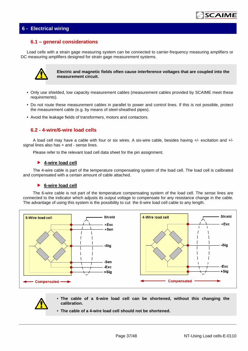
6.2 - 4-wire/6-wire load cells
A load cell may have a cable with four or six wires. A six-wire cable, besides having +/- excitation and +/- signal lines also has + and - sense lines.
Please refer to the relevant load cell data sheet for the pin assignment.
4-wire load cell
The 4-wire cable is part of the temperature compensating system of the load cell. The load cell is calibrated and compensated with a certain amount of cable attached.
6-wire load cell
The 6-wire cable is not part of the temperature compensating system of the load cell. The sense lines are connected to the indicator which adjusts its output voltage to compensate for any resistance change in the cable. The advantage of using this system is the possibility to cut the 6-wire load cell cable to any length.
• The cable of a 6-wire load cell can be shortened, w ithout this changing the calibration.
• The cable of a 4-wire load cell should not be short ened.

Page 38/48 NT-Using Load cells-E-0110
6.3 - Multiple load cells connection
In multiple load cell weighing systems, load cells can be wired in parallel by joining the load cell cable core ends of the same colour. For this, SCAIME provides ALCJB junction boxes. The output signal is then the average of the individual output signals.
Overloading of an individual load cell cannot then be detected from the output signal.
When multiple load cells are connected together in parallel the amount of current required to supply these load cells can exceed the maximum output of the indicator.
To calculate the required current output for a given installation, use the following formula:
LCLC
EXC NR
VcurrentRequired ××××
××××====1
VEXC: Excitation voltage RLC: Load cell input resistance NLC: Number of load cells
Check the load cell excitation rating of the indica tor to verify that it can supply the load cells
Sometimes it is necessary to trim the output of each individual load cell to avoid corner load differences, which are caused by:
• Difference in load cells output resistance. • unequal load distribution.
Trimming can be done by adjusting variable resistors (P1…Pn) placed into the excitation paths of the ALCJB.

Page 39/48 NT-Using Load cells-E-0110
6.4 - Cable extension
Extension cables must be shielded and of low capacitance. We recommend the use of SCAIME cables, which satisfy these requirements.
With cable extensions it is important to ensure a good connection with minimum contact resistance and good insulation.
When using the six-wire circuit, the effects of resistance changes in the extension cable are compensated.
If you extend the cable using the four-wire circuit, the sensitivity deviation can be eliminated by adjusting the amplifier. However, temperature effects can only be compensated when operating with the six-wire circuit.
6.5 - Grounding
Proper grounding and shielding can be critical to the successful application of load cells which are generating low level signals ( <5µV / scale division).
SCAIME load cell cables are provided with a braided shield which provides protection from electrostatic interference when properly used. This shield is generally floating ( not connected ) at the load cell avoiding the inadvertent creation of a "ground loop".
The load cell case and junction box are grounded by mechanical attachment to the structure to which they are mounted.
The braided shield enclosing the load cell leads is grounded at the indicator, which is grounded through the power cord or housing.
• load cell cables should be kept away from power cir cuits, with a minimum distance of 1m.
• Power supply cables should be crossed at right angl es.
Page 40/48 NT-Using Load cells-E-0110
7 - Load cells troubleshooting
Load cells might be damaged because of overloading (shocks), heavy electrical surges (lightning strikes), chemical or moisture ingress, mishandling (dropping, lifting on cable, etc.), vibration or internal component malfunction. As a direct result the scale or system might (zero) drift, provide unstable / unreliable readings or not register at all.
7.1 - In general
Carefully check the system integrity before evaluating the load cells:
• check for force shunts (might be caused by dirt, friction or mechanical misalignment).
• check cable connections to junction box and indicator.
Visually inspect the load cells before performing the tests as described on the following pages. Pay attention to signs of corrosion and the integrity of the cable.
The following test equipment is required to properly evaluate a load cell:
• A digital volt- and ohmmeter with a measuring accuracy of ±0.5Ω and ±0.1 mV, to measure the zero balance and integrity of the bridge circuit.
• A low voltage megohm meter, capable of reading 1000 MΩ at 50 volts, to measure the insulation resistance.
• A means to lift the dead load (weighbridge, tank, conveyor, etc.) to remove the load cell(s), i.e. an hydraulic jack, etc.
Load cells specifications can be found on the calibration sheet which is packed with each load cell.
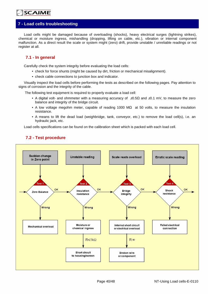
7.2 - Test procedure

Page 41/48 NT-Using Load cells-E-0110
7.2.1 - Test 1: Zero Balance
The Zero Balance is defined as the load cell signal in a "no-load" situation.
• Connect the load cell to a stable power supply (weighing indicator) with an excitation voltage of at least 5 volts. Disconnect any other load cell for multiple load cell systems.
• Measure the voltage across the load cell's signal leads with a voltmeter and divide this value by the input or excitation voltage to obtain the Zero Balance in mV/V.
• The measured value must be within the load cell zero balance limits.
Analysis
Changes in Zero Balance occur if the load cell has been permanently deformed by overloading or shocks.
Load cells that experience progressive zero output changes per time period are most likely undergoing a change in the strain gauge resistance because of moisture intrusion. However, in this case the insulation resistance and/or the bridge integrity will also be compromised.
7.2.2 - Test 2: Insulation resistance
The insulation resistance is measured between the load cell circuit and sensor body or cable shield.
• Disconnect the load cell from the junction box or indicator and connect all excitation, signal and sense (if applicable) leads together.
• Measure the insulation resistance with a low voltage megohmmeter between these four or six connected leads and the load cell body.
• Repeat the measurement between these leads and the cable shield.
• Finally measure the insulation resistance between the load cell body and cable shield.
Analysis
The insulation resistance should be 1000 MΩ. A lower value indicates electrical leakage, which is usually caused by moisture or chemical contaminations within the load cell or cable.
Extremely low values ( < 1kΩ ) indicate a short circuit rather than moisture ingress. Electrical leakage results usually in unstable load cell or scale reading output. The stability might vary with temperature.
• Some megohm meters supply 500V and could damage the load cell bridge circuitry.
• Do not excite the load cell with a voltage more tha n 50V.

Page 42/48 NT-Using Load cells-E-0110
7.2.3 - Test 3: Wheatstone bridge integrity
The bridge integrity is verified by measuring the input and output resistance as well as the bridge balance.
• Disconnect the load cell from the junction box or measuring device.
• Measure the input and output resistance with an ohmmeter across each pair of excitation and signal leads.
• Compare the input and output resistance with the data sheet.
• Measure and compare the resistance from -Sig to -Exc, and -Sig to +Exc to obtain the bridge balance. The difference between both values should be ≤1%.≤1%.≤1%.≤1%.
Analysis
Changes in bridge resistance or bridge balance are most often caused by a broken wire, an electrical component failure or internal short circuit.
This might result from over-voltage (lightning or welding), physical damage from shock, vibration, excessive temperature, or from production inconsistencies.
7.2.4 - Test 4: Shock resistance
• Connect the load cell to a stable power supply. Disconnect all other load cells for multiple load cell systems.
• Connect a voltmeter to the signal output leads.
• Lightly rap on the load cell support with a small mallet to mildly shock it. Exercise extreme care not to overload low capacity load cells while testing their shock resistance.
• Read the voltmeter during the test. The readings should not become erratic, should remain reasonably stable and return to original zero readings.
Analysis
Erratic readings may indicate a failed electrical connection or a damaged glue layer between strain gauge and load cell body as a result of an electrical transient.

Page 43/48 NT-Using Load cells-E-0110
8 - Annexes
A1 - DO’S & DONT’S of load cells
Do’s
REMEMBER, although load cells may look extremely rugged, they contain delicate sensing devices and can be very easily damaged by misuse rendering the unit unserviceable.
1. Select the right load cell for the application in terms of type and environmental compatibility.
2. Choose the right capacity.
3. Consider the required accuracy class.
4. Consider the environmental effects on accuracy (Wind, frictions, thermal expansions, attaching wiring or piping).
5. Design adequate over/under load protection as well as protection from other mechanical damage (e.g. physical abuse, rodent problems…).
6. Use dummy load cells prior to installation.
7. Beware of shock loadings. These can be very high and, although of short duration, can easily cause permanent damage.
8. Store and handle load cells carefully prior to and during installation.
9. Use high quality bolts with the recommended torque.
10. Check the surface to which a load cell is to be attached is flat and that the surface finish is correct.
11. Check cable colour code for load cell prior to connection.
12. Use good quality connecting terminals / Junction Boxes.
13. Inspect regularly load cells and weigh system especially after extreme weather conditions (electrical storms, flooding, seismic activity, etc.) and also before and after the seasons.
14. Check for corrosion damage to the load cell and mounting hardware.
Dont’s
1. Don't allow load cells to operate above their rated capacity.
2. Don’t allow a load cell to drop onto the floor.
3. Don’t hammer a load cell into place. Shock loads can permanently damage some units.
4. Don't use the load cell as a mechanical link.
5. Don't forget to protect the load cell cable.
6. Don't carry out electric welding near load cells.
7. Don't ever carry load cells by their cables.
8. Don't force bolts or other threaded assemblies.
9. Don't cut load cell cables unless necessary, performance may be effected.
10. Don't allow load cell to be the electrical link between ground and metal weigh structure. Envision the use of adequate bonding straps and isolators.
11. Don’t exceed the specified input voltage rating when energizing a load cell.
12. Don’t exceed operating temperature range.
13. Don't allow build up of water/debris around load cell.

Page 44/48 NT-Using Load cells-E-0110
A2 - Ingress protection under EN60529
0
No protection
1
Protected against solid objects up to 50mm and accidental touch by hand
2
Protected against solid objects up to 12mm and accidental touch by fingers
3
Protected against solid objects up to 2,5mm and accidental touch by tools
4
Protected against solid objects up to 1mm and accidental touch by tools and small wires
5
Protected against dust. The dust entrance should not interfere with operation
6
Complete protection against dust
0
No protection
1
Protected against vertically falling drops of water
2
Protected against direct sprays of water up to 15° from the vertical
3
Protected against direct sprays of water up to 60° from the vertical
4
Protected against direct sprays of water up to 60° from the vertical
5
Protected against low pressure jets of water from all directions
6
Protection against strong jets of water from all directions
7
Protection against the effects of immersion between 15cm to 1m
8
Protection against long periods of immersion at a specified depth .
A3 - Ingress protection under DIN40050
IP69K test according to DIN 40050 / part 9
• cycle of 30 seconds • 14 - 16 litres per minute • water 80°C
The goal of the test is to simulate pressure cleaning conditions. In the test fixture, the load cell is exposed to a water jet of 100 bar at a temperature of 80 °C. The duration of each cle aning cycle is 30s. The test is performed with a spray nozzle located at defined angles and at a distance of 10 - 15 cm from the load cell.
The high protection rating guarantees absolute ingress-resistance, even in applications subject to frequent cleaning processes, e.g. in the food industry.
IP 1st number
Protection against solid objects
IP 2nd number
Protection against liquids

Page 45/48 NT-Using Load cells-E-0110
A4 – Safety instructions
In cases where a breakage may cause injury to persons or damage to equipment, the user must take appropriate safety measures (such as fall protection, overload protection, etc.). Safe and trouble-free operation of the load cells requires proper transportation, correct storage, assembly and mounting as well as careful operation and maintenance.
It is essential to comply with the relevant accident prevention regulations. In particular you should take into account the limit loads quoted in the specifications.
Use in accordance with the regulations
SCAIME load cells have been designed for weighing applications. Use for any additional purpose shall be deemed to be not in accordance with the regulations.
To ensure safe operation, the load cells should only be used as described in this manual. It is also essential to observe the appropriate legal and safety regulations for the application concerned during use. The same applies to the use of accessories.
Load cells can be used as machine components (e.g. with tank weighing). Please note in these cases that, in order to provide a high sensitivity, the load cells have not been designed with the safety factors normally applied in machine design.
The load cell is not a safety element within the me aning of its use in accordance with the regulations.
Qualified staff
These load cells are only to be installed by qualified personnel strictly in accordance with the specifications and with the safety rules and regulations which follow. It is also essential to observe the appropriate legal and safety regulations for the application concerned. The same applies to the use of accessories.
Qualified personnel means persons entrusted with the installation, fitting, commissioning and operation of the product who possess the appropriate qualifications for their function.
Environmental conditions
In the context of your application, please note that acids and all materials which release (chlorine) ions will attack all grades of stainless steel and their welding seams. This may result in corrosion which can lead to the failure of the load cell.
Prohibition of own modifications
The load cells must not be modified from the design or safety engineering point of view except with our express agreement. Any modification shall exclude all liability on our part for any damage resulting therefrom.
Option: Explosion proof version
Users must comply with all relevant erection regulations during installation.
The installation conditions listed in the certificate of conformity and/or type examination certificate must be complied with.

Page 46/48 NT-Using Load cells-E-0110
Notes

Page 47/48 NT-Using Load cells-E-0110
Notes

Page 48/48 NT-Using Load cells-E-0110
Weighing technology
SCAIME SAS ZI de Juvigny, BP501 74105 Annemasse – France Tel. (+33) 4 50 87 78 64 Fax. (+33) 4 50 87 78 46 [email protected] www.scaime.com
SC
AIM
E S
AS
. All rights reserved. Inform
ation is subject to change without notice.
You can download our documents on
WWW.SCAIME.COM
Using load cells