deploying network foundation services - cisco.com · borderless campus 1.0 design guide 2 deploying...
TRANSCRIPT

C H A P T E R 2
Deploying Network Foundation ServicesAfter designing each tier in the model, the next step in enterprise network design is to establish key network foundation technologies. Regardless of the applications and requirements that enterprises demand, the network must be designed to provide a consistent user experience independent of the geographical location of the user or application. The following network foundation design principles or services must be deployed in each campus location to provide resiliency and availability so all users can access and use enterprise applications:
• Implementing campus network infrastructure
• Network addressing hierarchy
• Network foundation technologies for campus designs
• Multicast for applications delivery
• QoS for application performance optimization
• High availability to ensure business continuity in the event of a network failure
Design guidance for each of these six network foundation technologies is discussed in the following sections, including where they are deployed in each tier of the campus design model, the campus location, and capacity.
Implementing Campus Network InfrastructureChapter 1, “Borderless Campus Design and Deployment Models,” provided various design options for deploying the Cisco Catalyst and Cisco Nexus 7000 platforms in a multi-tier, centralized large campus and remote medium and small campus locations. The Borderless Enterprise Reference network is designed to build simplified network topologies for easier operation, management, and troubleshooting independent of campus location. Depending on network size, scalability, and reliability requirements, the Borderless Enterprise Reference design applies a common set of Cisco Catalyst and Nexus 7000 platforms in different campus network layers as described in Chapter 1, “Borderless Campus Design and Deployment Models.”
The foundation of the enterprise campus network must be based on Cisco recommendations and best practices to build a robust, reliable, and scalable infrastructure. This subsection focuses on the initial hardware and software configuration of a wide-range of campus systems to build hierarchical network designs. The recommended deployment guidelines are platform- and operational mode-specific. The initial recommended configurations should be deployed on the following Cisco platforms independent of their roles and the campus tier in which they are deployed. Implementation and deployment guidelines for advanced network services are explained in subsequent sections:
• Cisco Catalyst 6500-E in VSS mode
2-1Borderless Campus 1.0 Design Guide

Chapter 2 Deploying Network Foundation ServicesImplementing Campus Network Infrastructure
• Cisco Nexus 7000
• Cisco Catalyst 4500E
• Cisco Catalyst 3750-X Stackwise Plus
• Cisco Catalyst 3750-X 3560-X in standalone mode
Deploying Cisco Catalyst 6500-E in VSS ModeAll the VSS design principles and foundational technologies defined in this subsection remain consistent when the Cisco Catalyst 6500-E is deployed in VSS mode at the campus core or the distribution layer.
Prior to enabling the Cisco Catalyst 6500-E in VSS mode, the enterprise network administrator should adhere to Cisco recommended best practices to take complete advantage of the virtualized system and minimize the network operation downtime when migrating in a production network. Migrating VSS from the standalone Catalyst 6500-E system requires multiple pre- and post-migration steps to deploy the virtual system that includes building the virtual system itself and migrating the existing standalone network configuration to operate in the virtual system environment. Refer to the following document for the step-by-step migration procedure: http://www.cisco.com/en/US/products/ps9336/products_tech_note09186a0080a7c74c.shtml
The following subsections provide guidance on the procedures and mandatory steps required when implementing VSS and its components in the campus distribution and core:
• VSS High-Availability
• VSS Identifiers
• Virtual Switch Link
• VSL Design Consideration
• Unified Control-Plane
• VSL Dual-Active Detection and Recovery
• VSL Dual-Active Management
• VSS Quad-Sup Migration
VSS High-Availability
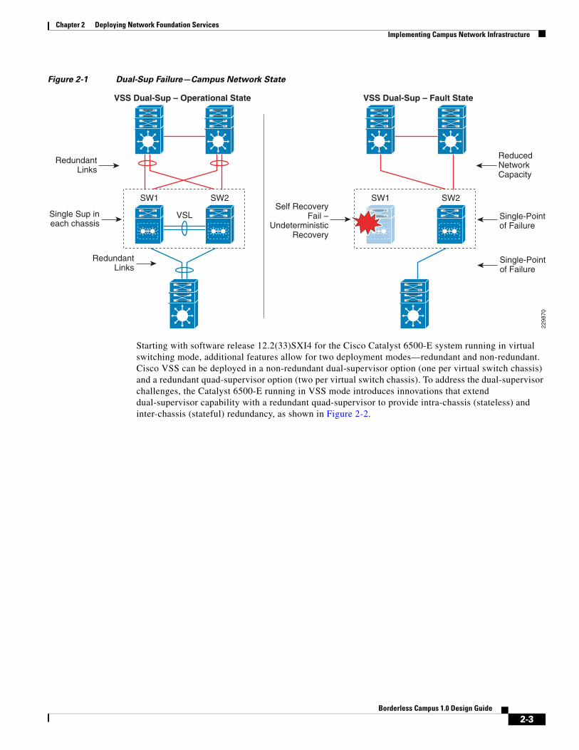
The Cisco Catalyst 6500-E simplifies the control and management plane by clustering two systems deployed in the same role and running them in the same campus layers. Along with multiple innovations to build a unified system with a distributed forwarding design, Cisco VSS technology also leverages the existing single chassis-based NSF/SSO redundancy infrastructure to develop an inter-chassis redundancy solution. Hence it allows for a redundant two-supervisor model option which is distributed between two clustered chassis, instead of a single-standalone redundant chassis. While the dual-sup design solved the original challenge of simplifying network topology and managing multiple systems, in the early phase it was not designed to provide supervisor redundancy within each virtual switch chassis. Hence, the entire virtual switch chassis gets reset during supervisor failure or may remain down if it cannot bootup at all due to faulty hardware or software. In either case, during the fault state the campus network faces several challenges, as illustrated in Figure 2-1.
2-2Borderless Campus 1.0 Design Guide
Chapter 2 Deploying Network Foundation ServicesImplementing Campus Network Infrastructure
Figure 2-1 Dual-Sup Failure—Campus Network State
Starting with software release 12.2(33)SXI4 for the Cisco Catalyst 6500-E system running in virtual switching mode, additional features allow for two deployment modes—redundant and non-redundant. Cisco VSS can be deployed in a non-redundant dual-supervisor option (one per virtual switch chassis) and a redundant quad-supervisor option (two per virtual switch chassis). To address the dual-supervisor challenges, the Catalyst 6500-E running in VSS mode introduces innovations that extend dual-supervisor capability with a redundant quad-supervisor to provide intra-chassis (stateless) and inter-chassis (stateful) redundancy, as shown in Figure 2-2.
SW1
RedundantLinks
SW2
VSL
2298
70
VSS Dual-Sup – Operational State VSS Dual-Sup – Fault State
SW1 SW2
ReducedNetworkCapacity
Single-Pointof Failure
Single-Pointof Failure
Single Sup ineach chassis
Self RecoveryFail –
UndeterministicRecovery
RedundantLinks
2-3Borderless Campus 1.0 Design Guide

Chapter 2 Deploying Network Foundation ServicesImplementing Campus Network Infrastructure
Figure 2-2 Quad-Sup Failure—Campus Network Recovered State
When designing the network with the Catalyst 6500-E in VSS mode, Cisco recommends deploying VSS in quad-supervisor mode, which helps build a more resilient and mission critical campus foundation network. Deploying VSS in quad-supervisor mode offers the following benefits over the dual-supervisor design:
• Maintains inter-chassis redundancy and all other dual-supervisor benefits
• Increases virtual switch intra-chassis redundancy
• Offers deterministic network recovery and availability during abnormal supervisor failure
• Maintains in-chassis network services module availability
• Minimize single point link or system failure conditions during a fault state
• Protects overall network capacity and reliability
VSS Identifiers
This is the first pre-migration step to be implemented on two standalone Cisco Catalyst 6500-Es in the same campus tier that are planned to be clustered into a single logical entity. Cisco VSS defines the following two types of physical node identifiers to distinguish a remote node within the logical entity, as well as to set the logical VSS domain identity to uniquely identify beyond the single VSS domain boundary.
SW1 SW2
VSL
SW1
RedundantLinks
SW2
VSL
2298
71
VSS Quad-Sup – Operational State VSS Quad-Sup – Self-Recovered State
Recovered Network Capacity
Redundant Virtual-System,Sup and VSL
Recovered Network Capacity
DualRedundanctSup in each
chassis
Self Recovery
Fail
NewActive
Supervisor
RedundantLinks
2-4Borderless Campus 1.0 Design Guide

Chapter 2 Deploying Network Foundation ServicesImplementing Campus Network Infrastructure
Domain ID
Defining the domain identifier (ID) is the initial step in creating a VSS with two physical chassis. The domain ID value ranges from 1 to 255. The Virtual Switch Domain (VSD) comprises two physical switches and they must be configured with a common domain ID. When implementing VSS in a multi-tier campus network design, the unique domain ID between different VSS pairs prevents network protocol conflicts and allows for simplified network operation, troubleshooting, and management.
Switch ID
Each VSD supports up to two physical switches to build a single logical virtual switch. The switch ID value is 1 or 2. Within VSD, each physical chassis must have a uniquely-configured switch ID to successfully deploy VSS. From a control plane and management plane perspective, when the two physical chassis are clustered after VSS migration, it creates a single large system. Therefore all distributed physical interfaces between the two chassis are automatically appended with the switch ID (i.e., <switch-id>/<slot#>/<port#>) or TenGigabitEthernet 1/1/1. The significance of the switch ID remains within VSD; all the interface IDs are associated to the switch IDs and are retained independent of control plane ownership. See Figure 2-3.
Figure 2-3 VSS Domain and Switch ID
The following sample configuration shows how to configure the VSS domain ID and switch ID:
Standalone Switch 1:
VSS-SW1(config)# switch virtual domain 20VSS-SW1(config-vs-domain)# switch 1
Standalone Switch 2:
VSS-SW2(config)# switch virtual domain 20VSS-SW2(config-vs-domain)# switch 2
Domain 20
Domain 10
SW1 SW2
2298
72
Distribution
Core
Access
VSL
SW1 SW2VSL
2-5Borderless Campus 1.0 Design Guide

Chapter 2 Deploying Network Foundation ServicesImplementing Campus Network Infrastructure
Switch Priority
When the two switches boot, switch priority is negotiated to determine control plane ownership for the virtual switch. The virtual switch configured with the higher priority takes control plane ownership, while the lower priority switch boots up in redundant mode. The default switch priority is 100; the lower switch ID is used as a tie-breaker when both virtual switch nodes are deployed with the default settings.
Cisco recommends deploying both virtual switch nodes with identical hardware and software to take full advantage of the distributed forwarding architecture with a centralized control and management plane. Control plane operation is identical on each of the virtual switch nodes. Modifying the default switch priority is an optional setting since each of the virtual switch nodes can provide transparent operation to the network and the user.
Virtual Switch Link
To cluster two physical chassis into single a logical entity, Cisco VSS technology enables the extension of various types of single-chassis internal system components to the multi-chassis level. Each virtual switch must be deployed with direct physical links, which extend the backplane communication boundary (these are known as Virtual-Switch Links (VSL)).
VSL can be considered Layer 1 physical links between two virtual switch nodes and are designed to operate without network control protocols. Therefore, VSL links cannot establish network protocol adjacencies and are excluded when building the network topology tables. With customized traffic engineering on VSL, it is tailored to carry the following major traffic categories:
• Inter-switch control traffic
– Inter-Chassis Ethernet Out Band Channel (EOBC) traffic— Serial Communication Protocol (SCP), IPC, and ICC
– Virtual Switch Link Protocol (VSLP) —LMP and RRP control link packets
• Network control traffic
– Layer 2 protocols —STP BPDU, PagP+, LACP, CDP, UDLD, LLDP, 802.1x, DTP, etc.
– Layer 3 protocols—ICMP, EIGRP, OSPF, BGP, MPLS LDP, PIM, IGMP, BFD, etc.
• Data traffic
– End user data application traffic in single-home network designs
– An integrated service module with centralized forwarding architecture (i.e., FWSM)
– Remote SPAN
Using EtherChannel technology, the VSS software design provides the flexibility to increase on-demand VSL bandwidth capacity and to protect network stability during VSL link failure or malfunction.
The following sample configuration shows how to configure VSL EtherChannel:
Standalone Switch 1:
VSS-SW1(config)# interface Port-Channel 1VSS-SW1(config-if)#description SW1-VSL-EtherChannelVSS-SW1(config-if)# switch virtual link 1
VSS-SW1(config)# interface range Ten 1/1 , Ten 5/4 - 5 , Ten 6/4 -5VSS-SW1(config-if)#description SW1-VSL-Dual-Sup-Uplink+6708VSS-SW1(config-if)# channel-group 1 mode on
Standalone Switch 2:
2-6Borderless Campus 1.0 Design Guide

Chapter 2 Deploying Network Foundation ServicesImplementing Campus Network Infrastructure
VSS-SW2(config)# interface Port-Channel 2VSS-SW1(config-if)#description SW2-VSL-EtherChannelVSS-SW2(config-if)# switch virtual link 2
VSS-SW2(config)# interface range Ten 1/1 , Ten 5/4 - 5 , Ten 6/4 -5VSS-SW1(config-if)#description SW2-VSL-Dual-Sup-Uplink+6708VSS-SW2(config-if)# channel-group 2 mode on
VSL Design Consideration
Implementing VSL EtherChannel is a simple task, however it requires a properly optimized design to achieve high reliability and availability. Deploying VSL requires careful planning to keep system virtualization intact during VSS system component failure on either virtual switch node. Reliable VSL design requires planning in three categories:
• VSL Links Diversification
• VSL Bandwidth Capacity
• VSL QoS
VSL Links Diversification
Complete VSL link failure may break system virtualization and create network instability. Designing VSL link redundancy by using diverse physical paths on both systems prevents network instability, eliminates single point-of-failure conditions, and optimizes the bootup process.
VSL is not supported on all Catalyst 6500-E linecards due to the special VSL encapsulation headers that are required within the VSL protocols. The next-generation specialized Catalyst 6500-E 10G-based supervisor and linecard modules are fully capable and equipped with modern hardware ASICs to support VSL communication. VSL EtherChannel can bundle 10G member links with any of following next-generation hardware modules:
• Sup720-10G
• WS-X6708
• WS-X6716-10G and WS-X6716-10T (must be deployed in performance mode to enable VSL capability)
When VSS is deployed in dual-sup and quad-sup designs, Cisco recommends a different VSL design to maintain network stability. In a dual-sup VSS configuration, Figure 2-4 shows an example of how to build VSL EtherChannel with multiple diverse physical fiber paths using the supervisor 10G uplink ports and VSL-capable 10G hardware modules.
Figure 2-4 Recommended Dual-Sup VSL Links Design
Deploying VSL with multiple, diversified VSL ink designs offers the following benefits:
• Leverage non-blocking 10G ports from supervisor modules.
• Use 10G ports from VSL-capable WS-X6708 or WS-X6716 linecard module to protect against abnormal failures on the supervisor uplink port (e.g., GBIC failure).
• Reduces single point-of-failure probabilities as it is rare to trigger multiple hardware faults on diversified cables, GBIC, and hardware modules.
SW2
Ten5/4
Ten1/1
Ten5/4
Ten1/16708/6716
Sup720-10GE
SW1
6708/6716
Sup720-10GE VSL
2289
56
2-7Borderless Campus 1.0 Design Guide

Chapter 2 Deploying Network Foundation ServicesImplementing Campus Network Infrastructure
• A VSL-enabled 10G module boots up more rapidly than other installed modules in the system. The software is designed to initialize VSL protocols and communication early in the bootup process. If the same 10G module is shared to connect other network devices, then depending on the network module type and slot bootup order, it is possible to minimize traffic loss during the system initialization process.
• Use a four-class, built-in QoS model on each VSL member link to optimize inter-chassis communication traffic, network control, and user data traffic.
Since VSS quad-sup increases chassis redundancy, network architects must redesign VSL to maintain its reliability and capacity during individual supervisor module failures. Figure 2-5 shows two different approaches to building VSL EtherChannel with multiple diverse and full-mesh fiber paths between all four supervisor modules in the VSS domain. Both designs are recommended to increase VSL reliability, capacity, and diversity during multiple abnormal faults conditions. When migrating from a dual-sup VSS design (Figure 2-4) to a quad-sup VSS design, VSL re-design is necessary, as illustrated in Figure 2-5.
Figure 2-5 Recommended Quad-Sup VSL Links Design
Deploying a diverse and full-mesh VSL in a VSS quad-sup design offers the following benefits:
• Both quad-sup VSL designs leverage all of the key advantage of a dual-sup VSS design.
• Both designs use the non-blocking 10G uplink ports from all four supervisors to build full-mesh VSL connection.
• VSS quad-sup design option # 1 offers the following benefits:
– A cost-effective solution to leverage all four supervisor modules to build well-diversified VSL paths between both chassis. It provides the flexibility to continue to use a non-VSL capable linecard module for other network functions.
– Increases the overall bandwidth capacity to enable more hardware-integrated borderless network and application services at the campus aggregation layer.
– Maintains up to 20G VSL bandwidth for traffic redirection during individual supervisor module failure.
– Increases network reliability by minimizing the probability of dual-active or split-brain conditions that de-stabilize the VSS domain and the network.
• VSS quad-sup design option # 2 offers following benefits:
– The primary difference between option 1 and 2 is option #2 introduces additional 10G ports from VSL-capable WS-X6708, WS-X6716-10G, or WS-X6716-10T linecard modules.
– This design option provides additional VSL link redundancy and bandwidth protection against abnormal failure that prevents redundant supervisor modules in both virtual switch chassis from booting.
– Accelerates VSL-enabled 10G module bootup time, which allows for rapid build up of network adjacencies and forwarding information.
Sup720-10GESup720-10GE
Sup720-10GESup720-10GE
5/45/56/56/4
5/45/56/56/4
2298
73
VSL
SW1 SW2
Quad-Sup VSL Design -1
Sup720-10GESup720-10GE
Sup720-10GESup720-10GE
5/45/56/56/4
5/45/56/56/4
1/1 1/1VSL
SW1 SW2
Quad-Sup VSL Design - 2
6708/67166708/6716
2-8Borderless Campus 1.0 Design Guide

Chapter 2 Deploying Network Foundation ServicesImplementing Campus Network Infrastructure
– Based on EtherChannel load sharing rules, this design may not provide optimal network data load sharing across all five VSL links. However, this VSL design is highly suited to protect VSS system reliability during multiple supervisor fault conditions.
VSL Bandwidth Capacity
From each virtual switch node, VSL EtherChannel can bundle up to eight physical member links. Therefore, VSL can be bundled up to 80G of bandwidth capacity; the exact capacity depends on the following factors:
• The aggregated network uplink bandwidth capacity on per virtual switch node basis, e.g., 2 x 10GE diversified to the same remote peer system.
• Designing the network with single-homed devices connectivity (no MEC) forces at least half of the downstream traffic to flow over the VSL link. This type of connectivity is highly discouraged.
• Remote SPAN from one switch member to other. The SPANed traffic is considered as a single flow, hence the traffic hashes only over a single VSL link that can lead to oversubscription of a particular link. The only way to improve traffic distribution is to have an additional VSL link. Adding a link increases the chance of distributing the normal traffic that was hashed on the same link carrying the SPAN traffic, which may then be sent over a different link.
• If the VSS is carrying the borderless services hardware (such as FWSM, WiSM, etc.), then depending on the service module forwarding design, it may be carried over the VSL bundle. Capacity planning for each of the supported services blades is beyond the scope of this design guide.
For optimal traffic load sharing between VSL member-links, it is recommended to bundle VSL member links in powers of 2 (i.e., 2, 4, and 8).
VSL QoS
The service and application demands of next-generation enterprise networks require a strong, resilient, and highly-available network with on-demand bandwidth allocation for critical services without compromising performance. Cisco VSS in dual- and quad-sup designs are designed with application intelligence and automatically enable QoS on the VSL interface to provide bandwidth and resource allocation for different class-of-service traffic.
The QoS implementation on VSL EtherChannel operates in restricted mode as it carries critical inter-chassis backplane traffic. Independent of global QoS settings, the VSL member links are automatically configured with system-generated QoS settings to protect different class of applications. To retain system stability, the inter-switch VSLP protocols and QoS settings are fine tuned to protect high priority traffic with different thresholds, even during VSL link congestion.
To deploy VSL in non-blocking mode and increase the queue depth, the Sup720-10G uplink ports can be configured in one of the following two QoS modes:
• Non-10G-only mode (Default)—In this mode, all supervisor uplink ports must follow a single queuing mode. Each 1G/10G supervisor uplink port operates with a default queue structure (1p3q4T). If any 10-Gbps uplink port is used for the VSL link, the remaining ports (10 Gbps or 1Gbps) follow the same CoS mode of queuing for any other non-VSL connectivity because VSL only allows CoS-based queuing. This default VSL QoS structure is designed to automatically protect critical inter-switch communication traffic to maintain virtual system reliability and to preserve original QoS settings in data packets for consistent QoS treatment as a regular network port. The default mode also provides the flexibility to utilize all 1G supervisor uplink ports for other network applications (e.g., out-of-band network management).
2-9Borderless Campus 1.0 Design Guide
Chapter 2 Deploying Network Foundation ServicesImplementing Campus Network Infrastructure
• 10G-only mode—In this mode, the 10G supervisor uplink ports can double the egress queue structure from 1p3q4t to 1p7q4t. To increase the number egress queues on 10G uplink port from a shared hardware ASIC, this mode requires all 1G supervisors uplink ports to be administratively disabled. Implementing this mode does not modify the default CoS-based trust (ingress classification), queueing (egress classification) mode, or the mapping table.
The 10G-only QoS mode can increase the number of egress queue counts but cannot provide the additional advantage to utilize all queue structures since it maintains all other QoS settings the same as default mode; hence it is recommended to retain the VSL QoS in default mode.
Unified Control-Plane
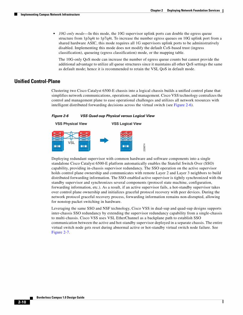
Clustering two Cisco Catalyst 6500-E chassis into a logical chassis builds a unified control plane that simplifies network communications, operations, and management. Cisco VSS technology centralizes the control and management plane to ease operational challenges and utilizes all network resources with intelligent distributed forwarding decisions across the virtual switch (see Figure 2-6).
Figure 2-6 VSS Quad-sup Physical versus Logical View
Deploying redundant supervisor with common hardware and software components into a single standalone Cisco Catalyst 6500-E platform automatically enables the Stateful Switch Over (SSO) capability, providing in-chassis supervisor redundancy. The SSO operation on the active supervisor holds control plane ownership and communicates with remote Layer 2 and Layer 3 neighbors to build distributed forwarding information. The SSO-enabled active supervisor is tightly synchronized with the standby supervisor and synchronizes several components (protocol state machine, configuration, forwarding information, etc.). As a result, if an active supervisor fails, a hot-standby supervisor takes over control plane ownership and initializes graceful protocol recovery with peer devices. During the network protocol graceful recovery process, forwarding information remains non-disrupted, allowing for nonstop packet switching in hardware.
Leveraging the same SSO and NSF technology, Cisco VSS in dual-sup and quad-sup designs supports inter-chassis SSO redundancy by extending the supervisor redundancy capability from a single-chassis to multi-chassis. Cisco VSS uses VSL EtherChannel as a backplane path to establish SSO communication between the active and hot-standby supervisor deployed in a separate chassis. The entire virtual switch node gets reset during abnormal active or hot-standby virtual switch node failure. See Figure 2-7.
2298
74
VSS Physical View VSS Logical View
VSL
2-10Borderless Campus 1.0 Design Guide

Chapter 2 Deploying Network Foundation ServicesImplementing Campus Network Infrastructure
Figure 2-7 Inter-Chassis SSO Operation in VSS—Dual-Sup and Quad-Sup
To successfully establish SSO communication between two virtual switch nodes, the following criteria must match between both virtual switch nodes:
• Identical software versions
• Consistent VSD and VSL interface configurations
• Power mode and VSL-enabled module power settings
• Global PFC Mode
• SSO and NSF-enabled
During the bootup process, SSO synchronization checks all of the above criteria with the remote virtual system. If any of the criteria fail to match, it forces the virtual switch chassis to boot in an RPR or cold-standby state that cannot synchronize the protocol and forwarding information with the current SSO ACTIVE virtual switch chassis.
While inter-chassis SSO redundancy provides network simplification and stability, it cannot provide chassis-level redundancy when a supervisor in either of the virtual switches fails and cannot self-recover. Cisco VSS with quad-sup retains the orginal inter-chassis design as the dual-sup design, however it addresses intra-chassis dual-sup redundancy challenges. To support quad-sup redundant capability, the software infrastructure requires changes to simplify the roles and responsibilities to manage the virtual switch with a distributed function. Figure 2-8 illustrates two supervisor modules in each virtual switch chassis to increase redundancy, enable distributed control and forwarding planes, and intelligently utilize all possible resources from quad-sups.
StandbyVirtualSwitch
ActiveVirtualSwitch
VSLCFC or DFC Line Cards
CFC or DFC Line Cards
2289
57
SF: Switch FabricRP: Route ProcessorPFC: Policy Forwarding Card
CFC: Centralized Forwarding CardDFC: Distributed Forwarding Card
Active Supervisor
RPSF PFC
CFC or DFC Line Cards
CFC or DFC Line Cards
CFC or DFC Line Cards
CFC or DFC Line Cards
CFC or DFC Line Cards
CFC or DFC Line Cards
Standby HOT Supervisor
SF PFCRP
CFC or DFC Line Cards
CFC or DFC Line Cards
CFC or DFC Line Cards
CFC or DFC Line Cards
Switch-1 Switch-2
2-11Borderless Campus 1.0 Design Guide

Chapter 2 Deploying Network Foundation ServicesImplementing Campus Network Infrastructure
Figure 2-8 VSS Quad-Sup Redundancy
The quad-sup VSS design divides the role and ownership between two clustered virtual switching systems and allows the in-chassis redundant supervisors to operate transparently and seamlessly of SSO communication:
• SSO ACTIVE—The supervisor module that owns the control and management plane. It establishes network adjacencies with peer devices and develops distributes forwarding information across the virtual switching system.
• SSO HOT_STANDBY—The supervisor module in HOT_STANDBY mode that synchronizes several system components, state machines, and configurations in real-time to provide graceful and seamless recovery during SSO ACTIVE failure.
• In-Chassis ACTIVE (ICA)—The in-chassis active supervisor module within the virtual switch chassis. The ICA supervisor module could be in the SSO ACTIVE or HOT_STANDBY role. The ICA module communicates with and controls all modules deployed in the local chassis.
• In-Chassis STANDBY (ICS)—The in-chassis standby supervisor module within the virtual switch chassis. The ICS supervisor module communicates with the local ICA supervisor module to complete its WARM bootup procedure and keeps system components in synchronization to take over ICA ownership if the local ICA fails and cannot recover.
The Cisco Catalyst 6500-E running in VSS quad-sup mode introduces Route-Processor Redundancy-WARM (RPR-WARM) to provide intra-chassis redundancy. Cisco’s new RPR-WARM supervisor redundancy technology is a platform-dependent innovation that enables co-existence of multiple supervisor redundant modes in a virtual switch. Only a compatible ICS supervisor module may bootup in RPR-WARM mode. The term RPR-WARM combines following hybrid functions on ICS supervisor modules:
• Supervisor—RPR-WARM extends the capability of legacy RPR cold-state redundancy technology and synchronizes certain system configurations such as the startup-configuration, VLAN database, and BOOT variable. The in-chassis standby supervisor does not synchronize any hardware or software state machines to provide graceful recovery during local ICA module failure. Refer to Chapter 4, “Deploying High Availability in Campus,” for more details.
• Distributed linecard—RPR-WARM enables a unique function on the ICS supervisor module. During the bootup process ICS supervisor initializes as the regular supervisor, but gets WARM upgraded with the new Sup720-LC IOS software, which allows the ICS supervisor to operate as a distributed
In-Chassis ActiveSupervisor
In-Chassis StandbySupervisor
SSO – ActiveVirtual Switch
In-Chassis ActiveSupervisor
In-Chassis StandbySupervisor
SSO – HOT_STANDBYVirtual Switch
VSL
CFC or DFC Line Cards
CFC or DFC Line Cards
2298
75
SF: Switch FabricRP: Route ProcessorPFC: Policy Feature Card
CFC: Centralized Forwarding CardDFC: Distributed Forwarding Card
Active Supervisor
RPSF PFC
Standby Supervisor
RPSF PFC
CFC or DFC Line Cards
CFC or DFC Line Cards
CFC or DFC Line Cards
CFC or DFC Line Cards
Standby HOT Supervisor
SF PFCRP
CFC or DFC Line Cards
CFC or DFC Line Cards
Switch-1 Switch-2
Standby Supervisor
RPSF PFC
2-12Borderless Campus 1.0 Design Guide

Chapter 2 Deploying Network Foundation ServicesImplementing Campus Network Infrastructure
linecard. The Sup720-LC IOS software is packaged within the 12.2(33)SXI4 IOS software release. When the ICS module is operating in distributed linecard and RPR-WARM mode, it enables all its physical ports for network communication and is synchronized with hardware information for distributed forwarding.
VSL Dual-Active Detection and Recovery
The preceding section described VSL EtherChannel functions as an extended backplane link that enables system virtualization by transporting inter-chassis control traffic, network control plane, and user data traffic. The state machine of the unified control plane protocols and distributed forwarding entries gets dynamically synchronized between the two virtual switch nodes. Any fault triggered on a VSL component leads to a catastrophic instability in the VSS domain and beyond. The virtual switch member that assumes the role of hot-standby maintains constant communication with the active switch. The role of the hot-standby switch is to assume the active role as soon as it detects a loss of communication with its peer via all VSL links without the operational state information of the remote active peer node. Such an unstable network condition is known as dual-active, where both virtual switches get split with a common set of configurations and each individually takes control plane ownership to communicate with neighboring devices. The network protocols detect inconsistency and instability when VSS peering devices detect two split systems claiming the same addressing and identification. Figure 2-9 depicts the state of a campus topology in a single active-state and a dual-active state.
Figure 2-9 Single Active and Dual-Active Campus Topology
System virtualization is affected during the dual-active network state and splits the single virtual system into two identical Layer 2/Layer3 systems. This condition can destabilize campus network communication, with two split system advertising duplicate information. To prevent such network instability, Cisco VSS introduces the following two methods to rapidly detect dual-active conditions and recover by isolating the old active virtual switch from network operation before the network becomes destabilized:
• Direct detection method—This method requires an extra physical connection between both virtual switch nodes. Dual-Active Fast-Hello (Fast-Hello) and Bidirectional Forwarding Decision (BFD) protocols are specifically designed to detect the dual-active condition and prevent network malfunction. All VSS-supported Ethernet media and modules can be used to deploy this method. For additional redundancy, VSS allows the configuration of up to four dual-active fast-hello links between virtual switch nodes. Cisco recommends deploying Fast-Hello in lieu of BFD for the following reasons:
SW1
Active Hot_Standby
SW2
2289
58
SW1
Active Active
SW2
Single Active Network State Dual-Active Network State
2-13Borderless Campus 1.0 Design Guide

Chapter 2 Deploying Network Foundation ServicesImplementing Campus Network Infrastructure
– Fast-Hello can rapidly detect a dual-active condition and trigger the recovery procedure. Independent of routing protocols and network topology, Fast-Hello offers faster network recovery.
– Fast-Hello enables the ability to implement dual-active detection in a multi-vendor campus or data center network environment.
– Fast-Hello optimizes the protocol communication procedure without reserving higher system CPU and link overheads.
– Fast-Hello supersedes a BFD-based detection mechanism.
– Fast-Hello links do not carry network control or user data traffic, so they can be enabled on regular Gigabit-Ethernet links.
• Indirect detection method—This method relies on an intermediate trusted Layer2/Layer3 MEC Cisco Catalyst remote platform to detect the failure and notify the old-active switch about the dual-active detection. Cisco extended the capability of the PAgP protocol with extra TLVs to signal the dual-active condition and initiate the recovery procedure. Most Cisco Catalyst switching platforms can be used as a trusted PAgP+ partner to deploy the indirect detection method.
All dual-active detection protocols and methods can be implemented in parallel. As depicted in Figure 2-10, in a VSS network deployment peering with Cisco Catalyst platforms, Cisco recommends deploying Fast-Hello and PAgP+ methods for rapid detection to minimize network topology instability and to retain application performance. In a dual-sup VSS design, Fast-Hello can be implemented between supervisor or linecard ports. Fast-hello and PAgP+ detection methods do not operate differently on VSS quad-sup. However to ensure Fast-Hello links are available during supervisor failures and minimize the number of Fast-Hello ports used, it is recommended to deploy Fast-Hello on the linecard modules instead of the supervisor.
Figure 2-10 Recommended Dual-Active Detection Method
The following sample configuration illustrates the implementation of both methods:
• Dual-Active Fast-Hello
cr23-VSS-Core(config)#interface range Gig1/7/1 , Gig2/7/1cr23-VSS-Core(config-if-range)# dual-active fast-hello
! Following logs confirms fast-hello adjacency is established on ! both virtual-switch nodes.
SW1 SW2VSL
VSS Client
2298
76
VSS Dual-Sup –Dual-Active Detection
Dual -Active TrustedePAgP MEC
1/5/12/5/1
Fast-Hello
SW1 SW2VSL
VSS Client
VSS Quad-Sup –Dual-Active Detection
Dual -Active TrustedePAgP MEC
1/7/12/7/1
Fast-Hello
2-14Borderless Campus 1.0 Design Guide

Chapter 2 Deploying Network Foundation ServicesImplementing Campus Network Infrastructure
%VSDA-SW1_SP-5-LINK_UP: Interface Gi1/7/1 is now dual-active detection capable%VSDA-SW2_SPSTBY-5-LINK_UP: Interface Gi2/7/1 is now dual-active detection capable
cr23-VSS-Core#show switch virtual dual-active fast-helloFast-hello dual-active detection enabled: YesFast-hello dual-active interfaces:Port Local StatePeer Port Remote State-----------------------------------------------------------------------------Gi1/7/1 Link up Gi2/7/1 Link up
• PAgP+
Enabling or disabling dual-active trusted mode on Layer 2/Layer 3 MEC requires MEC to be in an administrative shutdown state. Prior to implementing trust settings, network administrators should plan for downtime to provision PAgP+-based dual-active configuration settings:
cr23-VSS-Core(config)#int range Port-Channel 101 - 102cr23-VSS-Core(config-if-range)#shutdown
cr23-VSS-Core(config)#switch virtual domain 20cr23-VSS-Core(config-vs-domain)#dual-active detection pagp trust channel-group 101 cr23-VSS-Core(config-vs-domain)#dual-active detection pagp trust channel-group 102
cr23-VSS-Core(config)#int range Port-Channel 101 - 102 cr23-VSS-Core(config-if-range)#no shutdown
cr23-VSS-Core#show switch virtual dual-active pagp PAgP dual-active detection enabled: YesPAgP dual-active version: 1.1
Channel group 101 dual-active detect capability w/nbrsDual-Active trusted group: Yes Dual-Active Partner Partner PartnerPort Detect Capable Name Port VersionTe1/1/2 Yes cr22-6500-LB Te2/1/2 1.1Te1/3/2 Yes cr22-6500-LB Te2/1/4 1.1Te2/1/2 Yes cr22-6500-LB Te1/1/2 1.1Te2/3/2 Yes cr22-6500-LB Te1/1/4 1.1
Channel group 102 dual-active detect capability w/nbrsDual-Active trusted group: Yes Dual-Active Partner Partner PartnerPort Detect Capable Name Port VersionTe1/1/3 Yes cr24-4507e-MB Te4/2 1.1Te1/3/3 Yes cr24-4507e-MB Te3/1 1.1Te2/1/3 Yes cr24-4507e-MB Te4/1 1.1Te2/3/3 Yes cr24-4507e-MB Te3/2 1.1
VSL Dual-Active Management
Managing the VSS system during a dual-active condition becomes challenging when two individual systems in the same network tier contain a common network configuration. Network instability can be prevented with the dual-active detection mechanism; the old ACTIVE virtual-switch chassis disables all physical and logical interfaces. By default this recovery mechanic blocks in-band management access to the system to troubleshoot and analyze the root cause of dual-active. The network administrator should
2-15Borderless Campus 1.0 Design Guide

Chapter 2 Deploying Network Foundation ServicesImplementing Campus Network Infrastructure
explicitly configure VSS to exclude disabling the network management interface during the dual-active recovery state. Any Layer 3 physical management ports can be configured to be excluded; since dual-active breaks system virtualization, logical interfaces like SVIs and Port-Channels cannot be excluded. To minimize network instability, it is highly recommended to exclude only network management ports from both virtual-switch chassis. The following is a sample configuration to exclude the Layer 3 network management ports of both virtual-switch chassis:
Dist-VSS(config)#switch virtual domain 1Dist-VSS(config-vs-domain)#dual-active exclude interface Gi1/5/2Dist-VSS(config-vs-domain)#dual-active exclude interface Gi2/5/2
Dist-VSS#show switch virtual dual-active summaryPagp dual-active detection enabled: YesBfd dual-active detection enabled: YesFast-hello dual-active detection enabled: Yes
Interfaces excluded from shutdown in recovery mode: Gi1/5/2 Gi2/5/2In dual-active recovery mode: No
VSS Quad-Sup Migration
As in new deployments, migrating from a dual-sup to a quad-sup VSS design is simplified and can be performed without network downtime. The existing dual-sup VSS systems must be migrated to quad-sup-capable IOS software on the ICA and ICS modules to deploy quad-sup.
Note ICS supervisor modules must not be inserted into virtual switching until the ICA supervisor is deployed with VSS quad-sup software capability. Inserting the ICS supervisor module prior to upgrading the software is not supported and may create adverse effects on the system and network.
Figure 2-11 VSS Quad-Sup Migration Procedure
Cisco recommends the following migration guidelines to gracefully deploy quad-sup:
Step 1 Upgrade Cisco IOS software on the ICA supervisor module to 12.2(33)SXI4 and later releases. This upgrade procedure must leverage Enhanced Fast Software Upgrade (eFSU) technology to gracefully upgrade both virtual switch chassis. Verify that the network is stable and fully operational. eFSU is supported starting with 12.2(33)SXI3 and later releases. For more details, refer to Catalyst 6500-E VSS eFSU Software Design and Upgrade Process in Chapter 4, “Deploying High Availability in Campus.”
Step 2 Physically insert the ICS supervisor module; it must bootup with the same Cisco IOS software as the ICA module. The ICS supervisor module must meet the following criteria when deploying VSS in quad-sup mode:
• Identical supervisor module types
• ICA and ICS are running identical 12.2(33)SXI4 and later releases software and license versions.
2298
77
Software upgrade using eFSU
Install Redundant Supervisors
Redesign VSL
2-16Borderless Campus 1.0 Design Guide

Chapter 2 Deploying Network Foundation ServicesImplementing Campus Network Infrastructure
The ICS supervisor role and current status on both virtual switch chassis can be verified upon completing a successful bootup process:
cr23-VSS-Core#show switch virtual redundancy | inc Switch|Current Software
My Switch Id = 1Peer Switch Id = 2
Switch 1 Slot 5 Processor Information :Current Software state = ACTIVE
Switch 1 Slot 6 Processor Information :Current Software state = RPR-Warm
Switch 2 Slot 5 Processor Information :Current Software state = STANDBY HOT (switchover target)
Switch 2 Slot 6 Processor Information :Current Software state = RPR-Warm
Step 3 Pre-configure full-mesh VSL connections between the ICA and ICS modules and bundle into existing VSL EtherChannel, as illustrated in Figure 2-5. Connect new VSL fiber links fibers and make sure they are in an operational state. Finally move the VSL cable when required to build full-mesh VSL connections.
Deploying VSS Quad-Sup with Mismatch IOS Version
The intra-chassis ICA/ICS role negotiation procedure and parameters are different than the SSO role negotiation that occurs between ICA on two virtual switch chassis. During the bootup process, the ICA and ICS go through several intra-chassis negotiation processes— role, software compatibility check, etc. If any of the criteria fail to match with ICA, then the ICA forces ICS to fallback in (ROMMON) mode.
Deploying quad-sup with mismatched IOS versions between ICA and ICS becomes challenging when installation is done remotely or the VSS system is not easily accessible to install compatible IOS software on local storage of the ICS supervisor module. In such cases, Cisco IOS software provides the flexibility to disable version mismatch check and allow ICS to bootup with a different IOS version than ICA. However ICS must boot with the Cisco IOS software that includes quad-sup capability—12.2(33)SXI4 and later releases.
The network administrator must execute following step prior to inserting the ICS supervisor to mitigate IOS mismatch challenge between ICA and ICS module:
Step 1 Disable IOS software mismatch version check from global configuration mode:
cr23-VSS-Core(config)#no switch virtual in-chassis standby bootup mismatch-check
Step 2 Physically insert the ICS supervisor module in virtual switches SW1 and SW2. During intra-chassis role negotiation, ICA will report the following message, however it will allow ICS to complete the bootup process in RPR-WARM mode:
%SPLC_DNLD-SW1_SP-6-VS_SPLC_IMAGE_VERSION_MISMATCH: In-chassis Standby in switch 1 is trying to boot with a different image version than the In-chassis Active
cr23-VSS-Core#show module switch 1 | inc Supervisor 5 5 Supervisor Engine 720 10GE (Active) VS-S720-10G SAD120407CT 6 5 Supervisor Engine 720 10GE (RPR-Warm) VS-S720-10G SAD120407CL
2-17Borderless Campus 1.0 Design Guide

Chapter 2 Deploying Network Foundation ServicesImplementing Campus Network Infrastructure
Step 3 Copy the ICA-compatible IOS software version on the local storage of the SW1 and SW2 ICS supervisor modules:
cr23-VSS-Core#copy <image_src_path> sw1-slot6-disk0:<image>cr23-VSS-Core#copy <image_src_path> sw2-slot6-disk0:<image>
Step 4 Re-enable IOS software mismatch version check from global configuration mode. Cisco recommends to keep version check enabled; running mismatched IOS versions between ICA and ICS may cause SSO communication to fail during the next switchover process, which will result in the virtual switch entering RPR mode and keeping the entire chassis in a non-operational state.
cr23-VSS-Core(config)#switch virtual in-chassis standby bootup mismatch-check
Step 5 Force ICS supervisor module reset. In the next bootup process, the ICS module will now bootup with an ICA-compatible IOS software version:
cr23-VSS-Core#hw-module switch 1 ics resetProceed with reset of Sup720-LC? [confirm] Y
cr23-VSS-Core#hw-module switch 2 ics resetProceed with reset of Sup720-LC? [confirm] Y
Table 2-1 summarizes the ICS operational state during bootup process in each virtual switch chassis with compatible and incompatible Cisco IOS software versions.
Virtual Routed MAC
The MAC address allocation for the interfaces does not change during a switchover event when the hot-standby switch takes over as the active switch. This avoids gratuitous ARP updates (MAC address changed for the same IP address) from devices connected to VSS. However, if both chassis are rebooted at the same time and the order of the active switch changes (the old hot-standby switch comes up first and becomes active), then the entire VSS domain uses that switch’s MAC address pool. This means that the interface inherits a new MAC address, which triggers gratuitous ARP updates to all Layer 2 and Layer 3 interfaces. Any networking device connected one hop away from the VSS (and any networking device that does not support gratuitous ARP) will experience traffic disruption until the MAC address of
Table 2-1 VSS Quad-sup Software Compatibility Matrix and ICS State
SW1-ICA – IOS(SSO-ACTIVE) SW1-ICS – IOS
SW2-ICA – IOS(SSO-STANDBY) SW2-ICS – IOS
SW1 ICS StateSW2 ICS State
12.2(33)SXI4 12.2(33)SXI4 12.2(33)SXI4 12.2(33)SXI4 SW1 ICS – RPR-WARM
SW2 ICS – RPR-WARM
12.2(33)SXI4 12.2(33)SXI4a 12.2(33)SXI4 12.2(33)SXI4a
SW1 ICS – ROMMON1
SW2 ICS – ROMMON1
1. Software version compatibility check can be disabled to allow ICS to bootup with mismatch versions.
12.2(33)SXI4 12.2(33)SXI4a 12.2(33)SXI4 12.2(33)SXI4 SW1 ICS – ROMMON1
SW2 ICS – RPR-WARM
12.2(33)SXI4 PRE
12.2(33)SXI4
12.2(33)SXI4 PRE
12.2(33)SXI4
SW1 ICS – ROMMON2
SW2 ICS – ROMMON2
2. Disabling Software version compatibility check is ineffective in this case as ICS is attempting to bootup with IOS software that does not support VSS Quad-sup capability.
2-18Borderless Campus 1.0 Design Guide

Chapter 2 Deploying Network Foundation ServicesImplementing Campus Network Infrastructure
the default gateway/interface is refreshed or timed out. To avoid such a disruption, Cisco recommends using the configuration option provided with the VSS in which the MAC address for Layer 2 and Layer 3 interfaces is derived from the reserved pool. This takes advantage of the virtual switch domain identifier to form the MAC address. The MAC addresses of the VSS domain remain consistent with the usage of virtual MAC addresses, regardless of the boot order.
The following configuration illustrates how to configure the virtual routed MAC address for the Layer 3 interface under switch-virtual configuration mode:
cr23-VSS-Core(config)#switch virtual domain 20cr23-VSS-Core(config-vs-domain)#mac-address use-virtual
Deploying Cisco Nexus 7000The campus core can be deployed in an alternative standalone network design to a virtualized campus core with Cisco VSS technology. In the large and medium enterprise campus network, architects may need a solution with a high-performance network backbone to handle data traffic at wire-speed and future proof the backbone to scale the network for high density. Cisco recommends deploying the Cisco Nexus 7000 system in the campus core, as its robust system architecture is specifically designed to deliver high-performance networking in large-scale campus and data center network environments. With advanced hardware, lossless switching architecture, and key foundational software technology support, the Cisco Nexus 7000 is equipped to seamlessly integrate in the enterprise campus core layer. The Nexus 7000 is designed to operate using the next-generation unified Cisco NX-OS operating system that combines advanced technology and software architectural benefits from multiple operating systems. Cisco NX-OS can interoperate in a heterogeneous vendor campus network using industry-standard network protocols.
2-19Borderless Campus 1.0 Design Guide

Chapter 2 Deploying Network Foundation ServicesImplementing Campus Network Infrastructure
Figure 2-12 Cisco Nexus 7000-based Campus Core design
The campus core layer baseline requirement to build a high-speed, scalable, and resilient core remains intact when deploying the Cisco Nexus 7000. It is highly recommended to deploy redundant system components to maintain optimal backbone switching capacity and network availability for non-stop business communication. This subsection provides guidelines and recommendations for initial system setup with the following redundant components:
• Implementing Redundant Supervisor Module
• Distributed Forwarding with Crossbar Fabric Module
• Deploying Layer 3 Network I/O Module
Implementing Redundant Supervisor Module
The supervisor module maintains the centralized network control and management plane of the Nexus 7000 system. The robust architecture of the Sup-1 module is uniquely designed with multiple components and decouples the control, management, and data plane operation. All Layer 3 routing functions are handled centrally by the supervisor module to communicate with peering devices and build the dynamic routing and forwarding (FIB) table. The supervisor dynamically synchronizes FIB to the forwarding engine on every I/O for distributed forwarding to optimize switching performance. To optimize the performance, scalability, and reliability of the Nexus 7000 system, it is critical to understand its internal architecture and the function of each of its components. This section provides a brief explanation of some of the key supervisor internal components:
2905
71
Distribution
Access
Core
Data Center/Services Block/Edge
Nexus 7000
Data Center
QFP
PSTNWAN
Redundant/High-SpeedStandalone Core System
High-Density 10GbpsCampus Backbone
Hitless CoreSwitching
2-20Borderless Campus 1.0 Design Guide

Chapter 2 Deploying Network Foundation ServicesImplementing Campus Network Infrastructure
• CPU—The network control plane processing is handled by the dual-core CPU that offers flexibility to scale control plane capacity in a large campus network environment. To maintain control plane redundancy, the Nexus 7000 system must be deployed in a redundant supervisor network configuration. The system configuration, network protocols, and internal state machines are constantly synchronized between the active and standby supervisor modules.
• CMP—Connectivity Management Processor (CMP) is a dedicated “light-weight” CPU running independent of the operating system on the active and standby supervisor modules for out-of-band management and monitoring capability during system disaster recovery.
• Central Arbiter—A special ASIC to control the crossbar switch fabric with intelligence to access data communication between I/O modules. By combining the central arbitration function on the supervisor with distributed Virtual Output Queue (VOQ) on distributed I/O modules, it offers multiple benefits:
– The central arbiter ensures that the distributed traffic switched through the switch backplane gets fair fabric access and bandwidth on egress from the I/O module (e.g., multiple ingress interfaces sending traffic to a single upstream network interface or I/O module).
– Intelligently protects and prioritizes the high-priority data or control plane traffic switched through the system fabric.
– VOQ is a hardware buffer pool that represents the bandwidth on an egress network module. The central arbiter grants fabric access to the ingress I/O module if bandwidth on the egress module is available. This software design minimzes network congestion and optimizes fabric bandwidth usage.
– Provides 1+1 redundancy and hitless switching architecture with active/active central arbitration on active and standby supervisor modules.
Deploying redundant supervisor modules is a base system requirement to provide non-stop business communication during any hardware or software abnormalities. With graceful protocol capability and lossless switching architecture, the Nexus 7000-based campus core can be hitless during soft switchover of the active supervisor module. The Cisco Nexus 7000 supports NSF/SSO for Layer 3 protocols to provide supervisor redundancy; the active supervisor module synchronizes the NSF-capable protocol state machines to the standby supervisor to take over ownership during switchover. The I/O modules remain in a full operational state and continue to switch network data traffic with distributed FIB, while the new supervisor gracefully recovers protocol adjacencies with neighbor devices. Figure 2-13 summarizes the distributed system components and redundant plane architecture in the Cisco Nexus 7000 system.
2-21Borderless Campus 1.0 Design Guide

Chapter 2 Deploying Network Foundation ServicesImplementing Campus Network Infrastructure
Figure 2-13 Cisco Nexus 7000 Supervisor Redundancy Architecture
The Nexus 7000 system by default gets configured in HA or SSO configuration mode by adding a redundant supervisor module. Even the Layer 3 protocol is by default in NSF-capable mode and does not require the network administrator to manually configure NSF capability in a redundant system.
cr35-N7K-Core1#show system redundancy statusRedundancy mode--------------- administrative: HA operational: HA
This supervisor (sup-1)----------------------- Redundancy state: Active Supervisor state: Active Internal state: Active with HA standby
Other supervisor (sup-2)------------------------ Redundancy state: Standby Supervisor state: HA standby Internal state: HA standby
Distributed Forwarding with Crossbar Fabric Module
As described earlier, Cisco Nexus 7000 is a fully-distributed system that decouples the control and data plane functions between different modular components. While the supervisor module handles control processing centrally and I/O modules perform distributed forwarding, the Nexus 7000 system has a multi-stage and modular crossbar switch fabric architecture. The crossbar fabric module enables multi-terabit backplane switching capacity between high-speed I/O modules through a dedicated fabric channel interface. For high fabric bandwidth capacity and fabric module redundancy, up to five crossbar fabric modules can be deployed in a single Nexus 7000 system. It is imperative to understand the internal crossbar fabric module function in order to design the Nexus 7000 system in the campus core for better core network switching capacity and resiliency.
2905
72CPU: Central Processing Unit CA: Central Arbiter CMP: Connectivity Management Processing VOQ: Virtual Output Queue
Cisco Nexus 7000
Active Supervisor
CAVOQCPU CMP
Standby Supervisor
CAVOQCPU CMP
I/O ModuleVOQI/O Module VOQ
Fabric
Fabric AccessRedundancy
SSORedundancy
Central ArbitrationRedundancy
SupervisorRedundancy
2-22Borderless Campus 1.0 Design Guide

Chapter 2 Deploying Network Foundation ServicesImplementing Campus Network Infrastructure
Fabric Bandwidth Access
As described earlier, the fabric ASIC and VOQ on each distributed I/O module request fabric access from the central arbiter located on the supervisor. If the destination or egress module has sufficient bandwidth, the request gets granted and the data can be sent to the fabric module. If the ingress and egress ports are located on the same I/O module, then the central arbitration process does not get involved. This internal crossbar switching architecture provides multiple benefits as described in the previous section.
Fabric Module Bandwidth Capacity
With the parallel fabric switching architecture, each I/O module can achieve up to 46 Gbps of bi-directional backplane capacity from each individual fabric module. To access the fabric bandwidth between I/O modules, the supervisor continues to provide central arbitration to optimally and intelligently utilize all fabric switching capacity. Deploying additional fabric modules can increase the aggregated fabric switching capacity and fabric redundancy on the Nexus 7000 system. For wire-speed per-port performance, the 10G I/O module supports up to 80 Gbps per slot. Hence to gain complete 10Gbps I/O module capacity, it is recommended to deploy at least two fabric modules in the system.
Fabric Module Load Balancing
The I/O module builds two internal uni-directional parallel switching paths with each crossbar fabric module. With the multi-stage fabric architecture, the ingress module determines the fabric channel and module to select prior to forwarding data to the backplane. The Nexus 7000 system is optimized to intelligently load share traffic across all available crossbar fabric modules. The unicast data traffic gets load balanced in round-robin style across each active fabric channel interface and multicast traffic leverages a hash algorithm to determine a path to send traffic to the fabric module. This internal load share design helps optimize fabric bandwidth utilization and increase redundancy.
Figure 2-14 Nexus 7000 Crossbar Fabric Module Architecture
Fabric Module Redundancy
Maintaining Nexus 7000 backplane switching capacity is as important as core layer network switching capacity. With all network paths in an operational state, the 80Gbps per slot I/O module may not operate at full switching capacity due to a lack of available internal switch fabric bandwidth during fabric
2905
73
Cisco Nexus 7000
Fabric Load Balancing
: 46Gbps Bandwidth Per Fabric Module
: 80Gbps Bandwidth Per 10Gbps I/O Module
Active Supervisor
Standby Supervisor
Fab ASIC
10Gbps I/O Module Fab ASIC
Fab ASIC10Gbps I/O Module
92Gbps Fabric Capacity withdual Crossbar Fabric Module tosupport 10Gbps I/O module
N+1 Fabric Redundancy
Fabric Module-1
Fabric Module-2
Fabric Module-3
2-23Borderless Campus 1.0 Design Guide
Chapter 2 Deploying Network Foundation ServicesImplementing Campus Network Infrastructure
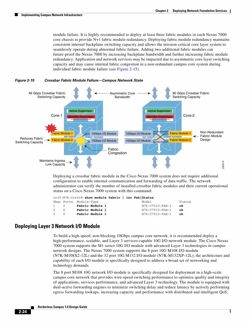
module failure. It is highly recommended to deploy at least three fabric modules in each Nexus 7000 core chassis to provide N+1 fabric module redundancy. Deploying fabric module redundancy maintains consistent internal backplane switching capacity and allows the mission-critical core layer system to seamlessly operate during abnormal fabric failure. Adding two additional fabric modules can future-proof the Nexus 7000 by increasing backplane bandwidth and further increasing fabric module redundancy. Application and network services may be impacted due to asymmetric core layer switching capacity and may cause internal fabric congestion in a non-redundant campus core system during individual fabric module failure (see Figure 2-15).
Figure 2-15 Crossbar Fabric Module Failure—Campus Network State
Deploying a crossbar fabric module in the Cisco Nexus 7000 system does not require additional configuration to enable internal communication and forwarding of data traffic. The network administrator can verify the number of installed crossbar fabric modules and their current operational status on a Cisco Nexus 7000 system with this command:
cr35-N7K-Core1# show module fabric | inc Fab|StatusXbar Ports Module-Type Model Status1 0 Fabric Module 1 N7K-C7010-FAB-1 ok2 0 Fabric Module 1 N7K-C7010-FAB-1 ok3 0 Fabric Module 1 N7K-C7010-FAB-1 ok
Deploying Layer 3 Network I/O Module
To build a high-speed, non-blocking 10Gbps campus core network, it is recommended deploy a high-performance, scalable, and Layer 3 services-capable 10G I/O network module. The Cisco Nexus 7000 system supports the M1 series 10G I/O module with advanced Layer 3 technologies in campus network designs. The Nexus 7000 system supports the 8 port 10G M108 I/O module (N7K-M108X2-12L) and the 32 port 10G M132 I/O module (N7K-M132XP-12L); the architecture and capability of each I/O module is specifically designed to address a broad set of networking and technology demands.
The 8 port M108 10G network I/O module is specifically designed for deployment in a high-scale campus core network that provides wire-speed switching performance to optimize quality and integrity of applications, services performance, and advanced Layer 3 technology. The module is equipped with dual-active forwarding engines to minimize switching delay and reduce latency by actively performing egress forwarding lookups, increasing capacity and performance with distributed and intelligent QoS,
2905
74
Core-1 Core-2
FabricCongestion
Active Supervisor
Standby Supervisor
Reduces FabricSwitching Capacity
Non-RedundantFabric\ ModuleDesign
Asymmetric CoreBandwidth
Maintains IngressLink Capacity
46 Gbps Crossbar FabricSwitching Capacity
80 Gbps Crossbar FabricSwitching Capacity
Active Supervisor
Standby Supervisor
10Gbps I/O Module
10Gbps I/O Module
Fabric Module-1
Fabric Module-2
10Gbps I/O Module
10Gbps I/O Module
Fabric Module-1
Fabric Module-2
2-24Borderless Campus 1.0 Design Guide

Chapter 2 Deploying Network Foundation ServicesImplementing Campus Network Infrastructure
ACL, etc. The 32 port 10G M132 module is designed for deployment in a high-density, high-performance aggregation layer to connect a large number of access switches. The backplane capacity of the M132 is the same as the M108, however with increased port density it operates at a 4:1 oversubscription rate that may not be an ideal hardware design for a high-speed campus backbone network. Hence it is recommended to deploy the M108 I/O module in the Cisco Nexus 7000 system in the campus core layer.
The active supervisor module establishes the protocol adjacencies with neighbors to build the unicast routing information base (URIB) or multicast routing information base (MRIB). The software-generated routing information remains operational on the supervisor module. To provide hardware-based forwarding, each I/O network module builds local distributed forwarding information tables. The distributed FIB table on the I/O module is used for local destination address and path lookup to forward data with new egress information without involving the supervisor module in the forwarding decision. The central arbitration and crossbar fabric data switching is involved when the egress port is on a different I/O network module. The network data traffic can be “local-switch” if the ingress and egress path is within the same module based on local FIB information. If the Nexus 7000 core system is deployed with multiple M108 I/O modules, then designing the ingress and egress physical paths may help optimize performance and increase network redundancy.
Figure 2-16 Cisco Nexus 7000 Distributed I/O Forwarding Architecture
The I/O network module is plug-n-play like the crossbar fabric module and does not require any specific user provisioning to enable internal system communication. The operational status of the module can be verified using the same syntax:
cr35-N7K-Core1# show module | inc Gbps1 8 10 Gbps Ethernet XL Module N7K-M108X2-12L ok2 8 10 Gbps Ethernet XL Module N7K-M108X2-12L ok
2905
75
Cisco Nexus 7000
Module-2
Eth1/1Eth1/1
Eth1/3Eth1/2 Eth1/3Eth1/2
Module-1 Fabric
Distributed ForwardingSynchronization
: Unicast Routing Information Base
: Unicast/Multicast Forwarding Information Base
URIB
MRIB : Multicast Routing Information Base
: Cross Module Ingress/Egress Traffic
: Same Module Local Switch Ingress/Egress Traffic
Active Supervisor
Standby Supervisor
URIB MRIB
FIB/MFIB
VOQ FE
FE : Forwarding Engine
I/O Module VOQFE
FIB/MFIBFIB/MFIB
I/O Module
2-25Borderless Campus 1.0 Design Guide

Chapter 2 Deploying Network Foundation ServicesImplementing Campus Network Infrastructure
Deploying Cisco Catalyst 4500EIn the Borderless Campus design, the Cisco Catalyst 4500E Series platform can be deployed in different roles. In large campus networks, the Catalyst 4500E must be deployed in a high-density access layer that requires wire-speed network services with enterprise-class network reliability for constant business operation during abnormal faults. In medium campus networks, the Catalyst 4500E series platform can be considered as an alternative aggregation layer system to the Catalyst 6500. The Catalyst 4500E can also be deployed in a collapsed distribution/core role for a small, space-constrained campus location. The next-generation Cisco Catalyst 4500E Series switch is a multi-slot, modular, highly-scalable, multi-gigabit, high-speed, and resilient platform. A single Catalyst 4500E Series platform in an enterprise design is built with redundant hardware components to be consistent with the Catalyst 6500-E VSS-based design. For Catalyst 4500E in-chassis supervisor redundancy, network administrators must consider Catalyst 4507R+E or 4510R+E slot chassis to accommodate redundant supervisors and use LAN network modules for core and edge network connectivity.
The Cisco Catalyst 4500E Series supports a wide-range of supervisor modules designed for high-performance Layer 2 and Layer 3 network connectivity. This reference design recommends deploying the next-generation Sup7-E to support borderless services in the campus access and distribution layers. The flexible and scalable architecture of the next-generation Sup7-E supervisor is designed to enable multiple innovations in the campus access and distribution layers for borderless services. The Catalyst 4500E with Sup7-E supervisor module is ideal for large enterprise networks that have dense wiring closets with a large number of end points that require power (PoE), constant network availability, wire-rate throughput, and low-latency switching performance for time-sensitive applications such as high-definition video conferencing. The Sup7-E operates on a new IOS software infrastructure and is designed to offer multiple hardware-assisted advanced technology benefits without compromising system performance.
Alternatively, the current-generation Sup6-E and Sup6L-E can also be deployed as they support hardware switching capabilities, scalability, and performance for various types of applications and services deployed in the campus network.
Implementing Redundant Supervisor
The Cisco Catalyst 4507R+E and 4510R+E models support intra-chassis or single-chassis supervisor redundancy with dual-supervisor support. Implementing a single Catalyst 4507R+E in highly-resilient mode at various campus layer with multiple redundant hardware components protects against different types of abnormal failures. This reference design guide recommends deploying redundant Sup7-E, Sup6-E, or Sup6L-E supervisor modules to deploy full high-availability feature parity. Therefore, implementing intra-chassis supervisor redundancy and initial network infrastructure setup will be simplified for small campus networks. Figure 2-17 illustrates the Cisco Catalyst 4500E-based intra-chassis SSO and NSF capability.
2-26Borderless Campus 1.0 Design Guide

Chapter 2 Deploying Network Foundation ServicesImplementing Campus Network Infrastructure
Figure 2-17 Intra-Chassis SSO Operation
During the bootup process, SSO synchronization checks various criteria to ensure both supervisors can provide consistent and transparent network services during failure events. If any of the criteria fail to match, it forces the standby supervisor to boot in RPR or a cold-standby state in which it cannot synchronize protocol and forwarding information from the active supervisor. The following sample configuration illustrates how to implement SSO mode on Catalyst 4507R+E and 4510R+E chassis deployed with Sup7-E, Sup6-E, and Sup6L-E redundant supervisors:
cr24-4507e-MB#config tcr24-4507e-MB (config)#redundancycr24-4507e-MB (config-red)#mode sso
cr24-4507e-MB#show redundancy statesmy state = 13 - ACTIVE peer state = 8 - STANDBY HOT
< snippet >
Deploying Supervisor Uplinks
Every supported supervisor module in the Catalyst 4500E supports different uplink port configurations for core network connectivity. The next-generation Sup7-E supervisor module offers unparalleled performance and bandwidth for the premium-class campus access layer. Each Sup7-E supervisor module can support up to four 1G or 10G non-blocking, wire-rate uplink connections to build high-speed distribution-access blocks. The current-generation Sup6-E and Sup6L-E supervisor modules support up two 10G uplinks or can be deployed as four different 1G uplinks using Twin-Gigabit converters. To build a high-speed, low-latency campus backbone network, it is recommended to leverage and deploy 10G uplinks to accommodate bandwidth-hungry network services and applications operating in the network.
All Cisco Catalyst 4500E Series supervisors are designed with unique architectures to provide constant network availability and reliability during supervisor resets. Even during supervisor soft-switchover or administrative reset events, the state machines of all deployed uplinks remain operational and with the centralized forwarding architecture they continue to switch packets without impacting any time-sensitive applications like high-definition video conferencing. This unique architecture protects bandwidth capacity while administrators perform supervisor IOS software upgrades or an abnormal event in software triggers a supervisor reset. Cisco recommends building diversified, distributed, and redundant uplink network paths as such designs offer the following benefits:
2298
78CPU: Control-Plane ProcessingFPGA: Hardware Based Forwarding Information
PP: Packet ProcessorFE: Forwarding Engine
Stub Linecards
RedundantSup7-E/Sup6-E/
Sup6L-E
Line Card
FEPP FPGACPU
Cisco Catalyst 4507R+E/4510R+E
Standby Supervisor
Active Supervisor
FEPP FPGACPU
Line Card
Line Card
Line Card
Line Card
2-27Borderless Campus 1.0 Design Guide
Chapter 2 Deploying Network Foundation ServicesImplementing Campus Network Infrastructure
• Improve application performance by increasing aggregated network capacity with multiple high-speed 10Gbps uplinks in the access-distribution block.
• Enhance bi-directional traffic engineering with intelligent network data load sharing across all uplink physical ports.
• Improve system and application performance by utilizing the distributed architecture advantage of hardware resources—buffers, queue, TCAM, etc.
• Protect network-level redundancy and minimize congestion between distributed aggregation systems caused during a major outage at the access or distribution layer.
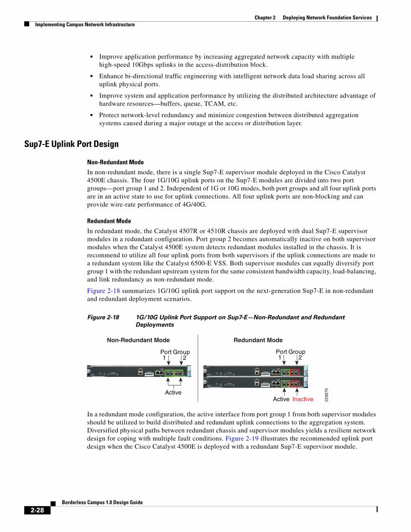
Sup7-E Uplink Port Design
Non-Redundant Mode
In non-redundant mode, there is a single Sup7-E supervisor module deployed in the Cisco Catalyst 4500E chassis. The four 1G/10G uplink ports on the Sup7-E modules are divided into two port groups—port group 1 and 2. Independent of 1G or 10G modes, both port groups and all four uplink ports are in an active state to use for uplink connections. All four uplink ports are non-blocking and can provide wire-rate performance of 4G/40G.
Redundant Mode
In redundant mode, the Catalyst 4507R or 4510R chassis are deployed with dual Sup7-E supervisor modules in a redundant configuration. Port group 2 becomes automatically inactive on both supervisor modules when the Catalyst 4500E system detects redundant modules installed in the chassis. It is recommend to utilize all four uplink ports from both supervisors if the uplink connections are made to a redundant system like the Catalyst 6500-E VSS. Both supervisor modules can equally diversify port group 1 with the redundant upstream system for the same consistent bandwidth capacity, load-balancing, and link redundancy as non-redundant mode.
Figure 2-18 summarizes 1G/10G uplink port support on the next-generation Sup7-E in non-redundant and redundant deployment scenarios.
Figure 2-18 1G/10G Uplink Port Support on Sup7-E—Non-Redundant and Redundant
Deployments
In a redundant mode configuration, the active interface from port group 1 from both supervisor modules should be utilized to build distributed and redundant uplink connections to the aggregation system. Diversified physical paths between redundant chassis and supervisor modules yields a resilient network design for coping with multiple fault conditions. Figure 2-19 illustrates the recommended uplink port design when the Cisco Catalyst 4500E is deployed with a redundant Sup7-E supervisor module.
2298
79Active
Port Group21
Redundant ModeNon-Redundant Mode
Port Group21
Active Inactive
2-28Borderless Campus 1.0 Design Guide

Chapter 2 Deploying Network Foundation ServicesImplementing Campus Network Infrastructure
Figure 2-19 Recommended 4500E Redundant-Sup Uplink Network Design
Sup6-E Uplink Port Design
Non-Redundant Mode
In non-redundant mode, there is a single supervisor module deployed in the Catalyst 4500E chassis. In non-redundant mode, by default both uplink physical ports can be deployed in 10G or 1G with Twin-Gigabit converters. Each port operates in a non-blocking state and can switch traffic at wire-rate performance.
Redundant Mode
In the recommended redundant mode, the Catalyst 4500E chassis is deployed with dual supervisors. To provide wire-rate switching performance, by default port group 1 in both the active and hot-standby supervisors is in active mode and port group 2 is placed in an in-active state. The default configuration can be modified by changing the Catalyst 4500E backplane settings to sharing mode. Shared backplane mode enables the operation of port group 2 on both supervisors. Note that sharing the 10G backplane ASIC between the two 10G ports does not increase switching capacity; rather it creates 2:1 oversubscription. If the upstream device is deployed with chassis redundancy (i.e., Catalyst 6500-E VSS), then it is highly recommended to deploy all four uplink ports for the following reasons:
• Helps develop full-mesh or V-shape physical network topology from each supervisor module.
• Increases high availability in the network during an individual link, supervisor, or other hardware component failure event.
• Reduces latency and network congestion when rerouting traffic through a non-optimal path.
Figure 2-20 summarizes uplink port support on the Sup6-E module in non-redundant and redundant deployment scenarios.
2905
76
SW1 SW2VSL
Catalyst 4500E – Sup7E
Sup-2 Uplink PortsSup-1 Uplink Ports
2-29Borderless Campus 1.0 Design Guide

Chapter 2 Deploying Network Foundation ServicesImplementing Campus Network Infrastructure
Figure 2-20 Catalyst 4500E Sup6-E Uplink Mode
The next-generation supervisor Catalyst 4500E Sup7-E must be considered for aggregated wire-rate 40G performance. The following sample configuration provides instructions for modifying the default backplane settings on the Catalyst 4500E platform deployed with Sup6-E supervisors in redundant mode. The new backplane settings will be effective only after the chassis is reset; therefore, it is important to plan the downtime during this implementation:
cr24-4507e-MB#config tcr24-4507e-MB(config)#hw-module uplink mode shared-backplane
!A 'redundancy reload shelf' or power-cycle of chassis is required ! to apply the new configuration
cr24-4507e-MB#show hw-module uplink Active uplink mode configuration is Shared-backplane
cr24-4507e-MB#show hw-module mod 3 port-group Module Port-group ActiveInactive---------------------------------------------------------------------- 3 1 Te3/1-2Gi3/3-6
cr24-4507e-MB#show hw-module mod 4 port-groupModule Port-group ActiveInactive---------------------------------------------------------------------- 4 1 Te4/1-2Gi4/3-6
The physical design of the Sup6-E uplink port should be same as that recommended for the Sup7-E (see Figure 2-19).
Sup6L-E Uplink Port Design
The Sup6L-E uplink port functions the same as the Sup6-E in non-redundant mode. However, in redundant mode the hardware design of the Sup6L-E differs from the Sup7-E, as the Sup6-E currently does not support a shared backplane mode that allows the active use of all uplink ports. The Catalyst 4500E deployed with the Sup6L-E may use the 10G uplinks of port group 1 from the active and standby supervisors when the upstream device is a single, highly-redundant Catalyst 4500E chassis. If the upstream device is deployed with chassis redundancy, (i.e., Cisco VSS), then it is recommended to build a full-mesh network design between each supervisor and each virtual switch node. For such a design, the network administrator must consider deploying the Sup7-E or Sup6-E supervisor module that supports four active supervisor uplink forwarding paths or deploying the 4500-E with Sup6L-E supervisor by leveraging the existing WS-4606 Series 10G linecard to build a full-mesh uplink. Figure 2-21 illustrates the deployment guidelines for a highly-resilient Catalyst 4500E-based Sup6L-E uplink.
2289
61
Non-Redundant Mode Redundant Mode Redundant Mode(Shared Backplace Mode)
WS-X45-Sup6-E SUPERVISOR ENGINE 6-E
STATUS
RESETACTIVE
SUPERVISOR
UTILIZATION
R X1 0 G B A S F - 1 X 4
ACTIVE
X2 10GbE UPLINK
SFP 10GbE3 4
1
R X1 0 G B A S F - 1 X 4
UPLINKS
X2 10GbE UPLINK
SFP 10GbE5 6
2USB
CONSOLE 10/100/1000MGT
COMPACT FLASH
EJECT1% 100%
ACTIVE
“E”SERIES
T X T X
Active
WS-X45-Sup6-E SUPERVISOR ENGINE 6-E
STATUS
RESETACTIVE
SUPERVISOR
UTILIZATION
R X1 0 G B A S F - 1 X 4
ACTIVE
X2 10GbE UPLINK
SFP 10GbE3 4
1
R X1 0 G B A S F - 1 X 4
UPLINKS
X2 10GbE UPLINK
SFP 10GbE5 6
2USB
CONSOLE 10/100/1000MGT
COMPACT FLASH
EJECT1% 100%
ACTIVE
“E”SERIES
T X T X
Port Group21
Port Group21
Port Group21
Active
WS-X45-Sup6-E SUPERVISOR ENGINE 6-E
STATUS
RESETACTIVE
SUPERVISOR
UTILIZATION
R X1 0 G B A S F - 1 X 4
ACTIVE
X2 10GbE UPLINK
SFP 10GbE3 4
1
R X1 0 G B A S F - 1 X 4
UPLINKS
X2 10GbE UPLINK
SFP 10GbE5 6
2USB
CONSOLE 10/100/1000MGT
COMPACT FLASH
EJECT1% 100%
ACTIVE
“E”SERIES
T X T X
Inactive
WS-X45-Sup6-E SUPERVISOR ENGINE 6-E
STATUS
RESETACTIVE
SUPERVISOR
UTILIZATION
R X1 0 G B A S F - 1 X 4
ACTIVE
X2 10GbE UPLINK
SFP 10GbE3 4
1
R X1 0 G B A S F - 1 X 4
UPLINKS
X2 10GbE UPLINK
SFP 10GbE5 6
2USB
CONSOLE 10/100/1000MGT
COMPACT FLASH
EJECT1% 100%
ACTIVE
“E”SERIES
T X T X
Active
WS-X45-Sup6-E SUPERVISOR ENGINE 6-E
STATUS
RESETACTIVE
SUPERVISOR
UTILIZATION
R X1 0 G B A S F - 1 X 4
ACTIVE
X2 10GbE UPLINK
SFP 10GbE3 4
1
R X1 0 G B A S F - 1 X 4
UPLINKS
X2 10GbE UPLINK
SFP 10GbE5 6
2USB
CONSOLE 10/100/1000MGT
COMPACT FLASH
EJECT1% 100%
ACTIVE
“E”SERIES
T X T X
Active
2-30Borderless Campus 1.0 Design Guide

Chapter 2 Deploying Network Foundation ServicesImplementing Campus Network Infrastructure
Figure 2-21 Catalyst 4500E Sup6L-E Uplink Mode
Deploying Cisco Catalyst 3750-X StackWise PlusAs the campus network edge expands, it becomes challenging for network administrators to manage and troubleshoot large numbers of devices and network access systems. In a best practice network design, wiring closet switches are deployed with a common type of end point so the administrator can implement consistent configurations on access network resources, e.g., user policies, global system settings, etc. Cisco Catalyst switches significantly simplify access layer management and operation with Cisco StackWise Plus technology, which is based on a high-speed stack ring that builds a hardware-based bi-directional physical ring topology.
The next-generation Layer 2/Layer 3 Cisco Catalyst 3750-X switch support Cisco StackWise Plus technology. Cisco StackWise Plus offers flexibility to expand access layer network scalability by stacking up to nine Catalyst 3750-X series switches into a single, logical access switch that significantly reduces control and management plane complexities. The StackPorts are system links to stack switches and are not traditional network ports, hence they do not run any Layer 2 network protocols (e.g., STP). To develop a virtual switch environment, each participating Cisco Catalyst 3750-X in a stack ring runs the Cisco proprietary stack protocol to keep network protocol communication, port state machine, and forwarding information synchronized across all the stack member switches.
Stack Design
Cisco StackWise Plus technology interconnect multiple Catalyst switches using a proprietary stack cable to build a single, logical access layer system. The Catalyst 3750-X series platform has two built-in stack ports to bi-directionally form a pair with stack member switches in a ring. The stack ring architecture is built with high-speed switching capacity; in full stack-ring configuration mode, the Cisco StackWise Plus architecture can provide maximum bi-directional attainable bandwidth up to 64 Gbps (32 Gbps Tx/Rx side). See Figure 2-22.
2289
62
Non-Redundant Mode Redundant Mode
WS-X45-Sup6-E SUPERVISOR ENGINE 6-E
STATUS
RESETACTIVE
SUPERVISOR
UTILIZATION
R X1 0 G B A S F - 1 X 4
ACTIVE
X2 10GbE UPLINK
SFP 10GbE3 4
1
R X1 0 G B A S F - 1 X 4
UPLINKS
X2 10GbE UPLINK
SFP 10GbE5 6
2USB
CONSOLE 10/100/1000MGT
COMPACT FLASH
EJECT1% 100%
ACTIVE
“E”SERIES
T X T X
Active
WS-4606
WS-X45-Sup6-E SUPERVISOR ENGINE 6-E
STATUS
RESETACTIVE
SUPERVISOR
UTILIZATION
R X1 0 G B A S F - 1 X 4
ACTIVE
X2 10GbE UPLINK
SFP 10GbE3 4
1
R X1 0 G B A S F - 1 X 4
UPLINKS
X2 10GbE UPLINK
SFP 10GbE5 6
2USB
CONSOLE 10/100/1000MGT
COMPACT FLASH
EJECT1% 100%
ACTIVE
“E”SERIES
T X T X
Port Group21
Port Group21
Active
Active Active
WS-X45-Sup6-E SUPERVISOR ENGINE 6-E
STATUS
RESETACTIVE
SUPERVISOR
UTILIZATION
R X1 0 G B A S F - 1 X 4
ACTIVE
X2 10GbE UPLINK
SFP 10GbE3 4
1
R X1 0 G B A S F - 1 X 4
UPLINKS
X2 10GbE UPLINK
SFP 10GbE5 6
2USB
CONSOLE 10/100/1000MGT
COMPACT FLASH
EJECT1% 100%
ACTIVE
“E”SERIES
T X T X
InactiveWS-X4606-X2-E
STATUS
“E”SERIES
SFPGbE
X2 10GbE1
9
R X1 0 G B A S F - 1 X 4
10
T XR X1 0 G B A S F - 1 X 4T X R X1 0 G B A S F - 1 X 4
12
T X
11
2 3
SFPGbE
X2 10GbE4
15 16
5 6
1413
2-31Borderless Campus 1.0 Design Guide

Chapter 2 Deploying Network Foundation ServicesImplementing Campus Network Infrastructure
Figure 2-22 Recommended Cisco StackWise Plus Ring Design
Cisco Catalyst 3750-X - StackWisePlus Mode
cr37-3750X-1#show switch stack-ring speedStack Ring Speed : 32GStack Ring Configuration: FullStack Ring Protocol : StackWisePlus!Displays unidirectional StackRing speed, current Ring state - Full/Half and Stack Mode
Uplink Port Design
The physical design in the distribution access block is important to build a high-speed, reliable, and scalable access layer network. In any best practice enterprise network design, network architects deploy redundant aggregation systems to load share network traffic and provide network redundancy during failures. Each access layer system physically builds redundant physical paths to each aggregation layer system. Cisco recommends maintaining these network fundamentals, even when Cisco system virtualization technologies like VSS or StackWise Plus are deployed. During distribution-access link failure, the alternate re-routing path between two distribution systems may become congested. Deploying a diverse and redundant physical network design in the access and distribution layer systems minimizes network congestion caused by the re-routing of data traffic.
Cisco Catalyst 3750-X series switches support two 10Gbps uplinks; it is recommended to utilize both uplinks ports even when these switches are deployed in stack configuration mode. The network administrator must identify and use the uplink port from the first switch of the stack-ring, i.e., Switch-1, and last switch of stack-ring, i.e., Switch-9, to physically connect each distribution layer system. Additional uplink ports from a stack member can be deployed if additional bandwidth capacity, load sharing, or path redundancy is required (see Figure 2-23). Cisco recommends building diversified, distributed, and redundant uplink network paths as this offers:
• Improved application performance by increasing aggregated stack switching capacity with multiple distributed high-speed 10Gbps uplinks between stack member Catalyst switches.
• Enhanced bi-directional traffic engineering with intelligent network data load sharing within the stack ring and across all distributed uplink physical ports.
2905
77
Catalyst 3750-X StackWise Plus
Stack-Ring (Full)Receive DirectionTransmit Direction
SW1
SW2 SW8
SW3 SW7
SW6
SW5
SW4
SW9
64 GbpsBidirectionalRing-speed
2-32Borderless Campus 1.0 Design Guide

Chapter 2 Deploying Network Foundation ServicesImplementing Campus Network Infrastructure
• Improved system and application performance by utilizing the distributed forwarding architecture advantage of hardware resources—buffers, queue, TCAM, etc.
• Protect stack and network level redundancy and minimize congestion between distributed aggregation systems caused during a major outage at the access or distribution layer.
Figure 2-23 Recommended Cisco StackWisePlus Uplink Port Design
Unified Control Plane
The hardware architecture and internal software design of both stack technologies are different, however both offer consistent system design and deployment options. Cisco StackWise Plus provides a robust distributed forwarding architecture through each stack member switch and a unified, centralized control and management plane to simplify operation in a large-scale wiring closet network design. From the stack ring a single switch is elected into the master role and manages the centralized control plane process for all of the member switches. However each stack member switch provides distributed switching and network services likes QoS, security, etc. This distributed software design increases system resource capacity, prevents overload processing on the master switch, and optimizes stack ring bandwidth capacity. Refer to Chapter 1, “Borderless Campus Design and Deployment Models,” Figure 1-22, for a physical versus logical view of a system in stack configuration mode.
Since the Cisco StackWise Plus solution offers high redundancy, it allows for a unique centralized control and management plane with a distributed forwarding architecture. To logically appear as a single virtual switch, the master switch manages all management plane and Layer 3 control plane operations (IP routing, CEF, PBR, etc.). Depending on the implemented network protocols, the master switch communicates with rest of the Layer 3 network through the stack ring and dynamically develops the global routing table and updates all member switches with distributed forwarding information.
2905
78
SW1
SW2 SW8
SW3 SW7
SW6
SW5
SW4
SW9
VSL
Distributed Diversified andRedundant Uplink Network Design
Distribution
Access
Catalyst 3750-X StackWise Plus
2-33Borderless Campus 1.0 Design Guide
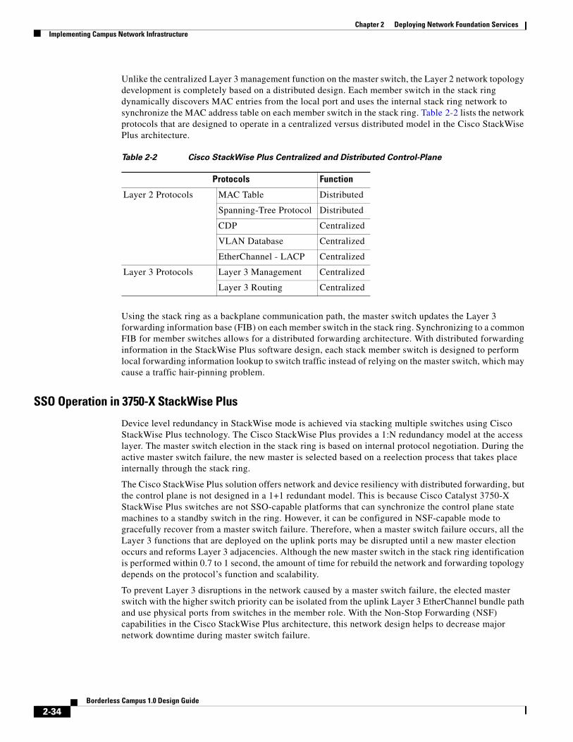
Chapter 2 Deploying Network Foundation ServicesImplementing Campus Network Infrastructure
Unlike the centralized Layer 3 management function on the master switch, the Layer 2 network topology development is completely based on a distributed design. Each member switch in the stack ring dynamically discovers MAC entries from the local port and uses the internal stack ring network to synchronize the MAC address table on each member switch in the stack ring. Table 2-2 lists the network protocols that are designed to operate in a centralized versus distributed model in the Cisco StackWise Plus architecture.
Using the stack ring as a backplane communication path, the master switch updates the Layer 3 forwarding information base (FIB) on each member switch in the stack ring. Synchronizing to a common FIB for member switches allows for a distributed forwarding architecture. With distributed forwarding information in the StackWise Plus software design, each stack member switch is designed to perform local forwarding information lookup to switch traffic instead of relying on the master switch, which may cause a traffic hair-pinning problem.
SSO Operation in 3750-X StackWise Plus
Device level redundancy in StackWise mode is achieved via stacking multiple switches using Cisco StackWise Plus technology. The Cisco StackWise Plus provides a 1:N redundancy model at the access layer. The master switch election in the stack ring is based on internal protocol negotiation. During the active master switch failure, the new master is selected based on a reelection process that takes place internally through the stack ring.
The Cisco StackWise Plus solution offers network and device resiliency with distributed forwarding, but the control plane is not designed in a 1+1 redundant model. This is because Cisco Catalyst 3750-X StackWise Plus switches are not SSO-capable platforms that can synchronize the control plane state machines to a standby switch in the ring. However, it can be configured in NSF-capable mode to gracefully recover from a master switch failure. Therefore, when a master switch failure occurs, all the Layer 3 functions that are deployed on the uplink ports may be disrupted until a new master election occurs and reforms Layer 3 adjacencies. Although the new master switch in the stack ring identification is performed within 0.7 to 1 second, the amount of time for rebuild the network and forwarding topology depends on the protocol’s function and scalability.
To prevent Layer 3 disruptions in the network caused by a master switch failure, the elected master switch with the higher switch priority can be isolated from the uplink Layer 3 EtherChannel bundle path and use physical ports from switches in the member role. With the Non-Stop Forwarding (NSF) capabilities in the Cisco StackWise Plus architecture, this network design helps to decrease major network downtime during master switch failure.
Table 2-2 Cisco StackWise Plus Centralized and Distributed Control-Plane
Protocols Function
Layer 2 Protocols MAC Table Distributed
Spanning-Tree Protocol Distributed
CDP Centralized
VLAN Database Centralized
EtherChannel - LACP Centralized
Layer 3 Protocols Layer 3 Management Centralized
Layer 3 Routing Centralized
2-34Borderless Campus 1.0 Design Guide
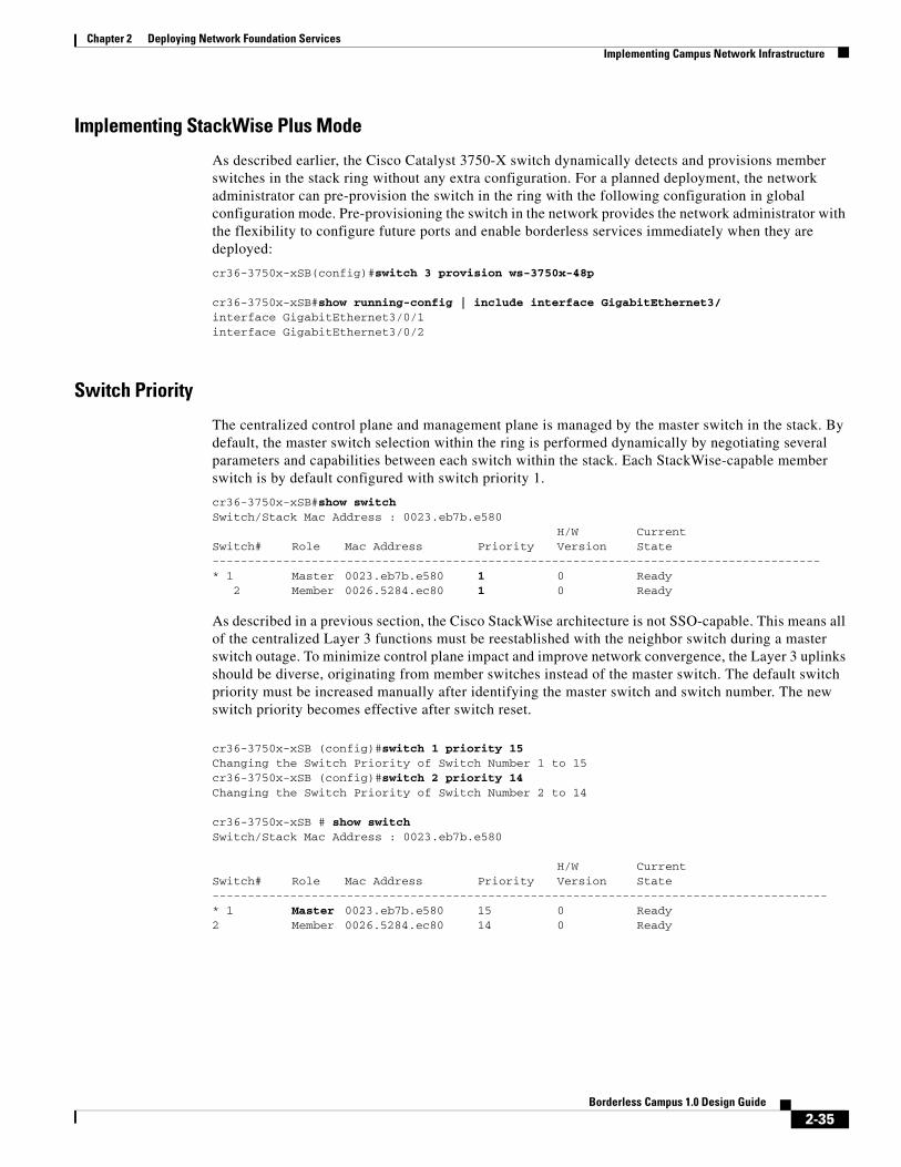
Chapter 2 Deploying Network Foundation ServicesImplementing Campus Network Infrastructure
Implementing StackWise Plus Mode
As described earlier, the Cisco Catalyst 3750-X switch dynamically detects and provisions member switches in the stack ring without any extra configuration. For a planned deployment, the network administrator can pre-provision the switch in the ring with the following configuration in global configuration mode. Pre-provisioning the switch in the network provides the network administrator with the flexibility to configure future ports and enable borderless services immediately when they are deployed:
cr36-3750x-xSB(config)#switch 3 provision ws-3750x-48p
cr36-3750x-xSB#show running-config | include interface GigabitEthernet3/interface GigabitEthernet3/0/1interface GigabitEthernet3/0/2
Switch Priority
The centralized control plane and management plane is managed by the master switch in the stack. By default, the master switch selection within the ring is performed dynamically by negotiating several parameters and capabilities between each switch within the stack. Each StackWise-capable member switch is by default configured with switch priority 1.
cr36-3750x-xSB#show switchSwitch/Stack Mac Address : 0023.eb7b.e580
H/W CurrentSwitch# Role Mac Address Priority Version State --------------------------------------------------------------------------------------* 1 Master 0023.eb7b.e580 1 0 Ready 2 Member 0026.5284.ec80 1 0 Ready
As described in a previous section, the Cisco StackWise architecture is not SSO-capable. This means all of the centralized Layer 3 functions must be reestablished with the neighbor switch during a master switch outage. To minimize control plane impact and improve network convergence, the Layer 3 uplinks should be diverse, originating from member switches instead of the master switch. The default switch priority must be increased manually after identifying the master switch and switch number. The new switch priority becomes effective after switch reset.
cr36-3750x-xSB (config)#switch 1 priority 15Changing the Switch Priority of Switch Number 1 to 15cr36-3750x-xSB (config)#switch 2 priority 14Changing the Switch Priority of Switch Number 2 to 14
cr36-3750x-xSB # show switchSwitch/Stack Mac Address : 0023.eb7b.e580
H/W CurrentSwitch# Role Mac Address Priority Version State ---------------------------------------------------------------------------------------* 1 Master 0023.eb7b.e580 15 0 Ready2 Member 0026.5284.ec80 14 0 Ready
2-35Borderless Campus 1.0 Design Guide

Chapter 2 Deploying Network Foundation ServicesImplementing Campus Network Infrastructure
Stack-MAC Address
To provide a single unified logical network view in the network, the MAC addresses of Layer 3 interfaces on the StackWise (physical, logical, SVIs, port channel) are derived from the Ethernet MAC address pool of the master switch in the stack. All Layer 3 communication from the StackWise switch to the endpoints (such as IP phones, PCs, servers, and core network system) is based on the MAC address pool of the master switch.
cr36-3750x-xSB#show switchSwitch/Stack Mac Address : 0023.eb7b.e580
H/W CurrentSwitch# Role Mac Address Priority Version State -------------------------------------------------------------------------------------* 1 Master 0023.eb7b.e580 15 0 Ready2 Member 0026.5284.ec80 14 0 Ready
cr36-3750s-xSB #show version. . .Base ethernet MAC Address : 00:23:EB:7B:E5:80. . .
To prevent network instability, the old MAC address assignments on Layer 3 interfaces can be retained even after the master switch fails. The new active master switch can continue to use the MAC addresses assigned by the old master switch, which prevents ARP and routing outages in the network. The default stack-mac timer settings must be changed in Catalyst 3750-X StackWise switch mode using the global configuration CLI mode as shown below:
cr36-3750x-xSB (config)#stack-mac persistent timer 0cr36-3750x-xSB #show switchSwitch/Stack Mac Address : 0026.5284.ec80 Mac persistency wait time: Indefinite H/W CurrentSwitch# Role Mac Address Priority Version State ----------------------------------------------------------------------------------* 1 Master 0023.eb7b.e580 15 0 Ready2 Member 0026.5284.ec80 14 0 Ready
Deploying Cisco Catalyst 3750-X and 3560-XThe Borderless Campus design recommends deploying fixed or standalone configuration Cisco Catalyst 3750-X and 3560-X Series platforms at the campus network edge. The hardware architecture of access layer fixed configuration switches is standalone and non-modular in design. These switches are designed to go above the traditional access layer switching function to provide robust next-generation network services (edge security, PoE+ EnergyWise, etc.).
Deploying Cisco Catalyst switches in standalone configuration mode does not require any system-specific configuration as they are ready to be deployed at the access layer with their default settings. All recommended access layer features and configuration are explained in the following sections.
2-36Borderless Campus 1.0 Design Guide

Chapter 2 Deploying Network Foundation ServicesImplementing Campus Network Infrastructure
Designing the Campus LAN NetworkIn this reference design, multiple parallel physical paths are recommended to build a highly-scalable and resilient foundation for an enterprise campus network. Depending on the system design and implementation, the default network configuration requires each network configuration, protocol adjacencies, and forwarding information on a per-interface basis to load share traffic and provide network redundancy.
Distributed Physical Path Network Design
As a general best practice to build resilient network designs, it is highly recommended to interconnect all network systems with full-mesh diverse physical paths. This network design automatically creates multiple parallel paths to provide load-sharing capabilities and path redundancy during network fault events. Deploying a single physical connection from any standalone campus system to separate redundant upstream systems creates a “triangle”-shaped physical network design that is an optimal and redundant design, in contrast to the non-recommended partial-mesh “square” physical network design. Utilizing the hardware resources for network connectivity varies based on the system type and the capabilities that are deployed in each campus layer.
Access Layer
The access layer Cisco Catalyst switching systems provide flexibility to scale network edge ports and have multiple high-speed 1G/10G uplink physical ports for network connectivity. The number of uplink ports may vary based on multiple factors, e.g., system type (standalone versus stack mode or redundant versus non-redundant supervisor). Independent of system type and deployment mode, Cisco recommends building full-mesh redundant physical paths in each design. Refer to Deploying Cisco Catalyst 4500E and Deploying Cisco Catalyst 3750-X StackWise Plus for uplink port design recommendation.
Distribution Core Layer
Campus distribution and core layer systems typically have modular hardware with centralized processing on a supervisor module and distributed forwarding on high-speed network modules. To enable end-to-end borderless network services, the campus core layer system interconnects to several sub-blocks of the network—data center, WAN edge, services block, etc. The fundamentals of building a resilient campus network design with diversified, distributed, and redundant physical paths does not vary by role, system, or deployed configuration mode. Figure 2-24 illustrates full-mesh redundant physical connections between a wide range of Cisco devices deployed in different campus, edge, and data center network tiers:
2-37Borderless Campus 1.0 Design Guide

Chapter 2 Deploying Network Foundation ServicesImplementing Campus Network Infrastructure
Figure 2-24 Redundant Campus Core and Edge Physical Path Design
Optimizing Campus Network Operation
While multiple redundant paths to redundant systems provides various benefits, it also introduces network design and operational challenges. Each system builds multiple protocol adjacencies, routing topologies, and forwarding information through each individual Layer 3 physical path. In a multilayer design, the distribution access layer network may operate at reduced capacity based on a loop-free Layer 2 network topology. Based on the recommended full-mesh campus LAN design and Cisco’s system virtualization technique, this guide provides guidance to simplify overall campus network operation.
Based on the campus network layer, system capability, and physical layout, the campus network can be designed and deployed in two different models—Equal Cost Multi Path (ECMP) and EtherChannel technology. Both deployment models can co-exist in a campus network, however Cisco recommends simplifying the campus network with EtherChannel when possible. Equal Cost Multi Path Network Design provides design and deployment guidance for both modes.
Equal Cost Multi Path Network Design
In simple terms, when a campus system develops best-path routing and forwarding tables to the same destination address through multiple next-hop devices, it is known as ECMP. In such a network design, the campus backbone network provides data traffic load balancing and path redundancy over full-mesh physical connections between each system. An ECMP network requires its own set of network policies, configuration, and tuning to develop distributed forwarding information across each physical connection.
SW1 SW2
Distribution
Core
Data Center/Services Block/Edge
Campus Core Physical Design –Cisco Catalyst 6500-E (VSS Mode)
Campus Core Physical Design –Cisco Nexus 7000
VSL
SW1 SW2
VSLCore-1
Dist-1
Data Center
QFP
PSTNWAN
2905
79
SW1 SW2
VSL
Nexus 7000
Core-2Core-1Distributed,Diversed end
RedundantPhysical Paths
Dist-1
Data Center
QFP
PSTNWAN
2-38Borderless Campus 1.0 Design Guide
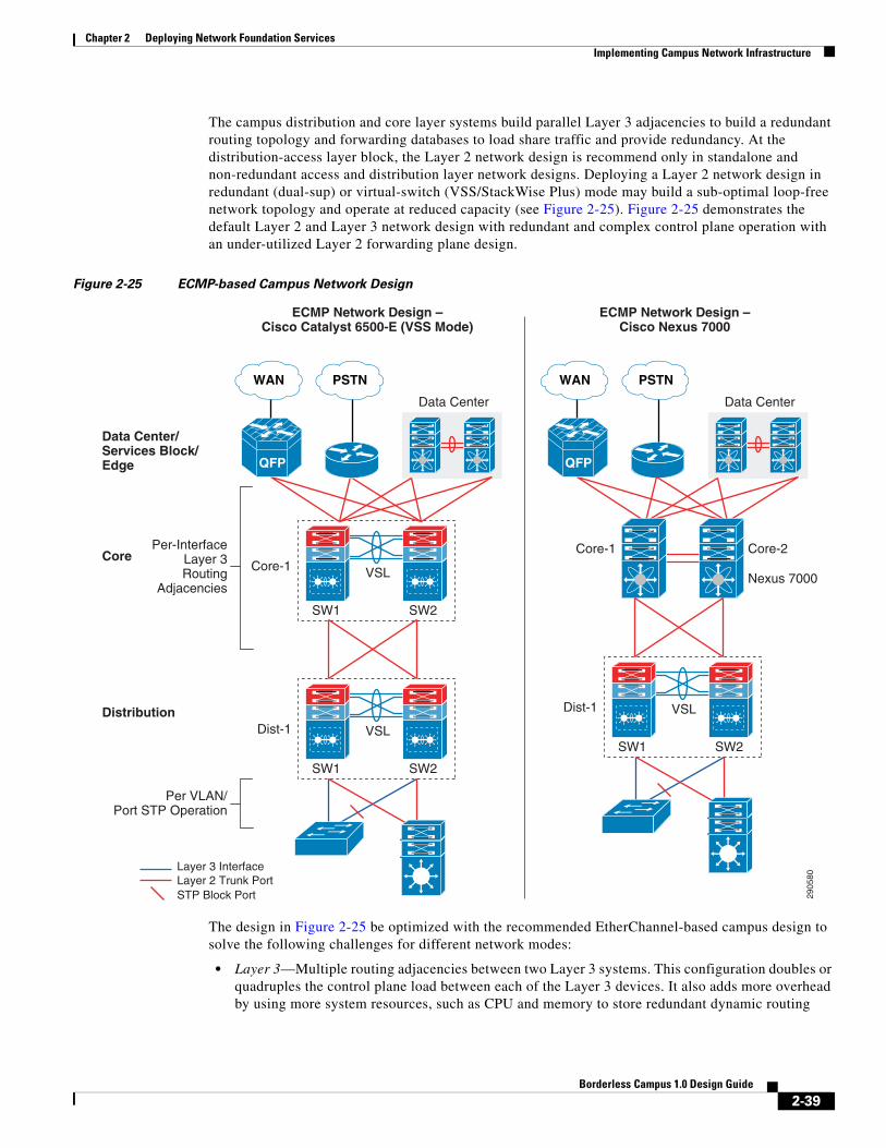
Chapter 2 Deploying Network Foundation ServicesImplementing Campus Network Infrastructure
The campus distribution and core layer systems build parallel Layer 3 adjacencies to build a redundant routing topology and forwarding databases to load share traffic and provide redundancy. At the distribution-access layer block, the Layer 2 network design is recommend only in standalone and non-redundant access and distribution layer network designs. Deploying a Layer 2 network design in redundant (dual-sup) or virtual-switch (VSS/StackWise Plus) mode may build a sub-optimal loop-free network topology and operate at reduced capacity (see Figure 2-25). Figure 2-25 demonstrates the default Layer 2 and Layer 3 network design with redundant and complex control plane operation with an under-utilized Layer 2 forwarding plane design.
Figure 2-25 ECMP-based Campus Network Design
The design in Figure 2-25 be optimized with the recommended EtherChannel-based campus design to solve the following challenges for different network modes:
• Layer 3—Multiple routing adjacencies between two Layer 3 systems. This configuration doubles or quadruples the control plane load between each of the Layer 3 devices. It also adds more overhead by using more system resources, such as CPU and memory to store redundant dynamic routing
SW1 SW2
Distribution
Core
Data Center/Services Block/Edge
ECMP Network Design –Cisco Catalyst 6500-E (VSS Mode)
ECMP Network Design –Cisco Nexus 7000
VSL
SW1 SW2
VSLCore-1
Dist-1
Data Center
QFP
PSTNWAN
2905
80
SW1 SW2
VSL
Nexus 7000
Core-2Core-1Per-InterfaceLayer 3Routing
Adjacencies
Dist-1
Data Center
QFP
PSTNWAN
Per VLAN/Port STP Operation
Layer 3 InterfaceLayer 2 Trunk PortSTP Block Port
2-39Borderless Campus 1.0 Design Guide

Chapter 2 Deploying Network Foundation ServicesImplementing Campus Network Infrastructure
information with different Layer 3 next-hop addresses connected to the same router. It develops Equal Cost Multi Path (ECMP) symmetric forwarding paths between the same Layer 3 peers and offers network scale-dependent, Cisco CEF-based network recovery.
• Layer 2—Multiple parallel Layer 2 paths between the STP Root (distribution) and the access switch will create a network loop. To a build loop-free network topology, the STP blocks the non-preferred individual link path from entering into a forwarding state. With a single STP root virtual switch, such network topologies cannot fully use all the network resources and creates a non-optimal and asymmetric traffic forwarding design.
• VSL Link Utilization—In a Cisco VSS-based distribution network, it is highly recommended to not create a hardware or network protocol-driven asymmetric forwarding design (e.g., single-home connection or STP block port). As described in Deploying Cisco Catalyst 6500-E in VSS Mode, VSL is not a regular network port; it is a special inter-chassis backplane connection used to build the virtual system and the network must be designed to switch traffic across VSL-only as a last resort.
ECMP Load-Sharing
In an ECMP-based campus network design, each campus system load shares the network data traffic based on multiple variables to utilize all symmetric forwarding paths installed in the routing information base (RIB). To load share traffic in a hardware path, each switch independently computes hash based on a variety of input information to program forwarding information in the hardware. Cisco Catalyst switches running IOS software leverage the Cisco Express Forwarding (CEF) switching algorithm for hardware-based destination lookup to provide wire-speed switching performance for a large-scale network design. Independent of IGP type, CEF uses the routing table to pre-program the forwarding path and build the forwarding information base (FIB) table. FIB installs multiple adjacencies if there are multiple paths in RIB. For wire-speed packet switching, the CEF also uses an adjacency table that contains Layer 2 egress header and rewrite encapsulation information.
Per-Flow Load Sharing
To efficiently distribute network traffic across all ECMP paths, Cisco IOS and NX-OS builds deterministic load share paths based on Layer 3 addresses (source-destination flow) and provides the ability to include Layer 4 port input information. By default the Cisco Catalyst and the Nexus 7000 system perform ECMP load balancing on a per-flow basis. Hence based on the locally-computed hash result, a flow may always take the same physical path to transmit egress traffic unless a preferred path from hash result is unavailable. In a large enterprise campus network design, it is assumed there is a good statistical mix of IP hosts, networks, and applications that allows aggregation and core layer systems to optimally load share traffic across all physical paths. While per-destination load sharing balances network traffic across multiple egress paths, it may not operate in deterministic mode to evenly distribute traffic across each link. However the load sharing mechanism ensures the flow pattern and path is maintained as it traverses through each campus network hop.
As every enterprise campus network runs a wide-range of applications, it is complex to unify and recommend a single ECMP load-balancing mechanism for all network designs. The network administrator may modify default settings to include source or destination IP address and Layer 4 port information for ECMP load balance hash computation if the campus system does not load balance traffic across all paths:
Catalyst 6500
Dist-VSS(config)#mls ip cef load-sharing full
Catalyst 4500E
cr19-4500-1(config)#ip cef load-sharing algorithm include-ports source destinationcr19-4500-1#show cef state | inc include
2-40Borderless Campus 1.0 Design Guide

Chapter 2 Deploying Network Foundation ServicesImplementing Campus Network Infrastructure
include-ports source destination per-destination load sharing algorithm
Nexus 7000
By default Cisco Nexus 7000 includes Layer 3 and Layer 4 port information in ECMP load sharing and it can be verified with following show command:
cr35-N7K-Core1# show ip load-sharing IPv4/IPv6 ECMP load sharing:Universal-id (Random Seed): 3839634274Load-share mode : address source-destination port source-destination
Per-Packet Load Sharing
Cisco CEF per-packet load sharing ensures that each ECMP path is evenly utilized and minimizes the under and overload link conditions caused by certain heavy data flows. The Cisco Catalyst switching system does not support per-packet load sharing. The Cisco Nexus 7000 can perform per-packet load sharing on a per-flow basis, i.e., same source and destination address. Per-packet load sharing cannot be done on every egress packet that contains a different source or destination network address. If a flow takes a separate core switching path, it is possible to receive packets out-of-order, which may impact network and application performance. As the campus core system switches data traffic for a wide-range of business critical communications and applications, it is recommended to retain default per-destination ECMP load sharing to minimize application and network instability.
EtherChannel Network Design
Traditionally campus networks were designed with standalone networks systems and ECMP, which did not, provided the flexibility to simplify network design with redundant devices or paths to logically act as a single entity. Campus network designs are evolving with Cisco’s system virtualization innovation in Catalyst switching platforms, such as VSS, StackWise Plus, or FlexStack, with redesign opportunities in all three tiers. While each of these virtualization techniques clusters multiple physical systems into a single large and unified logical system, the distributed multiple parallel physical paths can now be bonded into logical point-to-point EtherChannel interfaces between two systems. The principle of building a full-mesh physical campus network should not be changed when a campus device or link are implemented to operate in logical mode.
Designing a multilayer or campus backbone network with EtherChannel between two systems offers multiple benefits:
• Simplified—Bundling multiple ECMP paths into logical EtherChannel reduces redundant protocol adjacencies, routing databases, and forwarding paths.
• Optimize—Reduces the number of control plane operations and optimizes system resources, such as CPU/memory utilization, to store single upstream and downstream dynamic routing information instead of multiple versions without ECMP. Provides flexible Layer 2 to Layer 4 variables to intelligently load share and utilize all resources for network data traffic across each bundled interface.
• Reduce complexity—Simplifies network operational practice and reduces the amount of network configuration and troubleshooting required to analyze and debug problems.
• Increase capacity—Eliminates protocol-driven restrictions and doubles switching capacity in multilayer designs by utilizing all resources (bandwidth, queue, buffer, etc.) across all bundled Layer 2 uplinks.
• Resilient—Provides deterministic hardware-driven network recovery for seamless business operation. Minimizes routing database re-computation and topology changes during minor network faults, e.g., link failure.
2-41Borderless Campus 1.0 Design Guide
Chapter 2 Deploying Network Foundation ServicesImplementing Campus Network Infrastructure
In a standalone EtherChannel mode, multiple and diversified member links are physically connected in parallel between two physical systems. All the key network devices in the Borderless Campus design guide support EtherChannel technology. Independent of location in the network, whether in a campus layer, data center, or the WAN/Internet edge, the EtherChannel fundamentals and configuration guidelines described in this section remain consistent.
Multi-Chassis EtherChannel Fundamentals
Cisco’s Multi-Chassis EtherChannel (MEC) technology is a breakthrough innovation that creates logical point-to-point EtherChannels distributed across mulitple physical switches, which allows for a highly-resilient virtual switch in the VSS domain. Deploying Layer 2 or Layer 3 MEC with VSS introduces the following benefits:
• In addition to all EtherChannel benefits, the distributed forwarding architecture in MEC helps increase network bandwidth capacity.
• Increases network reliability by eliminating the single point-of-failure limitation compared to traditional EtherChannel technology.
• Simplifies the network control plane, topology, and system resources within a single logical bundled interface instead of multiple individual parallel physical paths.
• Independent of network scalability, MEC provides deterministic hardware-based subsecond network recovery.
• MEC technology on the Catalyst 6500 in VSS mode remains transparent to remote peer devices.
Cisco recommends designing the campus network to bundle parallel paths into logical EtherChannel or MEC in all layers when possible. The campus network can be deployed in a hybrid EtherChannel and ECMP network design if any device cannot logically bind interfaces.
Figure 2-26 illustrates the recommended end-to-end EtherChannel/MEC and hybrid-based borderless campus network design that simplifies end-to-end network control plane operation.
2-42Borderless Campus 1.0 Design Guide

Chapter 2 Deploying Network Foundation ServicesImplementing Campus Network Infrastructure
Figure 2-26 Recommended EtherChannel/MEC-based Campus Network Design
Implementing EtherChannel
In standalone EtherChannel mode, multiple and diversified member links are physically connected in parallel between two physical systems. All the key network devices in the Borderless Campus design support EtherChannel technology. Independent of campus location and network layer—campus, data center, WAN/Internet edge—all the EtherChannel fundamentals and configuration guidelines described in this section remain consistent.
Port-Aggregation Protocols
The member links of EtherChannel must join the port channel interface using Cisco PAgP+ or industry-standard LACP port aggregation protocols. Both protocols are designed to provide consistent link capabilities, however the Cisco PAgP+ protocol provides an additional solution advantage, dual-active detection. Implementing these protocols provides the following additional benefits:
• Ensures link aggregation parameter consistency and compatibility between two the systems.
SW1 SW2
EtherChannel/MEC Campus Network Design –Cisco Catalyst 6500-E (VSS Mode)
EtherChannel/MEC Campus Network Design –Cisco Nexus 7000
VSL
SW1 SW2
VSLCore-1
Dist-1
Data Center
QFP
PSTNWAN
2905
81
SW1 SW2
VSL
Nexus 7000Catalyst
6500 – VSS
Catalyst6500 – VSS
Catalyst6500 – VSS
Core-2Core-1
End-to-EndSingle
Point-to-PointEtherChannel/MEC Interface
Dist-1
Data Center
QFP
PSTNWAN
Layer 2 EtherChannel/MEC Trunk Port
Layer 3 ECMP Interface
Layer 3 EtherChannel/MEC Interface
ECMP
EtherChannel/MEC
EtherChannel/MEC
2-43Borderless Campus 1.0 Design Guide

Chapter 2 Deploying Network Foundation ServicesImplementing Campus Network Infrastructure
• Ensures compliance with aggregation requirements.
• Dynamically reacts to runtime changes and failures on local and remote Etherchannel systems.
• Detects and removes unidirectional links and multidrop connections from the Etherchannel bundle.
All Cisco Catalyst switching platforms support Cisco PAgP+ and industry-standard LACP protocols. If Cisco or any other vendor campus system does not support PAgP, it should be deployed with the industry-standard LACP link bundling protocol. Figure 2-27 illustrates configuration guidelines for Cisco PAgP+ or LACP protocols between two systems based on their software capabilities.
Figure 2-27 Network-Wide Port-Aggregation Protocol Deployment Guidelines
Port aggregation protocol support varies on the various Cisco platforms. Depending on each end of the EtherChannel device types, Cisco recommends deploying the port channel settings specified in Table 2-3.
SW1 SW2
VSL
SW1
ONPAgP
PAgP
PAgP PAgP LACP
LACP LACP
LACPLACPSW2
VSLCore-1
Dist-1
Data Center
QFP
PSTNWAN
2905
82
SW1 SW2
VSL
Nexus 7000Catalyst
6500 – VSS
Catalyst6500 – VSS
Catalyst6500 – VSS
Core-2Core-1
Dist-1
Data Center
QFP
PSTNWAN
PAgP PAgP LACP
Table 2-3 MEC Port-Aggregation Protocol Recommendation
Port-Agg Protocol Local Node Remote Node Bundle State
PAgP+ Desirable Desirable Operational
2-44Borderless Campus 1.0 Design Guide

Chapter 2 Deploying Network Foundation ServicesImplementing Campus Network Infrastructure
The implementation guidelines to deploy EtherChannel and MEC in Layer 2 or Layer 3 mode on all campus Cisco IOS and NX-OS operating systems are simple and consistent. The following sample configuration illustrates implementation of point-to-point Layer 3 EtherChannel or MEC on the Cisco Catalyst and the Nexus 7000 series systems:
• Cisco IOS
cr23-VSS-Core(config)#interface Port-channel 102cr23-VSS-Core(config-if)# ip address 10.125.0.14 255.255.255.254! Bundling single MEC diversed physical ports and module on per node basis.cr23-VSS-Core(config)#interface range Ten1/1/3 , Ten1/3/3 , Ten2/1/3 , Ten2/3/3cr23-VSS-Core(config-if-range)#channel-protocol pagpcr23-VSS-Core(config-if-range)#channel-group 102 mode desirable
cr23-VSS-Core#show etherchannel 102 summary | inc Te 102 Po102(RU) PAgP Te1/1/3(P) Te1/3/3(P) Te2/1/3(P) Te2/3/3(P) cr23-VSS-Core#show pagp 102 neighbor | inc TeTe1/1/3 cr24-4507e-MB 0021.d8f5.45c0 Te4/2 27s SC 10001 Te1/3/3 cr24-4507e-MB 0021.d8f5.45c0 Te3/1 28s SC 10001 Te2/1/3 cr24-4507e-MB 0021.d8f5.45c0 Te4/1 11s SC 10001 Te2/3/3 cr24-4507e-MB 0021.d8f5.45c0 Te3/2 11s SC 10001
• Cisco NX-OS
cr35-N7K-Core1(config)# interface port-channel101cr35-N7K-Core1(config-if)#description Connected to Dist-VSScr35-N7K-Core1(config-if)#ip address 10.125.10.1/31
cr35-N7K-Core1(config-if)# interface Eth1/2 , Eth2/2cr35-N7K-Core1(config-if-range)#channel-group 101 mode active! Bundling single EtherChannel diversed between I/O Modules.
cr35-N7K-Core1#show port-channel summary interface port-channel 101 | inc Eth101 Po101(RU) Eth LACP Eth1/2(P) Eth2/2(P) cr35-N7K-Core1#show lacp port-channel interface port-channel 101port-channel101 System Mac=f8-66-f2-e-17-41 Local System Identifier=0x8000,f8-66-f2-e-17-41 Admin key=0x64 Operational key=0x64 Partner System Identifier=0x8000,2-0-0-0-0-1 Operational key=0x3 Max delay=0 Aggregate or individual=1 Member Port List=2
LACP Active Active Operational
None 1 ON ON Operational
1. None or Static Mode EtherChannel configuration must be deployed in exceptional cases when remote nodes do not support either of the port aggregation protocols. To prevent network instability, the network administrator must implement static mode port channel with special attention that ensures no configuration incompatibility between bundled member link ports.
Table 2-3 MEC Port-Aggregation Protocol Recommendation
2-45Borderless Campus 1.0 Design Guide
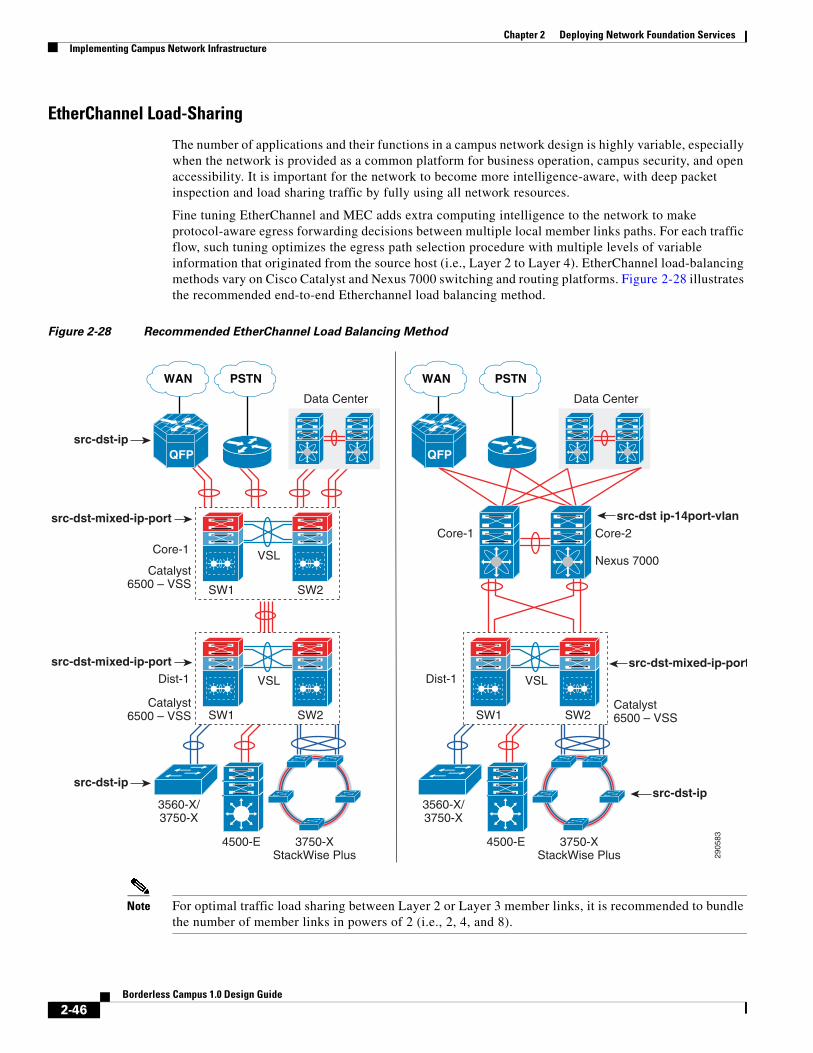
Chapter 2 Deploying Network Foundation ServicesImplementing Campus Network Infrastructure
EtherChannel Load-Sharing
The number of applications and their functions in a campus network design is highly variable, especially when the network is provided as a common platform for business operation, campus security, and open accessibility. It is important for the network to become more intelligence-aware, with deep packet inspection and load sharing traffic by fully using all network resources.
Fine tuning EtherChannel and MEC adds extra computing intelligence to the network to make protocol-aware egress forwarding decisions between multiple local member links paths. For each traffic flow, such tuning optimizes the egress path selection procedure with multiple levels of variable information that originated from the source host (i.e., Layer 2 to Layer 4). EtherChannel load-balancing methods vary on Cisco Catalyst and Nexus 7000 switching and routing platforms. Figure 2-28 illustrates the recommended end-to-end Etherchannel load balancing method.
Figure 2-28 Recommended EtherChannel Load Balancing Method
Note For optimal traffic load sharing between Layer 2 or Layer 3 member links, it is recommended to bundle the number of member links in powers of 2 (i.e., 2, 4, and 8).
SW1 SW2
VSL
SW1 SW2
3560-X/3750-X
4500-E 3750-XStackWise Plus
3560-X/3750-X
4500-E 3750-XStackWise Plus
VSLCore-1
Dist-1
Data Center
QFP
PSTNWAN
2905
83SW1 SW2
VSL
Nexus 7000Catalyst
6500 – VSS
Catalyst6500 – VSS
Catalyst6500 – VSS
Core-2Core-1
Dist-1
Data Center
QFP
PSTNWAN
src-dst ip-14port-vlan
src-dst-mixed-ip-port
src-dst-mixed-ip-port
src-dst-mixed-ip-port
src-dst-ip
src-dst-ip
src-dst-ip
2-46Borderless Campus 1.0 Design Guide

Chapter 2 Deploying Network Foundation ServicesImplementing Campus Network Infrastructure
Implementing EtherChannel Load-Sharing
EtherChannel load sharing is based on a polymorphic algorithm. On a per-protocol basis, load sharing is done based on source XOR destination address or port from Layer 2 to 4 header and ports. For higher granularity and optimal utilization of each member link port, an EtherChannel can intelligently load-share egress traffic using different algorithms.
All Cisco Catalyst switching and Cisco Nexus 7000 systems must be tuned with optimal EtherChannel load sharing capabilities similar to the following sample configuration:
Catalyst 3xxx and 4500-E
cr24-4507e-MB(config)#port-channel load-balance src-dst-ipcr24-4507e-MB#show etherchannel load-balanceEtherChannel Load-Balancing Configuration: src-dst-ip
Cisco Nexus 6500-E
cr23-VSS-Core(config)#port-channel load-balance src-dst-mixed-ip-portcr23-VSS-Core#show etherchannel load-balance EtherChannel Load-Balancing Configuration: src-dst-mixed-ip-port vlan included
Cisco Nexus 7000
cr35-N7K-Core1(config)#port-channel load-balance src-dst ip-l4port-vlancr35-N7K-Core1#show port-channel load-balancePort Channel Load-Balancing Configuration:System: src-dst ip-l4port-vlan
Implementing MEC Load-Sharing
The next-generation Catalyst 6500-E Sup720-10G supervisor introduces more intelligence and flexibility to load share traffic with up to 13 different traffic patterns. Independent of virtual switch role, each node in VSD uses the same polymorphic algorithm to load share egress Layer 2 or Layer 3 traffic across different member links from the local chassis. When computing the load-sharing hash, each virtual switch node includes the local physical ports of MEC instead of remote switch ports; this customized load sharing is designed to prevent traffic reroute over the VSL. It is recommended to implement the following MEC load sharing configuration in global configuration mode:
cr23-VSS-Core(config)#port-channel load-balance src-dst-mixed-ip-port
cr23-VSS-Core#show etherchannel load-balanceEtherChannel Load-Balancing Configuration: src-dst-mixed-ip-port vlan included
Note MEC load-sharing becomes effective only when each virtual switch node has more than one physical path in the same bundle interface.
MEC Hash Algorithm
Like MEC load sharing, the hash algorithm is computed independently by each virtual switch to perform load sharing via its local physical ports. Traffic load share is defined based on the number of internal bits allocated to each local member link port. The Cisco Catalyst 6500-E system in VSS mode assigns eight bits to every MEC; 8-bit can be represented as a 100 percent switching load. Depending on the number
2-47Borderless Campus 1.0 Design Guide

Chapter 2 Deploying Network Foundation ServicesNetwork Addressing Hierarchy
of local member link ports in a MEC bundle, the 8-bit hash is computed and allocated to each port for optimal load sharing results. Like the standalone network design, VSS supports the following EtherChannel hash algorithms:
• Fixed—Default setting. Keep the default if each virtual switch node has a single local member link port bundled in the same Layer 2/Layer 3 MEC (total of two ports in MEC).
• Adaptive—Best practice is to modify to adaptive hash method if each virtual switch node has greater than or equal to two physical ports in the same Layer2/Layer 3 MEC.
When deploying a full-mesh V-shaped, VSS-enabled campus core network, it is recommended to modify the default MEC hash algorithm from the default settings as shown in the following sample configuration:
cr23-VSS-Core(config)#port-channel hash-distribution adaptive
Modifying the MEC hash algorithm to adaptive mode requires the system to internally reprogram the hash result on each MEC. Therefore, plan for additional downtime to make the new configuration effective.
cr23-VSS-Core(config)#interface Port-channel 101cr23-VSS-Core(config-if)#shutdowncr23-VSS-Core(config-if)#no shutdown
cr23-VSS-Core#show etherchannel 101 detail | inc HashLast applied Hash Distribution Algorithm: Adaptive
Network Addressing HierarchyDeveloping a structured and hierarchical IP address plan is as important as any other design aspect of the borderless network. Identifying an IP addressing strategy for the entire network design is essential.
Note This section does not explain the fundamentals of TCP/IP addressing; for more details, see the many Cisco Press publications that cover this topic.
The following are key benefits of using hierarchical IP addressing:
• Efficient address allocation
– Hierarchical addressing provides the advantage of grouping all possible addresses contiguously.
– In non-contiguous addressing, a network can create addressing conflicts and overlapping problems, which may not allow the network administrator to use the complete address block.
• Improved routing efficiencies
– Building centralized main and remote campus site networks with contiguous IP addresses provides an efficient way to advertise summarized routes to neighbors.
– Route summarization simplifies the routing database and computation during topology change events.
– Reduces the network bandwidth used by routing protocols.
– Improves overall routing protocol performance by flooding fewer messages and improves network convergence time.
• Improved system performance
2-48Borderless Campus 1.0 Design Guide
Chapter 2 Deploying Network Foundation ServicesNetwork Foundational Technologies for LAN Design
– Reduces the memory needed to hold large-scale discontiguous and non-summarized route entries.
– Reduces CPU power required to re-compute large-scale routing databases during topology change events.
– Becomes easier to manage and troubleshoot.
– Helps in overall network and system stability.
Network Foundational Technologies for LAN DesignIn addition to a hierarchical IP addressing scheme, it is also essential to determine which areas of the campus design are Layer 2 or Layer 3 to determine whether routing or switching fundamentals need to be applied. The following applies to the three layers in a campus design model:
• Core layer—Because this is a Layer 3 network that interconnects several remote locations and shared devices across the network, choosing a routing protocol is essential at this layer.
• Distribution layer—The distribution block uses a combination of Layer 2 and Layer 3 switching to provide for the appropriate balance of policy and access controls, availability, and flexibility in subnet allocation and VLAN usage. Both routing and switching fundamentals need to be applied.
• Access layer—This layer is the demarcation point between network infrastructure and computing devices. This is designed for critical network edge functions to provide intelligent application and device-aware services, to set the trust boundary to distinguish applications, provide identity-based network access to protected data and resources, provide physical infrastructure services to reduce greenhouse emission, and so on. This subsection provides design guidance to enable various types of Layer 1 to Layer 3 intelligent services and to optimize and secure network edge ports.
The recommended routing or switching scheme of each layer is discussed in the following sections.
Designing the Core Layer NetworkBecause the core layer is a Layer 3 network, routing principles must be applied. Choosing a routing protocol is essential; routing design principles and routing protocol selection criteria are discussed in the following subsections.
Routing Design Principles
Although enabling routing functions in the core is a simple task, the routing blueprint must be well understood and designed before implementation, because it provides the end-to-end reachability path of the enterprise network. For an optimized routing design, the following three routing components must be identified and designed to allow more network growth and provide a stable network, independent of scale:
• Hierarchical network addressing—Structured IP network addressing in the borderless network where the LAN and/or WAN design are required to make the network scalable, optimal, and resilient.
• Routing protocol—Cisco IOS supports a wide range of Interior Gateway Protocols (IGPs). Cisco recommends deploying a single routing protocol across the borderless network infrastructure.
2-49Borderless Campus 1.0 Design Guide
Chapter 2 Deploying Network Foundation ServicesNetwork Foundational Technologies for LAN Design
• Hierarchical routing domain—Routing protocols must be designed in a hierarchical model that allows the network to scale and operate with greater stability. Building a routing boundary and summarizing the network minimizes the topology size and synchronization procedure, which improves overall network resource use and re-convergence.
Routing Protocol Selection Criteria
The criteria for choosing the right protocol vary based on the end-to-end network infrastructure. Although all the routing protocols that Cisco IOS and NX-OS currently support can provide a viable solution, network architects must consider all of the following critical design factors when selecting the routing protocol to be implemented throughout the internal network:
• Network design—Requires a proven protocol that can scale in full-mesh campus network designs and can optimally function in hub-and-spoke WAN network topologies.
• Scalability—The routing protocol function must be network- and system-efficient and operate with a minimal number of updates and re-computation, independent of the number of routes in the network.
• Rapid convergence—Link-state versus DUAL re-computation and synchronization. Network re-convergence also varies based on network design, configuration, and a multitude of other factors that may be more than a specific routing protocol can handle. The best convergence time can be achieved from a routing protocol if the network is designed to the strengths of the protocol.
• Operational—A simplified routing protocol that can provide ease of configuration, management, and troubleshooting.
Cisco IOS and NX-OS support a wide range of routing protocols, such as Routing Information Protocol (RIP) v1/2, Enhanced Interior Gateway Routing Protocol (EIGRP), Open Shortest Path First (OSPF), and Intermediate System-to-Intermediate System (IS-IS). However, Cisco recommends using EIGRP or OSPF for this network design. EIGRP is a popular version of an Interior Gateway Protocol (IGP) because it has all the capabilities needed for small- to large-scale networks, offers rapid network convergence, and above all is simple to operate and manage. OSPF is a popular link state protocol for large-scale enterprise and service provider networks. OSPF enforces hierarchical routing domains in two tiers by implementing backbone and non-backbone areas. The OSPF area function depends on the network connectivity model and the role of each OSPF router in the domain.
Other technical factors must be considered when implementing OSPF in the network, such as OSPF router type, link type, maximum transmission unit (MTU) considerations, designated router (DR)/backup designated router (BDR) priority, and so on. This document provides design guidance for using simplified EIGRP and OSPF in the borderless network infrastructure.
Note For detailed information on EIGRP and OSPF, see: http://www.cisco.com/en/US/docs/solutions/Enterprise/Campus/routed-ex.html.
Designing EIGRP Routing in the Campus NetworkEIGRP is a balanced hybrid routing protocol that builds neighbor adjacency and flat routing topology on a per-autonomous system (AS) basis. Cisco recommends considering the following three critical design tasks before implementing EIGRP in the campus core layer network:
2-50Borderless Campus 1.0 Design Guide
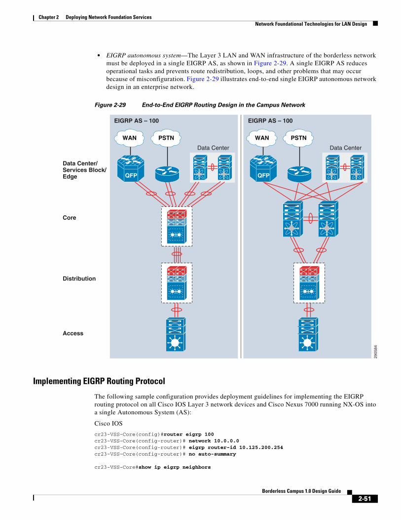
Chapter 2 Deploying Network Foundation ServicesNetwork Foundational Technologies for LAN Design
• EIGRP autonomous system—The Layer 3 LAN and WAN infrastructure of the borderless network must be deployed in a single EIGRP AS, as shown in Figure 2-29. A single EIGRP AS reduces operational tasks and prevents route redistribution, loops, and other problems that may occur because of misconfiguration. Figure 2-29 illustrates end-to-end single EIGRP autonomous network design in an enterprise network.
Figure 2-29 End-to-End EIGRP Routing Design in the Campus Network
Implementing EIGRP Routing Protocol
The following sample configuration provides deployment guidelines for implementing the EIGRP routing protocol on all Cisco IOS Layer 3 network devices and Cisco Nexus 7000 running NX-OS into a single Autonomous System (AS):
Cisco IOS
cr23-VSS-Core(config)#router eigrp 100cr23-VSS-Core(config-router)# network 10.0.0.0cr23-VSS-Core(config-router)# eigrp router-id 10.125.200.254cr23-VSS-Core(config-router)# no auto-summary
cr23-VSS-Core#show ip eigrp neighbors
2905
84
Distribution
Access
Core
Data Center/Services Block/Edge
EIGRP AS – 100 EIGRP AS – 100
Data Center
QFP
PSTNWAN
Data Center
QFP
PSTNWAN
2-51Borderless Campus 1.0 Design Guide

Chapter 2 Deploying Network Foundation ServicesNetwork Foundational Technologies for LAN Design
EIGRP-IPv4 neighbors for process 100H Address Interface Hold Uptime SRTT RTO Q Seq (sec) (ms) Cnt Num7 10.125.0.13 Po101 12 3d16h 1 200 0 620 10.125.0.15 Po102 10 3d16h 1 200 0 5031 10.125.0.17 Po103 11 3d16h 1 200 0 52…
cr23-VSS-Core#show ip route eigrp | inc /16|/20|0.0.0.0 10.0.0.0/8 is variably subnetted, 41 subnets, 5 masksD 10.126.0.0/16 [90/3072] via 10.125.0.23, 08:33:16, Port-channel106D 10.125.128.0/20 [90/3072] via 10.125.0.17, 08:33:15, Port-channel103D 10.125.96.0/20 [90/3072] via 10.125.0.13, 08:33:18, Port-channel101D 10.125.0.0/16 is a summary, 08:41:12, Null0…D*EX 0.0.0.0/0 [170/515072] via 10.125.0.27, 08:33:20, Port-channel108
Cisco NX-OS
cr35-N7K-Core1(config)#feature eigrp!Enable EIGRP feature set
cr35-N7K-Core1(config)# router eigrp 100cr35-N7K-Core1(config-router)# router-id 10.125.100.3!Configure system-wide EIGRP RID, auto-summarization is by default off in Cisco NX-OS
cr35-N7K-Core1(config)# interface Port-channel 100-103cr35-N7K-Core1(config-if-range)#ip router eigrp 100!Associate EIGRP routing process on per L3 Port-channel interface basis
cr35-N7K-Core1(config)# interface Ethernet 1/3-4cr35-N7K-Core1(config-if-range)#ip router eigrp 100!Associate EIGRP routing process on per L3 interface basis
cr35-N7K-Core1#show ip eigrp neighborIP-EIGRP neighbors for process 100 VRF defaultH Address Interface Hold Uptime SRTT RTO Q Seq (sec) (ms) Cnt Num5 10.125.10.0 Po101 12 00:05:18 2 200 0 834 10.125.12.4 Po103 12 00:05:19 3 200 0 893 10.125.12.0 Po102 13 00:05:19 1 200 0 1132 10.125.11.0 Eth1/3 14 00:05:19 1 200 0 751 10.125.11.4 Eth1/4 12 00:05:19 1 200 0 720 10.125.21.1 Po100 14 00:05:20 1 200 0 151
• EIGRP adjacency protection—This increases network infrastructure efficiency and protection by securing the EIGRP adjacencies with internal systems. This task involves two subset implementation tasks on each EIGRP-enabled network device:
– Increases system efficiency—Blocks EIGRP processing with passive-mode configuration on physical or logical interfaces connected to non-EIGRP devices in the network, such as PCs. The best practice helps reduce CPU utilization and secures the network with unprotected EIGRP adjacencies with untrusted devices. The following sample configuration provides guidelines to enable EIGRP protocol communication on trusted interfaces and block on all system interfaces. This recommended best practice must be enabled on all of the EIGRP Layer 3 systems in the network:
Cisco IOS
cr23-VSS-Core(config)#router eigrp 100cr23-VSS-Core(config-router)# passive-interface defaultcr23-VSS-Core(config-router)# no passive-interface Port-channel101
2-52Borderless Campus 1.0 Design Guide
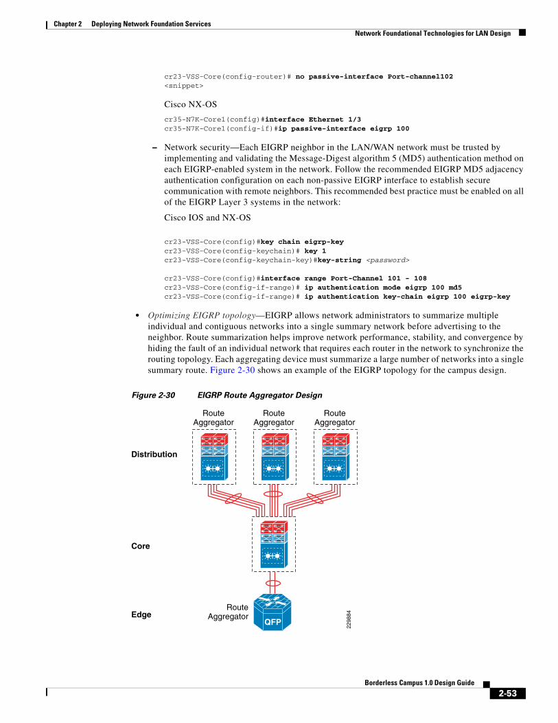
Chapter 2 Deploying Network Foundation ServicesNetwork Foundational Technologies for LAN Design
cr23-VSS-Core(config-router)# no passive-interface Port-channel102<snippet>
Cisco NX-OS
cr35-N7K-Core1(config)#interface Ethernet 1/3cr35-N7K-Core1(config-if)#ip passive-interface eigrp 100
– Network security—Each EIGRP neighbor in the LAN/WAN network must be trusted by implementing and validating the Message-Digest algorithm 5 (MD5) authentication method on each EIGRP-enabled system in the network. Follow the recommended EIGRP MD5 adjacency authentication configuration on each non-passive EIGRP interface to establish secure communication with remote neighbors. This recommended best practice must be enabled on all of the EIGRP Layer 3 systems in the network:
Cisco IOS and NX-OS
cr23-VSS-Core(config)#key chain eigrp-keycr23-VSS-Core(config-keychain)# key 1cr23-VSS-Core(config-keychain-key)#key-string <password>
cr23-VSS-Core(config)#interface range Port-Channel 101 - 108cr23-VSS-Core(config-if-range)# ip authentication mode eigrp 100 md5cr23-VSS-Core(config-if-range)# ip authentication key-chain eigrp 100 eigrp-key
• Optimizing EIGRP topology—EIGRP allows network administrators to summarize multiple individual and contiguous networks into a single summary network before advertising to the neighbor. Route summarization helps improve network performance, stability, and convergence by hiding the fault of an individual network that requires each router in the network to synchronize the routing topology. Each aggregating device must summarize a large number of networks into a single summary route. Figure 2-30 shows an example of the EIGRP topology for the campus design.
Figure 2-30 EIGRP Route Aggregator Design
Distribution
Core
Edge
2298
84
RouteAggregator
RouteAggregator
RouteAggregator
RouteAggregator
QFP
2-53Borderless Campus 1.0 Design Guide

Chapter 2 Deploying Network Foundation ServicesNetwork Foundational Technologies for LAN Design
The following configuration must be applied on each EIGRP route aggregator system as depicted in Figure 2-30. EIGRP route summarization must be implemented on the upstream logical port channel interface to announce a single prefix from each block.
Distribution
cr22-6500-LB(config)#interface Port-channel100cr22-6500-LB(config-if)# ip summary-address eigrp 100 10.125.96.0 255.255.240.0
cr22-6500-LB#show ip protocols… Address Summarization: 10.125.96.0/20 for Port-channel100<snippet>
cr22-6500-LB#s ip route | inc Null0D 10.125.96.0/20 is a summary, 3d16h, Null0
• EIGRP Timers—By default, EIGRP speakers running Cisco IOS or NX-OS systems transmit Hello packets every five seconds and terminate EIGRP adjacency if the neighbor fails to receive it within 15 seconds of hold-down time. In this network design, Cisco recommends retaining the default EIGRP Hello and Hold timers on all EIGRP-enabled platforms. Implementing aggressive EIGRP Hello processing and Hold-down timers may create adverse impacts during graceful recovery processes on any of the redundant campus layer systems.
Designing OSPF Routing in the Campus NetworkOSPF is a widely-deployed IETF standard link state and adaptive routing protocol for the heterogeneous vendor enterprise network environment. Unlike the EIGRP protocol, the OSPF network builds a structured network boundary into multiple areas, which helps in propagating summarized network topology information and rapidly performs OSPF database computations for intelligent forwarding decisions. OSPF divides the routing boundaries into non-backbone areas that connect to single core backbone area; such design helps simplify administration and optimizes network traffic and resource utilization. The OSPF protocol supports various types of areas; this design guide recommends the following two areas types to implement in an enterprise campus network (see Figure 2-31):
• Backbone area—The campus core layer is the heart of the network backbone and it must be configured with OSPF backbone area. The campus aggregation layer system must be implemented in the Area Border Router (ABR) role that interconnects to the core backbone area and to the access layer non-backbone area OSPF systems. Cisco recommends that OSPF routing and backbone area design be contiguous.
• Stub/Totally Stub area—The campus access layer network requires concise network topology information and the default route from the distribution layer systems to reach external networks. Hence the non-OSPF backbone area between the distribution and access layer must be configured into stub area or totally stub area mode. Only the non-backbone area can be deployed into stub or totally-stub area mode. For a summarized network topology, these area types do not receive external route information from an area border router. Totally-stub area is a Cisco proprietary area type and an extension to an IETF standard stub area. Cisco’s totally-stubby area is the same as stub area, however it does not allow a summarized network and external route to reduce the OSPF database size.
2-54Borderless Campus 1.0 Design Guide

Chapter 2 Deploying Network Foundation ServicesNetwork Foundational Technologies for LAN Design
Figure 2-31 End-to_End Routing Design in the Campus Network
Implementing OSPF Routing Protocol
The following sample configuration provides deployment guidelines for implementing the OSPF routing protocol in the OSPF backbone area:
Core
Cisco IOS
cr23-VSS-Core(config)#router ospf 100cr23-VSS-Core(config-router)#router-id 10.125.200.254cr23-VSS-Core(config-router)#network 10.125.0.0 0.0.255.255 area 0!All connected interfaces configured in OSPF backbone area 0
Cisco NX-OS
cr35-N7K-Core1(config)# feature ospf!Enable OSPFv2 feature set
cr35-N7K-Core1(config)#router ospf 100cr35-N7K-Core1(config-router)#router-id 10.125.100.3cr35-N7K-Core1(config-router)#log-adjacency-changes detail!Configure OSPF routing instance and router-id for this system
2905
85
Distribution
Access
Core
Data Center/Services Block/Edge
Area 0 Area 0
Data Center
QFP
PSTNWAN
QFP
PSTNWAN
Data Center
Totally Stub Area
Backbone Area
Area 10 Area 20 Area 30 Area 10 Area 20 Area 30
2-55Borderless Campus 1.0 Design Guide

Chapter 2 Deploying Network Foundation ServicesNetwork Foundational Technologies for LAN Design
cr35-N7K-Core1(config)#interface loopback0cr35-N7K-Core1(config-if)#ip router ospf 100 area 0.0.0.0
cr35-N7K-Core1(config)#interface eth1/1 , et2/1cr35-N7K-Core1(config-if)#ip router ospf 100 area 0.0.0.0
cr35-N7K-Core1(config)#interface port-channel 100 - 103cr35-N7K-Core1(config-if)#ip router ospf 100 area 0.0.0.0!Associate OSPF process and area-id on per-interface basis
Distributioncr22-6500-LB(config)#router ospf 100cr22-6500-LB(config-router)# router-id 10.125.200.6cr22-6500-LB(config-router)#network 10.125.200.6 0.0.0.0 area 0cr22-6500-LB(config-router)#network 10.125.0.13 0.0.0.0 area 0!Loopback and interface connected to Core router configured in OSPF backbone area 0
cr22-6500-LB#show ip ospf neighbor!OSPF adjacency between Distribution and Core successfully established
Neighbor ID Pri State Dead Time Address Interface10.125.200.254 1 FULL/DR 00:00:38 10.125.0.12 Port-channel101
…..
• OSPF adjacency protection—Like EIGRP routing security, these best practices increase network infrastructure efficiency and protection by securing the OSPF adjacencies with internal systems. This task involves two subset implementation tasks on each OSPF-enabled network device:
– Increases system efficiency—Blocks OSPF processing with passive-mode configuration on physical or logical interfaces connected to non-OSPF devices in the network, such as PCs. The best practice helps reduce CPU utilization and secures the network with unprotected OSPF adjacencies with untrusted neigbors. The following sample configuration provides guidelines to explicitly enable OSPF protocol communication on trusted interfaces and block on all other interfaces. This recommended best practice must be enabled on all of the OSPF Layer 3 systems in the network:
Cisco IOS
cr22-6500-LB(config)#router ospf 100cr22-6500-LB(config-router)# passive-interface defaultcr22-6500-LB(config-router)# no passive-interface Port-channel101
Cisco NX-OS
cr35-N7K-Core1(config)#interface Ethernet 1/3cr35-N7K-Core1(config-if)#ip ospf passive-interface
– Network security—Each OSPF neighbor in the LAN/WAN network must be trusted by implementing and validating the Message-Digest algorithm 5 (MD5) authentication methods on each OSPF-enabled system in the network. The following recommended OSPF MD5 adjacency authentication configuration must be in the OSPF backbone and each non-backbone area to establish secure communication with remote neighbors. This recommended best practice must be enabled on all of the OSPF Layer 3 systems in the network:
Cisco IOS and NX-OS
cr22-6500-LB(config)#router ospf 100cr22-6500-LB (config-router)#area 0 authentication message-digestcr22-6500-LB (config-router)#area 10 authentication message-digest!Enables common OSPF MD5 authentication method for all interfaces
cr22-6500-LB(config)#interface Port-Channel 101cr22-6500-LB(config-if-range)# ip ospf message-digest-key 1 <key>
2-56Borderless Campus 1.0 Design Guide

Chapter 2 Deploying Network Foundation ServicesNetwork Foundational Technologies for LAN Design
cr22-6500-LB#show ip ospf interface Port-channel101 | inc authen|key Message digest authentication enabled Youngest key id is 1
• Optimizing OSPF topology—Depending on the network design, the OSPF protocol may be required to be fine-tuned in several aspects. Building borderless enterprise campus networks with Cisco VSS and Nexus 7000 with the recommended best practices inherently optimizes several routing components. Leveraging the underlying virtualized campus network benefits, this design guide recommends two fine-tuning parameters to be applied on OSPF-enabled systems:
– Route Aggregation—OSPF route summarization must be performed at the area border routers (ABR) that connect the OSPF backbone and several aggregated non-backbone; typically ABR routers are the campus distribution or WAN aggregation systems. Route summarization helps network administrators to summarize multiple individual and contiguous networks into a single summary network before advertising into the OSPF backbone area. Route summarization helps improve network performance, stability, and convergence by hiding the fault of an individual network that requires each router in the network to synchronize the routing topology. Refer to Figure 2-30 for an example of OSPF route aggregation topology in the enterprise campus design.
Distribution
!Route Aggregation on distribution layer OSPF ABR routercr22-6500-LB(config)#router ospf 100cr22-6500-LB(config-router)# area <non-backbone area> range <subnet> <mask>
– Network Type—OSPF supports several network types, each designed to operate optimally in various types of network connectivity and designs. The default network type for the OSPF protocol running over an Ethernet-based network is broadcast. Ethernet is a multi-acccess network that provides the flexibility to interconnect several OSPF neighbors deployed in a single Layer 2 broadcast domain. In a best practice campus network design, two Layer 3 systems interconnect directly to each other, thus forming point-to-point communication. Cisco recommends modifying the default OSPF network type from broadcast to point-to-point on systems running Cisco IOS and NX-OS, which optimizes adjacencies by eliminating DR/BDR processing and reducing routing complexities between all OSPF-enabled systems:
Cisco IOS and NX-OS
cr22-6500-LB #show ip ospf interface Port-channel 101 | inc Network Process ID 100, Router ID 10.125.100.2, Network Type BROADCAST, Cost: 1
cr22-6500-LB#show ip ospf neighbor!OSPF negotiates DR/BDR processing on Broadcast network
Neighbor ID Pri State Dead Time Address Interface10.125.200.254 1 FULL/DR 00:00:38 10.125.0.12 Port-channel101
cr22-6500-LB (config)#interface Port-channel 101cr22-6500-LB (config-if)#ip ospf network point-to-point
cr22-6500-LB#show ip ospf neighbor!OSPF point-to-point network optimizes adjacency processing
Neighbor ID Pri State Dead Time Address Interface10.125.200.254 1 FULL/ - 00:00:32 10.125.0.12 Port-channel101
• OSPF Hello Timers—By default, OSPF routers transmit Hello packets every 10 seconds and terminate OSPF adjacency if the neighbor fails to receive it within four intervals or 40 seconds of dead time. In this optimized and best practice network design, Cisco recommends to retain default OSPF Hello and Hold timers on all OSPF-enabled platforms running Cisco IOS or NX-OS operating systems. Implementing aggressive Hello processing timers and Dead Times may adversely impact graceful recovery processes on any of the redundant campus layer systems.
2-57Borderless Campus 1.0 Design Guide

Chapter 2 Deploying Network Foundation ServicesNetwork Foundational Technologies for LAN Design
• OSPF Auto-Cost—The metric of an OSPF interface determines the best forwarding path based on lower metric or cost to the destination. By default, the metric or cost of an OSPF interface is automatically derived based on a fixed formula (108/bandwidth in bps) on Cisco Catalyst switches running IOS software. For example, the OSPF cost for 10 Gbps link is computed as 1. In the EtherChannel/MEC-based network design, bundling multiple 10Gbps links into a logical port channel interface dynamically increases the aggregated bandwidth, however the OSPF cost remains 1 due to the fixed formula:
Cisco IOS
Dist-VSS#show interface Port-Channel 3 | inc BW|Member MTU 1500 bytes, BW 20000000 Kbit, DLY 10 usec, Members in this channel: Te1/1/8 Te2/1/8
Dist-VSS#show ip ospf interface Port-Channel 3 | inc Cost Process ID 100, Router ID 10.125.100.2, Network Type POINT_TO_POINT, Cost: 1
The default OSPF auto-cost can be adjusted if required, however it is recommended to maintain the default reference cost value on all OSPF switches running Cisco IOS. In a best practice enterprise campus network design, the default OSPF auto cost parameter helps minimize OSPF topology change and maintains network capacity and reliability during individual EtherChannel/MEC member links.
In the Cisco NX-OS, the default OSPF auto-cost reference bandwidth is 4010/bandwidth in bps or 40000 Mbps. Hence by default the OSPF metric of port channel interface can reflect the actual value based on the number of aggregated ports. With up to four 10Gbps interfaces bundled in EtherChannel, the Cisco Nexus 7000 can dynamically adjust the OSPF cost based on aggregated port channel interface bandwidth:
Cisco NX-OS
cr35-N7K-Core1#show ip ospf | inc Ref Reference Bandwidth is 40000 Mbps
cr35-N7K-Core1#show interface Port-Channel 101 | inc BW|Members MTU 1500 bytes, BW 20000000 Kbit, DLY 10 usec
Members in this channel: Eth1/2, Eth2/2cr35-N7K-Core1#show ip ospf int Port-Channel 101 | inc cost
State P2P, Network type P2P, cost 2
In the EtherChannel-based campus network design, the default auto-cost reference value on Cisco Nexus 7000 systems should be adjusted to the same as Cisco IOS software. Reverting the default OSPF auto-cost setting to the same as Cisco IOS provides multiple benefits as described earlier. Figure 2-32 illustrates the network data forwarding impact during individual link loss with default auto-cost setting and with 10000 Mbps setting.
2-58Borderless Campus 1.0 Design Guide
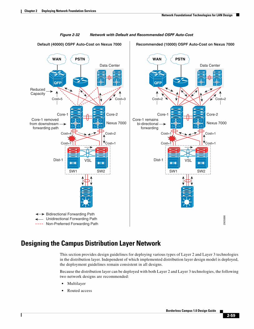
Chapter 2 Deploying Network Foundation ServicesNetwork Foundational Technologies for LAN Design
Figure 2-32 Network with Default and Recommended OSPF Auto-Cost
Designing the Campus Distribution Layer NetworkThis section provides design guidelines for deploying various types of Layer 2 and Layer 3 technologies in the distribution layer. Independent of which implemented distribution layer design model is deployed, the deployment guidelines remain consistent in all designs.
Because the distribution layer can be deployed with both Layer 2 and Layer 3 technologies, the following two network designs are recommended:
• Multilayer
• Routed access
Default (40000) OSPF Auto-Cost on Nexus 7000 Recommended (10000) OSPF Auto-Cost on Nexus 7000
2905
886
SW1 SW2
VSL
Nexus 7000
Core-2
Bidirectional Forwarding Psth Unidirectional Forwarding Path Non-Preferred Forwarding Path
Dist-1
Data Center
QFP
PSTNWAN
Core-1
SW1 SW2
VSL
Nexus 7000
Core-2
Cost=2
Cost=1
Cost=4
Cost=1
Dist-1
Data Center
QFP
PSTNWAN
Core-1
ReducedCapacity
Core-1 removedfrom downstream
forwarding path
Core-1 remainsbi-directional
forwardingCost=1
Cost=1
Cost=1
Cost=1
Cost=2Cost=2Cost=3Cost=5
2-59Borderless Campus 1.0 Design Guide

Chapter 2 Deploying Network Foundation ServicesNetwork Foundational Technologies for LAN Design
Designing the Multilayer Network
A multilayer network is a traditional, simple, and widely-deployed scenario, regardless of network scale. The access layer switches in the campus network edge interface with various types of endpoints and provide intelligent Layer 1/Layer 2 services. The access layer switches interconnect to distribution switches with the Layer 2 trunk and rely on the distribution layer aggregation switch to perform intelligent Layer 3 forwarding and to set policies and access control.
There are three design variations in building a multilayer network; all variations must be deployed in a V-shaped physical network design and must be built to provide a loop-free topology:
• Flat—Certain applications and user access require that the broadcast domain design span more than a single wiring closet switch. The multilayer network design provides the flexibility to build a single large broadcast domain with an extended star topology. Such flexibility introduces scalability, performance, and security challenges and may require extra attention to protect the network against misconfiguration and miswiring that can create spanning-tree loops and de-stabilize the network.
• Segmented—Provides a unique VLAN for different organizational divisions and enterprise business functional segments to build a per-department logical network. All network communication between various enterprise and administrative groups passes through the routing and forwarding policies defined at the distribution layer.
• Hybrid—A hybrid logical network design segments VLAN workgroups that do not span different access layer switches and allows certain VLANs (for example, that network management VLAN) to span across the access-distribution block. The hybrid network design enables flat Layer 2 communication without impacting the network and also helps reduce the number of subnets used.
Figure 2-33 shows the three design variations for the multilayer network.
Figure 2-33 Multilayer Design Variations
Cisco recommends that the hybrid multilayer access-distribution block design use a loop-free network topology and span a few VLANs that require such flexibility, such as the management VLAN.
VLAN10
VLAN10
VLAN10
Marketing Sales Engineering Marketing Sales Engineering Marketing Sales Engineering
Single Loop-freeEtherChannel
V-ShapeNetwork
Single RootBridge
2298
86
VLAN10
VLAN20
VLAN30
Multi-Layer –Segmented VLAN
VLAN10
VLAN20
VLAN30
VLAN 900
Network Mangement
Multi-Layer – Hybrid NetworkMulti-Layer – Flat Network
2-60Borderless Campus 1.0 Design Guide

Chapter 2 Deploying Network Foundation ServicesNetwork Foundational Technologies for LAN Design
The following sample configuration provides guideline to deploy several types of multilayer network components for the hybrid multilayer access-distribution block. All the configurations and best practices remain consistent and can deployed independent of Layer 2 platform type and campus location:
VTP
VLAN Trunking Protocol (VTP) is a Cisco proprietary Layer 2 messaging protocol that manages the addition, deletion, and renaming of VLANs on a network-wide basis. Cisco’s VTP simplifies administration in a switched network. VTP can be configured in three modes—server, client, and transparent. It is recommended to deploy VTP in transparent mode; set the VTP domain name and change the mode to the transparent mode as follows:
cr22-3750-LB(config)#vtp domain Campus-BNcr22-3750-LB(config)#vtp mode transparentcr22-3750-LB(config)#vtp version 2
cr22-3750-LB#show vtp statusVTP Version capable:1 to 3VTP version running:2VTP Domain Name:Campus-BN
VLANcr22-3750-LB(config)#vlan 101cr22-3750-LB(config-vlan)#name Untrusted_PC_VLANcr22-3750-LB(config)#vlan 102cr22-3750-LB(config-vlan)#name Lobby_IP_Phone_VLANcr22-3750-LB(config)#vlan 900cr22-3750-LB(config-vlan)#name Mgmt_VLAN
cr22-3750-LB#show vlan | inc 101|102|900101 Untrusted_PC_VLANactive Gi1/0/1102 Lobby_IP_Phone_VLANactive Gi1/0/2900 Mgmt_VLANactive
Implementing Layer 2 Trunk
In a typical campus network design, a single access switch is deployed with more than a single VLAN, such as a data VLAN and a voice VLAN. The Layer 2 network connection between the distribution and access device is a trunk interface. A VLAN tag is added to maintain logical separation between VLANS across the trunk. It is recommended to implement 802.1Q trunk encapsulation in static mode instead of negotiating mode to improve the rapid link bring-up performance.
Enabling the Layer 2 trunk on a port channel automatically enables communication for all of the active VLANs between access and distribution. This may adversely impact the large scale network as the access layer switch may receive traffic flood destined to another access switch. Hence it is important to limit traffic on Layer 2 trunk ports by statically allowing the active VLANS to ensure efficient and secure network performance. Allowing only assigned VLANs on a trunk port automatically filters the rest.
By default on Cisco Catalyst switches, the native VLAN on each Layer 2 trunk port is VLAN 1 and cannot be disabled or removed from the VLAN database. The native VLAN remains active on all access switch Layer 2 ports. The default native VLAN must be properly configured to avoid several security risks— worms, viruses, or data theft. Any malicious traffic originated in VLAN 1 will span across the access layer network. With a VLAN-hopping attack it is possible to attack a system which does not reside in VLAN 1. Best practice to mitigate this security risk is to implement a unused and unique VLAN ID as a native VLAN on the Layer 2 trunk between the access and distribution switch. For example,
2-61Borderless Campus 1.0 Design Guide

Chapter 2 Deploying Network Foundation ServicesNetwork Foundational Technologies for LAN Design
configure VLAN 801 in the access switch and in the distribution switch. Then change the default native VLAN setting in both the switches. Thereafter, VLAN 801 must not be used anywhere for any purpose in the same access-distribution block.
The following is a configuration example to implement Layer 2 trunk, filter VLAN list, and configure the native VLAN to prevent attacks and optimize port channel interface. When the following configurations are applied on a port-channel interface (i.e., Port-Channel 1), they are automatically inherited on each bundled member link (i.e., Gig1/0/49 and Gig1/0/50):
Access-Layercr22-3750-LB(config)#vlan 801cr22-3750-LB(config-vlan)#name Hopping_VLAN
cr22-3750-LB(config)#interface Port-channel1cr22-3750-LB(config-if)#description Connected to cr22-6500-LBcr22-3750-LB(config-if)#switchportcr22-3750-LB(config-if)#switchport trunk encapsulation dot1qcr22-3750-LB(config-if)#switchport trunk native vlan 801cr22-3750-LB(config-if)#switchport trunk allowed vlan 101-110,900cr22-3750-LB(config-if)#switchport mode trunk
cr22-3750-LB#show interface port-channel 1 trunk
Port Mode Encapsulation Status Native vlanPo1 on 802.1q trunking 801
Port Vlans allowed on trunkPo1 101-110,900
Port Vlans allowed and active in management domainPo1 101-110,900
Port Vlans in spanning tree forwarding state and not prunedPo1 101-110,900
Spanning-Tree in Multilayer Network
Spanning Tree (STP) is a Layer 2 protocol that prevents logical loops in switched networks with redundant links. The Borderless Campus design uses an Etherchannel or MEC (point-to-point logical Layer 2 bundle) connection between access layer and distribution switches, which inherently simplifies the STP topology and operation. In this point-to-point network design, the STP operation is done on a logical port, therefore it will be assigned automatically in a forwarding state.
Over the years, STP protocols have evolved into the following versions:
• Per-VLAN Spanning Tree Plus (PVST+)—Provides a separate 802.1D STP for each active VLAN in the network.
• IEEE 802.1w-Rapid PVST+—Provides an instance of RSTP (802.1w) per VLAN. It is easy to implement, proven in large scale networks that support up to 3000 logical ports, and greatly improves network restoration time.
• IEEE 802.1s-MST—Provides up to 16 instances of RSTP (802.1w) and combines many VLANs with the same physical and logical topology into a common RSTP instance.
It is recommended to enable the Rapid PSVT+ STP protocol in the multilayer network design. For large scale distribution block, the network administrator can consider IEEE MST as an alternate solution to simplify spanning tree instances. The following is an example configuration for enabling Rapid PVST+ in a multilayer network:
2-62Borderless Campus 1.0 Design Guide

Chapter 2 Deploying Network Foundation ServicesNetwork Foundational Technologies for LAN Design
Distribution-Layercr22-6500-LB(config)#spanning-tree mode rapid-pvst
cr22-6500-LB #show spanning-tree summary | inc mode
!Switch is in rapid-pvst mode
Access-Layer
cr22-3750-LB(config)#spanning-tree mode rapid-pvst
Hardening Spanning-Tree Toolkit
Ensuring a loop-free topology is critical in a multilayer network design. Spanning Tree Protocol (STP) dynamically develops a loop-free multilayer network topology that can compute the best forwarding path and provide redundancy. Although STP behavior is deterministic, it is not optimally designed to mitigate network instability caused by hardware miswiring or software misconfiguration. Cisco has developed several STP extensions to protect against network malfunctions and to increase stability and availability. All Cisco Catalyst LAN switching platforms support the complete STP toolkit suite that must be enabled globally on individual logical and physical ports of the distribution and access layer switches.
Figure 2-34 shows an example of enabling various STP extensions on distribution and access layer switches in all campus sites.
Figure 2-34 Protecting Multilayer Network with Cisco STP Toolkit
Note For additional STP information, see: http://www.cisco.com/en/US/tech/tk389/tk621/tsd_technology_support_troubleshooting_technotes_list.html.
2298
87
VSLDistribution
Access
Edge PortLayer 2 Trunk Port
UDLD
BPDU GuardRoot Guard
PortFast
Root GuardUDLD
STP Root Bridge
2-63Borderless Campus 1.0 Design Guide

Chapter 2 Deploying Network Foundation ServicesNetwork Foundational Technologies for LAN Design
Designing the Routed Access Network
Routing functions in the access layer network simplify configuration, optimize distribution performance, and provide end-to-end troubleshooting tools. Implementing Layer 3 functions in the access layer replaces the Layer 2 trunk configuration with a single point-to-point Layer 3 interface with a collapsed core system in the aggregation layer. Pushing Layer 3 functions one tier down on Layer 3 access switches changes the traditional multilayer network topology and forwarding development path. Implementing Layer 3 functions in the access switch does not require any physical or logical link reconfiguration; the access-distribution block can be used and is as resilient as in the multilayer network design. Figure 2-35 shows the differences between the multilayer and routed access network designs, as well as where the Layer 2 and Layer 3 boundaries exist in each network design.
Figure 2-35 Layer 2 and Layer 3 Boundaries for Multilayer and Routed Access Network Design
Routed access network design enables Layer 3 access switches to act as a Layer 2 demarcation point and provide Inter-VLAN routing and gateway functions to the endpoints. The Layer 3 access switches make more intelligent, multi-function, and policy-based routing and switching decisions like distribution layer switches.
Although Cisco VSS and a single redundant distribution design are simplified with a single point-to-point EtherChannel, the benefits in implementing the routed access design in enterprises are:
• Eliminates the need for implementing STP and the STP toolkit on the distribution system. As a best practice, the STP toolkit must be hardened at the access layer.
• Shrinks the Layer 2 fault domain, thus minimizing the number of denial-of-service (DoS)/distributed denial-of-service (DDoS) attacks.
• Bandwidth efficiency—Improves Layer 3 uplink network bandwidth efficiency by suppressing Layer 2 broadcasts at the edge port.
• Improves overall collapsed core and distribution resource utilization.
2298
88
Access
VLAN10
VLAN20
VLAN30
Marketing Sales Engineering
Multi-Layer Network
STP
Layer 3
Layer 2Access
VLAN10
VLAN20
VLAN30
Marketing Sales Engineering
Routed-Access Network
Routing
Layer 3
Layer 2
Distribution
Core
Routing
Distribution
Core
VSL
Routing
2-64Borderless Campus 1.0 Design Guide

Chapter 2 Deploying Network Foundation ServicesNetwork Foundational Technologies for LAN Design
Enabling Layer 3 functions in the access-distribution block must follow the same core network designs as mentioned in previous sections to provide network security as well as optimize the network topology and system resource utilization:
• EIGRP autonomous system—Layer 3 access switches must be deployed in the same EIGRP AS as the distribution and core layer systems.
• EIGRP adjacency protection—EIGRP processing must be enabled on uplink Layer 3 EtherChannels and must block remaining Layer 3 ports by default in passive mode. Access switches must establish secured EIGRP adjacency using the MD5 hash algorithm with the aggregation system.
• EIGRP network boundary—All EIGRP neighbors must be in a single AS to build a common network topology. The Layer 3 access switches must be deployed in EIGRP stub mode for a concise network view.
Implementing Routed Access in Access-Distribution Block
Cisco IOS configuration to implement Layer 3 routing function on the Catalyst access layer switch remains consistent. To implement the routing function in access layer switches, refer to the EIGRP routing configuration and best practices defined in Designing EIGRP Routing in the Campus Network.
Implementing EIGRP
EIGRP creates and maintains a single flat routing topology network between EIGRP peers. Building a single routing domain in a large-scale campus core design allows for complete network visibility and reachability that may interconnect multiple campus components, such as distribution blocks, services blocks, the data center, the WAN edge, and so on.
In the three- or two-tier deployment models, the Layer 3 access switch must always have single physical or logical forwarding to a distribution switch. The Layer 3 access switch dynamically develops the forwarding topology pointing to a single distribution switch as a single Layer 3 next hop. Because the distribution switch provides a gateway function to rest of the network, the routing design on the Layer 3 access switch can be optimized with the following two techniques to improve performance and network reconvergence in the access-distribution block, as shown in Figure 2-36:
• Deploying the Layer 3 access switch in EIGRP stub mode
An EIGRP stub router in a Layer 3 access switch can announce routes to a distribution layer router with great flexibility.
The following is an example configuration to enable EIGRP stub routing in the Layer 3 access switch; no configuration changes are required in the distribution system:
Access layer
cr22-4507-LB(config)#router eigrp 100cr22-4507-LB(config-router)# eigrp stub connected
cr22-4507-LB#show eigrp protocols detailed
Address Family Protocol EIGRP-IPv4:(100) EIGRP metric weight K1=1, K2=0, K3=1, K4=0, K5=0 EIGRP maximum hopcount 100 EIGRP maximum metric variance 1 EIGRP NSF-aware route hold timer is 240 EIGRP NSF enabled NSF signal timer is 20s NSF converge timer is 120s Time since last restart is 2w2d EIGRP stub, connected
2-65Borderless Campus 1.0 Design Guide

Chapter 2 Deploying Network Foundation ServicesNetwork Foundational Technologies for LAN Design
Topologies : 0(base)
Distribution layer
cr22-6500-LB#show ip eigrp neighbors detail port-channel 101 EIGRP-IPv4 neighbors for process 100H Address Interface Hold UptimeSRTT RTO Q Seq (sec) (ms) Cnt Num2 10.125.0.1 Po101 13 3d18h 4 2000 98 Version 4.0/3.0, Retrans: 0, Retries: 0, Prefixes: 6 Topology-ids from peer - 0 Stub Peer Advertising ( CONNECTED ) Routes Suppressing queries
• Summarizing the network view with a default route to the Layer 3 access switch for intelligent routing functions
Figure 2-36 Designing and Optimizing EIGRP Network Boundary for the Access Layer
The following sample configuration demonstrates the procedure to implement route filtering at the distribution layer that allows summarized and default route advertisement. The default route announcement is likely done by the network edge system, i.e., the Internet edge, to reach external networks. To maintain entire network connectivity, the distribution layer must announce the summarized and default route to access layer switches, so that even during loss of default route the internal network operation remains unaffected:
Distribution layer
cr22-6500-LB(config)# ip prefix-list EIGRP_STUB_ROUTES seq 5 permit 0.0.0.0/0
2298
89
VLAN10
VLAN20
VLAN30
Marketing Sales Engineering
Routed-Access Network
EIGRPStub
Mode
EIGRPAS-100
EIGRPAS-100
EIGRPAS-100
VLAN10
VLAN20
VLAN30
Marketing Sales Engineering
Routed-Access Network
EIGRP Stub Network Summarized EIGRP Route Advertisment
SummarizedNetwork
Aggregator
Summarized Network+ Default NetworkNon-Summarized
ConnectedNetwork
2-66Borderless Campus 1.0 Design Guide

Chapter 2 Deploying Network Foundation ServicesNetwork Foundational Technologies for LAN Design
cr22-6500-LB(config)# ip prefix-list EIGRP_STUB_ROUTES seq 10 permit 10.122.0.0/16cr22-6500-LB(config)# ip prefix-list EIGRP_STUB_ROUTES seq 15 permit 10.123.0.0/16cr22-6500-LB(config)# ip prefix-list EIGRP_STUB_ROUTES seq 20 permit 10.124.0.0/16cr22-6500-LB(config)# ip prefix-list EIGRP_STUB_ROUTES seq 25 permit 10.125.0.0/16cr22-6500-LB(config)# ip prefix-list EIGRP_STUB_ROUTES seq 30 permit 10.126.0.0/16
cr22-6500-LB(config)#router eigrp 100cr22-6500-LB(config-router)#distribute-list route-map EIGRP_STUB_ROUTES out Port-channel101cr22-6500-LB(config-router)#distribute-list route-map EIGRP_STUB_ROUTES out Port-channel102cr22-6500-LB(config-router)#distribute-list route-map EIGRP_STUB_ROUTES out Port-channel103
cr22-6500-LB#show ip protocols Outgoing update filter list for all interfaces is not set Port-channel101 filtered by Port-channel102 filtered by Port-channel103 filtered by
Access layer
cr22-4507-LB#show ip route eigrp 10.0.0.0/8 is variably subnetted, 12 subnets, 4 masksD 10.122.0.0/16 [90/3840] via 10.125.0.0, 07:49:11, Port-channel1D 10.123.0.0/16 [90/3840] via 10.125.0.0, 01:42:22, Port-channel1D 10.126.0.0/16 [90/3584] via 10.125.0.0, 07:49:11, Port-channel1D 10.124.0.0/16 [90/64000] via 10.125.0.0, 07:49:11, Port-channel1D 10.125.0.0/16 [90/768] via 10.125.0.0, 07:49:13, Port-channel1D *EX 0.0.0.0/0 [170/515584] via 10.125.0.0, 07:49:13, Port-channel1
Implementing OSPF
Since OSPF divides the routing function into core backbone and non-backbone area, the Layer 3 access layer systems must be deployed in the same non-backbone area and in totally stub area mode as the distribution layer ABR router to successfully form adjacencies. Deploying Layer 3 access layer switches in totally stub area mode enables complete network reachability and helps optimizie network topology, system, and network resources.
Enabling OSPF routing functions in the access-distribution block must follow the same core network design guidelines mentioned in Designing OSPF Routing in the Campus Network to provide network security as well as optimize the network topology and system resource utilization:
• OSPF area design—Layer 3 access switches must be deployed in the non-backbone area as the distribution and core layer systems.
• OSPF adjacency protection—OSPF processing must be enabled on uplink Layer 3 EtherChannels and must block remaining Layer 3 ports by default in passive mode. Access switches must establish secured OSPF adjacency using the MD5 hash algorithm with the aggregation system.
• OSPF network boundary—All OSPF-enabled access layer switches must be deployed in a single OSPF area to build a common network topology in each distribution block. The OSPF area between Layer 3 access switches and distribution switches must be deployed in totally stub area mode.
2-67Borderless Campus 1.0 Design Guide

Chapter 2 Deploying Network Foundation ServicesNetwork Foundational Technologies for LAN Design
The following sample configuration provides deployment guidelines for implementing the OSPF totally stub area routing protocol in the OSPF non-backbone area on the distribution layer system. With the following configuration, the distribution layer system will start announcing all locally-connected networks into the OSPF backbone area:
Access-Layercr22-4507-LB(config)#router ospf 100cr22-4507-LB(config-router)#router-id 10.125.200.1cr22-4507-LB(config-router)#network 10.125.96.0 0.0.3.255 area 10cr22-4507-LB(config-router)#network 10.125.200.1 0.0.0.0 area 10cr22-4507-LB(config-router)#area 10 stub no-summary
Distribututioncr22-4507-LB(config)#router ospf 100cr22-4507-LB(config-router)#network 10.125.96.0 0.0.15.255 area 10cr22-4507-LB(config-router)#area 10 stub no-summary
cr22-4507-LB#show ip ospf neighbor!OSPF negotiates DR/BDR processing on Broadcast networkNeighbor ID Pri State Dead Time Address Interface10.125.200.6 1 FULL/ - 00:00:34 10.125.0.0 Port-channel101
cr22-4507-LB#show ip route ospf | inc Port-channel101O *IA 0.0.0.0/0 [110/2] via 10.125.0.0, 0
Multicast for Application DeliveryBecause unicast communication is based on the one-to-one forwarding model, it becomes easier in routing and switching decisions to perform destination address lookup, determine the egress path by scanning forwarding tables, and to switch traffic. In the unicast routing and switching technologies discussed in the previous section, the network may need to be made more efficient by allowing certain applications where the same content or application must be replicated to multiple users. IP multicast delivers source traffic to multiple receivers using the least amount of network resources as possible without placing an additional burden on the source or the receivers. Multicast packet replication in the network is done by Cisco routers and switches enabled with Protocol Independent Multicast (PIM) as well as other multicast routing protocols.
Similar to the unicast methods, multicast requires the following design guidelines:
• Choosing a multicast addressing design
• Choosing a multicast routing protocol
• Providing multicast security regardless of the location within the enterprise design
Multicast Addressing Design
The Internet Assigned Numbers Authority (IANA) controls the assignment of IP multicast addresses. A range of class D address space is assigned to be used for IP multicast applications. All multicast group addresses fall in the range from 224.0.0.0 through 239.255.255.255. Layer 3 addresses in multicast communications operate differently; while the destination address of IP multicast traffic is in the multicast group range, the source IP address is always in the unicast address range. Multicast addresses are assigned in various pools for well-known multicast-based network protocols or inter-domain multicast communications, as listed in Table 2-4.
2-68Borderless Campus 1.0 Design Guide

Chapter 2 Deploying Network Foundation ServicesNetwork Foundational Technologies for LAN Design
During the multicast network design phase, the enterprise network architects must select a range of multicast sources from the limited scope pool (239/8).
Multicast Routing Design
To enable end-to-end dynamic multicast operation in the network, each intermediate system between the multicast receiver and source must support the multicast feature. Multicast develops the forwarding table differently than the unicast routing and switching model. To enable communication, multicast requires specific multicast routing protocols and dynamic group membership.
The enterprise campus design must be able to build packet distribution trees that specify a unique forwarding path between the subnet of the source and each subnet containing members of the multicast group. A primary goal in distribution tree construction is to ensure that no more than one copy of each packet is forwarded on each branch of the tree. The two basic types of multicast distribution trees are:
• Source trees—The simplest form of a multicast distribution tree is a source tree, with its root at the source and branches forming a tree through the network to the receivers. Because this tree uses the shortest path through the network, it is also referred to as a shortest path tree (SPT).
• Shared trees—Unlike source trees that have their root at the source, shared trees use a single common root placed at a selected point in the network. This shared root is called a rendezvous point (RP).
The PIM protocol is divided into the following two modes to support both types of multicast distribution trees:
• Dense mode (DM)—Assumes that almost all routers in the network need to distribute multicast traffic for each multicast group (for example, almost all hosts on the network belong to each multicast group). PIM in DM mode builds distribution trees by initially flooding the entire network and then pruning back the small number of paths without receivers.
• Sparse mode (SM)—Assumes that relatively few routers in the network are involved in each multicast. The hosts belonging to the group are widely dispersed, as might be the case for most multicasts over the WAN. Therefore, PIM-SM begins with an empty distribution tree and adds branches only as the result of explicit Internet Group Management Protocol (IGMP) requests to join the distribution. PIM-SM mode is ideal for a network without dense receivers and multicast transport over WAN environments and it adjusts its behavior to match the characteristics of each receiver group.
Table 2-4 Multicast Address Range Assignments
Application Address Range
Reserved—Link local network protocols. 224.0.0.0/24
Global scope—Group communication between an organization and the Internet.
224.0.1.0 – 238.255.255.255
Source Specific Multicast (SSM)—PIM extension for one-to-many unidirectional multicast communication.
232.0.0.0/8
GLOP—Inter-domain multicast group assignment with reserved global AS.
233.0.0.0/8
Limited scope—Administratively scoped address that remains constrained within a local organization or AS. Commonly deployed in enterprise, education, and other organizations.
239.0.0.0/8
2-69Borderless Campus 1.0 Design Guide
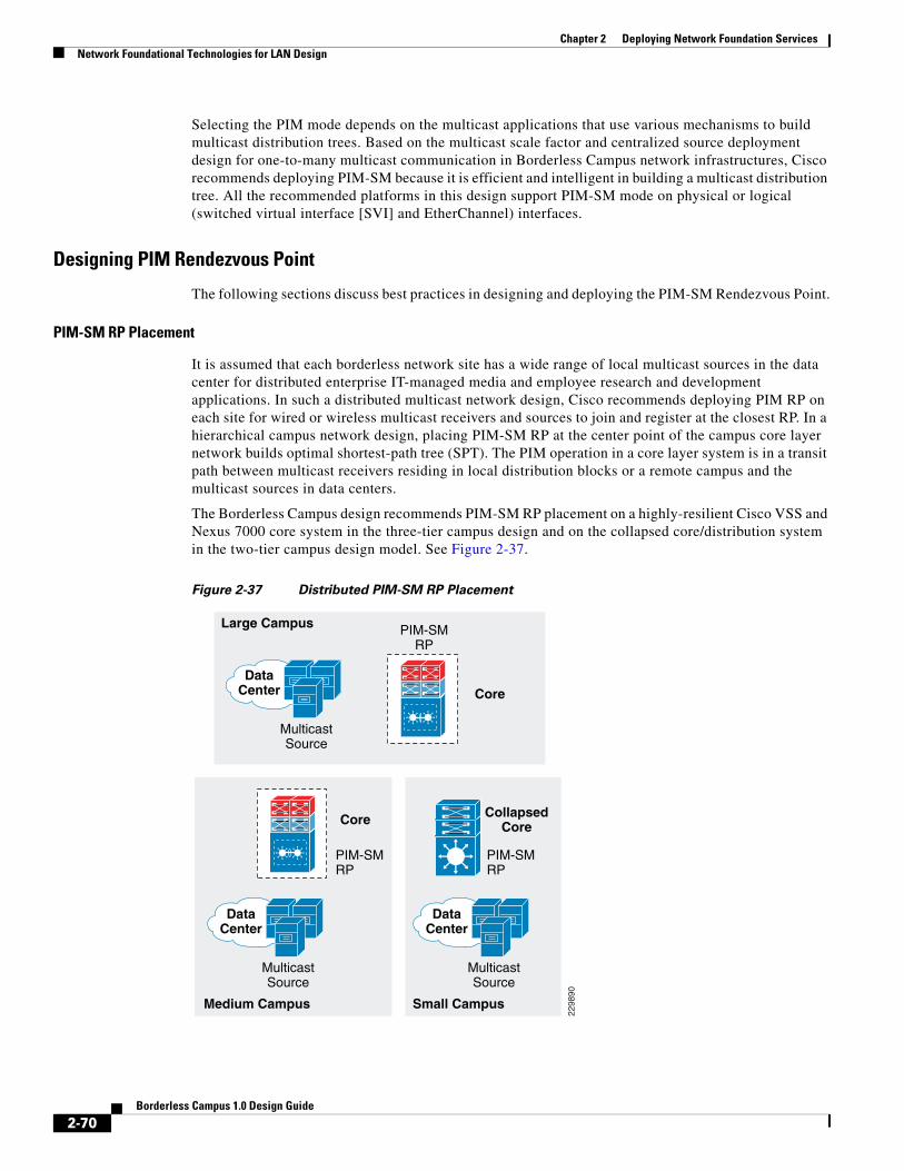
Chapter 2 Deploying Network Foundation ServicesNetwork Foundational Technologies for LAN Design
Selecting the PIM mode depends on the multicast applications that use various mechanisms to build multicast distribution trees. Based on the multicast scale factor and centralized source deployment design for one-to-many multicast communication in Borderless Campus network infrastructures, Cisco recommends deploying PIM-SM because it is efficient and intelligent in building a multicast distribution tree. All the recommended platforms in this design support PIM-SM mode on physical or logical (switched virtual interface [SVI] and EtherChannel) interfaces.
Designing PIM Rendezvous Point
The following sections discuss best practices in designing and deploying the PIM-SM Rendezvous Point.
PIM-SM RP Placement
It is assumed that each borderless network site has a wide range of local multicast sources in the data center for distributed enterprise IT-managed media and employee research and development applications. In such a distributed multicast network design, Cisco recommends deploying PIM RP on each site for wired or wireless multicast receivers and sources to join and register at the closest RP. In a hierarchical campus network design, placing PIM-SM RP at the center point of the campus core layer network builds optimal shortest-path tree (SPT). The PIM operation in a core layer system is in a transit path between multicast receivers residing in local distribution blocks or a remote campus and the multicast sources in data centers.
The Borderless Campus design recommends PIM-SM RP placement on a highly-resilient Cisco VSS and Nexus 7000 core system in the three-tier campus design and on the collapsed core/distribution system in the two-tier campus design model. See Figure 2-37.
Figure 2-37 Distributed PIM-SM RP Placement
2298
90
Large Campus
Core
PIM-SMRP
PIM-SMRP
MulticastSource
DataCenter
Medium Campus Small Campus
MulticastSource
DataCenter
PIM-SMRP
MulticastSource
DataCenter
VSL
Core CollapsedCore
2-70Borderless Campus 1.0 Design Guide

Chapter 2 Deploying Network Foundation ServicesNetwork Foundational Technologies for LAN Design
PIM-SM RP Mode
PIM-SM supports RP deployment in the following three modes in the network:
• Static—In this mode, RP must be statically identified and configured on each PIM router in the network. RP load balancing and redundancy can be achieved using anycast RP.
• Auto-RP—This mode is a dynamic method for discovering and announcing the RP in the network. Auto-RP implementation is beneficial when there are multiple RPs and groups that often change in the network. To prevent network reconfiguration during a change, the RP mapping agent router must be designated in the network to receive RP group announcements and to arbitrate conflicts, as part of the PIM version 1 specification.
• BootStrap Router (BSR)—This mode performs the same tasks as Auto-RP but in a different way and is part of the PIM version 2 specification. Auto-RP and BSR cannot co-exist or interoperate in the same network.
In a small- to mid-sized multicast network, static RP configuration is recommended over the other modes. Static RP implementation offers RP redundancy and load sharing and an additional simple access control list (ACL) can be applied to deploy RP without compromising multicast network security. Cisco recommends designing the enterprise campus multicast network using the static PIM-SM mode configuration and MSDP-based Anycast RP to provide RP redundancy in the campus network. See Figure 2-38.
Figure 2-38 PIM-SM Network Design in Enterprise Network
2905
87
Distribution
Access
Core
Data Center/Services Block/Edge
Large Campus Large Campus
Data Center
QFP
PSTNWAN
Data Center
QFP
PSTNWAN
2-71Borderless Campus 1.0 Design Guide

Chapter 2 Deploying Network Foundation ServicesNetwork Foundational Technologies for LAN Design
Defining the static role of PIM-SM RP at the campus core simplifies the multicast shortest-path tree (SPT) and RP trees (RPT) development operation before data forwarding begins. Based on an ECMP versus an EtherChannel campus network design, the PIM may not build the optimal forwarding shared-tree to utilize all downstream paths to transmit multicast traffic. This is primarily how the multicast distributed tree gets developed in a full mesh and equal-cost parallel paths are deployed in enterprise campus network environments. Deploying Cisco VSS in the distribution layer simplifies and optimizes the unicast and multicast forwarding planes in the campus distribution access block. With a single unified VSS control plane, it eliminates FHRP for gateway redundancy and represents a single PIM DR on a VLAN. The result of a PIM join request from a distribution layer system to a core layer PIM RP depends on the implemented Layer 3 network design—ECMP versus EtherChannel.
ECMP
Multicast forwarding is a connection-oriented process in the campus network. Multicast sources get registered with the local first-hop PIM-SM router and the multicast receivers dynamically join the PIM DR, which is the last-hop router that is rooted towards PIM RP. Following the ECMP unicast routing table, the last-hop PIM routers send PIM join messages to RP through a single Layer 3 interface. This is determined based on the highest next-hop IP address in the RIB table. The multicast distribution tree in the multicast routing table gets developed based on the interface where the PIM join communication occurred. Upon link failure, the alternate Layer 3 interface with the highest next-hop IP address is dynamically selected for multicast traffic. An ECMP-based campus network design may not build an optimal multicast forwarding network topology as it cannot leverage all physical paths available to switch data traffic.
2-72Borderless Campus 1.0 Design Guide
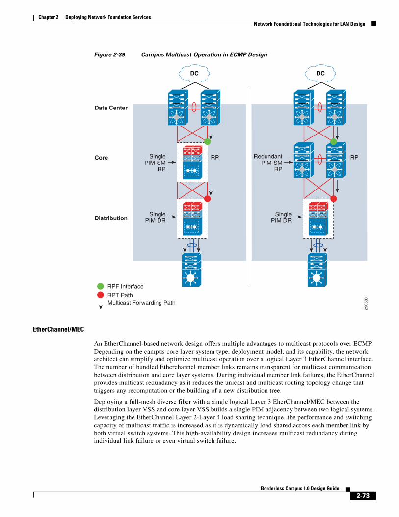
Chapter 2 Deploying Network Foundation ServicesNetwork Foundational Technologies for LAN Design
Figure 2-39 Campus Multicast Operation in ECMP Design
EtherChannel/MEC
An EtherChannel-based network design offers multiple advantages to multicast protocols over ECMP. Depending on the campus core layer system type, deployment model, and its capability, the network architect can simplify and optimize multicast operation over a logical Layer 3 EtherChannel interface. The number of bundled Etherchannel member links remains transparent for multicast communication between distribution and core layer systems. During individual member link failures, the EtherChannel provides multicast redundancy as it reduces the unicast and multicast routing topology change that triggers any recomputation or the building of a new distribution tree.
Deploying a full-mesh diverse fiber with a single logical Layer 3 EherChannel/MEC between the distribution layer VSS and core layer VSS builds a single PIM adjacency between two logical systems. Leveraging the EtherChannel Layer 2-Layer 4 load sharing technique, the performance and switching capacity of multicast traffic is increased as it is dynamically load shared across each member link by both virtual switch systems. This high-availability design increases multicast redundancy during individual link failure or even virtual switch failure.
DC DC
2905
88
Distribution
Core
Data Center
SinglePIM-SM
RP
SinglePIM DR
RedundantPIM-SM
RP
RPRP
SinglePIM DR
RPF Interface
RPT Path Multicast Forwarding Path
2-73Borderless Campus 1.0 Design Guide
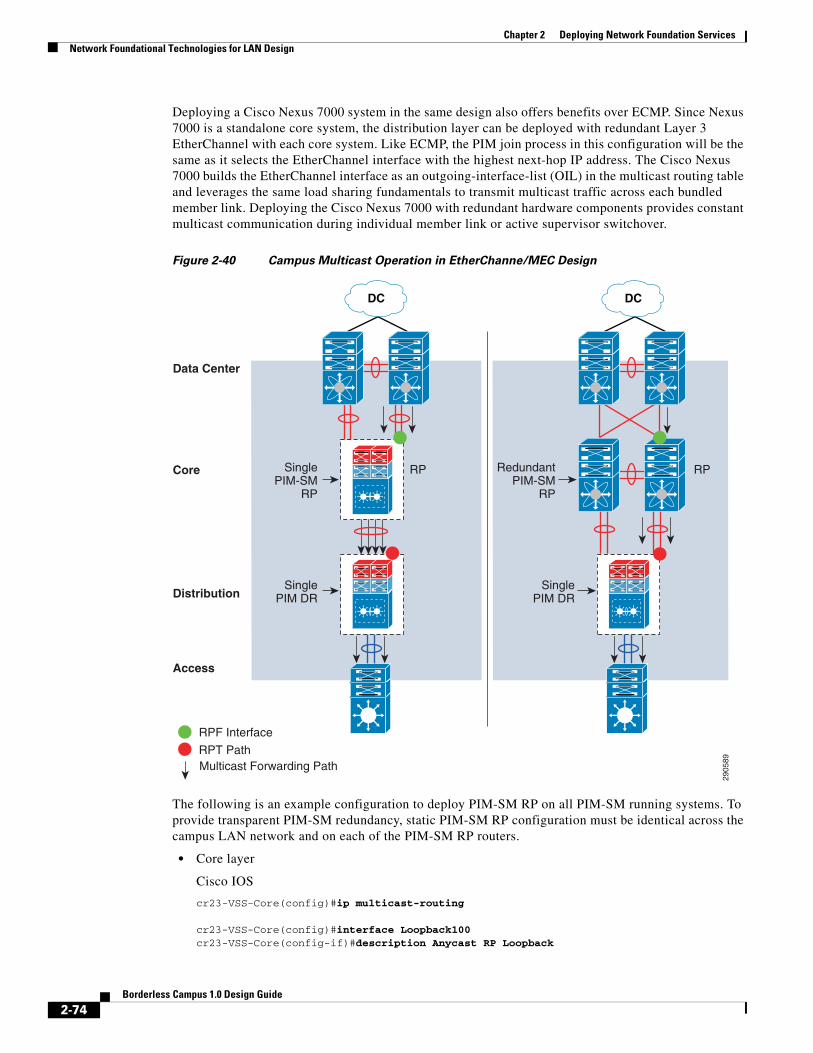
Chapter 2 Deploying Network Foundation ServicesNetwork Foundational Technologies for LAN Design
Deploying a Cisco Nexus 7000 system in the same design also offers benefits over ECMP. Since Nexus 7000 is a standalone core system, the distribution layer can be deployed with redundant Layer 3 EtherChannel with each core system. Like ECMP, the PIM join process in this configuration will be the same as it selects the EtherChannel interface with the highest next-hop IP address. The Cisco Nexus 7000 builds the EtherChannel interface as an outgoing-interface-list (OIL) in the multicast routing table and leverages the same load sharing fundamentals to transmit multicast traffic across each bundled member link. Deploying the Cisco Nexus 7000 with redundant hardware components provides constant multicast communication during individual member link or active supervisor switchover.
Figure 2-40 Campus Multicast Operation in EtherChanne/MEC Design
The following is an example configuration to deploy PIM-SM RP on all PIM-SM running systems. To provide transparent PIM-SM redundancy, static PIM-SM RP configuration must be identical across the campus LAN network and on each of the PIM-SM RP routers.
• Core layer
Cisco IOS
cr23-VSS-Core(config)#ip multicast-routing
cr23-VSS-Core(config)#interface Loopback100cr23-VSS-Core(config-if)#description Anycast RP Loopback
DC DC
2905
89
Distribution
Access
Core
Data Center
SinglePIM-SM
RP
SinglePIM DR
RedundantPIM-SM
RP
RPRP
SinglePIM DR
RPF Interface
RPT Path Multicast Forwarding Path
2-74Borderless Campus 1.0 Design Guide

Chapter 2 Deploying Network Foundation ServicesNetwork Foundational Technologies for LAN Design
cr23-VSS-Core(config-if)#ip address 10.100.100.100 255.255.255.255
cr23-VSS-Core(config)#ip pim rp-address 10.100.100.100
cr23-VSS-Core#show ip pim rp
Group: 239.192.51.1, RP: 10.100.100.100, next RP-reachable in 00:00:34Group: 239.192.51.2, RP: 10.100.100.100, next RP-reachable in 00:00:34Group: 239.192.51.3, RP: 10.100.100.100, next RP-reachable in 00:00:34
cr23-VSS-Core#show ip pim interface
Address Interface Ver/ Nbr Query DR DR Mode Count Intvl Prior10.125.0.12 Port-channel101 v2/S 1 30 1 10.125.0.1310.125.0.14 Port-channel102 v2/S 1 30 1 10.125.0.15…
cr23-VSS-Core#show ip mroute sparse(*, 239.192.51.8), 3d22h/00:03:20, RP 10.100.100.100, flags: S Incoming interface: Null, RPF nbr 0.0.0.0 Outgoing interface list: Port-channel105, Forward/Sparse, 00:16:54/00:02:54 Port-channel101, Forward/Sparse, 00:16:56/00:03:20
(10.125.31.147, 239.192.51.8), 00:16:54/00:02:35, flags: A Incoming interface: Port-channel105, RPF nbr 10.125.0.21 Outgoing interface list: Port-channel101, Forward/Sparse, 00:16:54/00:03:20
cr23-VSS-Core#show ip mroute activeActive IP Multicast Sources - sending >= 4 kbps
Group: 239.192.51.1, (?) Source: 10.125.31.153 (?) Rate: 2500 pps/4240 kbps(1sec), 4239 kbps(last 30 secs), 12 kbps(life avg)
Cisco NX-OS
cr35-N7K-Core1(config)#feature pim!Enable PIM feature set
cr35-N7K-Core1(config)#interface Loopback 0, 100cr35-N7K-Core1(config-if-range)#ip pim sparse-mode!Enable PIM-SM mode on each Loopback interface
cr23-VSS-Core(config)#interface Loopback254cr23-VSS-Core(config-if)#description Anycast RP Loopbackcr23-VSS-Core(config-if)#ip address 10.100.100.100 255.255.255.255
cr35-N7K-Core1(config)#interface Ethernet 1/1 - 8 , Ethernet 2/1 - 8cr35-N7K-Core1(config-if-range)#ip pim sparse-mode!Enable PIM-SM mode on each Layer 3 interface
cr35-N7K-Core1(config)#interface Port-Channel 101 - 103cr35-N7K-Core1(config-if-range)# ip pim sparse-mode
cr35-N7K-Core1(config)#ip pim rp-address 10.100.100.100
cr35-N7K-Core1#show ip pim interface briefPIM Interface Status for VRF "default"
2-75Borderless Campus 1.0 Design Guide

Chapter 2 Deploying Network Foundation ServicesNetwork Foundational Technologies for LAN Design
Interface IP Address PIM DR Address Neighbor Border Count InterfaceEthernet1/1 10.125.20.0 10.125.20.1 1 noEthernet1/2 10.125.10.1 10.125.10.1 1 noport-channel101 10.125.10.1 10.125.10.1 1 noport-channel102 10.125.12.1 10.125.12.1 1 no
cr35-N7K-Core1# show ip mrouteIP Multicast Routing Table for VRF "default"
(*, 239.192.101.1/32), uptime: 00:01:18, pim ip Incoming interface: loopback254, RPF nbr: 10.125.254.254 Outgoing interface list: (count: 2) port-channel101, uptime: 00:01:17, pim port-channel103, uptime: 00:01:18, pim
(10.100.1.9/32, 239.192.101.1/32), uptime: 2d13h, pim ip Incoming interface: Ethernet2/1, RPF nbr: 10.125.20.3, internal Outgoing interface list: (count: 2) port-channel101, uptime: 00:01:17, pim port-channel103, uptime: 00:01:18, pim<snip>
• Distribution layer
cr22-6500-LB(config)#ip multicast-routingcr22-6500-LB(config)#ip pim rp-address 10.100.100.100
cr22-6500-LB(config)#interface range Port-channel 100 – 103cr22-6500-LB(config-if-range)#ip pim sparse-mode
cr22-6500-LB(config)#interface range Vlan 101 – 120cr22-6500-LB(config-if-range)#ip pim sparse-mode
cr22-6500-LB#show ip pim rpGroup: 239.192.51.1, RP: 10.100.100.100, uptime 00:10:42, expires neverGroup: 239.192.51.2, RP: 10.100.100.100, uptime 00:10:42, expires neverGroup: 239.192.51.3, RP: 10.100.100.100, uptime 00:10:41, expires neverGroup: 224.0.1.40, RP: 10.100.100.100, uptime 3d22h, expires never
cr22-6500-LB#show ip pim interface
Address Interface Ver/ Nbr QueryDR DR Mode Count IntvlPrior10.125.0.13Port-channel100v2/S 1 30 1 10.125.0.1310.125.0.0Port-channel101v2/S 1 30 1 10.125.0.1…10.125.103.129Vlan101v2/S 0 30 1 10.125.103.129…
cr22-6500-LB#show ip mroute sparse(*, 239.192.51.1), 00:14:23/00:03:21, RP 10.100.100.100, flags: SC Incoming interface: Port-channel100, RPF nbr 10.125.0.12, RPF-MFD Outgoing interface list: Port-channel102, Forward/Sparse, 00:13:27/00:03:06, H Vlan120, Forward/Sparse, 00:14:02/00:02:13, H Port-channel101, Forward/Sparse, 00:14:20/00:02:55, H Port-channel103, Forward/Sparse, 00:14:23/00:03:10, H Vlan110, Forward/Sparse, 00:14:23/00:02:17, H
cr22-6500-LB#show ip mroute activeActive IP Multicast Sources - sending >= 4 kbps
2-76Borderless Campus 1.0 Design Guide

Chapter 2 Deploying Network Foundation ServicesNetwork Foundational Technologies for LAN Design
Group: 239.192.51.1, (?) RP-tree: Rate: 2500 pps/4240 kbps(1sec), 4240 kbps(last 10 secs), 4011 kbps(life avg)
• Access layer
cr23-3560-LB(config)#ip multicast-routing distributedcr23-3560-LB(config)#ip pim rp-address 10.100.100.100
cr23-3560-LB(config)#interface range Vlan 101 – 110cr22-3560-LB(config-if-range)#ip pim sparse-mode
cr22-3560-LB#show ip pim rpGroup: 239.192.51.1, RP: 10.100.100.100, uptime 00:01:36, expires neverGroup: 239.192.51.2, RP: 10.100.100.100, uptime 00:01:36, expires neverGroup: 239.192.51.3, RP: 10.100.100.100, uptime 00:01:36, expires neverGroup: 224.0.1.40, RP: 10.100.100.100, uptime 5w5d, expires nevercr22-3560-LB#show ip pim interface
Address Interface Ver/ Nbr Query DR DR Mode Count Intvl Prior10.125.0.5 Port-channel1 v2/S 1 30 1 10.125.0.510.125.101.1 Vlan101 v2/S 0 30 1 0.0.0.0…10.125.103.65 Vlan110 v2/S 0 30 1 10.125.103.65
cr22-3560-LB#show ip mroute sparse (*, 239.192.51.1), 00:06:06/00:02:59, RP 10.100.100.100, flags: SC Incoming interface: Port-channel1, RPF nbr 10.125.0.4 Outgoing interface list: Vlan101, Forward/Sparse, 00:06:08/00:02:09 Vlan110, Forward/Sparse, 00:06:06/00:02:05
• WAN edge layer
cr11-asr-we(config)#ip multicast-routing distributed
cr11-asr-we(config)#ip pim rp-address 10.100.100.100
cr11-asr-we(config)#interface range Port-channel1 , Gig0/2/0 , Gig0/2/1.102cr11-asr-we(config-if-range)#ip pim sparse-modecr11-asr-we(config)#interface Ser0/3/0cr11-asr-we(config-if)#ip pim sparse-mode
cr11-asr-we#show ip pim rpGroup: 239.192.57.1, RP: 10.100.100.100, uptime 00:23:16, expires neverGroup: 239.192.57.2, RP: 10.100.100.100, uptime 00:23:16, expires neverGroup: 239.192.57.3, RP: 10.100.100.100, uptime 00:23:16, expires never
cr11-asr-we#show ip mroute sparse
(*, 239.192.57.1), 00:24:08/stopped, RP 10.100.100.100, flags: SP Incoming interface: Port-channel1, RPF nbr 10.125.0.22 Outgoing interface list: Null
(10.125.31.156, 239.192.57.1), 00:24:08/00:03:07, flags: T Incoming interface: Port-channel1, RPF nbr 10.125.0.22 Outgoing interface list: Serial0/3/0, Forward/Sparse, 00:24:08/00:02:55
cr11-asr-we#show ip mroute active
2-77Borderless Campus 1.0 Design Guide
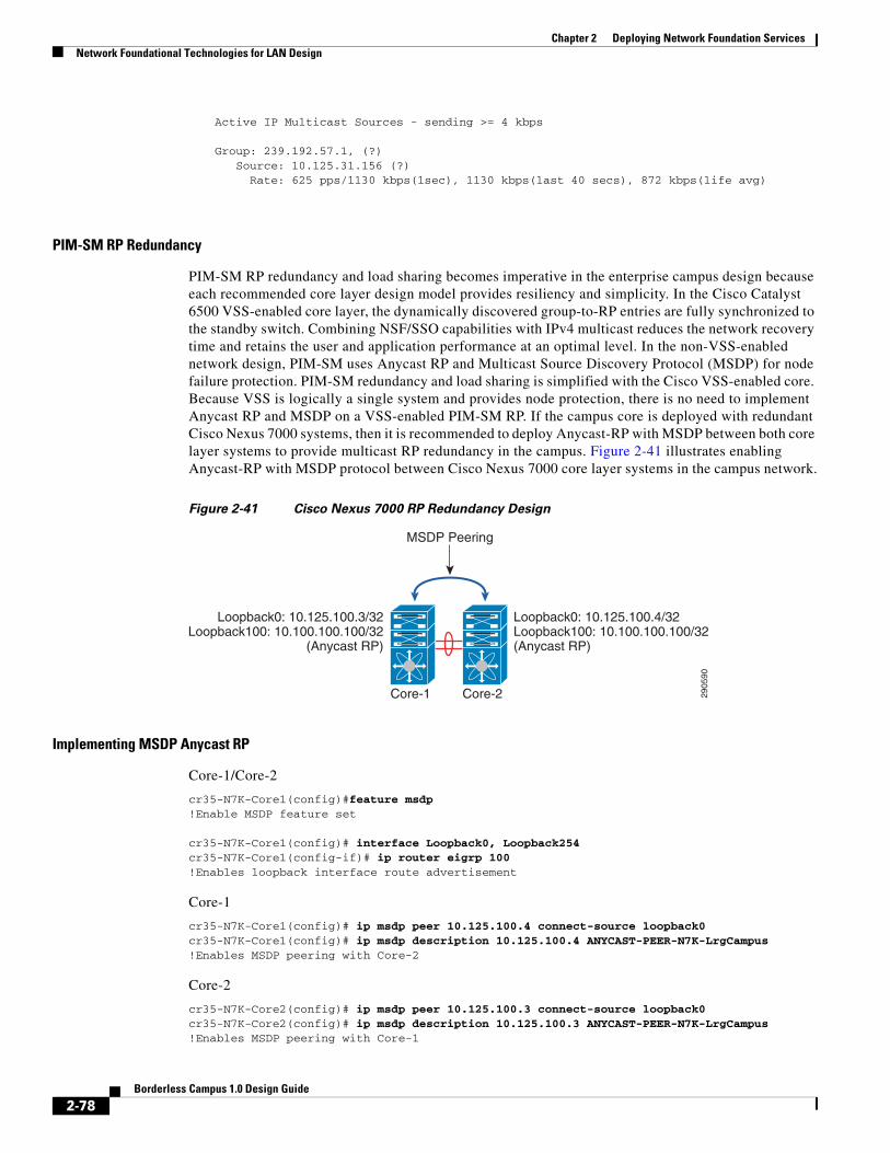
Chapter 2 Deploying Network Foundation ServicesNetwork Foundational Technologies for LAN Design
Active IP Multicast Sources - sending >= 4 kbps
Group: 239.192.57.1, (?) Source: 10.125.31.156 (?) Rate: 625 pps/1130 kbps(1sec), 1130 kbps(last 40 secs), 872 kbps(life avg)
PIM-SM RP Redundancy
PIM-SM RP redundancy and load sharing becomes imperative in the enterprise campus design because each recommended core layer design model provides resiliency and simplicity. In the Cisco Catalyst 6500 VSS-enabled core layer, the dynamically discovered group-to-RP entries are fully synchronized to the standby switch. Combining NSF/SSO capabilities with IPv4 multicast reduces the network recovery time and retains the user and application performance at an optimal level. In the non-VSS-enabled network design, PIM-SM uses Anycast RP and Multicast Source Discovery Protocol (MSDP) for node failure protection. PIM-SM redundancy and load sharing is simplified with the Cisco VSS-enabled core. Because VSS is logically a single system and provides node protection, there is no need to implement Anycast RP and MSDP on a VSS-enabled PIM-SM RP. If the campus core is deployed with redundant Cisco Nexus 7000 systems, then it is recommended to deploy Anycast-RP with MSDP between both core layer systems to provide multicast RP redundancy in the campus. Figure 2-41 illustrates enabling Anycast-RP with MSDP protocol between Cisco Nexus 7000 core layer systems in the campus network.
Figure 2-41 Cisco Nexus 7000 RP Redundancy Design
Implementing MSDP Anycast RP
Core-1/Core-2
cr35-N7K-Core1(config)#feature msdp!Enable MSDP feature set
cr35-N7K-Core1(config)# interface Loopback0, Loopback254cr35-N7K-Core1(config-if)# ip router eigrp 100!Enables loopback interface route advertisement
Core-1
cr35-N7K-Core1(config)# ip msdp peer 10.125.100.4 connect-source loopback0cr35-N7K-Core1(config)# ip msdp description 10.125.100.4 ANYCAST-PEER-N7K-LrgCampus!Enables MSDP peering with Core-2
Core-2
cr35-N7K-Core2(config)# ip msdp peer 10.125.100.3 connect-source loopback0cr35-N7K-Core2(config)# ip msdp description 10.125.100.3 ANYCAST-PEER-N7K-LrgCampus!Enables MSDP peering with Core-1
2905
90Core-1 Core-2
MSDP Peering
Loopback0: 10.125.100.4/32Loopback100: 10.100.100.100/32(Anycast RP)
Loopback0: 10.125.100.3/32Loopback100: 10.100.100.100/32
(Anycast RP)
2-78Borderless Campus 1.0 Design Guide

Chapter 2 Deploying Network Foundation ServicesNetwork Foundational Technologies for LAN Design
cr35-N7K-Core1# show ip msdp peer 10.125.100.4 | inc "peer|local|status"MSDP peer 10.125.100.4 for VRF "default"AS 0, local address: 10.125.100.3 (loopback0) Connection status: Established
cr35-N7K-Core2# show ip msdp peer 10.125.100.3 | inc "peer|local|status"MSDP peer 10.125.100.3 for VRF "default"AS 0, local address: 10.125.100.4 (loopback0) Connection status: Established
Inter-Site PIM Anycast RP
MSDP allows PIM RPs to share information about the active sources. PIM-SM RPs discover local receivers through PIM join messages, while the multicast source can be in a local or remote network domain. MSDP allows each multicast domain to maintain an independent RP that does not rely on other multicast domains, but does enable RPs to forward traffic between domains. PIM-SM is used to forward the traffic between the multicast domains.
Anycast RP is a useful application of MSDP. Originally developed for inter-domain multicast applications, MSDP used with Anycast RP is an intra-domain feature that provides redundancy and load sharing capabilities. Large networks typically use Anycast RP for configuring a PIM-SM network to meet fault tolerance requirements within a single multicast domain.
The enterprise campus multicast network must be designed with Anycast RP. PIM-SM RP at the main or the centralized core must establish an MSDP session with RP on each remote site to exchange distributed multicast source information and allow RPs to join SPT to active sources as needed. Figure 2-42 shows an example of an enterprise campus multicast network design.
2-79Borderless Campus 1.0 Design Guide

Chapter 2 Deploying Network Foundation ServicesNetwork Foundational Technologies for LAN Design
Figure 2-42 Inter-Site Multicast Network Design
Implementing Inter-Site MSDP Anycast RP
Large Campus
cr23-VSS-Core(config)#ip msdp peer 10.122.200.2 connect-source Loopback0cr23-VSS-Core(config)#ip msdp description 10.122.200.2 ANYCAST-PEER-6k-RemoteLrgCampuscr23-VSS-Core(config)#ip msdp peer 10.124.200.2 connect-source Loopback0cr23-VSS-Core(config)#ip msdp description 10.124.200.2 ANYCAST-PEER-4k-RemoteSmlCampuscr23-VSS-Core(config)#ip msdp cache-sa-statecr23-VSS-Core(config)#ip msdp originator-id Loopback0
cr23-VSS-Core#show ip msdp peer | inc MSDP Peer|StateMSDP Peer 10.122.200.2 (?), AS ? State: Up, Resets: 0, Connection source: Loopback0 (10.125.200.254)MSDP Peer 10.123.200.1 (?), AS ? State: Up, Resets: 0, Connection source: Loopback0 (10.125.200.254)MSDP Peer 10.124.200.2 (?), AS ? State: Up, Resets: 0, Connection source: Loopback0 (10.125.200.254)
Medium Campuscr14-6500-RLC(config)#ip msdp peer 10.125.200.254 connect-source Loopback0cr14-6500-RLC(config)#ip msdp description 10.125.200.254 ANYCAST-PEER-6k-MainCampuscr14-6500-RLC(config)#ip msdp cache-sa-statecr14-6500-RLC(config)#ip msdp originator-id Loopback0
cr14-6500-RLC#show ip msdp peer | inc MSDP Peer|State|SAs learned
2298
92
Loopback0 : 10.125.200.254/32Loopback100 : 10.100.100.100/32(Anycast RP)
Loopback0 : 10.124.200.2/32Loopback100 : 10.100.100.100/32(Anycast RP)
Loopback0 : 10.122.200.2/32Loopback100 : 10.100.100.100/32(Anycast RP)
Large Campus
MSDP Peering
Small CampusMedium Campus
PIM-SM RP
PIM-SMAnycast RP
PIM-SM RP
PIM-SM RP
2-80Borderless Campus 1.0 Design Guide

Chapter 2 Deploying Network Foundation ServicesNetwork Foundational Technologies for LAN Design
MSDP Peer 10.125.200.254 (?), AS ?State: Up, Resets: 0, Connection source: Loopback0 (10.122.200.2)SAs learned from this peer: 94
Small Campus
cr14-4507-RSC(config)#ip msdp peer 10.125.200.254 connect-source Loopback0cr14-4507-RSC(config)#ip msdp description 10.125.200.254 ANYCAST-PEER-6k-MainCampuscr14-4507-RSC(config)#ip msdp cache-sa-statecr14-4507-RSC(config)#ip msdp originator-id Loopback0
cr14-4507-RSC#show ip msdp peer | inc MSDP Peer|State|SAs learnedMSDP Peer 10.125.200.254 (?), AS ? State: Up, Resets: 0, Connection source: Loopback0 (10.124.200.2) SAs learned from this peer: 94
Dynamic Group Membership
Multicast receiver registration is done via IGMP protocol signaling. IGMP is an integrated component of an IP multicast framework that allows the receiver hosts and transmitting sources to be dynamically added to and removed from the network. Without IGMP, the network is forced to flood rather than multicast the transmissions for each group. IGMP operates between a multicast receiver host in the access layer and the Layer 3 router at the distribution layer.
The multicast system role changes when the access layer is deployed in the multilayer and routed access models. Because multilayer access switches do not run PIM, it becomes complex to make forwarding decisions out of the receiver port. In such a situation, Layer 2 access switches flood the traffic on all ports. This multilayer limitation in access switches is solved by using the IGMP snooping feature, which is enabled by default and is recommended to not be disabled.
IGMP is still required when a Layer 3 access layer switch is deployed in the routed access network design. Because the Layer 3 boundary is pushed down to the access layer, IGMP communication is limited between a receiver host and the Layer 3 access switch. In addition to the unicast routing protocol, PIM-SM must be enabled at the Layer 3 access switch to communicate with RPs in the network.
Implementing IGMP
By default, the Layer 2 access switch dynamically detects IGMP hosts and multicast-capable Layer 3 PIM routers in the network. The IGMP snooping and multicast router detection functions on a per-VLAN basis and is globally enabled by default for all the VLANs.
The multicast routing function changes when the access switch is deployed in routed access mode. PIM operation is performed at the access layer; therefore, the multicast router detection process is eliminated. The following output from a Layer 3 switch verifies that the local multicast ports are in router mode and provide a snooped Layer 2 uplink port channel which is connected to the collapsed core router for multicast routing:
The IGMP configuration can be validated using the following show command on the Layer 2 and Layer 3 access switch:
Layer 2 Accesscr22-3750-LB#show ip igmp snooping groupsVlan Group Type Version Port List-----------------------------------------------------------------------110 239.192.51.1 igmp v2 Gi1/0/20, Po1
2-81Borderless Campus 1.0 Design Guide
Chapter 2 Deploying Network Foundation ServicesNetwork Foundational Technologies for LAN Design
110 239.192.51.2 igmp v2 Gi1/0/20, Po1110 239.192.51.3 igmp v2 Gi1/0/20, Po1
cr22-3750-LB#show ip igmp snooping mrouterVlan ports------- -------110 Po1(dynamic)
Layer 3 Accesscr22-3560-LB#show ip igmp membership Channel/Group Reporter Uptime Exp. Flags Interface *,239.192.51.1 10.125.103.106 00:52:36 02:09 2A Vl110 *,239.192.51.2 10.125.103.107 00:52:36 02:12 2A Vl110 *,239.192.51.3 10.125.103.109 00:52:35 02:16 2A Vl110 *,224.0.1.40 10.125.0.4 3d22h 02:04 2A Po1 *,224.0.1.40 10.125.101.129 4w4d 02:33 2LA Vl103
cr22-3560-LB#show ip igmp snooping mrouterVlan ports------- ------ 103 Router 106 Router 110 Router
Designing Multicast Security
When designing multicast security in the borderless enterprise campus network design, two key concerns are preventing a rogue source and preventing a rogue PIM-RP.
Preventing Rogue Source
In a PIM-SM network, an unwanted traffic source can be controlled with the pim accept-register command. When the source traffic hits the first-hop router, the first-hop router (DR) creates the (S,G) state and sends a PIM source register message to the RP. If the source is not listed in the accept-register filter list (configured on the RP), the RP rejects the register and sends back an immediate Register-Stop message to the DR. The drawback with this method of source filtering is that with the pim accept-register command on the RP, the PIM-SM (S,G) state is still created on the first-hop router of the source. This can result in traffic reaching receivers local to the source and located between the source and the RP. Furthermore, because the pim accept-register command works on the control plane of the RP, this can be used to overload the RP with fake register messages and possibly cause a DoS condition.
The following is the sample configuration with a simple ACL that has been applied to the RP to filter only on the source address. It is also possible to filter the source and the group using an extended ACL on the RP:
Cisco IOS
cr23-VSS-Core(config)#ip access-list extended PERMIT-SOURCEScr23-VSS-Core(config-ext-nacl)# permit ip 10.120.31.0 0.7.0.255 239.192.0.0 0.0.255.255cr23-VSS-Core(config-ext-nacl)# deny ip any any
cr23-VSS-Core(config)#ip pim accept-register list PERMIT-SOURCES
Cisco NX-OS
cr35-N7K-Core1(config)# route-map PERMIT_SOURCES permit 10cr35-N7K-Core1(config-route-map)# match ip multicast source 10.120.31.0/24 group-range 239.192.0.0 to 239.192.255.255
2-82Borderless Campus 1.0 Design Guide
Chapter 2 Deploying Network Foundation ServicesSummary
cr35-N7K-Core1(config)#ip pim register-policy PERMIT_SOURCES
Preventing Rogue PIM-RP
Like the multicast source, any router can be misconfigured or can maliciously advertise itself as a multicast RP in the network with the valid multicast group address. With a static RP configuration, each PIM-enabled router in the network can be configured to use static RP for the multicast source and override any other Auto-RP or BSR multicast router announcement from the network.
The following is the sample configuration that must be applied to each PIM-enabled router in the campus network to accept PIM announcements only from the static RP and ignore dynamic multicast group announcement from any other RP:
Cisco IOS
cr23-VSS-Core(config)#ip access-list standard Allowed_MCAST_Groupscr23-VSS-Core(config-std-nacl)# permit 224.0.1.39cr23-VSS-Core(config-std-nacl)# permit 224.0.1.40cr23-VSS-Core(config-std-nacl)# permit 239.192.0.0 0.0.255.255cr23-VSS-Core(config-std-nacl)# deny any
cr23-VSS-Core(config)#ip pim rp-address 10.100.100.100 Allowed_MCAST_Groups override
Cisco NX-OS
cr35-N7K-Core1(config)# route-map Allowed_MCAST_Groups permit 10cr35-N7K-Core1(config-route-map)# match ip address Allowed_MCAST_Groups cr35-N7K-Core1(config-route-map)# match ip multicast group 224.0.1.39/32 cr35-N7K-Core1(config-route-map)# route-map Allowed_MCAST_Groups permit 20cr35-N7K-Core1(config-route-map)# match ip multicast group 224.0.1.40/32 cr35-N7K-Core1(config-route-map)# route-map Allowed_MCAST_Groups permit 30cr35-N7K-Core1(config-route-map)# match ip multicast group 239.192.0.0/16
cr35-N7K-Core1(config)# ip pim rp-address 10.100.100.100 route-map Allowed_MCAST_Groups override
Designing the LAN network for the enterprise network design establishes the foundation for all other aspects within the service fabric (WAN, security, mobility, and UC) as well as laying the foundation to provide safety and security, operational efficiencies, etc.
SummaryThis Borderless Campus 1.0 chapter focuses on designing campus hierarchical layers and provides design and deployment guidance. Network architects should leverage Cisco recommended best practices to deploy key network foundation services such as routing, switching, QoS, multicast, and high availability. Best practices are provided for the entire enterprise design.
2-83Borderless Campus 1.0 Design Guide

Chapter 2 Deploying Network Foundation ServicesSummary
2-84Borderless Campus 1.0 Design Guide