vshield app design guide - vmware.com · deployment of security around the virtualized server...
TRANSCRIPT

VMware® vShield App Design GuideT E C H N I C A L W H I T E P A P E R

T E C H N I C A L W H I T E P A P E R / 2
VMware vShield App Design Guide
OverviewVMware® vShield App is one of the security products in the VMware vShield family that provides protection to applications or resource pools in a virtual datacenter from internal as well as external network-based threats. The virtual datacenter (vDC) is a new virtual infrastructure deployment concept that allows IT to provide on-demand infrastructure services to its customers on a common shared infrastructure while maintaining isolation, security, and flexibility of resources. This document helps VI administrators understand the deployment of security around the virtualized server infrastructure using the VMware vShield App product. First, a brief history on the evolution of the datacenter from siloed physical infrastructure (physical datacenter) to virtualized/consolidated infrastructure is provided, and is followed by a discussion on security design practices used by companies to protect their assets. Finally, two reference designs are provided to help customers understand the security deployment around the virtual infrastructure using the vShield App product and the advantages of these designs.
In the late 1990s, IT deployed separate physical infrastructures, also called enclaves, for separate applications. Each enclave included its own set of server, storage and network infrastructures. This IT infrastructure was highly overprovisioned to handle worst-case loads and was underutilized most of the time. After VMware introduced x86 server virtualization technology in early 2000, IT started implementing server virtualization to achieve the benefits of consolidation and improved utilization. With server virtualization, multiple applications started running on a single physical server taking advantage of high-end multicore processors’ processing power. This server consolidation has created challenges for IT administrators in terms of security, and how to provide isolation for different applications while utilizing the same physical infrastructure.
Let us look at the traditional security design approaches used to secure the IT infrastructure.
Air Gap
Mixed-Trust Zonewith Network Silo
Mixed-Trust Zonewith VLAN
Mixed-Trust Zone with Virtual Enclaves
VM
VM
VM
Legend
HR App
FIN App
SALES App
vShield App–Based Security
VM
VM
VM
VM
VM
VM
HR App FIN App Sales App
Cluster 1
VMware vSphere + vShieldAccess
Aggregation
Core
vSphere
VMVMVM
vSphere
Core
Aggregation
Access
VM VMVM
Access
Aggregation
vSphere vSphere vSphere
Core
VM VM VM VM VM VM
Figure 1. Continuum.

T E C H N I C A L W H I T E P A P E R / 3
VMware vShield App Design Guide
Over the years, network and security administrators have provided security to the IT infrastructure by segmenting networks physically, or logically through VLANs, and by introducing different security devices inline to control traffic flow. Figure 1 shows the continuum in terms of how security deployments have evolved over the years from the air gap approach, in which separation was provided through physical silos, to a complex mixed-trust zone with VLAN approach, in which logical separation is achieved through complex network and security configurations. These approaches restrict the cloud deployment, as the rigid physical infrastructure limits the flexibility of moving resources on demand and also doesn’t provide visibility and control over the virtual infrastructure (virtual machine–to–virtual machine traffic on a host). A mixed-trust zone with virtual enclaves built using vShield App provides the solution to the problems faced by the traditional security deployments. Table 1 compares different security designs with respect to deployment and management complexity.
PARAMETERS AIR GAP MIXED-TRUST ZONE WITH NETWORK SILO
MIXED-TRUST ZONE WITH VLAN
MIXED-TRUST ZONE WITH VIRTUAL ENCLAVES
RESOURCE UTILIZATION
Underutilized server and network resources; no consolidation
Better utilized server, but underutilized network resources; only server consolidation
Better utilized server and network resources; best consolidation
Better utilized server, network, and security resources; best consolidation
NUMBER OF PHYSICAL DEVICES
High High Medium Low
COMPLEXITY Low Medium High Low
DEPLOYMENT AND MANAGEMENT CHALLENGES
Management of multiple devices
Multiple NICs required on servers (blade servers can’t provide required port density), complexity of managing cabling, management of multiple network and security devices
Complex to configure with VLANs, firewall rule sprawl, firewall chokepoint, large fault domain
New way of deploying security; very easy to deploy and manage
Table 1. Security Deployment Comparison.

T E C H N I C A L W H I T E P A P E R / 4
VMware vShield App Design Guide
Security Design and ZonesThe goal of security design in any company is to meet the business need of protecting assets while providing access to authorized users. There are different security requirements from different organizations in a company, depending on which regulatory environment they operate in. Security administrators first define security zones for the different assets in an organization based on the risk analysis results. This zoning helps the security administrator to create security policies and mitigation strategies for the respective zones based on their importance. As shown in Figure 2, there are two main categories of zones in any company:
•Perimeter zone, also referred to as DMZ (demilitarized zone): This zone contains assets that are accessible from the public internet.
•Internal zones: These are the zones created internal to the organization to provide isolation from the public as well as internally created different organizational infrastructures.
DMZ/Perimeter Zone
Internet
Core Network
Datacenter
Internal Zone 1(HR App)
Internal Zone 2(FIN App)
Internal Zone 3(SALES App)
Campus Network
Figure 2. Security Zones.
Each zone has its own security requirements depending on what functionality and applications are allowed to run in that zone. In this document, the focus is on how to implement security for internal zones that are created based on which organizations applications are hosted. This document will not discuss the perimeter zone security design (this will be covered in the vShield Edge Design Guide).
Customers/IT can decide to deploy internal zones either to isolate different organizations they are supporting or to isolate different application tiers. Some customer IT has moved to the private cloud model where they act as a service provider to the internal organizations and provide infrastructure as a service (IaaS). These customers need the flexibility in the security infrastructure to implement a private cloud, where resource pools or zones are created and deleted on demand.

T E C H N I C A L W H I T E P A P E R / 5
VMware vShield App Design Guide
Let us look at the security deployment process in virtual infrastructure. IT has established new processes in terms of how it deploys server virtualization. However, the process of deploying security has not evolved to support a virtual infrastructure. The following section discusses how VI administrators build new consolidated infrastructure, and how security is bolted onto this infrastructure using an air gap, mixed-trust zone with network silo, or mixed-trust zone with VLAN approach.
Consolidated Workload and Security As described in the overview section, there are three traditional deployment models that a customer might use to secure a virtual infrastructure:
•Air gap: This is for customers who provide security by deploying a siloed virtual infrastructure for each department or organization. This design for a siloed virtual infrastructure is similar to the traditional design of deploying different physical servers for different applications. The impact of implementing security through a siloed infrastructure is the underutilization of resources. For example, unused resources in one virtual infrastructure can’t be utilized by another virtual infrastructure that needs extra resources. This approach is termed the air gap approach, in which customers introduce network and security devices in the data path to monitor and control the flow of information through security rules, which are configured into these point devices. This deployment is simple to design, but involves higher CAPEX and OPEX.
•Mixed-trust zone with network silo: This design approach will be used by enterprise customers who are concerned about server consolidation ratios and want to utilize physical server resources effectively, but at the same time want to provide physical network isolation. In this approach server consolidation is achieved, but the network and security infrastructure is built separately for each host or cluster.
•Mixed-trust zone with VLAN: Some customers want to take full advantage of consolidation by creating mixed trust zones that are separated by logical networks using VLANs, and by using integrated network and security devices. In this approach the complexity of the deployment grows exponentially as management of security rules become difficult.
Let us look at the above deployment scenarios in detail, and corresponding security and operational challenges that are faced with these approaches. To illustrate, a simple design option is described in which a customer wants to deploy three different applications for three different organizations, along with a description of how each deployment tries to provide isolation and security among these three different applications (HR, Finance and Sales). Each deployment is then evaluated based on the following common criteria:
1) Ability to prevent damage from internal attacks (these are the attacks originated from a VM targeting another virtual machine on the same host)
2) Ability to prevent damage from external attacks (these are the attacks originated by a VM on a host, internal zones, or outside the datacenter)
3) Visibility into infrastructure
4) Dynamic security policies that can move along with the virtual machines (adaptive)
5) Operational simplicity and scalability of the solution (simple and scalable)

T E C H N I C A L W H I T E P A P E R / 6
VMware vShield App Design Guide
Air Gap Security DeploymentAs shown in Figure 3, the customer has deployed three different applications for different organizations (HR, Finance and Sales) on three separate hosts, each with its associated separate storage, network, and security devices. The assumption here is that there are three separate layer 2 domains (or separate VLANs) with access to the devices in the respective domain provided through layer 2 switches. The three applications can communicate with each other only if the firewall rules are configured and the router is configured to allow the traffic flow. This is a complex deployment for a VI administrator to understand, in which the network administrator provides block of IP address space in three separate subnets and a list of ports on which the servers can be connected. The security administrator creates firewall rules for different zones and restricts traffic to and from the zone based on the applications that are deployed in that zone. At the same time load balancers provide the capability to spread the load across the hosts in a cluster. And an Intrusion Prevention System (IPS) monitors the traffic to and from the cluster to detect any anomalies or threats that can impact the hosts. However, the IPS can monitor only traffic that is passing through the host network interface cards and not internal to the host traffic that is flowing through a vSwitch/vDS.
Table 2 provides an evaluation of this design based on the common security criteria.
VM VM VM VM VM VM VM VM VM
Access
Firewall
L2-L3 Switch
HR App FIN App Sales App
Load Balancer
IPSSwitch Switch Switch
IPS IPS
Firewall
L2-L3 Switch
Load Balancer
Firewall
L2-L3 Switch
Load Balancer
Aggregation
vSphere vSphere vSphere
Core
Figure 3. Air Gap.
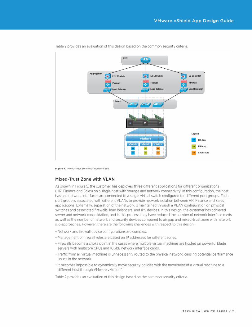
Mixed-Trust Zone with Network SiloAs shown in Figure 4, the customer has deployed three different applications for different organizations (HR, Finance and Sales) on a single host with storage and network connectivity. In this configuration the host has three network interface cards that are connected to three separate virtual switches to provide network isolation for the different applications. Externally, separation of the network is maintained through separate physical switches and associated firewall devices. In this design the customer has achieved the server consolidation by deploying a mixed-trust workload, but the number of network and security devices are the same as in the air gap deployment. An important requirement for this design is higher network interface card density on hosts to provide physical isolation. This design is referred to as mixed-trust because three different applications are running on a single host. The mixed-trust design can also have a single cluster with multiple hosts running multiple applications instead of a single host described in this design.
T E C H N I C A L W H I T E P A P E R / 7
VMware vShield App Design Guide
Table 2 provides an evaluation of this design based on the common security criteria.
VM
VM
VM
VM
VM
VM
vSphere
vSwitch vSwitch vSwitch
Core
Aggregation
Access
VM
VM
VM
Legend
HR App
FIN App
SALES App
L2-L3 Switch
Firewall
Load Balancer
L2-L3 Switch
Firewall
Load Balancer
L2-L3 Switch
Firewall
Load Balancer
Figure 4. Mixed-Trust Zone with Network Silo.
Mixed-Trust Zone with VLANAs shown in Figure 5, the customer has deployed three different applications for different organizations (HR, Finance and Sales) on a single host with storage and network connectivity. In this configuration, the host has one network interface card connected to a single virtual switch configured for different port groups. Each port group is associated with different VLANs to provide network isolation between HR, Finance and Sales applications. Externally, separation of the network is maintained through a VLAN configuration on physical switches and associated firewalls, load balancers, and IPS devices. In this design, the customer has achieved server and network consolidation, and in this process they have reduced the number of network interface cards as well as the number of network and security devices compared to air gap and mixed-trust zone with network silo approaches. However, there are the following challenges with respect to this design:
•Network and firewall device configurations are complex.
•Management of firewall rules are based on IP addresses for different zones.
•Firewalls become a choke point in the cases where multiple virtual machines are hosted on powerful blade servers with multicore CPUs and 10GbE network interface cards.
•Traffic from all virtual machines is unnecessarily routed to the physical network, causing potential performance issues in the network.
•It becomes impossible to dynamically move security policies with the movement of a virtual machine to a different host through VMware vMotion™.
Table 2 provides an evaluation of this design based on the common security criteria.

T E C H N I C A L W H I T E P A P E R / 8
VMware vShield App Design Guide
VM
VM
VM
VM
VM
VM
VMVM
VM
Legend
Access
Firewall
L2-L3 Switch
Load Balancer
IPS
Aggregation
Core
VLAN A
VLAN B
VLAN C
HR App
FIN App
SALES App
vSphere
vSwitch
Figure 5. Mixed-Trust Zone with VLAN.
Design Approach with vShield AppTo overcome the challenges faced by IT administrators in providing a secure virtual infrastructure, a new, simple and adaptive vShield App–based solution is described below. This approach is different from the traditional security approaches and needs strong collaboration between security and VI administrators. Instead of security administrators creating security rules based on the IP parameter groupings, the rules are based on the CPU/memory resources group that the VI administrator creates; they can also be based on user-defined security groups.
During a typical datacenter deployment, security administrators are creating internal zones and associated security policies, while VI administrators are carving out resource pools for different organizations based on the organization needs. In the VMware environment a resource pool (RP) allows users to control the aggregate CPU and memory resources of the compute resource, which is either a standalone host or a VMware Distributed Resource Scheduler (VMware DRS) cluster. There are two different methods for carving out resources:
1) Resource pool (RP) method: This method enables customers to delegate control over resources of a host or cluster. Like a virtual machine, a resource pool has reservation, limit and share values for both CPU and memory resources. Based on customer needs, a resource pool can be organized hierarchically, with a root resource pool providing resources to different organizations (HR, finance and sales) and child resource pools serving different groups in the organizations.
2) vApp method: vApp is a container, like a resource pool, and can contain one or more virtual machines. In addition, a vApp also shares some functionality with a virtual machine. A vApp can power on and power off, and it can also be cloned. These features help in deployment and management of multitier applications where customers need more control over operational policies of each tier and of SLAs associated with it.
Customers use either approach to create resource pools.

T E C H N I C A L W H I T E P A P E R / 9
VMware vShield App Design Guide
As mentioned earlier, security rules or policies for an internal zone are built around IP address groupings where some combination of source and destination IPs are blocked or allowed. However, vShield App provides the capability of creating security rules around groups (cluster, resource pool, vApp) that are available in the VMware environment. For example, grouping could be done at datacenter, cluster, resource-pool, or vApp level, and security rules can be applied to those groups.
An example of such a security rule is described below:
RP1 to RP2 traffic deny: With this rule, no traffic is allowed from resource pool 1 to resource pool 2. There is no need to provide IP addresses while defining the rules, thus simplifying the management of security rules. Also, these rules are inherited by the virtual machines running in that group. So as long as administrators make sure to spawn a virtual machine in the right group, the security policies will be applied to the virtual machine. In cases where a virtual machine gets moved to another host, either because of host failure or because of not enough resources on the host, the security policies also move along with the virtual machine.
In the following sections two design options using vShield App are described, one in which VI administrators use the resource pool method to carve out resources for the organizations, and the second, in which the vApp method is used to carve resources. Details on how security rules developed by security administrators can be applied to the different groupings of resource pools are provided while discussing each design.
The following components of the design are common to both options.
Common ComponentsThe following are the common components in the design. This list doesn’t include the external network and storage infrastructure that is required to build the virtual infrastructure. It is assumed that based on the customer environment there will be an iSCSI or fibre channel (FC) SAN infrastructure and also network switches and router infrastructure.
Hosts Six physical hardware servers provide compute, memory, and network resources based on the configuration of the hardware. It might be, for example, an HP ProLiant DL380 rack-mountable server with two Intel Xeon CPUs (4 core each), 96GB of memory, 2 x 10GbE network interface cards running VMware ESX®/VMware ESXi™. Customers might have different hardware capacity, which will drive the decision regarding how many virtual machines or workloads can be hosted on that particular hardware.
vShield AppvShield App is an interior, vNIC-level firewall that allows users to create access control policies regardless of network topology. A vShield App monitors all traffic in and out of an ESX host, including that between virtual machines in the same port group. vShield App includes traffic analysis and container-based policy creation. One vShield App is deployed per host.
ClusterA cluster is a collection of ESX/ESXi hosts and associated virtual machines with shared resources. When a user adds a host to the VMware DRS cluster, the host’s resources become part of the cluster’s resources. There is one cluster with six hosts in this design.
Number of Internal Zones/TenantsAs described earlier, security administrators create internal zones to create separate security policies for each zone based on the risk to attacks as well as the importance of those resources to the organization. Internal security zones could be based on different organizations such as HR, Finance and Marketing or they could be based on application tiers such as Web, App, and DB tier. Based on the customer needs, any number of zones can be created.

T E C H N I C A L W H I T E P A P E R / 1 0
VMware vShield App Design Guide
In the following design options, three internal security zones are considered that will support three different application tiers (Web, App, and DB). The number of internal zones will be different based on the customer needs and security requirements. These internal zones are referred to as internal zone 1, internal zone 2, and internal zone 3.
Security Rules The following are the security rules defined by the security administrator to protect the zones from each other:
•Internet → internal zone 1: only TCP port 80 traffic allowed•Internal zone 1 → internal zone 2: only TCP port 2222 traffic allowed•Internal zone 1 → internal zone 3: no traffic allowed•Internal zone 2 → internal zone 3: only TCP port 3333 traffic allowed
Design Option 1 (Resource Allocation Based on Resource Pool)This design describes how to provide security around the resource pools created by VI administrators.
Number of Resource PoolsIn this design, there are six hosts in a cluster with a set of CPU and memory resources at the root level. Customers can create child resource pools out of the root or other child resources. This hierarchy of resource pools allows VI administrators to carve out resources for different organizations or applications by specifying reservations, shares and limits for each resource pool.
As mentioned previously, the resource pool method is used in this design option. There are three resource pools, as shown in Figure 6: RP1, RP2 and RP3. These child resource pools are created to provide resources to three different organizations (HR, Finance and Sales).
Mapping of Internal Zones Security Rules to Resource Pools If a VI administrator allocates resources to an internal zone based on the resource pools, then the security rules defined for internal zones can be mapped to respective resource pools (RP1, RP2 and RP3) as follows:
1) Datacenter → RP1: only TCP port 80 traffic allowed
2) RP1 → RP2: only TCP port 2222 traffic allowed
3) RP1 → RP3: no traffic allowed
4) RP2 → RP3: only TCP port 3333 traffic allowed
Security Policies in vShield App The vShield App firewall is a centralized, hierarchical firewall that enables customers to create rules at datacenter, cluster, resource-pool and vApp levels. These different levels are also termed as “containers.” The rules are enforced in the following container hierarchy:
1) Datacenter high-precedence rules
2) Cluster-level rules
3) Datacenter low-precedence rules
4) User-defined security-group rules
5) Default rules

T E C H N I C A L W H I T E P A P E R / 1 1
VMware vShield App Design Guide
vShield App enforces these rules by monitoring in and out of an ESX host, including between virtual machines in the same port group. The rule enforcement is based on the container-level precedence or custom priority precedence. In the case of container-level precedence, the datacenter-level rules have higher priority than the cluster-level rules. When a rule is configured at datacenter level, the rule is inherited by all the clusters and vShield apps therein. Because datacenter high-precedence rules are above cluster-level rules, customers must ensure that cluster-level rules are not in conflict with datacenter high-precedence rules. For more details on custom priority precedence, refer to the vShield Administrator Guide.
Customers also can configure default rules at each container level that allow or deny all traffic. For example:
Allow all traffic by default: In this approach, the customer keeps default allow rules and deny rules based on the flow monitoring data or manual application firewall configuration. So when a session doesn’t match any of the deny rules, vShield App allows the traffic to pass.
Deny all traffic by default: This approach is opposite of the allow default setting, in which the customer has to explicitly allow traffic from specific systems and applications. In this scenario, if a session does not match any of the allow rules, vShield App drops the session before it reaches its destination. If a customer changes the default rules to deny all, the traffic between different resource pools or zones will be denied.
Depending on the customer’s preference, either default allow or default deny can be selected. With default-deny security policy, customers must allow specific traffic to different systems, based on the application that they are running. In this step, previously defined security rules between the internal zones are mapped to either of the containers as follows:
Datacenter-Level Policies (High-Precedence Rules)•Allow only port 80 traffic
•Allow traffic from each resource pool to common infrastructures, such as DNS/DHCP servers
•Deny all other traffic
Cluster-Level Policies•Allow traffic from users that want to access particular applications from outside datacenter (port 80 traffic)
•Allow traffic from each resource pool to common infrastructures, such as DNS/DHCP servers
Resource Pool–Level Policies•Allow traffic from RP1 to RP2 on TCP port 2222 only
•Allow traffic from RP2 to RP3 on TCP port 3333 only
•All other traffic between RP2 to RP3 is blocked
•Traffic between RP1 to RP3 is blocked
Configuring rules by the groupings makes them easier to track and less prone to configuration error. As new members (virtual machines) get added or removed from the groupings, vShield App maintains the state and applies the security rules accordingly.
DeploymentOnce the customer identifies different internal zones, associated security policies and resource pools, it is time to deploy the design using the following simple steps. As shown in Figure 5, there are six hosts in a cluster with three resource pools with different applications running on them.
1) Deploy one vShield App per host
2) Create resource pools
3) Define security policies at datacenter, cluster, and resource-pool level and apply through the application firewall tab at cluster level
VMware vShield App Design Guide

T E C H N I C A L W H I T E P A P E R / 1 2
VMware vShield App Design Guide
High AvailabilityVMware vSphere platform features such as VMware High Availability (VMware HA) and VMware Distributed Resource Scheduler (VMware DRS) provide resiliency to the design and increase availability of the solution. The following different types of failures should be considered while using vShield App appliance for securing the infrastructure.
Host failure: If the host dies, then the vShield App appliance is no longer available, nor are the virtual machines that it was protecting. However, if the VMware HA feature is enabled, virtual machines will automatically restart on another host in the cluster, and the vShield App appliance on that host will continue to protect virtual machines.
Virtual machine failure: The heartbeat monitoring mechanism helps detect operating system failures on a virtual machine. When such failures are detected, the virtual machine is automatically restarted. Security rules defined for that virtual machine don’t change, and it is continuously protected through the vShield App appliance.
vShield App virtual machine failure: With the failure of the vShield App appliance, all traffic to and from that host will be impacted. Until the appliance is restarted, all communications of the virtual machines on that host will be interrupted.
vShield Manager failure: When vShield Manager goes down during that downtime, the vShield App appliance will continue to provide security to the infrastructure, but no new virtual machine can be added to the security groups. In addition, flow monitoring data might be lost, depending on the duration of the failure.
There are the following constraints on the vShield App appliance:
1) Pinning the vShield App virtual machine to the deployed host: The vShield App firewall is associated with security rules and the data path state for virtual machines on that host. This mandates that the vShield App virtual machine should never be moved from that host manually or through VMware DRS operations.
2) Configure startup order: To make sure that virtual machines on a particular host are protected right from the first time they boot up, it is important to power on the vShield App appliance before any other virtual machine on that host. This is taken care of by the vShield infrastructure when a host is restarted.
3) Restricted permissions on the vShield App appliance: VI administrators should not be allowed to make arbitrary virtual machine operations (delete, move) on the vShield App virtual machine.
VM VM VM
VM VM VM
VM VM VM
VM VM VM
VM VM VM
VM VM VM
RP 1 RP 2 RP 3
Cluster 1
VMware vSphere
Figure 6. Resource Pool Design.

T E C H N I C A L W H I T E P A P E R / 1 3
VMware vShield App Design Guide
Design Option 2 (Resource Allocation Based on vApp)This design describes how to provide security around the vApp resources created by VI administrators.
Number of vApp Resource PoolsIn this design, there are six hosts in a cluster, with a set of CPU and memory resources at the root level. Customers who want to deploy and manage applications through the capabilities of a vApp container can do so by carving resources for each vApp. Instead of carving resources for different organizations, customers here create resources for each tier of application by specifying reservations, shares and limits for each vApp. As described previously, vApp provides more control over operational policies and SLAs for multitier application deployments.
There are three resource pools as shown in Figure 7: Web, App and DB tier. These vApp resource pools are created to provide resources to three different tiers of an application (Web, App and DB tier).
Mapping of Internal Zones Security Rules to vAPP Resource Pools If a VI administrator allocates resources to an internal zone based on the vApp resource pools, then the security rules defined for internal zones can be mapped to respective vApp resource pools (Web, App, DB tier) as follows:
1) Datacenter → Web: only TCP port 80 traffic allowed
2) Web → DB: no traffic allowed
3) Web → App: only TCP port 2222 traffic allowed
4) APP → DB: only TCP port 3333 traffic allowed
Security Policies in vShield AppAs mentioned earlier in the Design Option 1—Security Policies in vShield App section, ensure that cluster-level rules are not in conflict with datacenter high-precedence rules.
Datacenter-Level Policies (High-Precedence Rules)•Allow only port 80 traffic to Web tier
•Allow traffic from each resource pool to common infrastructure such as DNS/DHCP servers
•Deny all other traffic
Cluster-Level Policies•Allow traffic from users that want to access particular applications from outside datacenter (port 80 traffic)
•Allow traffic from each resource pool to common infrastructure such as DNS/DHCP servers
vApp Resource Pool–Level Policies•Allow traffic from Web to App tier on TCP port 2222 only
•Allow traffic from App to DB tier on TCP port 3333 only
•All other traffic between App to DB tier is blocked
•Traffic between Web to DB tier is blocked

VMware vShield App Design Guide
DeploymentOnce the customer identifies different internal zones, associated security policies, and resource pools, it is time to deploy the design using following simple steps. As shown in Figure 6, there are six hosts in a cluster with three resource pool with different application tiers running on them.
1) Deploy one vShield App per host
2) Create vApp resource pool
3) Define security policies at datacenter, cluster, and vApp resource-pool level and apply them through the application firewall tab at the cluster level
High AvailabilityVMware vSphere platform features such as VMware HA and VMware DRS provide resiliency to the design and increase availability of the solution. In case of host failures, virtual machines as well as the vShield App virtual appliance are moved automatically on other available hosts in the cluster, and the firewall policies are transitioned as well. For protecting against vShield software failures and crashes, the heartbeat mechanism is used to monitor such failures on a virtual machine. Please refer to the Design Option 1—High Availability section for the constraints on the vShield App appliance.
VM VM VM
VM VM VM
VM VM VM
VM VM VM
VM VM VM
VM VM VM
Web Tier App Tier DB Tier
Cluster 1
VMware vSphere
Figure 7. vApp Design.
T E C H N I C A L W H I T E P A P E R / 1 4
VMware vShield App Design Guide
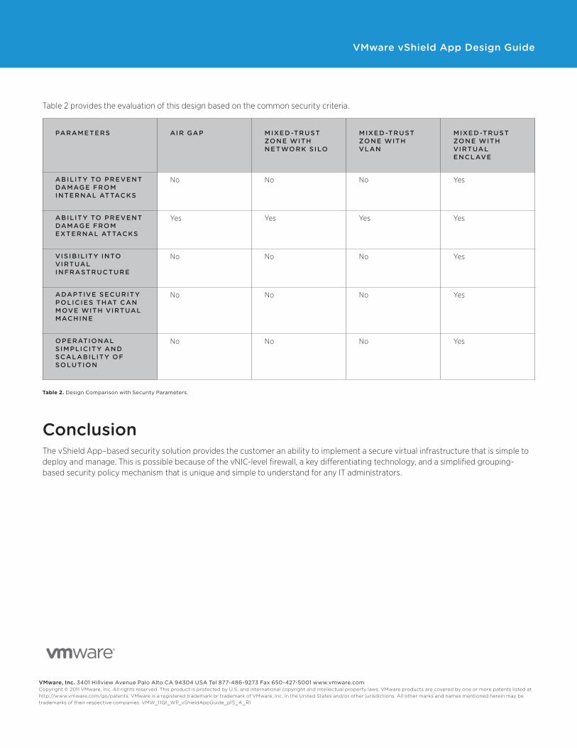
Table 2 provides the evaluation of this design based on the common security criteria.
PARAMETERS AIR GAP MIXED-TRUST ZONE WITH NETWORK SILO
MIXED-TRUST ZONE WITH VLAN
MIXED-TRUST ZONE WITH VIRTUAL ENCLAVE
ABILITY TO PREVENT DAMAGE FROM INTERNAL ATTACKS
No No No Yes
ABILITY TO PREVENT DAMAGE FROM EXTERNAL ATTACKS
Yes Yes Yes Yes
VISIBILITY INTO VIRTUAL INFRASTRUCTURE
No No No Yes
ADAPTIVE SECURITY POLICIES THAT CAN MOVE WITH VIRTUAL MACHINE
No No No Yes
OPERATIONAL SIMPLICITY AND SCALABILITY OF SOLUTION
No No No Yes
Table 2. Design Comparison with Security Parameters.
ConclusionThe vShield App–based security solution provides the customer an ability to implement a secure virtual infrastructure that is simple to deploy and manage. This is possible because of the vNIC-level firewall, a key differentiating technology, and a simplified grouping-based security policy mechanism that is unique and simple to understand for any IT administrators.
VMware, Inc. 3401 Hillview Avenue Palo Alto CA 94304 USA Tel 877-486-9273 Fax 650-427-5001 www.vmware.comCopyright © 2011 VMware, Inc. All rights reserved. This product is protected by U.S. and international copyright and intellectual property laws. VMware products are covered by one or more patents listed at http://www.vmware.com/go/patents. VMware is a registered trademark or trademark of VMware, Inc. in the United States and/or other jurisdictions. All other marks and names mentioned herein may be trademarks of their respective companies. VMW_11Q1_WP_vShieldAppGuide_p15_A_R1