department of space isro telemetry tracking and …
TRANSCRIPT
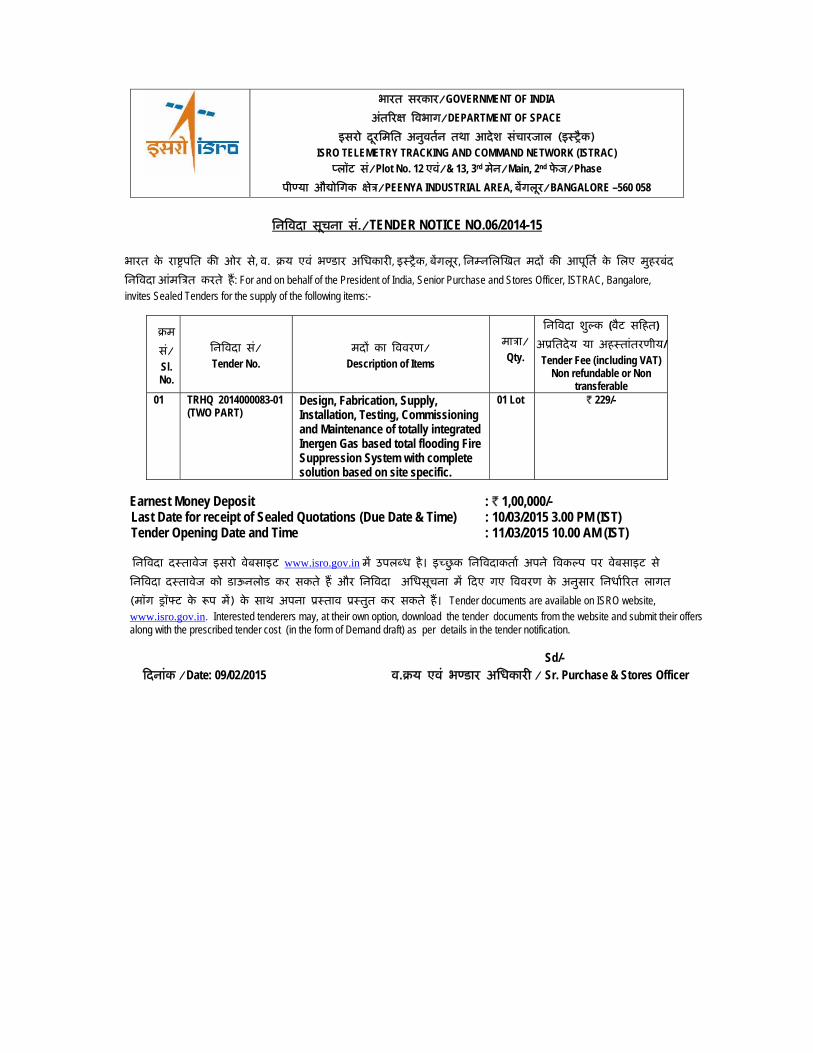
िनिवदा सचूना सं./TENDER NOTICE NO.06/2014-15
भारत के राष्टर्पित की ओर से, व. बय एवं भण्डार अिधकारी, इःशैक, बेंगलूर, िनम्निलिखत मदों की आपूितर् के िलए मुहरबंद िनिवदा आंमिऽत करते हैं: For and on behalf of the President of India, Senior Purchase and Stores Officer, ISTRAC, Bangalore, invites Sealed Tenders for the supply of the following items:-
बम सं/ Sl. No.
िनिवदा सं/ Tender No.
मदों का िववरण/ Description of Items
माऽा/ Qty.
िनिवदा शुल्क (वैट सिहत) अूितदेय या अहःतांतरणीय/ Tender Fee (including VAT)
Non refundable or Non transferable
01 TRHQ 2014000083-01 (TWO PART)
Design, Fabrication, Supply, Installation, Testing, Commissioning and Maintenance of totally integrated Inergen Gas based total flooding Fire Suppression System with complete solution based on site specific.
01 Lot ` 229/-
Earnest Money Deposit : ` 1,00,000/-
Last Date for receipt of Sealed Quotations (Due Date & Time) : 10/03/2015 3.00 PM (IST) Tender Opening Date and Time : 11/03/2015 10.00 AM (IST)
िनिवदा दःतावेज इसरो वेबसाइट www.isro.gov.in में उपलब्ध है। इच्छुक िनिवदाकतार् अपने िवकल्प पर वेबसाइट से िनिवदा दःतावेज को डाऊनलोड कर सकते हैं और िनिवदा अिधसूचना में िदए गए िववरण के अनुसार िनधार्िरत लागत (मॉग सॉफ्ट के रूप में) के साथ अपना ूःताव ूःतुत कर सकते हैं। Tender documents are available on ISRO website, www.isro.gov.in. Interested tenderers may, at their own option, download the tender documents from the website and submit their offers along with the prescribed tender cost (in the form of Demand draft) as per details in the tender notification.
Sd/-
िदनांक /Date: 09/02/2015 व.बय एवं भण्डार अिधकारी / Sr. Purchase & Stores Officer
भारत सरकार/GOVERNMENT OF INDIA अंतिरक्ष िवभाग/DEPARTMENT OF SPACE
इसरो दरूिमित अनुवतर्न तथा आदेश संचारजाल (इःशैक) ISRO TELEMETRY TRACKING AND COMMAND NETWORK (ISTRAC) प्लॉट सं/Plot No. 12 एवं/& 13, 3rd मेन/Main, 2nd फेज/Phase
पीण्या औद्योिगक के्षऽ/PEENYA INDUSTRIAL AREA, बेंगलूर/BANGALORE –560 058
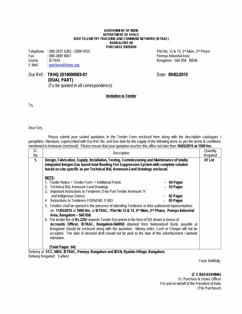
GOVERNMENT OF INDIA DEPARTMENT OF SPACE
ISRO TELEMETRY TRACKING AND COMMAND NETWORK (ISTRAC) BANGALORE-58
PURCHASE DIVISION Telephone : 080-2837 6383 / 2809 4555 Plot No. 12 & 13, 3rd Main, 2nd Phase Fax : 080-2809 4061 Peenya Industrial Area Grams : ISTRAC Bangalore - 560 058 INDIA E Mail : [email protected] Our Ref.: TRHQ 2014000083-01 Date: 09/02/2015 (DUAL PART)
(To be quoted in all correspondence)
Invitation to Tender To, Dear Sirs,
Please submit your sealed quotation, in the Tender Form enclosed here along with the description catalogues / pamphlets / literature, superscribed with Our Ref. No. and Due date for the supply of the following items as per the terms & conditions mentioned in Annexure (enclosed). Please ensure that your quotation reaches this office not later than 10/03/2015 at 1500 hrs.
Sl. No. Description Quantity
Required 1.
Design, Fabrication, Supply, Installation, Testing, Commissioning and Maintenance of totally integrated Inergen Gas based total flooding Fire Suppression System with complete solution based on site specific as per Technical Bid, Annexure-I and Drawings enclosed. NOTE: 1. Tender Notice + Tender Form + Additional Points – 04 Pages 2. Technical Bid, Annexure-I and Drawings – 53 Pages 3. Important instructions to Tenderers (Two Part Tender Annexure ‘X’ and Indigenous Stores) – 02 Pages 4 Instructions to Tenderers FORM NO. P.003 – 05 Pages 5. Tenders shall be opened in the presence of attending Tenderers or their authorized representatives on 11/03/2015 at 1000 Hrs. at ISTRAC, Plot No.12 & 13, 3rd Main, 2nd Phase, Peenya Industrial Area, Bangalore – 560 058. 6. The tender fee of Rs.229/- towards Tender Document in the form of DD drawn in favour of Accounts Officer, ISTRAC, Bangalore-560058 obtained from Nationalised Bank, payable at
Bangalore should be enclosed along with the quotation. Money order, Cash or Cheque will not be accepted. The date of demand draft should not be prior to the date of this advertisement / website intimation.
(Total Pages: 64)
01 Lot
Delivery at SCC, MOX, ISTRAC, Peenya, Bangalore and IDSN, Byalalu Village, Bangalore. Delivery Required: Earliest
Yours faithfully,
(C S BASAVANNA) Sr. Purchase & Stores Officer
For and on behalf of the President of India (The Purchaser)
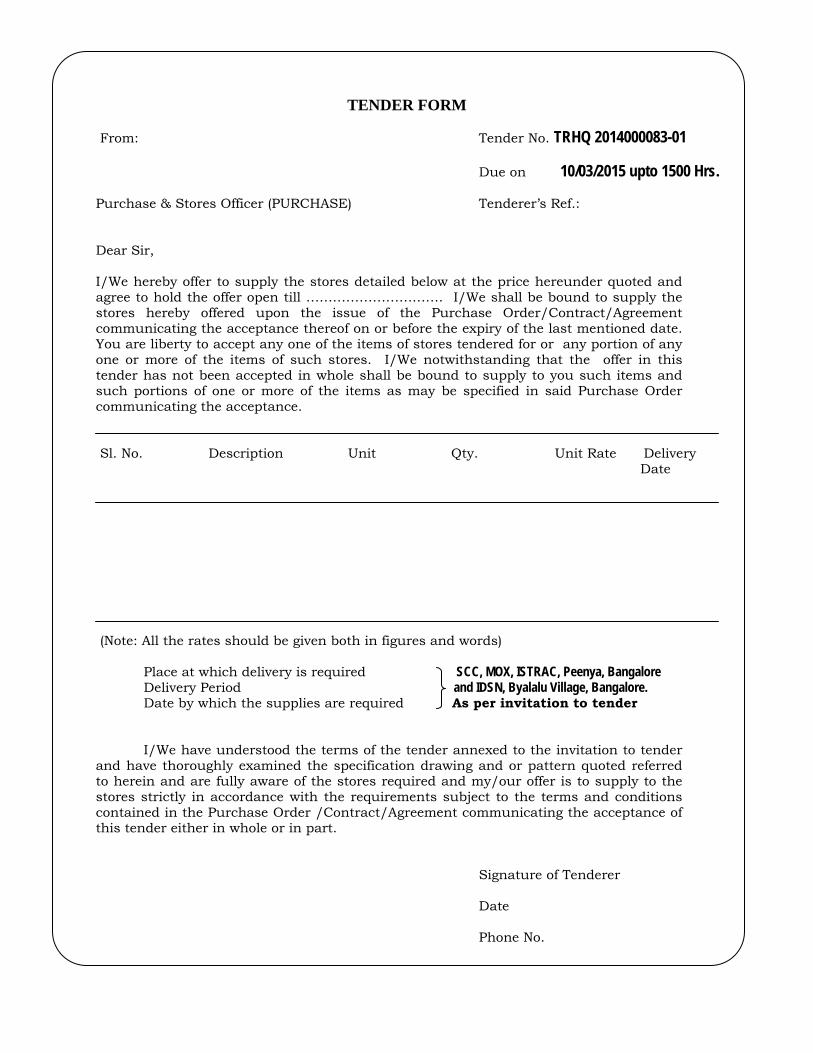
TENDER FORM
From: Tender No. TRHQ 2014000083-01
Due on 10/03/2015 upto 1500 Hrs. Purchase & Stores Officer (PURCHASE) Tenderer’s Ref.: Dear Sir, I/We hereby offer to supply the stores detailed below at the price hereunder quoted and agree to hold the offer open till …………………………. I/We shall be bound to supply the stores hereby offered upon the issue of the Purchase Order/Contract/Agreement communicating the acceptance thereof on or before the expiry of the last mentioned date. You are liberty to accept any one of the items of stores tendered for or any portion of any one or more of the items of such stores. I/We notwithstanding that the offer in this tender has not been accepted in whole shall be bound to supply to you such items and such portions of one or more of the items as may be specified in said Purchase Order communicating the acceptance. Sl. No. Description Unit Qty. Unit Rate Delivery Date (Note: All the rates should be given both in figures and words) Place at which delivery is required SCC, MOX, ISTRAC, Peenya, Bangalore Delivery Period and IDSN, Byalalu Village, Bangalore. Date by which the supplies are required As per invitation to tender I/We have understood the terms of the tender annexed to the invitation to tender and have thoroughly examined the specification drawing and or pattern quoted referred to herein and are fully aware of the stores required and my/our offer is to supply to the stores strictly in accordance with the requirements subject to the terms and conditions contained in the Purchase Order /Contract/Agreement communicating the acceptance of this tender either in whole or in part. Signature of Tenderer Date Phone No.
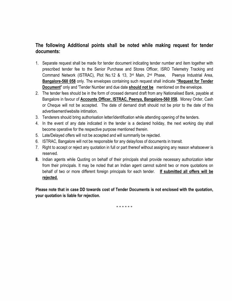
The following Additional points shall be noted while making request for tender documents: 1. Separate request shall be made for tender document indicating tender number and item together with
prescribed tender fee to the Senior Purchase and Stores Officer, ISRO Telemetry Tracking and
Command Network (ISTRAC), Plot No.12 & 13, 3rd Main, 2nd Phase, Peenya Industrial Area,
Bangalore-560 058 only. The envelopes containing such request shall indicate “Request for Tender
Document" only and 'Tender Number and due date should not be mentioned on the envelope.
2. The tender fees should be in the form of crossed demand draft from any Nationalised Bank, payable at
Bangalore in favour of Accounts Officer, ISTRAC, Peenya, Bangalore-560 058. Money Order, Cash
or Cheque will not be accepted. The date of demand draft should not be prior to the date of this
advertisement/website intimation.
3. Tenderers should bring authorisation letter/identification while attending opening of the tenders.
4. In the event of any date indicated in the tender is a declared holiday, the next working day shall
become operative for the respective purpose mentioned therein.
5. Late/Delayed offers will not be accepted and will summarily be rejected.
6. ISTRAC, Bangalore will not be responsible for any delay/loss of documents in transit.
7. Right to accept or reject any quotation in full or part thereof without assigning any reason whatsoever is
reserved.
8. Indian agents while Quoting on behalf of their principals shall provide necessary authorization letter
from their principals. It may be noted that an Indian agent cannot submit two or more quotations on
behalf of two or more different foreign principals for each tender. If submitted all offers will be
rejected.
Please note that in case DD towards cost of Tender Documents is not enclosed with the quotation,
your quotation is liable for rejection.
* * * * * *
1
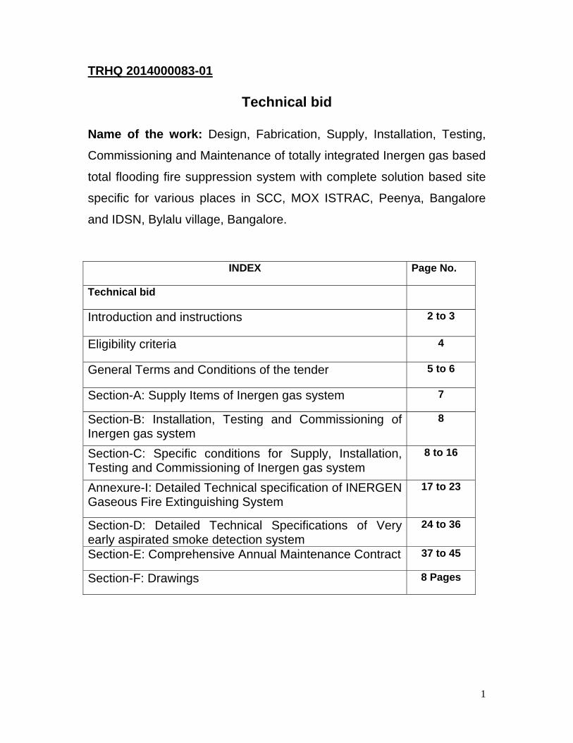
TRHQ 2014000083-01
Technical bid
Name of the work: Design, Fabrication, Supply, Installation, Testing,
Commissioning and Maintenance of totally integrated Inergen gas based
total flooding fire suppression system with complete solution based site
specific for various places in SCC, MOX ISTRAC, Peenya, Bangalore
and IDSN, Bylalu village, Bangalore.
INDEX Page No.
Technical bid
Introduction and instructions 2 to 3
Eligibility criteria 4
General Terms and Conditions of the tender 5 to 6
Section-A: Supply Items of Inergen gas system 7
Section-B: Installation, Testing and Commissioning of Inergen gas system
8
Section-C: Specific conditions for Supply, Installation, Testing and Commissioning of Inergen gas system
8 to 16
Annexure-I: Detailed Technical specification of INERGEN Gaseous Fire Extinguishing System
17 to 23
Section-D: Detailed Technical Specifications of Very early aspirated smoke detection system
24 to 36
Section-E: Comprehensive Annual Maintenance Contract 37 to 45
Section-F: Drawings 8 Pages
2
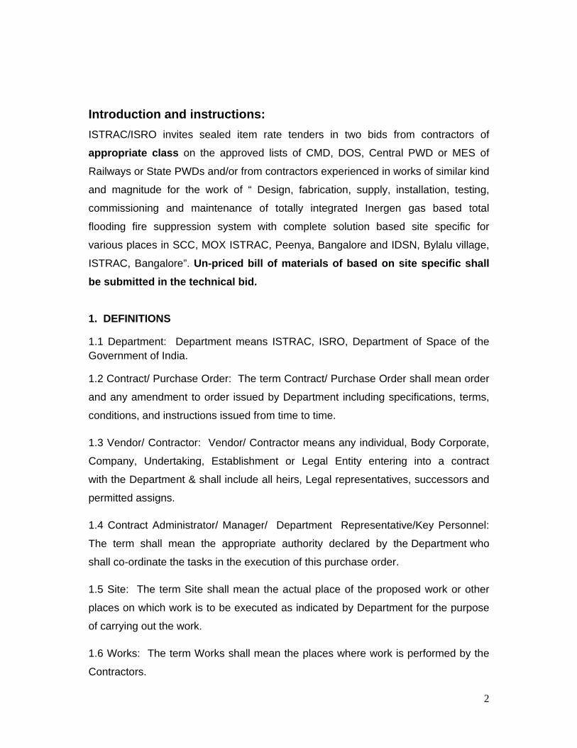
Introduction and instructions: ISTRAC/ISRO invites sealed item rate tenders in two bids from contractors of
appropriate class on the approved lists of CMD, DOS, Central PWD or MES of
Railways or State PWDs and/or from contractors experienced in works of similar kind
and magnitude for the work of “ Design, fabrication, supply, installation, testing,
commissioning and maintenance of totally integrated Inergen gas based total
flooding fire suppression system with complete solution based site specific for
various places in SCC, MOX ISTRAC, Peenya, Bangalore and IDSN, Bylalu village,
ISTRAC, Bangalore”. Un-priced bill of materials of based on site specific shall be submitted in the technical bid.
1. DEFINITIONS
1.1 Department: Department means ISTRAC, ISRO, Department of Space of the Government of India.
1.2 Contract/ Purchase Order: The term Contract/ Purchase Order shall mean order
and any amendment to order issued by Department including specifications, terms,
conditions, and instructions issued from time to time.
1.3 Vendor/ Contractor: Vendor/ Contractor means any individual, Body Corporate,
Company, Undertaking, Establishment or Legal Entity entering into a contract
with the Department & shall include all heirs, Legal representatives, successors and
permitted assigns.
1.4 Contract Administrator/ Manager/ Department Representative/Key Personnel:
The term shall mean the appropriate authority declared by the Department who
shall co-ordinate the tasks in the execution of this purchase order.
1.5 Site: The term Site shall mean the actual place of the proposed work or other
places on which work is to be executed as indicated by Department for the purpose
of carrying out the work.
1.6 Works: The term Works shall mean the places where work is performed by the
Contractors.
3
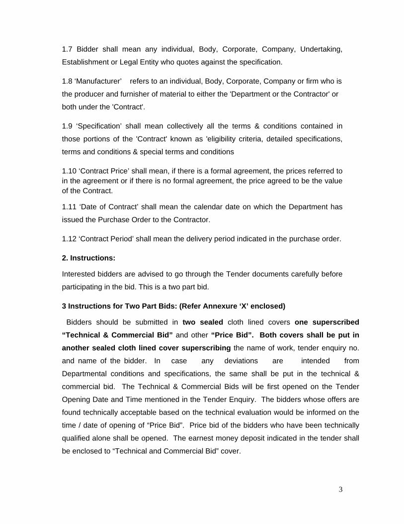
1.7 Bidder shall mean any individual, Body, Corporate, Company, Undertaking,
Establishment or Legal Entity who quotes against the specification.
1.8 ‘Manufacturer’ refers to an individual, Body, Corporate, Company or firm who is
the producer and furnisher of material to either the 'Department or the Contractor' or
both under the 'Contract'.
1.9 ‘Specification’ shall mean collectively all the terms & conditions contained in
those portions of the 'Contract' known as 'eligibility criteria, detailed specifications,
terms and conditions & special terms and conditions
1.10 ‘Contract Price’ shall mean, if there is a formal agreement, the prices referred to in the agreement or if there is no formal agreement, the price agreed to be the value of the Contract.
1.11 ‘Date of Contract’ shall mean the calendar date on which the Department has
issued the Purchase Order to the Contractor.
1.12 ‘Contract Period’ shall mean the delivery period indicated in the purchase order.
2. Instructions:
Interested bidders are advised to go through the Tender documents carefully before
participating in the bid. This is a two part bid.
3 Instructions for Two Part Bids: (Refer Annexure ‘X’ enclosed)
Bidders should be submitted in two sealed cloth lined covers one superscribed “Technical & Commercial Bid” and other “Price Bid”. Both covers shall be put in another sealed cloth lined cover superscribing the name of work, tender enquiry no.
and name of the bidder. In case any deviations are intended from
Departmental conditions and specifications, the same shall be put in the technical &
commercial bid. The Technical & Commercial Bids will be first opened on the Tender
Opening Date and Time mentioned in the Tender Enquiry. The bidders whose offers are
found technically acceptable based on the technical evaluation would be informed on the
time / date of opening of “Price Bid”. Price bid of the bidders who have been technically
qualified alone shall be opened. The earnest money deposit indicated in the tender shall
be enclosed to “Technical and Commercial Bid” cover.

4
Eligibility criteria
The following eligibility criteria shall be fixed for issuing of tender /
participating in the tender for the agencies
1. The agency should have successfully completed totally integrated Inergen
gas based total flooding fire suppression system for the value not less than
Rs.100.00 lakhs* in the past 5years ending 31.03.2014. Certified copies of
work orders and completion certificates issued by the authority concerned to
establish work experience. Completion certificates for works issued by Private
parties shall be supported by TDS (Tax deducted at source) certificates.
Without this evidence, offer will not be considered. * The value of executed
works shall be brought to current costing level by enhancing the actual value
of work at simple rate of 7% per annum, calculated from the date of
completion to last date of receipt of application for bids.
2. Contractor must document a professional level of expertise in plumbing and
electrical system installation, and must be either authorised or certified
reseller/ installer of fire suppression gas system (Inergen). Documentary
evidence shall be submitted for the above. Contractor shall be trained by the
manufacturer to calculate/ design, install, test and maintain the fire
suppression system and shall be able to produce a certificate stating such on
request. Contractor shall employ a person who shows proficiency at least to
NICET level IV certification in special hazards design.
3. The agency shall submit Demand draft or bank guarantee for the value of
Rs.1,00,000.00 towards earnest money deposit (EMD) drawn in the favour of
Senior Accounts Officer, ISTRAC, Bangalore payable at Bangalore in the
techno-commercial bid.
4. If EMD is not submitted by the agency, offer will not be considered.
5
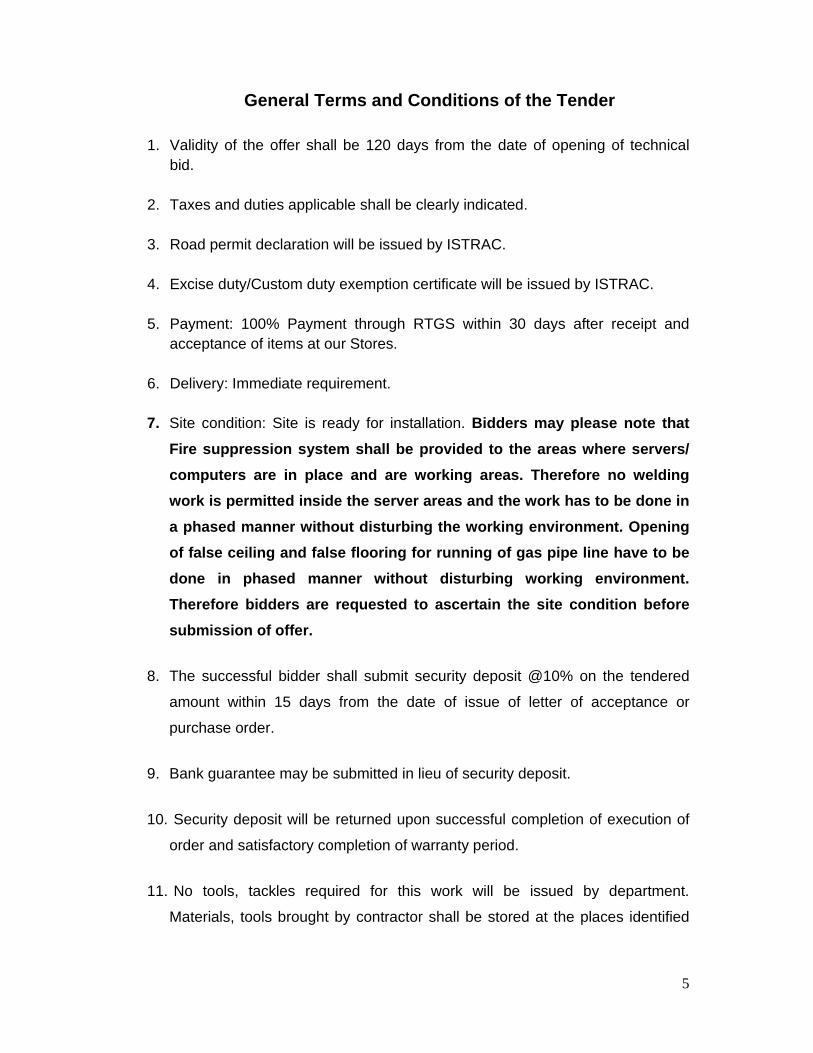
General Terms and Conditions of the Tender
1. Validity of the offer shall be 120 days from the date of opening of technical bid.
2. Taxes and duties applicable shall be clearly indicated.
3. Road permit declaration will be issued by ISTRAC.
4. Excise duty/Custom duty exemption certificate will be issued by ISTRAC.
5. Payment: 100% Payment through RTGS within 30 days after receipt and acceptance of items at our Stores.
6. Delivery: Immediate requirement.
7. Site condition: Site is ready for installation. Bidders may please note that Fire suppression system shall be provided to the areas where servers/ computers are in place and are working areas. Therefore no welding work is permitted inside the server areas and the work has to be done in a phased manner without disturbing the working environment. Opening of false ceiling and false flooring for running of gas pipe line have to be done in phased manner without disturbing working environment. Therefore bidders are requested to ascertain the site condition before submission of offer.
8. The successful bidder shall submit security deposit @10% on the tendered
amount within 15 days from the date of issue of letter of acceptance or
purchase order.
9. Bank guarantee may be submitted in lieu of security deposit.
10. Security deposit will be returned upon successful completion of execution of
order and satisfactory completion of warranty period.
11. No tools, tackles required for this work will be issued by department.
Materials, tools brought by contractor shall be stored at the places identified
6
by engineer in charge. No lockable stores or cupboards will be provided by
department.
12. Design shall be based on the requirement specified in the tender and as
per site condition. Hence tenderer shall visit the site before quoting. Therefore it is the responsibility of the contractor who himself shall acquaint with site condition and quote accordingly.
13. Contractor shall include civil works involved such as modifying false ceiling, false flooring, realigning them and match with existing pattern and ensuring the aesthetic appearance. Civil works involved for providing gas cylinder storage room will be done by department.
14. Tenderers shall separately indicate their comprehensive AMC charges (including supply of necessary spares) for a period of five years (after the expiry of warranty period).
15. The system shall be guaranteed for a period of 12 months from the date of
commissioning and handing over the system.
7
Section -A: Supply Items of Inergen gas system:
1. Supply INERGEN clean agent based fire suppression system with UL listed
components or any international laboratory approved, OEM factory filled, designed
for highest degree of protection and minimum extinguishing time with high speed
release of Inergen gas based on the concept of flooding fire protection for enclosed
areas at uniform extinguishing concentration as per NFPA 2001, comprising the
following components including supply of all other related accessories, connections
etc. complete as per detailed specification attached in Annexure-I.
i) High pressure seamless cylinder as per the design with concave bottom and
nock ring, CCOE approved complete with valve assembly, supervisory switch
connection for monitoring cylinder pressure, pressure gauge with safety burst disc
and safety cap etc. as required.
ii) Electric control head operated electrically from the Detection and control
system or locally with a manual lever on the control head.
iii) Pressure operated control head which allows for pressure actuation of
Inergen cylinders mounted directly on top of the Inergen cylinder valve.
iv) Discharge nozzles designed to provide the proper flow rate and 360 degree
distribution of Inergen to total flood a hazard area .
v) Master cylinder adapter kit used to actuate the Slave Cylinder Flexible
discharge hose to route the Inergen agent from storage cylinder to the discharge
piping by suitable flexible rubber hose with wire braided reinforcements. This hose
shall be connected to the discharge outlet of Inergen cylinder valve and
terminated at the system piping or discharged manifold.
vi) Manifold check valve installed at the discharge manifold to allow removal of
any Inergen cylinder from the manifold while still retaining a closed system.
vii) Flexible actuation hose pipe [pressure is directed to pressure operated
control head on each cylinder valve].
viii) Manual abort switch.
ix) Manual release switch
x) Inergen discharge signages

8
Section- B: Installation, testing and commissioning of Inergen gas system:
1. Installation, testing and commissioning (ITC) of INERGEN clean agent based fire
suppression system with UL listed components or any international laboratory
approved, OEM factory filled, designed for highest degree of protection and
minimum extinguishing time with high speed release of Inergen gas based on the
concept of flooding fire protection for enclosed areas at uniform extinguishing
concentration as per NFPA 2001, comprising the components indicated in Section- A
including supply of all other related accessories, connections etc. complete as per
detailed specification attached in Annexure-I.
Section-C: Specific conditions for Supply, installation, testing and commissioning of Inergen gas system:
1. GENERAL
a. Inergen system calculations shall be site specific and calculated by an accredited certified person at the time of tender.
b. No Tender will be accepted without site specific calculations. c. The firms shall submit complete set of printed catalogues, technical
specifications etc., of all the major components given by the manufacturer along
with the tender.
d. Necessary approvals by the concerned approval authority/ listing agencies shall
be enclosed with the offer in conformity with those specified in the detailed
specifications of the tender.
e. All references to manufacturer's model numbers and other pertinent information
herein is intended to establish minimum standards of performance, function and
quality.
2. CERTIFICATIONS
The agency shall submit certification from the major equipment manufacturer indicating that they are authorized to carry out the works on behalf of the principles and the performer of contract is duly factory trained for installing commissioning and maintenance of their equipments.
9
3. DRAWINGS
a. The firm shall submit a detailed installation programme immediately on award
of work clearly indicating the various activities to be taken up with detailed
time schedules.
b. The firm shall submit to the Engineer in charge 3 sets of detailed drawings for
approval before commencement of the work. The drawings shall include the
following.
c. Schematic diagram of the complete system proposed to be installed Detailed
wiring/cabling diagram Wiring / cabling diagrams shall indicate internal wiring
for each device and the interconnections between the items of equipment.
d. Annunciation layout, configurations, and terminations.
e. Manufacturer's name(s), model numbers, ratings, power requirements,
equipment layout, device arrangement, complete wiring point-to-point
diagrams, and conduit layouts.
4. COMMENCEMENT
a. The work shall be commenced only after getting approval of the drawings and
installation programme from the engineer-in-charge of the work.
b. The work shall be carried out by factory trained personnel. The work shall be
carried out strictly as per the approved installation programme and schematic/
wiring/cabling diagrams.
5. STORES AND SAFETY.
All the stores and materials required for satisfactory completion of the work shall be
arranged at work site by the contractor from his own sources. Space for storing the
materials may be provided on request from the contractor .However safe custody of
the materials / stores at the site will be responsibility of the contractor.
6. PACKING, FORWARDING AND STORAGE AT SITE:
Before dispatch to site, the equipment / component / materials shall be properly
packed so as to afford protection against transit damages and damages against
storage in open areas either at transporters’ premises or at work site. Special care
shall be taken in respect of sensitive items. When storage in open area is inevitable
10
proper water proof covering shall be provided to protect damages on account of
rain/water etc. However, damaged items shall be replaced as per the direction of
Engineer-in-charge.
7. SUPERVISION OF WORK
a. The CONTRACTOR shall personally, or through an authorized factory trained
supervisor who will constantly supervise the work from beginning to the
completion and shall, within reason, keep the same supervisor on the project
throughout the duration.
b. Site Engineer: The CONTRACTOR shall provide a Site Engineer to interface
with all appropriate subcontractors during the installation of the system. The
Site Engineer shall maintain continuous coordination with the Engineer in
Charge, keeping him abreast of progress and informed on any problems that
may develop. This is absolutely essential so that interference with daily facility operations is held to the minimum.
8. CO-ORDINATION:
Wherever the work is being carried out by more than one agency, it should be the
aim of different agencies that on their account the work of other agency/agencies is
not delayed. Full cooperation and full co-ordination is to be extended during progress
of work and at the time of testing. This is the contractor responsibility to have co-
ordination with other agencies in realising entire work.
9. SOFTWARE MODIFICATIONS
The contractor shall provide the services of a factory trained and authorized
technician to perform all system software modifications, upgrades or changes. The
contractor shall provide all hardware, software, programming tools and
documentation necessary to modify all the systems included within the scope of this
work. Modification includes addition and deletion of devices, circuits, zones and
changes to system operation and custom label changes for devices or zones. The
system structure and software shall place no limit on the type or extent of software
modifications at site.
11
10. EARTHING
The contractor shall extend necessary earthing to all the control panels and the other
equipment as per IE rules.
11. PRODUCTS
11.1. EQUIPMENT AND MATERIAL:
11.1.1 All equipment and components shall be new and the manufacturer's current
model. The materials, appliances, equipment and devices shall be tested and listed
by a nationally recognized approvals agency for use as part of a protective signalling
system, meeting the National Fire Alarm Code.
11.1.2 All equipment and components shall be installed in strict compliance with
manufacturers' recommendations. Consult the manufacturer's installation manuals
for all wiring diagrams, schematics, physical equipment sizes, etc., before beginning
system installation.
11.1.3 Equipment shall be attached to walls and ceiling/floor assemblies and shall be
held firmly in place (e.g., detectors shall not be supported solely by suspended
ceilings). Fasteners and supports shall be adequate to support the required load.
12. CONDUIT AND WIRE:
12.1. Conduit:
12.1.1. Conduit shall be in accordance with The National Electrical Code (NEC),
local and state requirements.
12.1.2. Where required, all wiring shall be installed in conduit or raceway. Conduit fill
shall not exceed 40% of interior cross sectional area where three or more cables are
contained within a single conduit.
12.1.3. Cable must be separated from any open conductors of power, or Class 1
circuits and shall not be placed in any conduit, junction box or raceway containing
these conductors as per NEC Article 760-29.
12.1.4. Wiring for 24 volt DC control, alarm notification, emergency communication
and similar power-limited auxiliary functions may be run in the same conduit as
12
initiating and signalling line circuits. All circuits shall be provided with transient
suppression devices and the system shall be designed to permit simultaneous
operation of all circuits without interference or loss of signals.
12.1.5. Conduit shall not enter the fire alarm control panel or any other remotely
mounted control panel equipment or back boxes, except where conduit entry is
specified by the FACP manufacturer.
12.1.6. Conduit shall be 20mm minimum.
12.2. Wire:
12.2.1. All system wiring shall be new.
12.2.2. Wiring shall be in accordance with local, state and national codes (e.g., NEC
Article 760) and as recommended by the manufacturer of the fire alarm system.
Number and size of conductors shall be as recommended by the fire alarm system
manufacturer.
12.2.3. All wires and cables shall be listed and/or approved by a recognized testing
agency for use with a protective signalling system.
12.2.4. Wire and cable not drawn in a conduit shall have a fire resistance rating
suitable for the installation as indicated in NFPA 70 (e.g., FRLS).
12.2.5. Wiring used for the multiplex communication circuit (SLC) shall be twisted
and unshielded and support a minimum wiring distance of 3500m. The design of the
system shall permit use of IDC and NAC wiring in the same conduit with the SLC
communication circuit.
12.2.6. All field wiring shall be electrically tested for open circuit and ground fault.
12.2.7. The fire alarm control panel shall be capable of t-tapping Class B (NFPA
Style 4) Signalling Line Circuits (SLCs). Systems that do not allow or have
restrictions in, for example, the amount of t-taps, length of t-taps etc., are not
acceptable.
13
12.3. Terminal Boxes, Junction Boxes and Cabinets:
12.3.1. All boxes and cabinets shall be UL listed or any international testing house
for their use and purpose.
12.3.2. Initiating circuits shall be arranged to serve like categories (manual, smoke,
water flow). Mixed category circuitry shall not be permitted except on signalling line
circuits connected to intelligent reporting devices.
13. PAINTING
All the equipments shall be painted and finished. Entire steel work shall undergo a
process of degreasing, pickling in acid, cold rinsing, phosphating, passivation,
spread with a high corrosion resistant primer and then finally finished with powder
coated painting under vacuum and backing.
14. COMMISSIONING / TESTING
After installation of the equipments, the same is to be commissioned and tested. The
tests are generally to be done for: 1.Functional tests 2.Performance tests
14.1. SYSTEM TESTING
14.1.1 The CONTRACTOR shall perform extensive tests of all equipment, document
the results and provide these results to the Engineer in Charge.
14.1.2. Execution: Activate all alarm or other output devices that are in the system
for proper operation, including supervisory and trouble circuit tests.
14.1.3 Report: A checkout report for each piece of equipment shall be prepared by
the CONTRACTOR and submitted to the Engineer in Charge. This report shall
include a complete listing of every device, the date it was tested and by whom, and
the results and date tested (if failure occurred during any previous tests). The final
test reports shall indicate that every device tested success. All the tests are to be
carried out in presence of the engineer-in-charge.
15. DOCUMENTATION
Three copies of all final operating and maintenance manuals (Hard & Soft copies)
shall be supplied within two weeks of hand-over in A4 binders. All system
14
documentation shall be in accordance with standard templates. Operating Manuals
shall comprise instructions on equipment safety checks, start-up and close-down
procedures, daily operation and full descriptions of operating features. These shall
match and comply fully with the software supplied, provide examples of operation
with supporting flow/strategy diagrams. Diagrams shall show the full diagrammatical
(network structures, outstations and peripherals) and physical layout of the system
and components. Maintenance Manuals shall comprise full descriptive and
maintenance details on each and every item of equipment supplied. Suppliers and
spare parts references, contacts, telephone numbers, and addresses shall be
supplied where relevant. Wiring schedules shall show the connection of each item of
equipment to the field equipment. Data sheets and maintenance instructions shall be
provided for each item of equipment. Diagrams showing the configuration of all
control and monitoring schemes, identifying the modules used their interconnections
and setting parameters, copy print-outs showing the individual outstation module
configurations and sequences.
15.1. As-built drawings: These drawings shall include but not be limited to:
15.1.1. Locations for all equipment components installed under this specification.
15.1.2. As-built conduit and cable layout diagrams
15.1.3. All drawings relating to all the systems shall be supplied A3/A4 sizes bound
into A4 ring binders as well as in soft copy. These shall include system, outstation
and user terminal configuration diagrams, listings and flow charts. Back-up copies of
all system configuration files and master software disks shall be supplied in an
appropriate lockable storage facility. All system and data files shall be current as at
the hand-over date, disks to be suitably identified and directories and files cross-
referenced in the maintenance manuals. The storage unit and key shall be handed to
the engineer-in -charge at hand-over.
16. HANDING OVER
16.1. After successful commissioning and Clearance of all tests as noted above, the
complete system is to be handed over to ISTRAC In order to have clear system
handover, the following documents have to be provided:
15
16.1.1. System diagram
16.1.2. Wiring diagram
16.1.3. Lists of parameters
16.1.4. Complete sets of O&M manuals
.17. SITE/USER TRAINING
17.1. The CONTRACTOR shall train key ISTRAC employees in the operation and
maintenance of the installed system. A training program shall be designed to provide
a comprehensive understanding and basic level of competence with the system. It
shall be sufficiently detailed to allow ISTRAC personnel to operate the system
independent of any outside assistance. The specified training schedule shall be
coordinated with the Engineer in charge.
17.2. The firm shall supply the following training for the ISTRAC CMD staffs.
17.2.1 Off-site: prior to hand-over at manufacturers works; non-specific system
structure, components and applications. Operation of user terminals, keyboards, use
of displays, overrides, passwords.
17.2.2. On-site: specific system structure, outstations locations, control strategy
overviews. Operation of user terminals, adjustments, graphs and alarm handling,
other networked components.
17.3. Engineers & selected staff:
17.3.1. Off-site: Prior to hand-over complete training courses at the manufacturers
works, instruction in the following; all as above but also including, configuration of
outstation and user terminals software, Windows/DOS file structures, password and
engineering utilities, fault- finding, tuning and maintenance.
17.3.2. On-site: while the ISTRAC CMD engineers shall attend the acceptance
demonstrations, the firm shall instruct them in the specific application of the system,
the structure and the control strategies adopted to meet the specification.
16
18. MAINTENANCE:
The contractor shall provide comprehensive maintenance for a period of 5years after
the successful completion of defect liability period and attend to any defects that may
arise in operation of the plant during this period including replacement of defective
equipments, components, detectors free of charge. Price for 5years maintenance
shall be indicated in the price bid separately.
19. DEFECT LIABILITY PERIOD / GUARANTEE:
All work performed and all materials and equipment furnished under this contract
shall be free from manufacturing and all other defects and shall remain so for a
period of 12 Months from the date of acceptance and handing over. The full cost of
maintenance, labour and materials required to correct any defect during this one
year period shall be included within the scope of this tender.
17
Annexure-I
Detailed Technical specification of INERGEN Gaseous Fire Extinguishing System
1. The INERGEN Extinguishing System shall comprise of the following: a. Extinguishing Agent b. Storage Cylinder or Cylinders Bank c. Quick opening valve d. Pressure gauges e. Control (actuation) line f. High pressure connection hose g. Manifold with non-return valves h. Pressure Reducing Unit i. Distribution piping j. Discharge nozzle
2. The above equipment shall be so connected as to perform as one complete
and functionally safe fire extinguishing system.
3. This extinguishing system shall conform to the VdS Guidelines on Gaseous
Fire Extinguishing System and the extinguishing agent shall comply with the
NFPA 2001 – Standards on Clean Agent Fire Extinguishing Systems.
4. The system as well as all individual parts shall be VdS Approved and tested to
EN 12094. This INERGEN Fire Extinguishing System should be known as IG
541 in NFPA 2001 and also as IG 52.40.08 in German Standards.
5. The INERGEN Gaseous Fire Extinguishing System should be designed as an
engineered system for total flooding extinguishing system. It shall be effective
on class A, B and C fires by lowering the oxygen content below the level that
supports combustion and at the same time human life is sustained.
6. INERGEN should have also been tested by FMRC for inerting capability and
the results should be that INERGEN is capable of inerting propane / air and
the methane / air mixtures at INERGEN concentrations between 40% and
50%.
2. System actuation
2.1. For the system energization the Pilot Cylinder shall be provided with an
electrical actuator properly mounted on the Quick Release Valve. When an actuation
signal is given by the Control Panel to the electrical actuator, the actuator should be

18
mechanically open the Quick Release Valve and the INERGEN released. The valves
of the slave cylinders shall open by pneumatic actuators using a proper pneumatic
control line and pneumatic release piston.
2.2. The cylinders shall be secured against reaction when the INERGEN is
discharged. They shall be easily removable from the mounting to permit complete
testing and actuation of the release and trip mechanism during inspection, without
discharging the agent.
3. Inergen (IG541) constitution
The INERGEN supplied shall comply with NFPA 2001 and have purity as following:
a. N2 52 ± 5 % b. Ar 40 ± 5 % c. CO2 8 ± 5 % d. Water content max 0.005 % by weight
4. Storage Cylinders
4.1. The INERGEN shall be stored in rechargeable cylinders, constructed, tested
and marked in accordance with Directive 84/525/CEE and DOT 3AA and shall have
inspection certificates from TUV-D, Stoomweeren (Holland), SDM (France), Aspagar
(Belgium) or any other equivalent Inspection Organization or the Seamless storage
cylinder & valve shall be approved by Chief Controller of Explosive ( CCOE).
Certificate shall be submitted along with supply.
4.2. Each Cylinder shall be provided with a valve for the automatic operation which
can be activated electrically, pneumatically or manually. It shall be delivered also
with a pressure measuring and analysing nozzle and a safety bursting disc which will
operate in case of over pressurization.
Technical Data:
4.1.2. Test Pressure: 300 Bar
4.2.2. Storage Pressure: 200 Bar
4.2.3. Nominal Capacity: 80LT/16,8Nm3 or 23.6 kg or as designed
4.2.4. Nominal Diameter: 12mm
4.2.5. Working Pressure: 200 bar/15oC
19
4.2.6. Over pressure release: 270 bar
4.2.7. Min control pressure: 100 bar
4.2.8. Max working pressure: 240 bar
4.2.9. Material Body: Brass
5. Pressure gauge
Every cylinder shall be provided with a pressure gauge (range from 0 to 300bar for
200bar systems which is connected at the special testing nozzle of the cylinder’s
quick release valve. The gauge connection and disconnection shall not cause any
INERGEN leakage.
6. Actuation
6.1. The release of the INERGEN agent from the storage shall be done by actuating
the quick release valve using an electromechanical actuator which operates at
24Vdc. Where multiple cylinder installation is used, the pilot cylinder’s valve shall
open by the use of an electromechanical actuator while the valves of the slave
cylinders shall open by agent pressure from pilot cylinder using a pneumatic control
line and pneumatic release piston.
Technical Data
6.1.1. Electrical actuator
6.1.2 Operating Voltage : 24 VDC
6.1.3. Power consumption : 15 W
6.1.4. Protection Standard : IP 65
6.1.5 Materials : Body – Red bronze Plastic coated Stainless Steel
6.1.6. Pneumatic Actuator (attached on the Quick Release Valve)
6.1.7. Minimum working pressure: 100 Bar 150 Bar
6.1.8. Material: Bronze Bronze
7. High pressure connection hose
7.1. All cylinders shall be connected to manifold using a flexible hose with the
following specifications:
20
Technical Data
7.1.1. Nominal diameter: 10 mm
7.1.2. Max operating pressure: 240 bar
7.1.3. Test pressure: 480 bar
7.1.4. Material : Thermoplastics Galvanized Steel
8. Manifold with non-return valves
8.1. When more than one cylinder is used, these shall be connected with flexible
hoses within a common manifold via non-return valves. It shall be possible to remove
one cylinder without the system interruption. The manifold shall be provided with
non-return valves. Its nominal diameter shall be DN 50 and can be connected up to 6
or 9 cylinders. When the non-return valves are not used they shall be protected with
special plugs.
Technical Data
8.1.1. Maximum operating pressure : 240 bar
8.1.2. Test pressure : 320 bar
8.1.3. Material:
8.1.3.1. Manifold : Galvanized Steel
8.1.3.2. Non-return valves : Brass
9. Pressure reducing unit
9.1 The pressure reduction device shall act as a flow restriction to reduce the
INERGEN storage pressure from 200 bar to 60 bar or lower in the distribution piping.
It shall be installed between the INERGEN manifold and the nozzle pipework and it
shall be of flanged type.
Technical Data
9.1.1. Nominal Diameter : DN 50 or DN 80
9.1.2. Diameter of reduction flow hole : 3 – 35 mm / DN 50
20 – 56 mm / DN 80
9.1.3. Material: Galvanized steel, bronze
21
9.1.4. Single Cylinder Pressure Reducer System
9.1.5. Diameter of reduction flow hole: 1 – 6 mm
9.1.6 Material: Galvanized steel, bronze
10. Piping : Pipe shall be SS 304 or SS 316
10.1. The entire pipe - network shall conform at least to the following requirements:
10.1.1. From the Cylinders up to the pressure reduction device
10.1.1.1. Max working pressure : 240 bar
10.1.1.2. Test pressure : 320 bar
10.1.1.3. Standardization : DIN 2448/17175
10.1.2. From the pressure reduction device up to nozzles
10.1.2.1. Max working pressure : 60 bar
10.1.2.2. Test pressure : 80 bar
10.1.2.3. Standardization : 15-50mm DIN 2458/1626/st 37.0
>DN 50 DIN 2448/17175/st 37.0
All fittings shall conform atleast to the following requirements:
10.1.3. From the Cylinders up to the pressure reduction device
10.1.3.1. Max working pressure : 240 bar
10.1.3.2. Test pressure : 320 bar
10.1.3.3. Standardization : ANSI B 16.11
10.1.4. From the pressure reduction device up to nozzles
10.1.4.1. Max working pressure : 60 bar
10.1.4.2. Test pressure : 80 bar
10.1.4.3. Standardization : GTW/DIN 2950
11. Discharge Nozzle
11.1. The selection and placement of the nozzles shall be such that the design
concentration of oxygen and CO2 concentrations shall be achieved in all parts of the
enclosure.
22
Technical Data
11.1.1. Nominal diameter : ½” or 1”
11.1.2. Application : Total flooding
11.1.3. Material : Bronze
11.1.4. Maximum Coverage: 30 m 2 up to 5 M room height.
11.2. The nozzle’s openings size shall be suitably designed based on the
working pressure and the design concentration.
11.3. Discharge nozzles shall be permanently marked with the diameter of the openings (Orifice size).
12. PIPE SIZING
The distribution network shall be suitably designed as per standard procedure. The
design calculation shall be submitted for approval.
13. PRESSURE RELIEF
Appropriate pressure relief shall be designed depending on the INERGEN discharge
rate and enclosure strength.
14. PROTECTED AREA REQUIREMENTS
14.1. The area to be protected shall be inspected and modifications if any shall be
proposed. Openings such as air conditioning louvers, cable trunks and ventilation
fans shall be suitably inspected and checked to ensure that they shall be shut before
INERGEN discharge. Extra INERGEN gas shall be discharged to compensate any
leakage if any.
14.2. Specifications and the Seamless Cylinder and the valves shall be approved by FM/UL and Chief Controller of Explosive Nagpur, India.
14.3. The Bidder shall submit a NOC for the Chief controller of Explosive Nagpur for
the storage containers against the cylinder identification nos. punched on them.
Welded cylinders for agent storage will not be acceptable - nor shall such Seamless
cylinders that do not have the approval of Chief Controller of Explosives, Nagpur.
23
14.4. The Cylinders shall be equipped with differential pressure valves & No
replacement parts shall be necessary to recharge the Inergen containers. Inergen
shall be discharged through the operation of an Electric (Solenoid) operated device
which releases the agent through a differential pressure valve. Systems that employ
explosive or pyrotechnic device shall not be permitted.
14.5. All system components shall be New and of Current manufacture and shall be
installed in accordance with local codes. ISTRAC reserves the Exclusive Rights to
unconditionally reject any and all such components which may not be, or are
suspected not to be of current manufacture; and / or on the grounds of authenticity of
the system components and designs.
14.6. The suppression agent shall be UL component recognized and the approved
agent shall be OEM factory filled and shall have filled certificate from the OEM. The
firm shall provide IN ORIGINAL all documentation such as Cylinder Manufacturing
Certificates, Test and Inspection Certificates & Fill Density Certificates.
15. Inergen Gas Release Panel:
15.1. The Inergen release signal output shall be from the microprocessor based
Main Fire Alarm Control panel with battery charger and battery stand-by. This panel
shall not be of the zone card type, but shall have the entire operational logic on a
microchip. The panel shall be capable of enhanced features such as printer and
computer interface, auto dialler interface, by addition of extra cards on the
motherboard. Detailed specification of Fire alarm panel where required is specified
separately.
15.2. Release of Inergen agent shall be accomplished by an electrical output from
the Inergen Gas Release Panel to the Electric control head release device and shall
be in accordance with the requirements set forth in the current edition of the National
Fire Protection Association Standard 2001.
24
Section: D: Detailed technical specifications of Very early aspirated smoke detection system This system is proposed only for Server room in ISSDC, IDSN, Bylalu village and INC server room, SCC, Peenya. But tenderers are advised to verify the existing fire alarm and smoke detection system at site for other areas to interface with tenderer’s proposed Inergen system in these areas. If existing smoke detection is not suitable to interface with the proposed Inergen system, tenderers may please include in their scope of providing suitable smoke detection system for such places. Unpriced bill of materials of such items shall be submitted in the technical bid.
1.1 General 1.1.1. A Very Early Smoke Detection System similar to the VESDA Laser PLUS
System shall be installed throughout the areas covering which are in the
enclosed tender drawings.
1.1.2. Displays are to be mounted in suitable racks and fitted to the Fire Sense 2800
Addressable fire alarm panel or Equivalent.
1.1.3. Aspire 2 Calculations shall be to be site specific and calculated by an
accredited certified person at the time of tender.
1.1.4. No Tender will be accepted without site specific Aspire 2 calculations.
1.1.5. The system shall consist of highly sensitive LASER-based Smoke Detectors
with aspirators connected to networks of sampling pipes.
1.1.6. Display unit shall be provided to monitor each detector and a Programmer
shall be supplied to configure the system.
1.2 Approvals The Very Early Smoke Detection System must be of type submitted, tested,
approved, and listed by:
1.2.1. FM (Factory Mutual), US
1.2.2. LPCB (Loss Prevention Certification Board), UK
1.2.3. UL (Underwriters Laboratories Inc), US
25
1.3 Codes, Standards or Regulations The entire installation shall be installed to comply with one or more of the following
codes or standards:
a. British Fire Protection Systems Association, Code of Practice for
Category 1 Aspirating Detection Systems
b. British Standards, BS 5839 Part 1 or BS 6266
c. NFPA Standards, US
d. NEC Standards, US
e. BIS
1.4 System Description 1.4.1 Design Requirements
1.4.1.1 Shall consist of a highly sensitive LASER-based smoke detector, aspirator,
and filter.
1.4.1.2 It shall be modular, with each detector monitored by a Display featuring
LEDs and a sounder. The system shall be configured by a Programmer
that is either integral to the system, portable or PC based. The system
shall allow programming of:
a. four smoke threshold alarm levels;
b. time delays;
c. faults including airflow, detector, power, filter and network as well as
an indication of the urgency of the fault;
d. Seven or more configurable relay outputs for remote indication of
alarm and fault conditions.
1.4.1.3 It shall consist of an air sampling pipe network to transport air to the
detection system, supported by calculations from a computer-based
design modelling tool.
1.4.1.4 Optional equipment may include intelligent remote displays and a high
level interface with the building fire alarm system.

26
1.4.1.5 Performance Requirements a. Shall be tested and approved to cover upto 2,000 sq.m.
b. Shall be approved to provide very early smoke detection and provide four output
levels corresponding to Alert, Action, Fire 1 and Fire 2. These levels shall be
programmable and able to be set at sensitivities ranging from 0.005 – 20%
obs/m.
c. Shall report any fault on the unit by using configurable fault output relays.
d. Shall be self-monitoring for filter contamination.
e. Shall incorporate a flow sensor in each pipe and provide staged airflow faults.
1.5 Document to be submitted 1.5.1. Product data and site drawings shall be submitted and shall include pipe
layout, operational calculations (ASPIRE™) and performance criteria in the tender.
In addition, approval of OEM authorizing tenderer to execute the work and evidence
of having executed similar work in India with contact details of clients shall be
submitted in the tender. Tenders without above documents received will be rejected
outright.
1.5.2. A copy of the manufacturer’s installation, operation and maintenance
manuals shall be supplied upon completion of the installation.
1.5.3. System commissioning data shall be supplied (in a format recommended by
the manufacturer and as per the instructions provided by the manufacturer) within
30 days of completion of the installation.
1.6 Quality Assurance
1.6.1 Qualifications 1.6.1.1. Manufacturer
The manufacturer shall have a minimum of 15 years manufacturing experience in
design of high sensitivity aspiration - type smoke detection systems. The
manufacturer shall be accredited to ISO 9002 for manufacturing.
1.6.1.2. Technology
Both Light Scattering and Particle Counting shall be utilised in this device as follows:
27
The Laser Detection Chamber shall be of the mass Light Scattering type and
capable of detecting a wide range of smoke particle types of varying size. A particle
counting method shall be employed for the purposes of
i) preventing large particles from affecting the true smoke reading
ii) Monitoring contamination of the filter (dust & dirt etc.) to automatically notify
when maintenance is required.
Note: The Particle counting circuitry shall not be used for the purpose of smoke
density measurement.
1.6.1.3. The Laser Detection Chamber shall incorporate a separate secondary clean
air feed from the filter; providing clean air barriers across critical detector optics to
eliminate internal detector contamination.
1.6.1.4. The detector shall not use adaptive algorithms to adjust the sensitivity from
that set during commissioning. A learning tool shall be provided to ensure the best
selection of appropriate alarm thresholds during the commissioning process.
1.6.1.5. Equipment Supplier
The equipment supplier shall be authorised and trained by the manufacturer to
calculate/design, install, test and maintain the air sampling system and shall produce
a certificate in this regard in the tender.
2. Products (smoke detection products) 2.1 Detector Assembly
2.1.1 The Detector, Filter, Aspirator and Relay Outputs shall be housed in a
mounting box and shall be arranged in such a way that air is drawn from the
fire risk and a sample passed through the Dual Stage Filter and Detector by
the Aspirator.
2.1.2 The Detector shall be LASER-based type and shall have an obscuration
sensitivity range of 0.005 – 20% obs/m.
2.1.3 The Detector shall have four independent field programmable smoke alarm
thresholds across its sensitivity range with adjustable time delays for each
threshold between 0-60 seconds.
28
2.1.4 The Detector shall also incorporate facilities to transmit the following faults
a. Detector
b. Air flow
c. Filter
d. System
e. Zone
f. Network
g. Power
h. Urgent and Minor faults: Minor faults shall be considered as servicing or
maintenance signals. Urgent faults indicate the unit may not be able to detect
smoke.
2.1.5 The detector shall have four in-line sample pipe inlets and must contain a flow
sensor for each pipe inlet. Both Minor and Urgent flow faults can be reported.
2.1.6 The filter must be a two-stage disposable filter cartridge. The first stage shall
be capable of filtering particles in excess of 20 microns from the air sample.
The second stage shall be ultra- fine, removing more than 99% of
contaminant particles of 0.3microns or larger, to provide a clean air barrier
around the detector’s optics to prevent contamination and increase service
life.
2.1.7 The aspirator shall be a purpose-designed rotary vane air pump. It shall be
capable of allowing for multiple sampling pipe runs up to 200m in total, (4 pipe
runs per detector) with a transport time of less than time specified by the
appropriate codes.
2.1.8 The Assembly must contain relays for alarm and fault conditions. The relays
shall be software programmable to the required functions. The relays must be
rated at 2 amp at 30 VDC. Remote relays shall also be offered and either
configured to replicate those on the detector or programmed differently.
2.1.9 The Assembly shall be able to be surface mounted to a wall or recessed in
the wall cavity or the unit may be inverted in either option.
29
2.1.10 The assembly shall have built-in event and smoke logging. It shall store
smoke levels, alarm conditions, operator actions and faults. The date and
time of each even shall be recorded. Each detector (zone) shall be capable of
storing up to 18,000 events and does not require the presence of a display in
order to do so.
2.2 Displays 2.2.1 A detector Display module may be located within the detector, a remote
mounting box or a 19 inch remote rack.
2.2.2 Each Display shall provide the following features at a minimum:
a. A 20 segment bar graph display.
b. Four independent high intensity alarm indicators, Alert, Action, Fire 1 and Fire2,
are corresponding to the four alarm thresholds of the detector.
c. Alarm threshold indicators for Alert, Action and Fire 1.
d. Detector fault and airflow fault indicators.
e. Faults originating in the particular VLP zone (Zone Fault) shall be distinguished
from those produced by the overall smoke detection system and from those
resulting from network wiring errors (Network Fault). LED indicators shall be
provided for each fault category.
f. Minor and urgent fault LED indicators.
g. A remotely mounted Display may be equipped with 7 or 12 configurable relays
for signalling alarm and fault conditions.
h. Four buttons supporting the following features:
2.2.3. Mode/Test: Scrolls through the information on the Display’s digital display:
Sensitivity (Fire 1 Threshold setting), current smoke level and VLP Zone number.
When pressed and held, initiates a lamp test on the individual display module.
2.2.4. Silence - Silences all devices on the system
2.2.5. Reset - Unlatches all latched alarm conditions on the assigned VLP zone.
2.2.6. Isolate - Isolates the individual VLP zone (inhibits Alarm and Fault relays and
initiates Isolate relay).
30
2.3 Programmer 2.3.1 When required, a Programmer module may be located within the detector, a
remote mounting box, a 19 inch remote rack, or in a portable hand-held unit.
Alternatively, programming may be performed using a Windows application running
on a PC connected through a High Level Interfacing unit.
2.3.1 Each Programmer shall support the following features at a minimum:
a. Programming of any device on the VESDAnet system.
b. Viewing of the status of any device in the system.
c. Adjustment of the alarm thresholds of a nominated detector.
d. Setting of Day/night, weekend and holiday sensitivity threshold settings.
e. To automatically configure the detector’s alarm threshold settings to suit
the current environment.
f. Multi-level password control.
g. Programmable latching or non-latching relay operation.
h. Programmable energized or de-energized relays.
i. Programmable high and low flow settings for airflow supervision.
j. Programmable aspirator speed control.
k. Programmable maintenance intervals.
l. Facilities for referencing with time dilution compensation.
m. Testing of relays assigned to a specific zone to aid commissioning.
2.4 Device Networking Requirements 2.4.1 The devices in the smoke detection system shall be capable of
communicating with each other via twisted pair RS485 cable. The network
shall be able to support up to 250 devices (detectors, displays and
programmers), of which at least 100 detectors can be supported.
2.4.2 The network shall be capable of being configured in a fault tolerant loop for
both short circuit and open circuit. Any communication faults shall be
reported unambiguously and shall be clearly attributable to an individual
device or wire link in the fault messages.
31
2.4.3 PC based configuration tools shall be available to configure and manage the
network of detectors.
2.5 Digital Communication Port shall comply with EIA RS485 Protocol.
2.6 Application 2.6.1 Detection Alarm Levels The laser based aspirating detection system shall have four (4) independently
programmable alarm thresholds. The four alarm levels may be used as follows:
a. Alarm Level 1 (Alert)
Activate a visual and audible alarm in the fire risk area.
b. Alarm Level 2 (Action)
Activate the electrical/electronic equipment shutdown relay and activate visual
and audible alarms in the Security Office or other appropriate location.
c. Alarm Level 3 (Fire 1)
Activate an alarm condition in the Fire Alarm Control Panel to call the Fire
Brigade and activate all warning systems.
d. Alarm Level 4 (Fire 2)
Activate a suppression system and/or other suitable countermeasures (e.g.
evacuation action or shut down of systems).
NOTE: The alarm level functions as listed are possible scenarios. Consideration
should be given to the best utilization of these facilities for each application and the
requirements of Indian authorities.
2.6.2 Initial Detection Alarm Settings Initial settings for the alarm levels shall be determined by the requirements of the fire
zone. However, the setting for Fire 1 (Alarm Level 3) shall always appear as 100%
on the bar graph scale. Default settings of the unit shall be:
a. Alarm Level 1 (Alert) 0.08% Obs/m b. Alarm Level 2 (Action) 0.14% Obs/m c. Alarm Level 3 (Fire 1) 0.2% Obs/m d. Alarm Level 4 (Fire 2) 2.0% Obs/m
32
2.6.3 Initial (factory default) Alarm Delay Thresholds Initial (factory default) settings for the alarm delay threshold shall be:
a. Alarm Level 1 (Alert) 10 seconds b. Alarm Level 2 (Action) 10 seconds c. Alarm Level 3 (Fire 1) 10 seconds d. Alarm Level 4 (Fire 2) 10 seconds e. Fault Alarm 5 seconds
2.6.4 Fault Alarms The Detector Fault relay shall be connected to the appropriate alarm zone on the
Fire Alarm Control Panel in such a way that a Detector Fault would register a fault
condition on the FACP. The Minor Fault and Isolate relays shall also be connected
to the appropriate control system.
2.6.5 Power Supply and Batteries 2.6.5.1. The system shall be powered from 230V, 50HZ AC UPS. System shall
convert AC into DC to supply a regulated supply of nominally 24V DC. The battery
charger and battery shall comply with the relevant Codes, Standards or Regulations.
Typically 24 hours standby battery backup is required followed by 30 minutes in an
alarm condition.
2.6.5.2. UL 1481 listed (provided the power supply and standby batteries have been
appropriately sized / rated to accommodate the system’s power requirements).
2.7 Sampling Pipe Design
2.7.1 Sampling Pipe 2.7.1.1 The sampling pipe shall be smooth bore with an internal diameter between
15-25mm. normally; pipe with an outside diameter of 25mm and internal diameter of
21mm should be used.
2.7.1.2 The pipe material should be suitable for the environment in which it is
installed, or should be the material as required by the specifying body.
2.7.1.3 All joints in the sampling pipe must be air tight and made by using solvent
cement, except at entry to the detector.
33
2.7.1.4 The pipe shall be identified as Aspirating Smoke Detector Pipe (or similar
wording) along its entire length at regular intervals not exceeding the manufacturer’s
recommendation.
2.7.1.5 All pipes should be supported at not less than 1.5m centres, or that of the
local codes or standards.
2.7.1.6 The far end of each trunk or branch pipe shall be fitted with an end cap and
drilled with a hole appropriately sized to achieve the performance as specified and
as calculated by the system design.
2.7.2 Sampling Holes 2.7.2.1. Sampling holes of 2mm, or otherwise appropriately sized holes (see Section
3.03), shall not be separated by more than the maximum distance allowable for
conventional point detectors as specified in the relevant standards. Intervals may
vary according to calculations.
2.7.2.2. Each sampling point shall be identified in accordance with Codes or
Standards.
2.7.2.3 Consideration shall be given to the manufacturer’s recommendations and
standards in relation to the number of Sampling Points and the distance of the
Sampling Points from the ceiling or roof structure and forced ventilation systems.
3. Installation of the Detection system
The contractor shall install the system in accordance with the manufacturer's System
Design Manual.
3.1 The Capillary Sampling Network 3.1.1 Where false ceilings are installed, the sampling pipe shall be installed above
the ceiling, and Capillary Sampling Points shall be installed on the ceiling and
connected by means of a capillary tube.
3.1.2 The minimum internal diameter of the Capillary tube shall be 5mm, the
maximum length of the Capillary tube shall be 2m unless the manufacturers have
specified otherwise.
3.1.3 The Capillary tube shall terminate at a Ceiling Sampling Point specifically
designed and approved by the manufacturer. The performance characteristics of the
Sampling Points shall be taken into account during the system design.
34
3.2 Air Sampling Pipe Network Calculations 3.2.1. Air Sampling Pipe Network Calculations shall be provided by a sampling pipe
aspiration modelling program such as ASPIRE latest version. Pipework calculations
shall be supplied with the proposed pipe layout design to indicate the following
performance criteria:
3.2.2. Transport Time
The manufacturers recommended transport time (time taken for the smoke to enter
the pipe and reach the detector) for the least favourable sampling point is 60
seconds or less.
3.2.3. Balance %
The sample point balance for the pipe shall not be less than 70% as indicated by
ASPIRE. That is, the volume of air drawn from the last sampling point shall not be
less than 70% of the average volume of air through the other holes.
3.2.4. Share %
The sample hole share for the pipe shall not be less that 70% as indicated by
ASPIRE. i.e., the sum volume of air drawn through the sampling holes must always
be greater than 70% of the total volume of air entering the pipe (i.e. the End Vent
must not exceed 30% of the total flow).
3.3 Commissioning Tests
3.3.1 The contractor with the manufacturer’s representative shall commission the
entire installation in the presence of the Engineer in charge or his
representative.
3.3.2 All necessary instrumentation, equipment, materials and labour shall be
provided by the Contractor.
3.3.3 The Contractor shall record all tests and system calibrations and three copies
of these results shall be submitted to EIC and with one copy retained on site
in the System Log Book.
35
3.4 System Checks
3.4.1 Visually check all pipes to ensure that all joints, fittings, bends, sampling points,
etc., comply with the Specification.
3.4.2 Check the system to ensure the following features are operational and
programmed in accordance with the specification.
a. Alarm threshold levels (for both day and night settings), b. Pipes in use, c. Detector address, d. Display address, e. Time and date, f. Time delays, g. Air flow fault thresholds, h. Display buttons operable (Mode, Silence, Reset, Isolate), i. Referencing j. Units set to S.I.
3.4.3 Check to ensure that all ancillary warning devices operate as specified.
3.4.4 Check interconnection with Fire Alarm Control Panel to ensure correct
operation.
3.5 Tests
3.5.1 Introduce Smoke into the Detector Assembly to provide a basic functional test.
3.5.2 Introduce smoke to the least favourable Sampling Point in each Sampling
Pipe. Transport time is not to exceed the local codes.
3.5.3 If more than two bar graph divisions illuminate under normal conditions (no
smoke test), review event log for two weeks from date of commissioning and make
appropriate adjustments to the alarm and delay thresholds.
3.5.4 Activate the appropriate Fire Alarm zones and advise all concerned that the
system is fully operational. Fill out the log book and commissioning report
accordingly.
36
3.6 Handing over:
Fully commissioned system shall be handed over to EIC along with documents listed
above and the warranty certificate. Warranty for 12months shall commence from the
date of taken over the installation.

37
Section- E: Comprehensive Annual Maintenance Contract
Note: Scope and schedule of maintenance indicated below is for smoke
detection system. Tenderers are advised to submit the scope and schedule of
maintenance similarly for Inergen system also in the technical bid.
Please quote year wise rates for providing comprehensive annual maintenance for a period of five years from the date of expiry of warranty/ defect liability period in the price bid. Un-priced bill of materials shall be furnished in the technical bid.
The scope of work covered under AMC has been detailed below. Spares for day to
day satisfactory operations, spares required for preventive maintenance and spares
required for replacement of defective parts during break down maintenance shall
have to be included in the scope of the bidder.
1. Scope:
a. Agency has to carry out health check of system once as per the maintenance
schedule indicated elsewhere.
b. Preventive maintenance and break down maintenance of system shall be
carried out as per the instructions for the operation and maintenance of
manufacturer. Therefore maintenance schedule shall be in line with
manufacturer’s instruction.
c. The service provider shall have the staffs trained by the manufacturer.
d. Preparation of maintenance data for future records shall be done.
e. Replacement of any defective components or parts shall be done at free of
cost.
f. ISTRAC will only spare vacuum cleaner for cleaning purpose and ladder.
38
2. Inspection, Testing and Maintenance Requirements
2.1 Annual Frequency (Quarterly)
2.1.1 Control Equipment and Detector
2.1.1.1 Inspection
2.1.1.a. Verify equipment has no physical damage, not obstructed and is in normal
operating condition. If found defective, replace the same.
2.1.1.b. Verify the working conditions of all lamps and LEDs on all display modules. If
found defective, replace the same.
2.1.1.c. The power supply of the Air Sampling Smoke Detection System falls under
the requirements for Fire Detection and Alarm Systems and shall be inspected,
tested and maintained accordingly. If found defective, replace the same.
2.1.2 Sampling Pipe Network
2.1.2.1 Inspection
Inspect the sampling pipe network and connections to ensure that the pipe runs are
intact with no breaks (ex. pipe joints, end caps, capillary tube connections). If found
defective, replace the same.
2.1.2.2 Maintenance
Repair broken or loose pipe joints or caps when necessary.
2.2 Annual Frequency (half yearly)
2.2.1 Control Equipment and Detector
2.2.1.1 Inspection
2.2.1.1.a. Check the filter for excessive dust and/or clogging.
2.2.1.1.b. Check the raw airflow of the detector and compare to previous readings to
see that it is not progressively decreasing.
39
2.2.1.2 Testing
Perform test to verify all functions of the control equipment and detector will operate
properly. This includes supervision, outputs, isolate and other features specified by
equipment manufacturer.
2.2.1.3 Maintenance
Clean or replace filter when necessary.
2.2.2. Power Supply
The power supply of the Air Sampling Smoke Detection System falls under the
requirements for Fire Detection and Alarm Systems and shall be inspected, tested
and maintained accordingly. If found defective, replace the same.
2.2.3 Sampling Pipe Network
2.2.3.1 Inspection
Inspect the sampling pipe network to be clean and free of dirt that can cause
blockage by injecting a small amount of smoke into the last sampling hole to ensure
detector response.
2.2.3.2 Testing
2.2.3.2.a. Test the performance of the sampling pipe network by measuring the
suction pressure for each sampling hole and comparing to the airflow modelling
software results.
2.2.3.2.b.Test the transport time of the sampling pipe network by introducing a
smoke sample into the sample point furthest from the detector and measuring the
response time. Compare this time with the airflow modelling software results.
2.2.3.3 Maintenance
Clean sample pipe network if found clogged or breached with dirt.
40
2.3. Once in 2-Year Frequency
2.3.1 Sampling Pipe Network
2.3.1.1 Maintenance
2.3.1.1.a. Clean all capillary tube sampling points to remove dust build-up that can
cause blockage.
2.3.1.1.b Back-flush the sampling pipe network to remove dust build-up that can
cause blockage as per Manufacturer Guidelines for proper procedure.
2.4. Once in 4-Year Frequency
2.4.1 Control Equipment and Detector
2.4.1.1 Maintenance
For Xenon Light Source Detectors Only: Replace the detector with a refurbished
detector.
41
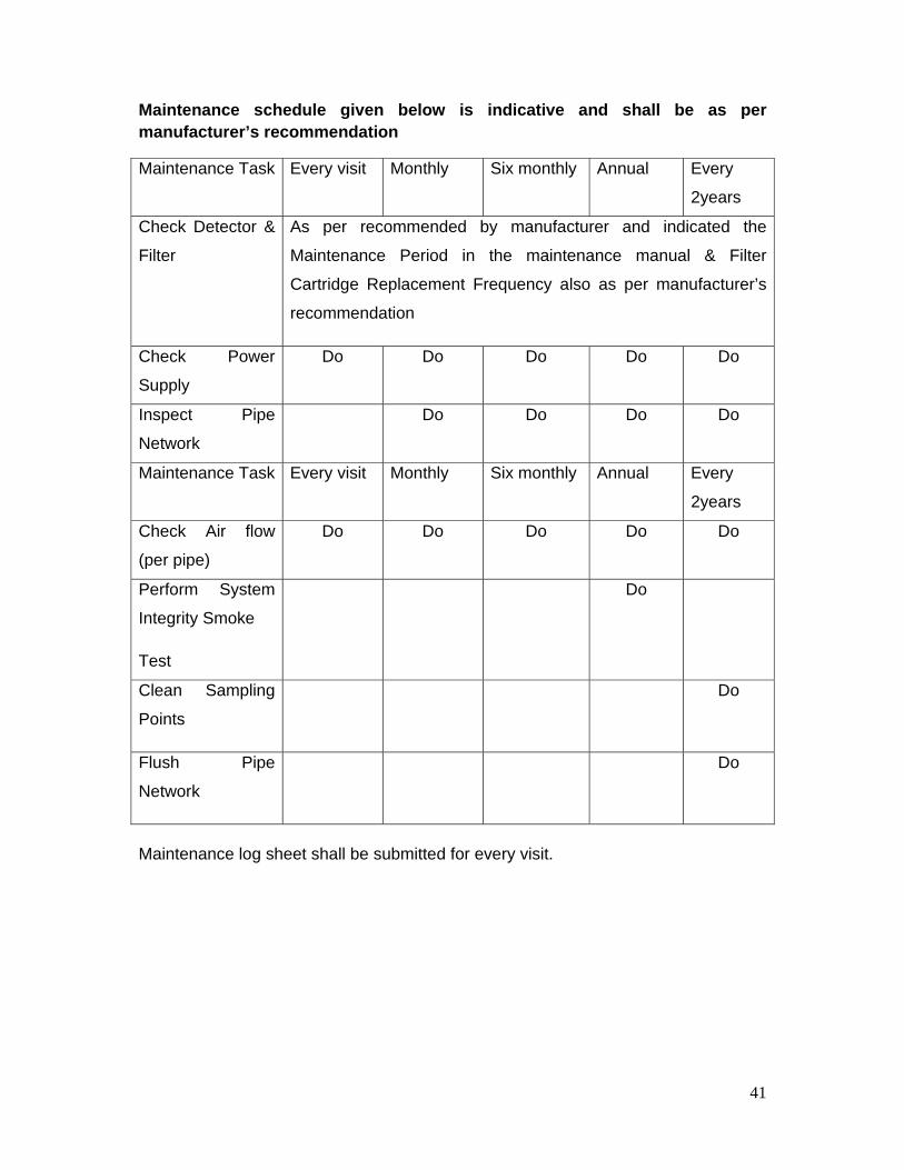
Maintenance schedule given below is indicative and shall be as per manufacturer’s recommendation
Maintenance Task Every visit Monthly Six monthly Annual Every
2years
Check Detector &
Filter
As per recommended by manufacturer and indicated the
Maintenance Period in the maintenance manual & Filter
Cartridge Replacement Frequency also as per manufacturer’s
recommendation
Check Power
Supply
Do Do Do Do Do
Inspect Pipe
Network
Do Do Do Do
Maintenance Task Every visit Monthly Six monthly Annual Every
2years
Check Air flow
(per pipe)
Do Do Do Do Do
Perform System
Integrity Smoke
Test
Do
Clean Sampling
Points
Do
Flush Pipe
Network
Do
Maintenance log sheet shall be submitted for every visit.
42
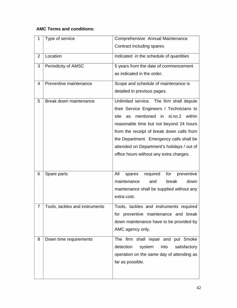
AMC Terms and conditions:
1 Type of service Comprehensive Annual Maintenance
Contract including spares
2 Location Indicated in the schedule of quantities
3 Periodicity of AMSC 5 years from the date of commencement
as indicated in the order.
4 Preventive maintenance Scope and schedule of maintenance is
detailed in previous pages.
5 Break down maintenance Unlimited service. The firm shall depute
their Service Engineers / Technicians to
site as mentioned in sl.no.2 within
reasonable time but not beyond 24 hours
from the receipt of break down calls from
the Department. Emergency calls shall be
attended on Department’s holidays / out of
office hours without any extra charges.
6 Spare parts All spares required for preventive
maintenance and break down
maintenance shall be supplied without any
extra cost.
7 Tools, tackles and instruments Tools, tackles and instruments required
for preventive maintenance and break
down maintenance have to be provided by
AMC agency only.
8 Down time requirements The firm shall repair and put Smoke
detection system into satisfactory
operation on the same day of attending as
far as possible.
43
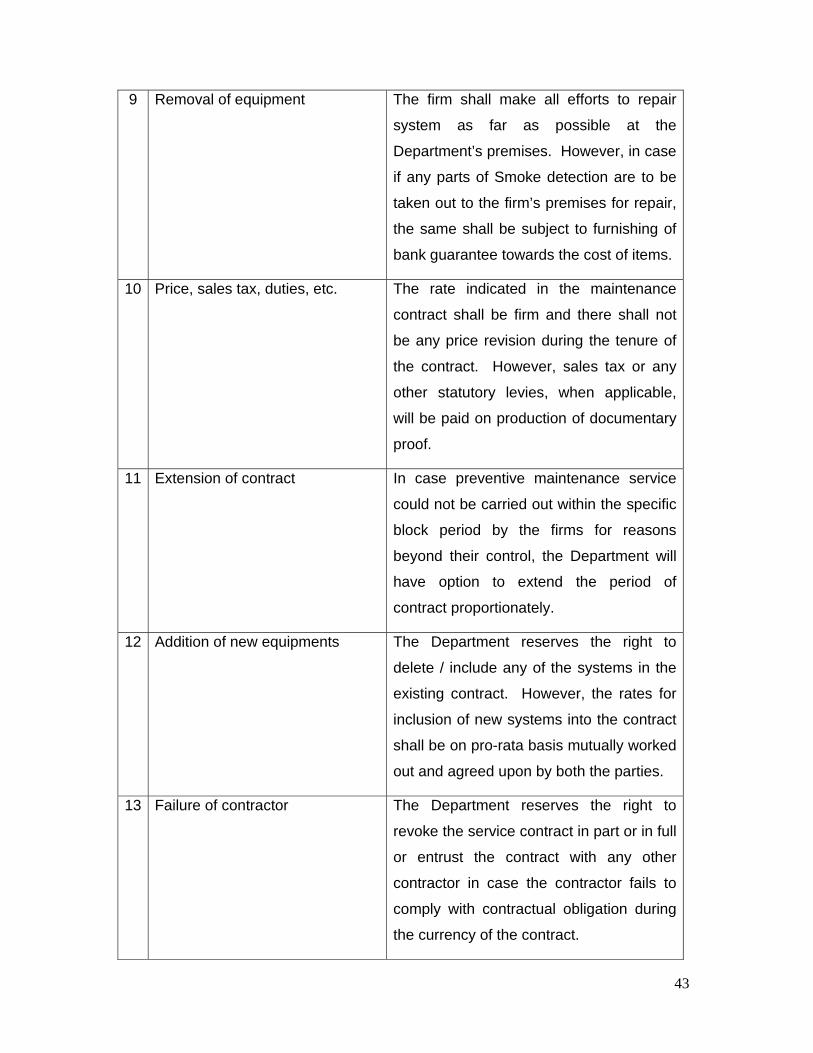
9 Removal of equipment The firm shall make all efforts to repair
system as far as possible at the
Department’s premises. However, in case
if any parts of Smoke detection are to be
taken out to the firm’s premises for repair,
the same shall be subject to furnishing of
bank guarantee towards the cost of items.
10 Price, sales tax, duties, etc. The rate indicated in the maintenance
contract shall be firm and there shall not
be any price revision during the tenure of
the contract. However, sales tax or any
other statutory levies, when applicable,
will be paid on production of documentary
proof.
11 Extension of contract In case preventive maintenance service
could not be carried out within the specific
block period by the firms for reasons
beyond their control, the Department will
have option to extend the period of
contract proportionately.
12 Addition of new equipments The Department reserves the right to
delete / include any of the systems in the
existing contract. However, the rates for
inclusion of new systems into the contract
shall be on pro-rata basis mutually worked
out and agreed upon by both the parties.
13 Failure of contractor The Department reserves the right to
revoke the service contract in part or in full
or entrust the contract with any other
contractor in case the contractor fails to
comply with contractual obligation during
the currency of the contract.

44
The contractor shall be responsible for
any loss to the Department as a result of
non-compliance of the contractual
obligations and breach of trust.
14 Relocation / shifting of
equipments
The Department reserves the right to
relocate the systems as and when
necessary.
15 Termination of contract It shall be open to Department to
terminate this contract at any time during
its currency by giving three months’ notice
to the firm in writing.
16 Fall clause The Annual Maintenance Service charges
quoted by the contractor under the
contract shall not in any event exceed the
lowest charges for the similar contract
entered into by the firm with any other
customer during the currency of the said
contract. At any time during the said
period, the contractor reduces the service
charges / or prices of spares to any other
persons / organizations / firms at a charge
lower than the amount payable by the
Department; he shall inform the
notification of such reduction to
Department. The price / charges payable
under the contract shall stand
correspondingly reduced from the date of
coming into force of such reduction.
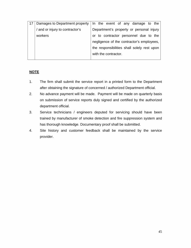
45
17 Damages to Department property
/ and or injury to contractor’s
workers
In the event of any damage to the
Department’s property or personal injury
or to contractor personnel due to the
negligence of the contractor’s employees,
the responsibilities shall solely rest upon
with the contractor.
NOTE
1. The firm shall submit the service report in a printed form to the Department
after obtaining the signature of concerned / authorized Department official.
2. No advance payment will be made. Payment will be made on quarterly basis
on submission of service reports duly signed and certified by the authorized
department official.
3. Service technicians / engineers deputed for servicing should have been
trained by manufacturer of smoke detection and fire suppression system and
has thorough knowledge. Documentary proof shall be submitted.
4. Site history and customer feedback shall be maintained by the service
provider.

1
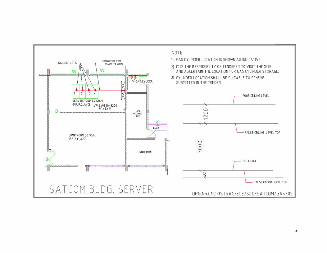
2
3
4
5
6
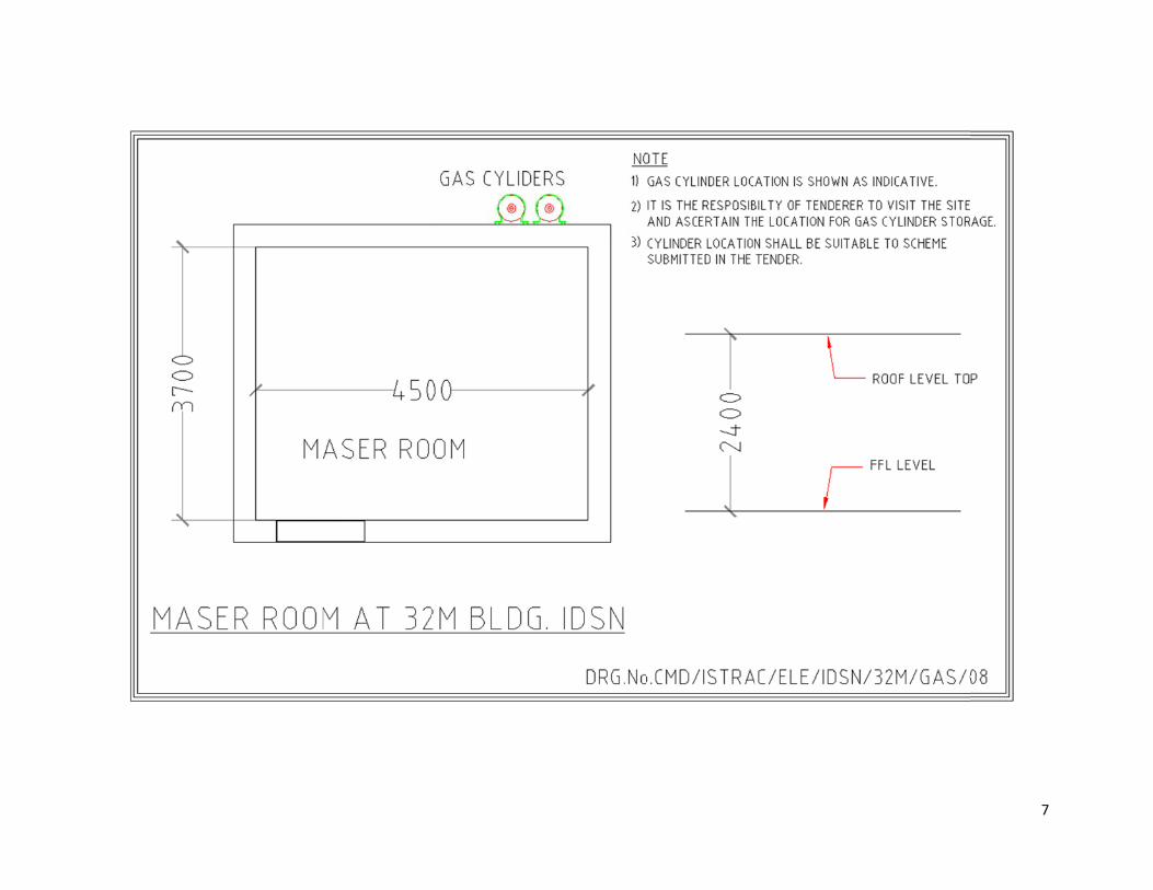
7
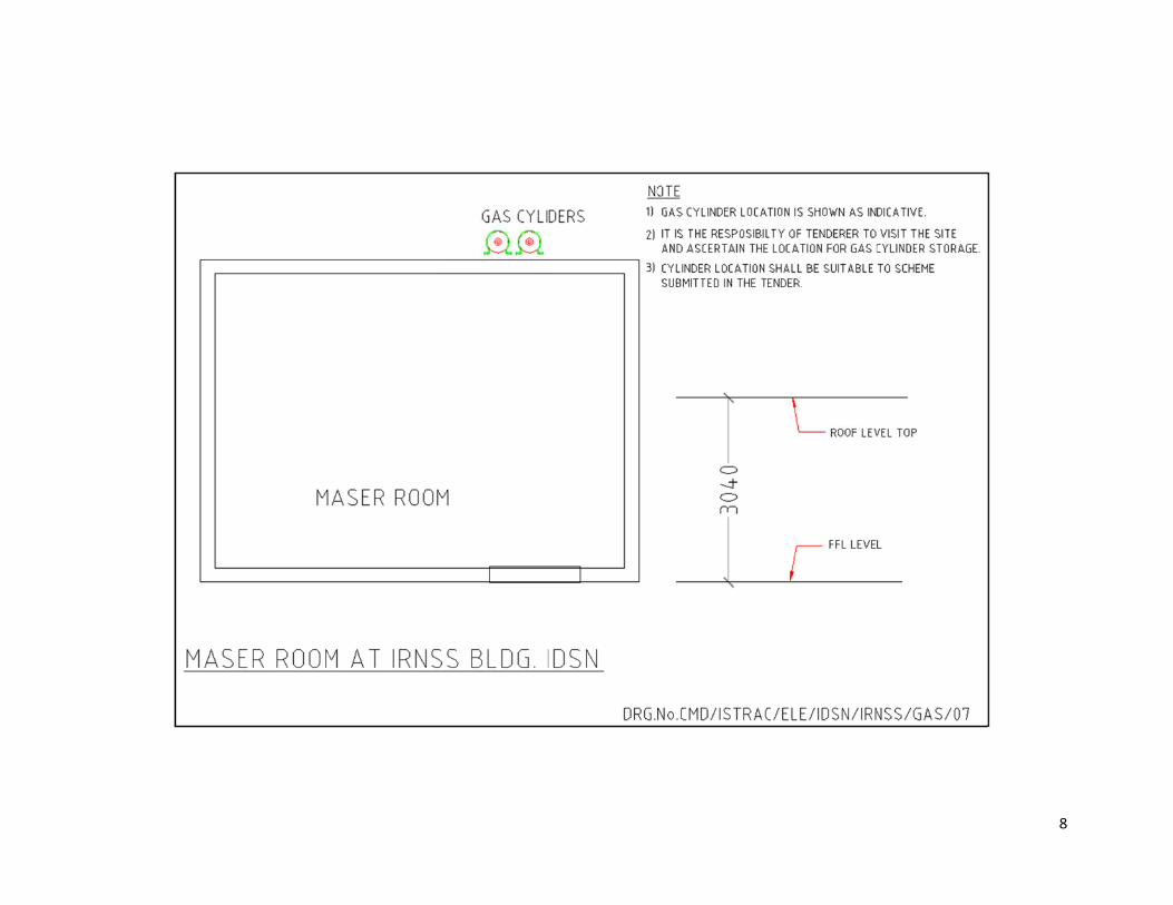
8

ANNEXURE ‘X’
IMPORTANT INSTRUCTIONS TO TENDERERS (TWO PART TENDER) 1. IT IS PROPOSED TO HAVE A TWO COVER SYSTEM FOR THIS TENDER: TECHNICAL AND COMMERCIAL PART IN ONE COVER PRICE PART IN ONE COVER 2. TECHNICAL AND COMMERCIAL PART
TECHNICAL AND COMMERCIAL PART SHOULD CLEARLY INDICATE IN ADDITION TO THE TECHNICAL DETAILS, PLACE OF
DELIVERY i.e, ISTRAC’s SITE, BANGALORE, SUPPORT OF SYSTEMS DURING WARRANTY AND POST WARRANTY PERIOD PAYMENT TERMS, VALIDITY, WARRANTY/GUARANTEE, DELIVERY PERIOD, DELIVERY SCHEDULE, LIST OF SIMILAR INSTALLATION, CATALOGUE ETC.,
COMPLETE TECHNICAL LITERATURE/LEAFLET RELEVANT TO THE OFFER ARE TO BE ENCLOSED TO THE TECHNICAL AND
COMMERCIAL PART OF THE TENDER PLEASE ENCLOSE A COMPLIANCE STATEMENT FOR ALL THE SPECIFICATION, TERMS/CONDITIONS (POINT BY POINT)
COVERED IN THE ENCLOSED TECHNICAL COMPLIANCE REPORT. ALSO, ENCLOSE A COPY OF THE DETAILS INDICATED IN PRICE QUOTATION (WITHOUT PRICES OR BY MASKING THE PRICES) MAINLY TO KNOW THE ITEMS/SPECIFICATIONS FOR WHICH YOU HAVE INDICATED PRICES IN PRICE BID. THIS PART SHOULD NOT CONTAIN PRICES.
IF THE TECHNICAL OFFER CONTAINS ANY PRICE INFORMATION THE OFFER IS LIABLE TO BE REJECTED.
3. PRICE PART
a. PRICE PART WITH DETAILED BREAK-UP SHOULD ONLY INDICATE PRICES WITH TAXES IF ANY APPLICABLE SEPARATELY. PLEASE NOTE THAT PRICES SHOULD NOT BE INDICATED IN TECHNICAL AND COMMERCIAL PART.
b. PRICES ARE TO BE SEPARATELY GIVEN FOR THE RECOMMENDED SPARES IF APPLICABLE. c. THE COVERS i.e., ‘TECHNICAL & COMMERCIAL PART’ COVER AND “PRICE BID” COVER SHOULD BE SEALED AND
SUPERSCRIBED WITH TENDER NUMBER, DUE DATE, ADDRESS, NATURE OF BID ETC., d. IMPORTANT: THE WORDING “TECHNICAL AND COMMERCIAL OFFER” SHOULD BE MENTIONED ON THE TOP OF THE
ENVELOPE VERY CLEARLY SIMILARLY THE COVER CONTAINING THE PRICE BID SHOULD BEAR THE WORDINGS “PRICE BID”.
e. BOTH, TECHNICAL AND COMMERCIAL BID COVER AND PRICE BID COVER ARE TO BE SEALED IN SEPARATE COVERS AND THEY ARE TO BE KEPT IN A SINGLE COVER SUPERSCRIBED WITH TENDER NUMBER DUE DATE AND TIME. THE OUTER COVER THUS PREPARED SHOULD BE SENT TO THE FOLLOWING ADDRESS TO REACH US ON OR BEFORE THE DUE DATE SPECIFIED IN THE TENDER FORM (ENCLOSED).
SENIOR PURCHASE & STORES OFFICER (PURCHASE) ISRO TELEMETRY TRACKING AND COMMAND NETWORK (ISTRAC / ISRO) PLOT NO.12 & 13, 3RD MAIN, 2ND PHASE
PEENYA INDUSTRIAL AREA, BANGALORE-560 058 (KARNATAKA) INDIA f. THE OFFERS SHOULD BE VALID FOR A MINIMUM PERIOD OF 120 DAYS FROM THE DUE DATE. g. OFFERS DULY AUTHENTICATED UNDER THE HAND AND SEAL OF THE COMPANY’S AUTHORISED PERSONNEL BE SENT
AND NO FAX/TLX/CABLE/E-MAIL OFFERS WILL BE ACCEPTED. h. THE “TECHNICAL AND COMMERCIAL” PART WILL BE OPENED AT THE FIRST INSTANCE AND INCASE OF ANY
CLARIFICATIONS/NEGOTIATIONS FOUND NECESSARY, THE SAME WILL BE SOUGHT FROM THE BIDDERS WITHOUT OPENING THE PRICE BID AND THEREAFTER THE PRICE BID WILL BE OPENED.
i. IF PRICE CHANGE IS ENVISAGED DUE TO TECHNICAL CLARIFICATIONS/NEGOTIATIONS, YOU MAY BE GIVEN AN
OPPORTUNITY (BEFORE OPENING THE PRICE BID AND WITHOUT REVEALING THE PRICES) EITHER TO CONFIRM OR TO SUBMIT THE REVISED OR SUPPLEMENTARY PRICE BID IN A SEALED ENVELOPE.
j. LATE AND DELAYED TENDERS WILL NOT BE ACCEPTED.
* * * * * *
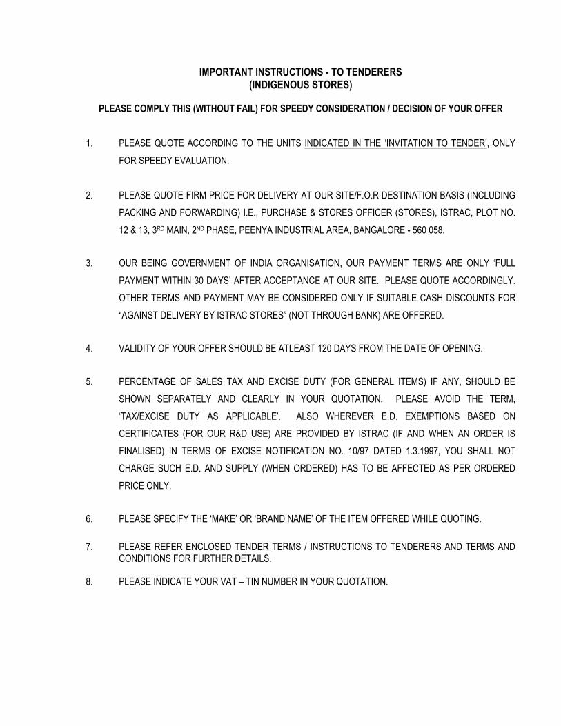
IMPORTANT INSTRUCTIONS - TO TENDERERS (INDIGENOUS STORES)
PLEASE COMPLY THIS (WITHOUT FAIL) FOR SPEEDY CONSIDERATION / DECISION OF YOUR OFFER
1. PLEASE QUOTE ACCORDING TO THE UNITS INDICATED IN THE ‘INVITATION TO TENDER’, ONLY
FOR SPEEDY EVALUATION.
2. PLEASE QUOTE FIRM PRICE FOR DELIVERY AT OUR SITE/F.O.R DESTINATION BASIS (INCLUDING
PACKING AND FORWARDING) I.E., PURCHASE & STORES OFFICER (STORES), ISTRAC, PLOT NO.
12 & 13, 3RD MAIN, 2ND PHASE, PEENYA INDUSTRIAL AREA, BANGALORE - 560 058.
3. OUR BEING GOVERNMENT OF INDIA ORGANISATION, OUR PAYMENT TERMS ARE ONLY ‘FULL
PAYMENT WITHIN 30 DAYS’ AFTER ACCEPTANCE AT OUR SITE. PLEASE QUOTE ACCORDINGLY.
OTHER TERMS AND PAYMENT MAY BE CONSIDERED ONLY IF SUITABLE CASH DISCOUNTS FOR
“AGAINST DELIVERY BY ISTRAC STORES” (NOT THROUGH BANK) ARE OFFERED.
4. VALIDITY OF YOUR OFFER SHOULD BE ATLEAST 120 DAYS FROM THE DATE OF OPENING.
5. PERCENTAGE OF SALES TAX AND EXCISE DUTY (FOR GENERAL ITEMS) IF ANY, SHOULD BE
SHOWN SEPARATELY AND CLEARLY IN YOUR QUOTATION. PLEASE AVOID THE TERM,
‘TAX/EXCISE DUTY AS APPLICABLE’. ALSO WHEREVER E.D. EXEMPTIONS BASED ON
CERTIFICATES (FOR OUR R&D USE) ARE PROVIDED BY ISTRAC (IF AND WHEN AN ORDER IS
FINALISED) IN TERMS OF EXCISE NOTIFICATION NO. 10/97 DATED 1.3.1997, YOU SHALL NOT
CHARGE SUCH E.D. AND SUPPLY (WHEN ORDERED) HAS TO BE AFFECTED AS PER ORDERED
PRICE ONLY.
6. PLEASE SPECIFY THE ‘MAKE’ OR ‘BRAND NAME’ OF THE ITEM OFFERED WHILE QUOTING.
7. PLEASE REFER ENCLOSED TENDER TERMS / INSTRUCTIONS TO TENDERERS AND TERMS AND CONDITIONS FOR FURTHER DETAILS.
8. PLEASE INDICATE YOUR VAT – TIN NUMBER IN YOUR QUOTATION.
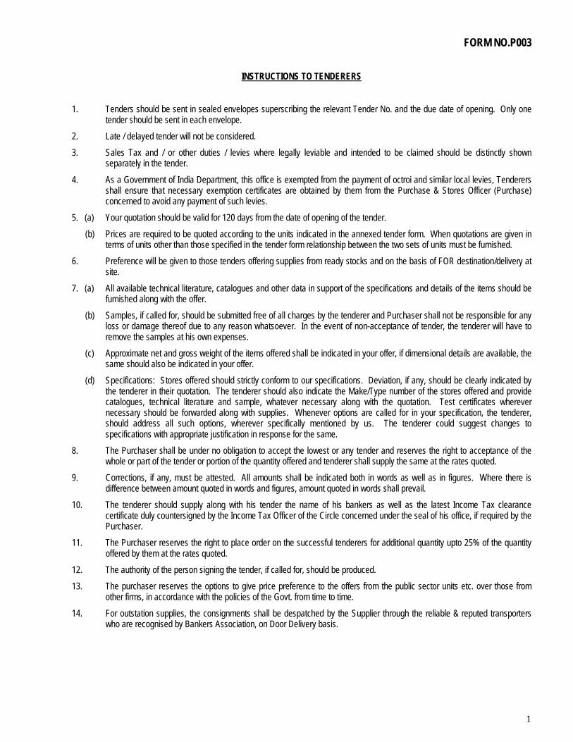
1
FORM NO.P003
INSTRUCTIONS TO TENDERERS
1. Tenders should be sent in sealed envelopes superscribing the relevant Tender No. and the due date of opening. Only one tender should be sent in each envelope.
2. Late / delayed tender will not be considered.
3. Sales Tax and / or other duties / levies where legally leviable and intended to be claimed should be distinctly shown separately in the tender.
4. As a Government of India Department, this office is exempted from the payment of octroi and similar local levies, Tenderers shall ensure that necessary exemption certificates are obtained by them from the Purchase & Stores Officer (Purchase) concerned to avoid any payment of such levies.
5. (a) Your quotation should be valid for 120 days from the date of opening of the tender.
(b) Prices are required to be quoted according to the units indicated in the annexed tender form. When quotations are given in terms of units other than those specified in the tender form relationship between the two sets of units must be furnished.
6. Preference will be given to those tenders offering supplies from ready stocks and on the basis of FOR destination/delivery at site.
7. (a) All available technical literature, catalogues and other data in support of the specifications and details of the items should be furnished along with the offer.
(b) Samples, if called for, should be submitted free of all charges by the tenderer and Purchaser shall not be responsible for any loss or damage thereof due to any reason whatsoever. In the event of non-acceptance of tender, the tenderer will have to remove the samples at his own expenses.
(c) Approximate net and gross weight of the items offered shall be indicated in your offer, if dimensional details are available, the same should also be indicated in your offer.
(d) Specifications: Stores offered should strictly conform to our specifications. Deviation, if any, should be clearly indicated by the tenderer in their quotation. The tenderer should also indicate the Make/Type number of the stores offered and provide catalogues, technical literature and sample, whatever necessary along with the quotation. Test certificates wherever necessary should be forwarded along with supplies. Whenever options are called for in your specification, the tenderer, should address all such options, wherever specifically mentioned by us. The tenderer could suggest changes to specifications with appropriate justification in response for the same.
8. The Purchaser shall be under no obligation to accept the lowest or any tender and reserves the right to acceptance of the whole or part of the tender or portion of the quantity offered and tenderer shall supply the same at the rates quoted.
9. Corrections, if any, must be attested. All amounts shall be indicated both in words as well as in figures. Where there is difference between amount quoted in words and figures, amount quoted in words shall prevail.
10. The tenderer should supply along with his tender the name of his bankers as well as the latest Income Tax clearance certificate duly countersigned by the Income Tax Officer of the Circle concerned under the seal of his office, if required by the Purchaser.
11. The Purchaser reserves the right to place order on the successful tenderers for additional quantity upto 25% of the quantity offered by them at the rates quoted.
12. The authority of the person signing the tender, if called for, should be produced.
13. The purchaser reserves the options to give price preference to the offers from the public sector units etc. over those from other firms, in accordance with the policies of the Govt. from time to time.
14. For outstation supplies, the consignments shall be despatched by the Supplier through the reliable & reputed transporters who are recognised by Bankers Association, on Door Delivery basis.
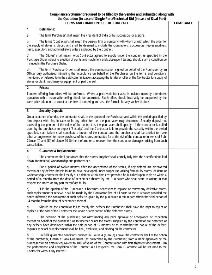
2
Compliance Statement required to be filled by the Vendor and submitted along with
the Quotation (in case of Single Part)/Technical Bid (in case of Dual Part) TERMS AND CONDITIONS OF THE CONTRACT COMPLIANCE
1. Definitions: a) The term ‘Purchaser’ shall mean the President of India or his successors or assigns.
b) The terms ‘Contractor’ shall mean the person, firm or company with whom or with which the order for the supply of stores is placed and shall be deemed to include the Contractor’s Successors, representatives, heirs, executors and administrators unless excluded by the Contract.
c) The ‘Stores’ shall mean, what Contractor agrees to supply under the contract as specified in the Purchase Order including erection of plants and machinery and subsequent testing, should such a condition be included in the Purchase Order.
d) The term ‘Purchase Order’ shall mean, the communication signed on behalf of the Purchaser by an Officer duly authorised intimating the acceptance on behalf of the Purchaser on the terms and conditions mentioned or referred to in the said communication accepting the tender or offer of the Contractor for supply of stores or plant, machinery or equipment or part thereof.
2. Prices: Tenders offering firm prices will be preferred. Where a price variation clause is insisted upon by a tenderer, quotation with a reasonable ceiling should be submitted. Such offers should invariably be supported by the base price taken into account at the time of tendering and also the formula for any such variations.
3. Security Deposit: On acceptance of tender, the contractor shall, at the option of the Purchaser and within the period specified by him deposit with him, in case or in any other form as the purchaser may determine, Security deposit not exceeding ten percent of the value of the contract as the purchaser shall specify. If the contractor is called upon by the purchaser to deposit ‘Security’ and the Contractor fails to provide the security within the period specified, such failure shall constitute a breach of the contract and the purchaser shall be entitled to make other arrangements for the re-purchase of the stores contracted for at the risk of the contractor in terms of Sub-Clause (II) and (III) of clause 10 (b) here-of and or to recover from the contractor damages arising from such cancellation.
4. Guarantee & Replacement: a) The contractor shall guarantee that the stores supplied shall comply fully with the specifications laid down, for material, workmanship and performance.
b) For a period of twelve months after the acceptance of the stores, if any defects are discovered therein or any defects therein found to have developed under proper use arising from faulty stores, designs or workmanship, contractor shall rectify such defects at his own cost provided he is called upon to do so within a period of14 months from the date of acceptance thereof by the Purchaser who shall state in writing in that respect the stores or any part thereof are faulty.
c) If in the opinion of the Purchaser, it becomes necessary to replace or renew any defective stores such replacement or renewal shall be made by the Contractor free of all costs to the Purchaser provided the notice informing the contractor of such defect is given by the purchaser in this regard within the said period of 14 months from the date of acceptance thereof.
d) Should be the contractor fail to rectify the defects the Purchaser shall have the right to reject or replace at the cost of the Contractor the whole or any portion of the defective stores.
e) The decision of the purchaser, not withstanding any prior approval or acceptance or inspection thereof on behalf of the purchaser, as to whether or not the stores supplied by the contractor are defective or any defects have developed within the said period of 12 months or as to whether the nature of the defects requires renewal or replacement shall be final, exclusive, and binding on the contractor.
f) To fulfill guarantee conditions outlines in Clause 4 (a) to (e) above, the contractor shall at the option of the purchaser, furnish a Bank Guarantee (as prescribed by the Purchaser) from a Bank approved by the purchaser for an amount equivalent to 10% of value of the Contract along with first shipment documents. On the performance and completion of the Contract in all respects, the Bank Guarantee will be returned to the Contractor without any interest.
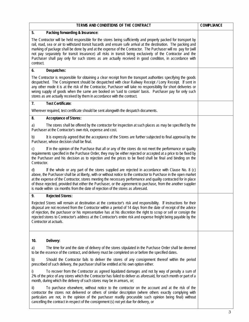
3
TERMS AND CONDITIONS OF THE CONTRACT COMPLIANCE
5. Packing forwarding & Insurance: The Contractor will be held responsible for the stores being sufficiently and properly packed for transport by rail, road, sea or air to withstand transit hazards and ensure safe arrival at the destination. The packing and marking of package shall be done by and at the expense of the Contractor. The Purchaser will no pay for (will not pay separately for transit insurance) all risks in transit being exclusively of the Contractor and the Purchaser shall pay only for such stores as are actually received in good condition, in accordance with contract.
6. Despatches: The Contractor is responsible for obtaining a clear receipt from the transport authorities specifying the goods despatched. The Consignment should be despatched with clear Railway Receipt / Lorry Receipt. If sent in any other mode it is at the risk of the Contractor, Purchaser will take no responsibility for short deliveries or wrong supply of goods when the same are booked on ‘said to contain’ basis. Purchaser pay for only such stores as are actually received by them in accordance with the contract.
7. Test Certificate: Wherever required, test certificate should be sent alongwith the despatch documents.
8. Acceptance of Stores: a) The stores shall be offered by the contractor for inspection at such places as may be specified by the Purchaser at the Contractor’s own risk, expense and cost.
b) It is expressly agreed that the acceptance of the Stores are further subjected to final approval by the Purchaser, whose decision shall be final.
c) If in the opinion of the Purchase that all or any of the stores do not meet the performance or quality requirements specified in the Purchase Order, they may be either rejected or accepted at a price to be fixed by the Purchaser and his decision as to rejection and the prices to be fixed shall be final and binding on the Contractor.
d) If the whole or any part of the stores supplied are rejected in accordance with Clause No. 8 (c) above, the Purchaser shall be at liberty, with or without notice to the contractor to Purchase in the open market at the expense of the Contractor, stores meeting the necessary performance and quality contracted for in place of those rejected, provided that either the Purchaser, or the agreement to purchase, from the another supplier is made within six months from the date of rejection of the stores as aforesaid.
9. Rejected Stores: Rejected Stores will remain at destination at the contractor’s risk and responsibility. If instructions for their disposal are not received from the Contractor within a period of 14 days from the date of receipt of the advice of rejection, the purchaser or his representative has at his discretion the right to scrap or sell or consign the rejected stores to Contractor’s address at the Contractor’s entire risk and expense freight being payable by the Contractor at actuals.
10. Delivery: a) The time for and the date of delivery of the stores stipulated in the Purchase Order shall be deemed to be the essence of the contract, and delivery must be completed on or before the specified dates.
b) Should the Contractor fails to deliver the stores of any consignment thereof within the period prescribed of such delivery, the purchaser shall be entitled at his own option either.
i) To recover from the Contractor as agreed liquidated damages and not by way of penalty a sum of 2% of the price of any stores which the Contractor has failed to deliver as aforesaid, for each month or part of a month, during which the delivery of such stores may be in arrears, or;
ii) To purchase elsewhere, without notice to the contractor on the account and at the risk of the contractor the stores not delivered or others of similar description (where others exactly complying with particulars are not, in the opinion of the purchaser readily procurable such opinion being final) without cancelling the contract in respect of the consignment (s) not yet due for delivery, or

4
TERMS AND CONDITIONS OF THE CONTRACT COMPLIANCE
iii) To cancel the contract or portion thereof, and if so desired to purchase or authorise of stores not so delivered or others of similar description (where others exactly complying with the particulars are not, in the opinion of the readily procurable; such opinion final) at the risk and cost of Contractor. In the event of action being taken under sub-clause (ii) & (iii) of clause 10 above the Contractor shall be liable for any loss which the purchaser may sustain on that account, provided that the repurchase, or if there is an agreement to repurchase then such agreement is made within six months from the date of such failure. But the contractor shall not be entitled to any gain on such repurchase made against default. The manner and method of such repurchase shall be at the discretion of the Purchaser, whose decision shall be final. It shall not be necessary for the Purchaser to serve a notice of such repurchase on the defaulting Contractor. This right shall be without prejudice to the right of the Purchaser to recover damages for breach of contract by the Contractor.
11. Extension of time: As soon as it is apparent that contract dates cannot be adhered to, an application shall be sent by the Contractor to the Purchaser. If failure on the part of the Contractor to deliver the stores in proper times shall have arisen from any cause which the Purchaser may admit as responsible ground for an extension of the time (and his decision shall be final) he may allow such additional time as he considered it to be justified by circumstances of the case without prejudice to the Purchaser’s rights to recover liquidated damages under clause 10 here-of.
12. Erection of Plant & Machinery: Wherever erection of a Plant or Machinery is the responsibility of the Contractor as per the terms of the Contract and in case the Contractor fails to carry out the erection as and when called upon to do so within the period specified by the Purchaser, the Purchaser shall have the right to get the erection done through any source of his choice. In such an event, the contractor shall be liable to bear any additional expenditure that the Purchaser is liable to incur towards erection. The contractor shall however, not be entitled to any gain due to such an action by the Purchaser.
13. Payment: 100% Payment through RTGS within 30 days after receipt and acceptance of items at our Stores.
14. Recovery of sums due: Whenever any claim for the payment of whether liquidated or not, moneys arises out of or under this contract against the Contractor, the Purchaser shall be entitled to recover such sum by appropriating in part or whole, the security deposited by the Contractor, if a security is taken against the Contract.
In the event of the security being insufficient or if no security has been taken from the contractor, then the balance or the total sum recoverable, as the case may be shall be deducted from any such then due or which at any time thereafter may become due to the Contractor under this or any other contract with the Purchaser. Should this sum be not sufficient to cover the full amount recoverable, the contractor shall pay to the Purchaser on demand the remaining balance due. Similarly if the Purchaser has or makes any claims, whether liquidated or not, against the contractor under any other contract with the Purchaser, the payment of all moneys payable under the contract to the contractor including the security deposit shall be with-held till such claims of the Purchaser are finally adjudicated upon and paid by the Contractor.
15. Indemnity: The Contractor shall warrant and be deemed to have warranted that all stores supplied against this contract are free and clean of infringement of any Patent, copyright or trade mark, and shall at all times indemnify the Purchaser against all claims which may be made in respect of the stores or infringement of any right protected by patent, Registration or design or Trade Mark and shall take all risk of accidents of damage which may cause a failure of the supply from whatever cause arising and entire responsibility for sufficiency of all the means used by him for the fulfillment of the Contract.
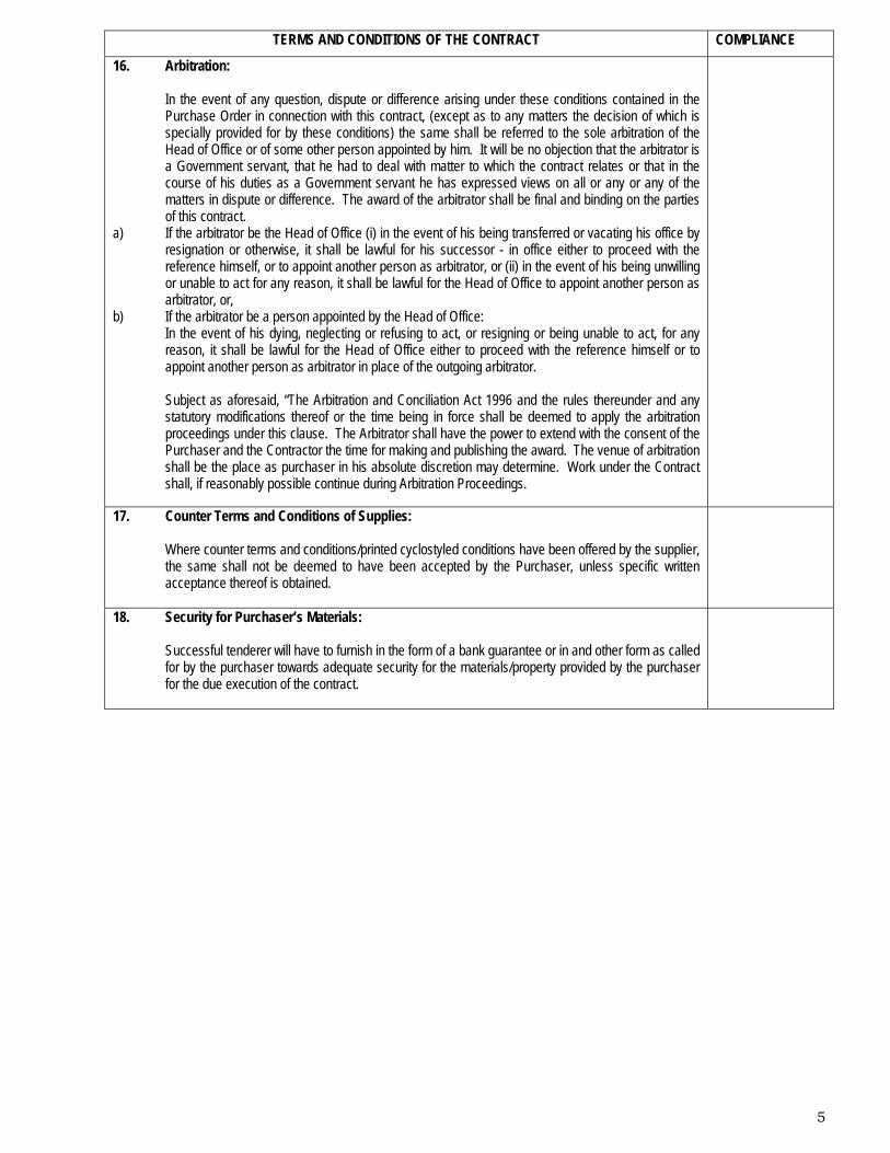
5
TERMS AND CONDITIONS OF THE CONTRACT COMPLIANCE
16. Arbitration:
In the event of any question, dispute or difference arising under these conditions contained in the Purchase Order in connection with this contract, (except as to any matters the decision of which is specially provided for by these conditions) the same shall be referred to the sole arbitration of the Head of Office or of some other person appointed by him. It will be no objection that the arbitrator is a Government servant, that he had to deal with matter to which the contract relates or that in the course of his duties as a Government servant he has expressed views on all or any or any of the matters in dispute or difference. The award of the arbitrator shall be final and binding on the parties of this contract.
a) If the arbitrator be the Head of Office (i) in the event of his being transferred or vacating his office by resignation or otherwise, it shall be lawful for his successor - in office either to proceed with the reference himself, or to appoint another person as arbitrator, or (ii) in the event of his being unwilling or unable to act for any reason, it shall be lawful for the Head of Office to appoint another person as arbitrator, or,
b) If the arbitrator be a person appointed by the Head of Office: In the event of his dying, neglecting or refusing to act, or resigning or being unable to act, for any reason, it shall be lawful for the Head of Office either to proceed with the reference himself or to appoint another person as arbitrator in place of the outgoing arbitrator. Subject as aforesaid, “The Arbitration and Conciliation Act 1996 and the rules thereunder and any statutory modifications thereof or the time being in force shall be deemed to apply the arbitration proceedings under this clause. The Arbitrator shall have the power to extend with the consent of the Purchaser and the Contractor the time for making and publishing the award. The venue of arbitration shall be the place as purchaser in his absolute discretion may determine. Work under the Contract shall, if reasonably possible continue during Arbitration Proceedings.
17. Counter Terms and Conditions of Supplies:
Where counter terms and conditions/printed cyclostyled conditions have been offered by the supplier, the same shall not be deemed to have been accepted by the Purchaser, unless specific written acceptance thereof is obtained.
18. Security for Purchaser’s Materials:
Successful tenderer will have to furnish in the form of a bank guarantee or in and other form as called for by the purchaser towards adequate security for the materials/property provided by the purchaser for the due execution of the contract.