telemetry, tracking, communications, command and data...
TRANSCRIPT
Telemetry, Tracking, Communications, Commandand Data Handling
Cengiz AkinliMatthew Gamache
Matthew RoseAndrew RostJames SalesJames Tang
November 18, 2004
Contents
List of Figures ii
List of Tables iii
1 Introduction 11.1 Communications . . . . . . . . . . . . . . . . . . . . . . . . . . . . . 2
1.1.1 Receiver and Transmitter Selection . . . . . . . . . . . . . . . 21.1.2 Antenna Selection . . . . . . . . . . . . . . . . . . . . . . . . . 41.1.3 Frequency Selection . . . . . . . . . . . . . . . . . . . . . . . . 51.1.4 Link Budget . . . . . . . . . . . . . . . . . . . . . . . . . . . . 7
1.2 Telemetry, Computer, Command and Data Handling . . . . . . . . . 81.2.1 Computer States and State Diagrams . . . . . . . . . . . . . . 81.2.2 Interface Design and Architecture Selection . . . . . . . . . . 81.2.3 Software . . . . . . . . . . . . . . . . . . . . . . . . . . . . . . 101.2.4 Flow Diagrams . . . . . . . . . . . . . . . . . . . . . . . . . . 111.2.5 Operating Budget Considerations . . . . . . . . . . . . . . . . 111.2.6 Modeling and Analysis . . . . . . . . . . . . . . . . . . . . . . 12
1.3 Conclusion . . . . . . . . . . . . . . . . . . . . . . . . . . . . . . . . . 14
2 Modeling and Analysis 152.1 Communications . . . . . . . . . . . . . . . . . . . . . . . . . . . . . 15
2.1.1 Effect of Other Subsystems on Communications . . . . . . . . 162.1.2 Communication System Modeling . . . . . . . . . . . . . . . . 162.1.3 Sizing of Communications System . . . . . . . . . . . . . . . . 232.1.4 Interactions of Subsystems . . . . . . . . . . . . . . . . . . . . 24
2.2 Spacecraft Command System . . . . . . . . . . . . . . . . . . . . . . 242.2.1 Receiver/Demodulator . . . . . . . . . . . . . . . . . . . . . . 252.2.2 Command Decoder . . . . . . . . . . . . . . . . . . . . . . . . 252.2.3 Command Logic and Handling . . . . . . . . . . . . . . . . . . 292.2.4 Interface Circuitry . . . . . . . . . . . . . . . . . . . . . . . . 32
2.3 Conclusion . . . . . . . . . . . . . . . . . . . . . . . . . . . . . . . . . 33
1
3 Examples 343.1 Communications . . . . . . . . . . . . . . . . . . . . . . . . . . . . . 34
3.1.1 Communications Components . . . . . . . . . . . . . . . . . . 343.1.2 Link Budget Examples . . . . . . . . . . . . . . . . . . . . . . 37
3.2 Command Handling and Execution . . . . . . . . . . . . . . . . . . . 393.3 System Hardware . . . . . . . . . . . . . . . . . . . . . . . . . . . . . 43
3.3.1 PC104 . . . . . . . . . . . . . . . . . . . . . . . . . . . . . . . 433.3.2 Radiation-Hardened Computer Systems . . . . . . . . . . . . . 443.3.3 Conclusion . . . . . . . . . . . . . . . . . . . . . . . . . . . . . 45
3.4 Demodulation and Amplification . . . . . . . . . . . . . . . . . . . . 463.4.1 Low- and High- Pass Filters . . . . . . . . . . . . . . . . . . . 463.4.2 Band-pass Filters . . . . . . . . . . . . . . . . . . . . . . . . . 473.4.3 Band-reject Filters . . . . . . . . . . . . . . . . . . . . . . . . 473.4.4 Superheterodyne Filters . . . . . . . . . . . . . . . . . . . . . 483.4.5 Mechanical Filters . . . . . . . . . . . . . . . . . . . . . . . . 483.4.6 Conclusion . . . . . . . . . . . . . . . . . . . . . . . . . . . . . 48
3.5 Conclusion . . . . . . . . . . . . . . . . . . . . . . . . . . . . . . . . . 48
4 Summary and Conclusions 504.1 Communications . . . . . . . . . . . . . . . . . . . . . . . . . . . . . 50
4.1.1 Summary . . . . . . . . . . . . . . . . . . . . . . . . . . . . . 504.1.2 Future Research . . . . . . . . . . . . . . . . . . . . . . . . . . 514.1.3 Conclusion . . . . . . . . . . . . . . . . . . . . . . . . . . . . . 52
4.2 Command and Data Handling . . . . . . . . . . . . . . . . . . . . . . 524.2.1 Reliability and Robustness . . . . . . . . . . . . . . . . . . . . 524.2.2 Security . . . . . . . . . . . . . . . . . . . . . . . . . . . . . . 534.2.3 Other Issues . . . . . . . . . . . . . . . . . . . . . . . . . . . . 534.2.4 Existing Systems . . . . . . . . . . . . . . . . . . . . . . . . . 544.2.5 Future Research . . . . . . . . . . . . . . . . . . . . . . . . . . 54
4.3 System Hardware . . . . . . . . . . . . . . . . . . . . . . . . . . . . . 544.3.1 Architecture Selection . . . . . . . . . . . . . . . . . . . . . . 554.3.2 Interface Circuitry . . . . . . . . . . . . . . . . . . . . . . . . 554.3.3 Commercial Off The Shelf Computers . . . . . . . . . . . . . . 564.3.4 Future Research and Recommendations . . . . . . . . . . . . . 564.3.5 Conclusion . . . . . . . . . . . . . . . . . . . . . . . . . . . . . 57
4.4 Conclusion . . . . . . . . . . . . . . . . . . . . . . . . . . . . . . . . . 57
Bibliography 59
A Tables 60
i
List of Figures
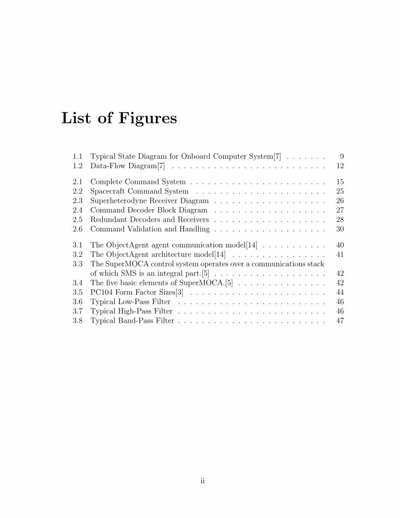
1.1 Typical State Diagram for Onboard Computer System[7] . . . . . . . 91.2 Data-Flow Diagram[7] . . . . . . . . . . . . . . . . . . . . . . . . . . 12
2.1 Complete Command System . . . . . . . . . . . . . . . . . . . . . . . 152.2 Spacecraft Command System . . . . . . . . . . . . . . . . . . . . . . 252.3 Superheterodyne Receiver Diagram . . . . . . . . . . . . . . . . . . . 262.4 Command Decoder Block Diagram . . . . . . . . . . . . . . . . . . . 272.5 Redundant Decoders and Receivers . . . . . . . . . . . . . . . . . . . 282.6 Command Validation and Handling . . . . . . . . . . . . . . . . . . . 30
3.1 The ObjectAgent agent communication model[14] . . . . . . . . . . . 403.2 The ObjectAgent architecture model[14] . . . . . . . . . . . . . . . . 413.3 The SuperMOCA control system operates over a communications stack
of which SMS is an integral part.[5] . . . . . . . . . . . . . . . . . . . 423.4 The five basic elements of SuperMOCA.[5] . . . . . . . . . . . . . . . 423.5 PC104 Form Factor Sizes[3] . . . . . . . . . . . . . . . . . . . . . . . 443.6 Typical Low-Pass Filter . . . . . . . . . . . . . . . . . . . . . . . . . 463.7 Typical High-Pass Filter . . . . . . . . . . . . . . . . . . . . . . . . . 463.8 Typical Band-Pass Filter . . . . . . . . . . . . . . . . . . . . . . . . . 47
ii
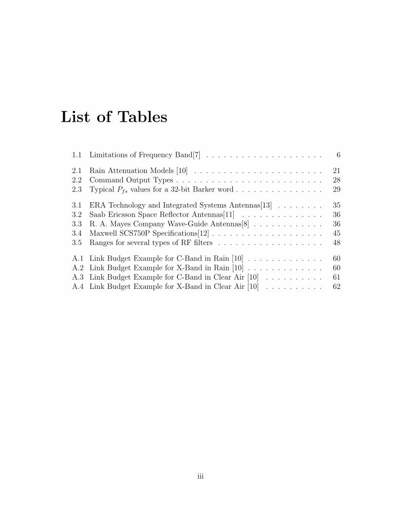
List of Tables
1.1 Limitations of Frequency Band[7] . . . . . . . . . . . . . . . . . . . . 6
2.1 Rain Attenuation Models [10] . . . . . . . . . . . . . . . . . . . . . . 212.2 Command Output Types . . . . . . . . . . . . . . . . . . . . . . . . . 282.3 Typical Pfs values for a 32-bit Barker word . . . . . . . . . . . . . . . 29
3.1 ERA Technology and Integrated Systems Antennas[13] . . . . . . . . 353.2 Saab Ericsson Space Reflector Antennas[11] . . . . . . . . . . . . . . 363.3 R. A. Mayes Company Wave-Guide Antennas[8] . . . . . . . . . . . . 363.4 Maxwell SCS750P Specifications[12] . . . . . . . . . . . . . . . . . . . 453.5 Ranges for several types of RF filters . . . . . . . . . . . . . . . . . . 48
A.1 Link Budget Example for C-Band in Rain [10] . . . . . . . . . . . . . 60A.2 Link Budget Example for X-Band in Rain [10] . . . . . . . . . . . . . 60A.3 Link Budget Example for C-Band in Clear Air [10] . . . . . . . . . . 61A.4 Link Budget Example for X-Band in Clear Air [10] . . . . . . . . . . 62
iii
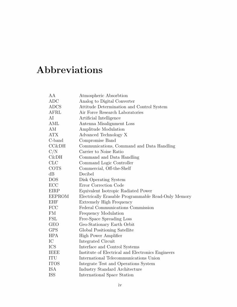
Abbreviations
AA Atmospheric AbsorbtionADC Analog to Digital ConverterADCS Attitude Determination and Control SystemAFRL Air Force Research LaboratoriesAI Artificial IntelligenceAML Antenna Misalignment LossAM Amplitude ModulationATX Advanced Technology XC-band Compromise BandCC&DH Communications, Command and Data HandlingC/N Carrier to Noise RatioC&DH Command and Data HandlingCLC Command Logic ControllerCOTS Commercial, Off-the-ShelfdB DecibelDOS Disk Operating SystemECC Error Correction CodeEIRP Equivalent Isotropic Radiated PowerEEPROM Electrically Erasable Programmable Read-Only MemoryEHF Extremely High FrequencyFCC Federal Communications CommissionFM Frequency ModulationFSL Free-Space Spreading LossGEO Geo-Stationary Earth OrbitGPS Global Positioning SatelliteHPA High Power AmplifierIC Integrated CircuitICS Interface and Control SystemsIEEE Institute of Electrical and Electronics EngineersITU International Telecommunications UnionITOS Integrate Test and Operations SystemISA Industry Standard ArchitectureISS International Space Station
iv
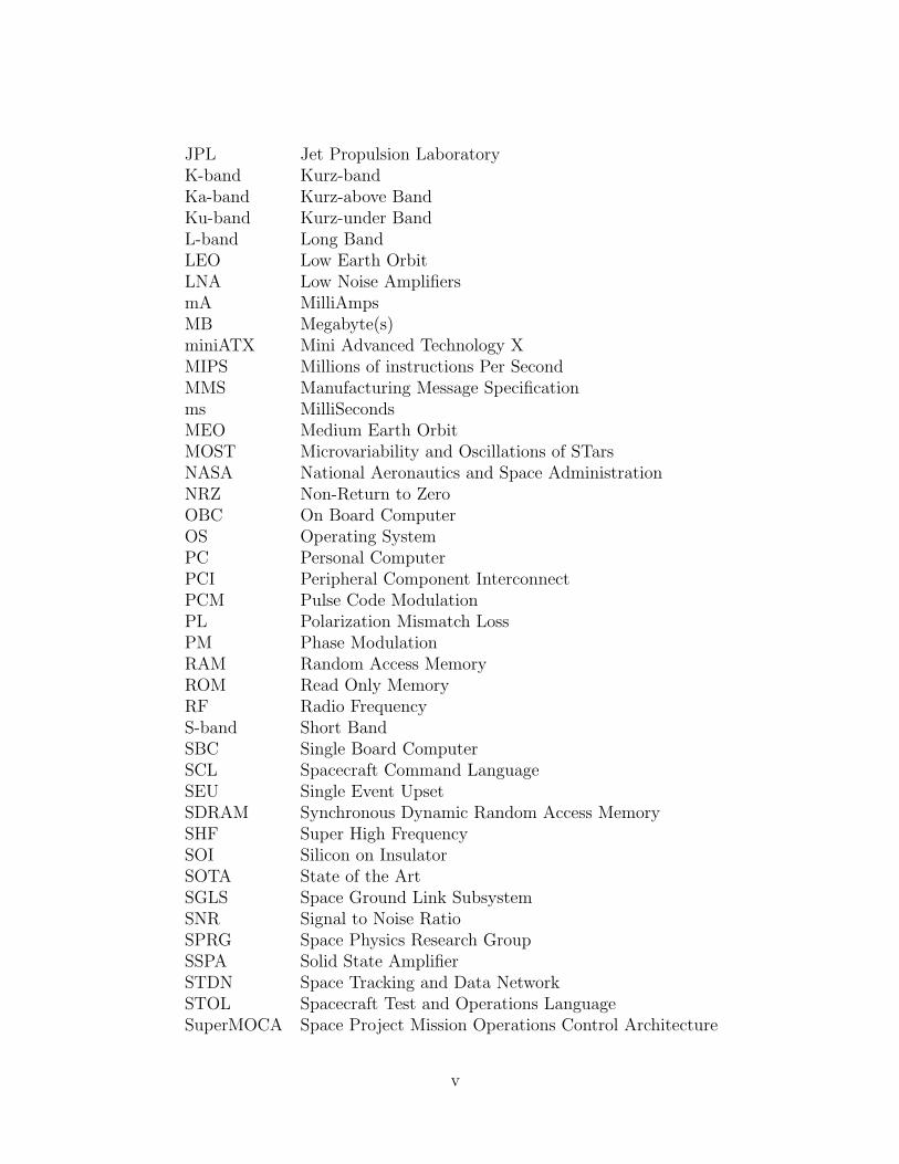
JPL Jet Propulsion LaboratoryK-band Kurz-bandKa-band Kurz-above BandKu-band Kurz-under BandL-band Long BandLEO Low Earth OrbitLNA Low Noise AmplifiersmA MilliAmpsMB Megabyte(s)miniATX Mini Advanced Technology XMIPS Millions of instructions Per SecondMMS Manufacturing Message Specificationms MilliSecondsMEO Medium Earth OrbitMOST Microvariability and Oscillations of STarsNASA National Aeronautics and Space AdministrationNRZ Non-Return to ZeroOBC On Board ComputerOS Operating SystemPC Personal ComputerPCI Peripheral Component InterconnectPCM Pulse Code ModulationPL Polarization Mismatch LossPM Phase ModulationRAM Random Access MemoryROM Read Only MemoryRF Radio FrequencyS-band Short BandSBC Single Board ComputerSCL Spacecraft Command LanguageSEU Single Event UpsetSDRAM Synchronous Dynamic Random Access MemorySHF Super High FrequencySOI Silicon on InsulatorSOTA State of the ArtSGLS Space Ground Link SubsystemSNR Signal to Noise RatioSPRG Space Physics Research GroupSSPA Solid State AmplifierSTDN Space Tracking and Data NetworkSTOL Spacecraft Test and Operations LanguageSuperMOCA Space Project Mission Operations Control Architecture
v
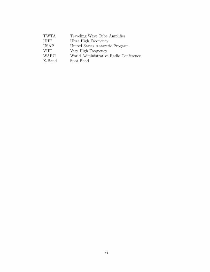
TWTA Traveling Wave Tube AmplifierUHF Ultra High FrequencyUSAP United States Antarctic ProgramVHF Very High FrequencyWARC World Administrative Radio ConferenceX-Band Spot Band
vi
Symbols
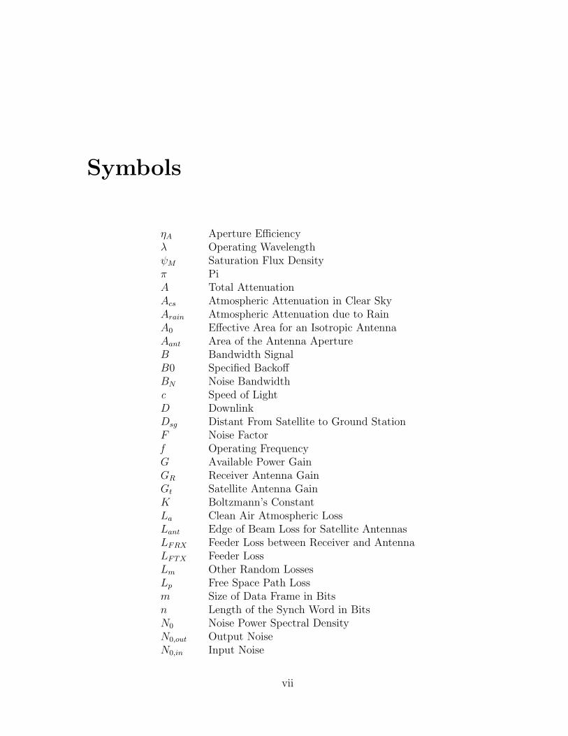
ηA Aperture Efficiencyλ Operating WavelengthψM Saturation Flux Densityπ PiA Total AttenuationAcs Atmospheric Attenuation in Clear SkyArain Atmospheric Attenuation due to RainA0 Effective Area for an Isotropic AntennaAant Area of the Antenna ApertureB Bandwidth SignalB0 Specified BackoffBN Noise Bandwidthc Speed of LightD DownlinkDsg Distant From Satellite to Ground StationF Noise Factorf Operating FrequencyG Available Power GainGR Receiver Antenna GainGt Satellite Antenna GainK Boltzmann’s ConstantLa Clean Air Atmospheric LossLant Edge of Beam Loss for Satellite AntennasLFRX Feeder Loss between Receiver and AntennaLFTX Feeder LossLm Other Random LossesLp Free Space Path Lossm Size of Data Frame in Bitsn Length of the Synch Word in BitsN0 Noise Power Spectral DensityN0,out Output NoiseN0,in Input Noise
vii
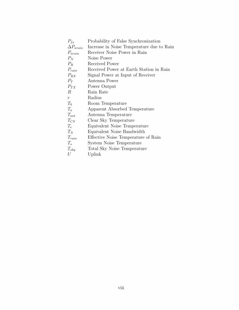
Pfs Probability of False Synchronization∆Pnrain Increase in Noise Temperature due to RainPnrain Receiver Noise Power in RainPN Noise PowerPR Received PowerPrain Received Power at Earth Station in RainPRX Signal Power at Input of ReceiverPT Antenna PowerPTX Power OutputR Rain Rater RadiusT0 Room TemperatureTa Apparent Absorbed TemperatureTant Antenna TemperatureTCS Clear Sky TemperatureTe Equivalent Noise TemperatureTN Equivalent Noise BandwidthTrain Effective Noise Temperature of RainTs System Noise TemperatureTsky Total Sky Noise TemperatureU Uplink
viii
Chapter 1
Introduction
The basic function of all but the simplest spacecraft requires extensive contact withground stations for control, command, communication, and data return, and sufficientcomputer processing power to run all spacecraft subsystems with, in many cases, ahigh degree of autonomy.
A spacecraft communication system handles all data sent and received by thespacecraft, including spacecraft bus commands, and payload operations. The systemincorporates a transmitter and a receiver that are the sole point of passage for dataentering or leaving the spacecraft. Thus payload and bus operations data are bothhandled by this system.
The driving concerns in the design and implementation of spacecraft communi-cations systems are access, radio frequency selection, and data characteristics. Inconsidering communication access, the selection of ground station location, visibil-ity windows for those candidate locations for a given spacecraft orbit, and antennaand transmitter power selection are key concerns. In selecting the radio frequency,issues such as the transmitter power and receiver sensitivity requirements for givenfrequencies and the power required to overcome atmospheric conditions must be con-sidered. Additionally, permission to use a particular frequency must be applied forand granted by the appropriate regulatory agency. Finally, antenna and transmitterpower required to attain the bandwidth and maximum error level allowed by thecharacteristics of the data to be communicated are determined.
The command and data handling system (C&DH) receives all commands anddata for both bus and payload operations from the communications system. Theintegration of payload data with bus data into the data stream bound for the com-munications system and the disintegration of the incoming data stream into individualdata streams bound for the bus and payload are the primary roles of the C&DH sys-tem. The final major function is the handling of bus commands by directing themto the appropriate subsystem or executing them directly. The handling of payloadcommands would generally not be done by the C&DH system, but would instead bepassed, fully encapsulated, directly to the payload.
1
In selecting, or more usually, designing a command and data handling system, con-cerns vary somewhat based on the spacecraft payload. Science payloads may makeextensive use of C&DH subsystems in terms of high bandwidth data streams andeven data storage and computation. Payloads often require continuous communica-tion with ground stations, precise attitude control, and other services which togethernecessitate a close interoperation of C&DH systems with the payload. Selection is apredominately linear process, requiring the advance preparation of commands to beexecuted by the bus and payload, telemetry to be sent and received by all spacecraftsubsystems, determination of time criticality of subsystem functions, and finally de-termining the parameters of a system that will address all of these issues satisfactorily.
In CC&DH, there are two major functional divisions. The communication sub-system controls the data transfer between the spacecraft and a station on Earth. TheC&DH subsystem covers the control of data flow internally as well as the disassemblyof commands to individual sections of the spacecraft. The C&DH subsystem directsthe rest of the spacecraft in how to accomplish the mission. Both of these combinedencompass the whole of the CC&DH system.
1.1 Communications
The communications subsystem is an important aspect to consider in the designof satellites. The communications subsystem deals with the data transfer from thesatellite to a ground station on Earth. This transfer can be made either by linkingthrough radio waves to a ground station directly or by linking to other satellites andthen finally to a ground station on Earth. The main types of data that are transferredbetween the satellite and the ground station are the updated command controls for thespacecraft, the collected mission data from the spacecraft and the operational healthstatus of the spacecraft. The main components in the communications subsystem arethe receivers, transmitters, and antennas. The systems in place in the communicationssystems are set up to be redundant. Redundancy is needed on satellites becausesystem failure makes the satellite ineffective.
1.1.1 Receiver and Transmitter Selection
The size, type and gain of the receiver, transmitters and antennas used depend mainlyon the type of mission the spacecraft is designed to accomplish. There are two maintypes of missions dealing with communications: near Earth communication and long-range data relay. The receivers and transmitters consist of several parts. The keycomponents in receivers and transmitters are amplifiers, filters and demodulators.The amplifiers and filters are combined into a single unit.
2
Transponder
A transponder consists of several parts. These parts include a band-pass filter, adown converter, and an output amplifier. The band-pass filter is used to select theparticular channel’s band of frequencies. The down converter is used to change thefrequency from 6 GHz at the input to 4 GHz at the output. Most communicationsystems have multiple transponders, usually 12 to 44 for a high-capacity satellite.The main bandwidths for the transponders are 36, 54, and 72 MHz. These narrowbandwidths are used in order to avoid intermodulation.
Amplifier
The signal that is received by the satellite’s antenna is passed through two low noiseamplifiers (LNA) and is recombined at the output. The use of two LNA is neededto provide redundancy. The low noise amplifiers are used in order to minimize theaddition of noise to the incoming signal.
The signals that are sent from a satellite require amplification in order to producea signal that can be received from Earth. Typically, the output power amplifierthat is used is a solid state amplifier (SSPA). If the satellite requires a high poweroutput, a traveling wave tube amplifier (TWTA) is used. Redundancy in the highpower amplifiers (HPA) is provided by including a backup TWTA or SSPA thatwill be activated in case of the primary’s failure. The least reliable part of anytransponder is the HPA. This reliability issue is resolved by providing a spare HPAin each transponder.
Modulation
The signal that is received is modulated in order to obtain several goals. These goalsinclude obtaining the required data rate, fitting the signal into the available radiofrequency (RF) bandwidth, and obtaining the required signal to noise ratio (SNR).There are several types of modulation that may be used. These types of modula-tions include amplitude modulation (AM), phase modulation (PM), and frequencymodulation (FM).
The type of modulation that is performed on the signal is determined by thedesired output. Amplitude modulation requires a higher SNR to attain a high per-formance but the performance degrades slowly as the SNR is reduced. The FM andPM degrade quickly as the SNR is decreased but can operate at lower RF SNR thanAM.
The modulation is performed on the amplified signals in order to attain the desiredoutput. The modulated signal is then transmitted to the command decoder andprocessor.
3
Noise
The noise of the system is an important aspect of the system to determine. In thecommunications subsystem, the need for a maximized carrier to noise ratio (C/N) isdesired. In order to achieve this goal, the amount of noise present in the system needsto be minimized. This minimization is needed because of the weak carrier signalsinvolved. A method of dealing with noise minimization is to allow only the desiredbandwidth to pass through the filter. This process of filtering all the bandwidthsblocks excess signals that may be a source of noise.
The performance of the receiving system is determined by comparing the totalthermal noise power against the signal demodulation. Thermal noise is produced byevery active and passive device involved in the communications system. The goalis to minimize the addition of noise from the satellite’s components. An additionalsource of noise to the signal is the atmospheric conditions that the carrier signal hasto travel through. The noises encountered throughout the system are simplified toa single term, the system noise temperature (Ts). Losses occur in the connectionbetween the antenna and receiver. These losses are part of the feeder loss. Theyoccur in the connecting waveguides, filters, and couplers. Similar losses will occurbetween the antenna and amplifier in the filters, waveguides, and couplers.
1.1.2 Antenna Selection
The main goal in antenna selection is determining the proper type and size of antennaneeded. In general, a larger antenna has a better gain and SNR than a smallerantenna. The main constraint on antenna sizing is the weight and power requirements.The main types of antenna are wire, horn, reflector and helical antennas.
Wire Antenna
Wire antennas provide omni-directional coverage that are used primarily duringlaunch and orbit insertion. They are primarily used when the main antenna havenot been deployed or properly positioned. The main frequencies for wire antennasare UHF and VHF.
Horn Antenna
Horn antennas are used when a wide beam has to be produced for global coverage.The main frequencies that are used with horn antennas are microwave frequencies.The gains that can be obtained from horn antenna are usually less then 23 dB andthe beamwidths are usually larger then 10 degrees.
4
Reflector Antenna
Reflective antennas usually contain at least one horn and provide a larger usable areathen a horn antenna alone. The basic shape of the reflector antenna is a paraboloid.The reflecting shape is based on a three-dimensional parabolic shape. It has a uniqueproperty of directing all incoming wave fronts perpendicular to its axis, in phase, to apoint focus. Reflective antennas are generally made of steel, aluminum, or fiberglasswith an embedded reflective foil.
Antenna Arrays
An antenna array is defined as being more than one antenna brought together toaccomplish a task. The antennas in the array will be brought together and drivenfrom a source of power at the same frequency. The resulting antenna pattern is morecomplex. The complexity is due to the interference between the signals transmittedseparately from each of the individual antennas. This interference can be constructivecausing the transmitted signal to increase.
Coverage Selection
The type of coverage is also an important aspect of antenna selection and the commu-nication system. The main types of coverage are a global beam, spot beams, multiplespot beams and scanning beams, and orthogonally polarized beams. The global beamis used to allow access to as much of the Earth as possible at any given time. Thespot beams are used to search a specific area of the Earth’s surface. The spot beam isuseful when communicating with only one ground station since the satellite antennacan be properly aligned to produce the best gain. Multiple spot beams and scanningbeams are used to communicate with several ground stations at the same time. Theorthogonally polarized beams are used to allow a greater number of channels to beused by the satellite.
1.1.3 Frequency Selection
Frequency selection is a key issue in the design of communication subsystems. Specific,limited bands of frequencies are available for use by spacecraft. The list of availablefrequency ranges are shown in Table 1.1. The limitations on the available frequencyranges are imposed by the ITU, International Telecommunications Union, and theWARC, World Administrative Radio Conference and, in the United States, by theFCC, Federal Communications Commission. To facilitate frequency planning, theworld is divided into three regions: region 1 includes Europe, Africa, Russia and itssatellites, and Mongolia, region 2 includes North and South America with Greenland,and region 3 includes Asia, Australia, and the southwest Pacific. As more spacecraftare placed in space, the number of satellites using these frequency ranges is increasing.
5
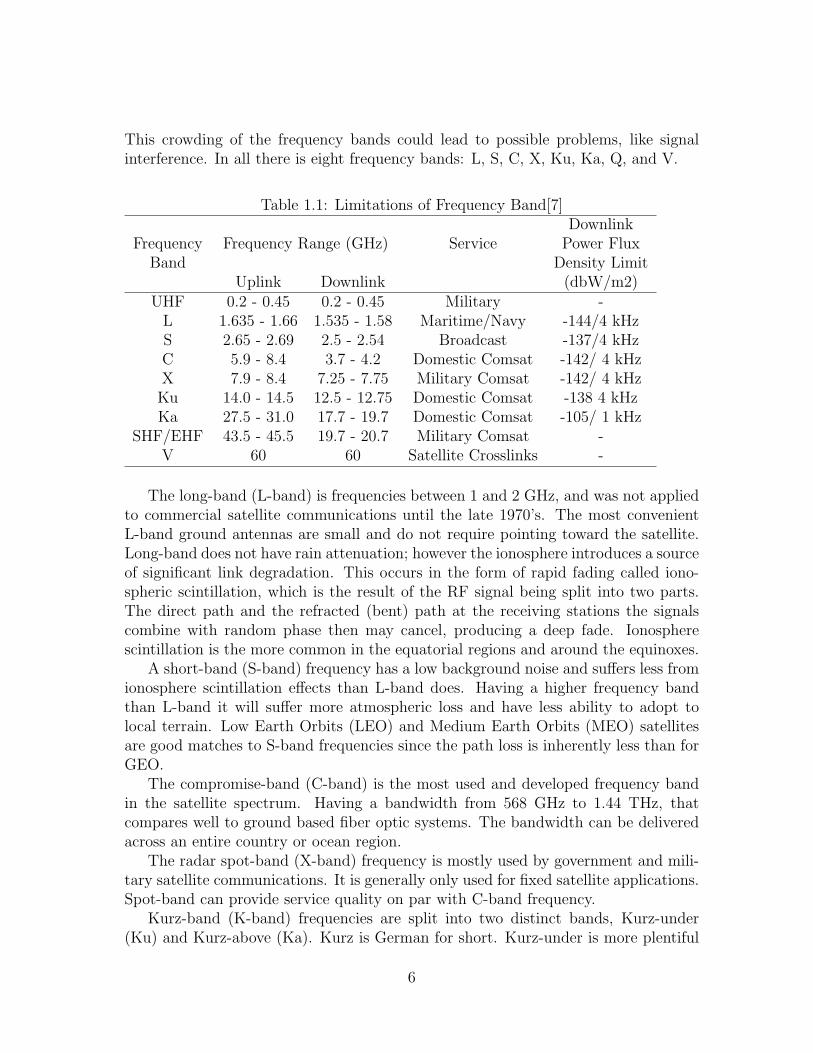
This crowding of the frequency bands could lead to possible problems, like signalinterference. In all there is eight frequency bands: L, S, C, X, Ku, Ka, Q, and V.
Table 1.1: Limitations of Frequency Band[7]Downlink
Frequency Frequency Range (GHz) Service Power FluxBand Density Limit
Uplink Downlink (dbW/m2)UHF 0.2 - 0.45 0.2 - 0.45 Military -
L 1.635 - 1.66 1.535 - 1.58 Maritime/Navy -144/4 kHzS 2.65 - 2.69 2.5 - 2.54 Broadcast -137/4 kHzC 5.9 - 8.4 3.7 - 4.2 Domestic Comsat -142/ 4 kHzX 7.9 - 8.4 7.25 - 7.75 Military Comsat -142/ 4 kHzKu 14.0 - 14.5 12.5 - 12.75 Domestic Comsat -138 4 kHzKa 27.5 - 31.0 17.7 - 19.7 Domestic Comsat -105/ 1 kHz
SHF/EHF 43.5 - 45.5 19.7 - 20.7 Military Comsat -V 60 60 Satellite Crosslinks -
The long-band (L-band) is frequencies between 1 and 2 GHz, and was not appliedto commercial satellite communications until the late 1970’s. The most convenientL-band ground antennas are small and do not require pointing toward the satellite.Long-band does not have rain attenuation; however the ionosphere introduces a sourceof significant link degradation. This occurs in the form of rapid fading called iono-spheric scintillation, which is the result of the RF signal being split into two parts.The direct path and the refracted (bent) path at the receiving stations the signalscombine with random phase then may cancel, producing a deep fade. Ionospherescintillation is the more common in the equatorial regions and around the equinoxes.
A short-band (S-band) frequency has a low background noise and suffers less fromionosphere scintillation effects than L-band does. Having a higher frequency bandthan L-band it will suffer more atmospheric loss and have less ability to adopt tolocal terrain. Low Earth Orbits (LEO) and Medium Earth Orbits (MEO) satellitesare good matches to S-band frequencies since the path loss is inherently less than forGEO.
The compromise-band (C-band) is the most used and developed frequency bandin the satellite spectrum. Having a bandwidth from 568 GHz to 1.44 THz, thatcompares well to ground based fiber optic systems. The bandwidth can be deliveredacross an entire country or ocean region.
The radar spot-band (X-band) frequency is mostly used by government and mili-tary satellite communications. It is generally only used for fixed satellite applications.Spot-band can provide service quality on par with C-band frequency.
Kurz-band (K-band) frequencies are split into two distinct bands, Kurz-under(Ku) and Kurz-above (Ka). Kurz is German for short. Kurz-under is more plentiful
6
than C-band frequency. The downside to Ku-band is that it has more rain attenuationthen C-band. It has regional shaped spot beams with geographic separation allowingup to approximately ten times the frequency reuse. Kurz-under is used for radar andcommunications satellites.
Kurz-above is abundant and therefore attractive for services that cannot findroom at lower frequencies. Ground antenna beamwidths are between one-half andone-quarter the values that correspond at Ku- and C-bands, allowing more satellitesto be accommodated. Kurz-above has many challenges corresponding with it. It hasa much greater attenuation for a given amount of rain fall. This can be overcomeby increasing the transmitted power or receiver sensitivity to gain link margin, orreducing the data rate during rain fall.
The Q- and V-bands are frequencies above 30 GHz. These bands are still con-sidered to be experimental in nature and not many organizations have seen fit toexploit this region. Intense rain attenuation and more atmospheric absorption can beexperienced on space-ground paths.
1.1.4 Link Budget
The link budget is the method of determining the received power and noise powerin a link. The link budget depends on several key factors in the calculation. Thesefactors include the type of transponder available on the satellite, the alignment ofthe antenna, the gain of the antenna, the atmospheric losses and the weather effectson the signal. The alignment of the antenna is important in the calculations becausethe power and quality of the signal decreases as the antenna moves further out ofalignment. The alignment for the antenna includes both the alignment of the antennaon the satellite and also the alignment of the antenna for the ground station. Formost calculations, the alignment of the antenna for the ground station is assumed tobe aligned perfectly at the satellite. The atmosphere also plays an important part inthe calculation of the link budget since the atmosphere is a source for noise as wellas power reduction in the signal. Atmospheric losses are calculated for clear sky orclear air. The addition of weather into the atmosphere produces more loss in termsof power received and a greater amount of signal noise temperature.
Link budgets are calculated at the worst conditions possible. The conditions,which contribute to a worst-case link budget, include having the ground station onthe edge of the satellite visibility, having a low angle of elevation of the satellite, andhaving poor weather conditions like rain. The effect of having the ground station onthe edge of the satellite visibility is that the received signal is usually 3 dB lower thenif the ground station was located at the center of the satellite coverage area. Anothereffect that is also associated with the ground station being located at the edge ofsatellite visibility is that the path length between satellite and ground station is at itsmaximum. The path length is important to take into consideration because the signalquality decreases as the path length increases. The effect of having a low elevation
7
angle of the satellite is that the signal transmission will have the highest atmosphericattenuation in clear air. The presence of rain or other poor weather conditions wouldincrease rain attenuation.
1.2 Telemetry, Computer, Command and Data Han-
dling
The computer, C&DH, and telemetry systems make up the functional nervous systemof any spacecraft bus. Without these systems, a spacecraft cannot fulfill its intendedmission. Should any one of these systems fail permanently without a redundantbackup, the spacecraft is lost. We now address some of the key concerns of the designof these systems, and discuss fundamental concepts involved in the basic structure ofthat design.
1.2.1 Computer States and State Diagrams
A state diagram provides a convenient method to begin determining computer re-quirements. The most basic states included in a state diagram are usually ON andOFF. We generally incorporate the OFF mode into system states even if we designthe system operate continuously in the event of an unexpected shutdown. Other com-puter states exist depending on specific mission requirements. A state diagram showsall the states in a system and the requirements to achieve different states. Figure 1.1shows a typical state diagram for an onboard computer system.
1.2.2 Interface Design and Architecture Selection
Once the basic states for a system are defined, an architecture to govern the in-teraction between the processor and subsystems must be created. In developing anarchitecture for any system, several factors must be considered: the data architec-ture, the hardware architecture, and the software architecture. Some examples ofcommon architectures for computer systems are centralized, ring, federated bus, anddistributed bus architectures.
In a centralized architecture, all of the other systems, such as sensors and thrustersare directly connected to the central processor. This is convenient because it allowseverything to interface directly with the central processor. It also stops failures withone subsystem from affecting other subsystems. However, because all the systems areconnected directly to the central processor, this architecture requires more space andcomplicates the addition of other subsystems into the design.
In a ring architecture, all of the subsystems connected to the central processorare connected in series, allowing data from one subsystem to pass to the processorby way of the other subsystems. Although this architecture is less reliable due to the
8
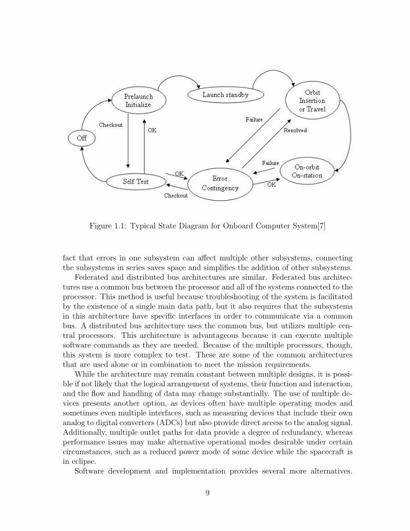
Figure 1.1: Typical State Diagram for Onboard Computer System[7]
fact that errors in one subsystem can affect multiple other subsystems, connectingthe subsystems in series saves space and simplifies the addition of other subsystems.
Federated and distributed bus architectures are similar. Federated bus architec-tures use a common bus between the processor and all of the systems connected to theprocessor. This method is useful because troubleshooting of the system is facilitatedby the existence of a single main data path, but it also requires that the subsystemsin this architecture have specific interfaces in order to communicate via a commonbus. A distributed bus architecture uses the common bus, but utilizes multiple cen-tral processors. This architecture is advantageous because it can execute multiplesoftware commands as they are needed. Because of the multiple processors, though,this system is more complex to test. These are some of the common architecturesthat are used alone or in combination to meet the mission requirements.
While the architecture may remain constant between multiple designs, it is possi-ble if not likely that the logical arrangement of systems, their function and interaction,and the flow and handling of data may change substantially. The use of multiple de-vices presents another option, as devices often have multiple operating modes andsometimes even multiple interfaces, such as measuring devices that include their ownanalog to digital converters (ADCs) but also provide direct access to the analog signal.Additionally, multiple outlet paths for data provide a degree of redundancy, whereasperformance issues may make alternative operational modes desirable under certaincircumstances, such as a reduced power mode of some device while the spacecraft isin eclipse.
Software development and implementation provides several more alternatives.
9
While software cannot provide performance beyond the physical limits of the onboardinstrumentation, it can affect how efficiently that instrumentation operates. Becausethe addition of new software functionality carries a very small cost in terms of mass,fuel, and similar cost factors compared to the addition of hardware functionality, abroad range of additional software functionality can be made available.
1.2.3 Software
Onboard software may be classified in one of two categories: individual elements ofsoftware to run different processes; and the complete operating system (OS). Theoperating system itself does not directly provide any spacecraft function or directlyservice any onboard system. Rather, it facilitates the operation of the computersystem in much the same way that the spacecraft bus facilitates the operation ofthe spacecraft. It provides the housekeeping and background administration withoutwhich the computer could provide no useful function, and controls the executionof the individual software programs that do provide service for and administer theoperation of the spacecraft systems.
The OS is generally based on what is known as a kernel, which is essentially anindividual program. As far as the processor and hardware know, the computer isrunning this kernel. But that program divides time into small intervals, and thusaffects the multitasking necessary to allow multiple programs to share the systemprocessor.
The kernel is typically a custom written, proprietary piece of code written specif-ically for the spacecraft, although it is not unheard of to use some type of Unix orWindows kernel. Typically when using a commercial kernel, the kernel itself has manymodifications made to it before it is installed into the spacecraft. These kernel can beas small as required by the mission specifications, although after a certain point theycan lose functionality. Determining the size of the OS and system run overtop of itis important in determining the type of computer used in the spacecraft. Dependingon the mission requirements, the computer may run nothing more than a modified,commercial, off-the-shelf (COTS) OS or a more specialized one.
Required application-specific software varies with varying mission requirementsand onboard hardware, including payload hardware. Two classes of approaches tosystem architecture prevail. With a lower performance computer system, data col-lected from bus and payload subsystems may be passed unprocessed and uncom-pressed directly to the ground station. With a higher performance system, data maybe processed and/or compressed before anything is relayed to the ground. Thus,the interaction between the selection of computing power and communication systembandwidth is clear and substantial.
The partitioning of computational services necessary to the overall space systeminto ground and space portions becomes a consideration in computer system designwhen this division of computation effort is considered. This is a relatively new consid-
10
eration made possible by the swift increase in computer power in recent years, coupledwith a decrease in required electrical power. Traditionally, few options existed. Be-cause of mass and power limitations, and because computers were massive and powerhungry, the only choice was to keep the onboard systems as simple as possible, and todo as little processing as absolutely necessary onboard. This resulted in a large datastream being fed down to the ground station. But with modern computing power, itis not only possible, but highly desirable to do as much processing and compressiononboard as possible, so as to conserve downlink bandwidth, and only provide rawdata when the mission specifically requires it.
This division of computational function is extended into the spacecraft subsystemsas well. The onboard data bus is another bandwidth-limited choke point, not unlikethe downlink between spacecraft and ground station. Thus, the same issues arisein determining whether the computer, or the individual hardware devices should domore or less of the processing of raw data.
1.2.4 Flow Diagrams
One of the better ways to describe subsystem functions is with a functional flowdiagram. This diagram breaks up a system function into smaller subsections in theorder that they are performed. Once the basic subsections are identified, it can alsobe broken down further into more subsections for analysis. Functional flow diagramscan also be used to describe data-flow.
Data-flow diagrams are used primarily to make sure that collected data from amission is utilized efficiently. They allow the designer to plan out what they intend todo before they begin looking into details about how to go about doing it. A completedata-flow diagram is considered the starting point for designing the hardware forthe system. These diagrams also help make up the requirements for networking thesystem.
1.2.5 Operating Budget Considerations
Since computers are constantly becoming smaller and more power-efficient in recentyears, one may be tempted to presume that the mass and electrical draw of a com-puter would be insignificant on any spacecraft. While it must be admitted that thispresumption would hold true for a great many spacecraft, it most certainly cannotbe accepted as universal.
There are nanosatellites with a total mass of just a few pounds. Since even thesmallest moderately-powered computers with power comparable to modern desktoppersonal computers (PCs) weigh two to three pounds, the mass of the computer canbe significant. Similarly, while the power draw of a computer may be as little as 5 -10 W, that may account for the majority of the power budget on some lower powerspacecraft.
11
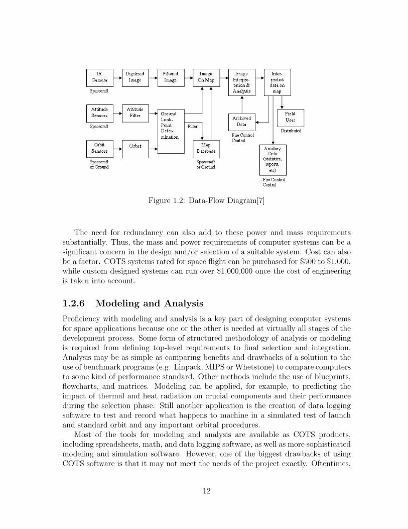
Figure 1.2: Data-Flow Diagram[7]
The need for redundancy can also add to these power and mass requirementssubstantially. Thus, the mass and power requirements of computer systems can be asignificant concern in the design and/or selection of a suitable system. Cost can alsobe a factor. COTS systems rated for space flight can be purchased for $500 to $1,000,while custom designed systems can run over $1,000,000 once the cost of engineeringis taken into account.
1.2.6 Modeling and Analysis
Proficiency with modeling and analysis is a key part of designing computer systemsfor space applications because one or the other is needed at virtually all stages of thedevelopment process. Some form of structured methodology of analysis or modelingis required from defining top-level requirements to final selection and integration.Analysis may be as simple as comparing benefits and drawbacks of a solution to theuse of benchmark programs (e.g. Linpack, MIPS or Whetstone) to compare computersto some kind of performance standard. Other methods include the use of blueprints,flowcharts, and matrices. Modeling can be applied, for example, to predicting theimpact of thermal and heat radiation on crucial components and their performanceduring the selection phase. Still another application is the creation of data loggingsoftware to test and record what happens to machine in a simulated test of launchand standard orbit and any important orbital procedures.
Most of the tools for modeling and analysis are available as COTS products,including spreadsheets, math, and data logging software, as well as more sophisticatedmodeling and simulation software. However, one of the biggest drawbacks of usingCOTS software is that it may not meet the needs of the project exactly. Oftentimes,
12
large organizations with sufficient resources use custom modeling software. The bestoption for smaller companies, however, is to use COTS software and tailor it asnecessary.
As previously stated, knowing how to use the right modeling and analysis tools isof great importance to integration and testing. Testing at every stage of development,building up incrementally from the lowest (unit) level to the highest (system) level,ensures that the final product (or space system) will meet the mission objectives.It also serves to reduce the complexity and the risk involved. Because this kind ofrigorous testing directs the subsystems toward a configuration that meets top-level,system requirements, there will at least be an increase of confidence (or assurance)in the overall performance of the integrated whole system.
Maintaining communication with members of other functional groups during theC&DH system design is essential to the success of the mission. Because the C&DHsystem handles all data for the spacecraft, and because payload data needs can vary sogreatly, most aspects of computer design are affected by other functional groups. Forthis reason, the C&DH system is often one of the last to be designed and/or selectedfor a given spacecraft, once all operating parameters of the other systems have beenestablished. For example, various computers will control or monitor the differentsubsystems on board the spacecraft. These may include directing the Sun and Earthsensors, controlling gyros and thrusters, error determination, power management, andthermal control, all of which operate under specific parameters that are decided by theother functional groups to accomplish the overall mission. These parameters mustbe taken into consideration when designing computer and data handling softwareor hardware, as well as how successfully the total system interfaces. Appropriatesoftware capable of handing the data from the sensors, compensating for trackingerror and determining the spacecraft attitude would be needed. The right type ofhardware would be needed to communicate this information to whatever subsystemis responsible for the onboard thrusters or other attitude control systems to make anynecessary attitude correction.
Computer Operation
Developing a working model of computer operation is a valuable tool in the selectionand/or design of a flight computer system. This can be done with custom softwarethat calculates processing time, power requirements, and other resource usage, or evenruns simulated computations in an elaborate simulation environment. It may also bedone largely by rough estimation using simpler analysis tools such as spreadsheetsand basic algorithm analysis of the software routines to be employed.
Using the more elaborate methods also allows for all the additional benefits ofsimulation, in that software can be written and tested in the simulation, results canbe compared to those expected, and performance may be evaluated before the systemis ever built.
13
1.3 Conclusion
Inside of the CC&DH functional division, there are two major subsystems. The com-munications subsystem describes how the spacecraft interacts with ground stationsand other spacecraft. It covers in detail how the spacecraft will receive data, at whatspeed it will receive it, and how it will send data back to the source in a useful form.The C&DH subsystem covers how data and commands are handled internally by thespacecraft. In the next section these subsystems are looked at in greater detail, de-scribing how they are modeled as well as giving an in depth look at the interactionsbetween various subsystems.
14
Chapter 2
Modeling and Analysis
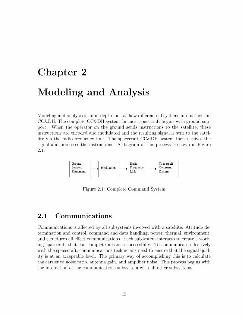
Modeling and analysis is an in-depth look at how different subsystems interact withinCC&DH. The complete CC&DH system for most spacecraft begins with ground sup-port. When the operator on the ground sends instructions to the satellite, theseinstructions are encoded and modulated and the resulting signal is sent to the satel-lite via the radio frequency link. The spacecraft CC&DH system then receives thesignal and processes the instructions. A diagram of this process is shown in Figure2.1.
Figure 2.1: Complete Command System
2.1 Communications
Communications is affected by all subsystems involved with a satellite. Attitude de-termination and control, command and data handling, power, thermal, environment,and structures all effect communications. Each subsystem interacts to create a work-ing spacecraft that can complete missions successfully. To communicate effectivelywith the spacecraft, communications technicians need to ensure that the signal qual-ity is at an acceptable level. The primary way of accomplishing this is to calculatethe carrier to noise ratio, antenna gain, and amplifier noise. This process begins withthe interaction of the communications subsystem with all other subsystems.
15
2.1.1 Effect of Other Subsystems on Communications
The communications systems on satellites are affected by several other satellite sub-systems. The other subsystems that affect the communications subsystem includethe attitude determination and control system (ADCS), the command and data han-dling system (C&DH), the power, thermal, and environment system (PT&E), andthe structures and launch vehicle system (S&LV). All of these systems affect thecommunications subsystem.
The ADCS affects the communications subsystem by ensuring that the antennais aligned in the desired direction, particularly in GEO. Since the earth station an-tennas used are normally fixed, movement of the satellite away from its appointedposition in the sky will cause a loss of signal. When a satellite link is established,the ideal situation is to have the earth station and the satellite antennas aligned formaximum gain. This need for continuous communications is a problem for the ADCStechnicians.
The C&DH system relies on the communications subsystem in order to receiveand send data from the ground station. The C&DH system determines the amountof data that is required to be sent through the link with the ground station. Thecommand system is used to make changes in attitude and corrections to the orbit.The communications system is controlled by the command system.
The PT&E systems are relied upon to provide electrical power and insulation. Dueto continuous computing, over heating is a factor for computer and communicationscomponents. The overheating of components produces an increase of noise, and areduction in the SNR. Communications systems require adequate power to performwithin the given mission parameters.
The S&LV subsystem is important in the design of communications subsystem.The type of antenna array that can be deployed is dependant on the launch vehicleselected. The placement of antennas and transponders are important in the effec-tiveness of the communications systems. The distance between the antennas andtransponders is proportional to the amount of feeder loss in the system. In order toattain the best SNR, the feeder loss in the system should be minimized.
2.1.2 Communication System Modeling
The communications subsystem can be modeled by several equations. These equa-tions deal with the calculation of the carrier-to-noise ratio (C/N), the amplifier noise,the feeder loss, the rain effects, and the antenna gain.
Carrier to Noise Ratio
The main measure of effectiveness of a communications link is the carrier to noiseratio. The C/N depends on several important factors. The C/N can be modeled bythe equation:
16
C
N=PR
PN
(2.1)
where PR is the received power and PN is the noise power. The C/N can also bemodeled in terms of decibels by the equation:
[C
N
]= [PR]− [PN ] (2.2)
where [C/N ] is the decibel equivalent of C/N, [PR] is the received power and [PN ] isthe noise power both in terms of decibels. In order to convert between a ratio andthe decibel equivalent, a log10 conversion is needed. The log10 conversion is modeledby the equation:
[x(dB)] = 10 log10(x) (2.3)
where x is the variable being used in the conversion. Several factors are involvedin the determination of the received power and the noise power.
The received power can be modeled by the following equation:
[PR] = [EIRP ] + [GR]− ([FSL] + [RFL] + [AML] + [AA] + [PL]) (2.4)
where EIRP is the equivalent isotropic radiated power, GR is receiver antenna gain,FSL is free-space spreading loss, RFL is receiver feeder loss, AML is antenna mis-alignment loss, AA is the atmospheric absorption, and PL is polarization mismatchloss. Free-space spreading loss, receiver feeder loss, antenna misalignment loss, atmo-spheric absorption, and polarization mismatch can all be grouped into one variable,Losses. The Losses can be written as:
[Losses] = [FSL] + [RFL] + [AML] + [AA] + [PL] (2.5)
17
The free space spreading loss can be determined in decibels by the equation:
[FSL] = 20 log10(4πDsg
λ) (2.6)
where Dsg is the distance from the satellite to the ground station. These equationscan be combined into the simplified power received equation:
[PR] = [EIRP ] + [GR]− [Losses] (2.7)
The power received by the satellite is one of the main components in the carrierto noise ratio.
The noise power from a thermal noise source can be modeled by:
PN = kTNBN (2.8)
where PN is the available noise power, k is Boltzmann’s constant, TN is the equivalentnoise temperature, and BN is the equivalent noise bandwidth. The noise power canalso be expressed in terms of decibels by the equation:
[PN ] = [k] + [TN ] + [BN ] (2.9)
The noise power from thermal noise directly relates to the noise per unit bandwidth,termed the noise power spectral density, equated by:
N0 =PN
BN
(2.10)
The saturation flux density is needed to calculate the uplink carrier to noise ra-tio. It is also needed to calculate the EIRP at the earth station. The saturation fluxdensity is modeled by:
18
ψM =EIRP
4πr2(2.11)
where r is the radius of the antenna. The EIRP , which the earth station mustprovide, is modeled by:
[EIRP ] = [ψM ] + [A0] + [Losses]− [RFL] (2.12)
where A0 is the effective area for an isotropic antenna. The EIRP is the mini-mum value the earth station must provide, in clear sky conditions.
The uplink carrier to noise ratio is modeled by:
[C
N
]U
= [ψS] + [A0]− [BO]i +[G
T
]U− [k]− [RFL] (2.13)
where BO is the specified backoff. The downlink carrier to noise ratio is modeledby:
[C
N
]D
= [EIRP ]D +[G
T
]D− [Losses]D − [k]− [B] (2.14)
where B is the bandwidth signal. Both the uplink and downlink equations are forclear sky conditions.
Amplifier Noise
The amplifier noise can be split up into two different sources the input and outputnoise. The output noise can be modeled by:
N0,out = Gk(Tant + Te) (2.15)
19
where N0,out is the output noise, G is the available power gain of the amplifier, Tant
is the antenna temperature, and Te is the equivalent input noise temperature for theamplifier. The input noise is modeled by:
N0,in = k(Tant + Te) (2.16)
with N0,in is the input noise.
The alternative way of representing amplifier noise is by means of its noise factor. Indefining the noise factor of an amplifier, it is taken to be at room temperature. Theoutput noise is modeled by:
N0,out = GKFT0 (2.17)
where F is the noise factor, and To is room temperature. Room temperature isgenerally taken to be 290 K.
Feeder Loss
Feeder loss is the loss that occurs in the connection between the antenna and receiver.Similar losses occur between the transmitter and antenna as well. The power outputfrom the amplifier due to feeder loss is modeled by:
PTX = PTLFTX (2.18)
where PT is the antenna power, PTX is the power output, and LFTX is the feederloss. The signal power input to the receiver from the antenna can be modeled by:
PRX =PR
LFRX
(2.19)
20
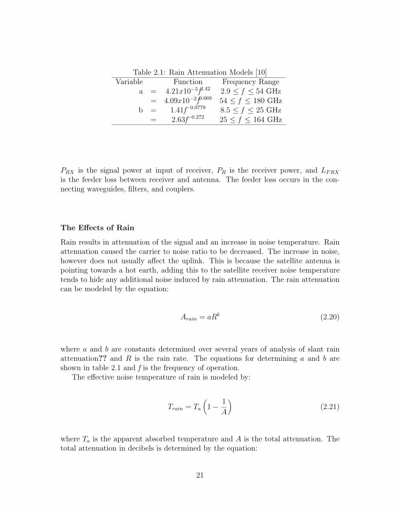
Table 2.1: Rain Attenuation Models [10]Variable Function Frequency Range
a = 4.21x10⁻⁵f2.42 2.9 ≤ f ≤ 54 GHz= 4.09x10⁻²f0.669 54 ≤ f ≤ 180 GHz
b = 1.41f−0.0779 8.5 ≤ f ≤ 25 GHz= 2.63f−0.272 25 ≤ f ≤ 164 GHz
PRX is the signal power at input of receiver, PR is the receiver power, and LFRX
is the feeder loss between receiver and antenna. The feeder loss occurs in the con-necting waveguides, filters, and couplers.
The Effects of Rain
Rain results in attenuation of the signal and an increase in noise temperature. Rainattenuation caused the carrier to noise ratio to be decreased. The increase in noise,however does not usually affect the uplink. This is because the satellite antenna ispointing towards a hot earth, adding this to the satellite receiver noise temperaturetends to hide any additional noise induced by rain attenuation. The rain attenuationcan be modeled by the equation:
Arain = aRb (2.20)
where a and b are constants determined over several years of analysis of slant rainattenuation?? and R is the rain rate. The equations for determining a and b areshown in table 2.1 and f is the frequency of operation.
The effective noise temperature of rain is modeled by:
Train = Ta
(1− 1
A
)(2.21)
where Ta is the apparent absorbed temperature and A is the total attenuation. Thetotal attenuation in decibels is determined by the equation:
21
A = Acs + Arain (2.22)
where Acs is the atmospheric attenuation and Arain is the additional attenuationdue to rain. The rain noise temperature is needed to calculate the total sky-noisetemperature. The total sky noise is modeled by:
Tsky = TCS + Train (2.23)
where TCS is the clear sky temperature and Tsky is the total sky noise tempera-ture.
In order to determine the resulting C/N from rain attenuation, the inverse of theC/N has to be found. The equation to determine the inverse is:
[N0
C
]= 10(−1
10 )[C
N0
](2.24)
The inverse of the C/N had to be determined because the inverses have additiveproperties. The method for taking the resulting overall inverse of the C/N is:
[C
N0
]= −10 log
(N0
C
)(2.25)
The overall C/N is the measure of effectiveness of the communications system.
The inverse of the C/N for rain is determined by the equation:
(N
C
)rain
=(N
C
)CS
(A+ (A− 1)
Ta
TS,CS
)(2.26)
where TS,CS is the clear sky temperature.
22
Antenna Gain
An important factor in determining the C/N is the antenna gain. The antenna gainis based on the geometry of the antenna and the operating wavelength of the signal.The equation for the antenna gain is:
GR =ηA4πAant
λ2(2.27)
where Aant is the area of the antenna aperture, λ is the operating wave length, andηA is the aperture efficiency. The area of the antenna aperture can be modeled by hearea of a circle and follows the equation:
Aant = 4πr2 (2.28)
Another needed equation is the relationship between frequency and wavelength. Thefrequency and the wavelength are related through the equation:
fλ = c (2.29)
where f is the operating frequency and c is the speed of light. These equationsare needed in the modeling of the communications system.
2.1.3 Sizing of Communications System
The reason that the communications system was modeled by equations was to de-termine the size needed for the communications system. The sizing of the commu-nications system is important in the design of every spacecraft. A communicationssystem needs to be designed so that the requirements of the mission are met whilenot imposing too great of a cost on the mission. The costs that can be imposedon the mission by the communications system are the additional mass and powerrequirements.
23
The sizing of the antenna system is dependent on the desired gain and the desiredC/N ratio. The link budget is used to determine the sizing of the communicationssystems. The link budget output is compared with the threshold C/N ratio. Thethreshold C/N ratio is the C/N that yields a still favorable signal. The main vari-ables that the link budget deals with is the size of the antennas, the power of thetransponder and the frequency of operation. The ground station antenna is mainlyfixed but the designer can alter the diameter of the antenna on the spacecraft. If thelink budget C/N ratio is greater then the threshold C/N, the antenna diameter onthe spacecraft can be decreased until the desired C/N ratio is found.
2.1.4 Interactions of Subsystems
The communications subsystem mainly interacts with one other subsystem. Thesubsystem that the communications subsystem interacts with is the command anddata handling subsystem. The communications subsystem provides the link betweenthe ground station and the satellite. The data is received from the ground stationthrough the antenna. The data is then sent through the receiver. The receiver filtersand amplifies the received signal. The signal is then passed through a modulator. Themodulator alters the signal in order for the computer system to utilize the incomingdata. The modulator is the main connection between the communications subsystemand the computer subsystem.
The data that is needed to be sent to the ground station is passed through asimilar system. The data is modulated to attain the proper frequency. The signal isthen amplified in order to attain the desired SNR and is sent to the ground stationby means of the antenna.
The main objective of communications is sending and receiving signals to and fromearth ground stations. In this process computer and data handling are used to alterthe input signal so it is ready to be outputted. To even start this process the signalto noise ratio needs to be calculated to ensure the signal will be received. There aremany factors that come into play when calculating the signal to noise ration. Clearsky conditions tend to alter the signal less allowing for a better quality signal, whilerainfall causes attenuation potentially altering the signal and jeopardizing its quality.After this step the spacecraft command system will take the recognizable signal andstart a process to ensure the information is outputted correctly.
2.2 Spacecraft Command System
Once the communications process has finished and the spacecraft has received arecognizable signal, it has another process to begin. The signal is first sent to areceiver for demodulation and amplification, resulting in a command. This commandis decoded and its validity is determined. If the command system decides that thecommand comes from a valid source, the now-decoded command is passed through
24
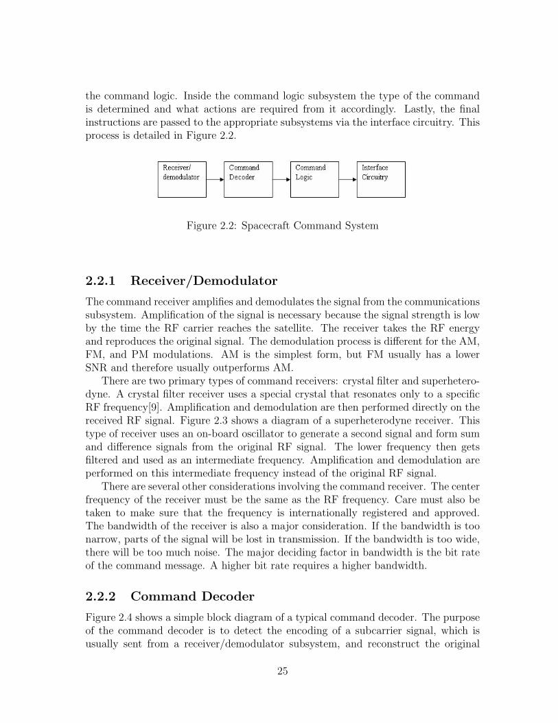
the command logic. Inside the command logic subsystem the type of the commandis determined and what actions are required from it accordingly. Lastly, the finalinstructions are passed to the appropriate subsystems via the interface circuitry. Thisprocess is detailed in Figure 2.2.
Figure 2.2: Spacecraft Command System
2.2.1 Receiver/Demodulator
The command receiver amplifies and demodulates the signal from the communicationssubsystem. Amplification of the signal is necessary because the signal strength is lowby the time the RF carrier reaches the satellite. The receiver takes the RF energyand reproduces the original signal. The demodulation process is different for the AM,FM, and PM modulations. AM is the simplest form, but FM usually has a lowerSNR and therefore usually outperforms AM.
There are two primary types of command receivers: crystal filter and superhetero-dyne. A crystal filter receiver uses a special crystal that resonates only to a specificRF frequency[9]. Amplification and demodulation are then performed directly on thereceived RF signal. Figure 2.3 shows a diagram of a superheterodyne receiver. Thistype of receiver uses an on-board oscillator to generate a second signal and form sumand difference signals from the original RF signal. The lower frequency then getsfiltered and used as an intermediate frequency. Amplification and demodulation areperformed on this intermediate frequency instead of the original RF signal.
There are several other considerations involving the command receiver. The centerfrequency of the receiver must be the same as the RF frequency. Care must also betaken to make sure that the frequency is internationally registered and approved.The bandwidth of the receiver is also a major consideration. If the bandwidth is toonarrow, parts of the signal will be lost in transmission. If the bandwidth is too wide,there will be too much noise. The major deciding factor in bandwidth is the bit rateof the command message. A higher bit rate requires a higher bandwidth.
2.2.2 Command Decoder
Figure 2.4 shows a simple block diagram of a typical command decoder. The purposeof the command decoder is to detect the encoding of a subcarrier signal, which isusually sent from a receiver/demodulator subsystem, and reconstruct the original
25
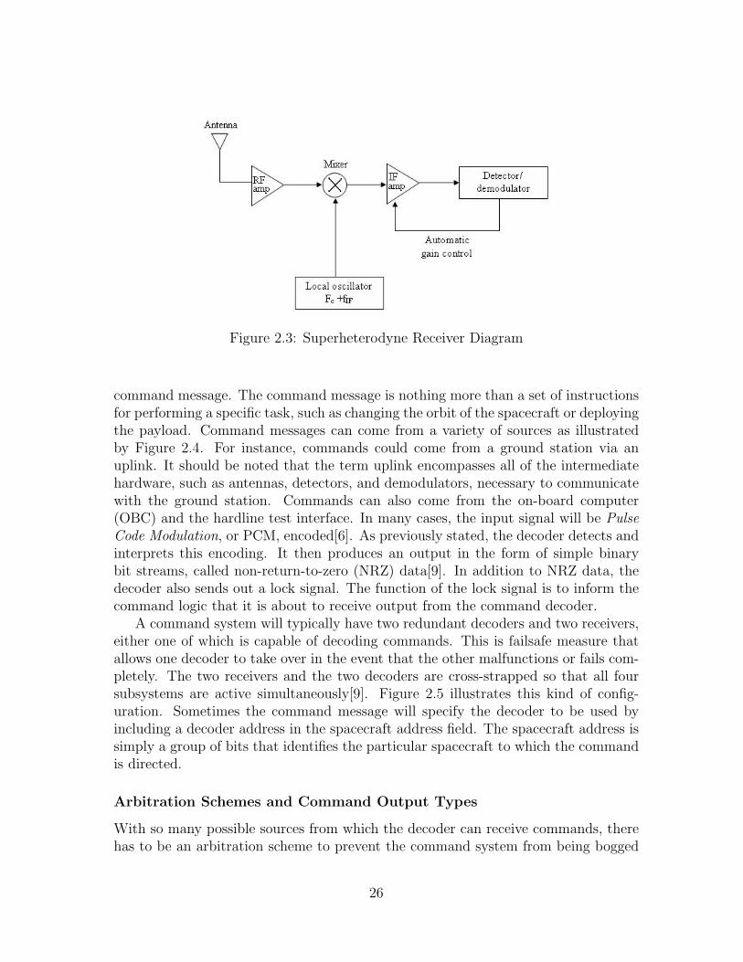
Figure 2.3: Superheterodyne Receiver Diagram
command message. The command message is nothing more than a set of instructionsfor performing a specific task, such as changing the orbit of the spacecraft or deployingthe payload. Command messages can come from a variety of sources as illustratedby Figure 2.4. For instance, commands could come from a ground station via anuplink. It should be noted that the term uplink encompasses all of the intermediatehardware, such as antennas, detectors, and demodulators, necessary to communicatewith the ground station. Commands can also come from the on-board computer(OBC) and the hardline test interface. In many cases, the input signal will be PulseCode Modulation, or PCM, encoded[6]. As previously stated, the decoder detects andinterprets this encoding. It then produces an output in the form of simple binarybit streams, called non-return-to-zero (NRZ) data[9]. In addition to NRZ data, thedecoder also sends out a lock signal. The function of the lock signal is to inform thecommand logic that it is about to receive output from the command decoder.
A command system will typically have two redundant decoders and two receivers,either one of which is capable of decoding commands. This is failsafe measure thatallows one decoder to take over in the event that the other malfunctions or fails com-pletely. The two receivers and the two decoders are cross-strapped so that all foursubsystems are active simultaneously[9]. Figure 2.5 illustrates this kind of config-uration. Sometimes the command message will specify the decoder to be used byincluding a decoder address in the spacecraft address field. The spacecraft address issimply a group of bits that identifies the particular spacecraft to which the commandis directed.
Arbitration Schemes and Command Output Types
With so many possible sources from which the decoder can receive commands, therehas to be an arbitration scheme to prevent the command system from being bogged
26
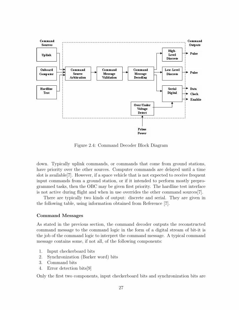
Figure 2.4: Command Decoder Block Diagram
down. Typically uplink commands, or commands that come from ground stations,have priority over the other sources. Computer commands are delayed until a timeslot is available[7]. However, if a space vehicle that is not expected to receive frequentinput commands from a ground station, or if it intended to perform mostly prepro-grammed tasks, then the OBC may be given first priority. The hardline test interfaceis not active during flight and when in use overrides the other command sources[7].
There are typically two kinds of output: discrete and serial. They are given inthe following table, using information obtained from Reference [7].
Command Messages
As stated in the previous section, the command decoder outputs the reconstructedcommand message to the command logic in the form of a digital stream of bit-it isthe job of the command logic to interpret the command message. A typical commandmessage contains some, if not all, of the following components:
1. Input checkerboard bits2. Synchronization (Barker word) bits3. Command bits4. Error detection bits[9]
Only the first two components, input checkerboard bits and synchronization bits are
27
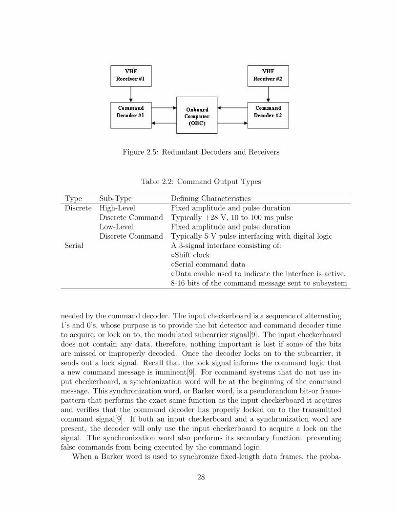
Figure 2.5: Redundant Decoders and Receivers
Table 2.2: Command Output Types
Type Sub-Type Defining CharacteristicsDiscrete High-Level Fixed amplitude and pulse duration
Discrete Command Typically +28 V, 10 to 100 ms pulseLow-Level Fixed amplitude and pulse durationDiscrete Command Typically 5 V pulse interfacing with digital logic
Serial A 3-signal interface consisting of:◦Shift clock◦Serial command data◦Data enable used to indicate the interface is active.8-16 bits of the command message sent to subsystem
needed by the command decoder. The input checkerboard is a sequence of alternating1’s and 0’s, whose purpose is to provide the bit detector and command decoder timeto acquire, or lock on to, the modulated subcarrier signal[9]. The input checkerboarddoes not contain any data, therefore, nothing important is lost if some of the bitsare missed or improperly decoded. Once the decoder locks on to the subcarrier, itsends out a lock signal. Recall that the lock signal informs the command logic thata new command message is imminent[9]. For command systems that do not use in-put checkerboard, a synchronization word will be at the beginning of the commandmessage. This synchronization word, or Barker word, is a pseudorandom bit-or frame-pattern that performs the exact same function as the input checkerboard-it acquiresand verifies that the command decoder has properly locked on to the transmittedcommand signal[9]. If both an input checkerboard and a synchronization word arepresent, the decoder will only use the input checkerboard to acquire a lock on thesignal. The synchronization word also performs its secondary function: preventingfalse commands from being executed by the command logic.
When a Barker word is used to synchronize fixed-length data frames, the proba-
28
bility of false synchronization Pfs can be given an upper bound[9]:
Pfs < 1− (1− 2−n)m−1 (2.30)
where Pfs is the probability of false synchronization, n is the length of the Barkerword in bits, and m is the size of the data frame in bits. The table below gives sometypical values of Pfs for a fixed 32-bit synchronization word. As an example, 32-bitBarker word will be assumed to look like the following:
1111 1110 0110 1011 1000 0100 0010 0000
Table 2.2 clearly shows that as the frame size increases, the probability of falsesynchronization decreases.
Table 2.3: Typical Pfs values for a 32-bit Barker wordFrame Size (m) Pfs
1,024 3x10⁻⁷
2,048 5x10⁻⁷
4,096 9x10⁻⁷
8,192 2x10⁻⁶
16,384 3x10⁻⁶
32,768 5x10⁻⁶
65,536 1x10⁻⁵
2.2.3 Command Logic and Handling
The Earth-to-space command link provides all ground control for the satellite andrequires the highest security and reliability. Clearly, the execution of incorrect orunauthorized commands can be catastrophic. To guard against this, command han-dling system passes all commands received over the link through a robust validationprocess to ensure their authenticity and error-free reception.
Command Receipt and Verification
The implementation of secure and robust command logic is vital to the operation ofany satellite. The command logic interprets the decoded command word, verifies itsauthenticity and correctness, and executes verified commands. The system safeguardsthe satellite from unauthorized commands and unintended operation of a control dueto errors in received commands. Once the system receives and verifies commands,it may execute them immediately, or in the case of delayed commands, queue themalong with a timestamp for later execution.
29
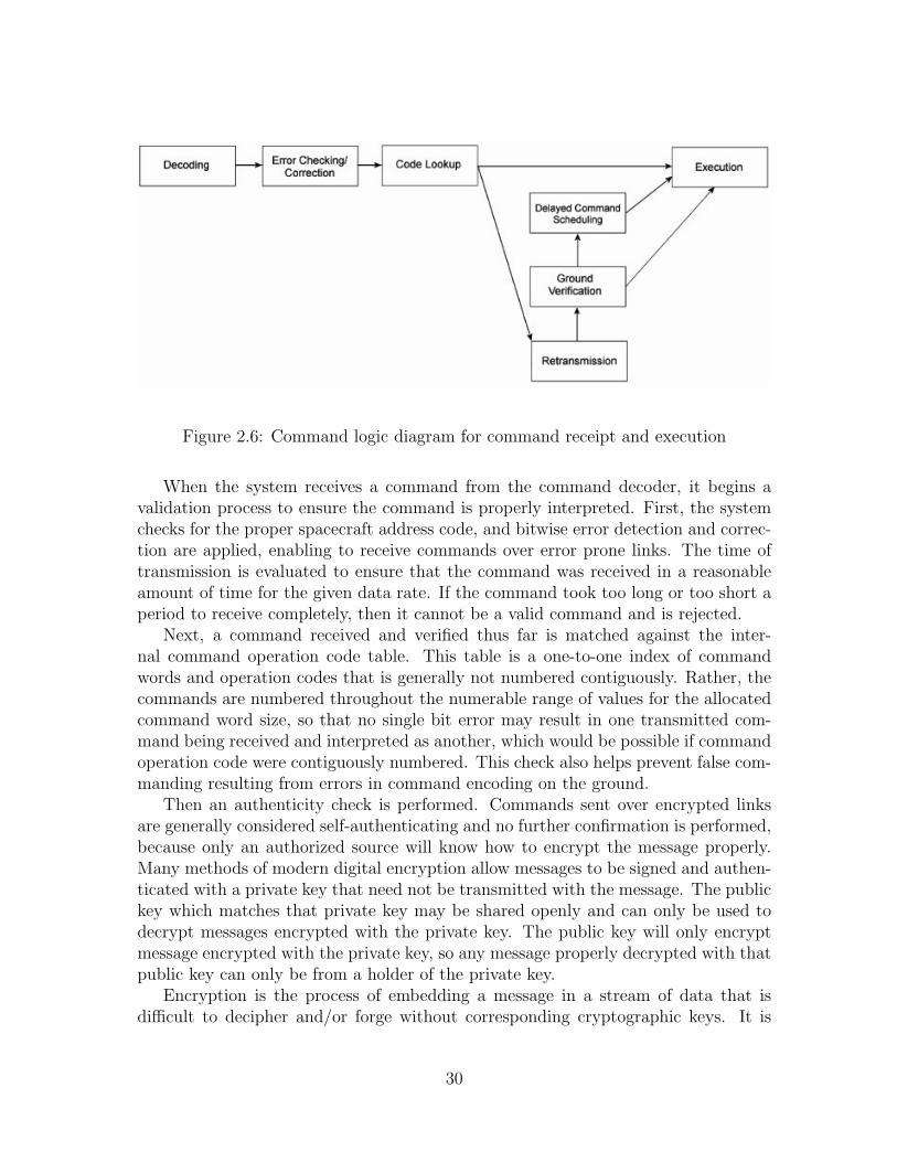
Figure 2.6: Command logic diagram for command receipt and execution
When the system receives a command from the command decoder, it begins avalidation process to ensure the command is properly interpreted. First, the systemchecks for the proper spacecraft address code, and bitwise error detection and correc-tion are applied, enabling to receive commands over error prone links. The time oftransmission is evaluated to ensure that the command was received in a reasonableamount of time for the given data rate. If the command took too long or too short aperiod to receive completely, then it cannot be a valid command and is rejected.
Next, a command received and verified thus far is matched against the inter-nal command operation code table. This table is a one-to-one index of commandwords and operation codes that is generally not numbered contiguously. Rather, thecommands are numbered throughout the numerable range of values for the allocatedcommand word size, so that no single bit error may result in one transmitted com-mand being received and interpreted as another, which would be possible if commandoperation code were contiguously numbered. This check also helps prevent false com-manding resulting from errors in command encoding on the ground.
Then an authenticity check is performed. Commands sent over encrypted linksare generally considered self-authenticating and no further confirmation is performed,because only an authorized source will know how to encrypt the message properly.Many methods of modern digital encryption allow messages to be signed and authen-ticated with a private key that need not be transmitted with the message. The publickey which matches that private key may be shared openly and can only be used todecrypt messages encrypted with the private key. The public key will only encryptmessage encrypted with the private key, so any message properly decrypted with thatpublic key can only be from a holder of the private key.
Encryption is the process of embedding a message in a stream of data that isdifficult to decipher and/or forge without corresponding cryptographic keys. It is
30
used both to protect sensitive data transmitted from the satellite from eavesdroppingand to protect the satellite command system from unauthorized commands. This isdistinct from encoding, which is merely the conversion of a message into a formatsuitable for transmission over a particular medium, in this case a low bandwidth(2,000 - 8,000 bps) high frequency digital link. Any message must be encoded fortransmission, but if it is not encrypted it may be easily forged.
For this reason, commands sent over unencrypted links are verified by retransmis-sion to the ground station over the telemetry link. If the ground station verifies thatthe correct command was received by the satellite, an execute command is sent. Be-cause of the limited communication data rate available to the command and telemetrylinks, this process may take several seconds, but is necessary to ensure only authorizedcommands are executed.
This process ensures that the probability of accepting and executing a false com-mand is minimized, generally around 1 in 10−18 to 1 in 10−22. Critical commandsmay require even lower probabilities which are generally achieved by using longeroperation codes, or splitting the command across multiple operation codes.
Command Handling and Execution
Nearly all modern command systems are microprocessor based. The processor receivescommands from the decoder, interprets them according to some internal program, andoutputs the results to the interface circuitry. The inputs are the decoded commandswhich may or may not be partially validated. The processor may then complete thevalidation, and will interpret and control execution of the command.
The most critical property of any microprocessor based command system is re-liability. The system must be fault tolerant and highly resistant to the hazards ofthe space environment. Errors in the command system can jeopardize the mission,and complete failure of the entire system will almost always result in loss of thespacecraft. This applies to both the hardware and software comprising the commandsystem. While complex software can never be guaranteed to be error-free, its designmust provide a high degree of redundancy so that errors in the command handlingprogram do not result in unintended command execution.
Local Commands
Whereas the ground station is the primary source of command data for the spacecraft,the onboard systems may generate their own commands. A finite amount of time is re-quired for the ground station to observe a condition and command a response. Often,the response is required in less time than the generation, transmission, and validationof that command may take. Situations also occur where the spacecraft would be re-quired to generate a response autonomously. Generally, these situations occur duringthe launch and transfer orbit phase of a mission, when the communication system isnot operating in its normal.
31
Loss of communication may occur at any time however, and the spacecraft mustrespond to these loss of signal events without ground commands to restore the com-mand ground link or put itself in a position where the ground station may restore thelink.
In these scenarios, spacecraft subsystems may generate commands for spacecraftattitude changes, subsystem activation and deactivation, and enabling a safe modeto protect the spacecraft from damage or power reserve depletion.
These commands bypass the normal validation process, allowing the spacecraftto respond quickly to locally observed conditions, but still pass through the samecommand logic path as commands transmitted from the ground.
2.2.4 Interface Circuitry
Interface circuitry is the final link in the spacecraft command system. Once a validcommand is detected, the command logic drives the command to the appropriate in-terface circuitry, which in turn executes the command. The type of interface circuitrythat is driven varies with the type of command sent to the command logic. The fourmajor commands, relay, pulse, level and data, each possess their own type of interfacecircuitry.
Relay Commands
Every spacecraft command system has relay commands. A relay command is osten-sibly an on-off command, turning a specific system or device on or off, or switching acomponent of a device from one state to another. Relay commands work by activatingan electromagnetic relay in the central power switching unit. There are typically twoelectromagnets, one that switches the contact into the on position, one which pullsit into the off position. To activate one coil or the other, the command logic sends apulse to that coil, typically in the range or 50 to 300 mA. Primarily, relay commandsswitch power to the different subsystems on the spacecraft. While it would be benefi-cial if the system could directly drive the relay coil currents, integrated circuits (ICs)are incapable of driving more than a few milliamperes. This adds another require-ment of power-driving interface hardware to run the relays. Typically, this hardwareis set up in an array of source drivers and sink drivers. This has the added benefitof protecting against accidental relay activation. One single source/sink combinationcould not activate a relay on its own, so multiple drivers must be activated at once toensure the relay goes active. This protection can be furthered by requiring additionalenable signals before the coil can be activated.
Pulse Commands
A pulse command is a short set of pulses sent to a subsystem with durations lastingfrom 1 to 100 milliseconds (ms). The pulses drive small relays or logic latches in the
32
subsystem. Depending on what the pulse drives, it is referred to differently. If thepulses drive a small relay, then it is called a remote relay command. If used to drivea logic latch or logic gate system, then the pulses are called logic pulse commands.
Level Commands
Level commands are the same as pulse commands, except that instead of varying thetime duration of the pulse the power level is varied. Level commands act as toggleswitches for logic, changing the gate from a 1 to a 0 or vice versa. The other wayto handle level commands is to have two discrete commands, one forcing a 1 on thelogic, the other a 0. This is currently the preferred method, as the previous state ofthe logic need not be known.
Data Commands
Data commands require the most bandwidth of all the types of commands. Datacommands send whole words, in the binary sense, to subsystems. These commandsmay range in size from a word (8 bits) to 64 kilobits and more. This transfer of data isaccomplished in one of two major forms, via serial or parallel bus. In a serial bus thesystem can either send or receive data, but not both at the same time. In a parallelbus the system can both send and receive data at the same time. Data commandsare used to modify the memory, either the RAM or the ROM. These commands areultimately used to load new programs or patch systems which are malfunctioning,among other things.
2.3 Conclusion
When modeling a complete CC&DH system for a spacecraft, it is important to realizethat almost every single subsystem onboard interacts in some way with the CC&DHsystem. Whether attempting to send or receive commands from a ground stationor attempting to communicate with another spacecraft, communications is vital tothe working of any spacecraft. The C&DH subsystem interacts directly with eachseparate subsection, sending and receiving commands and interpreting data beforesending it to an outside source. The next step in modeling and analyzing theseinteractions involves looking in-depth at specific examples of subsystems currentlyused in Communications, Command and Data Handling.
33
Chapter 3
Examples
The CC&DH systems on all spacecraft perform essentially the same function, regard-less of the mission of the individual spacecraft. Every spacecraft needs a channelof secure communication with its control authority, which provides an uplink forcommand data and a downlink for command verification and telemetry data, and aspacecraft control system capable of interpreting commands and controlling spacecraftsubsystems to execute the commands.
While the fundamental CC&DH needs have essentially remained the same through-out the history of space travel, the capabilities and the specific technologies availableto provide them change constantly. This chapter provides a brief survey of the com-ponents available to build modern CC&DH systems, examining the various hardwarerequirements and availability to build the actual systems and the software environ-ments currently in use on current and under development for future missions.
3.1 Communications
The communications sub-system is important for any spacecraft operation. There isa need to model the communications subsystem effectively. A method for modellingand sizing the communications subsystem is to perform a link budget calculation. Themain components used for the link budget calculations are antennas and transponders.The selection of communications components is limited by the currently availabletechnology.
3.1.1 Communications Components
The main components in the communications system are the antennas, receivers, andtransmitters. The components chosen for a spacecraft must be able to meet the needsof the mission and must be compatible with the other communications components.
34
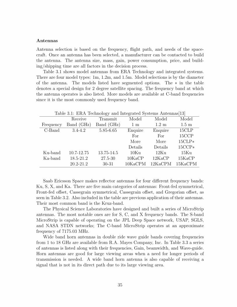
Antennas
Antenna selection is based on the frequency, flight path, and needs of the space-craft. Once an antenna has been selected, a manufacturer can be contacted to buildthe antenna. The antenna size, mass, gain, power consumption, price, and build-ing/shipping time are all factors in the decision process.
Table 3.1 shows model antennas from ERA Technology and integrated systems.There are four model types: 1m, 1.2m, and 1.5m. Model selections is by the diameterof the antenna. The models listed have segmented options. The ∗ in the tabledenotes a special design for 2 degree satellite spacing. The frequency band at whichthe antenna operates is also listed. More models are available at C-band frequenciessince it is the most commonly used frequency band.
Table 3.1: ERA Technology and Integrated Systems Antennas[13]Receive Transmit Model Model Model
Frequency Band (GHz) Band (GHz) 1 m 1.2 m 1.5 mC-Band 3.4-4.2 5.85-6.65 Enquire Enquire 15CLP
For For 15CCPMore More 15CLP∗
Details Details 15CCP∗Ku-band 10.7-12.75 13.75-14.5 10Ku 12Ku 15KuKa-band 18.5-21.2 27.5-30 10KaCP 12KaCP 15KaCP
20.2-21.2 30-31 10KaCPM 12KaCPM 15KaCPM
Saab Ericsson Space makes reflector antennas for four different frequency bands:Ku, S, X, and Ka. There are five main categories of antennas: Front-fed symmetrical,Front-fed offset, Cassegrain symmetrical, Cassegrain offset, and Gregorian offset, asseen in Table 3.2. Also included in the table are previous application of their antennas.Their most common band is the Kruz-band.
The Physical Science Laboratories have designed and built a series of MicroStripantennas. The most notable ones are for S, C, and X frequency bands. The S-bandMicroStrip is capable of operating on the JPL Deep Space network, USAP, SGLS,and NASA STDN networks; The C-band MicroStrip operates at an approximatefrequency of 7175.03 MHz.
Wide band horn antennas in double ride wave guide bands covering frequenciesfrom 1 to 18 GHz are available from R.A. Mayes Company, Inc. In Table 3.3 a seriesof antennas is listed along with their frequencies, Gain, beamwidth, and Wave-guide.Horn antennas are good for large viewing areas when a need for longer periods oftransmission is needed. A wide band horn antenna is also capable of receiving asignal that is not in its direct path due to its large viewing area.
35
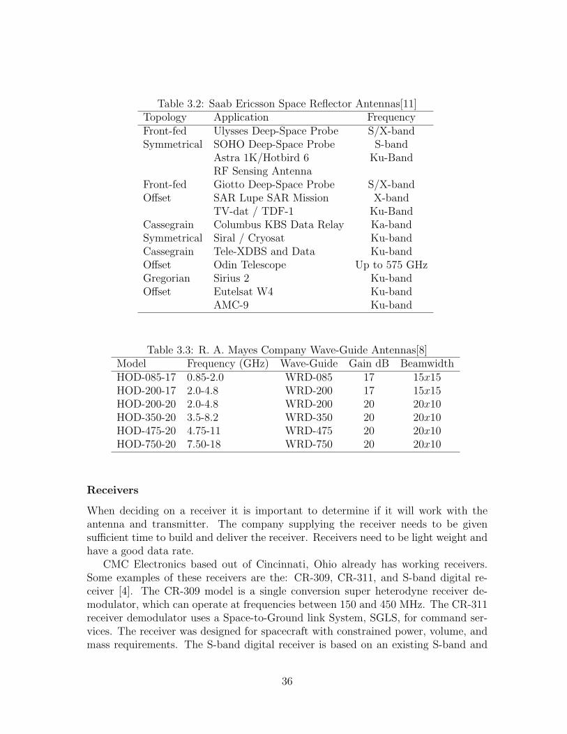
Table 3.2: Saab Ericsson Space Reflector Antennas[11]Topology Application FrequencyFront-fed Ulysses Deep-Space Probe S/X-bandSymmetrical SOHO Deep-Space Probe S-band
Astra 1K/Hotbird 6 Ku-BandRF Sensing Antenna
Front-fed Giotto Deep-Space Probe S/X-bandOffset SAR Lupe SAR Mission X-band
TV-dat / TDF-1 Ku-BandCassegrain Columbus KBS Data Relay Ka-bandSymmetrical Siral / Cryosat Ku-bandCassegrain Tele-XDBS and Data Ku-bandOffset Odin Telescope Up to 575 GHzGregorian Sirius 2 Ku-bandOffset Eutelsat W4 Ku-band
AMC-9 Ku-band
Table 3.3: R. A. Mayes Company Wave-Guide Antennas[8]Model Frequency (GHz) Wave-Guide Gain dB BeamwidthHOD-085-17 0.85-2.0 WRD-085 17 15x15HOD-200-17 2.0-4.8 WRD-200 17 15x15HOD-200-20 2.0-4.8 WRD-200 20 20x10HOD-350-20 3.5-8.2 WRD-350 20 20x10HOD-475-20 4.75-11 WRD-475 20 20x10HOD-750-20 7.50-18 WRD-750 20 20x10
Receivers
When deciding on a receiver it is important to determine if it will work with theantenna and transmitter. The company supplying the receiver needs to be givensufficient time to build and deliver the receiver. Receivers need to be light weight andhave a good data rate.
CMC Electronics based out of Cincinnati, Ohio already has working receivers.Some examples of these receivers are the: CR-309, CR-311, and S-band digital re-ceiver [4]. The CR-309 model is a single conversion super heterodyne receiver de-modulator, which can operate at frequencies between 150 and 450 MHz. The CR-311receiver demodulator uses a Space-to-Ground link System, SGLS, for command ser-vices. The receiver was designed for spacecraft with constrained power, volume, andmass requirements. The S-band digital receiver is based on an existing S-band and
36
UHF receiver products. The demodulator is implemented digitally utilizing mod-ern sampling techniques. The digital receiver is designed to for extended durationmissions.
The AeroAstro S-band receiver has a frequency range from 2025 to 2120 MHz anda mass of 165 grams [1]. A phase lock loop receiver is used for locking onto the S-bandcarrier, and a demodulator produces a base-band output. The receiver is designed tobe compatible with any spacecraft bus and consumes less than 800 mW of power.
Transmitters
Lower frequencies attenuate less in the atmosphere than high frequencies, with a lowerfrequencies a transmitter requires less power to maintain a nominal signal quality atthe receiver. Signal quality and power supply are the two most important qualitieswhen selecting a transmitter. If a poor signal is obtained more power will be neededto keep the transmitter running.
CMC Electronics makes transmitters to pair with their receivers. The C/TT-505 UHF transmitter for wireless links between two orbiting spacecraft is used forcommand telemetry. The CMC X-band modulator is a high data array phase shiftkeyed transmitter designed for use on spacecraft and satellites where large amountsof data are transmitted. The unit employs a solid state power amplifier capable ofdelivering a 25 W output.
The T-704 and T-708 are X-band transmitters for satellite data downlinks andvehicle downlinks. The T-704 is designed to transmit large volumes of payload data.The T-708 model was designed for long duration missions.
AeroAstro Corporation has S-band transmitter that was successfully launched onJune 30, 2003 aboard the Canadian Space agencies MOST mission. It provides a highpower amplifier that reaches 5 W, and is compatible with any spacecraft bus. Thisparticular model has data rates from 2 kbps to 1 kbps, with a power output from 10to 500 mW. The operating frequency is from 2200 to 2300 MHz with a mass of 180grams.
3.1.2 Link Budget Examples
Link budgets are important tools in determining the sizing of the communicationssubsystem. The link budget allows the designer or analyst to alter the sizing ofindividual communications components and view the resulting carrier-to-noise ratio.The C/N needs to be above a desired threshold decibel level in order for the signal tobe usable. The main alterables in the link budget equation are the size of the antennaon the spacecraft, the frequency used and the power output of the transponder used.The link budgets are performed for two cases: the clear air case and the bad weatheror rain case. The following are two examples each of link budgets in clear air and inrain.
37
Link Budget Example for Geostationary C-Band Satellite
The first link budget example uses a geostationary satellite that utilizes the C-bandfrequency for downlink. The satellite uses multiple transponders with bandwidth of36 MHz. The main satellite components used in this example are a satellite antennadiameter of 1 m, a transponder power output of 20 W , and a frequency of 4 GHz.The link budget table for the clear air case is shown in Table A.3. The main sectionsof the link budget table are the downlink power budget and the downlink noise powerbudget in clean air.
The C-band satellite parameters section is used for the definition of the satellitecomponents. The satellite communications components listed are the componentsthat are able to be varied. In this case, the efficiency associated with the chosenantenna is 55%. The frequencies are given as the range of values associated withthe C-band. These parameters are used to perform basic calculations in the secondsection of the table.
The basic calculations section determines several important variables. The con-version of the frequency into the wavelength is a basic calculation needed in thedetermination of the C/N ratio. The 4 GHz and the speed of light are used in Equa-tion 2.29 to determine the wavelength of 0.075 m. The total area of the antenna isdetermined using Equation 2.28. The total area is determined to be 0.785 m2 whichis used in Equation 2.27 to determine the effective antenna area. The effective areais used in the determination of the antenna gain.
The satellite interacts with a ground station on Earth. The next section of the linkbudget table includes the parameters of the Earth ground station. This spacecraft isat a distance of about 40,000 km from the ground station, which has a 5 m diameterantenna. The antenna diameter is used in Equation 2.27 to determine the antennagain from the ground station. The antenna gain from the ground station is importantin the determination of the C/N ratio of the communications link.
The downlink power budget section of the link budget is important in the deter-mination of the C/N ratio. The C/N ratio is expressed in decibels by the equation:
[C
N
]= [PR]− [PN ] (3.1)
The power received, [PR], is determined by Equation 2.4. This equation requiresthe summation of the components listed in the link budget table in the downlinkpower budget section. The transponder output backoff is set at 2 dB but is transpon-der specific. The edge of beam loss for the antenna is set at 3 dB because the signalfades at the edge of coverage. The clean air atmospheric loss is set at 0.2 dB. Otherrandom losses are included in the calculation of the power received and for this caseis set to 0.5 dB. The power received is determined to be -112.958 dB.
38
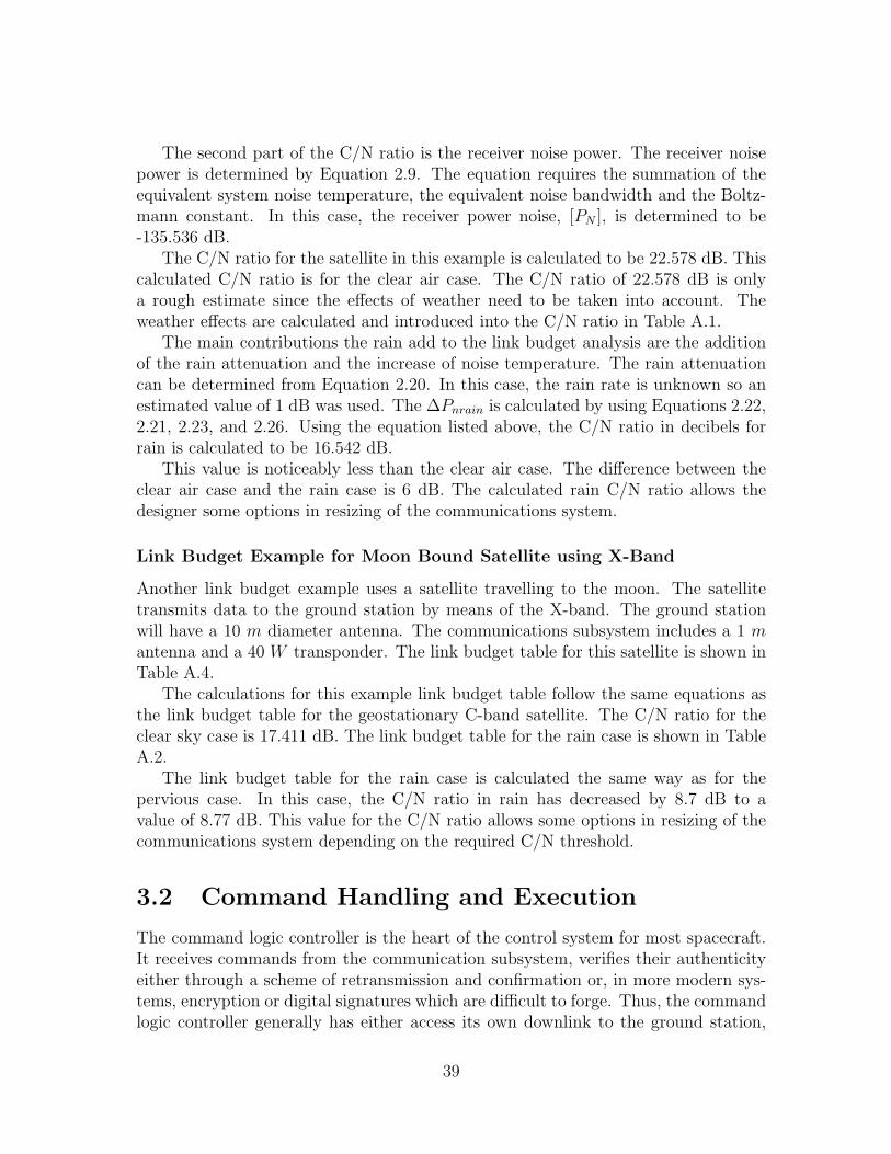
The second part of the C/N ratio is the receiver noise power. The receiver noisepower is determined by Equation 2.9. The equation requires the summation of theequivalent system noise temperature, the equivalent noise bandwidth and the Boltz-mann constant. In this case, the receiver power noise, [PN ], is determined to be-135.536 dB.
The C/N ratio for the satellite in this example is calculated to be 22.578 dB. Thiscalculated C/N ratio is for the clear air case. The C/N ratio of 22.578 dB is onlya rough estimate since the effects of weather need to be taken into account. Theweather effects are calculated and introduced into the C/N ratio in Table A.1.
The main contributions the rain add to the link budget analysis are the additionof the rain attenuation and the increase of noise temperature. The rain attenuationcan be determined from Equation 2.20. In this case, the rain rate is unknown so anestimated value of 1 dB was used. The ∆Pnrain is calculated by using Equations 2.22,2.21, 2.23, and 2.26. Using the equation listed above, the C/N ratio in decibels forrain is calculated to be 16.542 dB.
This value is noticeably less than the clear air case. The difference between theclear air case and the rain case is 6 dB. The calculated rain C/N ratio allows thedesigner some options in resizing of the communications system.
Link Budget Example for Moon Bound Satellite using X-Band
Another link budget example uses a satellite travelling to the moon. The satellitetransmits data to the ground station by means of the X-band. The ground stationwill have a 10 m diameter antenna. The communications subsystem includes a 1 mantenna and a 40 W transponder. The link budget table for this satellite is shown inTable A.4.
The calculations for this example link budget table follow the same equations asthe link budget table for the geostationary C-band satellite. The C/N ratio for theclear sky case is 17.411 dB. The link budget table for the rain case is shown in TableA.2.
The link budget table for the rain case is calculated the same way as for thepervious case. In this case, the C/N ratio in rain has decreased by 8.7 dB to avalue of 8.77 dB. This value for the C/N ratio allows some options in resizing of thecommunications system depending on the required C/N threshold.
3.2 Command Handling and Execution
The command logic controller is the heart of the control system for most spacecraft.It receives commands from the communication subsystem, verifies their authenticityeither through a scheme of retransmission and confirmation or, in more modern sys-tems, encryption or digital signatures which are difficult to forge. Thus, the commandlogic controller generally has either access its own downlink to the ground station,
39
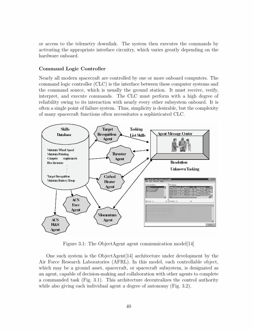
or access to the telemetry downlink. The system then executes the commands byactivating the appropriate interface circuitry, which varies greatly depending on thehardware onboard.
Command Logic Controller
Nearly all modern spacecraft are controlled by one or more onboard computers. Thecommand logic controller (CLC) is the interface between these computer systems andthe command source, which is usually the ground station. It must receive, verify,interpret, and execute commands. The CLC must perform with a high degree ofreliability owing to its interaction with nearly every other subsystem onboard. It isoften a single point of failure system. Thus, simplicity is desirable, but the complexityof many spacecraft functions often necessitates a sophisticated CLC.
Figure 3.1: The ObjectAgent agent communication model[14]
One such system is the ObjectAgent[14] architecture under development by theAir Force Research Laboratories (AFRL). In this model, each controllable object,which may be a ground asset, spacecraft, or spacecraft subsystem, is designated asan agent, capable of decision-making and collaboration with other agents to completea commanded task (Fig. 3.1). This architecture decentralizes the control authoritywhile also giving each individual agent a degree of autonomy (Fig. 3.2).
40
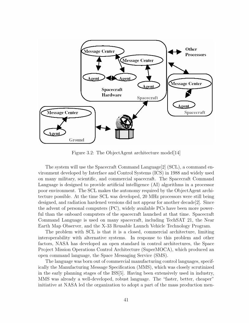
Figure 3.2: The ObjectAgent architecture model[14]
The system will use the Spacecraft Command Language[2] (SCL), a command en-vironment developed by Interface and Control Systems (ICS) in 1988 and widely usedon many military, scientific, and commercial spacecraft. The Spacecraft CommandLanguage is designed to provide artificial intelligence (AI) algorithms in a processorpoor environment. The SCL makes the autonomy required by the ObjectAgent archi-tecture possible. At the time SCL was developed, 20 MHz processors were still beingdesigned, and radiation hardened versions did not appear for another decade[2]. Sincethe advent of personal computers (PC), widely available PCs have been more power-ful than the onboard computers of the spacecraft launched at that time. SpacecraftCommand Language is used on many spacecraft, including TechSAT 21, the NearEarth Map Observer, and the X-33 Reusable Launch Vehicle Technology Program.
The problem with SCL is that it is a closed, commercial architecture, limitinginteroperability with alternative systems. In response to this problem and otherfactors, NASA has developed an open standard in control architectures, the SpaceProject Mission Operations Control Architecture (SuperMOCA), which produced anopen command language, the Space Messaging Service (SMS).
The language was born out of commercial manufacturing control languages, specif-ically the Manufacturing Message Specification (MMS), which was closely scrutinizedin the early planning stages of the ISS[5]. Having been extensively used in industry,MMS was already a well-developed, robust language. The “faster, better, cheaper”initiative at NASA led the organization to adopt a part of the mass production men-
41
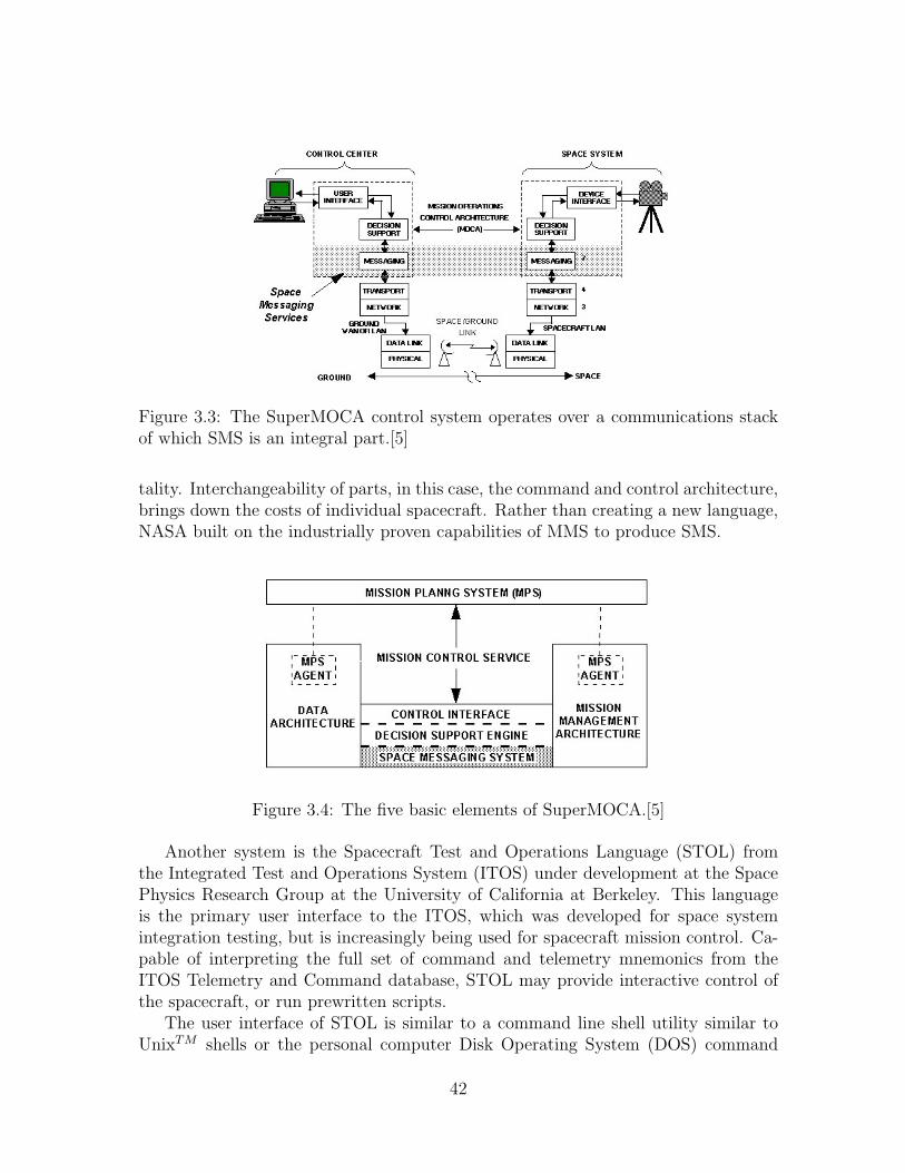
Figure 3.3: The SuperMOCA control system operates over a communications stackof which SMS is an integral part.[5]
tality. Interchangeability of parts, in this case, the command and control architecture,brings down the costs of individual spacecraft. Rather than creating a new language,NASA built on the industrially proven capabilities of MMS to produce SMS.
Figure 3.4: The five basic elements of SuperMOCA.[5]
Another system is the Spacecraft Test and Operations Language (STOL) fromthe Integrated Test and Operations System (ITOS) under development at the SpacePhysics Research Group at the University of California at Berkeley. This languageis the primary user interface to the ITOS, which was developed for space systemintegration testing, but is increasingly being used for spacecraft mission control. Ca-pable of interpreting the full set of command and telemetry mnemonics from theITOS Telemetry and Command database, STOL may provide interactive control ofthe spacecraft, or run prewritten scripts.
The user interface of STOL is similar to a command line shell utility similar toUnixTM shells or the personal computer Disk Operating System (DOS) command
42
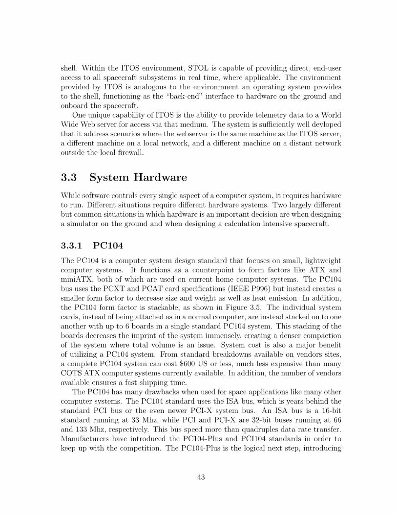
shell. Within the ITOS environment, STOL is capable of providing direct, end-useraccess to all spacecraft subsystems in real time, where applicable. The environmentprovided by ITOS is analogous to the environmnent an operating system providesto the shell, functioning as the “back-end” interface to hardware on the ground andonboard the spacecraft.
One unique capability of ITOS is the ability to provide telemetry data to a WorldWide Web server for access via that medium. The system is sufficiently well devlopedthat it address scenarios where the webserver is the same machine as the ITOS server,a different machine on a local network, and a different machine on a distant networkoutside the local firewall.
3.3 System Hardware
While software controls every single aspect of a computer system, it requires hardwareto run. Different situations require different hardware systems. Two largely differentbut common situations in which hardware is an important decision are when designinga simulator on the ground and when designing a calculation intensive spacecraft.
3.3.1 PC104
The PC104 is a computer system design standard that focuses on small, lightweightcomputer systems. It functions as a counterpoint to form factors like ATX andminiATX, both of which are used on current home computer systems. The PC104bus uses the PCXT and PCAT card specifications (IEEE P996) but instead creates asmaller form factor to decrease size and weight as well as heat emission. In addition,the PC104 form factor is stackable, as shown in Figure 3.5. The individual systemcards, instead of being attached as in a normal computer, are instead stacked on to oneanother with up to 6 boards in a single standard PC104 system. This stacking of theboards decreases the imprint of the system immensely, creating a denser compactionof the system where total volume is an issue. System cost is also a major benefitof utilizing a PC104 system. From standard breakdowns available on vendors sites,a complete PC104 system can cost $600 US or less, much less expensive than manyCOTS ATX computer systems currently available. In addition, the number of vendorsavailable ensures a fast shipping time.
The PC104 has many drawbacks when used for space applications like many othercomputer systems. The PC104 standard uses the ISA bus, which is years behind thestandard PCI bus or the even newer PCI-X system bus. An ISA bus is a 16-bitstandard running at 33 Mhz, while PCI and PCI-X are 32-bit buses running at 66and 133 Mhz, respectively. This bus speed more than quadruples data rate transfer.Manufacturers have introduced the PC104-Plus and PCI104 standards in order tokeep up with the competition. The PC104-Plus is the logical next step, introducing
43
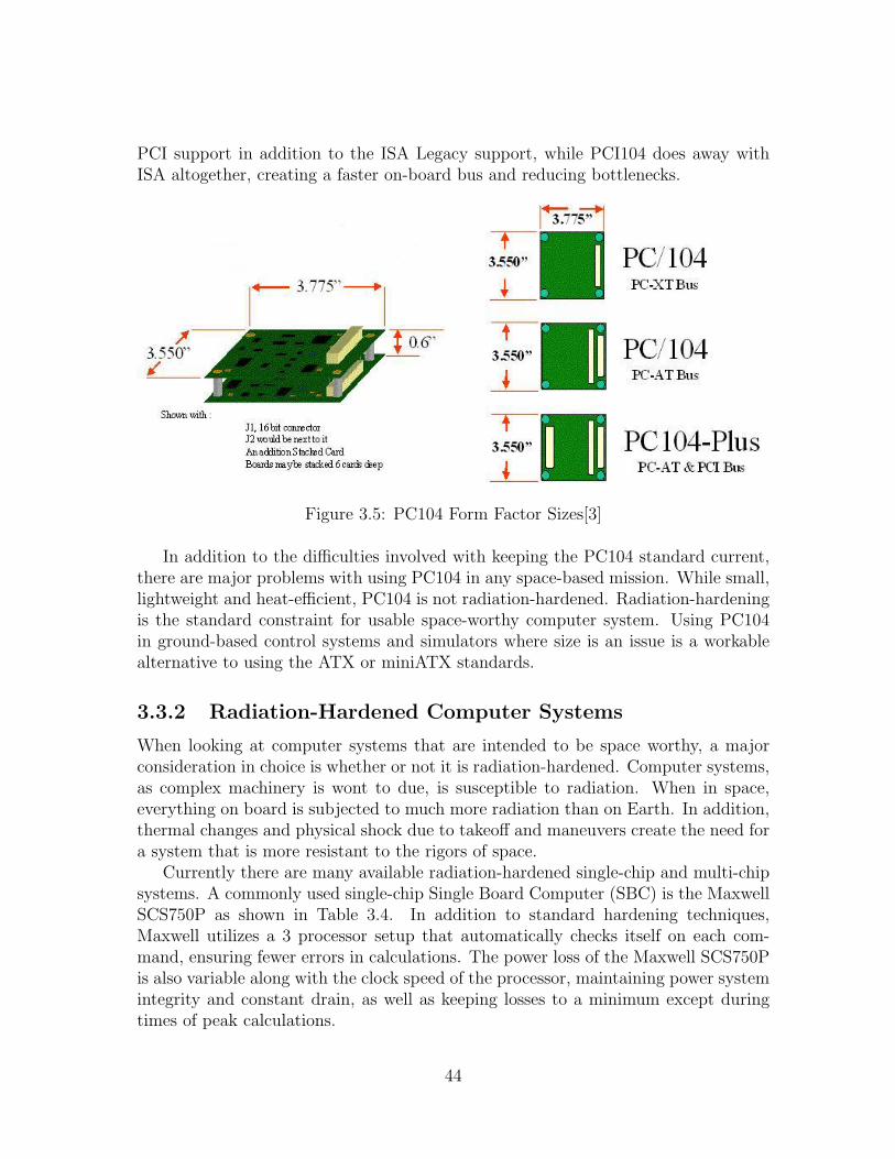
PCI support in addition to the ISA Legacy support, while PCI104 does away withISA altogether, creating a faster on-board bus and reducing bottlenecks.
Figure 3.5: PC104 Form Factor Sizes[3]
In addition to the difficulties involved with keeping the PC104 standard current,there are major problems with using PC104 in any space-based mission. While small,lightweight and heat-efficient, PC104 is not radiation-hardened. Radiation-hardeningis the standard constraint for usable space-worthy computer system. Using PC104in ground-based control systems and simulators where size is an issue is a workablealternative to using the ATX or miniATX standards.
3.3.2 Radiation-Hardened Computer Systems
When looking at computer systems that are intended to be space worthy, a majorconsideration in choice is whether or not it is radiation-hardened. Computer systems,as complex machinery is wont to due, is susceptible to radiation. When in space,everything on board is subjected to much more radiation than on Earth. In addition,thermal changes and physical shock due to takeoff and maneuvers create the need fora system that is more resistant to the rigors of space.
Currently there are many available radiation-hardened single-chip and multi-chipsystems. A commonly used single-chip Single Board Computer (SBC) is the MaxwellSCS750P as shown in Table 3.4. In addition to standard hardening techniques,Maxwell utilizes a 3 processor setup that automatically checks itself on each com-mand, ensuring fewer errors in calculations. The power loss of the Maxwell SCS750Pis also variable along with the clock speed of the processor, maintaining power systemintegrity and constant drain, as well as keeping losses to a minimum except duringtimes of peak calculations.
44
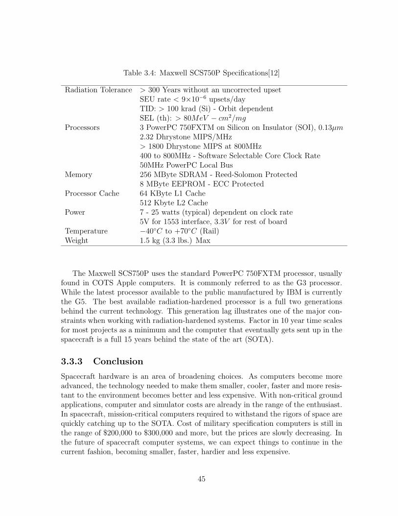
Table 3.4: Maxwell SCS750P Specifications[12]
Radiation Tolerance > 300 Years without an uncorrected upsetSEU rate < 9×10⁻⁶ upsets/dayTID: > 100 krad (Si) - Orbit dependentSEL (th): > 80MeV − cm2/mg
Processors 3 PowerPC 750FXTM on Silicon on Insulator (SOI), 0.13µm2.32 Dhrystone MIPS/MHz> 1800 Dhrystone MIPS at 800MHz400 to 800MHz - Software Selectable Core Clock Rate50MHz PowerPC Local Bus
Memory 256 MByte SDRAM - Reed-Solomon Protected8 MByte EEPROM - ECC Protected
Processor Cache 64 KByte L1 Cache512 Kbyte L2 Cache
Power 7 - 25 watts (typical) dependent on clock rate5V for 1553 interface, 3.3V for rest of board
Temperature −40◦C to +70◦C (Rail)Weight 1.5 kg (3.3 lbs.) Max
The Maxwell SCS750P uses the standard PowerPC 750FXTM processor, usuallyfound in COTS Apple computers. It is commonly referred to as the G3 processor.While the latest processor available to the public manufactured by IBM is currentlythe G5. The best available radiation-hardened processor is a full two generationsbehind the current technology. This generation lag illustrates one of the major con-straints when working with radiation-hardened systems. Factor in 10 year time scalesfor most projects as a minimum and the computer that eventually gets sent up in thespacecraft is a full 15 years behind the state of the art (SOTA).
3.3.3 Conclusion
Spacecraft hardware is an area of broadening choices. As computers become moreadvanced, the technology needed to make them smaller, cooler, faster and more resis-tant to the environment becomes better and less expensive. With non-critical groundapplications, computer and simulator costs are already in the range of the enthusiast.In spacecraft, mission-critical computers required to withstand the rigors of space arequickly catching up to the SOTA. Cost of military specification computers is still inthe range of $200,000 to $300,000 and more, but the prices are slowly decreasing. Inthe future of spacecraft computer systems, we can expect things to continue in thecurrent fashion, becoming smaller, faster, hardier and less expensive.
45
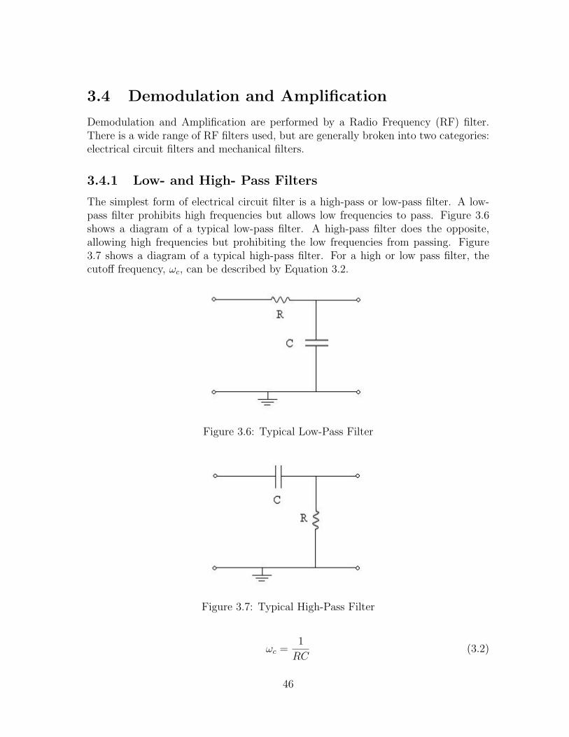
3.4 Demodulation and Amplification
Demodulation and Amplification are performed by a Radio Frequency (RF) filter.There is a wide range of RF filters used, but are generally broken into two categories:electrical circuit filters and mechanical filters.
3.4.1 Low- and High- Pass Filters
The simplest form of electrical circuit filter is a high-pass or low-pass filter. A low-pass filter prohibits high frequencies but allows low frequencies to pass. Figure 3.6shows a diagram of a typical low-pass filter. A high-pass filter does the opposite,allowing high frequencies but prohibiting the low frequencies from passing. Figure3.7 shows a diagram of a typical high-pass filter. For a high or low pass filter, thecutoff frequency, ωc, can be described by Equation 3.2.
Figure 3.6: Typical Low-Pass Filter
Figure 3.7: Typical High-Pass Filter
ωc =1
RC(3.2)
46
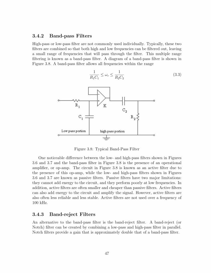
3.4.2 Band-pass Filters
High-pass or low-pass filter are not commonly used individually. Typically, these twofilters are combined so that both high and low frequencies can be filtered out, leavinga small range of frequencies that will pass through the filter. This multiple rangefiltering is known as a band-pass filter. A diagram of a band-pass filter is shown inFigure 3.8. A band-pass filter allows all frequencies within the range
1
R1C1
≤ ωc ≤1
R2C2
(3.3)
Figure 3.8: Typical Band-Pass Filter
One noticeable difference between the low- and high-pass filters shown in Figures3.6 and 3.7 and the band-pass filter in Figure 3.8 is the presence of an operationalamplifier, or op-amp. The circuit in Figure 3.8 is known as an active filter due tothe presence of this op-amp, while the low- and high-pass filters shown in Figures3.6 and 3.7 are known as passive filters. Passive filters have two major limitations:they cannot add energy to the circuit, and they perform poorly at low frequencies. Inaddition, active filters are often smaller and cheaper than passive filters. Active filterscan also add energy to the circuit and amplify the signal. However, active filters arealso often less reliable and less stable. Active filters are not used over a frequency of100 kHz.
3.4.3 Band-reject Filters
An alternative to the band-pass filter is the band-reject filter. A band-reject (orNotch) filter can be created by combining a low-pass and high-pass filter in parallel.Notch filters provide a gain that is approximately double that of a band-pass filter.
47
3.4.4 Superheterodyne Filters
Although the band-pass filter is a simple and elegant method for filtering RF carriers,another method is used more commonly due to the necessity of amplifying the signal.Because the signal strength is so low when it gets to the satellite, amplification is al-ways necessary and the Superheterodyne receiver discussed in Chapter 2 was designedto simplify this process. As described before, a local oscillator creates a secondarysignal and from which sum and difference signals can be determined. The smaller ofthe two frequencies becomes the intermediate frequency (IF) on which demodulationand amplification are then conducted. The IF is used in this process because it issmaller than the RF, making amplifiers and detectors easier to build. Typically, RFvalues will vary from 100 kHz to 30 GHz but IF values will vary from 50 to 100 kHz.
3.4.5 Mechanical Filters
Mechanical RF filters differ from electrical circuit filters in that they utilize natural,mechanical properties of materials to demodulate the incoming signal. One exampleof a mechanical filter is the crystal filter that was mentioned in Chapter 2. A crystalfilter resonates at a specified frequency and performs the low-pass and high-passfunctions naturally through mechanical vibration rather than an electrical circuit.Some other common mechanical filters are ceramic, SAW, and cavity filters.
Table 3.5: Ranges for several types of RF filtersType Frequency Range(MHz) Operating Temperature(◦C)
Bandpass 300-6000 -20 - 60Notch 400-2500 0 - 40Crystal .005-500 -30 - 75Ceramic 300-2800 -20 - 60
SAW 100-2500 -20 - 60Cavity 800-6000 15 - 40
3.4.6 Conclusion
Each of these types of filters has a range of frequencies for which it is typically used.Table 3.5 shows the ranges where each type can be used.
3.5 Conclusion
Though CC&DH systems are generally custom built for every space mission, clearlya great deal of COTS hardware is available for the individual components, and the
48
construction of a CC&DH system has largely become an exercise in sizing, equipmentselection, and assembly of existing hardware. These tasks are certainly substantial,but the engineering of custom major components for CC&DH systems is uncommon.At most, the engineer must figure out how to make a particular set of selected compo-nents interoperate, and perhaps design the interfaces. The next chapter will providea brief overview of all the subjects perviously covered as well as provide recommen-dations into areas that require future research.
49
Chapter 4
Summary and Conclusions
The CC&DH system provides all spacecraft-to-ground communications and handlesthe execution of ground commands. The composition and function of the system maybe broken up into a set of distinct categories.
4.1 Communications
The communications system is the link between the spacecraft and ground station.To complete the overall design of the communications subsystem, components such asantennas, receivers and transmitters need to be selected. These components interactwith the command and data handling subsystem.
4.1.1 Summary
The important aspects of communications sub-systems are frequency selection, an-tenna selection, transmitter selection, receiver selection, and link budget. A limitednumber of frequency bands are available for spacecraft applications, thus frequencyselection is important to the overall design of the communications systems. Regula-tion by WARC, FCC, and ITU is causing crowding of certain frequency bands. Theseorganizations have divided the world into three regions for frequency allocation. Thisfrequency crowding is leading to new experimental bands being used. The propertype and size of the antenna are two main components in antenna selection. Witha larger diameter and viewing area, an antenna can have a larger gain and higherSNR. Power requirements and mass are the main constraints with antenna selection.A few basic antennas were discussed, including reflector antennas, horn antennas,wire antennas, and antenna arrays. Transmitter and receiver selections are chosenby size, type, and gain, with the key components being the amplifiers, filters, anddemodulators. The link budget is a method used to determine the received powerand noise power in the link. Link budget calculations are done to determine thesignal quality. The link budget calculation depends on several key factors, such as;
50
transponder type, antenna alignment, antenna gain, atmospheric loses, and weatherconditions between the spacecraft and ground station.
Modeling the communications system comes down to two calculations; the SNRand the antenna gain. The SNR is a ratio of the power received to the noise power.The received power takes into account losses that occur in between the ground stationand spacecraft. Losses that occur are feeder loss, free-space spreading loss, losses dueto antenna misalignment, atmospheric absorption, and polarization mismatch loss.Antenna gain is based on the geometry of the antenna and the operating wavelength.The antenna gain is taken into account in the received power equation.
Once the signal is received from the antenna, it is demodulated and amplifiedusing an RF filter. Radio Frequency filters break down into two main categories:electrical and mechanical. Three main types of electrical RF filters are bandpass,bandreject, and superheterodyne filters. These filters are advantageous because theytend to be cheaper than mechanical filters. Four main types of mechanical filters arecrystal, ceramic, SAW, and cavity filters. Mechanical filters are advantageous becausethey tend to be simpler than electrical filters.
Each of these filters are designed to operate at a range of frequencies and selectionof particular filters will depend greatly on what frequency range is meant to be re-ceived. Another major concern when selecting the appropriate RF filter is the SNR.Some filters are capable of decreasing the SNR. This is especially important if theincoming signal needs to be amplified too much because amplification will increasethe noise received as well as the signal.
4.1.2 Future Research
In the future, research and new technologies need to focus on new frequency bands.The compromise-band is the most commonly used frequency band even though thereare multiple other frequency bands. Crowding is starting to occur in the C-band,creating a need for new frequency bands. Another important aspect in frequencyband selection is determining why people choose specific bands.
Further research is also needed on antennas, transmitters, and receivers. Thepower required to keep the antenna, receiver, and transmitter running throughoutthe duration of the mission needs to be determined. Also the cost, production time,and shipping time need to be determined for specific components. More examplesof manufacturers that supply spacecraft communications components should be in-cluded.
Further research is needed to determine the amount of data that can be sent fromthe satellite to the ground station. The amount of data that can be sent is dependenton the link budget and link margin. The amount of data that can be sent needs tobe determined from the link margin.
51
4.1.3 Conclusion
The Communications subsystem is an integral part to the day to day operations of aspace mission. Interaction between sub-systems is necessary for successful completionof the mission. Interaction is important since the antenna receives the signal thenpasses it along to other components before sending it back to a ground station.
4.2 Command and Data Handling
The command system is the heart of the spacecraft, and controls the operation ofall other subsystems. Many issues must be considered in the design of a commandsystem, including robustness, reliability, and security. Though the bulk of modernCC&DH systems are comprised mostly of COTS components, the command system,especially the software that processes commands, involves the most custom engineer-ing.
4.2.1 Reliability and Robustness
The command system is the heart of the spacecraft and the importance of robustnessin its design cannot be overstated. Whereas many bus subsystems are single pointsof failure, meaning failure jeopardizes the mission, steps can be taken to repair orbypass failures of these subsystems. However, the command subsystem is the onlysubsystem that cannot be bypassed or repaired in the event of complete failure. Inthe event of failures of the other subsystems, the task of repair or workaround fallson the command and logic system.
If an antenna fails, and the telemetry downlink and/or the command uplink arelost, the command system must act autonomously to restore communication. It musttake actions to reset or otherwise attempt to repair the failed antenna, or possiblyeven reorient the spacecraft so that another antenna may be used.
If an electric motor in an attitude control device fails, the command subsystemwill report the failure to the ground station and process the controllers’ commandsin an attempt to restart, repair, or bypass the motor. Every effort made by groundcontrollers to address the failure will ultimately be manifested as a command to thecommand system.
However, if the command system fails in such a way that it can no longer processcommands, there is no controlling system capable of carrying out repairs analogousto those just described. Without a functioning command system, no commands canbe processed. At best, the communications system may be made capable of powercycling the flight computer, but this is problematic. The communications system,even if designed to accept commands directly, lacks an authentication capability. Soenabling the system to process commands poses a security risk and the ability to powercycle the command system is clearly a major capability from a security standpoint.
52
Reliability is therefore the single most important consideration in the design of acommand system, as failure will almost certainly result in loss of the spacecraft andfailure of the mission. Thus, multiple computer command systems are not uncommon,with ultra-high reliability systems generally taking the form of multiple independentcomputers which all process the same input and vote on the resulting action. Inthe past, these systems have generally run custom-written OS’s. Tn recent years, asCOTS and Open Source OS’s have improved in robustness and computer hardwareperformance has increased, pre-existing OS’s have been used. These OS’s operatearound a kernel, which is essentially a single program run by the computer hardware.The kernel then provides the platform and multitasking environment upon which theapplication software, in this case the command logic software, may operate.
Other application software may also operate on the same OS. For instance, soft-ware to preprocess and/or compress the data stream from the payload may operateconcurrently. In earlier times, when computing power onboard spacecraft was at apremium due to the slow, power hungry systems available, data was often passeddirectly to the ground without processing. With more modern computer hardware,which can provide greater performance and consume a fraction of the power of olderhardware, the data stream may be preprocessed and compressed prior to transmis-sion, and inbound data can be encrypted because computing resources to decrypt itare available.
4.2.2 Security
Whereas older systems tended toward a model of retransmission to the ground stationto verify the authenticity of commands, newer systems increasingly rely on encrypteddata streams. In these cases, the authenticity of any command received through theencrypted data stream may be, and generally is, safely assumed.
However, the retransmission scheme is still used in some systems. Commandsreceived over the uplink are retransmitted to the ground station either through aspecial downlink, or through the telemetry downlink. The ground station analyzesthe command received and, if identical to the one transmitted, sends an executecommand, which instructs the command system to operate on the command alreadyreceived. The command is then matched against the command code table, which isgenerally not numbered consecutively so as to eliminate the possibility of single biterrors causing the system to interpret one command as another. The command isthen either executed directly by the command system, or passed on to the appropriatesubsystem, which in turn, may generate their own commands.
4.2.3 Other Issues
These internal commands are usually considered self-authenticating. An unauthenticexternal source cannot mimic an internally generated command, as the command is
53
not transmitted over a radio link, except possibly through the telemetry link to informthe ground station that it is being executed. Thus, there is no need to authenticatethese commands. The ObjectAgent architecture at AFRL is one such system whichdoes not authenticate internal commands. In this multiple agent design, every compo-nent of every asset involved in a mission is a separate agent, but interactions betweenagents on a single spacecraft may be treated differently than those transmitted acrossradio links.
4.2.4 Existing Systems
The ObjectAgent architecture uses SCL for inter-agent communication with a min-imum of computing overhead. This language was designed for the low computingpower environments of the 1980’s when 20MHz processors were still in the designphase, and is thus an efficient user of computational resources. But since SCL isa closed, proprietary language, NASA developed SuperMOCA, and the accompany-ing SMS language. Closely related to the industry proven MMS language used inindustrial automation, SMS is performance oriented but also very robust, providingmodularity to allow for new functionality rather than requiring modification to thelanguage and control architecture.
A system designed originally for a testing environment, ITOS provides the STOLlanguage, and is increasingly being used for spacecraft mission control operations.The language can accept commands using a mechanism similar to a DOS or UNIXTM
command shell, or run prewritten scripts.
4.2.5 Future Research
The fundamental aspects of command logic and handling are well-developed areas.Data encryption, in combination with increases in computing power, has simplifiedmany issues. For instance, authentication schemes involving retransmission are beingdeprecated in favor of encrypted command links. Recent advances have been madein the form of new command and control architectures. The continued developmentof these architectures promises advanced functionality for the command and controlsystem and, consequently, the entire space system.
4.3 System Hardware
While the command system is the heart of the spacecraft, the system hardware thatruns the command system, or more precisely the onboard computer control system,is the brain of the spacecraft. Without the main computer, a spacecraft cannotaccomplish anything. The system hardware, generally comprised of either solelyCOTS parts or a hybrid of COTS parts with expensive custom components, is one
54
of the last subsystems to be designed. Finalizing the design of the computer systemlast allows for a better scaling of the computer to the needs of the entire spacecraft.
4.3.1 Architecture Selection
When designing the system hardware for a spacecraft, it is necessary to develop anarchitecture to control the interaction between the processor or processors and theindividual subsystems. There are a few architecture types that are primarily used insystem design, as listed below.
• Centralized Architecture
• Ring Architecture
• Federated Bus
• Distributed Bus
While there are similarities between the four main architectures, each representsa fundamental difference in how the system can operate. Within a Centralized Ar-chitecture, every subsection interfaces directly with the central processing computer.Having a direct interface with the central processing unit prevents a failure in onesubsystem from affecting another subsystem, but because it requires that everythingbe connected to one central processor, the architecture requires more room and cancreate difficulties when attempting to add a new subsystem to an existing design.In a Ring Architecture, all subsystems are connected in a series. While connectingin a series can save space an allow for easy addition of new subsystems, if one sub-system fails then it creates the possibility that the entire spacecraft will fail. In aFederated Bus Architecture, all of the components are connected to one another andto the central processor through a common bus. Having a common bus allows foreasy troubleshooting as well as a direct path between all individual subsystems, aswell as eliminating some of the problems with the Centralized Architecture, includingdifficulties in adding new subsystems. Similar to the Federated Bus Architecture isthe Distributed Bus Architecture. In the Distributed Bus Architecture, all of thesubsystems are connected to a common bus, but the bus may have more than oneprocessor. Possessing more than one processor on a common bus allows for multiplesimultaneous command execution, but can create difficulties for testing and softwaredesign due to its complexity.
4.3.2 Interface Circuitry
Just as important as controlling and deciding which commands to execute is relayingthose commands to the various subsystems. Without the proper interface circuitry,commands from the central processor will never execute correctly. There are fourmajor command types that a spacecraft can utilize to relay its orders:
55
• Relay Commands
• Pulse Commands
• Level Commands
• Data Commands
Each type of command is used for different situations, and multiple commandtypes are generally present onboard a given spacecraft. The Relay Command is themost common command, and is onboard practically every single spacecraft launched.It is ostensibly an on/off command, turning individual subsystems either on or offor activating some automated subsystem, such as a detachment sequence. A PulseCommand is similar. It uses a small series of pulses, instead of a single pulse, toactivate either a remote relay or a logic gate. A Level Command is the same as aPulse Command, but instead of varying time duration of the pulse it varies the powerlevel. The Level Command is used mainly with logic gates, and is useful because itdoes not require a user to know the setting of the gate prior to activation. The lastcommand is a Data Command. The Data Command command sends actual datafrom one system to another using whole words. This command also uses the mostbandwidth. If one subsystem needed to send data to another subsystem or to thecontrol processor, it would utilize a Data Command.
4.3.3 Commercial Off The Shelf Computers
Selecting COTS hardware for a spacecraft is generally dependent on the availabilityspace-qualified computer equipment. While developing the architecture that a space-craft will use to communicate between the central processor and all of the subsystemsis relatively easy and can be inexpensive in terms of both time and money, it is al-most impossible to design a custom computer processor or SBC. Instead a designergenerally takes components that are readily available and assembles them in the de-sired fashion. Having to use COTS parts means that a hardware designer is limited inscope by what is currently available and tested for spacecraft. Generally it is cheapestand most effective to use a complete computer system sold COTS. Custom or hybridsystems generally have high non-recoverable costs associated with their developmentand fabrication.
4.3.4 Future Research and Recommendations
With advances in computer hardware happening at almost a daily rate, it is importantto make sure that research is done on the newest technologies in computing at the startof any new project. Research into what typically makes a processor be considered“Radiation Hardened” and what goes into creating a processor that is would also beuseful.
56
Further research should go into determining what is being used by current space-craft projects and what was used in the past. In addition, research should go intowhat other aspects of a processor are important to look at when selecting for a specificmission. Computers sometimes have variable power requirements and clock speeds,allowing for changes on the fly. Having a variable voltage requirement is most impor-tant when trying to conserve power, such as in the shadow of a planet.
Another area of future research is how to scale systems. After a spacecraft hasbeen designed, it is important to match a suitable computer to it. The individualsubsystems and programs required to run on the computer dictate how much power,in the computing sense, a processor will need. Accurate scaling equations are vitalto the design on the command system. Too few MIPS and a computer will be unableto run the spacecraft, while too many and the computer will be wasting power andmoney. A good guess is to predict the total MIPS that a given spacecraft will requireand then assume that is 70% of the total. An effective model can save millions ofdollars in a project.
4.3.5 Conclusion
When designing the hardware subsystem, there are a few key points. The systemis one of the last things to be designed on the craft to allow for proper scaling.However, it is important to have a rough understanding of what is currently availablein spacecraft computers while designing the subsystems in order to create a reasonablecomputer power demand, which helps to minimize cost.
The selection of an appropriate system architecture provides the best combinationof simplicity, modeling, flexibility and versatility for a given mission. Combined witha properly scaled computer control system and appropriate interface circuitry for com-munication with individual subsystems, costs can be minimized while performance ismaximized.
4.4 Conclusion
The first chapter established the need for the CC&DH system and defined its functionand subsystems. The issues inherent in the design of the CC&DH were discussed,and typical methods of optimizing the various subsystems were discussed.
The second chapter introduces the methods employed in the modelling and analy-sis of the CC&DH systems. Detailed description of the specific calculations performedin the analysis of potential solutions are given, and ways to address the various ob-stacles presented in some missions are discussed.
The third chapter presented a series of example solutions to the various problemsinherent in the design of CC&DH systems. Specifically, typical subsystem hardwarecomponents are presented, and existing software and system architectures are pre-sented and discussed.
57

This chapter has provided a summary of the previous three chapters, restatingthe major points covered and suggested areas for further research.
58
Bibliography
[1] AeroAstro and et al. Aeroastro home page, 2004.
[2] Brian Buckley and et al. Distributed Space-Segment Control Using SCL. Tech-nical report, Interface and Control Systems, Inc., 1998.
[3] Leroy Davis. Pc-104 bus description, 2004.
[4] CMC Electronics and et al. Cmc electronics cincinnati, 2004.
[5] Randy W. Heuser. Industrial protocols for spacecraft command and control.Technical report, Jet Propulsion Laboratory, 2000. Jet Propulsion Laboratory,http://www.sisconet.com/Scwg 15.htm.
[6] Col. John E. Keesee. Satellite Telemetry, Tracking and Control Subsystems.Technical report, Massachusetts Institue of Technology, 2003.
[7] W. J. Larson and J. R. Wertz. Space Mission Analysis and Design. McGraw-HillCompanies, Inc., 2004.
[8] R.A. Mayes and et al. R.a. mayes product news, 2004.
[9] Pisacane and Moore. Fundamentals of Space Systems. Oxford University Press,1994.
[10] Timothy Pratt. Satellite Communications. John Wiley and Sons, Inc., 2003.
[11] Saab Ericsson Space and et al. Saab ericsson space, 2004.
[12] Maxwell Technologies. Scs750atm, super computer for space specifications, 2003.
[13] ERA Technology and et al. Era technology : Antenna systems, 2004.
[14] Paul Zetocha. Satellite Cluster Command and Control. Technical report, U.S.Government, 1999. Unpublished US government document.
59
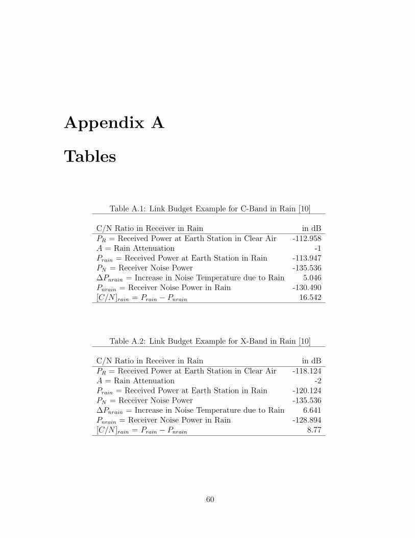
Appendix A
Tables
Table A.1: Link Budget Example for C-Band in Rain [10]
C/N Ratio in Receiver in Rain in dBPR = Received Power at Earth Station in Clear Air -112.958A = Rain Attenuation -1Prain = Received Power at Earth Station in Rain -113.947PN = Receiver Noise Power -135.536∆Pnrain = Increase in Noise Temperature due to Rain 5.046Pnrain = Receiver Noise Power in Rain -130.490[C/N ]rain = Prain − Pnrain 16.542
Table A.2: Link Budget Example for X-Band in Rain [10]
C/N Ratio in Receiver in Rain in dBPR = Received Power at Earth Station in Clear Air -118.124A = Rain Attenuation -2Prain = Received Power at Earth Station in Rain -120.124PN = Receiver Noise Power -135.536∆Pnrain = Increase in Noise Temperature due to Rain 6.641Pnrain = Receiver Noise Power in Rain -128.894[C/N ]rain = Prain − Pnrain 8.77
60
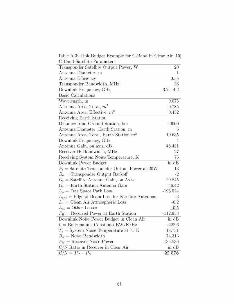
Table A.3: Link Budget Example for C-Band in Clear Air [10]C-Band Satellite ParametersTransponder Satellite Output Power, W 20Antenna Diameter, m 1Antenna Efficiency 0.55Transponder Bandwidth, MHz 36Downlink Frequency, GHz 3.7 - 4.2Basic CalculationsWavelength, m 0.075Antenna Area, Total, m2 0.785Antenna Area, Effective, m2 0.432Receiving Earth StationDistance from Ground Station, km 40000Antenna Diameter, Earth Station, m 5Antenna Area, Total, Earth Station m2 19.635Downlink Frequency, GHz 4Antenna Gain, on axis, dB 46.421Receiver IF Bandwidth, MHz 27Receiving System Noise Temperature, K 75Downlink Power Budget in dBPt = Satellite Transponder Output Power at 20W 13Bo = Transponder Output Backoff -2Gt = Satellite Antenna Gain, on Axis 29.845Gr = Earth Station Antenna Gain 46.42Lp = Free Space Path Loss -196.524Lant = Edge of Beam Loss for Satellite Antennas -3La = Clean Air Atmospheric Loss -0.2Lm = Other Losses -0.5PR = Received Power at Earth Station -112.958Downlink Noise Power Budget in Clean Air in dBk = Boltzmann’s Constant,dBW/K/Hz -228.6Ts = System Noise Temperature at 75 K 18.751Bn = Noise Bandwidth 74.313PN = Receiver Noise Power -135.536C/N Ratio in Receiver in Clear Air in dBC/N = PR − PN 22.578
61
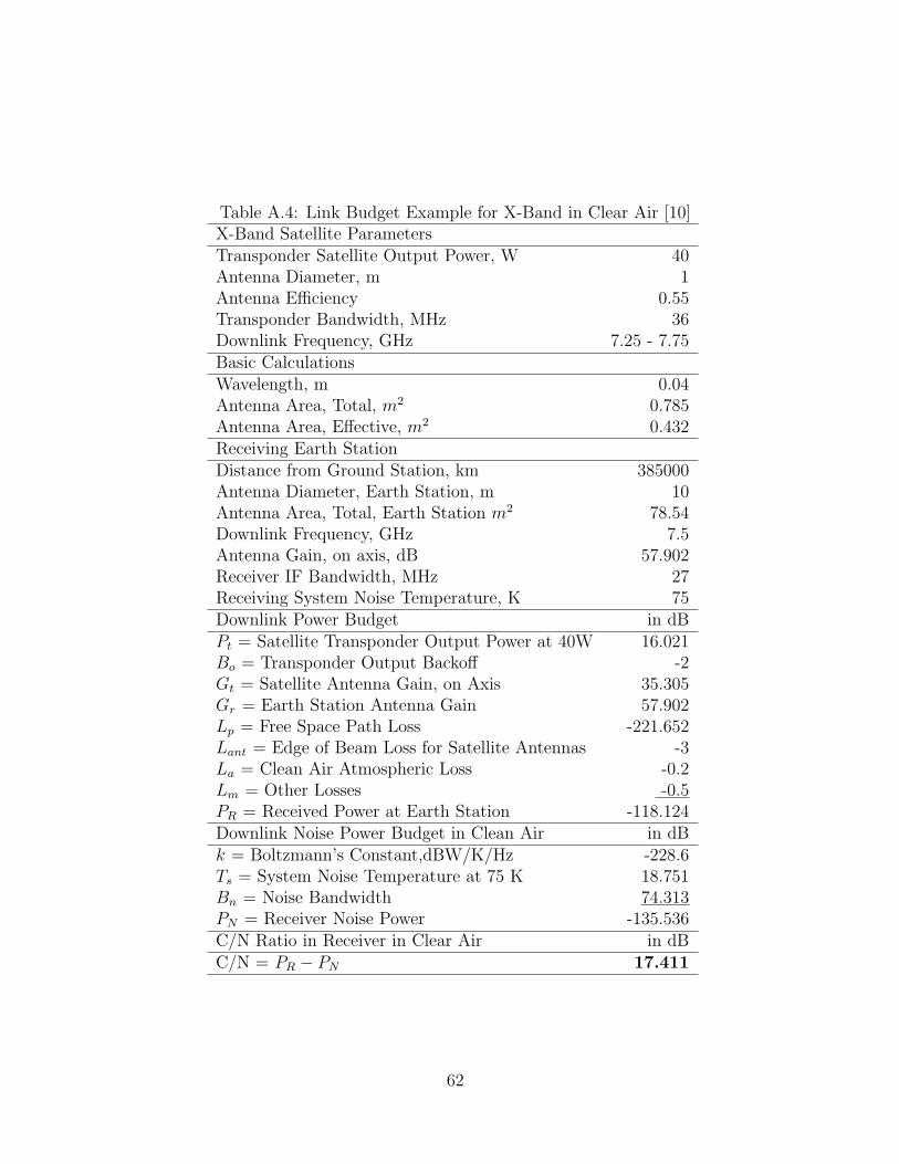
Table A.4: Link Budget Example for X-Band in Clear Air [10]X-Band Satellite ParametersTransponder Satellite Output Power, W 40Antenna Diameter, m 1Antenna Efficiency 0.55Transponder Bandwidth, MHz 36Downlink Frequency, GHz 7.25 - 7.75Basic CalculationsWavelength, m 0.04Antenna Area, Total, m2 0.785Antenna Area, Effective, m2 0.432Receiving Earth StationDistance from Ground Station, km 385000Antenna Diameter, Earth Station, m 10Antenna Area, Total, Earth Station m2 78.54Downlink Frequency, GHz 7.5Antenna Gain, on axis, dB 57.902Receiver IF Bandwidth, MHz 27Receiving System Noise Temperature, K 75Downlink Power Budget in dBPt = Satellite Transponder Output Power at 40W 16.021Bo = Transponder Output Backoff -2Gt = Satellite Antenna Gain, on Axis 35.305Gr = Earth Station Antenna Gain 57.902Lp = Free Space Path Loss -221.652Lant = Edge of Beam Loss for Satellite Antennas -3La = Clean Air Atmospheric Loss -0.2Lm = Other Losses -0.5PR = Received Power at Earth Station -118.124Downlink Noise Power Budget in Clean Air in dBk = Boltzmann’s Constant,dBW/K/Hz -228.6Ts = System Noise Temperature at 75 K 18.751Bn = Noise Bandwidth 74.313PN = Receiver Noise Power -135.536C/N Ratio in Receiver in Clear Air in dBC/N = PR − PN 17.411
62