delta motion essentials - amada weld tech
TRANSCRIPT


2/20
Table of Contents
SCOPE . . . . . . . . . . . . . . . . . . . . . . . . . . . . . . . . . . . . . . . . . . . . . . . . . . . . . . . . . . . . . . . . . . . . . . . . . . . . . . . . . 2
DELTA MOTION . . . . . . . . . . . . . . . . . . . . . . . . . . . . . . . . . . . . . . . . . . . . . . . . . . . . . . . . . . . . . . . . . . . . . . . . . . . 3
PROGRAMMING BASICS . . . . . . . . . . . . . . . . . . . . . . . . . . . . . . . . . . . . . . . . . . . . . . . . . . . . . . . . . . . . . . . . . . . . 4
WELDING EXAMPLES . . . . . . . . . . . . . . . . . . . . . . . . . . . . . . . . . . . . . . . . . . . . . . . . . . . . . . . . . . . . . . . . . . . . . . 5
TACK .NC . . . . . . . . . . . . . . . . . . . . . . . . . . . . . . . . . . . . . . . . . . . . . . . . . . . . . . . . . . . . . . . . . . . . . . . . . . . . . . . . 6
STITCH .NC . . . . . . . . . . . . . . . . . . . . . . . . . . . . . . . . . . . . . . . . . . . . . . . . . . . . . . . . . . . . . . . . . . . . . . . . . . . . . . 7
SQUARE .NC . . . . . . . . . . . . . . . . . . . . . . . . . . . . . . . . . . . . . . . . . . . . . . . . . . . . . . . . . . . . . . . . . . . . . . . . . . . . . 8
CIRCLE .NC . . . . . . . . . . . . . . . . . . . . . . . . . . . . . . . . . . . . . . . . . . . . . . . . . . . . . . . . . . . . . . . . . . . . . . . . . . . . . . 9
ROTARY .NC . . . . . . . . . . . . . . . . . . . . . . . . . . . . . . . . . . . . . . . . . . . . . . . . . . . . . . . . . . . . . . . . . . . . . . . . . . . . . 10
ROUNDED .NC . . . . . . . . . . . . . . . . . . . . . . . . . . . . . . . . . . . . . . . . . . . . . . . . . . . . . . . . . . . . . . . . . . . . . . . . . . . 11
ADVANCED PROGRAMMING USING WHILE LOOPS . . . . . . . . . . . . . . . . . . . . . . . . . . . . . . . . . . . . . . . . . . . . . . . . 12
LOOPS .NC . . . . . . . . . . . . . . . . . . . . . . . . . . . . . . . . . . . . . . . . . . . . . . . . . . . . . . . . . . . . . . . . . . . . . . . . . . . . . 13
POSITION BASED FIRING . . . . . . . . . . . . . . . . . . . . . . . . . . . . . . . . . . . . . . . . . . . . . . . . . . . . . . . . . . . . . . . . . . . 14
PBF .NC . . . . . . . . . . . . . . . . . . . . . . . . . . . . . . . . . . . . . . . . . . . . . . . . . . . . . . . . . . . . . . . . . . . . . . . . . . . . . . . . 15
HOW TO CALCULATE FEEDRATE FOR PULSED STYLE LASERS . . . . . . . . . . . . . . . . . . . . . . . . . . . . . . . . . . . . . . . 16
HOW TO CALCULATE FEEDRATE FOR CONTINUOUS STYLE LASERS . . . . . . . . . . . . . . . . . . . . . . . . . . . . . . . . . . . 17
CONVERTING LINEAR AND ROTARY MOTION . . . . . . . . . . . . . . . . . . . . . . . . . . . . . . . . . . . . . . . . . . . . . . . . . . . . 17
SEAM SEALING FORMULAS . . . . . . . . . . . . . . . . . . . . . . . . . . . . . . . . . . . . . . . . . . . . . . . . . . . . . . . . . . . . . . . . . 18
G AND M CODE GLOSSARY . . . . . . . . . . . . . . . . . . . . . . . . . . . . . . . . . . . . . . . . . . . . . . . . . . . . . . . . . . . . . . . . . 19
Scope The scope of this document is to outline many of the common practices for generating clear and effective motion programs using the Delta Motion software . A general overview of the Delta Motion software and the use of standard ‘G’ and ‘M’ codes will be followed by actual program examples for use on A-Series lasers that are used in the lab by Application Engineers to develop welding processes . Using the ideas and practices shown below in this document, you will be able to program nearly every type of weld joint configuration used in standard laser welding applications .

3/20
Delta Motion
Delta motion is the software used to parse lines of code called ‘G’ and ‘M’ codes that translate into linear or rotary motion and other essential functions on your laser welding system .
G-code, which has many variants, is the common name for the most widely used numerical control (NC) programming language . It is used mainly in computer-aided manufacturing to control automated machine tools .
M-code, or Machine code is a computer program written in machine language instructions that can be executed directly by a computer’s central processing unit (CPU) . Each instruction causes the CPU to perform a very specific task, such as open a laser shutter, turn on cover gas, or actuation of external tooling .
Using a combination of ‘G’ and ‘M’ codes, a robust program can be generated that Delta Motion reads line-by-line to execute the desired weld path and execution of desired events on your laser welding system .
1. By pressing EDIT (F2) you can access the embedded text editor inside of Delta Motion to create, edit, and save the various NC program ( .NC file) that you need to create weld paths used in production welding .
2. Current absolute machine coordinates: X axis, Y axis, Z axis and Rotary position .
3. Machine homing controls .
4. Dialogue to add NC programs into Delta Motions memory (Add) that can be pushed to the memory buffer (Download selected) and executed (Cycle Start), and MDI (Manual Data Input) to manually run lines of code without the use of an NC file .
5. Current program loaded into the memory buffer that will execute upon “Cycle Start”
See below for a screen grab of Delta Motion essential program areas .

4/20
Programming Basics
Typically, when creating a motion program, you will start by initializing the program, then setting a feed rate, which is the speed the table or rotary chuck will move . After a speed is called out, you will then need to specify if you want the machine to read absolute coordinates, or incremental coordinates . After the coordinate system is determined, you will input commands to move each axis a set distance either in a positive or negative direction . In simple X, Y, and Z movements, speeds are called out in inches per second or millimeters per second, and rotary movements are called out in degrees per second . The diagram below shows the universal coordinate system .

5/20
Welding Examples
Below are some examples of common weld joint styles, and their respective sample programs .
ADVANCED PATH*NC PROGRAM CREATED USING AN EXTERNAL CAM PROGRAM
USING ‘PBF.NC’ STYLE PROGRAM
CIRCULAR WELDCIRCLE.NC
ROUNDED CORNER WELDROUNDED.NC
SQUARE WELDSQUARE.NC
ROTARY WELDROTARY.NC
BUTT WELDSTITCH.NC

6/20
Tack.nc
The program below will open the shutter for such a short time, which will allow 1 shot to pass through to tack the part together . This is useful to automate tacking processes before welding .
open prog 31 clear ;opens the program, sets 31 for the id clears buffer .
pset x0y0z0 sets the x y and z axes to zero on machine parameters .
m53 ;sets the laser to external mode which allows control by code .
dwell100 ;delay in milliseconds necessary to allow code to execute properly .
m60 ;laser branch shutter 1 open .
dwell100 ;delay .
m10 s1 ;sets the schedule number 1 which is programmed via the laser panel .
m16 ;turns cover gas on .
dwell100 ;delay .
m54 ;turns the laser beam on fire .
dwell100 ;delay to allow tack to come through .
m55 ;turns the laser beam off .
dwell100 ;delay .
m17 ;turns cover gas off .
dwell100 ;delay .
m61 ;laser branch shutter 1 close .
dwell100 ;delay .
m52 ;sets the laser to panel control mode which allows manual control .
close ;closes the program .

7/20
Stitch.nc
Using the stitch program, the beginning of the program zeros out at your weld starting point . There is then an optional stop in which you then track to the end of the weld joint . When you start the program again, it will return to absolute home, welding the whole way back . Stitch is especially useful for welding in a straight line regardless if the part is straight to the laser head .
open prog 26 clear ;opens the program, sets 26 for the id clears buffer .
pset x0y0z0 ;sets the x y and z axes to zero on machine parameters .
m53 ;sets the laser to external mode which allows control by code .
dwell100 ;delay in milliseconds necessary to allow code to execute properly .
m60 ;laser branch shutter 1 open .
dwell100 ;delay .
m10 s5 ;sets the schedule number 5 which is programmed via the laser panel .
g90 ;sets the machine to absolute mode .
F.015 ;sets feed rate to .015 inches per second .
m16 ;turns cover gas on .
m00 ;optional stop, allows weld tracking or other inputs .
dwell100 ;delay .
m54 ;turns the laser beam on fire .
x0y0z0 ;absolute travel to origin x0,y0 z0 .
m55 ;turns the laser beam off .
dwell100 ;delay .
m17 ;turns cover gas off .
m61 ;laser branch shutter 1 close .
dwell100 ;delay .
m52 ;sets the laser to panel control mode which allows manual control .
close ;closes the program .

8/20
Square.nc
Square program will weld in a square pattern and also move 0 .25 inches past the start point for weld overlap to take place .
open prog 29 clear ;opens the program, sets 29 for the id, clears buffer .
pset x0y0z0 ;sets the x y and z axes to zero on machine parameters .
m53 ;sets the laser to external mode which allows control by code .
m60 ;laser branch shutter 1 open .
dwell100 ;delay in milliseconds necessary to allow code to execute properly .
m10 s0 ;sets the schedule number 0 which is programmed via the laser panel .
g91 ;sets the machine to incremental mode .
F.094 ;sets feed rate to .094 inches per second .
m16 ;turns cover gas on .
m54 ;turns the laser beam on fire .
x1.1748 ;moves positive in the x axis .
y-1.1748 ;moves negative in the y axis .
x-1.1748 ;moves negative in the x axis .
y1.1748 ;moves positive in the y axis .
x0.25 ;moves positive in the x axis again, for overlap .
m55 ;turns the laser beam off .
dwell100 ;delay .
m17 ;turns cover gas off .
dwell100 ;delay .
m61 ;laser branch shutter 1 close .
m52 ;sets the laser to panel control mode which allows manual control .
close ;closes the program .

9/20
Circle.nc
The circle program will move in an eccentric pattern in a radius 2 times to allow weld overlap .
open prog 95 clear ;opens the program, sets 95 for the id, clears buffer .
m53 ;sets the laser to external mode which allows control by code .
pset x0y0 ;sets the x y and z axes to zero on machine parameters .
m16 ;turns cover gas on .
f.5 ;sets feed rate to .5 inches per second .
g91 ;sets the machine to incremental mode .
f.2 ;sets feed rate to .2 inches per second .
m10 s1 ;sets the schedule number 1 which is programmed via the laser panel .
m60 ;laser branch shutter 1 open .
y.125 ;moves positive in the y axis to the top of the circle .
m00 ;optional stop, allows weld tracking or other inputs .
f.1 ;sets feed rate to .1 inches per second .
m54 ;turns the laser beam on fire .
G2 X0 Y0 I0 J-.125 ;interpolates a circle with a radius of .125 inches .
G2 X0 Y0 I0 J-.125 ;interpolates a circle with a radius of .125 inches for overlap .
m55 ;turns the laser beam off .
m61 ;laser branch shutter 1 close .
dwell100 ;delay .
m17 ;turns cover gas off .
f.5 ;sets feed rate to .5 inches per second .
g90 ;sets the machine to absolute mode .
x0y0 ;absolute travel to origin x0 y0 z0 .
m52 ;sets the laser to panel control mode which allows manual control .
close ;closes the program .
10/20
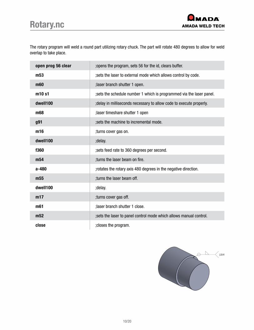
Rotary.nc
The rotary program will weld a round part utilizing rotary chuck . The part will rotate 480 degrees to allow for weld overlap to take place .
open prog 56 clear ;opens the program, sets 56 for the id, clears buffer .
m53 ;sets the laser to external mode which allows control by code .
m60 ;laser branch shutter 1 open .
m10 s1 ;sets the schedule number 1 which is programmed via the laser panel .
dwell100 ;delay in milliseconds necessary to allow code to execute properly .
m68 ;laser timeshare shutter 1 open
g91 ;sets the machine to incremental mode .
m16 ;turns cover gas on .
dwell100 ;delay .
f360 ;sets feed rate to 360 degrees per second .
m54 ;turns the laser beam on fire .
a-480 ;rotates the rotary axis 480 degrees in the negative direction .
m55 ;turns the laser beam off .
dwell100 ;delay .
m17 ;turns cover gas off .
m61 ;laser branch shutter 1 close .
m52 ;sets the laser to panel control mode which allows manual control .
close ;closes the program .
11/20
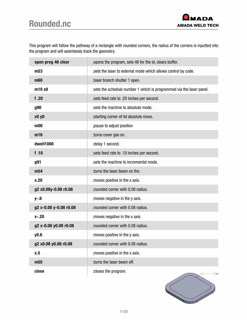
Rounded.nc
This program will follow the pathway of a rectangle with rounded corners, the radius of the corners is inputted into the program and will seamlessly track the geometry .
open prog 46 clear ;opens the program, sets 46 for the id, clears buffer .
m53 ;sets the laser to external mode which allows control by code .
m60 ;laser branch shutter 1 open .
m10 s0 ;sets the schedule number 1 which is programmed via the laser panel .
f .20 ;sets feed rate to .20 inches per second .
g90 ;sets the machine to absolute mode .
x0 y0 ;starting corner of lid absolute move .
m00 ;pause to adjust position
m16 ;turns cover gas on .
dwell1000 ;delay 1 second .
f .10 ;sets feed rate to .10 inches per second .
g91 ;sets the machine to incremental mode .
m54 ;turns the laser beam on fire .
x.20 ;moves positive in the x axis .
g2 x0.08y-0.08 r0.08 ;rounded corner with 0 .08 radius .
y-.6 ;moves negative in the y axis .
g2 x-0.08 y-0.08 r0.08 ;rounded corner with 0 .08 radius .
x-.20 ;moves negative in the x axis .
g2 x-0.08 y0.08 r0.08 ;rounded corner with 0 .08 radius .
y0.6 ;moves positive in the y axis .
g2 x0.08 y0.08 r0.08 ;rounded corner with 0 .08 radius .
x.5 ;moves positive in the x axis .
m55 ;turns the laser beam off .
close ;closes the program .

12/20
Advanced Programming Using While Loops
For more advanced programming techniques such as welding a pattern of parts laid out onto a flat plate, you can utilize variables and logic commands built into Delta Motion to create an elegant and effective program to process your parts .
Looking at the example ‘LOOPS .NC’ program on page 15, you see the following variable called out in the program on line 12, which is a counter for how many times you wish to run the loop:
p299=x
The following command starts the while loop:
while (P299>0)
This line of code tells Delta Motion execute all consecutive lines up to the endwhile function, in which it will then return back to the first line again .
The code within these bounds will continue to repeat until the decrement counter you have set reaches 0 . Once the counter reaches 0, it will pass the endwhile function and execute code below it just as it should .
You can see that every time the code executes, it passes line 23, which subtracts 1 from your p299 variable . The code will continue to run until it repeats your code the set number of times specified .
To set the number of times you wish you loop the code, you must make the previous variable of p299 = x + 1, x being the amount of times you wish the code to run within the bounds .
Multiple loops can be stacked after each other to create a program with multiple routines .

13/20
Loop.nc
open prog 1 clear ;opens the program, sets 1 for the id, clears buffer .
m53 ;sets the laser to external mode which allows control by code .
dwell100 ;delay .
m60 ;laser branch shutter 1 open .
g90 ;sets the machine to absolute mode .
f1 ;sets feed rate to 1 inches per second .
x1 y1 ;weld start position on 1st plate .
p297=.2 ;set P297 for weld diameter .
p299=7 ;set counter to number of plates +1
g91 ;sets the machine to absolute mode .
while (P299>0) ;starts a while loop as long as counter is above 0 .
m10 s1 ;sets the schedule number 1 .
f.1 ;sets feed rate to .10 inches per second .
m54 ;turns the laser beam on fire .
g2 X(P297) Y0 i(P297) j0 ;half circle movement .
m55 ;turns the laser beam off .
f1 ;sets feed rate to 1 inches per second .
x (1-p297) y0 ;offset move to next position on the plate .
m00 ;pause to line up weld .
p299=(p299-1) ;decrement counter to tell the program it has finished 1 loop .
endwhile ;end of loop function . Code will resume as normal .
m52 ;sets the laser to panel control mode manual control .
close ;closes the program .

14/20
Position Based Firing
Position based firing is an alternate mode of firing the laser, which does not rely on the pulse rate set on the laser panel, but rather a set overlap variable for center to center spacing of the weld spots . After you set a feedrate, the motion program that follows will adjust the pulses per second on the fly by modulating the frequency of the laser to accommodate table slowdowns on corners and sharp edges . This will ensure the overlap is the same on all areas of the weld .
Position based firing is initiated in the program by using the following code:
m149 s1 dxThe number input where x is, would be the center to center spot overlap .
Calculating maximum feedrate for position based firing:1. It is best practice to not exceed 90% of the machine maximum rated power .
(Spot Spacing [X]) ( Max Laser Power [Watts] ) = Maximum FeedrateEnergy [Joules]
15/20
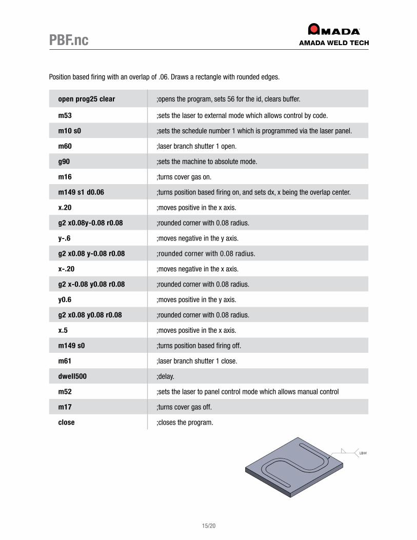
PBF.nc
Position based firing with an overlap of .06 . Draws a rectangle with rounded edges .
open prog25 clear ;opens the program, sets 56 for the id, clears buffer .
m53 ;sets the laser to external mode which allows control by code .
m10 s0 ;sets the schedule number 1 which is programmed via the laser panel .
m60 ;laser branch shutter 1 open .
g90 ;sets the machine to absolute mode .
m16 ;turns cover gas on .
m149 s1 d0.06 ;turns position based firing on, and sets dx, x being the overlap center .
x.20 ;moves positive in the x axis .
g2 x0.08y-0.08 r0.08 ;rounded corner with 0 .08 radius .
y-.6 ;moves negative in the y axis .
g2 x0.08 y-0.08 r0.08 ;rounded corner with 0 .08 radius .
x-.20 ;moves negative in the x axis .
g2 x-0.08 y0.08 r0.08 ;rounded corner with 0 .08 radius .
y0.6 ;moves positive in the y axis .
g2 x0.08 y0.08 r0.08 ;rounded corner with 0 .08 radius .
x.5 ;moves positive in the x axis .
m149 s0 ;turns position based firing off .
m61 ;laser branch shutter 1 close .
dwell500 ;delay .
m52 ;sets the laser to panel control mode which allows manual control
m17 ;turns cover gas off .
close ;closes the program .

16/20
How to Calculate Feedrate for Pulsed Style Lasers
To calculate the proper federate for your part, you must input a few variables to get accurate speed and shot count . A tool called the Weld Calculator makes these calculations easier .
1. Pulse rate (Hz) is the rate at which you want to pulse the laser during welding operation .
2. Overlap is the amount of weld spot to spot overlap you desire (80% is hermetic) .
3. Weld diameter is the size of the actual spot at the power you are using .
4. Part diameter is the diameter of the part at the weld joint interface .
Using the AMADA WELD TECH Weld Calculator, you input parameters 1-4 and on the right side, it will calculate and read out the desired federate as well as spots needed for complete joint coverage . Typically, 10 shots are added after the amount shown to allow to significant overlap of the welds .
5. Linear speed listed in inches per second .
6. Rotary speed listed in degrees per second .
7. Estimated process time in seconds to complete weld .
8. Spots needed for complete joint coverage .

17/20
How to Calculate Feedrate for Continuous Style LasersLinear welding (x, y) feed rates are a bit more flexible with continuous wave style lasers and do not rely on a given feed rate since the overlap will always be 100% . However, feed rates for rotary welds rely on a simple equation to calculate laser on time to ensure you are going around the weld joint 100% of the circumference .
Typically, the laser on time is preceded and ended with a small ramp up and ramp down of 0 .2-0 .5 seconds to reduce crater cracking and spit holes .
C = BA
Converting Linear and Rotary Motion Sometimes, when developing a motion program, you may need to convert linear motion (inches per second) to rotary motion (degrees per second) or vice versa . The following formulas and diagrams will help with these calculations .
LINEAR TO ROTARY: ROTARY TO LINEAR: A ( πB )
C = 360 C ( 360 ) A = πB

Seam Sealing Formulas
18/20
C = circumference at seam pps = pulses per second (hz)
D = diameter at seam rpm = revolutions per minute
dps = degrees per second shots = number of shots from laser
J = joules ss = spot size
OL = overlap of spots V = velocity of seam (feed rate)
pitch = step size W = wattage of laser
PL = path length wt = weld time
C = πd pps = W J
V = C wt
deg sec = 6(rpm) rpm = 60V
CV = C(rpm)
60
J = W pps
rpm = 60 wt
wt = shots pps
OL = 1 – [ V ] ss (pps)
rpm = 1 ( deg ) 6 secwt = PL V
pitch = (1-OL) ss shots = C pitch
W1(wt1) = W2(wt2)
pps = V (1-OL)ss
V = (1-OL)ss*pps

19/20
G and M Code Glossary
G CODES: G2 – circular mode (clockwise) .
G3 – circular mode (counter clockwise) .
G2/3 X0 Y0 I0 J (radius) – full circle move .
G2/3 X(diameter) Y0 I(diameter) J0 – half circle move .
G2/3 X(radius) y (radius) r(radius) – quarter circle move .
G4X(n) – time delay of n seconds .
G90 – absolute coordinate mode .
G91 – incremental coordinate mode .
M CODES: M00 – stop, which halts the machine until start is pressed .
M01 – optional stop, which halts the machine until start is pressed (if enabled) .
M02 – save position .
M03 – go to position .
M10 S(x) – reads laser parameters for schedule # x .
M16 – turn the cover gas on .
M17 – turn the cover gas off .
M52 – laser panel control mode (external control off) .
M53 – laser external mode (machine control) .
M54 – laser start (fire) .
M55 – laser stop .
M60 – laser shutter branch 1 open .
M61 – laser shutter branch 1 close .
M68 – laser timeshare shutter 1 open .
M69 – laser timeshare shutter 1 close .
M149 s1 d(x) – turns position based firing on, with a spot overlap of x .
M149 s0 – turns position based firing off .
MISCELLANEOUS CODES: dwell(x) – a time delay measured in milliseconds .
;– anything following this will be ignored and treated as a comment .
For a full list of G and M codes supported, visit the below link:
http://www .amyasupport .com/LSD/Manuals/M_and_G_Codes_20 .pdf

20/20
04/2
0
(626) 303-5676 • [email protected] • www.amadaweldtech.com Copyright© 2020 AMADA WELD TECH INC.