december 3878859r 2 - c.r. england · the registered owner, such as an international dealer, who...
TRANSCRIPT

Printed in the United States of America © 2010 Navistar, Inc. All Rights Reserved
NOTICE CALIFORNIA Be advised that this motor vehicle may be equipped with computer / recording devices. Their function is to allow an authorized individual to download data or information relating to the operation or performance of this vehicle. The stored data or information may be neither downloaded nor retrieved except by the vehicle’s registered owner, or, in the alternative, by another individual or entity authorized by the registered owner, such as an International Dealer, who may need this data or information to properly service or diagnose this vehicle for repair or following an accident. Any access to this information without the owner’s consent may be in violation of law and may subject that person or entity to criminal penalties.
Proposition 65 Warning
Diesel engine exhaust and some of its constituents are known to the State of California to cause cancer, birth defects, and other reproductive harm.
Battery posts, terminals and related accessories contain lead and lead compounds, chemicals known to the State of California to cause cancer and reproductive harm.
Wash hands after handling.
Important The information, specifications, and illustrations contained in this manual are based on data that was current at the time of publication. International reserves the right to make changes and/or improvements at any time without notification or liability, or without applying those changes or improvements to vehicles previously manufactured.
Make sure your use of this completed vehicle conforms to all federal, state and local requirements and regulations imposed on owners and operators.
PR
OSTA
R® + Series
3878859R
2 ProStar+ M
odels
Decem
ber 2010

Operator’s Manual – PROSTAR®+ Series
3878859R2
IMPORTANT IT IS IMPORTANT THAT THE VEHICLE IDENTIFICATION NUMBER (VIN), AND COMPONENT FEATURE CODE AND SERIAL NUMBERS BE RECORDED. THESE NUMBERS ARE REQUIRED TO OBTAIN INFORMATION PERTINENT TO THIS VEHICLE.
VIN (VEHICLE IDENTIFICATION
NUMBER) LOCATION LoneStar®, 9000i, ProStar®+, TranStar®, PayStar®, WorkStar®, DuraStar®, and TerraStar™ Series: Located left door opening, rear post
COMPONENT IDENTIFICATION NUMBERS
Component Feature Codes appear on the vehicle line set ticket.
Component serial numbers appear on the components.
Feature Code: Serial Number:
FRONT AXLE REAR AXLE TRANSFER CASE TRANSMISSION ENGINE
ENGINE SERIAL NUMBER LOCATION MAXXFORCE®: Stamped on pad – right side of the crankcase, below cylinder head
WORLD HEADQUARTERS Navistar, Inc. 4201 Winfield Road Warrenville, Illinois 60555 USA
INTERNATIONAL INTERNET SITE internationaltrucks.com
SALES REGIONS MIDWEST Navistar, Inc. 4201 Winfield Road PO Box 1488 Warrenville, Illinois 60555 630-753-5900 NORTHEAST Navistar, Inc. Cherry Tree Corporate Center 535 Route 38 East, Suite 300 Cherry Hill, New Jersey 08002 856-486-2300 SOUTHEAST Navistar, Inc. 2400 Commerce Avenue Building 1100, Suite 100 Duluth, Georgia 30096 678-584-2700
SOUTHWEST Navistar, Inc. 2595 Dallas Parkway, Suite 203 Frisco, Texas 75034 972-377-1200 WEST Navistar, Inc. 3017 Douglas Boulevard, Suite 300 Roseville, California 95661 916-774-7526 CANADA Navistar Canada, Inc. 5500 North Service Road – 4th Floor Box 5337 Burlington, Ontario L7L 5H7 905-332-3323 MEXICO Navistar Mexico SA DE CV Ejército Nacional 904 – 8° Piso Col, Palmas Polanco 11510 Mexico D.F. 525-262-6666 BRAZIL International Caminhões do Brasil Av. Carlos Gomes, 466 conj 1002 Bairro Auxiliadora – CEP 90480-000- Porto Alegre/RS 55 51 4009-5800
CUSTOMER ASSISTANCE CENTER 1-800-448-7825 (1-800-44-TRUCK)
Navistar, International, the International Diamond logo, with and without endorsement, ProStar, and MaxxForce are registered trademarks of Navistar, Inc., or its subsidiaries, in the United States and other countries.
All other trademarks are the property of their respective owners.

Operator’s Manual – ProStar®+ Series
Service Publications
An Operator’s Manual is shipped with this vehicle forcustomer use. Information on the purchase of other availableservice publications for this vehicle can be found on theinternationaltrucks.com Web site, or by contacting your localInternational dealer.
It is the policy of Navistar, Inc. to improve its products wheneverit is possible and practical to do so. We reserve the right to makechanges or add improvements at any time without incurring anyobligation to make such changes on products sold previously.
Operator’s Manual – ProStar®+ Series
Operator’s Manual
Form No. 3878859R2
© 2010 Navistar, Inc. All rights reserved.
3878859R2 Printed in the United States of America

Operator’s Manual – ProStar®+ Series
Printed in the United States of America 3878859R2
Table of Contents
Section 1 – Foreword
Preface. . . . . . . . . . . . . . . . . . . . . . . . . . . . . . . . . . . . . . . . . . . . . . . . . . . . . . . . . . . . . . .1Cautions and Warnings. . . . . . . . . . . . . . . . . . . . . . . . . . . . . . . . . . . . . . . . . . . . .1Assistance Guide. . . . . . . . . . . . . . . . . . . . . . . . . . . . . . . . . . . . . . . . . . . . . . . . . . . .1Component Code Numbers. . . . . . . . . . . . . . . . . . . . . . . . . . . . . . . . . . . . . . . .2
Line Set Ticket. . . . . . . . . . . . . . . . . . . . . . . . . . . . . . . . . . . . . . . . . . . . . . . . . .2Vehicle Storage Instructions. . . . . . . . . . . . . . . . . . . . . . . . . . . . . . . . . . . . . . . .2
Storage Duration - One Month or Less. . . . . . . . . . . . . . . . . . . . . . .2Storage Duration - Over One Month . . . . . . . . . . . . . . . . . . . . . . . . .3Storage Facilities . . . . . . . . . . . . . . . . . . . . . . . . . . . . . . . . . . . . . . . . . . . . . . .4
Exterior Noise Emissions. . . . . . . . . . . . . . . . . . . . . . . . . . . . . . . . . . . . . . . . . . .4Tampering with Noise Control System Prohibited. . . . . . . . . . . . . . . .4Emission Control Systems.. . . . . . . . . . . . . . . . . . . . . . . . . . . . . . . . . . . . . . . . .5Maintenance Record – Noise Control. . . . . . . . . . . . . . . . . . . . . . . . . . . . .5Reporting Safety Defects. . . . . . . . . . . . . . . . . . . . . . . . . . . . . . . . . . . . . . . . . . .5
U.S. Registered Vehicles. . . . . . . . . . . . . . . . . . . . . . . . . . . . . . . . . . . . . . .5Canadian Registered Vehicles. . . . . . . . . . . . . . . . . . . . . . . . . . . . . . . .5
Safety Recalls and Authorized Field Changes. . . . . . . . . . . . . . . . . . .5Customer Security Guide for International Trucks. . . . . . . . . . . . . . .6Optional Diamond Logic® Electronic Application Solutions. . . . .8
Section 2 – Model Description
Introduction. . . . . . . . . . . . . . . . . . . . . . . . . . . . . . . . . . . . . . . . . . . . . . . . . . . . . . . . . . .9Available Models. . . . . . . . . . . . . . . . . . . . . . . . . . . . . . . . . . . . . . . . . . . . . . . . . . . . .9Vehicle Identification. . . . . . . . . . . . . . . . . . . . . . . . . . . . . . . . . . . . . . . . . . . . . . .12
Vehicle Identification Number (VIN). . . . . . . . . . . . . . . . . . . . . . . . .12Feature Codes. . . . . . . . . . . . . . . . . . . . . . . . . . . . . . . . . . . . . . . . . . . . . . . . .12Engine Serial Number. . . . . . . . . . . . . . . . . . . . . . . . . . . . . . . . . . . . . . . .13Line Set Ticket. . . . . . . . . . . . . . . . . . . . . . . . . . . . . . . . . . . . . . . . . . . . . . . . .13
Exterior Components. . . . . . . . . . . . . . . . . . . . . . . . . . . . . . . . . . . . . . . . . . . . . .14Cab Entry and Exit. . . . . . . . . . . . . . . . . . . . . . . . . . . . . . . . . . . . . . . . . . . . . . . . .18
Hood.. . . . . . . . . . . . . . . . . . . . . . . . . . . . . . . . . . . . . . . . . . . . . . . . . . . . . . . . . . . . . . . .18Raising the Hood.. . . . . . . . . . . . . . . . . . . . . . . . . . . . . . . . . . . . . . . . . . . . .18Lowering the Hood. . . . . . . . . . . . . . . . . . . . . . . . . . . . . . . . . . . . . . . . . . . .19
Tilt-Away Bumper. . . . . . . . . . . . . . . . . . . . . . . . . . . . . . . . . . . . . . . . . . . . . . . . . .19Lowering the Tilt-Away Bumper. . . . . . . . . . . . . . . . . . . . . . . . . . . . . .20Raising the Tilt-Away Bumper. . . . . . . . . . . . . . . . . . . . . . . . . . . . . . . .20
Luggage Box Access. . . . . . . . . . . . . . . . . . . . . . . . . . . . . . . . . . . . . . . . . . . . . .21Driver and Passenger Side. . . . . . . . . . . . . . . . . . . . . . . . . . . . . . . . . . .21
Chassis Skirts. . . . . . . . . . . . . . . . . . . . . . . . . . . . . . . . . . . . . . . . . . . . . . . . . . . . . .21Removal. . . . . . . . . . . . . . . . . . . . . . . . . . . . . . . . . . . . . . . . . . . . . . . . . . . . . . . .21Installation. . . . . . . . . . . . . . . . . . . . . . . . . . . . . . . . . . . . . . . . . . . . . . . . . . . . .22Extended Chassis Skirts. . . . . . . . . . . . . . . . . . . . . . . . . . . . . . . . . . . . .22
Section 3 – Inspection Guide
Introduction. . . . . . . . . . . . . . . . . . . . . . . . . . . . . . . . . . . . . . . . . . . . . . . . . . . . . . . . .23General Information. . . . . . . . . . . . . . . . . . . . . . . . . . . . . . . . . . . . . . . . . . .23
Tractor Inspection. . . . . . . . . . . . . . . . . . . . . . . . . . . . . . . . . . . . . . . . . . . . . . . . . .24Preparation. . . . . . . . . . . . . . . . . . . . . . . . . . . . . . . . . . . . . . . . . . . . . . . . . . . .24Exterior Lights Check . . . . . . . . . . . . . . . . . . . . . . . . . . . . . . . . . . . . . . . .24Left Side Cab Area. . . . . . . . . . . . . . . . . . . . . . . . . . . . . . . . . . . . . . . . . . . .25Left Engine Compartment. . . . . . . . . . . . . . . . . . . . . . . . . . . . . . . . . . . .26Left Front of Tractor. . . . . . . . . . . . . . . . . . . . . . . . . . . . . . . . . . . . . . . . . . .27Front of Tractor. . . . . . . . . . . . . . . . . . . . . . . . . . . . . . . . . . . . . . . . . . . . . . . .29Right Front of Tractor. . . . . . . . . . . . . . . . . . . . . . . . . . . . . . . . . . . . . . . . .30Right Engine Compartment. . . . . . . . . . . . . . . . . . . . . . . . . . . . . . . . . .32Right Side of Cab. . . . . . . . . . . . . . . . . . . . . . . . . . . . . . . . . . . . . . . . . . . . .33Right Side Under Vehicle. . . . . . . . . . . . . . . . . . . . . . . . . . . . . . . . . . . . .34Right Rear of Tractor. . . . . . . . . . . . . . . . . . . . . . . . . . . . . . . . . . . . . . . . . .35Rear of Tractor. . . . . . . . . . . . . . . . . . . . . . . . . . . . . . . . . . . . . . . . . . . . . . . . .37Left Rear of Tractor. . . . . . . . . . . . . . . . . . . . . . . . . . . . . . . . . . . . . . . . . . . .38Fifth Wheel and Coupling Area. . . . . . . . . . . . . . . . . . . . . . . . . . . . . .40
3878859R2 i

Table of Contents
Cab Interior Inspection. . . . . . . . . . . . . . . . . . . . . . . . . . . . . . . . . . . . . . .41
Section 4 – Controls/Features
Introduction. . . . . . . . . . . . . . . . . . . . . . . . . . . . . . . . . . . . . . . . . . . . . . . . . . . . . . . . .43General Information. . . . . . . . . . . . . . . . . . . . . . . . . . . . . . . . . . . . . . . . . . .43Electrical. . . . . . . . . . . . . . . . . . . . . . . . . . . . . . . . . . . . . . . . . . . . . . . . . . . . . . .43Electrical System.. . . . . . . . . . . . . . . . . . . . . . . . . . . . . . . . . . . . . . . . . . . . .43
Dash Components. . . . . . . . . . . . . . . . . . . . . . . . . . . . . . . . . . . . . . . . . . . . . . . . .44Overhead Console. . . . . . . . . . . . . . . . . . . . . . . . . . . . . . . . . . . . . . . . . . . . . . . . .45Instrument Panel Gauge Cluster. . . . . . . . . . . . . . . . . . . . . . . . . . . . . . . . .46
Warning Indicators. . . . . . . . . . . . . . . . . . . . . . . . . . . . . . . . . . . . . . . . . . . .48Gauges. . . . . . . . . . . . . . . . . . . . . . . . . . . . . . . . . . . . . . . . . . . . . . . . . . . . . . . . .50Instrument Panel Gauge Cluster Alarms. . . . . . . . . . . . . . . . . . .52Direct Drive Warning Indicators. . . . . . . . . . . . . . . . . . . . . . . . . . . . . .54Integral Digital Display. . . . . . . . . . . . . . . . . . . . . . . . . . . . . . . . . . . . . . . .54General Text and Warning Messages. . . . . . . . . . . . . . . . . . . . . . .56Optional Instrument panel gauge cluster CompassCalibration Procedure. . . . . . . . . . . . . . . . . . . . . . . . . . . . . . . . . . . . . . . . .57Compass Declination Zone Set Procedure. . . . . . . . . . . . . . . . .57Compass Directional Calibration Procedure. . . . . . . . . . . . . . .60Integral Digital Display Detailed Information. . . . . . . . . . . . . . . .62Switches. . . . . . . . . . . . . . . . . . . . . . . . . . . . . . . . . . . . . . . . . . . . . . . . . . . . . . . .75Headlights. . . . . . . . . . . . . . . . . . . . . . . . . . . . . . . . . . . . . . . . . . . . . . . . . . . . . .75Daytime Running Lights (DRL). . . . . . . . . . . . . . . . . . . . . . . . . . . . . .75Lights On With Wipers. . . . . . . . . . . . . . . . . . . . . . . . . . . . . . . . . . . . . . . .75Park Lights. . . . . . . . . . . . . . . . . . . . . . . . . . . . . . . . . . . . . . . . . . . . . . . . . . . . .75Panel Lighting. . . . . . . . . . . . . . . . . . . . . . . . . . . . . . . . . . . . . . . . . . . . . . . . .75Dome Lighting. . . . . . . . . . . . . . . . . . . . . . . . . . . . . . . . . . . . . . . . . . . . . . . . .76Courtesy Lights. . . . . . . . . . . . . . . . . . . . . . . . . . . . . . . . . . . . . . . . . . . . . . . .76
Steering Wheel Controls. . . . . . . . . . . . . . . . . . . . . . . . . . . . . . . . . . . . . . . . . .77Cruise Control. . . . . . . . . . . . . . . . . . . . . . . . . . . . . . . . . . . . . . . . . . . . . . . . .78
Steering Column and Switches. . . . . . . . . . . . . . . . . . . . . . . . . . . . . . . . . . .78Center Dash Panel/Wing Panel. . . . . . . . . . . . . . . . . . . . . . . . . . . . . . . . . . .81
Gauges. . . . . . . . . . . . . . . . . . . . . . . . . . . . . . . . . . . . . . . . . . . . . . . . . . . . . . . . .82Switches. . . . . . . . . . . . . . . . . . . . . . . . . . . . . . . . . . . . . . . . . . . . . . . . . . . . . . . .82Climate Control. . . . . . . . . . . . . . . . . . . . . . . . . . . . . . . . . . . . . . . . . . . . . . . .86Air Conditioning. . . . . . . . . . . . . . . . . . . . . . . . . . . . . . . . . . . . . . . . . . . . . . .88Dehumidification. . . . . . . . . . . . . . . . . . . . . . . . . . . . . . . . . . . . . . . . . . . . . . .89
Electronic Vehicle Monitoring. . . . . . . . . . . . . . . . . . . . . . . . . . . . . . . . . . . . .89Base Display. . . . . . . . . . . . . . . . . . . . . . . . . . . . . . . . . . . . . . . . . . . . . . . . . . .89Premium Display. . . . . . . . . . . . . . . . . . . . . . . . . . . . . . . . . . . . . . . . . . . . . .89
SmartWave® Display. . . . . . . . . . . . . . . . . . . . . . . . . . . . . . . . . . . . . . . . . . . . . .89Door and Window Controls. . . . . . . . . . . . . . . . . . . . . . . . . . . . . . . . . . . . . . .90
Door Lock/Unlock. . . . . . . . . . . . . . . . . . . . . . . . . . . . . . . . . . . . . . . . . . . . .90Cab Doors and Locks. . . . . . . . . . . . . . . . . . . . . . . . . . . . . . . . . . . . . . . . .90Remote Keyless Entry Operation (Optional). . . . . . . . . . . . . . .90Lock/Unlock From Interior. . . . . . . . . . . . . . . . . . . . . . . . . . . . . . . . . . . .91Automatic Door Lock Function. . . . . . . . . . . . . . . . . . . . . . . . . . . . . . .91Driver/Passenger Windows. . . . . . . . . . . . . . . . . . . . . . . . . . . . . . . . . .91Manual Operation. . . . . . . . . . . . . . . . . . . . . . . . . . . . . . . . . . . . . . . . . . . . .91Power Operation. . . . . . . . . . . . . . . . . . . . . . . . . . . . . . . . . . . . . . . . . . . . . .92Window Lockout Function. . . . . . . . . . . . . . . . . . . . . . . . . . . . . . . . . . . .92Mirror Controls. . . . . . . . . . . . . . . . . . . . . . . . . . . . . . . . . . . . . . . . . . . . . . . . .92Vent Window.. . . . . . . . . . . . . . . . . . . . . . . . . . . . . . . . . . . . . . . . . . . . . . . . . .92
Eaton VORAD Collision Warning System (Optional). . . . . . . . . . .93System Description. . . . . . . . . . . . . . . . . . . . . . . . . . . . . . . . . . . . . . . . . . .93Driver Reward. . . . . . . . . . . . . . . . . . . . . . . . . . . . . . . . . . . . . . . . . . . . . . . . .93
Section 5 – Sleeper Features
Introduction. . . . . . . . . . . . . . . . . . . . . . . . . . . . . . . . . . . . . . . . . . . . . . . . . . . . . . . . .95General Information. . . . . . . . . . . . . . . . . . . . . . . . . . . . . . . . . . . . . . . . . . .95Main Features. . . . . . . . . . . . . . . . . . . . . . . . . . . . . . . . . . . . . . . . . . . . . . . . .95
ii 3878859R2

Table of Contents
Lighting. . . . . . . . . . . . . . . . . . . . . . . . . . . . . . . . . . . . . . . . . . . . . . . . . . . . . . . . . . . . . .97Dome Light. . . . . . . . . . . . . . . . . . . . . . . . . . . . . . . . . . . . . . . . . . . . . . . . . . . . .97Reading Lights. . . . . . . . . . . . . . . . . . . . . . . . . . . . . . . . . . . . . . . . . . . . . . . .97Floor Lights. . . . . . . . . . . . . . . . . . . . . . . . . . . . . . . . . . . . . . . . . . . . . . . . . . . .97Accent Lights. . . . . . . . . . . . . . . . . . . . . . . . . . . . . . . . . . . . . . . . . . . . . . . . . .97
Sleeper Control Panel. . . . . . . . . . . . . . . . . . . . . . . . . . . . . . . . . . . . . . . . . . . . .98General Information. . . . . . . . . . . . . . . . . . . . . . . . . . . . . . . . . . . . . . . . . . .98Accent Light Dimmer Switch. . . . . . . . . . . . . . . . . . . . . . . . . . . . . . . . .99Accent Light Switch. . . . . . . . . . . . . . . . . . . . . . . . . . . . . . . . . . . . . . . . . . .99Sleeper Dome/Floor Light Switch. . . . . . . . . . . . . . . . . . . . . . . . . . .99Engine Control Switch. . . . . . . . . . . . . . . . . . . . . . . . . . . . . . . . . . . . . . . .99Manual Climate Controls. . . . . . . . . . . . . . . . . . . . . . . . . . . . . . . . . . . .100Electronic Climate Controller. . . . . . . . . . . . . . . . . . . . . . . . . . . . . . .100Power Receptacle. . . . . . . . . . . . . . . . . . . . . . . . . . . . . . . . . . . . . . . . . . .101Radio Remote Control. . . . . . . . . . . . . . . . . . . . . . . . . . . . . . . . . . . . . .101Remote Power Inverter Panel. . . . . . . . . . . . . . . . . . . . . . . . . . . . . .101
Windows.. . . . . . . . . . . . . . . . . . . . . . . . . . . . . . . . . . . . . . . . . . . . . . . . . . . . . . . . . .102General Information. . . . . . . . . . . . . . . . . . . . . . . . . . . . . . . . . . . . . . . . .102
Bunk Restraint System.. . . . . . . . . . . . . . . . . . . . . . . . . . . . . . . . . . . . . . . . . .103General Information. . . . . . . . . . . . . . . . . . . . . . . . . . . . . . . . . . . . . . . . .103Adjustable Belts. . . . . . . . . . . . . . . . . . . . . . . . . . . . . . . . . . . . . . . . . . . . . .103Restraint Webbing System. . . . . . . . . . . . . . . . . . . . . . . . . . . . . . . . .103
Lower Bunk. . . . . . . . . . . . . . . . . . . . . . . . . . . . . . . . . . . . . . . . . . . . . . . . . . . . . . . .105General Information. . . . . . . . . . . . . . . . . . . . . . . . . . . . . . . . . . . . . . . . .105
Upper Bunk. . . . . . . . . . . . . . . . . . . . . . . . . . . . . . . . . . . . . . . . . . . . . . . . . . . . . . .106General Information. . . . . . . . . . . . . . . . . . . . . . . . . . . . . . . . . . . . . . . . .106Entering The Upper Bunk. . . . . . . . . . . . . . . . . . . . . . . . . . . . . . . . . . .107Exiting The Upper Bunk. . . . . . . . . . . . . . . . . . . . . . . . . . . . . . . . . . . . .108
Cabinets/Storage. . . . . . . . . . . . . . . . . . . . . . . . . . . . . . . . . . . . . . . . . . . . . . . . .109General Information. . . . . . . . . . . . . . . . . . . . . . . . . . . . . . . . . . . . . . . . .109
Cabinets. . . . . . . . . . . . . . . . . . . . . . . . . . . . . . . . . . . . . . . . . . . . . . . . . . . . . . . . . . .110Refrigerator Cabinet. . . . . . . . . . . . . . . . . . . . . . . . . . . . . . . . . . . . . . . . .110
Horizontal Refrigerator. . . . . . . . . . . . . . . . . . . . . . . . . . . . . . . . . . . . . .111Dresser Cabinet. . . . . . . . . . . . . . . . . . . . . . . . . . . . . . . . . . . . . . . . . . . . . .111Tower Wardrobe Cabinet. . . . . . . . . . . . . . . . . . . . . . . . . . . . . . . . . . . .112Rear Wardrobe Cabinet. . . . . . . . . . . . . . . . . . . . . . . . . . . . . . . . . . . . .113Airline Cabinets. . . . . . . . . . . . . . . . . . . . . . . . . . . . . . . . . . . . . . . . . . . . . .114
Convenience Features. . . . . . . . . . . . . . . . . . . . . . . . . . . . . . . . . . . . . . . . . . .115General Information. . . . . . . . . . . . . . . . . . . . . . . . . . . . . . . . . . . . . . . . .115Sleeper Curtain. . . . . . . . . . . . . . . . . . . . . . . . . . . . . . . . . . . . . . . . . . . . . .115Television Mount. . . . . . . . . . . . . . . . . . . . . . . . . . . . . . . . . . . . . . . . . . . . .115Power Inverter. . . . . . . . . . . . . . . . . . . . . . . . . . . . . . . . . . . . . . . . . . . . . . . .115Power Sockets. . . . . . . . . . . . . . . . . . . . . . . . . . . . . . . . . . . . . . . . . . . . . . .115Speakers. . . . . . . . . . . . . . . . . . . . . . . . . . . . . . . . . . . . . . . . . . . . . . . . . . . . . .115Floor Covering. . . . . . . . . . . . . . . . . . . . . . . . . . . . . . . . . . . . . . . . . . . . . . .115Sleeper Fan. . . . . . . . . . . . . . . . . . . . . . . . . . . . . . . . . . . . . . . . . . . . . . . . . .115
Section 6 – Operation
Operation Safety. . . . . . . . . . . . . . . . . . . . . . . . . . . . . . . . . . . . . . . . . . . . . . . . . .117General Information. . . . . . . . . . . . . . . . . . . . . . . . . . . . . . . . . . . . . . . . .117Cab Controls. . . . . . . . . . . . . . . . . . . . . . . . . . . . . . . . . . . . . . . . . . . . . . . . .118
Seat Belts. . . . . . . . . . . . . . . . . . . . . . . . . . . . . . . . . . . . . . . . . . . . . . . . . . . . . . . . .118General Information. . . . . . . . . . . . . . . . . . . . . . . . . . . . . . . . . . . . . . . . .118General Information. . . . . . . . . . . . . . . . . . . . . . . . . . . . . . . . . . . . . . . . .119Operation. . . . . . . . . . . . . . . . . . . . . . . . . . . . . . . . . . . . . . . . . . . . . . . . . . . . .119Care of Seat Belts. . . . . . . . . . . . . . . . . . . . . . . . . . . . . . . . . . . . . . . . . . .120
Seats. . . . . . . . . . . . . . . . . . . . . . . . . . . . . . . . . . . . . . . . . . . . . . . . . . . . . . . . . . . . . . .121General Information. . . . . . . . . . . . . . . . . . . . . . . . . . . . . . . . . . . . . . . . .121
Starting Procedures. . . . . . . . . . . . . . . . . . . . . . . . . . . . . . . . . . . . . . . . . . . . . .123General Information. . . . . . . . . . . . . . . . . . . . . . . . . . . . . . . . . . . . . . . . .123Engine Starting. . . . . . . . . . . . . . . . . . . . . . . . . . . . . . . . . . . . . . . . . . . . . .123After the Engine Starts. . . . . . . . . . . . . . . . . . . . . . . . . . . . . . . . . . . . . .124Engine Shutdown. . . . . . . . . . . . . . . . . . . . . . . . . . . . . . . . . . . . . . . . . . . .124
3878859R2 iii

Table of Contents
Emergency Starting. . . . . . . . . . . . . . . . . . . . . . . . . . . . . . . . . . . . . . . . .124Cold Weather. . . . . . . . . . . . . . . . . . . . . . . . . . . . . . . . . . . . . . . . . . . . . . . . .125General Information. . . . . . . . . . . . . . . . . . . . . . . . . . . . . . . . . . . . . . . . .125Cold Weather Starting. . . . . . . . . . . . . . . . . . . . . . . . . . . . . . . . . . . . . . .125Cold Weather Operation. . . . . . . . . . . . . . . . . . . . . . . . . . . . . . . . . . . .126Engine Idling . . . . . . . . . . . . . . . . . . . . . . . . . . . . . . . . . . . . . . . . . . . . . . . . .126Engine Idle Shutdown Timer (Optional). . . . . . . . . . . . . . . . . . .127Winter Front Usage.. . . . . . . . . . . . . . . . . . . . . . . . . . . . . . . . . . . . . . . . .127Hot Weather Operation. . . . . . . . . . . . . . . . . . . . . . . . . . . . . . . . . . . . . .127
Operating Instructions. . . . . . . . . . . . . . . . . . . . . . . . . . . . . . . . . . . . . . . . . . . .128General Information. . . . . . . . . . . . . . . . . . . . . . . . . . . . . . . . . . . . . . . . .128Steering. . . . . . . . . . . . . . . . . . . . . . . . . . . . . . . . . . . . . . . . . . . . . . . . . . . . . . .128Adjustable Steering Column.. . . . . . . . . . . . . . . . . . . . . . . . . . . . . . .129General Information. . . . . . . . . . . . . . . . . . . . . . . . . . . . . . . . . . . . . . . . .129Electrical. . . . . . . . . . . . . . . . . . . . . . . . . . . . . . . . . . . . . . . . . . . . . . . . . . . . . .130Alternator. . . . . . . . . . . . . . . . . . . . . . . . . . . . . . . . . . . . . . . . . . . . . . . . . . . . .130Battery. . . . . . . . . . . . . . . . . . . . . . . . . . . . . . . . . . . . . . . . . . . . . . . . . . . . . . . .130BATTERY ON Indicator. . . . . . . . . . . . . . . . . . . . . . . . . . . . . . . . . . . . .131Circuit Breakers, Fuses and Fusible Links. . . . . . . . . . . . . . . .131Electrical Load Control and Shedding (ELCS). . . . . . . . . . . .132Engine. . . . . . . . . . . . . . . . . . . . . . . . . . . . . . . . . . . . . . . . . . . . . . . . . . . . . . . .132Charge Air Cooler. . . . . . . . . . . . . . . . . . . . . . . . . . . . . . . . . . . . . . . . . . .132Electronic Engine Controller. . . . . . . . . . . . . . . . . . . . . . . . . . . . . . . .133Engine Brake. . . . . . . . . . . . . . . . . . . . . . . . . . . . . . . . . . . . . . . . . . . . . . . . .133MaxxForce® 11, 13 and 15 Engine Brake WithEaton AutoShift®/UltraShift® TransmissionsSpecial Driver Instructions. . . . . . . . . . . . . . . . . . . . . . . . . . . . . . . . . .133MaxxForce® Engine Features. . . . . . . . . . . . . . . . . . . . . . . . . . . . . .134Certified Clean Idle. . . . . . . . . . . . . . . . . . . . . . . . . . . . . . . . . . . . . . . . . .134Self Diagnostics. . . . . . . . . . . . . . . . . . . . . . . . . . . . . . . . . . . . . . . . . . . . . .134Air Compressor Cycling. . . . . . . . . . . . . . . . . . . . . . . . . . . . . . . . . . . . .135Cooling System.. . . . . . . . . . . . . . . . . . . . . . . . . . . . . . . . . . . . . . . . . . . . .135
Engine Oil. . . . . . . . . . . . . . . . . . . . . . . . . . . . . . . . . . . . . . . . . . . . . . . . . . . .136Engine Performance Problems.. . . . . . . . . . . . . . . . . . . . . . . . . . . .136Fuel. . . . . . . . . . . . . . . . . . . . . . . . . . . . . . . . . . . . . . . . . . . . . . . . . . . . . . . . . . . .137Ultra Low Sulfur Diesel Fuel Requirements. . . . . . . . . . . . . . .137Unacceptable Fuel Blends. . . . . . . . . . . . . . . . . . . . . . . . . . . . . . . . . .137Hazards of Diesel Fuel/Gasoline Blends. . . . . . . . . . . . . . . . . .137Additional Unsafe Practices. . . . . . . . . . . . . . . . . . . . . . . . . . . . . . . .137Fuel and Lubricant Additives. . . . . . . . . . . . . . . . . . . . . . . . . . . . . . .137Fueling Procedures. . . . . . . . . . . . . . . . . . . . . . . . . . . . . . . . . . . . . . . . . .137Fueling Precautions. . . . . . . . . . . . . . . . . . . . . . . . . . . . . . . . . . . . . . . . .138Reserve Fuel. . . . . . . . . . . . . . . . . . . . . . . . . . . . . . . . . . . . . . . . . . . . . . . . .138Exhaust Diesel Particulate Filter Regeneration. . . . . . . . . . .139Parked Regeneration Procedure. . . . . . . . . . . . . . . . . . . . . . . . . . .141Regeneration Inhibit Switch. . . . . . . . . . . . . . . . . . . . . . . . . . . . . . . .141Two-Position Regeneration Inhibit Switch. . . . . . . . . . . . . . . . .142Three-Position Regeneration Inhibit Switch. . . . . . . . . . . . . . .142Transmission. . . . . . . . . . . . . . . . . . . . . . . . . . . . . . . . . . . . . . . . . . . . . . . . .142Manual Transmissions. . . . . . . . . . . . . . . . . . . . . . . . . . . . . . . . . . . . . . .142Engaging the Clutch. . . . . . . . . . . . . . . . . . . . . . . . . . . . . . . . . . . . . . . . .143Hydraulic Clutch Actuation System. . . . . . . . . . . . . . . . . . . . . . . .144Double Clutch Procedures. . . . . . . . . . . . . . . . . . . . . . . . . . . . . . . . . .145Clutch Precautions. . . . . . . . . . . . . . . . . . . . . . . . . . . . . . . . . . . . . . . . . .145Eaton AutoShift® Transmissions (Optional). . . . . . . . . . . . . . .146Eaton UltraShift® Transmissions (Optional). . . . . . . . . . . . . .148Clutch Brake. . . . . . . . . . . . . . . . . . . . . . . . . . . . . . . . . . . . . . . . . . . . . . . . . .148Power Take-off Control. . . . . . . . . . . . . . . . . . . . . . . . . . . . . . . . . . . . . .148Rear Axles . . . . . . . . . . . . . . . . . . . . . . . . . . . . . . . . . . . . . . . . . . . . . . . . . . .148Locking or Limited Slip Differentials. . . . . . . . . . . . . . . . . . . . . . .148Tandem Axle Power Divider Lock (PDL) Control. . . . . . . . .149Driver Controlled Differential Lock. . . . . . . . . . . . . . . . . . . . . . . . .150Rear Suspension. . . . . . . . . . . . . . . . . . . . . . . . . . . . . . . . . . . . . . . . . . . .150Rear Air Ride Suspension. . . . . . . . . . . . . . . . . . . . . . . . . . . . . . . . . .150
iv 3878859R2

Table of Contents
Rear Air Suspension Air Dump.. . . . . . . . . . . . . . . . . . . . . . . . . . . .150Air Suspension System Faults. . . . . . . . . . . . . . . . . . . . . . . . . . . . . .151
Brakes. . . . . . . . . . . . . . . . . . . . . . . . . . . . . . . . . . . . . . . . . . . . . . . . . . . . . . . . . . . . .151General Information. . . . . . . . . . . . . . . . . . . . . . . . . . . . . . . . . . . . . . . . .151Downhill Operation. . . . . . . . . . . . . . . . . . . . . . . . . . . . . . . . . . . . . . . . . .152Air Brakes. . . . . . . . . . . . . . . . . . . . . . . . . . . . . . . . . . . . . . . . . . . . . . . . . . . . .152General Information. . . . . . . . . . . . . . . . . . . . . . . . . . . . . . . . . . . . . . . . .152Air Gauge, Low Air Pressure Beeper and WarningIndicator. . . . . . . . . . . . . . . . . . . . . . . . . . . . . . . . . . . . . . . . . . . . . . . . . . . . . . .153Reservoir Moisture Draining. . . . . . . . . . . . . . . . . . . . . . . . . . . . . . . .153Brake Application. . . . . . . . . . . . . . . . . . . . . . . . . . . . . . . . . . . . . . . . . . . .154Parking Brake. . . . . . . . . . . . . . . . . . . . . . . . . . . . . . . . . . . . . . . . . . . . . . . .154Parking Brake Reset. . . . . . . . . . . . . . . . . . . . . . . . . . . . . . . . . . . . . . . . .155Parking Brake Alarm. . . . . . . . . . . . . . . . . . . . . . . . . . . . . . . . . . . . . . . .155Air Dryer. . . . . . . . . . . . . . . . . . . . . . . . . . . . . . . . . . . . . . . . . . . . . . . . . . . . . .155Trailer Brake Hand Control. . . . . . . . . . . . . . . . . . . . . . . . . . . . . . . . . .155Trailer Air Supply and Parking Brake Modular Controls. . .156Parking Brake Indicator . . . . . . . . . . . . . . . . . . . . . . . . . . . . . . . . . . . . .157Bobtail Proportioning System. . . . . . . . . . . . . . . . . . . . . . . . . . . . . .157Antilock Brake System (ABS). . . . . . . . . . . . . . . . . . . . . . . . . . . . . . .158General Information. . . . . . . . . . . . . . . . . . . . . . . . . . . . . . . . . . . . . . . . .158ABS Operation. . . . . . . . . . . . . . . . . . . . . . . . . . . . . . . . . . . . . . . . . . . . . . .158ABS Self Check. . . . . . . . . . . . . . . . . . . . . . . . . . . . . . . . . . . . . . . . . . . . . .159Antilock Driving Tips. . . . . . . . . . . . . . . . . . . . . . . . . . . . . . . . . . . . . . . . .159
Automatic Traction Control (ATC) System .. . . . . . . . . . . . . . . . . . . .159General Information. . . . . . . . . . . . . . . . . . . . . . . . . . . . . . . . . . . . . . . . .159ATC System Check. . . . . . . . . . . . . . . . . . . . . . . . . . . . . . . . . . . . . . . . . .160ATC OFF ROAD or MUD/SNOW Switch. . . . . . . . . . . . . . . . . .160Stability Control Systems – Bendix® RSP/WABCORSC/Bendix ESP.. . . . . . . . . . . . . . . . . . . . . . . . . . . . . . . . . . . . . . . . . . .160
Towing Instructions. . . . . . . . . . . . . . . . . . . . . . . . . . . . . . . . . . . . . . . . . . . . . . .162Tow Hooks. . . . . . . . . . . . . . . . . . . . . . . . . . . . . . . . . . . . . . . . . . . . . . . . . . . .163
Towing Vehicle With Front Wheels Suspended. . . . . . . . . . .164Towing Vehicles With Driver Controlled DifferentialLock. . . . . . . . . . . . . . . . . . . . . . . . . . . . . . . . . . . . . . . . . . . . . . . . . . . . . . . . . . .164Removing Axle Shafts Before Towing. . . . . . . . . . . . . . . . . . . . .164Installing Axle Shafts. . . . . . . . . . . . . . . . . . . . . . . . . . . . . . . . . . . . . . . .165Towing Vehicle With Rear Wheels Suspended. . . . . . . . . . .165
Tractor-Trailer Connections. . . . . . . . . . . . . . . . . . . . . . . . . . . . . . . . . . . . . .166Connecting/Disconnecting a Trailer to a Vehicle withAir Suspension. . . . . . . . . . . . . . . . . . . . . . . . . . . . . . . . . . . . . . . . . . . . . . .166Fifth Wheel Operation. . . . . . . . . . . . . . . . . . . . . . . . . . . . . . . . . . . . . . .166Fifth Wheel Slide Switch (Optional). . . . . . . . . . . . . . . . . . . . . . . .167Hook-Up. . . . . . . . . . . . . . . . . . . . . . . . . . . . . . . . . . . . . . . . . . . . . . . . . . . . . .167Un-Hook. . . . . . . . . . . . . . . . . . . . . . . . . . . . . . . . . . . . . . . . . . . . . . . . . . . . . .168Fifth Wheel Jaw Unlock Control . . . . . . . . . . . . . . . . . . . . . . . . . . .168Fifth Wheel Jaw Monitoring . . . . . . . . . . . . . . . . . . . . . . . . . . . . . . . .169
Section 7 – Maintenance Instructions
Introduction. . . . . . . . . . . . . . . . . . . . . . . . . . . . . . . . . . . . . . . . . . . . . . . . . . . . . . . .171Maintenance Guidelines. . . . . . . . . . . . . . . . . . . . . . . . . . . . . . . . . . . . . . . . .171Supporting Your Vehicle for Service. . . . . . . . . . . . . . . . . . . . . . . . . . . .173Chassis Lubrication. . . . . . . . . . . . . . . . . . . . . . . . . . . . . . . . . . . . . . . . . . . . . .173Air Conditioning Service Checks. . . . . . . . . . . . . . . . . . . . . . . . . . . . . . . .174
HVAC Filters. . . . . . . . . . . . . . . . . . . . . . . . . . . . . . . . . . . . . . . . . . . . . . . . . .174Side Access HVAC Filter. . . . . . . . . . . . . . . . . . . . . . . . . . . . . . . . . . . .174Front Access HVAC Filter. . . . . . . . . . . . . . . . . . . . . . . . . . . . . . . . . . .175Recirculation Filters. . . . . . . . . . . . . . . . . . . . . . . . . . . . . . . . . . . . . . . . .175Sleeper HVAC Filter. . . . . . . . . . . . . . . . . . . . . . . . . . . . . . . . . . . . . . . . .176
Axles. . . . . . . . . . . . . . . . . . . . . . . . . . . . . . . . . . . . . . . . . . . . . . . . . . . . . . . . . . . . . . .176Front Axle. . . . . . . . . . . . . . . . . . . . . . . . . . . . . . . . . . . . . . . . . . . . . . . . . . . . .176Inspection and Lubrication. . . . . . . . . . . . . . . . . . . . . . . . . . . . . . . . . .176Normal Maintenance. . . . . . . . . . . . . . . . . . . . . . . . . . . . . . . . . . . . . . . .177
3878859R2 v

Table of Contents
Alignment. . . . . . . . . . . . . . . . . . . . . . . . . . . . . . . . . . . . . . . . . . . . . . . . . . . . .177Rear Axle . . . . . . . . . . . . . . . . . . . . . . . . . . . . . . . . . . . . . . . . . . . . . . . . . . . .177Inspection and Lubrication. . . . . . . . . . . . . . . . . . . . . . . . . . . . . . . . . .177Locking Differential. . . . . . . . . . . . . . . . . . . . . . . . . . . . . . . . . . . . . . . . . .178
Brakes. . . . . . . . . . . . . . . . . . . . . . . . . . . . . . . . . . . . . . . . . . . . . . . . . . . . . . . . . . . . .178General Information. . . . . . . . . . . . . . . . . . . . . . . . . . . . . . . . . . . . . . . . .178Air Brakes. . . . . . . . . . . . . . . . . . . . . . . . . . . . . . . . . . . . . . . . . . . . . . . . . . . . .179Inspection and Adjustment. . . . . . . . . . . . . . . . . . . . . . . . . . . . . . . . .179Air Dryer. . . . . . . . . . . . . . . . . . . . . . . . . . . . . . . . . . . . . . . . . . . . . . . . . . . . . .180General Information. . . . . . . . . . . . . . . . . . . . . . . . . . . . . . . . . . . . . . . . .180Desiccant Filter. . . . . . . . . . . . . . . . . . . . . . . . . . . . . . . . . . . . . . . . . . . . . .181Purge Valve. . . . . . . . . . . . . . . . . . . . . . . . . . . . . . . . . . . . . . . . . . . . . . . . . .181Heater. . . . . . . . . . . . . . . . . . . . . . . . . . . . . . . . . . . . . . . . . . . . . . . . . . . . . . . . .181Air Reservoir/Tanks Moisture Draining. . . . . . . . . . . . . . . . . . . .181ABS Connections and Sensors. . . . . . . . . . . . . . . . . . . . . . . . . . . .182
Cab.. . . . . . . . . . . . . . . . . . . . . . . . . . . . . . . . . . . . . . . . . . . . . . . . . . . . . . . . . . . . . . . .182Care of Vehicle. . . . . . . . . . . . . . . . . . . . . . . . . . . . . . . . . . . . . . . . . . . . . . .182Washing and Waxing. . . . . . . . . . . . . . . . . . . . . . . . . . . . . . . . . . . . . . . .182Bright Metal Care. . . . . . . . . . . . . . . . . . . . . . . . . . . . . . . . . . . . . . . . . . . .182Upholstery Care. . . . . . . . . . . . . . . . . . . . . . . . . . . . . . . . . . . . . . . . . . . . .182Exposed Rubber and Unpainted Plastic Parts. . . . . . . . . . . .182
Clutch. . . . . . . . . . . . . . . . . . . . . . . . . . . . . . . . . . . . . . . . . . . . . . . . . . . . . . . . . . . . . .183Pedal Free Travel. . . . . . . . . . . . . . . . . . . . . . . . . . . . . . . . . . . . . . . . . . . .183Hydraulic Clutch. . . . . . . . . . . . . . . . . . . . . . . . . . . . . . . . . . . . . . . . . . . . .183
Electrical. . . . . . . . . . . . . . . . . . . . . . . . . . . . . . . . . . . . . . . . . . . . . . . . . . . . . . . . . . .184Batteries . . . . . . . . . . . . . . . . . . . . . . . . . . . . . . . . . . . . . . . . . . . . . . . . . . . . .184Battery Cables. . . . . . . . . . . . . . . . . . . . . . . . . . . . . . . . . . . . . . . . . . . . . . .185Electrical Charging and Starting System Test. . . . . . . . . . . .185Terminal Inspection-Cleaning-Corrosion Protection. . . . . .185Accessory Feed Connections. . . . . . . . . . . . . . . . . . . . . . . . . . . . . .186Fuses and Relays. . . . . . . . . . . . . . . . . . . . . . . . . . . . . . . . . . . . . . . . . . . .186
Engine. . . . . . . . . . . . . . . . . . . . . . . . . . . . . . . . . . . . . . . . . . . . . . . . . . . . . . . . . . . . .186
General Information. . . . . . . . . . . . . . . . . . . . . . . . . . . . . . . . . . . . . . . . .186Engine fluids and contaminated material. . . . . . . . . . . . . . . . . .187Scheduled Maintenance . . . . . . . . . . . . . . . . . . . . . . . . . . . . . . . . . . . .187Air Induction System. . . . . . . . . . . . . . . . . . . . . . . . . . . . . . . . . . . . . . . .187Air Restriction Gauge. . . . . . . . . . . . . . . . . . . . . . . . . . . . . . . . . . . . . . .188Air Cleaner Element Service. . . . . . . . . . . . . . . . . . . . . . . . . . . . . . .189Troubleshooting. . . . . . . . . . . . . . . . . . . . . . . . . . . . . . . . . . . . . . . . . . . . . .191Charge Air Cooler And Radiator Core InspectionAnd Cleaning. . . . . . . . . . . . . . . . . . . . . . . . . . . . . . . . . . . . . . . . . . . . . . . . .192Inspection and Cleaning. . . . . . . . . . . . . . . . . . . . . . . . . . . . . . . . . . . .192Cooling System.. . . . . . . . . . . . . . . . . . . . . . . . . . . . . . . . . . . . . . . . . . . . .192Coolant Level Check. . . . . . . . . . . . . . . . . . . . . . . . . . . . . . . . . . . . . . . .192Filling Instructions. . . . . . . . . . . . . . . . . . . . . . . . . . . . . . . . . . . . . . . . . . .192Coolant and Optional Coolant Filter. . . . . . . . . . . . . . . . . . . . . . .194Coolant Concentration Freeze Point. . . . . . . . . . . . . . . . . . . . . . .194Antifreeze. . . . . . . . . . . . . . . . . . . . . . . . . . . . . . . . . . . . . . . . . . . . . . . . . . . . .194Fan Clutch. . . . . . . . . . . . . . . . . . . . . . . . . . . . . . . . . . . . . . . . . . . . . . . . . . . .194Fuel System.. . . . . . . . . . . . . . . . . . . . . . . . . . . . . . . . . . . . . . . . . . . . . . . . .195Fuel Tank Draining and Cleaning. . . . . . . . . . . . . . . . . . . . . . . . . .195Crankcase Ventilation Filter. . . . . . . . . . . . . . . . . . . . . . . . . . . . . . . . .195
Frame.. . . . . . . . . . . . . . . . . . . . . . . . . . . . . . . . . . . . . . . . . . . . . . . . . . . . . . . . . . . . .195Noise Emissions – Exterior. . . . . . . . . . . . . . . . . . . . . . . . . . . . . . . . . . . . . .196
Instructions for Proper Maintenance. . . . . . . . . . . . . . . . . . . . . . .196Air Intake System.. . . . . . . . . . . . . . . . . . . . . . . . . . . . . . . . . . . . . . . . . . .196Body. . . . . . . . . . . . . . . . . . . . . . . . . . . . . . . . . . . . . . . . . . . . . . . . . . . . . . . . . . .196Cooling System.. . . . . . . . . . . . . . . . . . . . . . . . . . . . . . . . . . . . . . . . . . . . .196Engine Noise Shields/Blankets. . . . . . . . . . . . . . . . . . . . . . . . . . . . .196Exhaust System.. . . . . . . . . . . . . . . . . . . . . . . . . . . . . . . . . . . . . . . . . . . . .196
Diesel Particulate Filter (DPF). . . . . . . . . . . . . . . . . . . . . . . . . . . . . . . . . .196Regeneration. . . . . . . . . . . . . . . . . . . . . . . . . . . . . . . . . . . . . . . . . . . . . . . . .196Cleaning. . . . . . . . . . . . . . . . . . . . . . . . . . . . . . . . . . . . . . . . . . . . . . . . . . . . . .197
Drive Shafts. . . . . . . . . . . . . . . . . . . . . . . . . . . . . . . . . . . . . . . . . . . . . . . . . . . . . . .197
vi 3878859R2

Table of Contents
Suspension (Air and Steel Springs). . . . . . . . . . . . . . . . . . . . . . . . . . . .197Front Suspension. . . . . . . . . . . . . . . . . . . . . . . . . . . . . . . . . . . . . . . . . . . .197Rear Suspension. . . . . . . . . . . . . . . . . . . . . . . . . . . . . . . . . . . . . . . . . . . .198
Steering. . . . . . . . . . . . . . . . . . . . . . . . . . . . . . . . . . . . . . . . . . . . . . . . . . . . . . . . . . . .198General Information. . . . . . . . . . . . . . . . . . . . . . . . . . . . . . . . . . . . . . . . .198Tightening Steering Intermediate Shaft Joint Bolts. . . . . .198Lubrication Points. . . . . . . . . . . . . . . . . . . . . . . . . . . . . . . . . . . . . . . . . . . .199Power Steering. . . . . . . . . . . . . . . . . . . . . . . . . . . . . . . . . . . . . . . . . . . . . . .199
Tires. . . . . . . . . . . . . . . . . . . . . . . . . . . . . . . . . . . . . . . . . . . . . . . . . . . . . . . . . . . . . . . .199Tire Warnings. . . . . . . . . . . . . . . . . . . . . . . . . . . . . . . . . . . . . . . . . . . . . . . .199Tire Maintenance. . . . . . . . . . . . . . . . . . . . . . . . . . . . . . . . . . . . . . . . . . . .201Checking Inflation. . . . . . . . . . . . . . . . . . . . . . . . . . . . . . . . . . . . . . . . . . . .201Underinflation. . . . . . . . . . . . . . . . . . . . . . . . . . . . . . . . . . . . . . . . . . . . . . . .201SmartWave® Tire Pressure Monitoring System(TPMS). . . . . . . . . . . . . . . . . . . . . . . . . . . . . . . . . . . . . . . . . . . . . . . . . . . . . . . .202Inspection. . . . . . . . . . . . . . . . . . . . . . . . . . . . . . . . . . . . . . . . . . . . . . . . . . . . .202Loads. . . . . . . . . . . . . . . . . . . . . . . . . . . . . . . . . . . . . . . . . . . . . . . . . . . . . . . . .203Dual Tires Matching. . . . . . . . . . . . . . . . . . . . . . . . . . . . . . . . . . . . . . . . .203Dual Tires Mixing. . . . . . . . . . . . . . . . . . . . . . . . . . . . . . . . . . . . . . . . . . . .203Rotation. . . . . . . . . . . . . . . . . . . . . . . . . . . . . . . . . . . . . . . . . . . . . . . . . . . . . . .203Rotation Is Advisable. . . . . . . . . . . . . . . . . . . . . . . . . . . . . . . . . . . . . . . .203Tire Replacement. . . . . . . . . . . . . . . . . . . . . . . . . . . . . . . . . . . . . . . . . . . .204Wheel and Tire Balancing. . . . . . . . . . . . . . . . . . . . . . . . . . . . . . . . . .204Wear. . . . . . . . . . . . . . . . . . . . . . . . . . . . . . . . . . . . . . . . . . . . . . . . . . . . . . . . . .204Irregular Wear. . . . . . . . . . . . . . . . . . . . . . . . . . . . . . . . . . . . . . . . . . . . . . . .205Use of Tire Chains. . . . . . . . . . . . . . . . . . . . . . . . . . . . . . . . . . . . . . . . . . .205
Wheels. . . . . . . . . . . . . . . . . . . . . . . . . . . . . . . . . . . . . . . . . . . . . . . . . . . . . . . . . . . . .205Wheel and Wheel Nut Maintenance and Installation. . . . .205Wheel Nut Torque Maintenance. . . . . . . . . . . . . . . . . . . . . . . . . . . .206Hub-Piloted Wheel Installation Procedures. . . . . . . . . . . . . . .206Transmission. . . . . . . . . . . . . . . . . . . . . . . . . . . . . . . . . . . . . . . . . . . . . . . . .208
Section 8 – Maintenance Intervals andSpecifications
Lubrication and Maintenance Intervals . . . . . . . . . . . . . . . . . . . . . . . .209Maintenance Intervals. . . . . . . . . . . . . . . . . . . . . . . . . . . . . . . . . . . . . . .209
Lubrication and Fluids Charts. . . . . . . . . . . . . . . . . . . . . . . . . . . . . . . . . . .217Components Requiring Lubrication. . . . . . . . . . . . . . . . . . . . . . . .218Components Requiring Fluid Check and Fill. . . . . . . . . . . . . .219
Unit Refill Capacities. . . . . . . . . . . . . . . . . . . . . . . . . . . . . . . . . . . . . . . . . . . . .220Cooling System Refill Capacities. . . . . . . . . . . . . . . . . . . . . . . . . .220Crankcase and Oil Filters. . . . . . . . . . . . . . . . . . . . . . . . . . . . . . . . . . .220Hydraulic Clutch System.. . . . . . . . . . . . . . . . . . . . . . . . . . . . . . . . . . .220Power Steering Systems.. . . . . . . . . . . . . . . . . . . . . . . . . . . . . . . . . . .220Transmission. . . . . . . . . . . . . . . . . . . . . . . . . . . . . . . . . . . . . . . . . . . . . . . . .221Rear Axle Unit Refill Capacities. . . . . . . . . . . . . . . . . . . . . . . . . . . .222
Lubricant and Sealer Specifications. . . . . . . . . . . . . . . . . . . . . . . . . . . .223Torque Specifications. . . . . . . . . . . . . . . . . . . . . . . . . . . . . . . . . . . . . . . . . . . .227
U-Bolt Nut Torque Chart. . . . . . . . . . . . . . . . . . . . . . . . . . . . . . . . . . . .227Disc Wheel Nut Torque Chart. . . . . . . . . . . . . . . . . . . . . . . . . . . . . .228
Fuse Charts. . . . . . . . . . . . . . . . . . . . . . . . . . . . . . . . . . . . . . . . . . . . . . . . . . . . . . .228Typical Interior Fuse Panel Layout. . . . . . . . . . . . . . . . . . . . . . . . .229Typical Luggage Compartment Fuse Panel Layout. . . . . .230ProStar®+ Series Light Information. . . . . . . . . . . . . . . . . . . . . . . .231Filter List. . . . . . . . . . . . . . . . . . . . . . . . . . . . . . . . . . . . . . . . . . . . . . . . . . . . . .232
Section 9 – Customer Assistance
Service Information. . . . . . . . . . . . . . . . . . . . . . . . . . . . . . . . . . . . . . . . . . . . . . .233International Truck Warranty Program.. . . . . . . . . . . . . . . . . . . . . . . . .233
3878859R2 vii

Table of Contents
Section 10 – Index
Index. . . . . . . . . . . . . . . . . . . . . . . . . . . . . . . . . . . . . . . . . . . . . . . . . . . . . . . . . . . . . . .235
viii 3878859R2

Foreword
SECTION 1 — FOREWORD
Preface
Your vehicle has been engineered and manufactured so that itcan provide economical and trouble-free service. However, it isthe owner’s responsibility to see that the vehicle receives propercare and maintenance.
Making modifications to various parts, components, andsystems of your vehicle, such as brake, suspension, andsteering systems, can adversely affect the quality and reliabilityof your vehicle. Such modifications must be avoided.
Cautions and Warnings
Throughout this manual, you will find Cautions and Warnings:
WARNING
Warnings advise you of hazards, theconsequences, and what to do to preventthem, not only to prevent damage to your vehicleor property, but to help prevent situations andoccurrences, which could result in personalinjury or death.
CAUTION
Cautions will advise you of the proper care tobe taken to prevent damage to your vehicle orproperty.
Study this manual carefully. Do not operate your vehicle until youare completely familiar with the contents of this manual. Alwaysretain this manual in your vehicle for reference. If you sell thevehicle, make sure the manual goes with it.
Assistance Guide
When parts are required, always provide the unit code number,vehicle model, and vehicle serial number. Request thesalesperson to assist you in obtaining this information upondelivery.
For information not given in this manual, or if you requireservices of trained service personnel, we urge you to contact anearby International dealer or phone 1-800-44-TRUCK (87825)for assistance.
Every customer is entitled to the best service, both from theproduct itself and from the firm that sells and services thatproduct.
If, for any reason, you do not feel you are receiving these servicesin connection with the operation of your vehicle or the salestransaction, you should return to your selling dealer, so that thesematters can be corrected to your satisfaction. If the matter is notresolved at that time, it is suggested that the following steps betaken:
Contact a Member of Management at the Dealer.
Discuss the details of the difficulty. In most instances, anyproblem can be resolved to your satisfaction by the owner ormanager in charge.
3878859R2 1

Foreword
Contact Closest Navistar, Inc. Regional Sales Office.
Addresses of Regional Sales Offices are found in the frontof this manual. Should you desire to contact any of theseoffices, it is important to include the following information in yourcommunication:
• Name under which new vehicle was purchased, address,and telephone number of purchaser
• Vehicle model, year, vehicle identification number,component code, and serial number
• Vehicle delivery date and present mileage
• Location where purchased
• Details of the problem
Component Code Numbers
Code numbers are the basis for identifying the components usedon International trucks. They are used by sales personnel toorder the truck, by manufacturing to build that truck, and by partspersonnel to service the truck. Many items in this manual areidentified by codes.
Code numbers are a combination of numbers and/or letters.These codes are listed on the Line Set Ticket, which issometimes known as the vehicle specification card or codesheet.
Line Set Ticket
Each vehicle is provided with a Line Set Ticket (code sheet),which lists identification code numbers of component units usedto build the vehicle.
One copy of the Line Set Ticket is included in the literatureprovided with the vehicle. When replacement parts arerequired, take this copy with you to positively identify vehiclecomponents to be sure of getting the correct parts.
Be Sure To Return Line Set Ticket To Vehicle After ObtainingParts.
Vehicle Storage Instructions
When a vehicle is not used for an extended period of time,precautions must be taken to prevent deterioration of vehiclecomponents. Vehicles that are out of service for extendedperiods of time can experience corrosion and other undesirableeffects. Drive vehicle monthly to exercise the brakes, drivelineand steering. Run the vehicle long enough for the engine toreach operating temperature.
NOTE: Losses occurring to a unit while it is in storage will not beconsidered for warranty reimbursement.
Storage Duration - One Month or Less
1. Wash vehicles as necessary. Always wash vehicles thathave been exposed to road salt.
2 3878859R2

Foreword
NOTE: Washing Instructions - Wash the vehicle with warm waterand mild soap, then wipe wet surfaces with a chamois or softcloth. DO NOT use hot water or strong soaps or detergents. DONOT wash the vehicle in direct sun, or when the sheet metal ishot to the touch. This will streak the finish. DO NOT wipe dirt offdry surfaces, as this will scratch the finish.
NOTE: When vehicles are stored outside, particularly in coastalareas (salt water and high humidity atmosphere) or otherareas of corrosive environment, paint and bright metal mayrequire frequent washing and waxing to prevent deterioration.Determining washing frequency is the customers responsibility.
NOTE: For vehicles exposed to ultraviolet rays of the sun, applya coating of Bon-Ami® soap, or similar product, to the insidesurfaces of the windshield and windows, to shade the interiorand prevent fading of the interior trim.
2. Inspect painted surfaces; touch up all exposed primed or rawmetal areas to prevent rust.
3. a thick coat of wax to prevent discoloration from theelements; wax all chrome and stainless steel metal parts.
4. Check the radiator coolant for proper level and adequatefreeze protection [-20°F (-29°C) is standard for medium dutymodels and bus chassis, -40°F (-40°C) is standard for heavyduty models].
5. Cover open ends of vertical exhaust stack(s).
6. Drain air brake reservoirs and close the drain cocks.
7. Lubricate all exposed transmission, auxiliary transmissionand PTO shift rails.
8. Check state of charge eye in batteries and re-charge if opencircuit voltage is below 12.6 volts. Disconnect battery groundcables to prevent accidental starting, or parasitic electricalloads from discharging the battery.
Storage Duration - Over One Month
Units in storage longer than one month should be driven until theengine reaches operating temperature:
1. Insure all tires are inflated properly, remove vertical exhauststack covers and reconnect batteries.
2. Check all vehicle fluid levels and fill as required.
3. Start and run the vehicle at fast idle, until it reaches operatingtemperature. To remove surface charge from the battery,built up from previous start-ups and short idle periods,operate the heater and/or air conditioner, headlights andother accessories for several minutes.
4. Turn off heater and/or air conditioner and any otheraccessories; shut off the headlights. Park the vehicle andshut off the engine.
5. Perform the procedure for Storage Duration - One Monthor Less, if returning the vehicle to storage.
NOTE: After every 30 additional days of storage, perform Items1 through 5.
3878859R2 3

Foreword
Storage Facilities
A. Whenever possible, store vehicles indoors, protectedfrom sunlight, in a dry, well ventilated area. If indoorstorage is not available, select storage lots to eliminateconditions that cause deterioration.
B. Park away from transformers and/or electrical motors,because when the protective wax in tire compoundcracks, ozone in the air attacks the exposed areas.
C. Park away from trees, high weeds and/or grass toprevent damage from tree or weed sap, and to minimizebird and insect stains.
D. Park away from railroad tracks, paint shops, smokyindustrial areas, and locations of possible road splashcontact.
E. If a vehicle is parked on an incline, block the wheels.
Exterior Noise Emissions
Many operators and owners of the type of vehicles describedherein are subject to Federal Motor Carrier Safety Regulationsand Noise Emission Requirements. All owners and operatorsare urged to obtain a copy and comply with these regulations.Copies of these regulations can be purchased from:
Superintendent of DocumentsU.S. Government Printing OfficeWashington, D.C. 20402
Navistar, Inc. warrants to the first person who purchases thisvehicle for purposes other than resale and to each subsequent
purchaser that this vehicle, as manufactured by Navistar, Inc.,was designed, built, and equipped to conform at the time it leftNavistar, Inc. control with all applicable U.S. EnvironmentalProtection Agency Noise Control Regulations.
This warranty covers this vehicle as designed, built, andequipped by Navistar, Inc. and is not limited to any particularpart, component, or system of the vehicle manufactured byNavistar, Inc. Defects in design, assembly, or in any part,component, or system of the vehicle as manufactured byNavistar, Inc., which at the time it left Navistar, Inc. control,that cause noise emissions to exceed Federal standards arecovered by this warranty for the life of the vehicle.
Tampering with Noise Control System Prohibited
Federal law prohibits the following acts or the causing thereof:(1) The removal or rendering inoperative by any person, otherthan for purposes of maintenance, repair, or replacement, ofany device or element of design incorporated into any newvehicle for the purpose of noise control prior to its sale ordelivery to the ultimate purchaser or while it is in use, or (2) Theuse of the vehicle after such device or element of design hasbeen removed or rendered inoperative by any person. Amongthose acts presumed to constitute tampering are the actslisted as follows: A. Air Intake System: Removal of air cleaner,intake silencer, or piping. B. Acoustical Shielding (Body):Removal of wheel well splash shields, cab shields, or acoustical(underhood) insulation. C. Cooling System: 1. Removal orrendering inoperative the fan clutch. 2. Removal of fan shrouds.D. Engine and Driveline System: 1. Removal or renderingengine speed governor inoperative so as to allow engine speedto exceed manufacturer specifications. 2. Removal of engine
4 3878859R2

Foreword
block shield, oil sump shield, or transmission enclosures. E.Exhaust System: Removal or rendering inoperative exhaustsystem components, including muffler, resonator, or tailpipe.
Use the following Maintenance Record – Noise Control form tolog Noise Emission Maintenance of, at a minimum, the abovesystems.
Emission Control Systems
NOTE: Federal and California emission system warranties arefound in your Engine Operation and Maintenance Manual.
Maintenance Record – Noise Control
Chassis Model: Vehicle Identification Number:
MaintenancePerformed
Maintainer(Name)
Location Date
Reporting Safety Defects
U.S. Registered Vehicles
If you believe that your vehicle has a defect, which could causea crash or could cause injury or death, you should immediatelyinform the National Highway Traffic Safety Administration
(NHTSA) in addition to notifying Navistar, Inc. To notify Navistar,Inc., see regional numbers listed in the front of the manual.
If NHTSA receives similar complaints, it may open aninvestigation and, if it finds that a safety defect exists in agroup of vehicles, it may order a recall and remedy campaign.However, NHTSA cannot become involved in individual problemsbetween you, your dealer, or Navistar, Inc.
To contact NHTSA, you may either call the Auto SafetyHotline toll-free at 1-800-424-9393 (or 202-366-0123 inWashington, D.C. area) or write to: NHTSA, U.S. Departmentof Transportation, Washington, D.C. 20590. You can also obtainother information about motor vehicle safety from the hotline.
Canadian Registered Vehicles
If you believe that your vehicle has a defect, which could causea crash or could cause injury or death, you should immediatelycontact Navistar, Inc. Canada and then Transport Canada.
To contact Navistar, Inc. Canada, you may either callthe Regional Service Manager (Canadian Sales Region)905-332-2357 or write to: Navistar, Inc. Canada, 5500 NorthService Road, Box 5337, Burlington, Ontario L7L 5H7.
To contact Transport Canada, Defect Investigations and Recalls,you may call 1-800-333-0510 or write to: Transport Canada,ASFAD, Place de Ville Tower C, 330 Sparks Street, Ottawa,Ontario K1A 0N5.
Safety Recalls and Authorized Field Changes
Safety Recalls and Authorized Field Changes are two campaignsthat are used to notify owners of modifications that may involve
3878859R2 5

Foreword
their vehicle. If you receive such notification, PLEASE FOLLOWALL INSTRUCTIONS PROVIDED IN THE CUSTOMERLETTER. If your vehicle is part of a Safety Recall campaign,the recall service procedure must be completed to ensure safeoperation of your vehicle. As a vehicle owner, you must provideInternational dealers with address corrections and changes toensure that you receive all notifications. Please verify that yourlocal dealer has your correct address. Dealers will also have arecord of any outstanding campaigns that affect your vehicle.
Customer Security Guide for International Trucks
This guide has been prepared to help you protect your vehicleinvestment from theft. We realize the financial commitment youhave made is significant, and that you depend on that vehicleto generate profits and a livelihood. Vehicle theft can be morethan an economic crime. Protecting your vehicle from theftor hijacking can be crucial to the safety and security of thecountry and economy. While no system or device is 100 percenteffective, our intention is to provide some tips that you or yourdrivers can use to reduce the risk of theft.
If you suspect vehicle theft activity, take a minute to tell theNational Insurance Crime Bureau (NICB) at 1-800-TEL-NICB.You can make the free call anonymously, and you might beeligible for a reward. To learn more about vehicle theft and howyou can protect yourself, visit the NICB’s Web site, www.nicb.org.
Add Layers of Protection
Four layers of protection are recommended for your vehicle - themore layers of protection on your vehicle, the more difficult it isto steal.
Layer 1: Common Sense
• Lock your doors.
• Remove your keys from the ignition.
• Close your windows completely.
• Park in well-lit areas.
• Drop a business card with your name on it between the glassand doorframe. This can aid in identifying the truck when it’srecovered.
• Keep a copy of the lineset ticket in a location other than yourtruck for reporting purposes and a copy of the VIN in yourwallet.
• Photograph the interior and exterior of your truck fromvarious angles and keep these photographs in a safenontruck location or send them to your insurance agent.
• Report a theft as soon as it’s discovered to the local policeand to your insurance company.
• Post a driver has no cash sign on your door to discourage arobbery.
6 3878859R2

Foreword
• Permanently mount your CB radio or remove it when you willbe away from your truck.
• Do not discuss where your vehicle is located when you arenot on the road.
• Do not share information about your specific destination orthe load you are hauling.
• Be conscious of other vehicles that may be following youover long distances - call the police.
• Be suspicious of motorists that are signaling you to stop orpull over. Call the police, report the incident, and let thepolice respond.
Layer 2: Visible or Audible Device
• Audible alarm system
• Steering wheel locks
• Steering column collars
• Theft deterrent decals
• Wheel locks
• Window etching
• Mechanical or electronic steering locks that restrict thesteering shaft U-joint are easy to use and provide a veryhigh level of affordable theft protection.
Layer 3: Vehicle Immobilizer
A. Fuse cutoffs
B. Kill switches
C. Starter, ignition, and fuel disablers
D. Fuel cutoff switch
Layer 4: Tracking System
The final layer is a tracking system that emits a signal to thepolice or a monitoring service when the vehicle is reportedstolen. If your vehicle has a tracking system and is stolen, it canoftentimes be recovered faster and with less damage.
VIN:
Model/Year:
Engine Serial Number:
License Number:
Insurance Company:
Policy Number:
Phone Number:
Other:
3878859R2 7

Foreword
Optional Diamond Logic® Electronic ApplicationSolutions
WARNING
This vehicle may be equipped from the factorywith electrical switches intended to operateequipment that was installed by a truckequipment manufacturer (TEM). Instructions,Cautions, and Warnings for this additionalequipment will NOT be found in this manual.Read and understand the appropriate manualfor the specific equipment in question beforeoperating. Failure to observe this warning maycause property damage, personal injury, or death.
NOTE: This vehicle may be equipped with electronicapplication-specific options not described in this Operator’sManual. Many of these features are supplied with rockerswitches that have custom labels applied. The presence ofthese options as factory-installed can be verified from theLine Set Ticket included with the vehicle. A truck equipmentmanufacturer (TEM), however, may have installed some ofthese options after production. In that case, they will notappear on the Line Set Ticket. If installed by a TEM, youshould receive an operating guide and/or training for the specificfunctions provided. Familiarize yourself with all of the switchesthat control chassis, engine, and body equipment and seekadequate training on the function of all features before operatingthis vehicle.
8 3878859R2

Model Description
SECTION 2 — MODEL DESCRIPTION
Introduction
The International® ProStar®+ Series Truck is available in twomodels, the International® ProStar®+ Series, International®ProStar®+ Eagle Series.
This operator’s manual covers all versions. Illustrations in thismanual are used for reference only, and may differ slightly fromthe actual vehicle. However, key components addressed inthe manual are represented as accurately as possible. Modelscovered are shown on the following pages.
Available Models
4 x 2 Day Cab
4 x 2 Day Cab with Full Aero Package
6 x 4 Day Cab
3878859R2 9

Model Description
6 x 4 Day Cab with Full Aero Package
4 x 2 Short Sleeper (56-Inch)
4 x 2 Short Sleeper (56-Inch) with Full Aero Package
6 x 4 Short Sleeper (56-Inch)
10 3878859R2

Model Description
6 x 4 Short Sleeper (56-Inch) with Full Aero Package
4 x 2 Long Sleeper (73-Inch)
4 x 2 Long Sleeper (73-Inch) with Full Aero Package
6 x 4 Long Sleeper (73-Inch)
3878859R2 11

Model Description
6 x 4 Long Sleeper (73-Inch) with Full Aero Package Vehicle Identification
Vehicle Identification Number (VIN)
The Vehicle Identification Number (VIN) is located on thedriver-side door. The VIN and model description are necessarywhen ordering replacement parts or service manuals.
Feature Codes
Feature Codes are the basis for identifying the components usedon International® Trucks. They are used by sales personnel toorder the truck, by manufacturing to build that truck and by partspersonnel to service the truck. Many items in this manual areidentified by codes.
Feature Codes are a combination of numbers and/or letters.These codes are listed on the Vehicle Line Set Ticket whichis sometimes known as the vehicle specification card or codesheet.
12 3878859R2

Model Description
Engine Serial Number
The engine dataplate provides the engine serial number aswell as other engine information. For the location of this plateand more information about engine components and engineidentification, refer to the Engine Operation and MaintenanceManual.
Line Set Ticket
NOTE: Be sure to return Line Set Ticket to vehicle after obtainingparts.
Each vehicle is provided with a Line Set Ticket (code sheet)which lists identification code numbers of component units usedto build the vehicle.
One copy of the line set ticket is included in the literature providedwith the vehicle. When replacement parts are required, take thiscopy with you to positively identify vehicle components to be sureof getting the correct parts.
3878859R2 13
Model Description
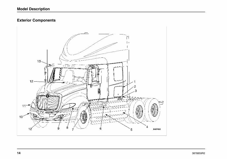
Exterior Components
14 3878859R2

Model Description
1. Luggage Door
2. External Hook-Ups for Telephone and TV
3. External Electrical Hook-Up (Shore Power)
4. Removable Skirt Option (Battery Access)
5. Chassis Skirt (Aero)
6. Fuel Cap
7. External Hook-Up for Block Heater
8. Side Marker/Turn Light
9. Fog Light
10. Tilt-Away Bumper
11. Headlight
12. VORAD (optional)
13. Sunshade
3878859R2 15

Model Description
16 3878859R2

Model Description
1. Work Lights
2. Luggage Door
3. Fuel Cap
4. VORAD (optional)
5. In-Transit Heat (optional)
6. Gladhand Storage Bracket
7. Grab Handle
3878859R2 17

Model Description
Cab Entry and Exit
WARNING
Do not step or climb upon any vehicle surfaceunless it is slip-resistant and a handhold isprovided. Failure to follow this warning couldcause you to slip or fall and could result inpersonal injury or death.
WARNING
A three-point stance should be used (three outof four extremities should be in contact withthe vehicle climbing system) at all times. Faceinward towards the cab when entering andexiting. Always keep steps and handholds incontinuous good repair. Make sure all attachingbolts and hardware are tight, thus eliminating anymovement of steps and handholds. Keep steps,grab handles and shoes free of grease, mud,dirt, fuel, ice and snow. Use extra care duringinclement weather. Failure to follow this warningcould cause you to slip or fall and could result inpersonal injury or death.
Hood
Raising the Hood
1. Hood
2. Hood Latch
3. Cowl
4. Hood Handle
5. Hood Restraining Shock
18 3878859R2

Model Description
WARNING
To prevent personal injury or death, never putany part of your body beneath a raised hoodunless the hood is all the way forward in its rangeof motion and is fully settled in the over centerposition.
CAUTION
To prevent damage to the windshield wipers,return them to their normal position beforeopening or closing hood.
CAUTION
Follow this procedure to prevent damage to thehood and/or painted surfaces.
NOTE: To avoid pinching, do not lift or lower the hood from theside.
1. Before opening the hood make sure that there is enoughroom in front of the vehicle for the hood to open completelywithout pinning or pinching yourself between the hood andany other structures.
2. Release the latches on both sides of the cowl.
3. With both feet firmly on the ground, grasp the hood handleand pull the hood forward over center and allow it to settleinto the raised position.
4. Make certain that the hood restraining shock is fullyextended before releasing hood.
Lowering the Hood
1. Make sure that the hood has no tools, parts, or people in itspath of motion.
2. Place both hands on the top edge of the grille and push thehood backward over center and allow it to settle into loweredposition.
3. Engage hood latches at both sides of cowl.
Tilt-Away Bumper
To avoid injury, a decal is attached to the top on each side of thebumper to identify the location not to place hands when raisingand lowering the tilt-away bumper.
3878859R2 19

Model Description
Lowering the Tilt-Away Bumper
1. Bumper Support Latch
2. Hood
3. Support Cables
4. Tilt-Away Bumper
1. Raise the hood to the fully upright position.
2. While standing on the driver-side of the Tilt-Away bumper,support the bumper with the left hand and release thebumper support latch with the right hand.
3. Walk around to the passenger-side of the Tilt-Away bumper.
4. Support the Tilt-Away bumper with the right hand andrelease the bumper support latch with the left hand.
5. Grasp and slowly lower the Tilt-Away bumper until it issupported by the support cables.
Raising the Tilt-Away Bumper
1. While standing on the passenger-side of the Tilt-Awaybumper, lift the bumper with the right hand and secure thebumper using the support latch with the left hand.
2. Walk to the driver-side of the Tilt-Away bumper.
3. Secure the Tilt-Away bumper using the support latch with theright hand.
4. Lower and latch the hood.
20 3878859R2

Model Description
Luggage Box Access
Driver and Passenger Side
NOTE: Driver and passenger luggage boxes open in the samemanner.
NOTE: Luggage box doors automatically lock when closed.Make sure you do not accidentally place and lock keys in theluggage box.
Open the luggage box door using the ignition/door key. The doorwill remain in a fully-opened position. To close the door, firmlypush the door down and to the locked position. The door willautomatically lock when shut.
Chassis Skirts
The optional chassis skirts on the International® ProStar®+Series trucks are available to provide improved aerodynamics.The rear driver side chassis skirt on sleeper models can beconveniently removed without tools to gain access to the batterybox.
Removal
1. Chassis Skirt
2. Keeper Bracket
3. Locking Handle in Unlock Position
3878859R2 21

Model Description
1. Locate the locking handle at the rear inside of thechassis skirt.
2. Release the locking handle from the keeper bracket.
3. Rotate the locking handle downward 90° to release thechassis skirt.
4. Grasp both ends of the chassis skirt and slide thechassis skirt upward, under the cab.
5. Allow the bottom of the chassis skirt to come outwardand remove the chassis skirt from the vehicle.
Installation
NOTE: There are two hooks on the back side of the chassis skirtthat must be fully engaged on the mounting bar to be securedproperly.
1. Grasp both ends of the chassis skirt, hold the bottomof the chassis skirt away from the vehicle, and slide thechassis skirt under the edge of the cab.
2. Lower the bottom of the chassis skirt onto the mountingbar and align the chassis skirt on the front chassis skirtand engage the two hooks.
3. Rotate the locking handle 90° upward to lock the chassisskirt in position.
4. Secure the locking handle in the keeper bracket.
NOTE: If vehicle is ordered with the optional No Idle Solution, therear passenger side chassis skirt that covers additional batterieswill remove and install the same as the rear driver side chassisskirt.
Extended Chassis Skirts
Optional extended chassis skirts are available for the ProStar®+Series trucks with sleeper and full aero package. While thepassenger’s side extended chassis skirt is stationary, the driver’sside opens to allow access to the deck ladder. To open, pull outon the upper right hand corner of the extended chassis skirt andopen to its full extension. To close, grab the upper right handcorner of the extended chassis skirt and guide it to its fully closedposition.
22 3878859R2
Inspection Guide
SECTION 3 — INSPECTION GUIDE
Introduction
General Information
WARNING
To prevent property damage, personal injury, ordeath when servicing the vehicle, park on a flatlevel service, set the parking brakes, turn theengine off, and chock the wheels.
WARNING
Exercise care when working on vehicles withrunning engines that are equipped with anautomatic fan clutch. The fan engages whenengine coolant reaches a predeterminedtemperature or the refrigerant pressure (ifequipped with air conditioning) reaches apredetermined setting. The fan will start withno advance warning. Failure to observe theseprecautions could result in vehicle damage,personal injury, or death.
WARNING
If vehicle is equipped with an automatictransmission, have a qualified technicianregularly check operation of transmission neutralstart switch. If unit starts in gear, the vehiclemay inadvertently move, which could result inproperty damage, personal injury, or death.
To be sure your vehicle is ready to operate, conduct a pre-tripinspection at the beginning of each work period. This sectiongives the operator suggested guidelines to be used in performingtractor and trailer pre-trip inspections. Safety is the mostimportant and obvious reason for doing a pre-trip inspection.Depending on the optional features of the vehicle being usedand any possible aftermarket items installed on the vehicle,these guidelines should be modified to include other necessaryinspection points. Follow the steps in this section and checkthem off to assure a proper vehicle inspection procedure. Thepages in this section may be reproduced locally and used on aregular basis.
If any component or system does not pass this inspection, itmust be corrected before operating the vehicle. Take your timegoing through the pre-trip inspection. Remember that a carefulpre-trip inspection saves time by eliminating unscheduled stopsto correct a faulty item.
Illustrations in this section identifies key locations of inspectionitems. The illustrations herein are typical and may not representall engine applications.
3878859R2 23

Inspection Guide
Tractor Inspection
Preparation
NOTE: Perform the following procedures prior to conducting thepre-trip inspection.
• Apply parking brakes.
• Turn on parking lights and hazard lights.
• Unhook the hood latches, raise the hood, unlatch and lowerthe tilt-away bumper.
• Check under the vehicle for oil, fuel, coolant leaks or othersigns of damage.
• Use pull cables or open drain cocks to allow air tanks to expelany existing water. Release pull cables or close drain cocks.
• Chock wheels on tractor and trailer, if attached.
• Start the engine and allow the air pressure to build up tonormal operating pressure of 115 to 130 psi (793 to 896kPa). Stop engine.
Exterior Lights Check
Perform an automatic check of all exterior lights by doing thefollowing steps:
1. Place the ignition key in the ON or ACC position, placethe transmission in neutral, and apply the parking brake.
2. Pressing the WORK LIGHT switch for approximately twoseconds before releasing will activate this feature.
3. The exterior light check will now cycle all vehicle lightsexcept the back-up light(s). The test flashes the exteriorlights on and off in three, two second cycles. The firsttwo second period illuminates park lights (clearance,identification, side marker and license plate lights),turn signal lights, low beam headlights, fog lights.The second two second period illuminates park lights(clearance, identification, side marker and license platelights), high beam headlights, brake lights, work lights.The third two second period turns off all lights. Thiscycle repeats until deactivated by the operator.
4. Walk around vehicle and inspect illumination of lights.
5. To cancel this feature, do one of the following: eitherpress the brake pedal, manually turn on any externallight, turn the key to OFF, or release the parking brake.The feature will automatically cancel approximately10 minutes after activation if not deactivated by theoperator.
6. Checking the backup lights requires two people andthe engine running. Depress the clutch (if applicable)and select reverse while the second person observesbackup light operation.
24 3878859R2

Inspection Guide
Left Side Cab Area
NOTE: If the vehicle is equipped with side skirts, it will benecessary to remove the left rear skirt to gain access to thebattery box.
Inspection Items
1. Cab Structure: Check body panels such as doors,fairings, air shield, sunshade, and cab extenders forsigns of breaks or damage. Check condition of cabmounting brackets and tilt hood latches.
2. Wipers: Check windshield wiper arms for proper springtension and wiper blades for damage.
3. Windshield: Check for damage to windshield and cleanif dirty.
4. Battery Box: Inspect for damage and secure mountingof battery box. Remove battery box cover.
5. Batteries and Cables: Check that batteries are securedand cases are not broken or leaking. Ensure cables arefree from damage. Tops of batteries and terminals mustbe clean and free from foreign material. Replace batterybox cover.
6. Fuel Tank(s): Check to see that the fuel tank(s) andcap(s) are secured and make sure there is no damageor leaks at the tank(s) or fuel lines.
3878859R2 25
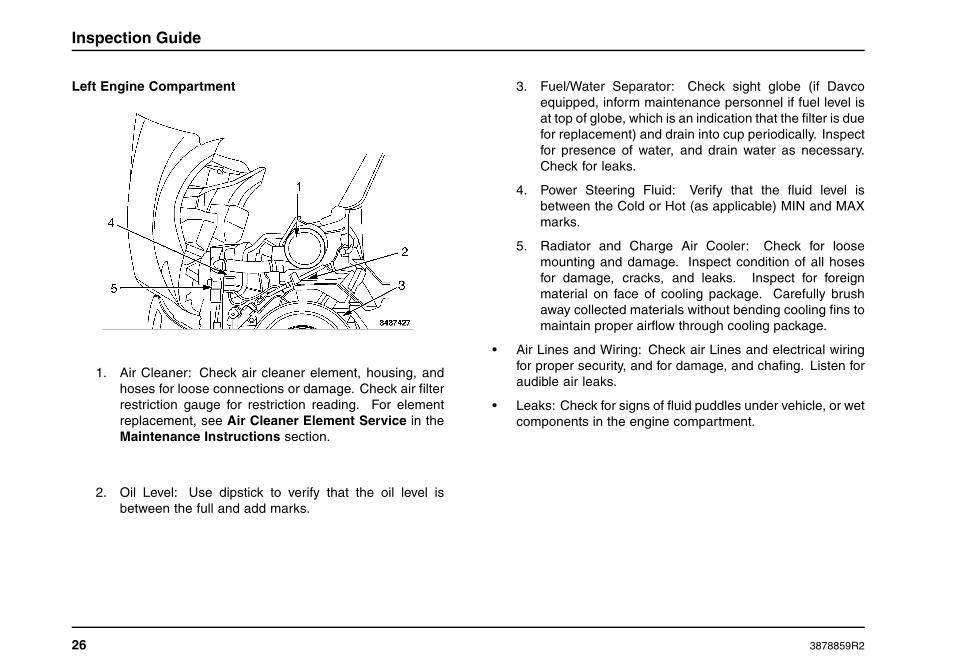
Inspection Guide
Left Engine Compartment
1. Air Cleaner: Check air cleaner element, housing, andhoses for loose connections or damage. Check air filterrestriction gauge for restriction reading. For elementreplacement, see Air Cleaner Element Service in theMaintenance Instructions section.
2. Oil Level: Use dipstick to verify that the oil level isbetween the full and add marks.
3. Fuel/Water Separator: Check sight globe (if Davcoequipped, inform maintenance personnel if fuel level isat top of globe, which is an indication that the filter is duefor replacement) and drain into cup periodically. Inspectfor presence of water, and drain water as necessary.Check for leaks.
4. Power Steering Fluid: Verify that the fluid level isbetween the Cold or Hot (as applicable) MIN and MAXmarks.
5. Radiator and Charge Air Cooler: Check for loosemounting and damage. Inspect condition of all hosesfor damage, cracks, and leaks. Inspect for foreignmaterial on face of cooling package. Carefully brushaway collected materials without bending cooling fins tomaintain proper airflow through cooling package.
• Air Lines and Wiring: Check air Lines and electrical wiringfor proper security, and for damage, and chafing. Listen foraudible air leaks.
• Leaks: Check for signs of fluid puddles under vehicle, or wetcomponents in the engine compartment.
26 3878859R2

Inspection Guide
Left Front of Tractor
WARNING
If wheels or tires must be changed, obtain experttire service help. Mounting and demountingof tires should only be performed by qualifiedpersonnel using necessary safety proceduresand equipment, otherwise the result could beproperty damage, personal injury, or death.
WARNING
Do not operate vehicle if any of the followingconditions are evident. Loss of steering orsuspension could cause loss of vehicle controland result in property damage, personal injury,or death.
NOTE: Retread tires are not recommended for use on steeringaxles of trucks.
1. Steering Linkage: Inspect connecting links, arms, rods,and steering intermediate shaft for worn, damaged,loose, or missing components.
2. Steering Gear: Look for missing or loose fasteners,power steering fluid leaks, and damage to powersteering hoses.
3. Frame: Check for cracks or bends in frame. Make surethere are no loose, cracked, bent, broken or missingcrossmembers or crossmember fasteners.
4. Spring Suspension: Check condition of spring forcracks, breaks, or shifting. Inspect spring hangerfasteners, shackles, U-bolts, and nuts for wear, damage,and tightness.
3878859R2 27

Inspection Guide
5. Shock Absorber: Check for cracks, leaks, and missingor broken mounting bolts or bushings.
6. Air Suspension (if equipped): Check for air leaks, loosecomponents, and damage to air bag. Inspect stabilizerbar for worn, loose, or damaged components.
7. Brake Chamber and Hoses: Check to see that the brakechambers are not cracked or damaged, and are securelymounted. Check for broken, loose or missing parts.Check for cracked, worn or frayed hoses, and for securecouplings.
8. Slack Adjuster: Check slack adjuster and chamber pushrod travel. When pulled by hand, push rod should notmove more than approximately one inch. Angle betweenpush rod and adjuster arm should be approximately 90degrees when brakes are applied.
9. Brake Lining and Drum: With brakes released, checkto see that brake linings (where visible) are notworn excessively thin [less than 1/4 inch (6mm)] orcontaminated by lubricant.
10. Wheel and Lug Nuts: Check for damaged or bent wheel.Check to see that all lug nuts are present and not loose(look for rust trails around nuts). Ensure that no cracksor damage are present at wheel mount holes.
11. Tire: Check tread depth, tire inflation and note if treadis evenly worn. Minimum tread depth is 4/32 inch onsteering tires. Look for cuts or other damage to the treador sidewalls. Check for missing, broken or damagedvalve cap and stem.
12. Hub: Check for obvious leaks on outside or inside ofwheel. Verify correct oil level in hub.
28 3878859R2
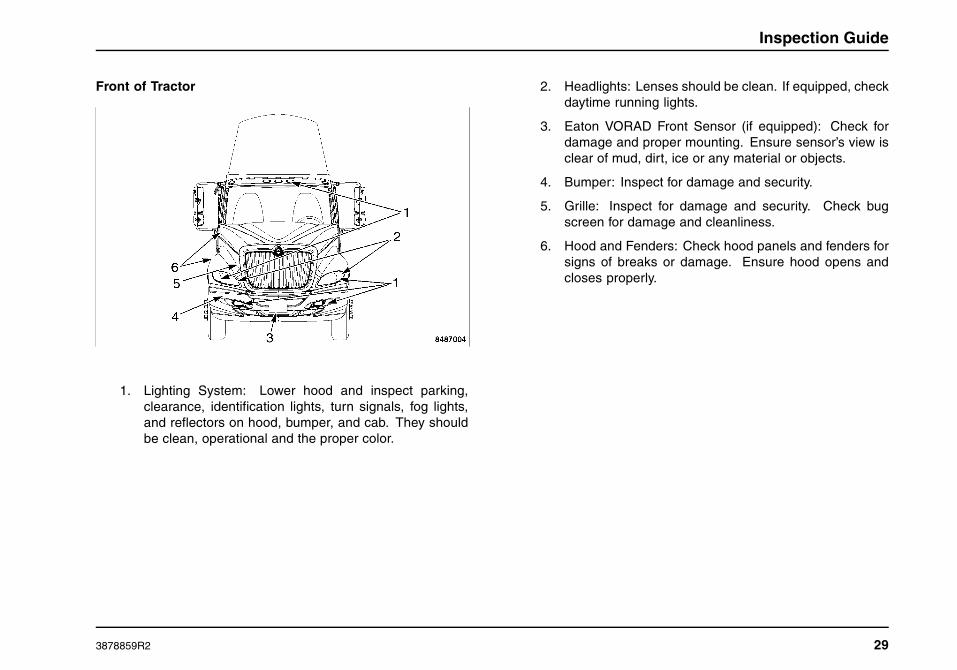
Inspection Guide
Front of Tractor
1. Lighting System: Lower hood and inspect parking,clearance, identification lights, turn signals, fog lights,and reflectors on hood, bumper, and cab. They shouldbe clean, operational and the proper color.
2. Headlights: Lenses should be clean. If equipped, checkdaytime running lights.
3. Eaton VORAD Front Sensor (if equipped): Check fordamage and proper mounting. Ensure sensor’s view isclear of mud, dirt, ice or any material or objects.
4. Bumper: Inspect for damage and security.
5. Grille: Inspect for damage and security. Check bugscreen for damage and cleanliness.
6. Hood and Fenders: Check hood panels and fenders forsigns of breaks or damage. Ensure hood opens andcloses properly.
3878859R2 29

Inspection Guide
Right Front of Tractor
WARNING
If wheels or tires must be changed, obtain experttire service help. Mounting and demountingof tires should only be performed by qualifiedpersonnel using necessary safety proceduresand equipment, otherwise the result could beproperty damage, personal injury, or death.
WARNING
Do not operate vehicle if any of the followingconditions are evident. Loss of steering orsuspension could cause loss of vehicle controland result in property damage, personal injury,or death.
NOTE: Retread tires are not recommended for use on steeringaxles of trucks.
1. Spring Suspension: Check condition of spring forcracks, breaks, or shifting. Inspect spring hangerfasteners, shackles, U-bolts, and nuts for wear, damage,and tightness.
2. Shock Absorber: Check for cracks, leaks, and missingor broken mounting bolts or bushings.
3. Air Suspension (if equipped): Check for air leaks, loosecomponents, and damage to air bag. Inspect stabilizerbar for worn, loose, or damaged components.
30 3878859R2
Inspection Guide
4. Wheel and Lug Nuts: Check for damaged or bent wheel.Check to see that all lug nuts are present and not loose(look for rust trails around nuts). Ensure that no cracksor damage are present at wheel mount holes.
5. Tire: Check tread depth, tire inflation and note if treadis evenly worn. Minimum tread depth is 4/32 inch onsteering tires. Look for cuts or other damage to the treador sidewalls. See if valve caps and stems are missing,broken or damaged.
6. Hub: Check for obvious leaks on outside or inside ofwheel. Verify correct oil level in hub.
7. Steering Linkage: Inspect connecting links, arms, androds for worn, damaged, loose, or missing components.
8. Brake Chamber and Hoses: Check to see that the brakechambers are not cracked or damaged, and are securelymounted. Check for broken, loose or missing parts.Check for cracked, worn or frayed hoses, and for securecouplings.
9. Slack Adjuster: Check slack adjuster and chamber pushrod travel. When pulled by hand, push rod should notmove more than approximately one inch. Angle betweenpush rod and adjuster arm should be approximately 90degrees when brakes are applied.
10. Brake Lining and Drum: With brakes released, checkto see that brake linings (where visible) are notworn excessively thin [less than 1/4 inch (6mm)] orcontaminated by lubricant.
11. Frame: Check for cracks or bends in frame. Make surethere are no loose, cracked, bent, broken or missingcrossmembers or crossmember fasteners.
3878859R2 31

Inspection Guide
Right Engine Compartment
WARNING
To prevent personal injury or death fromhot coolant or steam, use only the followingprocedure to remove the pressure cap from theradiator or expansion tank. Allow the engine tocool first. Wrap a thick, heavy cloth around thecap. Unscrew the cap slowly to allow pressureto release from under the cap. After the pressurehas been released, the pressure cap may beremoved.
1. Coolant Level: Do not remove pressure cap unlesscoolant is cool. Ensure fluid level is between theminimum and maximum fluid level range as marked onthe plastic translucent reservoir.
2. Radiator and Charge Air Cooler: Check for loosemounting and damage. Inspect condition of all hosesfor damage, cracks, and leaks. Inspect for foreignmaterial on face of cooling package. Carefully brushaway collected materials without bending cooling fins tomaintain proper airflow through cooling package.
3. Windshield Washer Fluid Level: Inspect the reservoirand verify that the fluid level is not empty and hasenough fluid to accomplish the upcoming mission. Ifadditional fluid is required, see Lubricant and SealerSpecifications chart, in the Maintenance Intervals andSpecifications section, for the correct fluid type beforefilling. Do not use water in freezing climates.
4. Drive Belts: Inspect all belts for frays, cracks, loosefibers, or visible signs of wear. With engine off, presson all belts to test for proper belt tensioner performance
5. Cowl Vent: Ensure air inlet cover is free of dirt anddebris.
• Air Lines and Wiring: Check air Lines and electrical wiringfor proper security, damage, and chafing. Listen for audibleair leaks.
32 3878859R2

Inspection Guide
• Leaks: Check for signs of fluid puddles under vehicle, or wetcomponents in the engine compartment.
Right Side of Cab
WARNING
Maintain adequate clearance between all parts ofthe exhaust system and all hoses, wires and linesfor engine cooling, brake system, fuel system,power steering system and electrical system.Heat damage to hoses, wires may cause vehiclemalfunction that could result in property damage,personal injury, or death.
1. Cab Structure: Check body panels such as doors,fairings, air shield, and cab extenders for signs ofbreaks or damage. Check condition of cab mountingbrackets and tilt hood latches.
2. Fuel Tank: Check to see that the fuel tank and cap aresecured and make sure there is no damage or leaks atthe tank or fuel lines.
3. Eaton VORAD sensor (if equipped): Check for damageand proper mounting. Ensure sensor’s view is clear ofmud, dirt, ice or any material or objects.
3878859R2 33

Inspection Guide
Right Side Under Vehicle
WARNING
Maintain adequate clearance between all parts ofthe exhaust system and all hoses, wires and linesfor engine cooling, brake system, fuel system,power steering system and electrical system.Heat damage to hoses, wires or lines may causevehicle malfunction that could result in propertydamage, personal injury, or death.
1. Drive Shaft: Ensure that all shaft couplings are secure.
2. Exhaust System: Check to see that all component partsare securely mounted and no cracks, holes, or severedents are visible. Evidence of soot build up aroundclamps or connections is a clear indicator of a leakbeing present. Ensure that all hoses, wires, and airlines are secured away from exhaust components.
3. Transmission: Inspect for leaks.
4. Frame: Check for cracks or bends in frame. Make surethere are no loose, cracked, bent, broken or missingcrossmembers or crossmember fasteners.
• Air Lines and Wiring: Check air Lines and electrical wiringfor proper security, damage, and chafing. Listen for audibleair leaks.
34 3878859R2
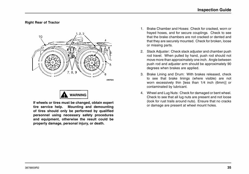
Inspection Guide
Right Rear of Tractor
WARNING
If wheels or tires must be changed, obtain experttire service help. Mounting and demountingof tires should only be performed by qualifiedpersonnel using necessary safety proceduresand equipment, otherwise the result could beproperty damage, personal injury, or death.
1. Brake Chamber and Hoses: Check for cracked, worn orfrayed hoses, and for secure couplings. Check to seethat the brake chambers are not cracked or dented andthat they are securely mounted. Check for broken, looseor missing parts.
2. Slack Adjuster: Check slack adjuster and chamber pushrod travel. When pulled by hand, push rod should notmove more than approximately one inch. Angle betweenpush rod and adjuster arm should be approximately 90degrees when brakes are applied.
3. Brake Lining and Drum: With brakes released, checkto see that brake linings (where visible) are notworn excessively thin [less than 1/4 inch (6mm)] orcontaminated by lubricant.
4. Wheel and Lug Nuts: Check for damaged or bent wheel.Check to see that all lug nuts are present and not loose(look for rust trails around nuts). Ensure that no cracksor damage are present at wheel mount holes.
3878859R2 35

Inspection Guide
5. Tires: Check tread depth, tire inflation and note if treadis evenly worn. Minimum tread depth is 2/32 inch on alldrive tires. Look for cuts or other damage to the treadsidewalls. See if valve caps and stems are missing,broken or damaged. Check dual spacing to ensure thatdual wheels are evenly separated, and that tires are nottouching one another.
6. Hub: Check for obvious leaking on outside or inside ofwheel. Inspect axle flanges and wheel seals for leaksand loose mounting hardware or broken items. Checklube level, if equipped with sight glass.
7. Spring Suspension: Check condition of spring forcracks, breaks, or shifting. Inspect spring hangerfasteners, shackles, U-bolts, and nuts for wear, damage,and tightness.
8. Torque Rods and Shock Absorbers: Check to see thattorque rods are not cracked, broken or missing. Checkshock absorbers for cracks or leaks. There should beno missing or broken mounting bolts or worn bushings.
9. Air Suspension (if equipped): Check for air leaks, loosecomponents, and damage to air bag. Inspect ride heightvalve and linkage for damage.
10. Frame: Check for cracks or bends in frame. Make surethere are no loose, cracked, bent, broken or missingcrossmembers or crossmember fasteners.
• Air Lines and Wiring: Check air lines and electrical wiring forproper security, damage, and chafing. Listen for audible airleaks.
36 3878859R2

Inspection Guide
Rear of Tractor 1. Lights and Reflectors: Check to see that reflectors andlights are clean. Make sure none are missing or broken.Rear running lights should be clean, not broken and redin color.
2. Frame: Check for cracks or bends in frame. Make surethere are no loose, cracked, bent, broken or missingcrossmembers or crossmember fasteners.
3. Mud flaps: Inspect rear mud flaps and mountings fordamage and proper security.
• Air Lines and Wiring: Check air Lines and electrical wiringfor proper security, and for damage, and chafing. Listen foraudible air leaks.
3878859R2 37

Inspection Guide
Left Rear of Tractor
WARNING
If wheels or tires must be changed, obtain experttire service help. Mounting and demountingof tires should only be performed by qualifiedpersonnel using necessary safety proceduresand equipment, otherwise the result could beproperty damage, personal injury, or death.
1. Brake Chamber and Hoses: Check for cracked, worn orfrayed hoses, and for secure couplings. Check to seethat the brake chambers are not cracked or dented andthat they are securely mounted. Check for broken, looseor missing parts.
2. Slack Adjuster: Check slack adjuster and chamber pushrod travel. When pulled by hand, push rod should notmove more than approximately one inch. Angle betweenpush rod and adjuster arm should be approximately 90degrees when brakes are applied.
3. Brake Lining and Drum: With brakes released, checkto see that brake linings (where visible) are notworn excessively thin [less than 1/4 inch (6mm)] orcontaminated by lubricant.
4. Frame: Check for cracks or bends in frame. Make surethere are no loose, cracked, bent, broken or missingcrossmembers or crossmember fasteners.
38 3878859R2

Inspection Guide
5. Wheel and Lug Nuts: Check for damaged or bent wheel.Check to see that all lug nuts are present and not loose(look for rust trails around nuts). Ensure that no cracksor damage are present at wheel mount holes.
6. Tires: Check tread depth, tire inflation and note if treadis evenly worn. Minimum tread depth is 2/32 inch on alldrive tires. Look for cuts or other damage to the treadand sidewalls. See if valve caps and stems are missing,broken or damaged. Check dual spacing to ensure thatdual wheels are evenly separated, and that tires are nottouching one another.
7. Hub: Check for obvious leaking on outside or inside ofwheel. Inspect axle flanges and wheel seals for leaksand loose mounting hardware or broken items. Checklube level, if equipped with sight glass.
8. Spring Suspension: Check condition of spring forcracks, breaks, or shifting. Inspect spring hangerfasteners, shackles, U-bolts, and nuts for wear, damage,and tightness.
9. Torque Rods and Shock Absorbers: Check to see thattorque rods are not cracked, broken or missing. Checkshock absorbers for cracks or leaks. There should beno missing or broken mounting bolts or worn bushings.
10. Air Suspension (if equipped): Check for air leaks, loosecomponents, and damage to air bag. Inspect ride heightvalve and linkage for damage.
• Air Lines and Wiring: Check air Lines and electrical wiringfor proper security, damage, and chafing. Listen for audibleair leaks.
3878859R2 39

Inspection Guide
Fifth Wheel and Coupling Area
1. Sliding 5th Wheel (if equipped): Check for loose ormissing pins in the slide mechanism. If air powered,check for air leaks. Make sure that 5th wheel is not sofar forward that tractor frame or mud flaps will striketrailer landing gear during turns.
2. Lubrication: Make sure that top surface (face) of the 5thwheel has a coat of grease.
3. Mounting Bolts and Release Handle: Look for looseor missing mounting brackets, clamps, bolts or nuts.All locking pins must be in place and free of damage.Ensure that release handle is in the engaged positionand the safety latch is functioning and free of damage.
4. Deck Plate and Access Steps: Check to ensure that thedeck plate and steps are clean, securely bolted in place,and clear of loose objects.
5. Trailer Coupling Cords: Inspect air lines and electricalcord for cuts, chafing, damage, and proper security.Check air lines for audible air leaks.
6. Work Light(s): Check operation, and clean as needed.
40 3878859R2
Inspection Guide
Cab Interior Inspection
1. Safety/Emergency Equipment: Prior to enteringcab, verify that vehicle is equipped with the properequipment. Walk around vehicle and check that allsteps and grab handles, inside and out, as well asbehind, are tight and clean. Use extreme caution andmaintain 3 point contact at all times.
2. Doors: Check door latches for positive closing, latchingand locking.
3. Clutch/Gearshift: Depress clutch pedal (if present) andverify transmission is in neutral before turning on starter;keep depressed until engine reaches idling speed andvehicle in neutral.
4. Oil Pressure Builds: Check to see that oil pressure isbuilding to a normal level. Engine oil pressure gaugeshould begin a gradual rise to normal operating range.
5. Low Air Alarm: The low air pressure alarm may soundimmediately after the engine starts but before the aircompressor has built up minimum 55 psi (379 kPa)pressure. The low air pressure alarm should stop whenthe air pressure reaches 60 to 76 psi (414 to 524 kPa).Let the air pressure build to governor cut-out pressure,which should occur between 115 and 130 psi (793 and896 kPa).
6. Accelerator: Depress accelerator pedal and verify that itoperates smoothly without any binding or irregular feel.Remove foot from accelerator and make sure enginereturns to idle immediately.
7. Voltmeter: Check the gauge to see if the alternator ischarging between 12.5 and 14.5 volts.
8. Steering Play: Check for smooth operation. Checkfor excessive looseness in the steering linkages. Thesteering wheel should have less than 10 degrees freeplay (approximately 2 inches at rim of 18 inch steeringwheel).
9. Seats: Be sure seats are firmly engaged to avoidforward or rearward movement when starting orstopping. Make sure that seats and tether strapsare free from damage and secured to floor.
10. Horn(s): Check to see that horn(s) operate properly.
11. Mirrors: Check mirrors for proper adjustment, damage,cleanliness, and proper mounting. Check (optional)power mirrors and (optional) heated mirrors for properoperation.
12. Doors: Ensure windows are clean and operate properlyand smoothly in both doors.
13. Windshield and Wipers: Check windshield for cracks,dirt, illegal stickers or other obstructions to view. Ensurewipers and windshield washer are functioning properly.
14. Lighting Indicators: Check to see that dash indicatorsilluminate when corresponding lights are turned on.
15. Heater/Defroster: Check to be sure that heater/defrosteris working. Verify adequate air flow from louvers andvents. Operate Temperature and Mode controls to verifyproper operation.
3878859R2 41

Inspection Guide
16. Air Brake Check: Check the air brakes in the followingmanner:
a. Chock wheels if necessary. Push in parkingbrake and start engine.
b. Check for air compressor or governor cut-out pressure at 125 to 135 psi (862 to 931kPa). Shift into a low gear, and gentlypull against service and parking brakesseparately to make sure they hold.
c. Shut off engine and TURN KEY BACK ON.
d. Without brake pedal applied, note airpressure drop for one minute. It shouldbe less than 2 psi (14 kPa).
e. Depress and hold brake pedal and makesure there is no more than a 3 psi (21 kPa)per minute pressure drop. For combinationvehicles, there should be no more than 4 psi(28 kPa) per minute pressure drop.
f. Step on and off brake pedal and check thatwarning indicator and alarm come on atabout 60 or 76 psi (414 or 524 kPa).
g. Step on and off brake pedal and check tomake sure the parking brake knobs pop outbetween 20 and 45 psi (138 and 310 kPa).
42 3878859R2

Controls/Features
SECTION 4 — CONTROLS/FEATURES
Introduction
General Information
The controls/features enable the driver to monitor and managethe operation of the majority of the vehicle’s functions. Thissection describes and identifies various components within theOverhead Console, Instrument Panel Gauge Cluster, CenterDash Panel/Wing Panel, Steering Column and Switches,Steering Wheel Controls, Door and Window Controls, EatonVORAD Collision Warning System, and Vehicle InformationDisplay.
Electrical
WARNING
This vehicle may be equipped from the factorywith electrical switches intended to operateequipment that was installed by a truckequipment manufacturer (TEM). Instructions,Cautions, and Warnings for this additionalequipment will NOT be found in this manual.Read and understand the appropriate manualfor the specific equipment in question beforeoperating. Failure to observe this warning maycause property damage, personal injury, or death.
NOTE: This vehicle may be equipped with electronic, applicationspecific options not described in this Operator’s Manual. Manyof these features are supplied with rocker switches that havecustom labels applied. The presence of these options as factoryinstalled can be verified from the Line Set Ticket included withthe vehicle. A truck equipment manufacturer (TEM), however,may have installed some of these options after production. Inthat case, they will not appear on the Line Set Ticket. If installedby a TEM, you should receive an operating guide and/or trainingfor the specific functions provided. Familiarize yourself with all ofthe switches that control chassis, engine, and body equipmentand seek adequate training on the function of all features beforeoperating this vehicle.
Electrical System
The Electrical System provides a means to distribute theelectrical power and provide the driver with controls andindications of vehicle performance. Unlike previous electricalsystems, this system uses multiplexing for connecting to majorfunctional areas of the truck with much less wiring. The systemis controlled by the Body Controller, which provides interfaces toa majority of vehicle switches and sensors. The Body Controlleralso communicates with the standard and optional systemcontrollers and modules in the vehicle.
3878859R2 43

Controls/Features
Dash Components
1. Instrument Panel Gauge Cluster
2. Center Dash Panel/Wing Panel
3. Fuse Panel Cover
4. Control Switches
5. Transmission Gear Switch with Hi/Lo Range Switch andOptional Hi/Lo Splitter Switch
6. Tilt/Telescoping Steering Column
7. Push Button Gear Selector for Optional AutomatedManual Transmission.
8. City Horn Pad
9. Ignition Switch
10. Vehicle Information Display (optional)
44 3878859R2
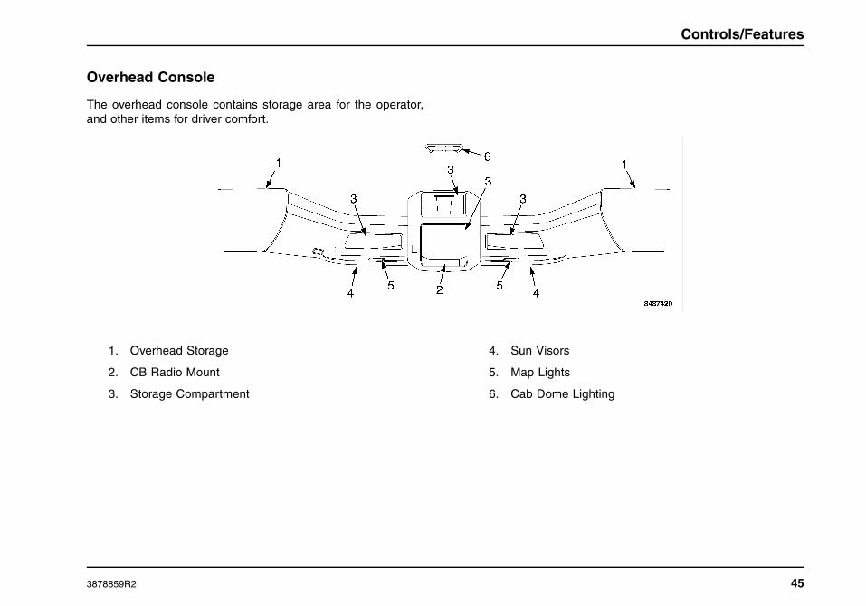
Controls/Features
Overhead Console
The overhead console contains storage area for the operator,and other items for driver comfort.
1. Overhead Storage
2. CB Radio Mount
3. Storage Compartment
4. Sun Visors
5. Map Lights
6. Cab Dome Lighting
3878859R2 45
Controls/Features
Instrument Panel Gauge Cluster
The instrument panel gauge cluster includes the instrumentgauges, warning indicators, and an Integral Digital Display, thatprovide odometer, transmission gear indication, and compass
heading and outside temperature displays. This instrumentpanel gauge cluster displays the crucial operational functionsof the vehicle. The following are descriptions and illustrationsof the gauges, warning indicators, and integral digital displayoptions.
46 3878859R2

Controls/Features
3878859R2 47

Controls/Features
Warning Indicators
The instrument panel gauge cluster contains 25 individual LEDwarning indicators. These indicators are used to monitor vehicleoperation and indicate a WARNING or STOP condition. Thesewarning indicators are driven by the software in the instrumentpanel gauge cluster. At ignition, the warning indicators willilluminate for 8 to 10 seconds, as part of the vehicle power-upsequence.
ItemNo.
Item Description
1 Illuminates Yellow when the intakeheaters and glow plugs are in operationand special starting procedures arerequired. Refer to the Starting Switchparagraph in the Vehicle Operationsection for more information.
2 Illuminates Yellow to alert driver thatvehicle idle shutdown timer will turnengine off in 30 seconds.
3 Illuminates Yellow. Used in conjunctionwith other Warning Indicators or GeneralText and Warning Messages and maybe accompanied by an audible alarmto indicate an Alert condition to theoperator.
4 Illuminates Yellow. Used in conjunctionwith other Warning Indicators or GeneralText and Warning Messages to indicatean Alert condition to the operator.
5 Illuminates Red Used in conjunction withother Warning Indicators or General Textand Warning Messages to indicate a redSTOP alert.
6 Not Used.
7 Illuminates Red when the parking brakeis applied. If the brake warning indicatordoes not illuminate, or if it stays on withthe parking brake not engaged, seekservice immediately.
8 Illuminates Green to assist operatorsin determining when it is appropriate toshift the transmission to a higher gear inorder to maximize driving fuel economy.
9 Illuminates Yellow to indicate enginebrake capability has been activated.
10 Illuminates Yellow when a trailer antilockbrake system malfunction has beendetected. If the ABS indicator staysilluminated or continues to flash, havethe system serviced immediately.
48 3878859R2

Controls/Features
11 Illuminates Yellow when the tractioncontrol system is turned off. It alsoilluminates momentarily when thetraction control system is on and islimiting wheel spin. Indicator blinks ifslippery road conditions exist. If thishappens, adjust your driving accordingly.Refer to the Operation section for moreinformation.
12 Not used.
13 Illuminates Yellow when exhaust systemcomponents are operating under normalconditions and exhaust gases are atextremely high temperatures.
14 Diesel Particulate Filter (DPF) statusindicator Illuminates Yellow (Solidor Flashing) to indicate the need toregenerate the Diesel Particulate Filter.(See Exhaust Regen in the VehicleOperation Section).
15 Engine Emissions Control SystemMalfunction Indicator Lamp (MIL)
Illuminates Yellow when an emissionsproblem has occurred.
16 Illuminates Red when a parking brakesystem malfunction has been detected.If the Service Parking Brake indicatorstays illuminated, have the systemserviced immediately.
17 Optional indicator illuminates Redimmediately after ignition is turned on toremind operator to fasten seat belt.
Optional Seat Belt Reminder with SeatBelt Monitoring causes initial visualindication, then flashes with audiblealarm when ignition is on, parking brakeis released, and seat belt is not fastened.
18 Not used.
19 Not used.
20 Illuminates Yellow when the PTOfunction (if installed) is activated.
21 Illuminates Yellow when an antilockbrake system malfunction has beendetected. If the ABS indicator staysilluminated or continues to flash, havethe system serviced immediately.
22 Not used.
23 Flashes Green when the left turn signalor the hazard lights are turned on.
3878859R2 49

Controls/Features
24 Illuminates Blue when the high beamhead lamps are turned on.
25 Flashes Green when the right turn signalor the hazard lights are turned on.
NOTE: If the MIL is illuminated, it is the vehicle owner’sresponsibility to have the engine repaired or face fines.
Gauges
There are 10 gauges in the instrument panel gauge cluster tohelp monitor the vehicle while in service. Most gauges havein-gauge warning indicators which turn on if the gauge pointermoves into an out-of-acceptable-range condition. When theignition switch is turned on, the gauge indicators will be on. Ifany indicator fails to go out after starting engine, stop engine anddetermine cause of the gauge indication that is out of acceptablerange. Metric versions of the gauges and speedometer areavailable as an option.
26 Indicates the transmission lubricanttemperature in degrees Fahrenheit (°F)(optional).
27 Indicates the engine lubricanttemperature in degrees Fahrenheit(°F) (optional).
28 Indicates engine coolant temperature indegrees Fahrenheit (°F).
29 Indicates engine oil pressure in poundsper square inch (PSI).
30 The tachometer indicates engine speed(RPM). The engine can be operatedbetween idle speed and high idle speedwithout damage but should not beallowed to over-speed (such as whengoing downhill).
31 The speedometer indicates the vehiclespeed in miles per hour (MPH) andkilometers per hour (Km/h).
32 Indicates the approximate fuel level inthe fuel tanks.
50 3878859R2

Controls/Features
33 Indicates the battery voltage (VOLTS)when the ignition switch is in the ONposition.
34 Provides indication of air pressureavailable for the primary air brakes inpounds per square inch (PSI).
35 Provides indication of air pressureavailable for the secondary air brakes inpounds per square inch (PSI).
3878859R2 51
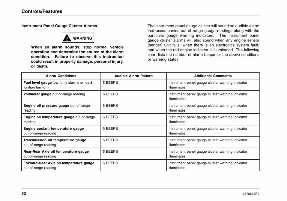
Controls/Features
Instrument Panel Gauge Cluster Alarms
WARNING
When an alarm sounds, stop normal vehicleoperation and determine the source of the alarmcondition. Failure to observe this instructioncould result in property damage, personal injury,or death.
The instrument panel gauge cluster will sound an audible alarmthat accompanies out of range gauge readings along with theparticular gauge warning indicators. The instrument panelgauge cluster alarms will also sound when any engine sensor(sender) unit fails; when there is an electronics system fault;and when the red engine indicator is illuminated. The followingchart lists the number of alarm beeps for the above conditionsor warning states:
Alarm Conditions Audible Alarm Pattern Additional Comments
Fuel level gauge low (only alarms on eachignition turn-on)
5 BEEPS Instrument panel gauge cluster warning indicatorilluminates.
Voltmeter gauge out-of-range reading 5 BEEPS Instrument panel gauge cluster warning indicatorilluminates.
Engine oil pressure gauge out-of-rangereading
5 BEEPS Instrument panel gauge cluster warning indicatorilluminates.
Engine oil temperature gauge out-of-rangereading
5 BEEPS Instrument panel gauge cluster warning indicatorilluminates.
Engine coolant temperature gaugeout-of-range reading
5 BEEPS Instrument panel gauge cluster warning indicatorilluminates.
Transmission oil temperature gaugeout-of-range reading
5 BEEPS Instrument panel gauge cluster warning indicatorilluminates.
Rear-Rear Axle oil temperature gaugeout-of-range reading
5 BEEPS Instrument panel gauge cluster warning indicatorilluminates.
Forward-Rear Axle oil temperature gaugeout-of-range reading
5 BEEPS Instrument panel gauge cluster warning indicatorilluminates.
52 3878859R2
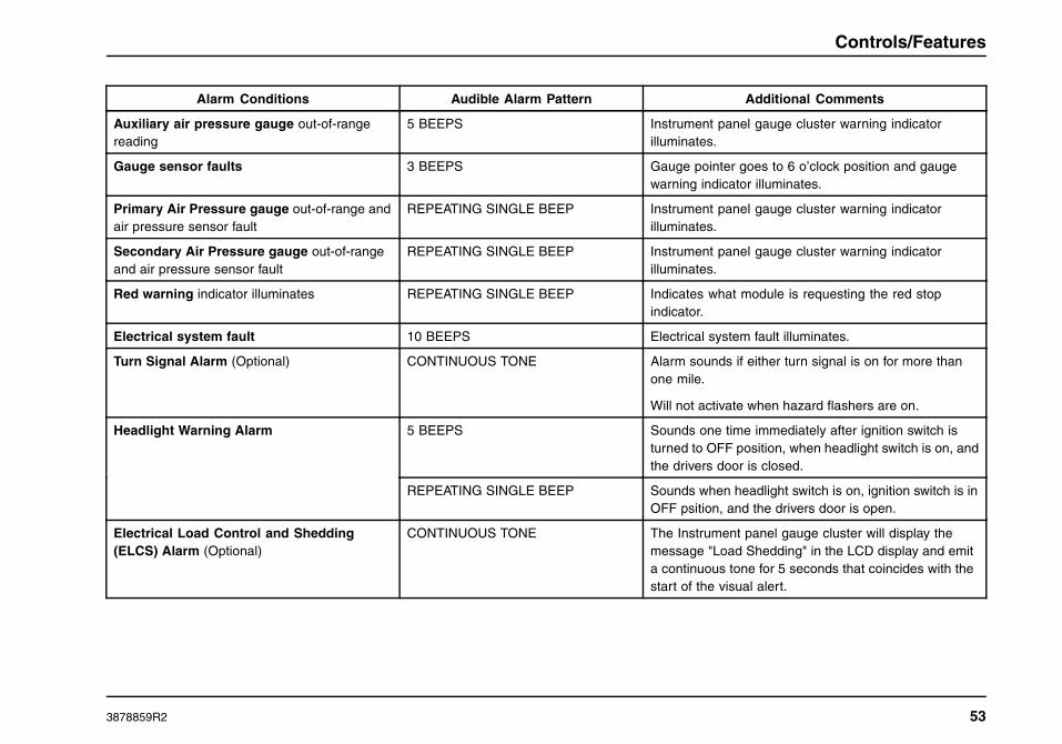
Controls/Features
Alarm Conditions Audible Alarm Pattern Additional Comments
Auxiliary air pressure gauge out-of-rangereading
5 BEEPS Instrument panel gauge cluster warning indicatorilluminates.
Gauge sensor faults 3 BEEPS Gauge pointer goes to 6 o’clock position and gaugewarning indicator illuminates.
Primary Air Pressure gauge out-of-range andair pressure sensor fault
REPEATING SINGLE BEEP Instrument panel gauge cluster warning indicatorilluminates.
Secondary Air Pressure gauge out-of-rangeand air pressure sensor fault
REPEATING SINGLE BEEP Instrument panel gauge cluster warning indicatorilluminates.
Red warning indicator illuminates REPEATING SINGLE BEEP Indicates what module is requesting the red stopindicator.
Electrical system fault 10 BEEPS Electrical system fault illuminates.
Turn Signal Alarm (Optional) CONTINUOUS TONE Alarm sounds if either turn signal is on for more thanone mile.
Will not activate when hazard flashers are on.
5 BEEPS Sounds one time immediately after ignition switch isturned to OFF position, when headlight switch is on, andthe drivers door is closed.
Headlight Warning Alarm
REPEATING SINGLE BEEP Sounds when headlight switch is on, ignition switch is inOFF psition, and the drivers door is open.
Electrical Load Control and Shedding(ELCS) Alarm (Optional)
CONTINUOUS TONE The Instrument panel gauge cluster will display themessage "Load Shedding" in the LCD display and emita continuous tone for 5 seconds that coincides with thestart of the visual alert.
3878859R2 53

Controls/Features
Direct Drive Warning Indicators
The direct drive warning indicators give information to theoperator of various conditions of the vehicle. Eight spaces areavailable for the direct drive warning indicators. Blank coverplates will be used in spaces that do not have direct drivewarning indicator installed at those locations.
ItemNo.
Item Color Description
36 Yellow Forward rear axledifferential is locked.
37 Yellow Rear axle differential islocked.
38 BLANK Not used
39 Yellow ICON system is activated.
40 BLANK Not used
41 BLANK Not used
ItemNo.
Item Color Description
42 Yellow Luggage door is ajar.
43 Yellow Engine brake capability isactivated.
Integral Digital Display
The Integral Digital Display is located below the speedometerand the tachometer. It is arranged in four quadrants that displayvehicle information. The four quadrants can be individuallyselected by using the display control button.
Display Control. The Display control is used to scroll to aquadrant and to select the various modes within a quadrant. Tonavigate between quadrants, turn and release the control eitherclockwise or counterclockwise. To select the screens within aquadrant, press and release the control. Pressing and holdingthe control for more than 3 seconds to reset the value of theselected quadrant parameter (if the parameter can be reset).The selected quadrant is identified by a vertical bar located inthe far right of quadrant. In quadrant 1, the odometer screencan be toggled between English and Metric, by pressing andholding the control.
Item No. Quadrant Number and Message Function Message Description
44 Quadrant 4: Transmission Gear Indication Transmission gears for the Allison P-R-N-D-L gear selection display, or theEaton Transmission display.
54 3878859R2

Controls/Features
Item No. Quadrant Number and Message Function Message Description
45 Quadrant 1: Informational Messages Informational Display Screens:
• Odometer
• Trip Odometer
• Total Engine Hours
• Trip Hours
• Machine PTO A or B Hours
• Machine Trip PTO A or B Hours
• Engine PTO Hours
• Engine PTO Trip Hours
• Instantaneous Fuel Economy
• Trip Average Fuel Economy
• Machine PTO Fuel Used A or B
• Machine PTO Trip Fuel Used A or B
• Engine PTO Fuel Used
• Engine PTO Trip Fuel Used
• Trip Idle Fuel Used
• Axle Load Indication (Front and/or Rear)
• Diesel Particulate Filter Level
46 Quadrant 2: General Text and WarningMessages
Displays a variety of messages ranging in priority necessary for vehiclemonitoring and operation, and vehicle malfunction warnings. Some messagesare used in conjunction with instrument panel gauge cluster warning indicators(see list of messages in the Integral Digital Display section in Vehicle Operations)
3878859R2 55

Controls/Features
Item No. Quadrant Number and Message Function Message Description
47 Quadrant 3: Compass Heading/OutsideTemperature
(Optional) Displays compass heading when vehicle is equipped with a compassmodule.
Displays outside temperature (reading is obtained from the temperature sensor).
48 Display Control Toggles the information display from one screen to the next when pressed andreleased.
General Text and Warning Messages
The operator of the vehicle can makeadjustments to the sleeper temperatureand/or sleeper blower speeds by usingthe SLPR TEMP and/or SLPR FAN dashswitches that are located on the center dashpanel/wing panel. When the operator makesa change with either of these two switchesthe appropriate graphic for the sleeper temperature or sleeperblower speeds will be displayed in the general text and warningmessage area of the instrument panel gauge cluster.
TemperatureGraphic
Blower SpeedGraphic
56 3878859R2

Controls/Features
Optional Instrument panel gauge cluster CompassCalibration Procedure
All new vehicles with an optional compass must have an initialcompass calibration performed. A compass calibration may ormay not have been completed at the vehicle assembly plant.If the compass headings are noticeably incorrect, or becomenoticeably incorrect, or the NO CAL message is displayed, theDeclination Zone may need to be reset to agree with the currentgeographic location, or the Compass Directional Calibration willneed to be recalibrated.
The compass direction is displayed in the lower left quadrantof the instrument panel gauge cluster display just below theoutdoor temperature reading. Text messages necessary tocalibrate the compass can be found in the instrument panelgauge cluster display in the lower right quadrant (quadrant 2)of the display. Twist the instrument panel gauge cluster displayknob until the cursor is flashing in the lower right quadrant.Press the instrument panel gauge cluster display knob untilthe desired text message is displayed. Compass Calibrationrelated text messages include “Calibrate Compass”, “CompassDeclination”, “Declination Zone #”, and “End Calibration”.
NOTE: The Declination Zone for the location where the CompassCalibration procedure is being performed must be set first, andthereafter the Compass Directional Calibration procedure can beperformed. Both procedures are listed on the following pagesand must be followed exactly to ensure proper calibration of thecompass.
Compass Declination Zone Set Procedure
The Declination Zone number is used to account for theerrors between magnetic North and true North in the vehicle’sgeographic operating area, and must be set correctly for thecompass to display accurate headings.
NOTE: When calibrating/recalibrating the compass, you mustselect the Declination Zone which corresponds to the geographiclocation where the compass calibration is being performed. Itcan be reset later to match the Declination zone where thevehicle will be operating.
For vehicles that regularly operate coast-to-coast or in severaldifferent Declination Zones, either choose a Declination Zone inthe geographic center of the vehicle’s operating area, or changethe Declination Zone daily to match the present DeclinationZone.
To begin the Declination Zone set procedure, the vehicle must bestopped with ignition key ON. Refer to Zone Map for determiningthe proper Declination Zone number.
3878859R2 57
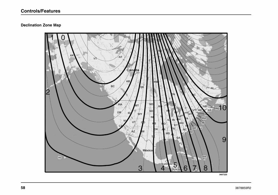
Controls/Features
Declination Zone Map
58 3878859R2

Controls/Features
Step Procedure Displayed Message
1
Select Quadrant 2 (lower right) on the display by turning the display control knob eitherclockwise or counterclockwise.
2
Select the Compass Declination message by pressing and releasing the display controlknob until this message appears.
3
Press and hold the display control knob until any Declination Zone number (0 – 10) isdisplayed.
4
Turn the display control knob clockwise or counterclockwise until the desired DeclinationZone number is displayed. Refer to Declination Zone Map to determine the propernumber for the current geographic location.
NOTE: If no Declination Zone number is selected within 15 seconds, the display will returnto the Compass Declination message.
NOTE: If the compass is being calibrated/recalibrated the Declination Zone must be setto the Zone number for the location where the compass calibration/recalibration is beingperformed regardless of the location where the vehicle will eventually operate.
5
Press and HOLD the display control knob until the Compass Declination messageappears (this indicates that the new Declination Zone number has been programmedinto the compass).
3878859R2 59
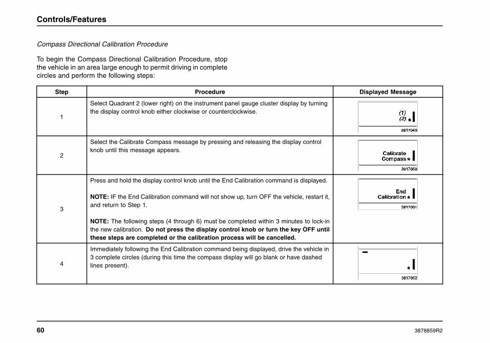
Controls/Features
Compass Directional Calibration Procedure
To begin the Compass Directional Calibration Procedure, stopthe vehicle in an area large enough to permit driving in completecircles and perform the following steps:
Step Procedure Displayed Message
1
Select Quadrant 2 (lower right) on the instrument panel gauge cluster display by turningthe display control knob either clockwise or counterclockwise.
2
Select the Calibrate Compass message by pressing and releasing the display controlknob until this message appears.
3
Press and hold the display control knob until the End Calibration command is displayed.
NOTE: IF the End Calibration command will not show up, turn OFF the vehicle, restart it,and return to Step 1.
NOTE: The following steps (4 through 6) must be completed within 3 minutes to lock-inthe new calibration. Do not press the display control knob or turn the key OFF untilthese steps are completed or the calibration process will be cancelled.
4
Immediately following the End Calibration command being displayed, drive the vehicle in3 complete circles (during this time the compass display will go blank or have dashedlines present).
60 3878859R2

Controls/Features
5
Stop the vehicle and wait shortly. The End Calibration message should reappear onthe display.
6
Push and HOLD the display control knob until the End Calibration command disappears.The calibration should now be complete. IMPORTANT!: Just pressing and failingto hold the display control knob inward until the End Calibration commanddisappears will cancel the calibration procedure and you must start over at Step 1.
7
Test the compass calibration. Turn the vehicle ignition key OFF and then restart thevehicle. Wait 10 seconds to for the compass to complete its self test. Drive the vehiclein a circle and note the compass readings. If the lower left quadrant of the InstrumentPanel Gauge Cluster Display shows the correct compass/vehicle heading, the compasscalibration is now complete. If the compass readings are incorrect, inspect for correctDeclination Zone number, turn OFF the vehicle, restart the vehicle, wait 10 seconds, andperform another circle while periodically noting the compass readings. If readings arestill incorrect restart the compass calibration procedure.
3878859R2 61

Controls/Features
Integral Digital Display Detailed Information
Quadrant 1: Informational Displays
NOTE: The available display screens are dependant on theconfiguration of the vehicle.
Quadrant 1 – Display Messages Description
Odometer The odometer displays the total distance traveled.
Display Format:
100,000.0TRIP MILESTRIP KM
Trip Odometer The trip odometer displays a record of the elapsed distance traveled since the last reset.
NOTE: The trip hours and trip miles are independently reset.
Display Format:
100,000.0TRIP MILESTRIP KM
Total Engine Hours The Engine Hour display provides a record of accumulated engine hours, and will not show any increaseunless the engine is running.
NOTE: This display function cannot be reset.
Display Format:
100,000.0HOURS
62 3878859R2

Controls/Features
Quadrant 1 – Display Messages Description
Trip Hours The Trip Hour display provides a record of elapsed engine hours since the last reset.
NOTE: The trip hours and trip miles are independently reset.
Display Format:
100,000.0TRIP HOURS
Machine PTO A or B Hours This display will provide a record of the total accumulated Machine PTO hours, while PTO function Aor B is engaged.
Display Format:
100,000.0PTO HOURS APTO HOURS B
Machine Trip PTO A or B Hours This display will provide a record of the total accumulated Machine Trip PTO hours, while PTO function Aor B is engaged.
Display Format:
100,000.0PTO TRP HOURS APTO TRP HOURS B
Engine PTO Hours This display will provide a record of the Engine PTO hours sent from engine.
Display Format:
100,000.0ENG PTO HOURS
3878859R2 63
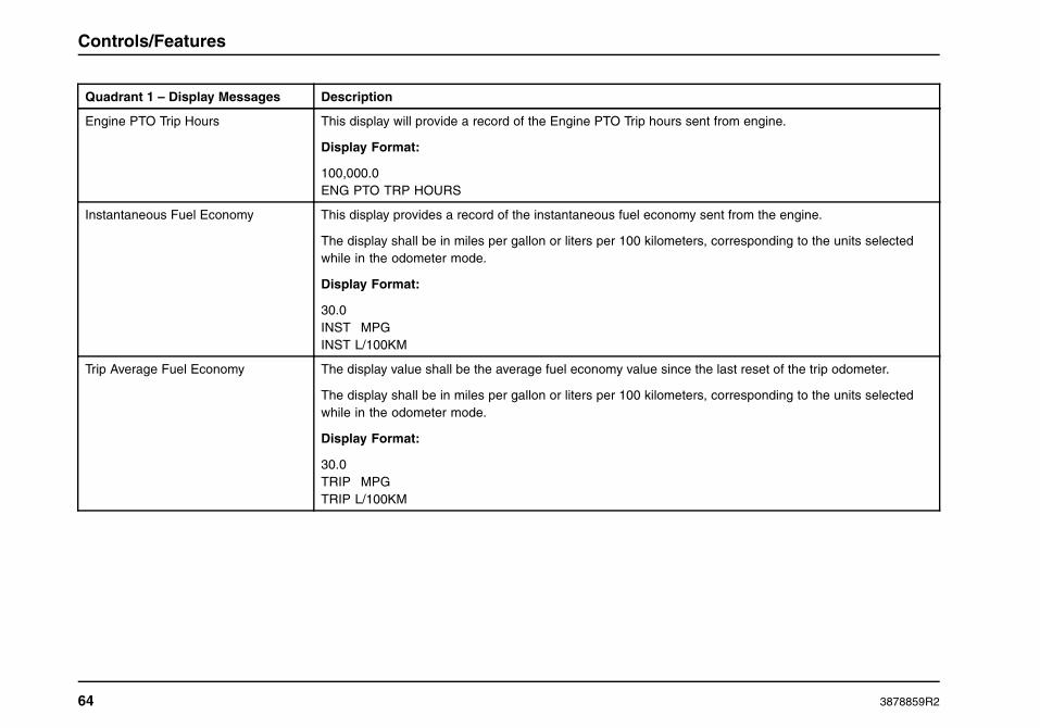
Controls/Features
Quadrant 1 – Display Messages Description
Engine PTO Trip Hours This display will provide a record of the Engine PTO Trip hours sent from engine.
Display Format:
100,000.0ENG PTO TRP HOURS
Instantaneous Fuel Economy This display provides a record of the instantaneous fuel economy sent from the engine.
The display shall be in miles per gallon or liters per 100 kilometers, corresponding to the units selectedwhile in the odometer mode.
Display Format:
30.0INST MPGINST L/100KM
Trip Average Fuel Economy The display value shall be the average fuel economy value since the last reset of the trip odometer.
The display shall be in miles per gallon or liters per 100 kilometers, corresponding to the units selectedwhile in the odometer mode.
Display Format:
30.0TRIP MPGTRIP L/100KM
64 3878859R2

Controls/Features
Quadrant 1 – Display Messages Description
Machine PTO Fuel Used A and B The display value shall be the calculated Machine PTO Fuel Used.
Display Format:
100,000.0PTO GAL APTO GAL BPTO L APTO L B
Machine PTO Trip Fuel Used A and B The display value shall be the calculated Machine PTO Trip Fuel Used.
Display Format:
100,000.0PTO TRP GAL APTO TRP GAL BPTO TRP L APTO TRP L B
Engine PTO Fuel Used The display value shall be the calculated Engine PTO Fuel Used.
Display Format:
100,000.0ENG PTO GALPTO TRP L
3878859R2 65
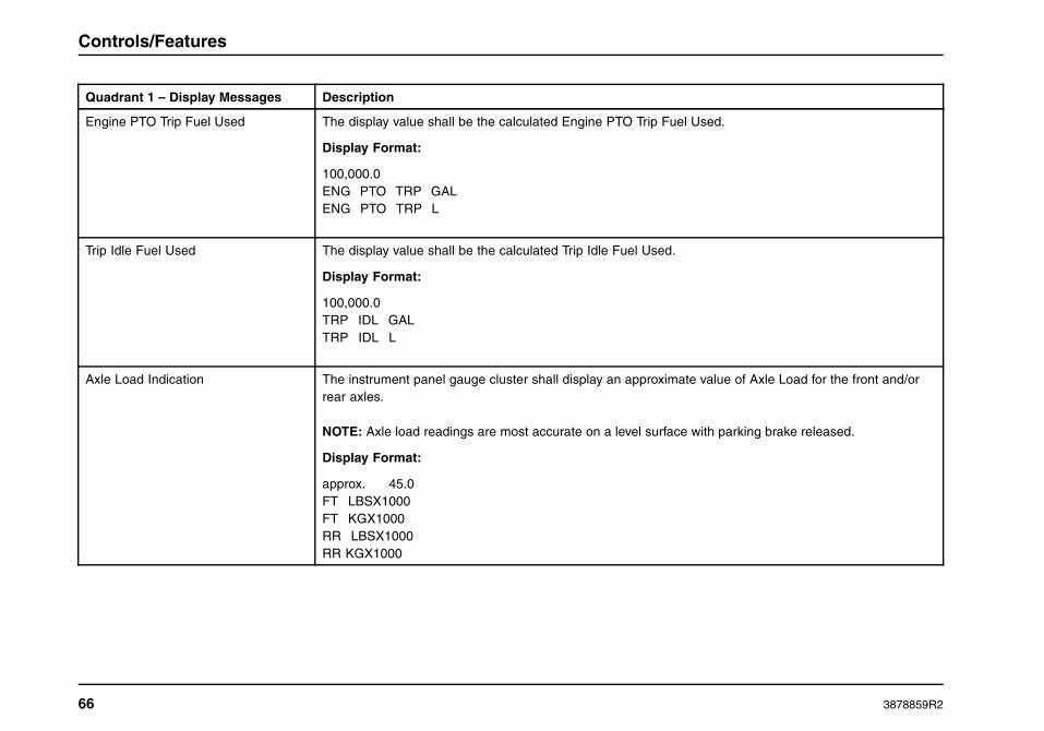
Controls/Features
Quadrant 1 – Display Messages Description
Engine PTO Trip Fuel Used The display value shall be the calculated Engine PTO Trip Fuel Used.
Display Format:
100,000.0ENG PTO TRP GALENG PTO TRP L
Trip Idle Fuel Used The display value shall be the calculated Trip Idle Fuel Used.
Display Format:
100,000.0TRP IDL GALTRP IDL L
Axle Load Indication The instrument panel gauge cluster shall display an approximate value of Axle Load for the front and/orrear axles.
NOTE: Axle load readings are most accurate on a level surface with parking brake released.
Display Format:
approx. 45.0FT LBSX1000FT KGX1000RR LBSX1000RR KGX1000
66 3878859R2
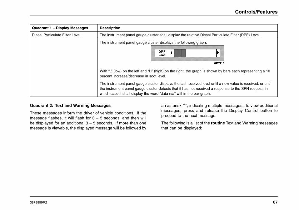
Controls/Features
Quadrant 1 – Display Messages Description
Diesel Particulate Filter Level The instrument panel gauge cluster shall display the relative Diesel Particulate Filter (DPF) Level.
The instrument panel gauge cluster displays the following graph:
With “L” (low) on the left and “H” (high) on the right, the graph is shown by bars each representing a 10percent increase/decrease in soot level.
The instrument panel gauge cluster displays the last received level until a new value is received, or untilthe instrument panel gauge cluster detects that it has not received a response to the SPN request, inwhich case it shall display the word “data n/a” within the bar graph.
Quadrant 2: Text and Warning Messages
These messages inform the driver of vehicle conditions. If themessage flashes, it will flash for 3 – 5 seconds, and then willbe displayed for an additional 3 – 5 seconds. If more than onemessage is viewable, the displayed message will be followed by
an asterisk “*”, indicating multiple messages. To view additionalmessages, press and release the Display Control button toproceed to the next message.
The following is a list of the routine Text and Warning messagesthat can be displayed:
3878859R2 67

Controls/Features
Quadrant 2 – DisplayMessages
Description Flash (Yes/No) Warning IndicatorAssociation
Parkd Regen Active Message is displayed during a parked regeneration. No No
Load Shedding Message is displayed when electrical load control andshedding feature is implemented.
Yes No
Washer Fluid Low Indicates low washer fluid level. Yes No
Electrical Fault When instrument panel gauge cluster’s ability to displaydiagnostic codes is enabled, this message is displayedwhen there are active diagnostic codes.
Yes No
Check A/C Indicates a fault in the HVAC System. Yes No
Parkd Regen Inhibited Message is displayed when parked regeneration has beenrequested, but is not performed due to a vehicle interlockor an engine fault.
No No
Air Filter Restriction Message displayed indicates restricted air flow to theengine.
Yes No
Exterior Lamp Check Active Message displayed indicates Exterior Lamp Check is inprogress.
Yes No
HVAC Temp Setting Bar graph displayed show temperature setting in low tohigh increments.
No No
Activate HVAC Front Blower Bar graph displayed show blower speed setting in Off andlow to high increments.
No No
68 3878859R2

Controls/Features
Quadrant 2 – DisplayMessages
Description Flash (Yes/No) Warning IndicatorAssociation
HVAC Sleeper Blower Speed Bar graph displayed show blower speed setting in Off andlow to high increments.
No No
Air Pressure Diagnostic Yes No
Cruise Indicates that the Cruise Control System is turned On. No No
Fuel Filter Indicates that the fuel filter is clogged. Yes No
Check Brake Switch Yes No
Check Exterior Lamps Yes No
Engine Control Shutdown Yes No
Check Trailer Lights Yes No
Engine Control System Error Yes No
Parkd Regen Required Indicates parked regeneration is necessary. No No
Parkd Regen Inhibited Eng Tmp Message is displayed when engine coolant temperature isbelow 170° F (76.6°C).
No No
Regen Inhibit Switch Active Message is displayed when Regen Inhibt Switch is “On”and regeneration Is disabled.
No No
Parkd Regen Available No No
Low Coolant Level Message is displayed when coolant level is less than orequal to 80%.
Yes No
Stop Engine Message is displayed when Red Stop indicator isilluminated.
Yes Red warning indicator
3878859R2 69

Controls/Features
Quadrant 2 – DisplayMessages
Description Flash (Yes/No) Warning IndicatorAssociation
Warn Engine (Priority 1 or 2) (1) Message is displayed when MaxxForce® 11, 13, or 15ECM turn on the Red warning indicator.
(2) Message is displayed when MaxxForce® 11, 13, or 15ECM requests the Yellow warning indicator and not theRed warning indicator.
Yes (1) Red warning indicator
(2) Yellow warningindicator
Stop Hybrid Message is displayed when Hybrid system turns on andrequests the Red warning indicator.
Yes Red warning indicator
HV Batt Off-Line Message is displayed when Hybrid system battery is offline.
Yes No
Check Hybrid Message is displayed when Hybrid system turns on theYellow warning indicator while conditions for “HV BattOff-Line” message are not met.
Yes Yellow warning indicator
Low Engine Oil Level Message is displayed when engine oil level is less thanor equal to 80%.
Yes No
Change Engine Oil Message is displayed when engine oil change is detectedas necessary.
Yes No
Water in Fuel *Message is displayed when water in fuel is present. Yes No
Refuel Message is displayed when fuel level is low. MaxxForce®11, 13, or 15 engines only.
Yes No
High Fuel Temp Message is displayed when fuel temp is high. MaxxForce®11, 13, or 15 engines only.
Yes No
Electrical Fault (Priority 1 or 2) (1) Message is displayed when when EGC requests theRed warning indicator.
(2) Message is displayed when when EGC requests theYellow warning indicator.
Yes (1) Red warning indicator
(2) Yellow warningindicator
70 3878859R2

Controls/Features
Quadrant 2 – DisplayMessages
Description Flash (Yes/No) Warning IndicatorAssociation
Check Trans Message is displayed when transmission needs to beserviced.
Yes Yellow warning indicator
Trans Temp Message is displayed when transmission turns onthe Yellow warning indicator. Not available with alltransmissions.
Yes Yellow warning indicator
Gen Trns Flt Message is displayed when transmission turns on RedStop, MIL, or PROTECT, or the Yellow Warning indicatorwithout the conditions to display Check Trans, Trans Temp,Trans Oil Life, Trans Oil Filter, or Trans Service. Notavailable with all transmissions.
Yes Yes (see description)
Trans Oil Life Message is displayed when transmission oil needschanged. Not available with all transmissions.
Yes No
Trans Oil Filter Message is displayed when transmission oil needschanged. Not available with all transmissions.
Yes No
Trans Service Message is displayed when transmission needs service.Not available with all transmissions.
Yes No
DPF Ash Service Required Message is displayed when diesel particulate filter ashlevel requires service/cleaning.
Yes No
See Visor For Info Message is displayed indicates the particulate trapindicator must be on or must flash.
Yes Yes (see description)
3878859R2 71

Controls/Features
Quadrant 2 – DisplayMessages
Description Flash (Yes/No) Warning IndicatorAssociation
ECM, TCM, Shift Selector, ABS,Retarder – Driveline, EGC,Compass Module, ESC, VSM,SD, AGSP, TPMS, ExhaustModule, Telematics, AGSP 2,SIC 2, AGSP 3, SIC 1, PAM,Hybrid, Service Tool, Global
Message is displayed when a module other than the enginerequests the red stop warning indicator.
Yes Red warning indicator
ECM, TCM, Shift Selector, ABS,Retarder – Driveline, EGC,Compass Module, ESC, VSM,SD, AGSP, TPMS, ExhaustModule, Telematics, AGSP 2,SIC 2, AGSP 3, SIC 1, PAM,Hybrid, Service Tool, Global
Message is displayed when a module other than the enginerequests the Yellow warning indicator.
Yes Yellow warning indicator
Retarder Temp Message is displayed when instrument panel gauge clusterreceives signal from the Retarder – Driveline requestingthe Yellow warning indicator.
Yes Yellow warning indicator
Gen Rtrd Flt Message is displayed when instrument panel gauge clusterreceives signal from the Retarder – Driveline requestingthe Red warning, MIL, or PROTECT indicator, or theYellow warning indicator without the conditions to displayRetarder Temp..
Yes Yes (see description)
DRV Reward Expected No No
DRV Reward Good No No
DRV Reward Excellent No No
DRV Reward Penalty No No
72 3878859R2

Controls/Features
Quadrant 2 – DisplayMessages
Description Flash (Yes/No) Warning IndicatorAssociation
DRV Reward Increasing No No
DRV Reward Decreasing No No
VSL Ovrd Active No No
VSL Ovrd Expiring No No
Blank screen, available only when engine rpm less thanor equal to 325 RPM, or vehicle speed less than 2 mph(3 km/h).
No No
Calibrate Compass Message is displayed when vehicle speed is less than2 mph (3 km/h) and the operator has not requested“Calibrate Compass” in the current ignition cycle.
No No
End Calibration Message is displayed when vehicle speed is less than 2mph (3 km/h) and the operator has requested “CalibrateCompass” in the current ignition cycle.
No No
Calibration Ended Message is displayed when vehicle speed is less than 2mph (3 km/h) and the operator has requested “CalibrateCompass” in the current ignition cycle.
No No
Declination Zone Message is displayed only when vehicle speed is less than2 mph (3 km/h).
No No
*If this message is displayed, drain water from fuel/water separator.
3878859R2 73
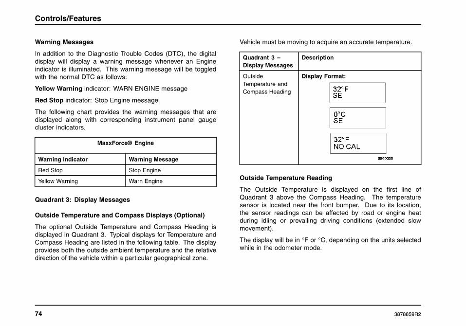
Controls/Features
Warning Messages
In addition to the Diagnostic Trouble Codes (DTC), the digitaldisplay will display a warning message whenever an Engineindicator is illuminated. This warning message will be toggledwith the normal DTC as follows:
Yellow Warning indicator: WARN ENGINE message
Red Stop indicator: Stop Engine message
The following chart provides the warning messages that aredisplayed along with corresponding instrument panel gaugecluster indicators.
MaxxForce® Engine
Warning Indicator Warning Message
Red Stop Stop Engine
Yellow Warning Warn Engine
Quadrant 3: Display Messages
Outside Temperature and Compass Displays (Optional)
The optional Outside Temperature and Compass Heading isdisplayed in Quadrant 3. Typical displays for Temperature andCompass Heading are listed in the following table. The displayprovides both the outside ambient temperature and the relativedirection of the vehicle within a particular geographical zone.
Vehicle must be moving to acquire an accurate temperature.
Quadrant 3 –Display Messages
Description
OutsideTemperature andCompass Heading
Display Format:
Outside Temperature Reading
The Outside Temperature is displayed on the first line ofQuadrant 3 above the Compass Heading. The temperaturesensor is located near the front bumper. Due to its location,the sensor readings can be affected by road or engine heatduring idling or prevailing driving conditions (extended slowmovement).
The display will be in °F or °C, depending on the units selectedwhile in the odometer mode.
74 3878859R2
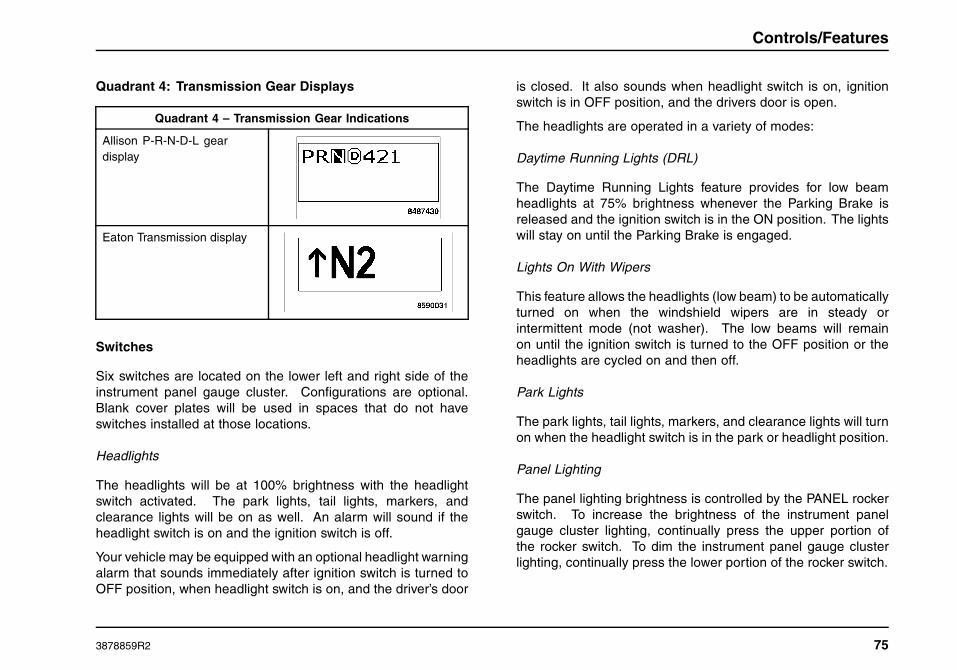
Controls/Features
Quadrant 4: Transmission Gear Displays
Quadrant 4 – Transmission Gear Indications
Allison P-R-N-D-L geardisplay
Eaton Transmission display
Switches
Six switches are located on the lower left and right side of theinstrument panel gauge cluster. Configurations are optional.Blank cover plates will be used in spaces that do not haveswitches installed at those locations.
Headlights
The headlights will be at 100% brightness with the headlightswitch activated. The park lights, tail lights, markers, andclearance lights will be on as well. An alarm will sound if theheadlight switch is on and the ignition switch is off.
Your vehicle may be equipped with an optional headlight warningalarm that sounds immediately after ignition switch is turned toOFF position, when headlight switch is on, and the driver’s door
is closed. It also sounds when headlight switch is on, ignitionswitch is in OFF position, and the drivers door is open.
The headlights are operated in a variety of modes:
Daytime Running Lights (DRL)
The Daytime Running Lights feature provides for low beamheadlights at 75% brightness whenever the Parking Brake isreleased and the ignition switch is in the ON position. The lightswill stay on until the Parking Brake is engaged.
Lights On With Wipers
This feature allows the headlights (low beam) to be automaticallyturned on when the windshield wipers are in steady orintermittent mode (not washer). The low beams will remainon until the ignition switch is turned to the OFF position or theheadlights are cycled on and then off.
Park Lights
The park lights, tail lights, markers, and clearance lights will turnon when the headlight switch is in the park or headlight position.
Panel Lighting
The panel lighting brightness is controlled by the PANEL rockerswitch. To increase the brightness of the instrument panelgauge cluster lighting, continually press the upper portion ofthe rocker switch. To dim the instrument panel gauge clusterlighting, continually press the lower portion of the rocker switch.
3878859R2 75

Controls/Features
Dome Lighting
The overhead dome light is used for reading and for illuminationwhen entering and exiting the vehicle. The dome light on/offis also controlled by pushing on the lamp lens. When eitherentrance door is closed, the courtesy light will remain ON forapproximately 20 seconds or until the ignition switch is turnedON. At that time, the lights will dim gradually until the light is off.The Optional keyless entry key fob also turns on the light for atime period when the Unlock button is pressed, and turns off thelight (dims gradually to off) when the Lock button is pressed.
Courtesy Lights
Either the driver or the passenger door activates thedoor-mounted courtesy lights to add light when getting inor out of the truck.
ItemNo.
Item Description
49 Enables Auto Headlights in vehiclesequipped with this feature.
50 Used to turn work lights on and off.
51 Headlight/Park Lamp Switch
Activates the headlight or parking lights,and illuminates the instrument panelgauge cluster. This switch functionseven when ignition switch is turned off(a warning will sound when this switch isON and the ignition switch if OFF).
52 Panel Dimmer
Adjusts the panel lights brightness.
53 Used to turn cab dome light on and off andmake it possible to activate/deactivatethe dome light when opening the doors.
54 Used to either turn on the sleeper domeor floor light.
76 3878859R2

Controls/Features
Steering Wheel Controls
The steering wheel contains a variety of push-button switches toaid in the operation of the vehicle.
1 SET/COAST - Used to set the speeddesired on the cruise control or coast toa lower desired speed. When parked,used to decrease idle RPM.
2 HEADLIGHT INT - Used to momentarilyturn off (interrupt) the headlights whenpressed.
3 RESUME/ACCEL - Used to resume thedesired speed set on the cruise controlor accelerate to a higher desired speed.When parked, used to increase idleRPM.
4 OFF/ON - Used to turn the cruise controlON and OFF.
5 HORN - Used to activate the city horn.
6 RADIO (Optional) - Adjusts radiovolume (+/-) and station selection(< >) with the radio turned on.
7 AIR HORN - Used to activate the airhorn.
8 MARKER INT - Used to toggle the parklights and markers on or off, dependingon park light switch position. If the parklights are on, it will toggle them off. If thepark lights are off, it will toggle them on.
3878859R2 77

Controls/Features
9 ENG BRAKE ON/OFF (Optional) - Usedto turn engine brake on or off.
10 AUTO/MAN +/- (Optional) - Allowsdriver to select higher or lower gear ofautomatic transmission.
Cruise Control
WARNING
Do not use the cruise control system whenunpredictable driving conditions are present.Such conditions include heavy traffic, roadsthat are winding, icy, snow covered, slippery,or with a loose surface. These conditions maycause wheel slippage and loss of vehicle control,resulting in property damage, personal injury, ordeath.
a. Press the ON position of the ON/OFF steering wheelcontrol.
b. Bring the vehicle to the desired operating speed (above35 MPH), and push the SET/COAST position of thesteering wheel control.
c. Once in the cruise mode, the RESUME/ACCEL switchcan be used to increase or decrease vehicle speed bypressing and holding the RESUME/ACCEL to increasethe speed, or by pressing and holding the SET/COASTto decrease vehicle speed.
d. A slight tap on the brake or clutch pedal will deactivatethe cruise but hold the selected speed in memory.To return to the predetermined speed, press theRESUME/ACCEL switch.
e. When you press the OFF position of the ON/OFF switch,or if the vehicle is shut off, the selected speed setting iscanceled and removed from memory.
Steering Column and Switches
The steering column contains switches and levers to aid in thecomfort of the operator and to assist the operator while drivingthe vehicle.
78 3878859R2
Controls/Features
1. Tilting and Telescoping Adjustment Lever - Allows thesteering wheel placement to be adjusted for driver comfort. Pushdown to adjust, pull up to lock.
2. Hazard Warning Switch - Red rocker switch located abovemultipurpose turn signal lever. Push switch to forward position toactivate. The hazard warning flasher will operate with the ignitionswitch in the ON or OFF position. Use the warning system anytime your vehicle becomes a traffic hazard, day or night. Pushswitch rearward to deactivate.
Stop Override Hazard (Optional) - When hazard lights areactivated and the brake pedal is depressed, all hazard/turnsignal lights on the front, side lights of the truck, and the sidetrailer lights will continue to flash. The rear lights of the truck ortractor will burn steadily until the brake is released.
3. Trailer Brake Lever - This lever is used to apply and releasethe brakes to the trailer.
Multi-function Switch - The multi-function turn signal switchis mounted on the left side of the steering column below thesteering wheel.
4. Signaling For A Turn - When signaling your intention to makea turn, move the turn signal lever up or down to the “full turn”position which is past the point of resistance. The switch doesnot automatically cancel and will require manual cancellation.
Lane Change – The turn signal lever includes a “lane change”feature which allows the operator to signal the intention tochange lanes without locking the switch into the full turnposition. To use this feature, move turn signal lever up or downto the point where resistance to movement is felt. The turnsignal lever will return to the off position when released.
5. Windshield Wiper - The electric wiper has two speeds(hi-low), which can be operated by rotating the WASHER/WIPERknob. The optional intermittent control provides five wiper on/offcycle intervals, varying from 2 to 14 seconds. This is done byrotating the wiper control from the wiper OFF position to the anyof the five intermittent wiper interval positions.
Automatic Intermittent Interval Control (Optional) – Thisfeature automatically changes the wiper speed from HIGH orLOW to the slowest intermittent speed when the parking brakehas been set, and the wipers have been on for a predeterminedlength of time. When the parking brake is released, the wipersreturn to their previous speed.
WARNING
Do not use the washers in freezing weatherwithout first warming the windshield with thedefrosters; otherwise, the washer solution mayfreeze on the windshield and obscure your visionand cause an accident which could result inproperty damage, personal injury, or death.
Do not use radiator coolant or antifreeze in thewindshield washer reservoir. Radiator coolantin the washer reservoir can severely reducevisibility when sprayed on the windshield.
Keep the fluid reservoir filled with Fleetrite Windshield WasherSolvent or equivalent.
6. Low/High Beam - When the turn signal stalk is pulled pastthe “click” position, lights will switch to Hi-Beam position. Whenpulled again they will revert to Lo-Beam.
3878859R2 79

Controls/Features
Headlight Flash-To-Pass - When the turn signal lever is pulledwith the headlights OFF, the Hi-Beam lights will come on and stayon as long as the lever is held in the pulled position. When theLo-Beam headlights are ON, the Hi-Beam lights can be madeto flash if the lever is not lifted past the click or dimmer position.When the Hi-Beam headlights are ON, the Lo-Beam lights canbe made to flash if the lever is not lifted past the click or dimmerposition.
7. Washer/Wiper Control - The windshield washer, along withthe windshield wipers, is controlled by the WASHER/WIPERknob on the turn signal switch lever. To operate the windshieldwasher, push in on the wiper knob to spray solution on thewindshield. Wipers will start wiping and continue for two cycles.
80 3878859R2

Controls/Features
Center Dash Panel/Wing Panel
3878859R2 81

Controls/Features
Gauges
There are four optional gauges in the instrument panel gaugecluster of the center dash panel to help monitor the vehicle whilein service.
ItemNo.
Item Description
1 Provides reading of brake applicationair pressure in pounds per square inch(PSI).
2 Provides monitoring of temperature offorward-rear axle lubricant in degreesFahrenheit (°F).
3 Provides monitoring of temperatureof rear-rear axle lubricant in degreesFahrenheit (°F).
4 Provides reading of turbocharger boostpressure in pounds per square inch(PSI).
Switches
Up to 23 optional switches can be located in the center and lowerright side of the center dash panel. Location of these switcheswill vary depending on the options installed. Blank cover plateswill be used in spaces that do not have switches installed at thoselocations.
Item No. Item Description
5 MIR HEAT/ON
A momentary switch that, whenpushed and released, turns the mirrorheating element ON/OFF.
6 SLPR TEMP
Controls the temperature in the sleepercompartment.
7 SLPR FAN
Controls the on/off and fan speed ofthe temperature control in the sleepercompartment.
8 ENG BRAKE 1/2/3
A three position switch that selects theamount of engine braking (1 = Low, 2= Medium. 3 = High)
82 3878859R2

Controls/Features
9 FOG LIGHT/ON
Turns on Fog Lamps when headlightswitch is on, and high beams are off.
10 OFF ROAD (Bendix)
This switch enables and disables theABS traction control feature.
MUD/SNOW (Wabco)
This switch enables and disables theABS traction control feature.
11 FAN OVRD/ON
With the switch in the “ON” position,the engine fan mode is switched fromauto to the constant on.
12 PDL LOCK
This switch is used to lock togetherthe front and rear axle of a tandem forimproved traction at low speeds onlow-traction surfaces.
13 SUSP/DUMP
This switch allows the operator torelease the air from the air bags in arear air suspension system when thevehicle’s speed is less than 5 mph.
14 PTO OFF/ON
Used when vehicle has single PTOoption.
PTO A OFF/ON
Used when vehicle has dual PTOoption.
15 PTO B OFF/ON
Used when vehicle has dual PTOoption.
16 5TH WHEEL/SLIDE
This momentary switch, when held on,releases the sliding 5th wheel (whenignition switch is in ON and vehiclespeed is less than 2 mph).
3878859R2 83

Controls/Features
17 FIFTH WHEEL JAW UNLOCK
Press and hold this momentary switchto unlock the fifth wheel jaw. Vehiclemust be stationary, parking brake set,and ignition switch in the RUN position.
5TH WHEEL JAW MONITORINGLOCK/UNLOCK
These switches activate an electronicjaw lock indicator system showing fifthwheel jaw status to the operator.
18 DIFF/LOCK
Used when vehicle has single lockingdifferential for improved traction onpoor surfaces at low speeds.
DIFF FR AXLE/LOCK
Locks forward rear drive axledifferential when vehicle has 6x4independent locking differentials forimproved traction on poor surfaces atlow speeds.
19 DIFF RR AXLE/LOCK
Locks rear drive axle differential whenvehicle has 6x4 independent lockingdifferentials for improved traction onpoor surfaces at low speeds.
20 PARKD REGEN/ON
DPF regeneration activation whenparked switch is used for engineafter-treatment. Manually initiates DPFregeneration.
21 INHIBT REGEN/ON
The Regeneration Inhibit switch is usedto prevent the Normal Regeneration orParked Regeneration processes.
22 SLPR ENGINE CNTL
Sleeper engine control switch is usedwhen the vehicle has remote start.Allows the remote engine start/stop viaa switch on the sleeper control panel.
23 TRLR AUX/ON
Auxiliary trailer socket center pincontrol.
84 3878859R2

Controls/Features
24 SPARE/ON
Spare switch provided for customerusage of additional options.
25 QUAL-COM/PANIC
Sends distress signal.
Used in conjunction with the (optional)Qualcomm satellite communicationsystem – see Qualcomm SystemOwner’s Manual.
ENAB/DATA LOG
When enabled, allows the driver to logthe last five seconds of data group’soperational parameter values intoECM memory.
The center dash panel also consists of console components fordriver comfort and use, as well as the transmission controls andVehicle Information Display.
26. Auxiliary Power Connectors
27. Cup Holder/Ashtray
28. Ignition
29. Cigarette Lighter
30. Accessory Power Outlet
31. Manual Transmission Shift Lever
32. Dash Vehicle Information Display (optional)
33. Air Brake Valve Controls
a. Trailer Air Supply
b. Parking Brake
34. Radio/Stereo
35. Automatic Transmission Push-Button Shifter (optional)
3878859R2 85

Controls/Features
Climate Control
WARNING
Never drive the vehicle unless the windshield and all other windows are clear. A fogged, ice/snow covered, or dirty windshieldor window limits vision, which could cause an accident, resulting in property damage, personal injury, or death. To improvedefroster efficiency, remove ice and/or snow by hand from the windshield and windows with a non-metallic scraper.
CAUTION
To clear system of humid air, operate blowers for 30 seconds at high speed, with the AIR FLOW/AIR CONDITIONER knob on thenormal heating position before selecting the DEF position. This will prevent fogging the glass, which can occur if humid air isblown onto a cool windshield.
NOTE: The vehicle may be equipped with heater shut off valve(s) to prevent hot coolant from circulating through the heater core(s). Closing thevalve(s) during hot weather operation will improve A/C system performance. If the valves are shut off, in-cab temperature adjustment may becomelimited. In addition, when shut off valves are closed defrosters will only produce cold air.
Item No. Item Description
36 Fan Speed Control Use this control to regulate the amount of air provided to the vents in any mode you select. Turnthe knob clockwise to increase fan speed. Turning the control to the “OFF” position will shut off thefan, but does not prevent outside air from entering the vehicle. On vehicles equipped with A/C,moving the mode knob to the “MAX A/C” position will close the fresh air door eliminating outsideair from entering the vehicle. Turning off the fan speed control also turns off the A/C compressor.
37 Temperature Control Use this control to regulate the temperature of the air discharged from the vents. The blue area ofthe control indicates cooler temperatures while the red area indicates warmer temperatures.
38 Mode Control NOTE: The dot between the mode control icons is an additional mix position between the twomodes.
Use this control to direct the flow of air as follows:
86 3878859R2

Controls/Features
MAX Air Conditioning Mode
In this mode all airflow is directed to the panel air outlets and the air is recirculated inside thevehicle. Use this mode to block out any outside odors, smoke, or dust and to cool the interiorrapidly upon initial start up in very hot or humid weather.
NOTE: Continuous use of the recirculate mode may make the inside air stuffy. Use of this mode forlonger than fifteen minutes is not recommended.
The A/C compressor turns on and off automatically as needed when in this mode.
NORM Air Conditioning Mode
In this mode all airflow is directed to the panel air outlets. Fresh (outside) air is used to cool thevehicle in this mode.
The A/C compressor turns on and off automatically as needed when in this mode.
Bi-Level Air Conditioning Mode
In this mode 75% of the airflow is directed to the panel air outlets and 25% of the airflow is directedto the floor air outlets, and fresh (outside) air is circulated inside the vehicle.
The A/C compressor turns on and off automatically as needed when in this mode.
Vent Mode
In this mode all airflow is directed to the panel air outlets and fresh (outside) air is circulatedinside the vehicle.
Floor Mode
In this mode all airflow is directed to the floor air outlets and fresh (outside) air is circulated insidethe vehicle.
3878859R2 87

Controls/Features
Mix Mode
In this mode 50% of the airflow is directed to the defrost and side demist air outlets and 50% of theairflow is directed to the floor air outlets, and fresh (outside) air is circulated inside the vehicle.
The A/C compressor turns on and off automatically as needed when in this mode to reducehumidity levels and help reduce moisture buildup on the windshield.
Defrost
In this mode all of the airflow is directed to the defrost and side demist air outlets and fresh(outside) air is circulated inside the vehicle.
The A/C compressor turns on and off automatically as needed when in this mode to reducehumidity levels and help reduce moisture buildup on the windshield.
To remove stale air or smoke while air conditioner is operating, you may want to open a vent window for a short period of time. Always park inthe shade when possible. If your vehicle has been parked in the sun with the windows up, remove the overheated air inside by driving withwindows down and the air conditioner ON for one or two city blocks.
Air Conditioning
CAUTION
Failure to follow recommended serviceprocedures and maintain adequate air flowthrough air exchange devices may resultin component failure. Cleaning should beperformed by a qualified technician.
Keep radiator area free of bugs, leaves etc. Do not cover thecondenser with a wire screen.
At least once or twice a month turn on the air conditioner for afew minutes while the engine is running. This periodic operationkeeps all the mechanical parts of your air conditioner in goodoperating condition.
It is normal for small amounts of water to drain out of the airconditioner module. This water is condensed moisture removedfrom the air inside the vehicle.
Correct airflow may be restored by either replacing the filter(s),which can be done without tools, or by cleaning the filters. Thefilter(s) may be cleaned by using a power washer with a soapsolution. Keep the spray head at least six inches away from thefilter to avoid damage. Rinse thoroughly.
NOTE: If your air conditioning performance seems lowerthan expected, check the front of the A/C condenser for anaccumulation of dirt or insects. Clean with a gentle water sprayfrom behind the radiator and through the condenser as required.Check for dirt and debris in both the cab and sleeper HVACintake filters that may reduce airflow.
88 3878859R2

Controls/Features
Dehumidification
The heater-defroster systems can be operated simultaneouslywith the air conditioner during mild weather and high humidityconditions to dehumidify the cab air. Turn the mode button toone of the A/C positions and position the temperature knob ata comfortable temperature location. The air conditioner willremove the humidity while the heater keeps the cab comfortable.
Electronic Vehicle Monitoring
Base Display
The optional Electronic Vehicle Monitoring Driver InformationDisplay provides trouble code reporting, trip status, vehicle
and engine usage, fuel economy information, video inputsfor external cameras and a USB port for loading MP3 audiofiles that can be played through the radio. This unit alsoprovides an interface for the optional SmartWave® tire pressuremanagement system and a port that is compatible withthe optional Qualcomm Omnivision system. Refer to theDriver Information Display operator reference card, or visithttp://www.lectronix.biz/support.html for additional information.
Premium Display
The optional Premium display is the same as the Base unit,but with an additional navigation feature. This feature providesmapping features, turn-by-turn directions, and truck points ofinterest.
SmartWave® Display
The optional SmartWave® tire alerts and warnings displayhas three automated tire alerts to instantly warn the driver ofan underinflated tire before it becomes dangerous; pressure
3878859R2 89
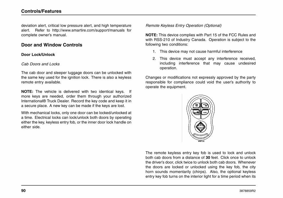
Controls/Features
deviation alert, critical low pressure alert, and high temperaturealert. Refer to http://www.smartire.com/support/manuals forcomplete owner’s manual.
Door and Window Controls
Door Lock/Unlock
Cab Doors and Locks
The cab door and sleeper luggage doors can be unlocked withthe same key used for the ignition lock. There is also a keylessremote entry available.
NOTE: The vehicle is delivered with two identical keys. Ifmore keys are needed, order them through your authorizedInternational® Truck Dealer. Record the key code and keep it ina secure place. A new key can be made if the keys are lost.
With mechanical locks, only one door can be locked/unlocked ata time. Electrical locks can lock/unlock both doors by operatingeither the key, keyless entry fob, or the inner door lock handle oneither side.
Remote Keyless Entry Operation (Optional)
NOTE: This device complies with Part 15 of the FCC Rules andwith RSS-210 of Industry Canada. Operation is subject to thefollowing two conditions:
1. This device may not cause harmful interference
2. This device must accept any interference received,including interference that may cause undesiredoperation.
Changes or modifications not expressly approved by the partyresponsible for compliance could void the user’s authority tooperate the equipment.
The remote keyless entry key fob is used to lock and unlockboth cab doors from a distance of 30 feet. Click once to unlockthe driver’s door, click twice to unlock both cab doors. Wheneverthe doors are locked or unlocked using the key fob, the cityhorn sounds momentarily (chirps). Also, the optional keylessentry key fob turns on the interior light for a time period when its
90 3878859R2

Controls/Features
Unlock button is pressed, and turns off the light (dims graduallyto off) when its Lock button is pressed. The Panic (emergency)button, when pushed, causes the horn to chirp on/off for threeminutes, in unison with the headlights and park lights flashing.This feature works only when the ignition switch is in the OFFposition.
Lock/Unlock From Interior
WARNING
To help reduce the risk of personal injury in theevent of an accident, keep doors locked whenvehicle is in motion.
1. Lock/Unlock Button
2. Door Control Panel
3. Driver Side Power Window Control
4. Passenger Side Power Window Control
5. Window Lock Control
Locking the Door
To lock, push the lock/unlock button on the lock symbol in thedoor control panel located by the vent window. Pressing thelock/unlock button on the lock symbol once locks both cab doors.
Unlocking the Door
To unlock, push the lock/unlock button on the unlock symbol inthe door control panel located by the vent window. Pressing thelock/unlock button once on the unlock symbol unlocks the driverdoor. Pressing it twice unlocks both doors.
Automatic Door Lock Function
The automatic lock function automatically locks the doors at apredetermined speed.
Driver/Passenger Windows
Manual Operation
To lower door glass (driver door), turn window regulator handleclockwise. To raise glass, turn handle counterclockwise.Reverse this procedure for the passenger door.
3878859R2 91

Controls/Features
Power Operation
Trucks may have optional electrically operated driver andpassenger windows. Controls for these window lifts aremounted in the door control panels located by the vent windows.The driver side controls regulate window operation for bothdriver and passenger. To lower or raise driver window, pressand hold either “Up” or “Down” direction on the driver side AUTOwindow control. To lower or raise passenger window, pressand hold either “Up” or “Down” direction on the passenger sideAUTO window control.
For one touch windows down operation, press and release thewindow control in the “Down” direction. The window will then goto the full down position automatically.
Window Lockout Function
The driver also has the ability to prevent passenger windowup/down operation by pressing the WINDOW LOCK control.
Mirror Controls
1. Mirror Select Switch
2. Mirror Direction Control Switch
These controls provides the driver with the ability to operate bothdriver and passenger-side flat mirrors. Use the mirror selectswitch to select which mirror is to be adjusted, and adjust themirror using the mirror direction control switch.
Vent Window
Vehicles are equipped with either a fixed or opening vent window.The opening vent window can be opened and closed to allowadditional air flow into the cab.
92 3878859R2

Controls/Features
Eaton VORAD Collision Warning System(Optional)
WARNING
Before using this feature, read and thoroughlyunderstand the Eaton VORAD Collision WarningSystems Driver Instructions manual, and obtainproper training on the system. Improper use ofthis system could result in property damage,personal injury, or death.
WARNING
The Eaton VORAD Collision Warning Systemis intended solely as an aid for an alert andconscientious professional driver. It is not tobe used or relied upon to operate a vehicle.The system should be used in conjunction withrear view mirrors and other instrumentation tomaintain safe operation. A vehicle equipped withthe Vorad Collision Warning System should beoperated in the same safe manner as if the VoradCollision Warning System were not installed.The system is not a substitute for normal safedriving procedures. It will not compensate forany driver impairment, such as drugs, alcohol, orfatigue. Failure to heed this warning may resultin property damage, personal injury, or death.
WARNING
The Eaton VORAD Collision Warning Systemmay provide little or no warning for somehazards, such as pedestrians, animals, oncomingvehicles, and cross traffic. Failure to heedthis warning could result in property damage,personal injury, or death.
System Description
The Eaton VORAD system uses forward-looking radar andoptional side-looking radar to constantly monitor vehicles aheadand in the blind spot area, respectively. The Vorad CollisionWarning System determines the distance and relative speed ofthe object in front of the vehicle to warn the driver of potentiallydangerous situations through visual and audible alerts. TheSmartCruise® feature works with the vehicle’s cruise controlsystem to attempt to automatically maintain a fixed followingdistance between the host vehicle and a vehicle ahead. TheSide Object Detection system can detect moving or stationaryobjects in the lane next to the vehicle and alert the driver of theirpresence.
Visual and audible alerts are provided by the Driver Interface Unitlocated in the dash panel where it is easily visible and accessible.Refer to the Driver Instruction manual for complete operatinginstructions.
Driver Reward
The driver reward feature is designed to give the operatorprogrammable incentives for driving more efficiently. This
3878859R2 93

Controls/Features
is accomplished by measuring the driver’s habits based onfuel economy, time at idle, or both. Rewards include highermaximum vehicle speed and higher cruise control speed limit.Lower maximum vehicle speed or cruise control speed limitsmay result as a penalty for failing to meet the standards.
The following driver reward visual indications appear in the formof text messages in the gauge cluster digital display:
• Expected – Reward indication which results in higher vehiclespeed limits.
• Good – Reward indication which results in higher vehiclespeed limits.
• Excellent – Reward indication which results in higher vehiclespeed limits.
• Penalty – Penalty indication which results in lower vehiclespeed limits.
• Increasing – Informs the driver that the vehicle speed limitwill soon be increased.
• Decreasing – Informs the driver that the vehicle speed limitwill soon be decreased.
94 3878859R2

Sleeper Features
SECTION 5 — SLEEPER FEATURES
Introduction
General Information
There are three trim versions of sleepers available, the ProStar®+Series, the ProStar®+ Eagle Series, and the ProStar®+ EagleSeries Suite. The International® ProStar®+ Series sleepercompartment comes in two sizes, 56-inch (142 cm) (short)sleepers and 73-inch (185 cm) (long) sleepers.
Main Features
The sleeper compartments are designed to accommodatedifferent needs and your sleeper may or may not be equippedwith all the features listed in this section.
1. Duct Work Vents
2. Rear Wardrobe Cabinet
3. Airline Cabinets
4. Speakers
5. Control Panel
6. Cup Holders and Storage Trays
7. Lower Bunk
8. Under Bunk Storage Area
Common features on the International® ProStar®+ Series56-inch (142 cm) (short) sleeper model.
3878859R2 95

Sleeper Features
Common features on the International® ProStar®+ Series73-inch (185 cm) (long) sleeper model with lower bunk.
1. Duct Work Vents
2. Rear Wardrobe Cabinet
3. Airline Cabinets
4. Speakers
5. Control Panel
6. Tower Cabinet
Common features on the International® ProStar®+ Series73-inch (185 cm) (long) sleeper model with lower and upperbunks.
7. Lower Bunk
8. Under Bunk Storage Area
9. Refrigerator Cabinet or Dresser Cabinet
10. Upper Bunk
NOTE: Although not illustrated, the long sleeper models areequipped with the same cup holders and storage trays (bothends of lower bunk) as illustrated for the short sleeper model.
96 3878859R2
Sleeper Features
Lighting
Dome Light
The sleeper dome light is a large fluorescent light located onthe headliner of the sleeper compartment. The sleeper domelight can be controlled by switches located on the sleepercontrol panel and on the dash instrument panel. This two-switcharrangement permits the driver to turn the sleeper dome lighton or off before entering the sleeper area and turn the sleeperdome light on or off without having to go back to the cab area.
Reading Lights
The bunk reading light is positioned on the side panel, left side, toprovide illumination for easy reading. If the sleeper compartmentis equipped with the upper bunk option, a second reading light isprovided at the head of the upper bunk. Depressing the switchon the housing will turn the reading light on and off.
Floor Lights
There are two red floor lights located under the lower bunkincluded with all sleeper cabs. These floor lights are controlledby the same two-switch arrangement as the sleeper dome light.
Accent Lights
Convenient accent lights are located on the sleepercompartment headliner and provide an additional level ofillumination within the sleeper compartment. There are fouraccent lights in the long sleeper and two accent lights in theshort sleeper. Two switches are located on the sleeper controlpanel for controlling the accent lights.
• Accent Light Dimmer Switch: Used for adjusting thebrightness of the sleeper compartments accent lights.
• Accent Light Switch: Used for turning the accent lights onand off.
3878859R2 97

Sleeper Features
Sleeper Control Panel
General Information
The sleeper control panel comes with several optional featuresbut the main components are the switch pack, sleeper climatecontrols, and inverter control panel.
Sleeper Control Panel
ItemNo.
Component Description
1 Switch Pack The sleeper control panel is equipped withlocations for up to six switches.
2 ClimateControls
Manual heater, ventilation, and airconditioning (HVAC) Controls.
3 PowerReceptacle
Standard 12V power socket.
4 Radio RemoteControl
Can be used to control the functions of thedash mounted radio from the sleeper.
5 InverterControl Panel
The inverter control panel is used forcontrolling the power inverter that allowsthe use of items such as a TV, VCR,microwave, hair dryer, etc.
6 ClimateControls
Optional LED electronic heater, ventilation,and air conditioning (HVAC) Controls.
98 3878859R2
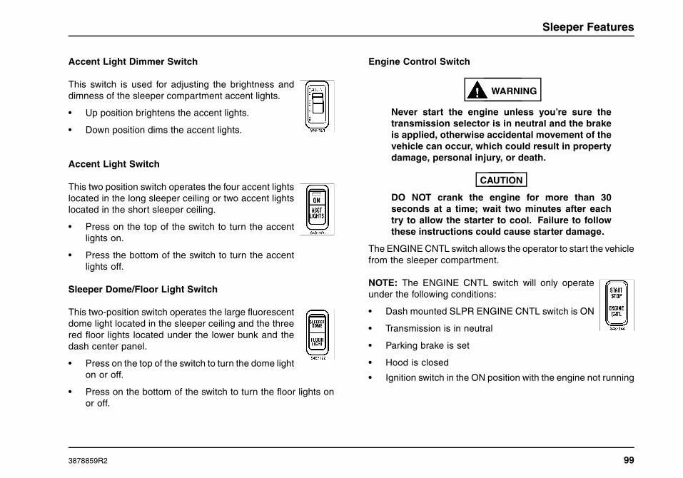
Sleeper Features
Accent Light Dimmer Switch
This switch is used for adjusting the brightness anddimness of the sleeper compartment accent lights.
• Up position brightens the accent lights.
• Down position dims the accent lights.
Accent Light Switch
This two position switch operates the four accent lightslocated in the long sleeper ceiling or two accent lightslocated in the short sleeper ceiling.
• Press on the top of the switch to turn the accentlights on.
• Press the bottom of the switch to turn the accentlights off.
Sleeper Dome/Floor Light Switch
This two-position switch operates the large fluorescentdome light located in the sleeper ceiling and the threered floor lights located under the lower bunk and thedash center panel.
• Press on the top of the switch to turn the dome lighton or off.
• Press on the bottom of the switch to turn the floor lights onor off.
Engine Control Switch
WARNING
Never start the engine unless you’re sure thetransmission selector is in neutral and the brakeis applied, otherwise accidental movement of thevehicle can occur, which could result in propertydamage, personal injury, or death.
CAUTION
DO NOT crank the engine for more than 30seconds at a time; wait two minutes after eachtry to allow the starter to cool. Failure to followthese instructions could cause starter damage.
The ENGINE CNTL switch allows the operator to start the vehiclefrom the sleeper compartment.
NOTE: The ENGINE CNTL switch will only operateunder the following conditions:
• Dash mounted SLPR ENGINE CNTL switch is ON
• Transmission is in neutral
• Parking brake is set
• Hood is closed
• Ignition switch in the ON position with the engine not running
3878859R2 99

Sleeper Features
To start the engine from the sleeper, press and hold the top of theENGINE CNTL switch. There will be a 15 second delay duringwhich an audible engine start alarm will sound then the enginewill begin cranking. Release the switch as soon as the enginestarts.
To stop the engine, press the ENGINE CNTL switch again.
Manual Climate Controls
NOTE: If sleeper air conditioning is desired and the main cabblower is not enabled, the air conditioner will not function and themessage Activate Front Blower will appear on the instrumentpanel gauge cluster.
The manual climate controls allow theoperator to adjust the temperature andamount of air circulated through thesleeper compartment.
1. Fan Control: Turns the fan on andoff, and controls the fan speeds.
NOTE: Fan speed will be limited to approximately 50% ofmaximum when the engine is not running.
2. Temperature Control: Use the temperature controlto regulate the temperature of the air inside the sleepercompartment. This temperature is independent of the cab area.The blue area indicates cooler temperatures and the red areaindicates warmer temperatures.
Electronic Climate Controller
NOTE: If sleeper air conditioning is desired and the main cabblower is not enabled, the air conditioner will not function and themessage Activate Front Blower will appear on the instrumentpanel gauge cluster.
The electronic climate controller provideseasy adjustments of the sleepers heatingand air conditioning system by using thebuttons.
1. Fan Control Buttons: Pressing theleft button repeatedly will lower the fanspeed to minimum, then turn the fan OFF.Pressing the right button turns the fan ON(if currently off), then raises the fan speedto maximum.
NOTE: Fan speed will be limited toapproximately 50% of maximum when the engine is not running.
2. Temperature Control Buttons: Use these buttonsto regulate the temperature of the air inside the sleepercompartment independent of the cab area. Press the leftbutton to lower the temperature and the right button to raise thetemperature.
3. Display: Allows the operator to view the settings for fan speedand air temperature as they are being adjusted.
NOTE: The temperature display is a representation of the currenttemperature set point, not actual sleeper temperature.
100 3878859R2

Sleeper Features
Power Receptacle
A 12 Volt power socket is located to the right of thesleeper climate controls. This power source providesa location to operate accessories.
Radio Remote Control
The radio remote control gives the operator the ability to operatethe dash-mounted radio from the sleeper compartment. Formore information on the radio remote control refer to the RadioManual.
Remote Power Inverter Panel
This optional feature allows the operatorto control the power inverter (if equipped)from the sleeper compartment. Thepower inverter converts 12 Volt DCcurrent to 120 Volt AC current for runningthe electrical features in the sleepercompartment.
1. ON/OFF Buttons: Press theSystem ON button to turn thepower inverter on and press theSystem OFF button to turn thepower inverter off.
2. Power Indicator Light: The power inverter light will beilluminated green when the power inverter is poweredon. A blinking green light indicates that the powerinverter is in standby mode and the batteries are beingcharged.
3. Fault Indicator Light: This light is used to notify theoperator that a fault exists with the power inverter. Asolid red light indicates the power inverter is in OverTemperature/Overload/or Battery Low Mode. No lightindicates that no fault exists.
For more information on the remote power inverter panel refer tothe Power Inverter Manual.
3878859R2 101

Sleeper Features
Windows
General Information
CAUTION
Make sure windows are closed before washingthe cab. Water can enter the cab through thewindow opening.
1. SleeperWindow
2. Handle
The sleeper compartment is equipped with a window on eachside that can be opened for ventilation.
• Lift the handle to open the window.
• Lower the handle to close and lock the window.
Optional privacy curtains are provided to cover the sleeperwindows. To install the curtains, place the curtain over thewindow and secure the curtain loops to the window frame.When not in use, store the curtains in one of the storagecompartments.
102 3878859R2

Sleeper Features
Bunk Restraint System
General Information
WARNING
Always use occupant restraint system whenvehicle is moving. Any location in the vehicle notequipped with a seat belt, bunk restraint belts,or sleeper berth restraint webbing should notbe occupied when the vehicle is being operated.In the event of a vehicle accident or sudden,unexpected movement, failure to properly usean occupant restraint system could result inpersonal injury or death.
Two types of sleeper bunk occupant restraint systems areavailable with sleeper bunks supplied by Navistar, Inc. If thesleeper berth is not provided with one of these two types ofrestraint systems, that bunk is not intended to be occupied whenthe vehicle is in motion and must not be used when the vehicleis being operated. The description and recommended usage ofthe two available restraint systems for sleeper berth areas areas follows:
Adjustable Belts
This two-belt system is standard with the sleeper lower bunk.To use the adjustable belt system, the bunk occupant shouldplace one belt across the lower body (positioned above theoccupants knees but below the hips), and the other belt shouldbe positioned across the upper body (above the hips butbelow the shoulders). Slack must be removed from belts afterconnecting the buckle by pulling the loose end of each belt to fitthe connected belt snugly across the occupant’s body.
Restraint Webbing System
The optional restraint webbing system is secured around thebunk with seven buckles. The only restraint system providedwith the optional upper bunk is the restraint webbing system. Touse the restraint webbing system follow these steps:
3878859R2 103

Sleeper Features
1. Bunk
2. Restraint Webbing System
3. Rear Latches
4. Rear Buckles
5. Font Latches
6. Front Buckles
7. Side Latch Plates
8. Side Buckles
9. Restraint Strap
To install the restraint webbing system onto the sleeper bunk:
1. Enter the bunk and lay the restraint webbing system outon top of your body.
2. Insert two rear latches on the rear wall into two matingbuckles (4) that are sewn to the restraint webbingsystem, making sure that both buckles are fully latched.
3. Insert three front latches that are sewn to the front of therestraint webbing system into the front buckles mountedat the front of the bunk, making sure that all three frontbuckles are fully latched.
4. The restraint webbing system is designed to be held upaway from the reclining bunk occupant by the adjustableside latch plates on each side of the restraint webbingsystem. Insert two side latch plates that are sewn to therestraint webbing system into the side mating buckleslocated on the sleeper compartment side walls.
5. To adjust the restraint webbing system, pull the shortstraps at the side latch plates on each side of therestraint webbing system to tighten. Loosen therestraint webbing system by raising the side latch platesaway from the restraint strap to allow the restraint strapto loosen through the latch plates.
6. Removal of the restraint webbing system is done byloosening both side latch plates, unlatching the sidelatch plates, unlatching the three buckles at the front ofthe bunk, and unlatching the two buckles attached tothe rear wall.
104 3878859R2

Sleeper Features
Lower Bunk
General Information
Upper and lower bunks are available in the International®ProStar®+ Series sleeper compartment. The lower bunk isstandard while the upper bunk is an option. The lower bunk ishinged for access to the features under the bunk. Gas shocksaid in opening and closing of the lower bunk and hold the bunkin the raised position for access.
ItemNo.
Component Description
1 ReleaseLatch
To open, press upward on the latch mechanismand lift the front edge of the bunk platform. Toclose, lower the bunk until the latch mechanismis locked in place.
2 Gas Shocks The lower bunk is fitted with two gas shocksto aid in opening, closing, and supporting thebunk in the opened position.
3 Lights The lower bunk has two automatic lights thatturn on as the bunk is raised and turn off whenthe bunk is lowered. These lights also operatewhen the exterior luggage doors are opened.
4 StorageTray
A removable storage tray is located under thecenter of the bunk and can easily be removedfrom its location once the bunk is opened.
5 Lock Boxes Two lock boxes are provided under the bunkstorage tray for securing valuables out of site.
6 PowerInverter
The optional power inverter is stored under thebunk in the center compartment.
7 SleeperHVACComponents
The sleeper heating, ventilation, and airconditioning (HVAC) components are storedunder the bunk.
8 LuggageCompartment
Access to the luggage compartments can beachieved from the interior with the lower bunkin the raised position.
3878859R2 105

Sleeper Features
9 SleeperHVACIntake
Allows air to enter sleeper HVAC unit. Do notblock HVAC air intake.
10 SleeperHVAC AirIntake Filter
Replaceable/cleanable filter cleans air andprotects heat exchanger from becomingplugged with lint and debris.
Upper Bunk
General Information
The optional upper bunk is hinged and can be raised and lockedout of the way. Brackets are located on each side wall to holdthe bunk in the down position and a latch is located on thepassenger side to hold the bunk or release it from its stowedposition. Access to the upper bunk is provided by steps that areattached to the driver side tower cabinet.
1. Release Latch
2. Upper Bunk Frame
3. Upper Bunk
NOTE: The sleeper compartment is equipped with a dome lightto aid entry and exit into the upper bunk. The dome light on/offswitches are located on the dash instrument panel and on thesleeper control panel.
106 3878859R2

Sleeper Features
Entering The Upper Bunk
1. Bottom Step
2. Airline Cabinet
3. Front Bunk Rail
4. Top Step
5. Upper Bunk
1. Begin by facing the bottom step, placing your right footon the bottom step, and grasp the front edge of theairline cabinet with your right hand and grasp the frontbunk rail with your left hand (The bunk area is designedfor your head to be at the driver’s side of the bunk).
2. Step up on the bottom step and place your left foot onthe top step while maintaining a firm grip on the frontedge of the airline cabinet with your right hand and thefront bunk rail with your left hand.
3. Release your right hand from the front edge of the airlinecabinets and grasp the front bunk rail.
4. Step up on the top step with both feet and while keepinga firm grip with both hands on the front bunk rail, swingyour right hip over onto the upper bunk.
5. Release your left hand from the front bunk rail and gripthe front edge of the upper bunk, along side your left hip.
6. Swing your legs up and to the right, positioning yourbody in the center of the upper bunk.
3878859R2 107

Sleeper Features
Exiting The Upper Bunk
1. Bottom Step
2. Airline Cabinet
3. Front Bunk Rail
4. Top Step
5. Upper Bunk
1. While keeping a firm grip with both hands on the frontedge of the upper bunk, sit up on the upper bunkpositioning your body above the top step and your legsover the front of the upper bunk.
2. Grab the front bunk rail with your right hand and the frontedge of the upper bunk with your left hand. Pivot yourbody to the left, swinging your left leg down, and placingyour left foot on the top step (4). Release the front bunkrail with your right hand and grasp the front edge of theairline cabinet.
3. Grab the front bunk rail with your left hand and front edgeof the airline cabinet with your right hand, and place yourweight on the top step. Step down with your right foot tothe bottom step.
4. Keeping a firm grip on the front bunk rail and the frontedge of the airline cabinet, step down to the cab floorwith your left foot followed by your right foot. You cannow release the front bunk rail and front edge of theairline cabinet.
108 3878859R2

Sleeper Features
Cabinets/Storage
General Information
WARNING
Always remove all loose items from the interiorand store appropriately when vehicle is in motion.Falling items can be a distraction to the driver ora projectile during an accident which could resultin personal injury or death.
NOTE: The following will describe and illustrate the standardcabinets and their storage functions for the International®ProStar®+ Series long sleeper. Your vehicle may not have all ofthese features.
The sleeper compartment is designed to accommodate severaldifferent types of cabinet configurations to fit all needs.
1. Optional Dresser Cabinet or Optional RefrigeratorCabinet
2. Airline Cabinets
3. Rear Wardrobe
4. Tower Wardrobe
3878859R2 109

Sleeper Features
Cabinets
Refrigerator Cabinet
1. Refrigerator Top: The top of the refrigerator cabinetserves as a desk top.
2. Release Knob: A release knob is used to open thework table. To open, depress the knob, the knob willextend from the work table, then pull the work tableopen. To close the work table depress the tab, alongthe forward side of the work table, and slide the worktable shut. Once the work table is closed the knobneeds to be pressed in to a flush position with the worktable (this prevents the knob from getting hung on yourclothing and other items as you move around in thesleeper compartment).
3. Lift Release Handle: The drawer is equipped with a liftrelease handle. To open the drawer, lift the handle fromthe bottom and slide the drawer open. To close, push thedrawer shut until the lift release handle locks the drawershut.
4. Door Lock: The door lock prevents the door fromopening while in motion. To unlock, push the door lockto the left. To lock the door, push the door lock to theright.
5. Door: The optional 1.7 cubic ft. refrigerator is equippedwith an adjustable thermostat, internal light, shelf, andsmall freezer for making ice. The door provides anattractive look to the refrigerator cabinet and hides therefrigerator.
6. Magazine Pocket: Provides a storage area for books,magazines, and maps.
7. Refrigerator Cabinet: The refrigerator cabinet isavailable on select International® ProStar®+ Series longsleeper models and is located behind the passenger’sseat.
110 3878859R2

Sleeper Features
8. Drawer: A small drawer is provided at the top of therefrigerator cabinet for storage.
9. Work Table: Pull-out work table. Important: A releaselatch is located on the right hand work table guide toallow the table to be stowed. To close simply depressthe release latch and slide the work table shut.
Horizontal Refrigerator
An optional horizontal refrigerator is available on selectInternational® ProStar®+ Series sleeper models and is locatedunder the lower bunk.
1. Control Knob/Thermostat
2. Power Indicator
3. Drawer
4. Refrigerator Cabinet
5. Lift Release Handle
Dresser Cabinet
1. Dresser Top: The top of the dresser cabinet serves asa desk top.
2. Release Knob: A release knob is used to open the worktable. To open, depress the knob, the knob will extendfrom the work table, then pull the work table open. Toclose the work table depress the tab, along the left sideof the work table, and slide the work table shut. Oncethe work table is closed the knob needs to be pressed into a flush position with the work table (this prevents theknob from getting hung on your clothing and other itemsas you move around in the sleeper compartment).
3878859R2 111

Sleeper Features
3. Lift Release Handle: All drawers are equipped with liftrelease handles. To open the drawers, lift the handlefrom the bottom and slide the drawer open. To close,push the drawer shut until the lift release handle locksthe drawer shut.
4. Large Drawers: Two large drawers are provided forstorage.
5. Magazine Pocket: Provides a storage area for books,magazines, and maps.
6. Dresser Cabinet: The dresser cabinet is available onselect International® ProStar®+ Series long sleepermodels and is located behind the passenger’s seat.
7. Small Drawer: One small drawer is provided at the topof the dresser cabinet for storage.
8. Work Table: Pull-out work table. Important: A releaselatch is located on the right hand work table guide toallow the table to be stowed. To close simply depressthe release latch and slide the work table shut.
Tower Wardrobe Cabinet
1. Tower Wardrobe: The tower wardrobe cabinet isavailable on select International® ProStar®+ Series longsleeper models and is located behind the driver’s seat.The tower wardrobe cabinet provides hanging clothesstorage. When equipped with the upper bunk option,the tower wardrobe cabinet provides steps for accessto the upper bunk.
2. Magazine Pocket: Provides a storage area for books,magazines, and maps.
3. Door: The optional door is provided on selectInternational® ProStar®+ Series sleeper models. Somemodels are fitted with no door or a snap-on cloth curtain.
112 3878859R2

Sleeper Features
4. Lift Release Handle: The optional door is equippedwith a lift release handle. To open the door, lift the handlefrom the front and open the door. To close, push the doorshut until the lift release handle locks the door shut.
5. Internal Light: The internal light is mounted on thetower wardrobe cabinets that are equipped with a door.This automatic light turns on as the door is opened andturns off when the door is closed.
Rear Wardrobe Cabinet
1. Rear Wardrobe: The rear wardrobe cabinet is mountedon the rear wall of International® ProStar®+ Seriessleeper models and provides storage for hangingclothes. When an upper bunk is installed in the sleepercompartment, the rear wardrobe cabinet is not installed.
2. Gas Shocks: The rear wardrobe is fitted with two gasshocks to aid in opening, closing, and supporting therear wardrobe in the opened position.
3. Door: The door is provided on select International®ProStar®+ Series sleeper models. Some models areeither fitted with no door or a snap-on zipper cover.
3878859R2 113

Sleeper Features
4. Hanging Closet: Provides storage locations forhanging clothes.
5. Mirror: A mirror is provided with the rear wardrobe.
6. Logo Button: The logo button is used for opening therear wardrobe cabinet. To open, push the logo buttonwith one hand while lifting the door with the other hand.To close, lower the door to the closed position, applypressure to the bottom latch area, and the door will lockshut.
Airline Cabinets
1. Airline Cabinets: These airline-style cabinets aremounted at the top of the side walls and can come inconfigurations of one, two, or three cabinets on eachside of select International® ProStar®+ Series sleepermodels.
2. Door: Each airline cabinet is provided with its ownpull-down door to secure stored items.
3. Interior Storage: Interior storage is provided to secureitems away from sight and prevent them from movingaround while the vehicle is in motion.
114 3878859R2

Sleeper Features
Convenience Features
General Information
The sleeper cab is equipped with additional features that makeliving on the road easier and more convenient.
Sleeper Curtain
Privacy curtains are available on all International® ProStar®+Series sleeper models to ensure privacy and to darken the cabinfrom outside light. Curtains are designed to separate the back ofthe driver/passenger seats and the sleeper compartment. Whenthe curtains are not in use, they are easy to store by sliding themto the sides of the cab, wrapping the straps around them, andsecuring the straps to the snaps provided on the cab side walls.
Television Mount
Mounted behind the passengers seat and just below the airlinecabinet is the optional television mount on select International®ProStar®+ Series long sleeper models. Straps are provided withthe television mount to secure the television to the mount plate.A convenient antenna and power socket is located on the sidewall next to the television mount.
Power Inverter
The power converter is available on select International®ProStar®+ Series sleeper models and is used for converting 12Volt DC current to 120 Volt AC current, so that devices suchas a refrigerator, TV, VCR, microwaves, hair dryers, etc. canbe used within the sleeper compartment. Refer to the PowerInverter Manual for more information.
Power Sockets
Several 120 volt AC power sockets, for using electricalappliances within the sleeper, are distributed throughoutthe sleeper compartment .
Speakers
There are two standard coaxial speakers mounted on the rearwall of the sleeper compartment just above the lower bunk. Anoptional 10-inch subwoofer speaker is available for the sleepercompartment along with an amplifier that mounts under the lowerbunk (driver side luggage compartment).
Floor Covering
The standard floor covering for the International® ProStar®+Series sleeper compartment is a durable rubber mat withcushioned insulation under the rubber mat.
An optional carpet insert is available on select International®ProStar®+ Series sleeper models. It can easily be removed forcleaning.
Sleeper Fan
The optional sleeper compartment fan is mounted on theheadliner just behind the passenger seat. The sleeper fan isequipped with a push-button switch for turning the fan on, off,and adjusting the fan speeds.
3878859R2 115

Sleeper Features
116 3878859R2

Operation
SECTION 6 — OPERATION
Operation Safety
General Information
WARNING
Operation of a diesel engine near flammablevapors in the air may cause the engine speedto increase uncontrollably and overspeed. Ifthis situation occurs, mechanical damage, fire,explosion, personal injury or death could result.Turning off the ignition switch will not slow orstop the engine due to uncontrollable fuelingof the engine through flammable vapors beingdrawn into the engine air inlet. Operation ofcomponents such as starter, alternator, electricmotors, etc. and static electricity could alsoignite flammable vapors.
Do not operate the truck in the possible presenceof flammable vapors unless both a completehazard analysis is performed and necessaryadditional safety processes and/or equipmentsuch as vapor testing, air intake shutoff devices,ventilation, etc. are utilized. The operator isresponsible for using those processes and/orequipment to ensure that the diesel engineand all other components on the truck can beoperated safely under the specific conditionsand hazards that may be encountered.
WARNING
Do not exceed the truck’s gross axle weight,gross vehicle weight, and gross combinationweight ratings. Exceeding these ratings byoverloading can cause component failureresulting in property damage, personal injury, ordeath.
WARNING
Always use occupant restraint system whenvehicle is moving. Any location in the vehicle notequipped with a seat belt should not be occupiedwhen the vehicle is being operated. In the eventof a vehicle accident or sudden, unexpectedmovement, failure to properly use an occupantrestraint system could result in personal injuryor death.
WARNING
Always use the ashtray(s) provided for disposingof cigar, cigarette, or pipe ashes and tobacco.Failure to use an ashtray is a fire hazard andcould result in property damage, personal injury,or death.
3878859R2 117

Operation
WARNING
When parking your vehicle, do not leavetransmission in gear. Always use parking brake.When parking on a grade, chock wheels andturn front wheels to keep the vehicle from rollinginto the traveled portion of the roadway. Failureto follow these procedures could cause anunattended vehicle to move, resulting in propertydamage, personal injury, or death.
WARNING
Exhaust gases from engines contain hazardouscompounds. Do not operate engines in enclosedareas without abundant forced ventilation (withgarage doors and windows wide open). Maintainexhaust system in good operating condition.Breathing exhaust gases could result in personalinjury or death.
This section contains information concerning the safe operationof your vehicle. It is extremely important that this information isread and understood before the vehicle is operated.
Cab Controls
The cab controls and features are described in detail inthe Controls/Features section of this manual. Read andunderstand the entire Controls/Features section of this manualbefore operating this vehicle.
Seat Belts
General Information
WARNING
To prevent personal injury or death, do not ridein the vehicle cargo area or on the outside ofthe vehicle. Ride only in designated seatingpositions or sleeper berth with seat belts or bunkrestraints fastened and properly adjusted.
WARNING
Failure to properly inspect and maintain seat beltscould result in personal injury or death.
WARNING
Any seat belt in use during an accident mustbe replaced. When replacement of any part ofthe seat belt is required, the entire belt must bereplaced, both retractor and buckle sides. Beltfailure could result in personal injury or death.
NOTE: Periodically inspect the seat belts for wear and function.Replace any parts whose performance is in doubt.
118 3878859R2

Operation
General Information
Safety belts must be worn by the driver and all passengers atall times. Before adjusting or fastening the safety belt, movethe seat forward or backward and adjust the seat height asnecessary. Sit erect and adjust the seat cushion and seat backfor a comfortable driving position. In the event of a collision,a correct driving position maximizes the effectiveness of thesafety belt.
Tether straps are installed on all suspension-type seats. Tetherstraps help secure the seat to the floor and are intended torestrain the seat and safety belt in case of an accident orsudden stop. The tethers are not adjustable and do not needany adjustment.
Operation
1. Three-Point Seat Belt
2. Retractor
3. Buckle
4. Tongue
5. Clip
3878859R2 119

Operation
To operate the seat belt follow these steps:
1. Slowly pull the three-point seat belt out of the retractorand slowly pull it across your lap far enough to engagethe buckle. If the retractor locks too soon, allow the seatbelt to retract slightly, then slowly pull it out again.
2. To fasten the seat belt, insert the tongue into the buckleuntil it latches. Give the seat belt a firm tug to ensurethat the buckle is securely fastened.
3. The seat belt must be free to slide through the tongue,allowing the belt tension to equalize across hips andchest. The retractor is a locking type that allows the seatbelt to come out and to adjust for body movement.
4. The seat belt will return to the retractor as the bodyreturns to its original position. The retractor will retainmoderate tension across the body in its operation mode.
5. The seat belt is equipped with a clip to eliminate themoderate belt tension across the body. It can beadjusted by pressing the button and sliding the clipalong the seat belt.
6. To release the seat belt, push the button release latchon the buckle and give the seat belt a tug to assist theseat belt into the retractor.
Care of Seat Belts
WARNING
Do not bleach or re-dye seat belt webbing.Bleaching or re-dying may cause a weakeningof the webbing, resulting in personal injury ordeath.
Clean the belts occasionally with mild soap; do not use cleaningsolvents or abrasives.
The entire seat belt assembly should be inspected periodicallyfor corrosion, wear, fraying or weak spots. The retractor, latch,and buckle should be checked for proper function, and all seatbelt mounting bolts should be tight at all times.
120 3878859R2

Operation
Seats
General Information
WARNING
Do not adjust driver’s seat while vehicleis moving. The seat could suddenly orunexpectedly move causing the driver to losecontrol of vehicle, which could result in propertydamage, personal injury, or death.
WARNING
Reckless operation of this vehicle over roughroads or surfaces can cause loss of vehiclecontrol and result in property damage, personalinjury, or death. Use caution and reduce speed.Properly adjusted seats and seating systemsmay not compensate completely for severe roadconditions. Ensure that head clearance will bemaintained during all road conditions, as the seatmay move up and decrease the available space.
There are several seat options that can be used in theInternational® ProStar®+ Series vehicle. If a different seatassembly than the one listed below is installed in your vehicle,see your authorized International® Truck Dealer.
The air suspension seats for the driver and passenger areequipped with features that adjust for maximum comfort andsafety. Depending on which models are installed in the vehicle,some of these features may not apply.
3878859R2 121

Operation
Seat Controls and Adjustments
Item No. Item Description
1 Backrest Tilt By rotating the handle, the backrest recline angle can be adjusted.
2 Chugger Snubber Moving the handle down isolates the seat from the fore and aft movement of the cab.
3 Armrests Armrests can be adjusted by lowering/raising to desired angle.
4 Swivel Seat Turn release lock and press inward to allow seat to swivel towards the center and rear of the cab.
5 Cushion Front Tilt Pulling the handle up and out adjusts the tilt and length of the seat cushion.
6 Fore and Aft Movement Press the lever sideways to unlock the seat and adjust the fore/aft position.
7 Back Cycler Pressing this button activates the lumbar massage feature.
NOTE: This feature operates from the truck air supply and does not turn off automatically when thetruck is shut down. To avoid depleting the air tank(s) during shutdown periods, make sure the BackCycler is manually turned off prior to shutdown.
8 Ride Height Push the switch up to inflate the air bag and increase the ride height. Push the switch down todeflate the air bag and lower the ride height.
9 Seat Cushion Side Support Push the switch up to inflate the seat cushion side supports. Push the switch down to deflate theseat cushion side supports.
10 Backrest Side Support Push the switch up to inflate the backrest side supports. Push the switch down to deflate thebackrest side support.
11 Triple Lumbar These three switches operate the three chamber lumbar supports. Push each switch up to inflateeither the upper, middle, or lower chamber, and push each switch down to deflate the chambers.
122 3878859R2

Operation
Starting Procedures
General Information
WARNING
Never start the engine unless you’re sure thetransmission selector is in neutral and the brakeis applied, otherwise accidental movement of thevehicle can occur, which could result in propertydamage, personal injury, or death.
CAUTION
DO NOT crank the engine for more than 30seconds at a time; wait two minutes after eachtry to allow the starter to cool. Failure to followthese instructions could cause starter damage.
NOTE: Before starting the engine:
• Read and understand the Controls/Features section of thismanual.
• Perform the left and right engine compartment inspectionsoutlined in the Inspection Guide section of this manual.
• If your vehicle has an optional battery disconnect switch, besure that it is in the on position. This switch is cab mounted,or mounted on the battery box.
NOTE: Automated manual transmissions must be in neutraland vehicles with a clutch pedal require the clutch pedal to bedepressed before the starter will engage.
Engine Starting
The ignition switch has four keypositions as follows:
1. ACC (Accessory)
2. OFF
3. ON
4. START
1. Apply the parking brake and place the transmission inthe neutral position. If equipped with a clutch pedal, theclutch pedal must be depressed.
2. Turn OFF the headlights and all accessories.
3. Turn the key clockwise to the ON position.
4. Turn the key to the START position.
5. When the engine starts, release the key.
6. The key will return to the ON position and the engine willcontinue to run.
7. To stop the engine, rotate the key counterclockwise tothe OFF position.
8. To place the ignition switch in ACC (Accessory) position,rotate key counterclockwise to the ACC position.Accessory features can now be used without engineoperation.
3878859R2 123

Operation
9. To terminate ACC (Accessory) operation, rotate the keyclockwise to the OFF position.
After the Engine Starts
• Do not increase engine speed until the oil pressure gaugeindicates normal pressure.
• Make sure the engine oil pressure is indicated on the gaugewithin 20 seconds after starting.
• Operate the engine for three to five minutes before operatingat full power.
• Try to limit engine idle to 10 minutes. Excessive idlingreduces fuel economy, and may decrease oil life.
• When starting a cold engine, increase the engine speed(RPM) slowly to make sure adequate lubrication is availableto the bearings.
Engine Shutdown
Idle the engine for three to five minutes before shutting down.This few minutes of idling allows the lubricating oil and waterto carry heat away from components heat-soaked by hotcombustion/exhaust gasses.
The larger the engine, the greater the need for this idling period.This will help avoid damage to turbocharger seals or like featuresof an engine which, after shut down, will no longer be cooled bythe circulation of oil and coolant.
1. Place the transmission in the neutral position.
2. Apply the parking brake.
3. Turn off the headlights and all accessories.
4. Idle a hot engine for 2 to 5 minutes to allow theturbocharger to cool.
5. Rotate the key counterclockwise to the OFF position,and remove key from the ignition switch.
Emergency Starting
WARNING
The following procedures must be performedexactly as outlined, otherwise a fire or a batteryexplosion could result in property damage,personal injury, or death.
CAUTION
To prevent damage to vehicle electroniccomponents, voltage supplied to a vehicle’selectrical system must never exceed 16.0 volts.This voltage must not be exceeded when theignition switch is in the OFF, ACC, or IGNposition, or during engine cranking. The mostreliable means for jump starting a vehicle isto connect charged 12–volt batteries so as toprovide controlled voltage. Never use an electricwelder.
124 3878859R2

Operation
NOTE: The International® ProStar®+ Series vehicle is equippedwith a remote jump start stud, located on the back of the batterybox, that eliminates the need to remove the battery box coverwhen jump starting is required.
1. To prevent shorting of the electrical system, removemetal rings or watches and do not allow metal tools tocontact the positive terminal of battery or jumper cables.
2. Place transmission in Neutral and set parking brake inboth the discharged and booster vehicle.
3. Shut all electrical loads in both vehicles.
4. Eye protection should be worn if available. If notavailable, shield eyes when near either vehicle’sbatteries.
5. DO NOT permit vehicles to touch each other when jumpstarting.
6. Connect one end of the first jumper cable to positive(+) terminal of the dead battery or (+) terminal of deadbattery jump start stud and then connect the other endof the jumper cable to the positive (+) terminal of thebooster battery.
7. Connect one end of the second jumper cable to thenegative (-) terminal of the booster battery and the otherend to chassis frame of the vehicle with the dischargedbattery. Do not attach the other end to the negative(-) battery terminal of the discharged battery, becausea spark could occur and cause explosion of gasesnormally present around the battery.
8. With the engine running on the booster vehicle, allow thedischarged batteries to charge for at least 5 minutes.
9. Attempt to start the discharged vehicle.
10. Reverse above procedure when removing the jumpercables.
Cold Weather
General Information
WARNING
Explosion Hazard. Do not use volatile startingaids such as ether, propane, or gasoline in theengine air intake system. Glow plugs and/or gridheater will ignite vapors, which can cause severeengine damage, personal injury, or death.
Cold Weather Starting
There are two optional features available on the International®ProStar®+ Series truck for frequently operating the vehicle in coldclimates.
Ether Injection System: This temperature controlled system isautomatically activated at air temperatures below 32° and injectsa safe, metered amount of ether prior to engine cranking. Theether injection system is mounted to the left frame rail under thehood.
Engine Block Heater: For cold climates an optional engineblock heater is available. The block heater utilizes an external
3878859R2 125
Operation
power source to keep the engine coolant warm and a 120-voltsocket for connecting to the external power source. The 120-voltsocket is mounted below the driver’s side door.
Cold Weather Operation
In order to operate the engine in temperatures of 32° F (0° C) orlower, observe the following instructions:
• Make certain that batteries are of sufficient size and in fullycharged condition. Check that all other electrical equipmentis in optimum condition.
• Use permanent type engine antifreeze solution to protectagainst damage by freezing.
• At the end of each daily operation, drain water fromfuel/water separator, if equipped.
• Fill fuel tank at end of daily operation to preventcondensation in fuel tank.
• Be sure to use proper cold weather lubricating oil, and besure crankcase is at proper level.
• At temperatures of 20° F (-6° C) and below, it isrecommended that you use an engine block mountedcoolant heater to improve cold starting.
• If operating in arctic temperatures of -20° F (-29° C) or lower,consult your International® Truck dealer for informationabout special cold weather equipment and precautions.
Engine Idling
CAUTION
Because diesel engines are highly efficient, theyuse very little fuel while idling. As a result, idlingin cold weather will not heat the engine to itsnormal operating temperature. This in turn cancause a build-up of heavy deposits of carbonand rust on valve stems causing them to stick.Sticking valves can cause significant valve traindamage. The colder the ambient temperature,the more likely this will occur.
The following cold weather idling guidelines must be followed:
• Avoid extended idling (beyond 10 minutes) wheneverpossible to maximize engine and Diesel Particulate Filter(DPF) life. See Exhaust Filter Regeneration in this sectionfor more information.
• Use a minimum 40 Cetane diesel fuel or utilize Cetane Indeximprovers from a reputable manufacturer.
• Maintain engine cooling system.
• Do not shut engine down after extended idling period. Drivethe vehicle under load for several miles at normal operatingtemperatures to burn off any accumulated carbon andvarnish in the exhaust DPF.
• Consider use of engine block heaters and approvedwinter-fronts where conditions warrant.
126 3878859R2
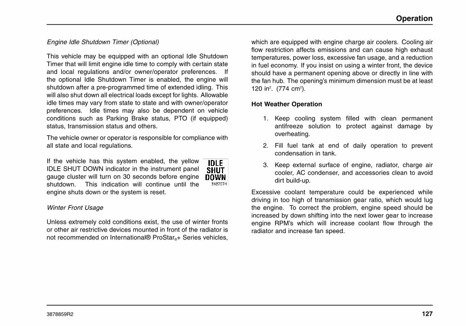
Operation
Engine Idle Shutdown Timer (Optional)
This vehicle may be equipped with an optional Idle ShutdownTimer that will limit engine idle time to comply with certain stateand local regulations and/or owner/operator preferences. Ifthe optional Idle Shutdown Timer is enabled, the engine willshutdown after a pre-programmed time of extended idling. Thiswill also shut down all electrical loads except for lights. Allowableidle times may vary from state to state and with owner/operatorpreferences. Idle times may also be dependent on vehicleconditions such as Parking Brake status, PTO (if equipped)status, transmission status and others.
The vehicle owner or operator is responsible for compliance withall state and local regulations.
If the vehicle has this system enabled, the yellowIDLE SHUT DOWN indicator in the instrument panelgauge cluster will turn on 30 seconds before engineshutdown. This indication will continue until theengine shuts down or the system is reset.
Winter Front Usage
Unless extremely cold conditions exist, the use of winter frontsor other air restrictive devices mounted in front of the radiator isnot recommended on International® ProStar®+ Series vehicles,
which are equipped with engine charge air coolers. Cooling airflow restriction affects emissions and can cause high exhausttemperatures, power loss, excessive fan usage, and a reductionin fuel economy. If you insist on using a winter front, the deviceshould have a permanent opening above or directly in line withthe fan hub. The opening’s minimum dimension must be at least120 in2. (774 cm2).
Hot Weather Operation
1. Keep cooling system filled with clean permanentantifreeze solution to protect against damage byoverheating.
2. Fill fuel tank at end of daily operation to preventcondensation in tank.
3. Keep external surface of engine, radiator, charge aircooler, AC condenser, and accessories clean to avoiddirt build-up.
Excessive coolant temperature could be experienced whiledriving in too high of transmission gear ratio, which would lugthe engine. To correct the problem, engine speed should beincreased by down shifting into the next lower gear to increaseengine RPM’s which will increase coolant flow through theradiator and increase fan speed.
3878859R2 127

Operation
Operating Instructions
General Information
WARNING
All vehicles have blind spots. Make sure yourway is clear in all directions before moving yourvehicle. Failure to follow these procedures couldresult in property damage, personal injury, ordeath.
WARNING
Operating an engine beyond the maximumgoverned speed could result in engine failureand cause vehicle damage, personal injury, ordeath.
Steering
Be alert to any change (feel) in steering when driving. Thischange or feel includes increased steering effort, unusualsounds when turning, excessive wheel play or pulling to eitherside. If any of the above are detected have the vehicle inspectedand repaired at once by a qualified mechanic.
WARNING
Do not adjust the steering column whilethe vehicle is moving. It could suddenly orunexpectedly move causing the driver to losecontrol of vehicle which could result in propertydamage, personal injury, or death.
CAUTION
Do not lubricate the tilt or telescoping steeringmechanism.
128 3878859R2

Operation
Adjustable Steering Column
1. Steering Wheel
2. Release Handle
If equipped with the optional tilting and telescoping steeringcolumn, the steering wheel can be adjusted as follows:
• Grasp the steering wheel with your right hand and unlockthe release handle with your left hand, by pushing forwardon the release handle.
• Using both hands, grab the sides of the steering wheel andadjust the telescoping feature to the desired position andthen the steering wheel tilt to the desired position.
• Hold the steering wheel in the newly acquired position withyour right hand and pull THE RELEASE HANDLE backwardtowards you, to the locked position, with your left hand.
• Make certain the steering wheel is in the proper position andthe column is locked.
General Information
• Start the vehicle in motion by utilizing the highest gear speedin the transmission that will enable the engine to easily pullthe load without slipping the clutch. Accelerate smoothly andevenly to engine rated speed. Rapid acceleration will resultin high fuel consumption.
• When approaching a hill, depress accelerator smoothly tostart the upgrade at full power, then shift down as needed tomaintain vehicle speed.
• Prevent over-speeding of the engine when going downlong and steep grades. The governor has no control overengine speed when it is being pushed by the loaded vehicle.Operate in a gear that will permit an engine speed belowthe Maximum Governed Speed or High-Idle RPM (no load).
3878859R2 129

Operation
Electrical
Alternator
CAUTION
Improper usage of fast charger, hook-up ofbooster battery or installing battery can causedamage to the electrical system or to thealternator.
Many alternators used in International® Truck vehicles are ofthe self-energizing type. Some engines may need to be brieflyrevved after starting to turn on the alternator. The alternator willthen charge at idle. If the vehicle is to be warmed up prior tobeginning operation, the operator should observe the voltmeterfor charging indication before leaving the vehicle.
Battery
WARNING
Keep lighted tobacco, flames, sparks or otherignition sources away from the batteries. Gasfrom the battery cells is flammable and canignite and/or explode. This is particularly truewhen jumper cables are being used. Batteryfires or explosions could cause personal injury,including severe injury to the face, eyes, limbsand body.
In addition, inhaling the hydrogen gas producedby the normal operation of the battery could resultin partial or permanent damage to the respiratorysystem which may result in death.
WARNING
Whenever disconnecting battery terminals,always disconnect ground terminal first. Whenreconnecting, always connect ground terminallast. Failure to follow this procedure could resultin a short to ground and cause property damage,personal injury, or death.
Always wear eye protection when workingaround batteries. Do not attempt to jump-start avehicle with a frozen battery because the batterymay rupture or explode. If a frozen battery issuspected, thaw out battery and recharge.
130 3878859R2

Operation
WARNING
DO NOT Check Battery Condition By Shorting(Flashing) Across Terminals. Failure to followthis warning could result in property damage,personal injury, or death.
When working around the terminals and battery, use extra careto avoid shorting. A good practice is to use insulated pliers andscrewdrivers.
BATTERY ON Indicator
1. Left Side of Dash
2. BATTERY ON Indicator
If the vehicle is equipped with a battery disconnect switch, anoptional BATTERY ON indicator may be located on the left side
of the instrument panel gauge cluster. The green BATTERY ONindicator will illuminate any time the battery disconnect switch isin the ON position (batteries connected) regardless of the keystate. This indicator can easily be viewed with the driver dooropen and without entering the vehicle.
Circuit Breakers, Fuses and Fusible Links
WARNING
Electrical circuits are designed with a particularwire gauge to meet the fuse and circuit breakercurrent rating. Do not increase size of fuse orcircuit breaker or change type of breaker suppliedwith your truck. To do so could cause wiring tooverheat and possibly burn, resulting in a firewhich could cause property damage, personalinjury, or death.
• Electrical circuits are protected either by the electricalsystem controller, circuit breakers, fuses or fusible links.For the size and location of circuit breakers, fuses andfusible links, please refer to the Maintenance Intervals andSpecifications section of this manual.
• Fusible links consist of a length of lighter gauge wire in acircuit. In case of a short or overload, the fusible link opens(burns out) to protect the remainder of the circuit. Repairconsists of installing a new fusible link with the same gaugewire as the opened fusible link.
3878859R2 131

Operation
• Circuit breakers interrupt the circuit when an overload orshort occurs. Manual circuit breakers (Type III) can be resetby depressing the reset button on the breaker. Headlampand wiper circuits are protected by the Body Controller.Type II circuit breakers will reset automatically if the short isremoved from the circuit.
• The various electrical units in the cab and enginecompartments are protected by either fuses or circuitbreakers. The power distribution center is located within theinstrument panel (glove box area) on the passenger side ofthe vehicle.
Electrical Load Control and Shedding (ELCS)
Electrical Load Control and Shedding (ELCS) is an optionalfeature (standard with sleepers) intended to provide a convenientmeans of automatically shutting down electrical loads overnightin order to conserve energy and deliver sufficient power to startthe engine. The system is active when the engine is not running,regardless of key state. The ELCS system does not includeprovisions for shutting down 120VAC circuits.
The ELCS will begin a sequence of events when the measuredbattery voltage is at or below 12.1VDC for a period of 30seconds. The sequence of events will first start with providingthe visual alert “Load Shedding” to the vehicle operator forat least 30 seconds. An audible alert, which consists of acontinuous tone, greater than 3 seconds and less than 6seconds in duration, will coincide with the start of the visualalert.
The audible alert can be disabled by a vehicle maintainer ifdesired. The sequence will then disable a predefined group
of features/electrical loads. These will remain disabled untilthe vehicle’s key switch transitions to the Accessory or ONpositions, and the measured voltage is above 12.1VDC.
Engine
The engine for this vehicle is an electronically controlled dieselengine. A separate ECM (electronic control module) monitorsand controls all engine functions. This ECM also communicateswith the body electrical system which will generate or activate thenecessary warning indicators to alert the driver of out-of-rangeoperating conditions.
For complete information on the engine in this vehicle and it’soptional features, refer to the Engine Operation and MaintenanceManual supplied with this vehicle.
NOTE: For information pertaining to fuel and requirements referto the Engine Operation and Maintenance Manual provided withthe vehicle.
Charge Air Cooler
All MaxxForce® engines are equipped with a charge air coolingsystem. The function of the charge air cooler is to cool the hotcompressed air before it enters the engine’s intake manifold.This system uses ambient air as the cooling medium by allowingthe intake air to pass through a network of heat exchangingfins and tubes prior to entering the combustion chamber. Theresulting cooler intake air is denser than uncooled air and willallow additional fuel to be injected for greater power while helpingto reduce emissions.
132 3878859R2

Operation
Electronic Engine Controller
Each vehicle contains an Engine Operation and MaintenanceManual in the driver’s door pocket. Refer to the EngineOperation and Maintenance Manual for detailed information onthese engine control systems.
Engine Brake
WARNING
Do not use the engine brake on slippery roadsurfaces. Doing so may cause wheel slippageand/or loss of vehicle control, which could resultin property damage, personal injury, or death.
NOTE: The engine brake should never be considered asubstitute for the vehicle service brakes. The service brakesshould always be viewed as the primary vehicle braking system.The engine brake cannot bring the vehicle to a complete stop.Only the service brakes can bring the vehicle to a complete stop.
All of the optional braking features are controlled by the driver,using the ENGINE BRAKE ON/OFF switch on the steeringwheel and the ENGINE BRAKE 1/2/3 power level selectorswitch located in the Center Control Switch Panel.
To activate the engine brake, press the push buttonENG BRAKE ON/OFF switch on the steering wheel(pressing this switch again will deactivate the system).The ENGINE BRAKE SELECTOR 1/2/3 switch is thenused to adjust the amount of braking applied.
Using engine braking features can extend brake lining life. Thefeatures also allow the driver to slow the vehicle down or maintaina constant speed on steep road grades that would otherwiseresult in prolonged use of the service brake that could causebrake fade. Refer to the Engine Operation and MaintenanceManual for detailed information on the engine braking system.
MaxxForce® 11, 13 and 15 Engine Brake With EatonAutoShift®/UltraShift® Transmissions Special DriverInstructions
Low or manual transmission mode can be used to maximizeengine brake performance.
• Keep engine speed as close to 2250 rpm as possible.
• Maintain brake pedal application until any desired downshiftsare completed. Failure to do so may cause missed shifts.
• The gear display on the shift selector will stop blinkingwhen the downshift is completed, and the driver will noticeresumption of engine braking as an indication that the shiftis completed.
When the transmission is in manual mode, engine protectionupshifts are disabled. This could result in an undesirable engineoverspeed condition. It is the operator’s responsibility to prevent
3878859R2 133

Operation
mechanical damage to the truck. Under these conditions, useservice brakes and select the appropriate gear, as required, tokeep the engine rpm within operating limits.
MaxxForce® Engine Features
The MaxxForce® engines are electronically controlled dieselengines. The engine Electronic Control Module (ECM) monitorsand controls the injection process and other engine functions.The ECM also communicates with the Body Controller (BC)and alerts it to out-of-range operating conditions. The BCin turn, generates engine function indicators and warningindicators. Since many of the engine performance features areowner selectable and electronically programmable, some of theoperating parameters will vary from vehicle to vehicle. Someof these standard and optional monitored engine operatingfunctions and warning indicators include:
Some standard features:
• Engine Warm-Up Control - (ECM) adjust injector operationas required.
• Cold Ambient Protection (CAP) - to aid engine warm up andmaintain engine temperature.
• Cruise Control - provides vehicle speed control.
Some Optional Features:
• Engine Warning System - this system illuminates the Red“Engine” indicator and actuates a beeper when warningthresholds for coolant temperature, engine coolant level,and/or low engine oil pressure are exceeded.
• Engine Shutdown System - this system shuts downthe engine after 30 seconds of operation beyond criticalthreshold values for coolant temperature and/or oil pressure.
• Throttle Control for PTO Operation.
• Road Speed Limiting/Governor - programmable maximumspeed.
• Idle Shutdown Timer - shuts down engine after 5 minutes ofidle time.
Certified Clean Idle
MaxxForce® 11, 13 and 15 engines have been designed to meetthe new California Air Resources Board (CARB) idle reductionstandards by generating less than 30-g/hr. NOx emissions whenidling. These engines can be identified by the Certified CleanIdle decal located on the left side of the hood or driver door.
Self Diagnostics
All MaxxForce® engine operating parameter Warning Indicatorsare located on the instrument panel gauge cluster. When theignition switch is turned ON, the Engine Warning Indicators areilluminated and remain on while the ECM runs normal start-uptests, then goes OFF. If warning indicator stays on or comes onwhile operating the vehicle, it is an indication that the vehicleneeds service. When the warning indicator is illuminated, aDiagnostic Trouble Code (DTC) will be generated. Take thevehicle to a service center as soon as possible as some optionalfeatures and or engine power may be lost while the indicator islit.
134 3878859R2

Operation
Air Compressor Cycling
The MaxxForce® 11, 13 and 15 liter engines can be equippedwith one of two different types of air compressor and may haveone or two cylinders.
• Head Unloaded Air Compressor: This single cylinder,constantly engaged air compressor works in conjunctionwith the air governor and air dryer to pump compressed airto the air dryer and air tanks. When additional compressedair is not needed air is shut off from the air compressordischarge line and confined to the air compressor cylinderand its head.
• Clutched Air Compressor: This high-capacity, twocylinder, air compressor is periodically engaged by usingan on-off clutch. It works in conjunction with air governorand air dryer to pump air to the air dryer and air tanks.When additional compressed air is not needed, the clutchis disengaged, compressor speed goes to zero, and allair pumping ceases. This system provides relatively lowcylinder temperatures and sound verses other compressorsduring the unloaded cycle. It is used to promote maximumfuel economy by eliminating pumping energy loss duringthe unloaded cycle.
As the compressor reaches approximately 130 psi (896 kPa),the air governor will, through various methods, stop the aircompressor from pumping pressurized air to the air system.When the air pressure reaches approximately 110 psi (758kPa), the governor signals the air compressor to resumepumping pressurized air to the air system. During normal
engine operation, this cycle will be evident by the fluctuation ofthe primary air tank pressure gauge.
Cooling System
WARNING
To prevent personal injury or death fromhot coolant or steam, use only the followingprocedure to remove the pressure cap from theradiator or expansion tank. Allow the engine tocool first. Wrap a thick, heavy cloth around thecap. Unscrew the cap slowly to allow pressureto release from under the cap. After the pressurehas been released, the pressure cap may beremoved.
WARNING
Exercise great care when working on vehicleswith running engines that are equipped withan automatic fan clutch. The fan engageswhen engine coolant reaches a predeterminedtemperature or the refrigerant pressure (ifequipped with air conditioning) reaches apredetermined setting. The fan will start withno advance warning. Failure to observe theseprecautions could result in vehicle damage,personal injury or death.
3878859R2 135
Operation
CAUTION
If the coolant should get extremely low andthe engine very hot, let the engine cool forapproximately 15 minutes before adding coolant;then, with the engine running, add coolant slowly.Adding cold coolant to a hot engine may crackthe cylinder head or crankcase. Never use wateralone.
The cooling system in vehicles with MaxxForce® 11, 13 and 15engines, is filled at the factory with Nitrite-free Shell Rotella®Ultra ELC (Yellow) coolant. International Truck recommendsusing only the approved coolant with the 2010 cooling packages,and will not warrant these cooling systems that have not utilizedthe recommended coolant.
The label on the deaeration tank provides additionalcoolant/antifreeze information. Consult the Engine Operationand Maintenance Manual for coolant service life details.
Engine Oil
Keep oil level between the ADD and Full marks. Never operatean engine with oil level below the ADD mark.
To obtain an accurate engine oil level reading the vehicle mustbe parked on a level surface with the engine off for at least fiveminutes before checking the oil level. This will ensure the oilis level in the oil pan, and the circulated oil has had a chance toreturn to the pan. It is not necessary for the oil to be hot to obtainan accurate reading.
When checking the oil level, the dipstick must be withdrawn andwiped clean, then inserted all the way and again withdrawn for atrue check.
Use only recommended viscosity engine oil. Refer to the EngineOperation and Maintenance Manual for engine oil specifications.
The lubricating oil in a diesel engine becomes dark in colorafter short periods of engine operation. This discoloration is notharmful to engine parts as long as the oil and oil filter elementchanges are performed at recommended intervals.
All International® ProStar®+ Series vehicles must use CJ-4or later oil classifications to achieve maximum DPF cleaningintervals.
Refer to the appropriate Engine Operation and MaintenanceManual for proper oil viscosity choice.
Engine Performance Problems
• Low engine power can be the result of a plugged fuel filter.Fuel filters can plug prematurely due to the use of fuel thatis contaminated with a high amount of sediment, microbialgrowth, or water. Fuel that has been stored for longerperiods of time may also reduce engine performance.
• Failure to maintain the vehicle as required in theMaintenance Instructions and Maintenance Intervalsand Specifications sections of this manual, as well as anyseparately available Engine Operation and MaintenanceManual, can cause engine performance problems.
Too low of cetane number could cause hard starting andslower warmup and could increase engine noise and exhaustemissions.
136 3878859R2
Operation
Fuel
Ultra Low Sulfur Diesel Fuel Requirements
Ultra Low Sulfur Diesel (ULSD) fuel is required for all on-highwaydiesel engines used with advanced after-treatment systems(Diesel Particulate Filters – DPF). For complete details on fuelrequirements, see the Engine Operation and MaintenanceManual supplied with the vehicle.
Unacceptable Fuel Blends
Biodiesel blends having more than 5 percent pure biodiesel arenot within ASTM D975 diesel specifications.
To determine acceptable biodiesel and biodiesel blends, refer tothe Engine Operator and Maintenance Manual for the applicableengine.
Hazards of Diesel Fuel/Gasoline Blends
WARNING
Never add gasoline, gasohol and/or alcohol todiesel fuel. This mixture creates an extremefire and explosion hazard which could result inproperty damage, personal injury, or death.
Blending of gasoline and/or alcohol with diesel fuel is notrecommended due to the hazards of fire/explosion and thedetrimental effects on engine performance.
As little as two percent volume gasoline mixed with diesel fuelwill create a flammable/explosive mixture in the fuel tank vapor
space, which will pose an extreme fire/explosion hazard duringrefueling or engine operation.
Additional Unsafe Practices
CAUTION
To prevent engine damage, do not mix propanewith diesel fuel. Warranty claims will not behonored against engines that have used propane.
CAUTION
To prevent engine damage, do not mix engineoil with diesel fuel. Warranty claims will not behonored against engines that have used fuelmixed with oil.
Fuel and Lubricant Additives
International trucks are designed and built to operatesatisfactorily on fuels and lubricants of good quality marketedby the petroleum industry. Use of any supplementary fuel orlubricant additives is not recommended. Malfunctions attributedto the use of such additives or failure to follow recommendedfuel or lubricant recommendations may not be covered by anyapplicable warranty.
Fueling Procedures
NOTE: If your vehicle is equipped with dual fuel tanks, be sureto read and understand the following information before refuelingthe vehicle.
3878859R2 137
Operation
Dual tank systems are equipped with dual draw and dual returnfuel line systems to equalize the fuel temperature and levelbetween the dual tanks.
When refueling, be sure that both tanks are filled completely, asboth tanks cannot be filled from one side.
Fueling Precautions
Federal Motor Carrier Safety Regulations require the driveror any employee of a motor carrier to observe the followingrequirements:
1. Do not fuel a motor vehicle with the engine running,except when it is necessary to run the engine to fuel thevehicle.
2. Do not smoke or expose any open flame in the vicinityof a vehicle being fueled.
3. Do not fuel a motor vehicle unless the nozzle of the fuelhose is continuously in contact with the intake pipe ofthe fuel tank.
4. Do not permit any other person to engage in suchactivities as would be likely to result in fire or explosion.
Reserve Fuel
No extra supply of fuel for the propulsion of the vehicle or for theoperation of accessories shall be carried on any motor vehicle,except in a properly mounted fuel tank or tanks.
138 3878859R2

Operation
Exhaust Diesel Particulate Filter Regeneration
This vehicle is equipped with a Diesel Particulate Filter(DPF) to meet 2010 emissions requirements. The DPF trapsexhaust particulate matter generated by normal engine usage.Periodically, the engine control system will perform a “cleaning”of the filter, known as Normal Regeneration. This process istransparent to the operator and occurs during normal vehicleoperation.
In some cases the engine control system is unable to managesoot levels in the DPF through Normal Regeneration. Whenthis occurs the DPF indicator will illuminate solid YELLOW onthe instrument panel gauge cluster advising that action must betaken. At this time the vehicle should then be driven at highwayspeeds, or pulled over to perform a Parked Regeneration (SeeParked Regeneration Procedure). If no action is taken theDPF indicator will begin to flash indicating that the filter is full.The vehicle should then be pulled safely off the roadway anda Parked Regeneration should be performed. If the vehicle isdriven beyond the initial two warning stages, a loss of engineperformance (de-rate) will occur. Ignoring the need for aParked Regeneration, when required, can result in a warning forexcessive exhaust temperatures, and a requirement to shut theengine off and not restart it until the DPF has been serviced bya technician. It is important to perform a Parked Regenerationwhen required. Failure to do so could be mission disabling andresult in the vehicle being towed.
See the following information for a detailed explanation of DPFindicators and the corresponding procedures that must befollowed.
WARNING
Failure to perform a Parked Regeneration whenexhaust filter indicator is ON will cause the engineto lose power and eventually shutdown.
When performing Parked Regeneration, makecertain vehicle is safely off of the roadwayand exhaust pipe is away from people, or anyflammable materials or structures.
Failure to follow these instructions may result ina loss of engine power, vehicle speed, increasedexhaust temperatures, and may cause anaccident or fire resulting in property damage,personal injury, or death.
There will be three levels of indication that the vehicle’s exhaustfilter is accumulating soot and needs to be cleaned, each withan increasing urgency for action.
NOTE: A Level 1 indication may disappear or a Level 2 mayrevert to a Level 1, if the vehicle is driven on highway athighway speeds for an extended period. This process of autoregeneration of the exhaust filter is activated when the engineload is increased as a result of highway driving at highwayspeeds. If the DPF indicator does not reduce in level ordisappear, a Parked Regeneration must be performed.
NOTE: The following table is a typical representation of 2010DPF emissions procedures (See visor for vehicle federalemissions label).
3878859R2 139

Operation
2010 Federal Emissions Label
Level Indication Audible Alarm LCD Text MessageVehicle
Conditions/OperationAction Required
1
(Solid)
None
Scrolls betweenSee Visor for infoand Parked RegenRequired.
Exhaust filterregeneration required.
Drive on highway at highway speeds or start ParkedRegeneration to prevent loss of power.
2
(Flashing)
None
Scrolls betweenSee Visor for infoand Parked RegenRequired.
Exhaust filter is full.Pull vehicle safely off roadway and start ParkedRegeneration to prevent loss of engine power.
3
(Flashing)
An alarm will beepcontinuously whileignition is on.
Scrolls betweenSee Visor for infoand Parked RegenRequired.
Exhaust filter is full.Engine performance isLIMITED.
WARNING
Pull vehicle safely off roadway andstart Parked Regeneration to preventengine stopping.
Exhaust System Temperature is HOT
WARNING
Exhaust components are operating under normal conditions and exhaust gases are at extremely high temperatures.When stationary, keep away from people and flammable materials, vapors, or structures or STOP ENGINE
A serious problem has occurred. Engine may SHUTDOWN soon. Pull vehicle safely of roadway, turn on flashers, set parking brake, placewarning devices, and STOP ENGINE. Seek service immediately.
140 3878859R2

Operation
Parked Regeneration Procedure
Perform the following steps to initiate Parked Regeneration(cleaning) of the exhaust filter:
1. Park the vehicle safely off the roadway and away fromflammable materials.
2. Before initiating parked regeneration (using the ON/PARKDREGEN switch), the following conditions must be in place:
a. Parking brake must be set
b. DPF indicator illuminated (Solid or Flashing).
c. Transmission must be in Neutral (N) or Park (P), ifavailable
d. Accelerator, foot brake and clutch (if present) pedalsmust not be depressed,
e. Engine temperature must be at a sufficient level to allowregeneration.
With some engines, this may be as high as 76.6° C (170°F).
NOTE: The engine coolant temperature must be above 76.6°C (170° F) before the parked regeneration procedure can beperformed. If the engine coolant temperature is too low, theparked regeneration procedure will not activate.
3. Press the ON position of the ON/PARKD REGEN switch toinitiate the regeneration cycle.
The engine speed will automatically ramp up to a presetRPM, PARKD REGEN ACTIVE will be displayed in the
information display, and the switch indicator will illuminatewhen the cycle is started. If the indicator is blinking, checkto be sure that all conditions in step 2 have been met. Oncestarted, the regeneration cycle will last approximately 30minutes.
NOTE: If any of the above conditions are altered during theParked Regeneration process, regeneration will be halted, andmust be restarted.4. When the regeneration cycle is complete, the
switch indicator will go off, the engine rpm willreturn to normal idle and all exhaust filter warningindicators will be off. The vehicle may now bedriven normally.
NOTE: In the event of an emergency situation where the vehiclemust be moved after beginning Parked Regeneration, pressPARKD REGEN position of the ON/PARKD REGEN switch tocancel Parked Regeneration.
Regeneration Inhibit Switch
The optional Regeneration Inhibit switch is usedto prevent the normal regeneration or parkedregeneration processes.
NOTE: There are two versions of the regenerationinhibit switch: the two-position and the three-positionswitch. Therefore, it’s necessary to verify which version isinstalled in this vehicle. Both versions have the same switchlabels.
3878859R2 141

Operation
Two-Position Regeneration Inhibit Switch
With the optional two-position switch, pressing the ON positionof the ON/INHIBT REGEN switch will inhibit both normal andparked regeneration. Regeneration will be inhibited (latched)when in this position and the switch indicator is turned on.
Three-Position Regeneration Inhibit Switch
The optional three-position switch is a center stable momentaryswitch. Pressing the ON position inhibits normal regenerationwhile the engine is running and is reset when the ignition switchis turned off. The Inhibit function is cancelled when the lowerposition is pressed, or parked regeneration is initiated (PARKDREGEN switch is turned to the ON position).
The switch indicator will be turned on whenever regenerationinhibit is enabled.
Transmission
Manual Transmissions
Vehicles with a manual or AutoShift transmissions have a clutchpedal that is used to engage or disengage the clutch, connectingor disconnecting the engine from the transmission and rearwheels. With the clutch pedal released (extended) the clutch isengaged, driving the transmission and rear wheels. Depressingthe clutch pedal releases the clutch, permitting transmissiongear changes.
Clutches will last many thousands of miles if properly used andmaintained. EXCESS HEAT IS A CLUTCH’S WORST ENEMY!
Almost every early clutch failure can be traced to excessivefriction heat. Do not ride or slip the clutch. Once a clutch isfully engaged, there is no heat generated and little or no wear.However, during the brief period when the clutch is picking upthe load, considerable heat is generated. By riding or slippingthe clutch, the period of partial engagement is lengthened,causing unnecessary heat and wear and reduced clutch life.
The International® ProStar®+ Series has many transmissionoptions available. Refer to the Transmission Manual forinformation on the transmission available in your truck.
1. HighRange
2. LowRange
10-Speed Manual Transmission (standard): The gear shiftlever mechanically engages and disengages five forward gearsand one reverse gear in the transmission front section. Therange lever on the Roadranger Valve allows the operator tocontrol an air shifted auxiliary section to provide a LO range andHI range. The five forward gear shift positions selected in LOrange are used again in HI range to provide the 10 progressive
142 3878859R2

Operation
forward gear ratios. Once the highest shift lever position (5thgear) is obtained in LO range, the operator preselects the rangeshift lever for HI range. The range shift occurs automatically asthe shift lever is moved from 5th gear position to the 6th gearposition.
1. When operating off-highway, or under adverseconditions, always use the lowest gear when starting tomove the vehicle.
2. For all normal conditions, use the highest gear that isstill low enough to start the vehicle moving with engineidling, and without slipping the clutch excessively.
3. Use the clutch brake to stop gear rotation when shiftinginto low (or 1st) or reverse when the vehicle is stationary.The clutch brake is actuated by depressing the clutchpedal all the way to the floor.
4. Do not make range shifts with the vehicle moving inreverse gear.
5. Never attempt to move the range preselection lever withthe gear shift lever in neutral while the vehicle is moving.Preselection with the range preselection lever must bemade prior to moving the shift lever out of gear intoneutral.
6. Do not shift from high range to low range at high vehiclespeeds.
7. Double-clutch between all upshifts and downshifts.
8. After your shifting ability improves, you may want toskip some of the ratios. This may be done only whenoperating conditions permit, depending on the load,grade, and road speed. Transmissions with a greaternumber of speeds are optionally available. They mayinclude the use of a splitter selector switch in additionto the range selector switch.
Engaging the Clutch
• Always start in the proper gear: An empty vehicle canbe started in a higher gear than a fully loaded one. Butstarting in a gear too high for the load can cause too muchclutch slippage, generating excessive heat and unnecessarywear. A gear that will start the vehicle moving with theengine at idle speed is usually correct. If the engine mustbe revved up to prevent stalling, the gear selection is toohigh. As the clutch pedal is released and the clutch beginsto engage, the engine speed will drop slightly. When thishappens, fully engage the clutch and increase the enginespeed. Increasing the engine speed before fully engagingthe clutch can damage the clutch and drivetrain.
• Do not upshift until the engine has reached properspeed. Upshifting before the vehicle has reached the rightspeed will lug the engine.
• When approaching a hill, depress accelerator smoothly tostart the upgrade at full power, then downshift as needed tomaintain vehicle speed.
3878859R2 143
Operation
• Never hold a vehicle on a hill with the clutch. To holdon a hill with the clutch requires that the clutch be purposelyslipped. By doing this enough heat can be generated to burnup the clutch.
• Never coast with the clutch disengaged. This cancause clutch failure by the very high RPM encounteredwhen coasting in gear with the clutch released. In thissituation, the rear wheels are driving the disc through themultiplication of the rear axle and transmission ratios. Thiscan result in over 10,000 RPM, which is beyond the burststrength of the facing material. Something as simple ascoasting down an unloading ramp can burst a driven disc.
Re-engaging a clutch after coasting causes tremendousshock to the clutch and the whole drivetrain. It can result ininternal engine damage and/or clutch and flywheel failure.Always report unusual clutch operation promptly. Propermaintenance, performed on time, will greatly extend the lifeof the clutch. The driver should report any change in freepedal (free travel) slippage or any strange feel to the clutchoperation.
Helpful Hints to Operate Vehicles with Ceramic ClutchFacings
1. Driver must start vehicle in first (low) gear.
2. While operating a ceramic clutch the driver has toengage the clutch before giving the engine any fuel (atidle).
3. The driver should not try to slip the ceramic clutchby raising engine RPM’s and riding or featheringclutch pedal since the vehicle will experience erraticengagement.
Erratic engagement can cause engine stalling and potentialserious damage to your vehicle’s drivetrain components (i.e.,clutch, transmission, driveshaft(s), rear axle).
Hydraulic Clutch Actuation System
Clutch brake engagement occurs in the last 2 inches (50 mm)of pedal travel after initial clutch setup adjustment. Clutch wearwill move the pedal position at clutch brake engagement towardthe physical limit of travel. The hydraulic clutch system musthave proper fluid bleeding before operating, usually performedat the factory, or at field servicing. Hydraulic clutch fluid shouldbe drained and refilled every 2 years of service or after 200,000miles (322,000 km) service interval.
CAUTION
To prevent vehicle or engine component damage,clutch pedal must engage clutch brake before thephysical limit of pedal travel. When the clutchpedal position at clutch brake engagement is lessthan 0.5 inch (12.7 mm) from the physical travellimit, manual clutch adjustment is required for allEaton® Easy Pedal® (EP) clutches.
If non-self adjusting clutches are used in this application, it isimportant that clutch adjustments be maintained. Adjustmentintervals should be every 20,000 miles (32,000 km). Whenutilizing an Eaton® EP clutch with a hydraulic clutch actuator,
144 3878859R2

Operation
the cab clutch pedal cannot be used to indicate when clutchadjustment is required. Drivers may not notice the need forclutch adjustment and continue to drive in such condition. Lackof adjustment will eventually lead to yoke interference withthe clutch cover causing extensive clutch and or transmissiondamage.
When using the clutch brake, fully depress the clutch pedaland shift the transmission into either first or reverse gear. If thetransmission does not go into first gear or reverse, toothbuttingmay be occurring. Slowly release the clutch pedal while applyinglight pressure on the shift lever until the transmission goes intogear. This will provide for a smooth shift into either a forward orreverse gear.
NOTE: After engagement of first gear, DO NOT use the clutchbrake for upshifting and downshifting. To do so will shorten theservice life of the clutch brake, and gear selection shift effortsmay be increased. Clutch brake application occurs in the last 2inches (50 mm) of pedal travel.
Double Clutch Procedures
In order to properly upshift or downshift, be sure to do thefollowing:
• Depress the clutch pedal to disengage the clutch.
• Shift the transmission into neutral.
• Release the clutch pedal.
• If upshifting, wait until the engine speed matches thetransmission speed of the gear you desire to shift into.
• If downshifting, accelerate the engine until the engine speedmatches the input speed of the gear you desire to shift into.
• Depress the clutch pedal immediately and shift into thedesired gear.
• Release the clutch pedal to engage the clutch.
Clutch Precautions
Maintain specified clutch adjustment. Regularly inspect clutchcontrol linkage for tightness.
When adjustment of the clutch is necessary, it is extremelyimportant that the work be properly performed; otherwise, earlyfailure of the clutch will result and a costly clutch overhaul willbe necessary.
To avoid needless delay and expense, allow only competent andexperienced mechanics to perform these operations.
3878859R2 145

Operation
Eaton AutoShift® Transmissions (Optional)
WARNING
To prevent unexpected vehicle movement, holdthe brake pedal down while you move thegearshift from position to position. Hold downboth brake and clutch pedal while pushing the“R” and “D” button. If you do not hold the brakepedal down, your vehicle may move unexpectedlyand cause property damage, personal injury, ordeath.
The optional Eaton AutoShift® transmission is a partiallyautomatic transmission that automatically selects and engagesthe proper transmission gears. Vehicles are equipped with aclutch pedal that must be used when starting and stopping thevehicle.
To shift the Eaton transmission into Reverse (R) or Drive (D),first place foot on the brake and clutch pedal. When in Drive(D), the transmission selects the starting gear and automaticallyselects the proper gears for operating loads. If low (L) isselected while the vehicle is stopped, the transmission willremain in low gear until another gear is selected. If selectedwhile in motion, the transmission will downshift when it is safeto do so. To place the transmission in neutral, press the (N)button. Manual mode should be used whenever the driver wantsto select the shifts instead of letting AutoShift® transmissionselect them automatically. For operating instructions refer to theTransmission Manual.
The current gear selection and other information is alsodisplayed on the instrument panel gauge cluster display.
146 3878859R2
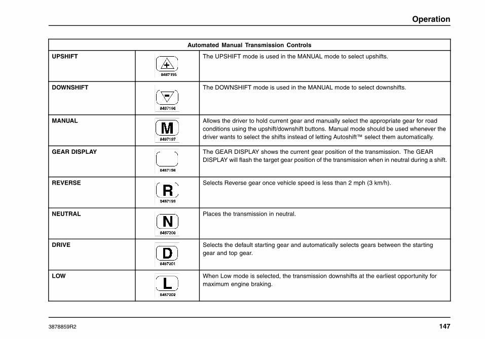
Operation
Automated Manual Transmission Controls
UPSHIFT The UPSHIFT mode is used in the MANUAL mode to select upshifts.
DOWNSHIFT The DOWNSHIFT mode is used in the MANUAL mode to select downshifts.
MANUAL Allows the driver to hold current gear and manually select the appropriate gear for roadconditions using the upshift/downshift buttons. Manual mode should be used whenever thedriver wants to select the shifts instead of letting Autoshift™ select them automatically.
GEAR DISPLAY The GEAR DISPLAY shows the current gear position of the transmission. The GEARDISPLAY will flash the target gear position of the transmission when in neutral during a shift.
REVERSE Selects Reverse gear once vehicle speed is less than 2 mph (3 km/h).
NEUTRAL Places the transmission in neutral.
DRIVE Selects the default starting gear and automatically selects gears between the startinggear and top gear.
LOW When Low mode is selected, the transmission downshifts at the earliest opportunity formaximum engine braking.
3878859R2 147

Operation
Eaton UltraShift® Transmissions (Optional)
The optional Eaton UltraShift® transmission is an automatictransmission that can automatically select and engage theproper transmission gears. Vehicles equipped with thistransmission do not have a clutch pedal. For operatinginstructions refer to the Transmission Manual.
Clutch Brake
NOTE: After engagement of first gear DO NOT use the clutchbrake for upshifting and downshifting. To do so will shorten theservice life of the clutch brake and gear selection shift effortsmay be increased.
A clutch brake is used to stop transmission input shaft rotation sothat the initial first or reverse gear selection can be accomplishedwhen the vehicle is at a standstill and the engine is running atidle speed.
When using the clutch brake, fully depress the clutch pedaland shift the transmission into either first or reverse gear. Ifthe transmission does not go into first gear or reverse, toothbutting may be occurring. Slowly release the clutch pedal whileapplying light pressure on the shift lever until the transmissiongoes into gear. This will provide for a smooth shift into eitherfirst or reverse gear.
Power Take-off Control
If your vehicle is equipped with a power take-off (PTO), refer tothe PTO equipment manufacturer’s instructions.
Rear Axles
Locking or Limited Slip Differentials
WARNING
To prevent vehicle damage, personal injury, ordeath, pay strict attention to the following:
If your vehicle is equipped with any type oflocking or limited slip differential, power will betransmitted to the opposite wheel should one ofthe wheels slip. Both wheels must be raised freeof the ground should it be necessary to operateone wheel with the vehicle stationary; otherwisethe wheel that is not raised will pull the vehicleoff its support, possibly resulting in personalinjury or death.
WARNING
To prevent vehicle damage, personal injury, ordeath, pay strict attention to the following:
Care should be taken to prevent suddenaccelerations when both drive wheels are ona slippery surface. This could cause both drivewheels to spin, and allow the vehicle to slidesideways, resulting in loss of vehicle control.
148 3878859R2

Operation
Tandem Axle Power Divider Lock (PDL) Control
CAUTION
Do not operate the vehicle with the PDL engagedon dry pavement (good traction) continuously.This will result in excessive tire wear andpremature axle wear.
Never engage the PDL when the wheels arespinning.
The PDL should be engaged, which prevents inter-axledifferential action, when backing under a trailer with a tractor,starting on a slippery surface (poor traction), operating offhighway in mud, etc. (poor traction), or when traveling onslippery highways (poor traction). Failure to lock the powerdivider under these conditions may result in power dividerfailures and costly repairs. If you encounter wheel spinconditions, the PDL switch should be moved to the LOCKposition.
CAUTION
Engage the PDL only when stopped or moving atlow speed. Never try to engage the PDL while thewheels are spinning as this may result in shockdamage to the power divider components.
When encountering slippery highway conditions (poor traction),the PDL can be engaged at a low, even speed. Momentarily
letting off the accelerator will engage the differential lock. Awarning indicator on the instrument panel indicates when theinter-axle differential is locked.
When highway conditions improve (good traction), the PDLshould be disengaged, again at a low, even speed. Lettingup on the accelerator momentarily will unlock the inter-axledifferential.
Tandem axle power dividers or inter-axle differentialsin the forward rear axle are controlled by the dashmounted Power Divider Lock (PDL LOCK) switch.
The switch indicator will turn on when the PDL isengaged (locked). The vehicle may be electronicallyprogrammed to provide an alarm when a speed isreached where it is not appropriate to have the powerdivider locked. In this event, an alarm will sound (5 beeps) andthe switch indicator will flash slowly (once per second). A fastflashing (twice per second) switch indicator signifies a problemin the PDL system.
Under normal highway conditions (good traction), the PDLshould be disengaged, which allows differential action betweenthe forward rear axle and the back rear axle preventing inter-axledifferential wear due to unequally worn or mismatched tires, etc.
3878859R2 149
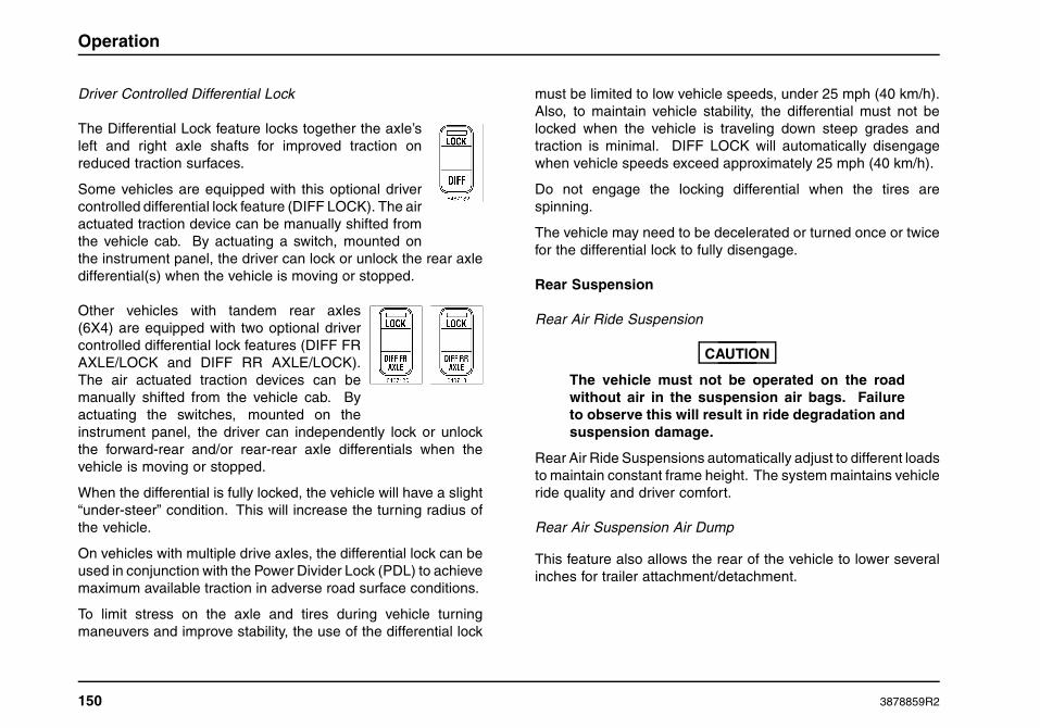
Operation
Driver Controlled Differential Lock
The Differential Lock feature locks together the axle’sleft and right axle shafts for improved traction onreduced traction surfaces.
Some vehicles are equipped with this optional drivercontrolled differential lock feature (DIFF LOCK). The airactuated traction device can be manually shifted fromthe vehicle cab. By actuating a switch, mounted onthe instrument panel, the driver can lock or unlock the rear axledifferential(s) when the vehicle is moving or stopped.
Other vehicles with tandem rear axles(6X4) are equipped with two optional drivercontrolled differential lock features (DIFF FRAXLE/LOCK and DIFF RR AXLE/LOCK).The air actuated traction devices can bemanually shifted from the vehicle cab. Byactuating the switches, mounted on theinstrument panel, the driver can independently lock or unlockthe forward-rear and/or rear-rear axle differentials when thevehicle is moving or stopped.
When the differential is fully locked, the vehicle will have a slight“under-steer” condition. This will increase the turning radius ofthe vehicle.
On vehicles with multiple drive axles, the differential lock can beused in conjunction with the Power Divider Lock (PDL) to achievemaximum available traction in adverse road surface conditions.
To limit stress on the axle and tires during vehicle turningmaneuvers and improve stability, the use of the differential lock
must be limited to low vehicle speeds, under 25 mph (40 km/h).Also, to maintain vehicle stability, the differential must not belocked when the vehicle is traveling down steep grades andtraction is minimal. DIFF LOCK will automatically disengagewhen vehicle speeds exceed approximately 25 mph (40 km/h).
Do not engage the locking differential when the tires arespinning.
The vehicle may need to be decelerated or turned once or twicefor the differential lock to fully disengage.
Rear Suspension
Rear Air Ride Suspension
CAUTION
The vehicle must not be operated on the roadwithout air in the suspension air bags. Failureto observe this will result in ride degradation andsuspension damage.
Rear Air Ride Suspensions automatically adjust to different loadsto maintain constant frame height. The system maintains vehicleride quality and driver comfort.
Rear Air Suspension Air Dump
This feature also allows the rear of the vehicle to lower severalinches for trailer attachment/detachment.
150 3878859R2

Operation
The system is controlled by the two positionSUSP/DUMP switch with an indicator light in theDUMP position. This switch controls solenoids, whichdirect air to the suspension dump and height valve.
When the SUSP/DUMP switch is in the DUMP positionand the vehicle speed is below 5 mph (8 km/h), airsupplied to the rear air suspension is released,lowering the frame for loading.
Placing the switch in the SUSP position causes air to fill or remainin the air suspension for proper operating ride height.
The SUSP/DUMP switch will operate the IROS system onlyif the ignition switch is in either ACC or ON positions and theair tanks have sufficient pressure to fill the suspension. Whenthe ignition switch is turned off, power to the solenoid will beremoved, therefore, the suspension will remain in the state lastset by the SUSP/DUMP switch.
NOTE: The suspension will dump when the ignition switch is inthe either ACC or ON position, but will only fill when the ignitionswitch is in the ON position.
NOTE: The SUSP/DUMP switch functions will be inhibitedby either a Traction Control or ABS event. In either event foreither SUSP or DUMP operation, the ASD switch will have tobe manually recycled after the event has passed in order tocomplete the operation.
NOTE: The electrical system will automatically switch fromDUMP to SUSP if the vehicle speed exceeds 5 mph (8 km/h).Once this occurs, the only means to deflate the suspension willbe to slow the vehicle to 5 mph, and recycle the SUSP/DUMPswitch to the DUMP position.
Air Suspension System Faults
• The instrument panel gauge cluster will issue an audible 10beep alarm whenever the driver pushes the DUMP positionof the SUSP/DUMP switch, and the vehicle exceeds 5 mph(8 km/h).
• The SUSP/DUMP switch indicator will blink rapidly in theevent of a system component failure or a bad system signalstatus, when the SUSP/DUMP switch is in the DUMPposition.
• The SUSP/DUMP switch indicator will blink slowly in theevent of an ESC command fault, regardless of the positionof the SUSP/DUMP switch.
Brakes
General Information
WARNING
Always check and maintain brakes in propercondition and adjustment. Out of adjustmentbrakes could cause reduced braking ability andresult in property damage, personal injury, ordeath.
3878859R2 151
Operation
Downhill Operation
WARNING
Do not attempt to gear down if the engine isat or near maximum speed (RPM). Under theseconditions it will be impossible to shift into alower gear and could result in possible vehiclerunaway, resulting in property damage, personalinjury, or death.
Always descend hills with extreme care, relying primarily on theengine braking effect to control vehicle speed. Heed warningsigns posted for any grade. Stop and check brakes for conditionand adjustment at available pull off areas before starting adescent.
Observe the following precautions:
• Never coast downhill. Service brakes alone should not beused to control speed on major downgrades. Brakes willfade from overuse.
• Downhill speed is controlled by removing one’s foot from theaccelerator pedal (engine running with closed throttle) andputting the transmission/rear axle in reduced gear. If thetransmission/rear axle is in a gear that results in more thanthe appropriate speed, a proper downshift should be madeto avoid overuse of the brakes. If the proper gear selectionwas not made and the brakes were overused, then stop thevehicle and wait for the brakes to cool. After the brakes havecooled, continue down grade in a lower gear range.
• The common rule to follow in using the engine andtransmission/rear axle to control vehicle speed is to selecta lower gear going down the hill than would be required toascend the hill. There are some exceptions, such as goingdown a short hill with good visibility and no hazards.
• The service brakes should be used to supplement availablevehicle retardation methods. When descending long gradesrequiring use of the brakes, short applications (three tofive seconds duration) should be made rather than long,continuous applications. This minimizes temperature rise,brake fade and air consumption of air brake system.
Air Brakes
General Information
WARNING
Stopping distance may increase under the failedcondition since only one section of the brakesystem is operating. Reduce speed and employsafe driving practices. Have brake systemrepaired immediately. Loss of braking capabilitycould cause an accident and result in propertydamage, personal injury, or death.
The truck types covered in this manual are equipped with a splitbrake system.
The purpose of this split system is to provide a means ofstopping the vehicle should a failure occur in either the primaryor secondary brake system. In the event air pressure loss
152 3878859R2

Operation
occurs in one system, the remaining system continues toprovide braking action.
When a failure is detected the air dryer is provided with a limphome feature to allow the vehicle to be driven to a service center.
If vehicle has been parked for an extended period in coldweather, always check to be sure all wheels are rolling free(brakes are not frozen) when starting out. Always cleanaccumulated ice and snow from brake linkage.
Air Gauge, Low Air Pressure Beeper and Warning Indicator
WARNING
To prevent loss of vehicle braking or controlresulting in property damage, personal injury, ordeath, never operate the vehicle when insufficientair pressure (less than 60 psi [414 kPa]) isindicated for either the primary or secondary airsystem. The volume of air required to stop thevehicle may be greater than that available. Havethe brake system checked and repaired beforereturning the vehicle to service.
Should air pressure in either section of the split air brakesystem be reduced to 60 to 76 psi (414 to 524 kPa) the warningbeeper will sound and the red BRAKE PRESSURE warningindicator, on the instrument panel, will glow. Also, the airgauge/gauges will indicate low air pressure in at least one of theindependent systems. The warning beeper and red indicatorwill automatically shut off when the air pressure in both systems
is sufficient (approximately 55 to 76 psi [379 to 524 kPa]) tooperate the vehicle.
Should the red indicator and beeper not shut off soon afterstart-up, the air pressure gauge/gauges should also indicate atleast one section of the split system has low air pressure. If thered indicator, beeper and gauge indicate a loss of pressure whiledriving, the vehicle still has a portion of the braking capability,because one-half of the split system braking capability isretained. However, the distance required to stop the vehicle willbe increased.
Reservoir Moisture Draining
The Bendix AD-IS® air dryer automatically drains the wet tank.Daily draining is not required.
Moisture taken in with the air through the compressor inletvalves collects in the reservoirs and necessitates draining eachreservoir periodically. This is done by opening the drain cockslocated at the end of all tanks (optional pull-cable operated drainvalves may be present). If the drain cock is opened in the endof the tank, there must be some air pressure in the system toassure proper drainage. Be sure to close the drain cocks afterall moisture has been expelled.
On vehicles so equipped, the reservoir automatic drain valveejects moisture and contaminants from the reservoir in which itis connected. It operates automatically and requires no manualassistance or control lines from other sources. The reservoirshould be drained and the valve should be examined periodicallyto ensure that the drain passage is not obstructed.
3878859R2 153

Operation
Brake Application
Rapid successive brake applications and release, sometimesreferred to as fanning or pumping the pedal, should be avoided.This is an inefficient way of slowing or stopping a vehicleand inefficient use of air pressure. It also defeats the properoperation of the ABS.
Parking Brake
WARNING
Under no circumstances should the spring brakesection of the spring and service brake chamberbe disassembled. Disassembly will release apowerful spring, which could result in propertydamage, personal injury, or death.
All vehicles with air brakes are equipped with spring brakechambers for parking. The parking system is operated manuallyby a single valve, which in the case of a tractor also controls theparking system on the trailer.
The purpose of this brake is to hold the vehicle in a parkedposition. The parking brake should not be used to brake thevehicle during normal driving.
To apply the parking brake, pull out control knob. To release theparking brake, push in the control knob.
It should be noted that upon loss of air pressure in both primaryand secondary systems, partial spring brake application willoccur prior to full automatic application of the parking brakecontrol valve at 20 to 45 psi (138 to 310 kPa).
To release the parking brake after a low-pressure occurrence,recharge system to at least 70 psi (483 kPa) and push in theparking brake control. If the system cannot be recharged andthe vehicle must be moved, the spring brake must be manuallyreleased (caged).
WARNING
Failure to comply with the following may result inproperty damage, personal injury, or death:
• Always chock the wheels when manually releasing theparking brakes, or the vehicle can roll.
• For towing, make sure the vehicle is securely connectedto tow vehicle and tow vehicle parking brakes areapplied before releasing the disabled vehicle’s parkingbrakes.
• To ensure release of parking brake, always cage thespring in the brake chamber.
• Under no circumstances should the spring brakechamber be disassembled for the purpose of releasingthe parking brake.
In the event it is necessary to move the vehicle after anemergency application (before air pressure can be restored),the parking spring can be compressed mechanically to releasethe brake. A release stud spring caging tool is furnished withthe brake chamber assembly. The release stud engages in thespring pressure plate and its nut is tightened to compress, cagethe spring and release the brake.
Remove release stud assembly from carrying pocket.
154 3878859R2

Operation
Apply a light coat of antiseize to the threads of the release stud toavoid any unnecessary wear of the threads. Remove the accessplug from the end of the spring chamber. Insert the release studthrough the opening in the chamber and into the spring pressureplate.
Turn the release stud one-quarter turn to engage the tangs onthe release stud into the slot in the pressure plate. Install the nuton the release stud. Be sure tang on release stud stays engagedwith slot on pressure plate while installing the nut. Tighten thenut with a wrench to compress the spring.
Parking Brake Reset
Charge spring brake chambers with air pressure. Loosen nutand remove the release stud and nut from the spring housing andre-install the access plug in the chamber opening. Re-install therelease stud and nut in the carrying pocket on the brake chamberhousing.
Parking Brake Alarm
If the parking brake alarm sounds (horn continuously blowswhen driver’s door is opened), press the service brake pedal.Then, after turning the ignition switch to the ON or ACC position,make sure that the parking brake is set. For a more detaileddescription of the alarm, see the Parking Brake Alarm in theElectrical section above.
Air Dryer
The function of the air dryer is to collect and remove moistureand contaminants before the compressed air reaches the air
reservoirs. This protects the air system components frommalfunctioning including blockage, corrosion, and freezing.For air tank draining requirements, refer to the MaintenanceInstructions section as well as local regulations.
The air dryer is installed in the discharge line between the aircompressor and the air system reservoirs. The air dryer includesa replaceable desiccant cartridge and oil blocking filter that isperiodically serviced. It also may include a heater to prevent thedischarge valve from freezing in cold weather.
Trailer Brake Hand Control
WARNING
The hand control valve should never be usedto apply the trailer brakes when the tractor andtrailer are parked. Air pressure may leak from thesystem, and the vehicle could roll away, resultingin property damage, personal injury, or death.
The trailer brake hand control is used to apply the trailer servicebrakes, independently of the tractor service brakes. The trailerbrake hand control operates a valve that provides gradual controlof air pressure applied to the trailer service brakes. The trailerservice brakes can be fully or partially applied, but when in apartial position, can be overridden by pressing fully on the brakepedal.
To apply the trailer service brakes utilizing the hand control,move the lever clockwise (down). The further the handle ismoved clockwise, the greater the air pressure applied to thetrailer brakes. The trailer hand brake handle will remain inplace with the desired brake pressure applied until the handle
3878859R2 155

Operation
is manually moved. To release the trailer brakes, move handlecounterclockwise (up) until trailer moves freely.
Trailer Air Supply and Parking Brake Modular Controls
• TRAILER AIR SUPPLY (red octagonal knob)
• PARKING BRAKE (yellow diamond knob)
The PARKING BRAKE valve knob (yellow) should be pushed infirst, after sufficient air pressure is built up (apply foot brake toprevent vehicle from rolling). The TRAILER AIR SUPPLY valveknob may then be pushed in.
The TRAILER AIR SUPPLY valve knob (red) and PARKINGBRAKE valve knob will automatically pop out if the systempressure (both front and rear circuits) drops to 20 to 40 psi(138 to 276 kPa). The tractor protection valve will then close,
the tractor spring brakes will apply, and the trailer emergencysystem will be activated.
On vehicles equipped with the standard two valve system,the operation of one valve together with the other permits theoperator to select the desired functions described below:
Red Valve(Trailer Air Supply)
Yellow Valve(Parking Brake)
Function (Mode)
Out Out System Park
In Out Trailer Charge
In In Normal Running
Out In Bobtail/SlidingFifth WheelAdjustment/SlidingTrailer TandemsAdjustment
The PARKING BRAKE valve (yellow knob) controls the springbrakes on the tractor and when pulled out simultaneously causesthe trailer supply valve to pop out, thus applying both tractor andtrailer parking brakes. The trailer brakes may be independentlyreleased by pushing only the TRAILER AIR SUPPLY valve (redcontrol) in.
The TRAILER AIR SUPPLY valve (red valve) delivers air to thetrailer supply and will automatically pop out, shutting off the trailersupply if pressure is decreased to approximately 35 psi (241kPa). For exact air pressure set-points, refer to the ServiceManual.
156 3878859R2

Operation
NOTE: When attempting to readjust/slide the position of thetractor fifth wheel or the trailer’s tandem axles with the tractorand trailer fully connected, leave the tractor’s PARKING BRAKEpushed in and pull the TRAILER AIR SUPPLY out. This willapply the trailer’s parking brakes and keep it stationary whilethe tractor is moved forward or reverse.
Parking Brake Indicator
WARNING
Driving with the parking brakes applied can leadto excessive heat build up and fire resulting inproperty damage, personal injury, or death.
The Parking Brake indicator is operated in conjunction with theparking brake. With the ignition switch on and the Parking brakeset, the PARK indicator will illuminate. If the indicator doesnot illuminate with the Parking brake set, the indicator may beinoperative.
Bobtail Proportioning System
Bobtail proportioning is available with tractor air brake systems(for export only with code 04092) with or without ABS orABS/Traction Control Systems. The proportioning valve senseswhen trailer brakes are not connected to the vehicle air brakesystem, and automatically adjusts rear braking power whenoperating in the bobtail mode, then returns full braking powerwhen a trailer is attached. When operating in the bobtailmode, bobtail proportioning provides more braking control andshorter stopping distances, particularly on wet and slippery roadsurfaces.
It should be noted that there is a noticeably different brake pedalfeel on tractors with this feature while operating in the bobtailmode. Higher brake pedal efforts will be experienced by thedriver than when in a brake system without bobtail proportioning.
3878859R2 157

Operation
Antilock Brake System (ABS)
General Information
WARNING
Antilock brake systems are designed to enhanceoverall vehicle safety when a vehicle is drivenwithin its safe operating limits. ABS cannotcompensate for a vehicle that is being drivenbeyond the physical limits of control. Driversoperating an ABS equipped vehicle shouldemploy safe driving practices and assume noadditional driving risks. Failure to do so couldresult in property damage, personal injury, ordeath.
WARNING
Do not rely on the ABS system to interruptvehicle engine brake on slippery road surfaces.Turn these devices off during hazardous drivingconditions. Failure to follow this warning maycause wheel slippage and/or loss of vehiclecontrol, which could result in property damage,personal injury, or death.
The Antilock Brake System is a mandated feature added to thestandard air brake system. It electronically monitors vehiclewheel speed at all times, and only engages when wheel lockis imminent. The standard air brake system controls normalbraking when the ABS is not engaged.
ABS Operation
WARNING
If the ABS warning indicator comes on, stoppingdistances may increase under certain brakingconditions. Have the ABS system repairedimmediately. Take every precaution to preventwheel lockup, which could result in loss of vehiclecontrol causing property damage, personalinjury, or death.
ABS requires no changes in driving practices. For the beststopping performance with or without ABS, modulate - do notpump - the brake pedal until the vehicle slows to desired speedor stops. Be aware that ABS on a towing vehicle does notcontrol brakes on towed vehicles. Towed vehicles may or maynot have ABS. ABS will prevent lockup of controlled wheels if youover-brake for existing road conditions. Optimum vehicle controlfor existing road conditions will be provided as a result of theABS preventing wheel lockup at speeds above approximately 4miles per hour. The ABS cannot provide any better braking andsteering capability than the available road traction will permit. Ifthe road is slippery it will take longer to stop than on a dry road.Steering maneuverability will be similarly limited. Vehicle speedmust be reduced to compensate for the extended time anddistance required to stop or slow the vehicle on slippery roads.
The wheel hubs carry exciter rings used by axle mountedsensors to transmit wheel speed information to the ABSelectronic control unit located inside the cab. The control unitmonitors and compares all wheel speed inputs to determine ifany wheel(s) are about to lock. If wheel lockup is about to occur,
158 3878859R2

Operation
the control unit commands the appropriate modulator valve toadjust air pressure delivery to prevent wheel lockup.
ABS Self Check
Bendix ABS Checkout: A yellow warning indicator on theinstrument panel indicates the antilock system status. Theindicator comes on and the system goes through an ABSself-checkout sequence each time the ignition is turned on.The system is working normally when ignition is turned on,indicator comes on, then flashes twice and remains on forseveral seconds before going out.
During the self-checkout, the modulator valves will cycle aroundthe vehicle twice in the following pattern
1. Right Front
2. Left Front
3. Right Rear
4. Left Rear
A fault has been detected in the ABS if the warning indicatordoes not come on with ignition, does not flash, fails to go off orcomes on again at any other time.
If over-braking causes wheel lockup on the rear drive axleswhile engine braking devices are in operation, the ABS willinterrupt and disable the engine brake until the lockup situationhas stopped.
If the ABS warning indicator on the instrument panel is lit,consult your nearest International® Truck service center forfurther assistance in maintaining and repairing your ABS.
Antilock Driving Tips
Brake just the way you always have. Apply brakes asnormal to stop in time. The ABS monitors the brake applicationelectronically and automatically controls the brakes, much fasterthan a driver could do by pumping the brake pedal.
Always remember that you are the most important factorto safe operation of your vehicle. Steer clear of traffic,pedestrians, animals or other obstacles while you are in anemergency braking situation. The Antilock tractor and truckbrake system will allow you to steer the vehicle during brakingwhile it comes to a full stop. ABS is not an excuse to takeunnecessary risks. Always drive carefully and stay a safedistance away from the vehicle in front of you.
When driving with a single trailer, doubles, or triples: Brakeas necessary and watch your trailer(s) through your mirrors andcorrect steering as necessary to keep in straight lines.
If only your tractor has ABS: Use your tractor’s ABS brakes.Steer clear of obstacles and watch the trailer through yourmirrors to make sure it follows your tractor properly. TractorABS will help prevent tractor jackknife but will not prevent trailerswing out.
Automatic Traction Control (ATC) System
General Information
The Automatic Traction Control (ATC) feature is an availableoption on some models. Automatic Traction Control is anintegrated addition to the Antilock Brake System. This systemutilizes input from the individual wheel sensors to determine if
3878859R2 159

Operation
drive axle wheel slip is occurring during vehicle acceleration.If drive axle wheel slippage is occurring, the Controller Relayinitiates action to reduce engine power and/or to selectivelyapply rear brakes to transfer power from the slipping wheel tothe opposite wheel. This enables the vehicle to gain momentumand move torque to road surfaces providing more traction. Thesystem instantly blinks a dash indicator to advise the driver thatwheel spin is occurring.
If wheel spin occurs at speeds above 25 mph (40 km/h), the dashindicator blinks and, using its link to the engine control module,the ATC reduces engine torque to a level suitable for the availabletraction. The brakes are not applied, even slightly, at any speedabove 25 mph (40 km/h).
Both the AntilockBrake System and Automatic Traction Controlare features added to the basic air brake system and the lossof either or both should in no way affect the basic brake system.ABS and ATC require no changes in driving style and it is best notto change your usual, careful driving habits. Other than duringinitial start-up, when the TRAC CTRL indicator flashes and thengoes out, the ATC system should not be noticed until it’s needed.Routine operation of the brakes and accelerator are unchanged.
ATC System Check
At ignition turn-on, the TRAC CTRL indicator will illuminatesteadily for 2.5 seconds and then turn off. If not, the system isdefective or inoperative.
ATC OFF ROAD or MUD/SNOW Switch
The optional ATC system comes equipped with oneof two switches that perform the same functions ofenabling and disabling the ATC system.
NOTE: Be sure to turn the ATC OFF ROAD orMUD/SNOW switch off when you return to a firmsurface.
The function of this switch is to allow greater enginepower and more wheel spin. When operating on softroad surfaces, place the OFF ROAD or MUD/SNOWswitch in the ENABLE position. The switch indicatorwill flash slowly to indicate that this function hasbeen selected, and will flash rapidly whenever ATC isoperating to control excessive wheel spin.
Stability Control Systems – Bendix® RSP/WABCORSC/Bendix ESP
WARNING
Vehicles equipped with Stability Control havereduced effectiveness when pulling doubleor triple trailers. Failure in understandingthis warning could result in property damage,personal injury, or death.
160 3878859R2

Operation
WARNING
Stability Control systems are designed toenhance overall vehicle stability by automaticallyreducing vehicle speed under certain conditions.Drivers operating a Stability Control equippedvehicle should employ safe driving practicesand assume no additional driving risks. Failureto follow this warning could result in propertydamage, personal injury, or death.
The optional stability control system provides the core ABSfunction as well as Automatic Traction Control (ATC) and RollStability functions.
Core ABS Functions: The core ABS system reduces wheellock-up to help drivers maintain steering control while braking.Antilock Braking Systems (ABS) use wheel speed sensors,ABS pressure modulator valves, and an Electronic Control Unit(ECU) to control either four or six wheels of a vehicle. ECUsoptimize slip between the tire and the road surface by monitoringindividual wheel turning motion during braking.
Roll Stability Functions: The control system (RSP or RSC)helps to mitigate rollovers through advanced sensing, enginetorque control, and automatic application of the vehicle brakes.RSP is an all-axle ABS solution that helps reduce vehicle speedby applying all vehicle brakes as needed, reducing the tendencyto roll over. RSC is a rear-axle ABS solution that helps reducevehicle speed by applying rear vehicle brakes as needed,reducing the tendency to roll over.
RSP or RSC focuses on reducing the vehicle’s speed belowthe critical roll threshold during direction-changing maneuvers,
(such as at exit ramps) lane changing, cornering, or obstacleavoidance. It is most effective on dry, high-friction surfaces.
Advanced Stability Functions (ESP): This function enhancesstability by sensing actual vehicle dynamics. ESP equippedvehicles add yaw control to the basic roll stability feature.
Vehicle Stability Control Speed Reduction: In the case of apotential roll event, the stability system will remove the throttleand quickly apply brake pressure to slow the vehicle combinationbelow the threshold.
Steering Angle Sensor (ESP only): This sensor enablesthe advanced stability system to capture the driver’s steeringinput and intervene if a yaw correction is needed. The sensoralso provides the earliest indication of an increase in lateralacceleration that might cause a potential roll event. A steeringangle sensor provides a greater stability margin than a vehiclethat is not equipped with this sensor.
Brake Demand Sensors: The stability control system(RSP and ESP) was designed to supplement the driversactions. By directly measuring driver brake demand, thesystem can transition seamlessly between driver-intended andsystem-intended braking pressure. For example, if in a certainmaneuver, the system calculates 40 psi (276 kPa) is neededand the driver is only applying 20 psi (138 kPa), the systemcompensates automatically to deliver the needed 40 psi (276kPa). If, however, during the same maneuver, the driver stepson the brake pedal quickly to apply a higher [above 40 psi(276 kPa)] braking level, the driver’s braking input overrides thetemporary change made by the system.
ABS/Stability System Interaction: With the ABS basedstability control system, the ABS system is given “priority” at the
3878859R2 161
Operation
wheel ends to manage wheel slip for optimal braking. The ABSsystem functions similarly whether the stability system or thedriver applies the brakes.
Towing Instructions
WARNING
This vehicle may be equipped with (optional)dual tow hooks for recovery purposes only.Always use both tow hooks to prevent possibleoverloading and breaking of individual hooks.Failure to follow this warning could result inproperty damage, personal injury, or death.
WARNING
Failure to comply with the following may result inproperty damage, personal injury, or death:
• Always chock the wheels when manually releasing theparking brakes, or the vehicle can roll.
• For towing, make sure the vehicle is securely connectedto tow vehicle and tow vehicle parking brakes areapplied before releasing the disabled vehicle’s parkingbrakes.
• To ensure release of parking brake, always cage thespring in the brake chamber.
• Under no circumstances should the spring brakechamber be disassembled for the purpose of releasingthe parking brake.
CAUTION
Remove tow hooks from their installed positionin the front of the vehicle before operating thevehicle. Failure to do so could result in the towhooks becoming unintentionally detached fromthe vehicle resulting in vehicle and/or enginecomponent damage.
NOTE: Important factors to keep in mind when using tow hooks:
• use both tow hooks when retrieving vehicle
• use a slow steady pull, do not jerk on hooks
• tow hooks are not designed for towing, retrieval only
162 3878859R2

Operation
NOTE: The tow hooks must be removed to operate the tilt-awaybumper.
Before moving the towed vehicle, check for adequate roadclearance of vehicle components. International® Truckrecommends unloading the towed vehicle prior to towing toreduce any abnormal loads to the vehicle components resultingfrom the towing procedures. Before towing, be sure to fullyrelease the parking brake. The spring actuated type parkingbrake can be released by recharging the air system with atleast 64 psi (441 kPa) of air. If brake system will not retain airpressure, then the spring brakes must be held in the releasedposition (caged) manually. See Parking Brakes.
Tow Hooks
Two removable front tow hooks are optional on International®ProStar®+ Series models. The tow hooks are inserted directlyinto the front suspension bracket when in use, and can beconveniently stored in the cab when not in use. Tow hooksprovide a convenient attachment point from which to recoverthe vehicle in emergency situations.
1. Front Bumper
2. Tow Hooks
3. Receiver Portion of Front Suspension Bracket
NOTE: The optional tow hooks are stored in a bracket attachedto the rear side of the seat bases on day cab models and in aplastic case under the bunk on sleeper models.
NOTE: Do not leave tow hooks in receivers when not in use.
Insert the tow hooks through the front bumper and into thereceivers (tow hooks must have the point of hooks vertical whileinserting into receiver). Push on each tow hook and rotateoutward 90° to secure the hooks in the locked position. Thepoint of each tow hook is pointed outboard on the truck toprevent damage to the bumper during towing.
3878859R2 163

Operation
Towing Vehicle With Front Wheels Suspended
CAUTION
To prevent transmission damage, vehicles shouldnot be towed even short distances withoutsuspending rear wheels or removing the axleshafts or propeller shaft.
In the event the chassis is equipped with tandemaxle and the vehicle is to be towed from the front,the forward rear axle may be raised to clear theroad surface and secured to the frame by chainsor U-bolts, allowing only rear axle to contactroad surface. Axle shafts must be removed fromrear axle assembly. The wheel hub ends mustbe covered to prevent loss of axle lubricant andentrance of contaminants. Use extreme carein securing the chains or U-bolts to preventpossible damage of brake lines, hoses or othercomponents.
When it is necessary to tow a vehicle with the front wheelssuspended, extra precautions must be taken to avoidtransmission or differential damage. Proceed as follows.
Remove axle shafts from axle assembly to prevent the wheelsfrom driving the differential and the transmission. The wheelhub ends must be covered to prevent loss of axle lubricantand entrance of contaminants. If axle shafts are not removed,removal of propeller shafts at rear axle will be required.
Towing Vehicles With Driver Controlled Differential Lock
Removing Axle Shafts Before Towing
CAUTION
To prevent differential and/or transmissiondamage, vehicles that must be towed to a servicefacility with the drive axle wheels on the ground,it is necessary to remove the axle shafts beforethe vehicle is towed.
CAUTION
Do not use a chisel or wedge to loosen axle shaftsand dowels. The chisel or wedge can damagehub, axle shafts and oil seals if used.
NOTE: One of the axle shafts has two sets of splines. One setto engage with differential side gear and one set to engage withshift collar for the differential lock. It may be necessary to rotateshaft slightly to align side gear spline teeth with clutch collar teethin order to remove axle shaft.
1. Shift main differential to the locked (engaged) position.
Applicable RR DIFF or FR DIFF ENGAGE indicator mustbe illuminated in instrument panel gauge cluster to validateDIFF LOCK is FULLY engaged and axle shaft can beremoved. Failure to fully engage axle DIFF LOCK willallow DIFF LOCK shift collar to fall slightly and block, ortemporarily resist axle shaft reinsertion.
2. Remove cap screws and washers or stud nuts andwashers from flanges of both axle shafts.
164 3878859R2

Operation
3. Loosen tapered dowels in flanges of both axle shaftsby holding a 1-1/2 inch diameter brass drift or hammeragainst axle shaft center and hitting it with a five to sixpound hammer.
4. Remove tapered dowels and both axle shafts from axleassembly.
5. Assemble a cover over openings of both wheel ends toprevent loss of lubricant and keep dirt from the wheelbearing cavities.
Installing Axle Shafts
1. Remove covers from wheel ends.
2. Shift differential lock to the locked (engaged) position.
Applicable RR DIFF or FR DIFF ENGAGE indicator mustbe illuminated in the instrument panel gauge cluster tovalidate DIFF LOCK is FULLY engaged and axle shaft canbe removed. Failure to fully engage axle DIFF LOCK willallow DIFF LOCK shift collar to fall slightly and block, ortemporarily resist axle shaft reinsertion.
3. Install right-hand and left-hand axle shafts as follows:
a. Place gaskets on wheel hub studs.
b. Push right-hand axle shaft into wheelend and housing until shaft stops againstdifferential shift collar.
c. Push axle shaft further into housing untilshaft stops against differential side gear.
d. Push down on axle shaft flange and rotateshaft until splines of shaft and side gear areengaged.
e. Push axle shaft completely into housinguntil axle shaft flange and gasket are flushagainst wheel hub.
f. Install left-hand axle shaft and gasket intowheel end.
4. If tapered dowels are required, install them at each studand into flange of axle shaft. Use a punch or drift andhammer if needed.
5. Install fasteners and tighten to correct torque value.Refer to the appropriate Service Manual Section.
Towing Vehicle With Rear Wheels Suspended
CAUTION
To prevent damage to cab roof or air deflectorwhen towing the vehicle backwards (rear wheelssuspended) the air deflector must be removed.
3878859R2 165

Operation
Whenever possible, it is preferable to tow a disabled vehicle fromthe rear by raising the rear of the chassis by the rear axles.
When towing a vehicle with rear of the chassis suspended, thefront wheels must be locked in the straight ahead position.
Tractor-Trailer Connections
WARNING
Whenever possible, make trailer connectionswhile standing on the ground. Provide adequatelighting of working areas. Inclement weather andaccumulated road contamination deposits onhandholds and stepping surfaces require extracare to prevent slips and falls which could causepersonal injury or death.
Do not climb on the back of a tractor unless it hasbeen provided with a deck plate and handholds.Use a three-point stance when climbing up anddown from a deck plate. Do not jump fromvehicle.
Connecting/Disconnecting a Trailer to a Vehicle with AirSuspension
The Air Suspension has a dump valve system option (Code14899) that permits exhausting air from the suspension system,thus lowering the frame when connecting, disconnecting, or
loading the trailer. The vehicle speed must be below 5 mph (8km/h) before the switch will operate the valve.
When connecting to a trailer, switch the SUSP/DUMP switch,located on the instrument panel, to the DUMP position and airwill exhaust from the suspension system lowering the tractor.This will permit backing under the trailer without undue loadingof suspension system. After making the connection to the trailer,return the switch to the SUSP position, then raise landing gear.
When disconnecting the trailer, lower the landing gear,disconnect the brake hoses and rear light connectors fromthe trailer, and pull the release lever on the fifth wheel. Slowlypull the tractor forward just far enough to release the king pinfrom the fifth wheel and stop. Switch the SUSP/DUMP switch tothe DUMP position and pull the tractor away from the trailer.
The SUSP/DUMP switch must be returned to the down SUSPposition before operating with a trailer or operating in the bobtailmode.
Fifth Wheel Operation
WARNING
Always follow the fifth wheel manufacturer’sinstructions for hooking and unhooking as wellas sliding the fifth wheel. Failure to followthis warning could result in property damage,personal injury, or death.
166 3878859R2

Operation
WARNING
When using an assistant to reposition a slidingfifth wheel, the driver must be ready to stop assoon as the fifth wheel moves to the desiredposition. The assistant must keep feet, handsand body clear of the vehicle’s tires and othermoving parts to prevent personal injury or death.The driver must not begin to move the vehicleuntil the assistant is clear and signals the driverto move the vehicle.
Fifth Wheel Slide Switch (Optional)
An optional Fifth Wheel Slide switch may be present. Thisswitch allows the operator to electronically unlock the fifth wheelto allow it to be moved forward or backward and re-lock it oncethe desired position is attained.
To unlock the fifth wheel, press the top portion of theswitch in. The switch indicator will illuminate steadilywhen the fifth wheel is unlocked.
NOTE: The fifth wheel cannot be unlocked above apreset speed (normally 2 mph [3 km/h]). Attemptingto unlock the fifth wheel at any higher speed will cause
the switch indicator to flash slowly (once per second). The fifthwheel lock automatically engages if it has been unlocked and thevehicle speed exceeds the preset value.
To lock the fifth wheel once the desired position is reached, pressthe lower portion of the switch. The switch indicator will turn offwhen the fifth wheel is locked.
NOTE: A fast flashing (twice per second) switch indicatorsignifies a problem in the fifth wheel lock system.
Hook-Up
1. Fifth wheel jaws must be opened fully.
2. Tilt fifth wheel back to prevent body damage whentractor is backed under trailer.
3. Block trailer wheels and be sure trailer spring brakes areadjusted and applied. Never chase a trailer.
4. Make sure brake hoses and light cords are clear of thefifth wheel.
5. Back tractor squarely under trailer, engaging fifth wheeljaws on trailer kingpin. Always back slowly, making suretrailer is neither too high nor too low. Avoid backingunder trailer from an angle.
6. Connect service and parking brake hoses and trailerlight connector. Refer to the Warning located in theTractor-Trailer Connections information. Use athree-point stance when connecting and disconnectingtrailer.
7. Inspect fifth-wheel jaws to be sure they have closed ontrailer king pin and the trailer plate is resting securely onthe fifth wheel.
8. Be sure the coupler release lever is in the lockedposition.
3878859R2 167

Operation
9. Charge trailer brake system. Set trailer brakes, eitherwith the hand valve or tractor protection valve. Pullagainst trailer for an additional check of hook-up. Donot pull hard enough to damage or strain the equipment.
10. Set tractor parking brakes and fully raise trailer landinggear. Refer to Brakes segment of this section forOperation of Parking Brakes and Trailer Brakes.
11. Check operation of all trailer lights and correct faultylights.
Un-Hook
1. Try to keep tractor and trailer in straight line.
2. Apply tractor and trailer parking brakes.
3. Lower trailer landing gear, making sure it is on solid, levelground. The weight of trailer must be on landing gear.
4. Block trailer wheels.
5. Disconnect brake hoses and light cords. Be sure hosesand cords are clear.
6. Pull coupler release lever to disengage fifth wheel jaws.
7. Release tractor parking brakes.
8. Pull out from trailer slowly, allowing landing gear to takeload gradually.
Fifth Wheel Jaw Unlock Control
Your vehicle may be equipped with an optional FifthWheel Jaw Unlock feature. A guarded switch mountedin the cab allows the operator to unlock the fifth wheeljaw from inside the vehicle. There are two availableversions for the system, with monitoring or withoutmonitoring. The version with monitoring capabilitiesincludes additional indicators to show the driver fifthwheel jaw status.
NOTE: Fifth Wheel Jaw Unlock is only operational when vehicleis stationary, parking brake is set, and ignition switch is in theRUN position.
NOTE: Outside (roadside), mechanical jaw release mechanismis still operable regardless of in-cab control.
To unlock the fifth wheel jaw, depress and hold the UNLOCKFIFTH JAW switch . If the switch is only pressed momentarilyjaw unlock will not occur. A continuous tone alarm will soundwhile the jaw is unlocking. The continuous tone will then changeto a repetitive beep indicating jaw unlocking is complete. Thered indicator in the switch will turn on when jaw unlocking iscomplete. Release the UNLOCK FIFTH JAW switch and releasethe parking brake to silence the alarm. The red indicator will thenturn off. If the red indicator flashes fast, this indicates a fifth wheelcontrol system error or failure. If the red indicator flashes slowly,this indicates an interlock problem, (e.g. parking brake not set).
NOTE: If the continuous tone alarm shuts off before the repetitivebeep is heard, jaw unlocking was incomplete.
168 3878859R2
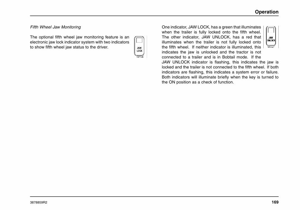
Operation
Fifth Wheel Jaw Monitoring
The optional fifth wheel jaw monitoring feature is anelectronic jaw lock indicator system with two indicatorsto show fifth wheel jaw status to the driver.
One indicator, JAW LOCK, has a green that illuminateswhen the trailer is fully locked onto the fifth wheel.The other indicator, JAW UNLOCK, has a red thatilluminates when the trailer is not fully locked ontothe fifth wheel. If neither indicator is illuminated, thisindicates the jaw is unlocked and the tractor is notconnected to a trailer and is in Bobtail mode. If theJAW UNLOCK indicator is flashing, this indicates the jaw islocked and the trailer is not connected to the fifth wheel. If bothindicators are flashing, this indicates a system error or failure.Both indicators will illuminate briefly when the key is turned tothe ON position as a check of function.
3878859R2 169

Operation
170 3878859R2

Maintenance Instructions
SECTION 7 — MAINTENANCE INSTRUCTIONS
Introduction
WARNING
If the owner/operator of the vehicle is a skilledtechnician and intends to perform the vehiclemaintenance and servicing, he/she is stronglyurged to purchase and follow the appropriateInternational® service manuals or DiamondISIS® CD-ROM. Ordering information is includedat the back of this manual. Failure to properlyperform maintenance and servicing procedurescould result in property damage, personal injury,or death.
Your vehicle has been engineered and manufactured to provideeconomical service. However, it is the owner’s responsibility tosee that the vehicle receives proper care and maintenance toassure high performance.
Quality International® service parts are available through yourInternational® Truck Dealer. If International® service parts arenot used, the owner must make sure that the parts used areequivalent to International® service parts.
As with any vehicle, care should be taken to avoid being injuredwhen performing maintenance or repairs or making any checks.Improper or incomplete service could result in the vehicle notworking properly, which in turn, may result in personal injury ordamage to the vehicle or its equipment. If you have any question
about performing some service, consult your International®Truck dealer or have the service done by a skilled technician.
Maintenance Guidelines
WARNING
Failure to perform proper maintenance andservice could result in property damage, personalinjury, or death.
WARNING
Making modifications to any part, component, orsystem of the vehicle, can adversely affect thequality and reliability of your vehicle and must beprevented. Modifications to systems could resultin property damage, personal injury, or death.
WARNING
Use only genuine International truck serviceparts. The use of inferior parts can adverselyaffect the quality and reliability of your vehicle,which could result in property damage, personalinjury, or death.
3878859R2 171

Maintenance Instructions
WARNING
To prevent property damage, personal injury,or death, take care when performing anymaintenance or making any check or repair.Some of the materials in this vehicle may alsobe hazardous if used, serviced, or handledimproperly. If you have any questions pertainingto the service, have the work done by a skilledtechnician.
WARNING
To prevent property damage, personal injury, ordeath when servicing the vehicle, park on a flatlevel surface, set the parking brake, turn off theengine, and chock the wheels.
WARNING
Always disconnect the ground battery terminalfirst, then the positive cable. When reconnectingthe battery cables, connect the positive cablesfirst, and then reconnect the negative cables.Failure to follow this warning may result in adirect battery short which is a fire or explosionhazard which could result in property damage,personal injury, or death.
CAUTION
To prevent damage to electrical componentsduring electric welding operations, follow thesecautions: Prior to electric welding, disconnectany negative and positive battery cables thatconnect the batteries to the vehicle. Be surethe detached connectors are not touchingthe vehicle. If welding close to an electroniccomponent, temporarily remove that component.Attach the welder ground cable as close aspossible to the part being welded.
When servicing your vehicle always:
1. Turn off the ignition switch, unless the procedure calls for arunning engine.
2. Set the parking brake and chock the wheels.
3. Use support stands, not a jack, whenever you must be undera raised vehicle.
4. Do not smoke.
5. Wear safety glasses for eye protection.
6. Operate engine only in a well-ventilated area.
7. Do not work on brakes or clutch unless proper precautionsare taken to avoid inhaling friction material dust.
8. Do not wear loose clothing, hanging jewelry, watches orrings. Tie up long hair and avoid rotating machinery.
9. Avoid contact with hot metal parts; allow hot components tocool before working on them.
172 3878859R2
Maintenance Instructions
10. Correct any problems that were revealed during inspectionprior to operating the vehicle.
Supporting Your Vehicle for Service
WARNING
Always use floor stands to support the vehiclebefore working under it. Using only a jack couldallow the vehicle to fall resulting in propertydamage, personal injury, or death.
When performing service repairs on a vehicle, first:
1. Park vehicle on level concrete floor.
2. Set parking brake and/or block wheels to prevent vehiclefrom moving.
3. Select jack with a rated capacity sufficient to lift thevehicle.
4. Raise vehicle with jack applied to axle. (Do not usebumper as a lifting point.)
5. Support vehicle with floor stands under axle(s).
If axle or suspension components are to be serviced, supportvehicle with floor stands under frame side members, preferablybetween the axles.
Chassis Lubrication
New vehicles are lubricated at the factory. After the vehicleis placed in operation, regular lubrication and maintenanceintervals, based on the type of service and road conditions,should be established. The loads carried, speed, road andweather conditions all contribute to the frequency of lubricationintervals. Thorough lubrication and maintenance at the specifiedintervals will insure Outstanding Life Cycle Value and will reduceoverall operating expense.
In some types of operation, and where operating conditions areextremely severe (such as in deep water, mud or unusually dustyconditions), the vehicle may require re-lubrication after every 24hours of operation.
Only lubricants of superior quality, such as Fleetrite® lubricants,should be used. The use of inferior products will reduce theservice life of the vehicle or result in failure of its components.Navistar, Inc. recommends the use of Fleetrite® lubricants andOEM original equipment parts.
The lubrication intervals specified should be performed atwhatever interval occurs first, whether it is miles (kilometers),hours, or months.
These intervals are provided in SECTION 8 — MAINTENANCEINTERVALS AND SPECIFICATIONS
3878859R2 173

Maintenance Instructions
Air Conditioning Service Checks
Have your air conditioning system serviced each spring. Therefrigerant charge, cleanliness of condenser-evaporator cores,cab filter, and belt condition are essential to air conditioningperformance.
Remove the fresh air filter(s) once each season and checkfor dirt, lint, etc. Replace if necessary. Vehicles operating inunusually dusty conditions may require inspecting and replacingthe air filter(s) more often.
To reduce costs, the filter(s) may be carefully power-washed witha soap solution and reused. Be sure to wash and rinse both sidesand be sure to keep the spray head at least six inches away fromthe filter to prevent damage.
Correct airflow may be restored by either replacing the filter(s),which can be done without tools, or by cleaning the filters.
HVAC Filters
NOTE: There are three possible cab HVAC filter configurations;top access, side access and front access HVAC filter housings.
Side Access HVAC Filter
1. Filter Access Door
2. Air Intake Housing
Cab HVAC Filter Replacement – Side Access
1. Unlatch and remove filter access door.
2. Remove filter by pulling filter out of air intake housing.
3. Install new filter by sliding filter into air intake housing.
4. Install filter access door and latch in place.
174 3878859R2

Maintenance Instructions
Front Access HVAC Filter
1. Air Intake Housing
2. Screws
3. Filter Access Door
Cab HVAC Filter Replacement – Front Access
1. Turn screws counterclockwise one quarter turn andopen filter access door.
2. Remove filter by pulling filter out of air intake housing.
3. Install new filter into air intake housing.
4. Close and secure filter access door by turning screwsclockwise one quarter turn.
Recirculation Filters
The recirculation filters are mounted on the left and right sides ofthe HVAC unit which is located in-cab under the left side dash.
1. Recirculation Filter
2. HVAC Unit
Cab HVAC Filter Replacement
1. Remove by gently pulling filter away from HVAC unit.
2. Install new filter onto HVAC unit.
3878859R2 175

Maintenance Instructions
Sleeper HVAC Filter
1. Air Intake
2. Filter
3. Lower Bunk Platform
Sleeper HVAC Filter Replacement
1. Raise lower bunk platform.
2. To avoid damaging the filter, carefully grasp the end ofthe filter and pull it up and out.
3. Slide a new (or cleaned) filter fully into the slot bypressing down on the outer two edges of the filter’s topsurface.
4. Close lower bunk platform.
Axles
Front Axle
Inspection and Lubrication
Check to make sure that the front axle mounting U-bolts,attaching or mounting bolts and nuts are securely tightened.Loose or misaligned front axles will affect vehicle alignment,front tire wear, and handling.
Re-torque the U-bolt nuts after the first 1,000 miles (1,600 km)and every 36,000 miles (58,000 km) thereafter.
Observe the following when checking the front axle for damaged,binding, or worn parts, and adequate lubrication:
• Kingpin wear inspection requires that no weight is on thetires.
• Kingpin and kingpin bushing lubrication requires that thevehicle weight is off tires and the front wheels be turned fullyto the left or right prior to installing grease distribution.
• Kingpin thrust bushing lubrication requires that the vehicleweight is resting on the tires.
• Power grease guns may be used: however, a hand-pumpedgrease gun is recommended for optimal grease distributionwithin each component joint.
176 3878859R2

Maintenance Instructions
• Inspect, lubricate and adjust the wheel bearings at regularintervals. Refer to SECTION 8 — MAINTENANCEINTERVALS AND SPECIFICATIONS for the correctintervals, lubricants, and torques.
Normal Maintenance
During operation, the air and oil inside the hub/wheel cavityexpands. It is normal for a mist of oil to be present on theoutside of the hubcap around the vent slit or hole. Over time,if not wiped off, this film may collect dust and appear unsightly.If the entire face and end of the hubcap become wet with oil,investigate the cause. Refer to the Service Manual for repairprocedures.
Routinely clean the hubcap to ensure that the lubricant levelcan be easily observed through the clear window as intended.In situations where the window is clean on the outside butdiscolored on the inside, check the lubricant level by removingthe rubber fill/vent plug and insert a finger into the hole.
The specified lubricant level for International® clear window typehubcaps is from the minimum line to 5/16 inch (.8 cm) above theminimum line.
If the lubricant level suddenly drops dramatically below theminimum level, see the Service Manual for diagnostic procedure.
Alignment
Maintaining front axle alignment is very important to achievingmaximum tire life and vehicle control. Inspecting steer axle tiresin the first 3,000 (4828 km) to 10,000 (16,094 km) service mileswill generally show if tires are wearing normally.
• Rapid outside shoulder wear on both tires indicates toomuch toe-in.
• Rapid inside shoulder wear on both tires indicates too muchtoe-out.
• Excessive wear on the inside or outside of one steer tirebut not the other can indicate a toe-in or toe-out conditioncoupled with a misaligned front or rear axle.
• Pulling to the right or left can indicate misalignmentof the front or rear axle, unequal tire pressures, or adamaged/mismatched tire.
Refer to the Tires subsection for additional related information.
Rear Axle
Inspection and Lubrication
Check to make sure that the rear axle mounting U-bolts,attaching or mounting bolts and nuts are securely tightened.Loose or misaligned rear axles will affect vehicle alignment, tirewear, and handling. Refer to SECTION 8 — MAINTENANCEINTERVALS AND SPECIFICATIONS for torque specifications.
Check the rear axle oil level. Proper oil level minimizes gearwear, heat and damage to the wheel bearings and seals. Theoil level should be at the lower edge of the level inspection holewhen the vehicle is on level ground. Add oil as necessary.
Refer to SECTION 8 — MAINTENANCE INTERVALS ANDSPECIFICATIONS for additional information.
3878859R2 177

Maintenance Instructions
Locking Differential
Vehicles which have a locking differential have the appropriateoperators manual supplied with the vehicle. Refer to this manualfor maintenance checks.
Brakes
General Information
WARNING
To prevent personal injury or death, preventbreathing brake lining fiber dust. Always use arespirator while performing brake maintenance.Follow precautions listed below.
WARNING
Always check and maintain brakes in propercondition and adjustment. Out of adjustmentbrakes could cause reduced braking ability andresult in property damage, personal injury, ordeath.
All new International® vehicles use nonasbestos brake linings.However, exposure to excessive amounts of brake material dustmay be a potentially serious health hazard.
Follow these precautions:
• Always wear a respirator approved by National Institute ofOccupational Studies of Health (NIOSH) or Mine Safety andAppliance (MSA) during all brake service procedures. Wearthe respirator from removal of the wheels through assembly.
• Never use compressed air or dry brushing to clean brakeparts or assemblies.
• Clean brake parts and assemblies in the open air. Duringdisassembly, carefully place all parts on the floor to avoidgetting dust into the air. Use an industrial vacuum cleanerwith a HEPA filter system to clean dust from the brakedrums, backing plates, and other brake parts. After usingthe vacuum, remove any remaining dust with a rag soakedin water and wrung until nearly dry.
• Never use compressed air or dry sweeping to clean the workarea. Use an industrial vacuum cleaner with a HEPA filtersystem and rags soaked in water and wrung until nearly dry.Dispose of used rags with care to avoid getting dust intothe air. Use an approved respirator when emptying vacuumcleaners and handling used rags.
• Worker cleanup. Wash your hands before eating, drinking,or smoking. Vacuum your work clothes after use and thenlaunder them separately, without shaking them, to preventfiber dust from getting into the air.
178 3878859R2

Maintenance Instructions
Air Brakes
Inspection and Adjustment
WARNING
Always chock the wheels when manuallyreleasing the spring brakes, or the vehicle couldroll causing property damage, personal injury, ordeath.
WARNING
Under no circumstances should the springbrake section of the spring and brake chamberbe disassembled. Disassembly will release apowerful spring which could result in propertydamage, personal injury, or death.
WARNING
Brake Automatic Slack Adjusters (ASA’s) shouldnot need to be manually adjusted in service.ASA’s should not routinely have to be adjustedto correct excessive push rod stroke. Excessivestroke indicates that a problem exists with thefoundation brake, ASA, brake actuator, otherbrake system components, or their installationor adjustment.
In the event that a manual adjustment must bemade (although this should not be a commonpractice), a service appointment and fullfoundation brake, ASA, and other brake systemcomponent inspection must be conducted assoon as possible to ensure the integrity of theoverall brake system prior to returning the vehicleto service.
Failure to follow this warning may result inproperty damage, personal injury, or death.
A regular schedule for periodic cleaning, lubrication, adjustmentand inspection should be established, based on the typeof vehicle operation. It is difficult to predetermine an exactmaintenance interval (time or mileage), since vehicles will beused in a wide variety of applications and conditions. If youare uncertain of the proper schedule and procedures for yourvehicle, contact your International dealer.
Periodic checking of push rod travel or brake adjustment isessential for good braking. Push rod travel should be checkedevery service interval to determine if adjustment is necessary.
3878859R2 179

Maintenance Instructions
Brake chamber push rods on original equipment chambers nowincorporate an overstroke indicator (an orange paint markernear the base of the push rod) to aid adjustment checks. If thepush rod is clean and the orange marker can be seen protrudingfrom the chamber when the brakes are applied, the brakesrequire adjustment.
Slack adjusters should also be checked to ensure properoperation of the adjuster mechanism at every interval. Push rodtravel should be less than the maximum allowed stroke withoutbrakes dragging.
Inspect brake linings every maintenance interval. When brakeshoes (or pads) are worn to within 1/16 inch (1.6 mm) of rivets(or backing plates), as indicated by a line or other feature on theedge of most brake shoes (or pads), brake shoes (or pads) mustbe replaced.
This inspection or adjustment should only be performed byqualified service personnel and must be in accordance withinstructions provided by the Service Manual.
NOTE: Do not overlook the brakes on the trailer either. Brakecondition on a trailer is just as important as the tractor. Properbrake balance on trucks and tractor trailers is essential for goodbraking.
At least once a year, the entire brake system must be inspectedby a trained mechanic. Deteriorated components or componentsworn outside of specifications must be replaced. Check:
1. Rubber components for condition, cracks, tears, wear,missing components, etc.
2. Condition of drums, brake chambers, and slackadjusters for wear, corrosion, maladjustment, cracks,missing components, etc.
3. For air leaks. No air leakage is permissible. Also,check for air leaks with parking brake disengaged andwheels chocked.
4. Hose or pipes for rust, damage, deterioration.
5. Proper operation of service, parking, and trailer brakecontrols.
6. The condition and full insertion of the ABS wheel speedsensors, wiring, and connectors.
7. Proper ABS wheel speed sensor-to-exciter teeth gap.
Air Dryer
General Information
NOTE: The use of an air dryer does not eliminate the need toperiodically drain the air tanks.
The air dryer removes humidity (water), air compressor oil, anddirt from the incoming compressed air, thus protecting the airsystem against deterioration and restriction.
The air dryer is installed between the air compressor dischargeline and the air tanks. The air dryer has a desiccant cartridgeand a filter which is serviced as an assembly. Moisture from theair collects on the desiccant and is automatically discharged.
Life and performance of the air dryer depends on usage, airhumidity levels, environmental temperatures, air compressor oil
180 3878859R2

Maintenance Instructions
control, and desiccant quantity. Regularly check the desiccant,purge valve and air dryer heater performance.
Desiccant Filter
Open reservoir drain valves and check for presence of water.Small amounts of water due to condensation is normal. If thewet, primary, or secondary tanks are collecting an abnormallyhigh amount of water between regular air tank drain intervals,replace the air dryer desiccant.
The air dryer desiccant replacement interval may vary; it isgenerally recommended that the desiccant be replaced every12 months for small air dryers, like the Bendix AD-IP®, or every24 months for large air dryers, like the Bendix AD-9® or BendixAD-IS®. If experience has shown that extended or shortenedlife has resulted for a particular installation, then the intervalshould be increased or reduced accordingly.
Purge Valve
Check that the purge valve opens and expels moisture when theair governor shuts off the air compressor. Air should escaperapidly and then quickly stop. If the purge valve does not openor you can hear a slight audible air leakage past the valve forlonger than 30 seconds, the valve may be sticking and shouldbe rebuilt. Purge valves may also stick if the air dryer heater hasfailed and ice is clogging the valve.
Heater
Check that the air dryer heater activates at temperatures belowfreezing. With the vehicle in a cold environment and before the
engine is started, turn on the ignition and touch the air dryerhousing. It should be warmer than other metallic items on thevehicle. If some warmth cannot be felt, it may indicate that theheater element or the wiring powering it should be serviced.
Air Reservoir/Tanks Moisture Draining
Moisture taken in with the air through the compressor inlet valvescollects in the air tanks. The wet tank is the first tank to receive airfrom the air dryer and therefore collects most of the remainingmoisture that was not removed by the air dryer. Drain the wettank reservoir every day at the end of the trip. Drain the primaryand secondary tanks periodically. Periodically, manually draineach reservoir by opening the drain cock located either on thebottom of the tank or in the end of the tank. Make sure thedrain passage is not plugged. For ease of draining, some or allair tank drain valves may be equipped with optional pull cords.There must be some air pressure in the system to ensure properdrainage. Close the drain cocks after all moisture has beenexpelled. Drain the wet tank daily at the end of each trip to purgecollected water and prevent ice formation inside the tank whenthe vehicle is shut off in cold weather. If you are unsure whichtank is the wet tank, drain all tanks daily.
On vehicles equipped with automatic drain valve(s), moistureand contaminants are automatically removed from the reservoirto which it is connected. It operates automatically during eachcompression cycle and requires no manual assistance or controllines from other sources.
The Bendix AD-IS® air dryer has an integral wet/purge tankwhich automatically purges itself and the desiccant of collectedwater at the end of each compressor cycle.
3878859R2 181

Maintenance Instructions
ABS Connections and Sensors
Periodically, push together the ABS wiring connections to ensurethey are fully-seated. Press the wheel speed sensors into theirmounting collars to ensure they are fully-seated.
Cab
Care of Vehicle
Washing and Waxing
Frequent and regular washing will lengthen the life of your newvehicle’s painted finish and bright metal trim.
Wash your vehicle often with warm or cold water to remove dirtand preserve the original luster of the paint. Never wash thevehicle in the direct rays of the hot sun or when the sheet metalis hot to the touch, as this may cause streaks on the finish. Donot use hot water or strong soaps or detergents, as this may etchthe paint or exposed metal/bright surfaces. Do not wipe off dirtwhen the surface is dry, as this will scratch the paint or exposedmetal/bright surfaces.
Always make sure that steps and grab handles are clean andfree of road grime, grease, ice, and other debris.
Prior to using any wax or polish, the vehicle must be thoroughlywashed to avoid scratching the finish.
Bright Metal Care
To preserve the bright look of your vehicle’s trim (grilles,bumpers, etc.) use only mild detergents and lukewarm water
for cleaning. Damage to these parts can occur if cleaningsolutions having excessive acidity or alkalinity (pH) are used.Also, the higher the solution temperature ranges, the morecaustic the cleaner’s chemical compounds become. However,if high-pressure washing equipment and washing compoundsare used, satisfactory results can be achieved, if the solutionhas a pH value between 4 and 8 and the temperature does notexceed 160°F (71°C). Solutions that are more acidic or morealkaline will attack the metallic coating.
If you are having difficulty with your washing compound, contactyour local supplier for the acidity/alkalinity (pH) specification.
A nonabrasive chrome cleaner may be used sparingly to cleanthe bright metal. Do not use steel wool. Use of automobilewax or polish on bright metal usually will restore the originalbrightness.
Upholstery Care
Use a whisk broom and vacuum cleaner to remove loose dustand dirt from upholstery and floor. Vinyl and woven plasticupholstery can be washed with warm water and mild soap.Remove soap residue and wipe dry. If commercial cleaners areused, follow instructions supplied with cleaner.
Exposed Rubber and Unpainted Plastic Parts
To better protect plastic surfaces from fading, use Meguiar’s #40vinyl and rubber cleaner/conditioner. Spread evenly with spongeor towel and allow to penetrate. Buff off excess product withclean cloth.
182 3878859R2

Maintenance Instructions
Clutch
Pedal Free Travel
All International® ProStar®+ Series vehicles are equipped withpull type clutches. If a non-self-adjusting clutch (clutches otherthan the Eaton Solo series) was selected, free pedal mustbe checked each time the vehicle chassis is lubricated. Iffree pedal is less than 1/2 inch (13 mm), the clutch must beadjusted. Contact your International® Truck dealer for properclutch adjustment procedures. After proper clutch adjustment,clutch free pedal should be between 1.25 and 1.75 inch (32mm and 44 mm) and the release bearing should contact theclutch brake with 1/2 to 1 inch (13 mm to 25 mm) of clutchpedal travel remaining. Free pedal and clutch brake should beadjusted by lengthening (increases free pedal and decreasesclutch brake squeeze) or shortening (decreases free pedal andincreases clutch brake squeeze) the horizontal rod if outside ofthis specification. Contact your International® Truck dealer forproper linkage adjustment procedures.
NOTE: Proper clutch and linkage adjustment will provideadequate clearance between the release yoke fingers and therelease bearing as well as between the release bearing andthe clutch brake for proper operation. Improper adjustment maycause improper clutch operation, reduce clutch life, and mayvoid the clutch warranty.
Clutch cross-shafts and throw-out bearings must be lubricatedeach time the vehicle chassis is lubricated to ensure smoothclutch activation and long life.
All new International® ProStar®+ vehicles use non-asbestosclutch linings. However, exposure to excessive amountsof clutch material dust (whether asbestos or non-asbestos,fiberglass, mineral wool, aramid, ceramic or carbon) is apotentially serious health hazard.
WARNING
To prevent personal injury or death, preventbreathing clutch lining fiber dust. Always wear arespirator when doing clutch lining maintenance.
Persons who handle clutch linings should follow the sameprecautions as outlined for handling brake linings.
Hydraulic Clutch
Your vehicle is equipped with a hydraulic clutch actuation system.The reservoir is located just below the cowl, left of center on thefirewall.
CAUTION
To prevent vehicle and/or engine componentdamage, use only approved hydraulic clutchfluid (DOT 3 or DOT 4 brake fluid) in the clutchhydraulic system. Do not mix different typesof brake fluid. The wrong fluid will damage therubber parts of the system, causing loss of clutchfunction.
3878859R2 183

Maintenance Instructions
CAUTION
To prevent vehicle and/or engine componentdamage, do not allow the fluid level in thereservoir to go below the MIN line. If too muchair enters, the hydraulic system will not operatecorrectly, and the clutch could be damaged.
1. Reservoir
2. Cap
If the fluid level is below the MIN line, remove cap and fill thereservoir with DOT 3 or DOT 4 brake fluid until the level reachesthe MAX line.
Electrical
Batteries
Battery life and performance varies greatly depending onduty cycle. Conditions such as short runs between starts,low ambient operating temperatures, using battery currentwithout the engine running, and vibration will reduce batterylife. Battery life is also affected by the condition of interrelatedcomponents, such as alternators, battery cables, connections,engine startability, starter, etc. To maximize battery life, it isimportant to keep electrical components, battery boxes, and theengine in top condition and to minimize or eliminate electricalloads when the engine is not running.
Battery life can be extended by keeping the batteries fullycharged at all times. Periodically charging the batterieswith a battery charger may be able to charge the batteriesmore completely than the vehicle’s alternator in certainsevere applications. Use a battery charger (float charger)that automatically reduces amperage or shuts off when thebatteries are fully charged. Use of a Midtronics 55-Amp PowerSupply/Smart (Battery) Charger, Model Number PCX550, PartNumber PSC550CCKIT (or equivalent), available through yourInternational dealer, is recommended.
Cold batteries resist charging. Battery performance can beimproved by regularly or even periodically storing vehicles andcharging batteries with an automatic float charger for 8 to 24hours in a warm garage during the cold winter months.
184 3878859R2

Maintenance Instructions
CAUTION
Allowing batteries to become heavily dischargedand exposed to subfreezing weather will causethem to freeze and become damaged.
Your vehicle utilizes maintenance-free batteries, which will notrequire the periodic addition of water. Wipe the tops of thebatteries clean to avoid a slow current flow through the dirt,resulting in a loss of charge. Be sure the terminals are clampedtightly and that the battery is clamped securely in the batterybox.
For best results:
• Do not mix and match battery models/manufacturers in thesame battery pack.
• Do not use batteries with differing CCA ratings in the samebattery pack.
• Do not use batteries with more than one year difference inthe installed age of batteries in the same battery pack.
Battery Cables
CAUTION
When working around the terminals and battery,use extra care to prevent shorting. A goodpractice is to insulate pliers and screwdrivers.Do not check battery condition by shorting(flashing) across terminals.
Battery cable terminals must be clean and tight. Use a mixtureof hot water and common baking soda for removing terminal
corrosion and for cleaning the top of the battery. Brighten thecontact surfaces with steel wool, apply a light coat of lubricantsealing grease, such as Fleetrite® 472141-C1 or equivalent ora spray protectant, and reassemble. Be sure the terminals areclamped tightly.
Electrical Charging and Starting System Test
At every PM. fully charge the batteries using an automaticfloat charger. Then, have a qualified technician perform anelectrical system test using an International® Electronic SystemTester (Midtronics inTELLECT EXP HD Expandable ElectricalDiagnostics Platform available through your local Internationaldealer) to catch electrical system problems before they causefurther damage to the batteries and prevent a stranded vehicle.The test will check for alternator amperage output, startercurrent draw, and battery amperage capacity. This type oftesting will detect weaknesses that may not yet be apparentduring normal daily operations.
Terminal Inspection-Cleaning-Corrosion Protection
Periodically inspect electrical connectors on the engine, battery,and frame for corrosion and tightness. Inspect exposed cablesfor fraying or signs of abrasion. Exposed terminals, such ascranking motor, alternator, and feed-through studs shouldbe cleaned and recoated with a dielectric grease, such asFleetrite® 472141–C1 or equivalent paste or spray protectant.The inspection/cleaning/corrosion protection should includefeed-through connections, power and ground cable connectionsfor batteries, engines, and the starter stud.
3878859R2 185

Maintenance Instructions
Connectors that are more subject to corrosion may bedisassembled and sprayed internally with a light coating ofdielectric grease. Use grease sparingly, as too much grease willnot allow air to escape from the connection and this compressedair will push out the seals in the electrical connectors.
Accessory Feed Connections
WARNING
Electrical circuits are designed with a particularwire gauge to meet the fuse and circuit breakercurrent rating. Do not increase size of fuse orcircuit breaker or change type of breaker suppliedwith your truck. To do so could cause wiring tooverheat and possibly burn, resulting in a firewhich could cause property damage, personalinjury, or death.
Vehicle electrical systems are complex and often includeelectronic components, such as engine and transmissioncontrols, instrument panels, antilock brakes, etc. While mostsystems still operate on battery voltage (12 volts), somesystems can be as high as 90 volts or as low as 5 volts.Refer to the Electrical Circuit Diagram manuals, available fromyour International dealer, to ensure that any body lights andaccessories are connected to circuits that are both appropriateand not overloaded. No modification should be made to anyvehicle control system without first contacting your Internationaldealer.
Fuses and Relays
Fuses and relays are located inside the cab within the fusepanel cover. Refer to the schematic located on the fusepanel cover in the cab, the schematic on the fuse cover inthe luggage compartment, or the Fuse Panel Schematiclocated in SECTION 8 — MAINTENANCE INTERVALS ANDSPECIFICATIONS of this manual for fuse or relay replacement.
Engine
General Information
NOTE: For complete operation and maintenance informationpertaining to your engine, refer to the Engine Operation andMaintenance Manual provided with the vehicle.
For effective emission control and low operating cost, it isimportant that maintenance operations be performed at thespecified periods or mileage intervals indicated in the EngineOperation and Maintenance Manual.
Service intervals are based on average operating conditions. Incertain environments and locations, more frequent servicing willbe required.
The required maintenance operations may be performed at aservice establishment. Any replacement parts used for requiredmaintenance services or repairs should be genuine OEM serviceparts. Use of inferior replacement parts hinders operation ofengine and emission controls and can reduce engine life and/orjeopardize the warranty.
186 3878859R2

Maintenance Instructions
Receipts covering the performance of regular maintenanceshould be retained in the event questions arise concerningmaintenance. The receipts should be transferred to eachsubsequent owner of the engine (vehicle).
Engine fluids and contaminated material
GOVERNMENT REGULATION: Engine fluids(oil, fuel, and coolant) may be a hazard to humanhealth and the environment. Handle all fluids andother contaminated materials (e.g., filters, rags) inaccordance with applicable regulations. Recycleor dispose of engine fluids, filters, and othercontaminated materials according to applicableregulations.
Scheduled Maintenance
For information regarding routine scheduled maintenance suchas replacement of oil, filters, coolant, belts, belt tensioners, etc.,and inspection and adjustment of items such as valve lash, etc.,refer to the Engine Operation and Maintenance Manual suppliedwith the vehicle.
Air Induction System
WARNING
To prevent personal injury or death whenperforming maintenance and repairs to anyturbocharged engine with engine air inlet pipingdisconnected, a turbocharger compressor airinlet protective shield should be installed overthe turbocharger air inlet.
Once each year perform a complete inspection of the airinduction system. In areas where road salt is used, theinspection consists of disassembling the joints of each metalcomponent and inspecting for salt build-up that can causeparticles to flake off and enter the engine combustion chambers.
If evidence of corrosion is found (usually appears at the pipeconnections), use a wire brush to clean the inside of the pipesand inside of the rubber hoses.
If the intake pipes are pitted at the joint ends, use RTV Siliconeto seal the joints. Be certain that no excess material that can bepulled into the engine is on the inside of the pipe. If the servicecondition of the pipes, hoses or clamps is questionable, replacethose parts.
• Check for loose hoses and clamps.
• Check for ruptured, bulging, or collapsed hoses.
• Check air cleaner housing for cracks.
3878859R2 187

Maintenance Instructions
Air Restriction Gauge
The air restriction gauge indicates how much engine air cleanerfilter capacity has been used and how much filter capacityremains. It measures maximum restriction of the filter elementwhen the engine is operated at full load and locks at thatpoint. This feature gives the operator the capability of readingmaximum restriction with the engine shutdown.
The gauge is mounted on the forward side of the air cleanerhousing, or optionally on the center dash panel/wing panel.
It is recommended that the operator not reset the gauge until ithas been determined if air cleaner service is required.
The initial restriction with a new air filter element will vary with aircleaner design and installation.
After servicing the filter element, reset the yellow indicator bypushing the reset button and releasing it. The yellow indicatorwill drop to near or below the window so the air restriction gaugecan be reused.
NOTE: After starting engine, indicator may be seen in lower partof window. This is normal and should not be mistaken as a signalfor element service.
188 3878859R2
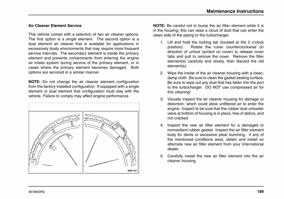
Maintenance Instructions
Air Cleaner Element Service
This vehicle comes with a selection of two air cleaner options.The first option is a single element. The second option is adual element air cleaner that is available for applications inexcessively dusty environments that may require more frequentservice intervals. The secondary element is inside the primaryelement and prevents contaminants from entering the engineair intake system during service of the primary element, or incases where the primary element becomes damaged. Bothoptions are serviced in a similar manner.
NOTE: Do not change the air cleaner element configurationfrom the factory installed configuration. If equipped with a singleelement or dual element that configuration must stay with thevehicle. Failure to comply may affect engine performance.
NOTE: Be careful not to bump the air filter element while it isin the housing; this can raise a cloud of dust that can enter theclean side of the piping to the turbocharger.
1. Lift and hold the locking tab (located at the 2 o’clockposition). Rotate the cover counterclockwise (indirection of unlock symbol on cover) to release covertabs and pull to remove the cover. Remove the filterelement(s) carefully and slowly, then discard the oldelement(s).
2. Wipe the inside of the air cleaner housing with a clean,damp cloth. Be sure to clean the gasket sealing surface.Be sure to wipe out any dust that has fallen into the portto the turbocharger. DO NOT use compressed air forthis cleaning!
3. Visually inspect the air cleaner housing for damage ordistortion, which could allow unfiltered air to enter theengine. Inspect to be sure that the rubber dust unloadervalve at bottom of housing is in place, free of debris, andnot cracked.
4. Inspect the new air filter element for a damaged ornonresilient rubber gasket. Inspect the air filter elementbody for dents or excessive pleat bunching. If any ofthe mentioned conditions exist, obtain and install analternate new air filter element from your Internationaldealer.
5. Carefully install the new air filter element into the aircleaner housing.
3878859R2 189

Maintenance Instructions
6. With the air cleaner cover latch at the 1 o’clock position,align cover tabs with corresponding slots. Push thecover into the slots. Rotate the cover clockwise (indirection of lock on cover) until the locking tab snapsinto its locked position.
7. When servicing is completed, reset air restriction gaugeby pushing and holding the reset button and releasingit. The yellow indicator will drop below the window. Theair restriction gauge is now ready for the next operatingcycle.
NOTE: After starting engine, the indicator may be seen in thelower part of the window. This is normal and should not bemistaken as a signal for element service.
190 3878859R2

Maintenance Instructions
Troubleshooting
No Restriction Reading
POSSIBLE CAUSES HOW TO CHECK
Plugged fitting or vacuum line Remove the gauge and apply a vacuum until it is locked up at the red zone. Re-insert the gauge andhold in the reset button. Indicator will fully return unless line or fitting is plugged. A slow return isnormal due to safety filter in fitting.
Leak in vacuum line Apply vacuum to gauge until locked up at red zone. Re-connect gauge and close end of line airtight.Hold in reset button. Indicator will drop slightly and then not move unless vacuum line has a leak.
Leak in gauge Repeat above except close gauge connection airtight.
Engine airflow too low to generate arestriction reading
Turbocharged engines must be full load to pull full engine airflow.
Air cleaner element split open Visually inspect element.
High Restriction Reading
POSSIBLE CAUSES EXPLANATION
Plugged outer element Particles in outer filter media restrict airflow. Replace outer element.
Plugged inner element (if equipped) Replace inner element.
Plugged inlet screens or ducts Check system upstream from restriction tap for debris, damage or improper installation.
Heavy snow or rain Temporary high restriction can occur during a rain or snow storm; it disappears after drying out.If gauge is locked up at red zone, check elements for damage. Reset gauge. Reuse element,recheck gauge reading.
3878859R2 191

Maintenance Instructions
Charge Air Cooler And Radiator Core Inspection AndCleaning
Inspection and Cleaning
With the engine off, visually inspect the charge air cooler coreand radiator core assembly for debris and clogging of externalfins. Prior to engine operation, remove any debris blocking thecore.
The cores may be cleaned by externally backflushing themwith compressed air and/or water. Use high pressure air orwater Thexton radiator cleaning wand with 90-degree tip P/N4106-NAV available from you International dealer for bestresults.
Cooling System
Coolant Level Check
WARNING
To prevent personal injury or death fromhot coolant or steam, use only the followingprocedure to remove the pressure cap from theradiator or expansion tank. Allow the engine tocool first. Wrap a thick, heavy cloth around thecap. Unscrew the cap slowly to allow pressureto release from under the cap. After the pressurehas been released, the pressure cap may beremoved.
WARNING
Do not exceed the pressure rating on thede-aeration tank cap. Ensure that the pressurerating of the de-aeration tank cap matches thatlisted on the side of the tank, or the tank mayburst, causing property damage, personal injury,or death.
CAUTION
If the coolant should get extremely low andthe engine very hot, let the engine cool forapproximately 15 minutes before adding coolant;then, with the engine running, add coolant slowly.Adding cold coolant to a hot engine may crackthe cylinder head or crankcase. Never use wateralone.
Filling Instructions
NOTE: If system has been drained, fill with fresh 50/50 dilutedconcentrate coolant or 50/50 pre-mixed coolant. If the systemhas been flushed with water, a significant amount of thefreshwater flush will remain in the system. In this case refillingwith a mixture with a higher percentage (75%) of coolantconcentrate is advised in order to achieve a final mixture closeto 50/50.
192 3878859R2
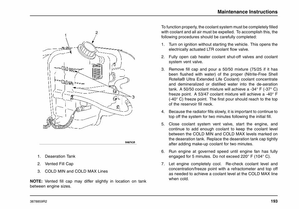
Maintenance Instructions
1. Deaeration Tank
2. Vented Fill Cap
3. COLD MIN and COLD MAX Lines
NOTE: Vented fill cap may differ slightly in location on tankbetween engine sizes.
To function properly, the coolant system must be completely filledwith coolant and all air must be expelled. To accomplish this, thefollowing procedures should be carefully completed:
1. Turn on ignition without starting the vehicle. This opens theelectrically actuated LTR coolant flow valve.
2. Fully open cab heater coolant shut-off valves and coolantsystem vent valve.
3. Remove fill cap and pour a 50/50 mixture (75/25 if it hasbeen flushed with water) of the proper (Nitrite-Free ShellRotella® Ultra Extended Life Coolant) coolant concentrateand demineralized or distilled water into the de-aerationtank. A 50/50 coolant mixture will achieve a -34° F (-37° C)freeze point. A 53/47 coolant mixture will achieve a -40° F(-40° C) freeze point. The first pour should reach to the topof the reservoir fill neck.
4. Because the radiator fills slowly, it is important to continue totop off the system for two minutes following the initial fill.
5. Close coolant system vent valve, start the engine, andcontinue to add enough coolant to keep the coolant levelbetween the COLD MIN and COLD MAX levels marked onthe deaeration tank. Replace the deaeration tank cap tightlyafter adding make-up coolant for two minutes.
6. Run engine at governed speed until engine fan has fullyengaged for 5 minutes. Do not exceed 220° F (104° C).
7. Let engine completely cool. Re-check coolant level andconcentration/freeze point with a refractometer and top offas needed to achieve a coolant level at the COLD MAX linewhen cold.
3878859R2 193

Maintenance Instructions
Coolant and Optional Coolant Filter
The cooling system in vehicles with MaxxForce® 11, 13 and 15engines, is filled at the factory with Nitrite-free Shell Rotella®Ultra ELC (Yellow) coolant. International Truck recommendsusing only the approved coolant with the 2010 cooling packages,and will not warrant these cooling systems that have not utilizedthe recommended coolant.
The label on the deaeration tank provides additionalcoolant/antifreeze information. Consult the Engine Operationand Maintenance Manual for coolant service life details.
Some engines are ordered with an optional coolant filter thatshould be replaced periodically.
For Ultra ELC equipped vehicles use only water filters withoutSupplemental Coolant Additives (SCA’s) as SCA’s are notnecessary with Ultra ELC. Any time a silicone gasket/sealexposed to the coolant is replaced while using Ultra ELC, afresh charge of silicates must be added to the coolant to protectthe new gasket/seal.
International® truck recommends Ultra ELC due to its ease ofmaintenance and lower long-term cost of operation. Any systemusing or contaminated with more than 10% conventional coolantmust be maintained like conventional coolant and receive regulartests for Supplemental Coolant Additive (SCA) levels.
Coolant Concentration Freeze Point
Cooling systems should be checked twice a year to assureproper coolant water concentrations. A 53/47 coolant/watermixture from the factory provides freeze protection down to
minus -40° F (-40° C) as well as excellent corrosion protection.A 50/50 mixture can be easily created in the shop usingundiluted coolant and water and will provide freeze protectiondown to -34° F (-36.7° C) if no further dilution is experiencedduring installation.
Concentrations greater than 67% are not recommended. Theuse of Shell Rotella® Ultra ELC pre-mixed to make up for coolantloss will assure the glycol/water concentrations stay in balance.
CAUTION
Always use Shell Rotella® Ultra ELC to top-offELC-equipped cooling systems. Failure to do somay result in the loss of extended life propertiesand will require periodic testing for SCA levels.Should top-off occur with conventional coolant(s)exceeding 10% of the total cooling systemcapacity, either drain and refill with Shell Rotella®Ultra ELC or maintain as a conventional coolantsystem using SCA’s at the recommended levels.
Antifreeze
For cooling system capacities, coolant part numbers, andother information refer to SECTION 8 — MAINTENANCEINTERVALS AND SPECIFICATIONS of this manual.
Fan Clutch
Inspect for proper operation, secure electrical connections, andair supply as appropriate. See the Service Manual for details.
194 3878859R2

Maintenance Instructions
Start cold engine and view fan to see that it is rotating slowerthan the fan pulley (fan clutch is disengaged). Achieve operatingtemperature and observe that the fan is engaged.
Fuel System
GOVERNMENT REGULATION: Diesel fuel sold foruse in 2007 and later highway vehicles must be limitedto a sulfur content of 15 parts per million (ppm).
Frequently inspect condition of fuel tanks and mountinghardware, fuel tank cap and vent, fuel lines, clips and routing.At every PM (or daily if necessary) drain water and sedimentfrom the fuel/water separator filter (if equipped). If the vehicle isequipped with an optional Davco® fuel/water separator, inspectthe level of the fuel in the see-through globe and replace thefuel/water separator filter element if the fuel level has reachedthe top of the globe. In all cases, be sure to use the properfuel/water separator filter element with the correct part numberand filter efficiency rating.
Fuel Tank Draining and Cleaning
Periodically (annually is recommended) drain water andsediment from the fuel tank via the drain plug on the bottom ofthe fuel tank. Drain and flush sediment from fuel tank at leastevery 12 months or more frequently if fuel quality or type of fueldictates.
Since Ultra-Low Sulfur Diesel (ULSD) fuel tends to absorbmore water and engines are operating at higher temperatures,microbe growth in the fuel tanks has become more prevalent.Microbe growth results in more contaminants in the fuel andreduces fuel filter life. Since fuel tank draining does not removeall microbes, fuel tank draining alone will not eliminate theproblem. For vehicle operators experiencing microbe growth intheir fuel, the following is recommended:
1. Drain and clean the fuel tank(s) every 12 months ormore often. Clean the tanks with a professional fuel tankcleaning system (available through your dealer) or haveyour local dealer perform the service for you.
2. Treat your vehicle fuel tanks and bulk tanks regularlywith a biocide from a reputable vendor.
3. Purchase fuel only from vendors that pretreat their fuelwith biocides.
4. Periodically test the fuel supplied by your fuel vendor forthe presence of microbes.
Crankcase Ventilation Filter
Refer to the Engine Operation and Maintenance Manual for theproper replacement interval and instructions.
Frame
International® chassis are manufactured with frame rails ofHSLA steel and each must be handled in a specific manner toassure maximum service life. Before attempting frame repair ormodification, consult the Service Manual or your International®Truck Dealer.
3878859R2 195

Maintenance Instructions
Noise Emissions – Exterior
Instructions for Proper Maintenance
In order to comply with federal exterior noise regulations, yourvehicle may be equipped with noise emission items. Dependingupon the vehicle configuration, it may incorporate all or some ofthe following:
Air Intake System
• Air Cleaner – should be inspected and its location shouldnot be altered. Do not alter inlet and outlet piping.
Body
• Wheel Well – splash shields, cab shields, and underhoodinsulation should be inspected for deterioration, dislocation,and orientation and repaired or replaced as necessary.
Cooling System
• Check fan for damage to blades. Replace, if damaged,with manufacturer’s recommended parts. Inspect forfan-to-shroud interference and any damage to shroud, suchas cracks and holes.
• Fan speed ratio should not be changed and fan spacerdimensions and position should not be altered.
• Inspect for proper operation of fan clutch, making sure thatthe fan is disengaged when cooling of engine is not required.
Engine Noise Shields/Blankets
• Engine valve covers, oil pans, and block covers are made todamp out engine mechanical noise and, if needed, shouldbe replaced with original equipment parts.
Exhaust System
• Inspect for leaks at various joint connections and tightenclamps. Make visual inspection for cracks or holes inmuffler and tailpipe. Always replace with manufacturer’srecommended parts. Tailpipe elbow or offset tailpipeorientation must not be changed from standard position asoriginally received.
• To avoid abnormal changes in vehicle sound level, itis necessary for the owner to perform inspections andnecessary maintenance at the intervals shown in themaintenance schedules, and record them on the inspectionverification form provided.
Diesel Particulate Filter (DPF)
Regeneration
Collected soot particles in the Diesel Particulate Filter (DPF)are automatically burned off through normal regeneration(initiated by normal exhaust heat during the normal operation ofthe vehicle). If conditions for normal regeneration cannotbe achieved, it may be necessary to perform a parkedregeneration as indicated by the instrument panel gaugecluster warning indicators. See the Parked RegenerationProcedure in SECTION 6 — OPERATION.
196 3878859R2

Maintenance Instructions
Cleaning
If on-vehicle regeneration is unsuccessful at removing soot fromthe DPF, the DPF may need to be removed from the vehicle andbe cleaned with the appropriate machinery and processes.
Ash residue in the DPF comes primarily from fuel and oiladditives and will not burn or pass through the DPF. Ash residueaccumulates very slowly in the DPF, but must eventually beremoved to prevent excessive exhaust backpressure. If the DPFneeds to have nonregenerable soot or the ash residue removed,please take the vehicle to an International dealer.
Drive Shafts
At the regular lubrication interval, check universal joints, slipjoints, slip joint boot, and carrier bearings for any evidence ofwear or looseness. Should drive shaft vibrations occur, stop thevehicle immediately to avoid possible hazardous consequencesor damage to other components.
Suspension (Air and Steel Springs)
CAUTION
Do not adjust air suspension height to any settingother than the specified setting. Altering theheight setting will change the driveline angle andmay result in unwarrantable component damage,such as transmission component damage.
Verify drive axle air suspension height at engine oil changeintervals. See the appropriate Service Manual.
NOTE: Suspension alignment must be maintained at all times.
NOTE: Refer to SECTION 8 — MAINTENANCE INTERVALSAND SPECIFICATIONS for proper U-bolt torque values.
Periodically:
• Check condition of spring leaves for evidence of fatigue,bending or breakage.
• Check condition of suspension mounting brackets andbushings.
• Check that suspension mounts (brackets, bushings,fasteners, etc.) are tight.
• Check that torque rod mounting fasteners are tight.
• Check U-bolts as follows:
1. After the chassis has been operating under load for1,000 miles (1,600 km) or six months, whichevercomes first, the U-bolt nuts must be re-torqued.
2. Thereafter, the U-bolt nuts must be re-torquedevery 36,000 miles (58,000 km). Re-torque intervalmay be lowered to 25,000 miles (46,000 km) tosynchronize with oil change interval.
Front Suspension
The front suspension should be regularly inspected for loose,worn, or broken components. Front suspensions/axles shouldbe checked periodically for proper alignment to promotemaximum tire life.
3878859R2 197
Maintenance Instructions
On vehicles equipped with the optional front air suspension, theair suspension components, including air bags, height controlvalves, ail lines, and fittings should be inspected for wear,damage, and audible air leaks
Rear Suspension
The rear suspension should be regularly inspected for loose,worn, or broken components. Rear suspensions/axles shouldbe checked periodically for proper alignment to promotemaximum tire life. The optional International® Truck RideOptimized Suspension (IROS) components, including air bags,height control valves, air lines, and fittings should be inspectedfor wear, damage, and audible air leaks.
Steering
General Information
WARNING
Always follow recommended procedures forsteering system maintenance. Failure to maintainthe steering system in proper condition cancause reduced steering ability resulting inproperty damage, personal injury, or death.
Have a technician examine the steering mechanism. Minoradjustments could head off further problems.
Check tie rod ends, drag link ends and king pins. Jointsand fasteners must be tight. Articulating joints must be welllubricated.
Check for installation and spread of cotter pins and tightness ofnuts at both ends of tie rod and drag link.
Check that pitman arm (steering arm at steering gear) mountingis tight and locked. Check system for leaks or hose chafing.
Maintain proper power steering fluid levels.
Regularly inspect steering column joint bolts and steeringlinkage, particularly for body-to-chassis clearance.
NOTE: Have any steering problems corrected at once by aqualified service technician.
Tightening Steering Intermediate Shaft Joint Bolts
As a good maintenance practice, it is recommended thatsteering intermediate shaft joint bolts be checked for tightnessevery 120,000 miles (193,000 km) or annually, whichever occursfirst.
198 3878859R2
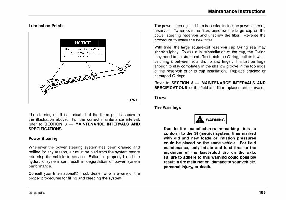
Maintenance Instructions
Lubrication Points
The steering shaft is lubricated at the three points shown inthe illustration above. For the correct maintenance interval,refer to SECTION 8 — MAINTENANCE INTERVALS ANDSPECIFICATIONS.
Power Steering
Whenever the power steering system has been drained andrefilled for any reason, air must be bled from the system beforereturning the vehicle to service. Failure to properly bleed thehydraulic system can result in degradation of power systemperformance.
Consult your International® Truck dealer who is aware of theproper procedures for filling and bleeding the system.
The power steering fluid filter is located inside the power steeringreservoir. To remove the filter, unscrew the large cap on thepower steering reservoir and unscrew the filter. Reverse theprocedure to install the new filter.
With time, the large square-cut reservoir cap O-ring seal mayshrink slightly. To assist in reinstallation of the cap, the O-ringmay need to be stretched. To stretch the O-ring, pull on it whilepinching it between your thumb and finger. It must be largeenough to stay completely in the shallow groove in the top edgeof the reservoir prior to cap installation. Replace cracked ordamaged O-rings.
Refer to SECTION 8 — MAINTENANCE INTERVALS ANDSPECIFICATIONS for the fluid and filter replacement intervals.
Tires
Tire Warnings
WARNING
Due to tire manufacturers re-marking tires toconform to the SI (metric) system, tires markedwith old and new loads or inflation pressurescould be placed on the same vehicle. For fieldmaintenance, only inflate and load tires to themaximum of the least-rated tire on the axle.Failure to adhere to this warning could possiblyresult in tire malfunction, damage to your vehicle,personal injury, or death.
3878859R2 199

Maintenance Instructions
WARNING
Always maintain your tires in good condition.Frequently check and maintain correct inflationpressures as specified by tire manufacturers.Inspect periodically for abnormal wear patternsand repair/replace cut or broken tire casing.Always use experienced, trained personnel withproper equipment and correct procedures tomount or remove tires and wheels. Failure toadhere to these warnings could result in wheelor tire malfunction, damage to your vehicle,personal injury, or death.
WARNING
To prevent personal injury or death, alwaysfollow these instructions when mounting tires onwheels:
• Only personnel who have had proper training andexperience should mount or remove tires from rims orwheels.
• Use only heavy-duty rims or approved rims for radialtires. It may be necessary to contact your wheel andrim distributor to determine if your rims are approvedfor radial tires.
• If a tube is to be used, make sure special radial tiretubes are used because of the increased flexing of thesidewalls on radial tires.
• Never use antifreeze, silicones, or petroleum-basedlubricants when mounting radial tires. Only anapproved lubricant should be used as an aid formounting tires.
• Always inflate tires in a safety cage.
200 3878859R2

Maintenance Instructions
WARNING
• Do not mix stud-piloted wheels or fasteners withhub-piloted wheels or fasteners. Premature wheelfailure can result in property damage, personal injury,or death.
• Do not change from steel wheels or a steel innerand aluminum outer wheel combination to aluminumwheels without changing the mounting hardware sincethe thicker aluminum wheels require longer studs.In some cases with flange nut mounting systems,changing the hub and stud assembly may be required.Improperly mixing components could cause wheelor fastener failures and result in property damage,personal injury, or death.
WARNING
Do not mount tube-type tires on tubeless wheelsor tubeless tires on tube-type wheels. To do socould result in tire or wheel failure and causeproperty damage, personal injury, or death.
Tire Maintenance
Preserving proper inflation pressure is a very importantmaintenance practice to ensure safe vehicle operation and longlife for the tires.
Failure to maintain correct inflation pressure may result insudden tire destruction, improper vehicle handling, and maycause rapid and irregular tire wear. Therefore, inflation
pressures should be checked daily and always beforelong-distance trips.
Follow the tire manufacturer’s recommended cold inflationpressure for the tire size, type, load range (ply rating), and axleloading typical for your operation. (Each steer axle tire load willequal 1/2 steer axle loading; each drive tire load will be 1/4 theaxle loading, if fitted with four tires.)
Checking Inflation
Always check inflation pressure when tires are cold. Never bleedair from hot tires to relieve normal pressure buildup. Normalincreases in pressure during operation will be 10 to 15 psi (69to 103 kPa), which is allowable in truck tires. Tires on the sameaxle should have the same air pressure as the correspondingother tire(s) on that axle. Steer tires should be within a 3 psi (21kPa) pressure range. All drive tires should be within a 5 psi (34kPa) pressure range. Tag or pusher axle tires on the same axleshould be within a 5 psi (34 kPa) pressure range.
To minimize rim corrosion, it is particularly important to keepmoisture from the inside of tires and proper selection of aircompressor equipment, proper air line routing, and the use ofshop air dryers is strongly recommended to avoid moisture inthe high-pressure air used for tire inflation.
Underinflation
Tires should not be allowed to become underinflated. Increasedflexing due to underinflation causes heat buildup within thetire components. This leads to reduced strength, breakdownof the rubber compounds and possible separation of the
3878859R2 201

Maintenance Instructions
tire components (i.e., ply and tread separation and reducedretreadability).
Underinflation is also the primary cause of blowouts. In addition,low inflation causes an increase in rolling resistance. This resultsin reduced fuel mileage, a loss in tread life, and uneven weardue to increased tread movement. To determine proper inflation,refer to the tire inflation range stated on the tire sidewall and thetire manufacturer’s tire load-pressure charts.
SmartWave® Tire Pressure Monitoring System (TPMS)
CAUTION
SmartWave® tire sensors can be broken whenmounting and dismounting a tire unless specificinstructions are followed. If tire work is doneby a non SmartWave® authorized facility, pleaselet them know that a tire pressure monitoringsystem is installed on the vehicle beforethey remove a tire from a wheel. Refer tohttp://www.smartire.com/support/manuals forcomplete owner’s manual.
The optional SmartWave® Tire Pressure Monitoring System(TPMS) warns the driver that tire pressure is below set pressure.Air pressure sensors are installed on the inner rim of each wheel.The standard user interface is a round display located in thecenter dash panel. If the vehicle is equipped with the optionalElectronic Vehicle Monitoring Driver Information Display (DID),
the DID will act as the user interface and the round SmartWave®display is not provided. Refer to the Driver Information Displayoperator reference card, supplied in the vehicle, for productinformation.
Inspection
Check condition of tires for abnormal wear patterns and properinflation pressures. Cut or broken tire casings must be repairedor replaced.
Tires should be inspected for the following conditions. If any arepresent, the tire should be removed and repaired, retreaded, orscrapped as the condition indicates.
• Any blister, bump, or raised portion anywhere on the surfaceof the tire tread or sidewall (other than a bump made by arepair). These indicate the start of internal separation.
• Any cut that reaches to the belt or ply cords or any cut thatis large enough to grow in size and depth.
• Any nail or puncturing object.
• If any stone or object is held by a tread groove and is startingto drill into the tread base, remove the object.
Proper tire inflation, toe-in adjustment, loads, and roadspeeds are important factors governing tire life, steeringease, maneuverability, fuel economy, and ride quality.
202 3878859R2

Maintenance Instructions
Loads
WARNING
Loading tires beyond their rated capacitydecreases tire life requiring more frequentreplacement of tires. Overloading creates anunsafe condition that may result in sudden airloss from a tire failure resulting in an accidentthat could cause property damage, personalinjury, or death.
NOTE: The load rating of the tires installed on your vehicle atthe time of your vehicle’s production is at or in excess of theGross Axle Weight Rating (GAWR) generally found on a labelon the B-pillar of your vehicle. When replacing tires, be surethat the replacement tire load rating (listed separately in poundsand kilograms on the tire sidewall for single or dual applications)multiplied by the number of tires on that axle is equal to or higherthan the specific listed Steer Axle or Drive Axle GAWR. Failureto do so will adversely affect maximum load-carrying capacity.Tires with the same size specification do not always have thesame load specification.
Dual Tires Matching
Dual tires should be matched using tires of equivalent size. Tireswhich differ more than 1/4 inch (6 mm) in diameter or 3/4 inch(19 mm) in circumference should not be mounted on the samedual wheel assembly.
Dual Tires Mixing
NOTE: Never mix bias and radial tires on this vehicle.
It is recommended for best overall performance that only radialtires be used on this vehicle.
Never mix different tire sizes or constructions on the same axle.
Rotation
• Steer tires that have developed some type of irregular wearpattern can be rotated to drive axles if rib tires are beingused on all wheel positions. Applying steer tires to a driveposition will often wear off the irregularities and they can bemoved back to the steer axles or run out to retread stage onthe rear axle.
• Another rotation possibility for fleets with rib tires in all wheelpositions is to break in the new steer tires in the drive axlepositions, then move them to steer axles. This will wear awaytread rubber relatively quick in the early life of a tire when itis most likely to develop an unusual wear pattern.
• Drive axle tires may be placed on the other end of the sameaxle so that direction of rotation is reversed. This is oftenhelpful if a heel and toe or alternate wheel nut wear patternhas developed.
Rotation Is Advisable
1. If front (steering) axle tires become irregularly worn,move to rear position.
3878859R2 203

Maintenance Instructions
2. In a dual assembly, reverse the position of the tires if onetire wears much faster than its mate.
3. On the drive axle, if heel and toe wear or alternate wheelnut wear occurs, rotating the tires from one end of theaxle to the other end of the axle may help even out thiswear.
Tire Replacement
NOTE: Retread tires are not recommended for use on steeringaxles of trucks.
• Front (Steering) Axle - Tires must be removed when treadis worn to 4/32 inch (3 mm) or less. Retread or rotate worntires to drive position.
• Rear Axles - Tires must be removed when tread is worn to2/32 inch (2 mm).
If rib tire is used on front axle and lug- or off-road-type onrear axle positions:
• Front (Steering) Axle - Replace tires at front wheels whentread is worn to 4/32 inch (3 mm) or less.
• Rear Axles - Tires must be removed when the tread is wornto 2/32 inch (2 mm) or less. Tires identified with the wordregroovable molded on the sidewall can be regrooved. Aminimum of 3/32 (2.38 mm) of undertread must be left at thebottom of the grooves.
Wheel and Tire Balancing
Out-of-round or out-of-balance wheels or tires can cause vehiclevibration and bounce, and shimmy. Replace damaged orout-of-round wheels. Out-of-round tires and wheel assembliescan be corrected by rechecking the tire relative to the wheel.The tire and wheel assembly should thereafter be dynamicallybalanced and reinspected while spinning for an out of roundcondition.
Wear
Radial tires can exhibit three types of normal wear patterns,even, erosion, or chamfer.
Even Wear is a sign that the tire is being properly used andmaintained.
Erosion Wear has also been called rolling wear, channel, orriver wear. Erosion wear is found more often at free rolling tires.This is an indication that the tire is being used in a slow wearingoperation. What happens is that the belt plies are held very rigidand the tread is not allowed to distort as it passes through thecontact area. Wear will only occur at the edge of the tread. Nocorrective action required. If erosion gets to be 1/16 inch (2 mm)or more, the tire may be rotated to a drive axle.
Chamfer or Shoulder Wear, with tires inflated properly, is anormal tendency of most radial tire designs. If both inside andoutside shoulders are wearing evenly around the tire, no furtheraction is required. Overinflation is not effective in correcting thiseffect.
204 3878859R2

Maintenance Instructions
Irregular Wear
If irregular wear is present, check the axle alignment, tirepressure, wheel balance, shock and suspension componentcondition, and wheel bearing end play.
This condition not only shortens tire life, but will adversely affectthe handling of your vehicle.
Rotating tires from one wheel position to another is a way oftenused to even out many types of irregular wear or to avoid italtogether. See Tires – Rotation for more information. Someof the more effective tire rotation programs are:
Irregular wear can be minimized by:
• Using the right inflation pressure for the load being carried.
• Maintaining proper front wheel alignment - especially toe-in- to specifications.
• Maintaining proper tire and wheel balance.
• Maintaining shock absorbers and suspension components.
• Maintain proper wheel bearing adjustment .
Use of Tire Chains
Refer to chain manufacturer’s recommendation for correct tirechain usage, installation, and removal.
Wheels
Wheel and Wheel Nut Maintenance and Installation
WARNING
To prevent personal injury or death, alwaysfollow these instructions when mounting tires onwheels:
• Only personnel that have had proper training andexperience should mount or remove tires from rims orwheels.
• Use only heavy-duty rims or approved rims for radialtires. It may be necessary to contact your wheel andrim distributor to determine if your rims are approvedfor radial tires.
• If a tube is to be used, make sure special radial tiretubes are used because of the increased flexing of thesidewalls on radial tires.
• Never use antifreeze, silicones, or petroleum basedlubricants when mounting radial tires. Only anapproved lubricant should be used as an aid formounting tires.
• Always inflate tires in a safety cage.
3878859R2 205
Maintenance Instructions
WARNING
• Do not mix stud piloted wheels or fasteners with hubpiloted wheels or fasteners. Premature wheel failurecan result in property damage, personal injury, or death.
• Do not mix foreign (not made in North America) wheelmounting parts with domestic (made in North America)parts. Many foreign wheel components look similarto, but are not exactly the same as domestic madecomponents. Mixing components can cause wheelor fastener failures and result in property damage,personal injury, or death.
• Do not change from aluminum wheels to steel wheels, orvice-versa, without changing the mounting hardware.In some cases with flange nut mounting systems,changing the hub and stud assembly may be required.Mixing components could cause wheel or fastenerfailures and result in property damage, personal injury,or death.
WARNING
When installing the tire and rim assembly on disc- brake equipped axles, make sure the tire valvestem clears the brake caliper. The use of eitheran International® truck valve stem retainer or atire manufacturer’s stem forming tool is the onlyacceptable method of obtaining clearance whennecessary. Failure to obtain proper clearancemay result in rapid tire deflation and causeproperty damage, personal injury, or death.
Wheel Nut Torque Maintenance
Tighten and maintain wheel and rim mounting nuts to the propertorque. Loose nuts or overtightened nuts can lead to prematurewear and possible failure of the wheel, rim, and/or mountinghardware.
Hub-Piloted Wheel Installation Procedures
WARNING
Use only the same type and style wheels andmounting hardware to replace original parts.Failure to do so may result in an assembly, whichlooks fine, but does not fit together properly. Thiscould cause wheel or fastener failures and resultin property damage, personal injury, or death.
Out-of-round tires and wheel assemblies can sometimes becorrected by reclocking the tire relative to the wheel.
Tightening procedure for disc wheels with flange nuts(hub-piloted).
1. Clean the mating surfaces of the hub, drum, and wheel(s)as well as the wheel studs and wheel nuts with a wire brushprior to assembly.
2. Lubricate, the two-piece wheel nuts by putting two dropsof oil in the slot between the nut and washer and spin thewasher to spread the oil around the nut-to-washer contactsurface.
3. Carefully lubricate the wheel stud threads by wiping themwith a freshly oiled cloth. Do not get the oil on any
206 3878859R2

Maintenance Instructions
other surfaces or the wheel clamping effectiveness will bereduced!
4. To prevent aluminum wheels from getting stuck on the hubdue to corrosion, apply a thin coat of antiseize compoundor disc brake corrosion control grease to the hub pilot padsonly.
5. Slide the inner wheel (if duals) or steer wheel over the wheelstuds and onto the pilot pads of the hub. Care must be takento avoid damage to the stud threads while positioning thewheel. Ensure that the wheel is resting on the pilot padsand is against the brake drum.
6. Hand-start all wheel nuts to avoid cross-threading.
7. Starting with the nut at the 12:00 o’clock position and usingthe appropriate star or crisscross pattern (see wheel nutstorque sequence diagram), run the wheel nuts down thewheel studs with an impact wrench until they are snugagainst the wheel. The purpose of this step is to snug thewheel(s) in the correct position, not to apply the final torque.The tightening of each nut should be stopped immediatelywhen the wheel is contacted, resulting in a wheel nut torquewell below the final specified torque.
8. Use a calibrated torque wrench to apply the specified torqueto each wheel nut in the sequence specified in the wheelnuts torque sequence diagram above. Refer to SECTION8 — MAINTENANCE INTERVALS AND SPECIFICATIONSfor proper torque values.
1. Flange Nut Mount – 8 Stud
2. Flange Nut Mount – 10 Stud
9. All wheels undergo a process called joint settling whenplaced in service after a wheel installation has beenperformed. This process results in a reduction in the torqueon the wheel nuts. To correct this condition, operate thevehicle normally for approximately 50 miles (80 km), thenuse a calibrated torque wrench to retorque the wheel nutsto specification using the appropriate pattern shown in thewheel nuts torque sequence diagram.
10. As part of a daily pretrip inspection, look for loose or missingwheel nuts. Also look for rust streaks extending outwardfrom the wheel nuts; this can be an indicator that one ormore wheel nuts are loose, even if they cannot be turnedby hand. Normal periodic maintenance should also includechecking the wheel nut torque with a torque wrench.
3878859R2 207

Maintenance Instructions
Transmission
Check lubricant level. With the vehicle on level ground, verifythat transmission lubricant level is even with the bottom of theinspection plug in the side of the transmission. Check shifter forproper operation.
• Check operation of transmission neutral safety switch. Tryto start the vehicle in all shift selector positions other thanneutral. The starter should ONLY operate when the shiftselector is in Neutral.
• Refer to SECTION 8 — MAINTENANCE INTERVALS ANDSPECIFICATIONS for information on transmission fluidsand fluid change intervals.
208 3878859R2

Maintenance Intervals and Specifications
SECTION 8 — MAINTENANCE INTERVALS AND SPECIFICATIONS
Lubrication and Maintenance Intervals
All new vehicles are factory-lubricated. Once the vehicle isin operation, regular lubrication and maintenance intervals(based on the type of service and road conditions) must beestablished and performed. Load weight, vehicle speed, roadconditions, and weather conditions all contribute to lubricationfrequency. Performing thorough lubrication and maintenanceat the specified intervals will ensure an outstanding vehicle lifeand will reduce overall operating expense.
The LUBRICATION AND MAINTENANCE INTERVAL CHARTcontains an extensive list of components and systems. Listeditems and systems must be regularly inspected, serviced,and/or replaced to maximize vehicle availability and minimizeunexpected failures. Recommended synchronized intervals areshown for each item. This chart can serve as a convenientone-stop reference to research most maintenance needs.
Only lubricants of superior quality, such as Fleetrite® lubricants,should be used. The use of inferior products will reduce theservice life of the vehicle or result in failure of its components.International Truck recommends the use of Fleetrite® lubricantsfor optimum performance.
Maintenance Intervals
Maintenance intervals provided in this manual are for normalhighway and environmental service conditions.
These intervals may be expressed in miles (kilometers), hoursof operation, and/or months of operation. It is important to notethat in high duty cycle types of operation and/or where operatingconditions are extremely severe (such as in deep water, mud orunusually dusty conditions), the vehicle may require lubricationmuch more frequently than specified in this manual.
The synchronized “A” and “B” service intervals are designed tocoordinate maintenance activities and to provide the appropriatelevels for servicing components. Following the service intervalsminimizes the number of times per year that the vehicle mustbe brought into the shop. In addition to the “A” and “B” serviceintervals, the “Special” Service Interval column is providedfor items that need infrequent servicing. In most cases,these service intervals represent the recommended maximumintervals. For some components, however, the manufacturer’srecommended maintenance intervals may have been shortenedto allow synchronization with other maintenance tasks.
The maintainer may wish to synchronize engine related itemswith other lubrication/maintenance intervals in order to reducedowntime, even though the recommended intervals in the EngineOperation and Maintenance Manual may be longer. EngineOperation and Maintenance Manual maximum intervals(based on the actual operating conditions specified in thatmanual) must never be exceeded.
3878859R2 209

Maintenance Intervals and Specifications
Lubrication and Maintenance Interval Chart Symbols Key
Symbol Interval Definition
A EVERY 25,000 miles (40,000 km)/600 hours/3Months
B EVERY 50,000 miles (80,000 km)/1,200 hours/6Months
SPECIAL INTERVAL AS SPECIFIED.
Lubrication and Maintenance Interval Chart Notes
NOTE 1: A hand-pumped grease gun should be used for optimalgrease distribution within the component joint.
NOTE 2: Kingpin thrust bearings must be lubricated through thelower kingpin grease zerk with the vehicle weight on the tires.Kingpin bushings must be lubricated through the upper and lowerkingpin grease zerks with the vehicle weight off of the tires.
NOTE 3: Certain services are performed at Special Intervals or inaddition to A or B Service when the interval dictates.
210 3878859R2
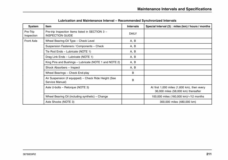
Maintenance Intervals and Specifications
Lubrication and Maintenance Interval – Recommended Synchronized Intervals
System Item Intervals Special Interval (3) : miles (km) / hours / months
Pre-TripInspection
Pre-trip Inspection Items listed in SECTION 3 –INSPECTION GUIDE
DAILY
Wheel Bearing-Oil Type – Check Level A, B
Suspension Fasteners / Components – Check A, B
Tie Rod Ends – Lubricate (NOTE 1) A, B
Drag Link Ends – Lubricate (NOTE 1) A, B
King Pins and Bushings – Lubricate (NOTE 1 and NOTE 2) A, B
Shock Absorbers – Inspect A, B
Wheel Bearings – Check End-play B
Air Suspension (if equipped) – Check Ride Height (SeeService Manual)
B
Axle U-bolts – Retorque (NOTE 3) At first 1,000 miles (1,600 km), then every36,000 miles (58,000 km) thereafter
Wheel Bearing Oil (including synthetic) – Change 100,000 miles (160,000 km)/–/12 months
Front Axle
Axle Shocks (NOTE 3) 300,000 miles (480,000 km)
3878859R2 211

Maintenance Intervals and Specifications
Lubrication and Maintenance Interval – Recommended Synchronized Intervals (cont.)
System Item Intervals Special Interval (3) : miles (km) / hours / months
Suspension Fasteners / Components – Check A, B
Rear Axle Lubricant – Level Checks A, B
Axle Flange Nuts – Retorque B
Air Suspension (if equipped) – Check Ride Height (SeeService Manual)
B
Axle U-bolts – Retorque (NOTE 3) At first 1,000 miles (1,600 km) then every 36,000miles (58,000 km) thereafter.
Rear Axle with Petroleum Oil – Change 100,000(160,000)/–/12
Rear Axle Wheel Ends – Inspect for leaks, lubelevel/condition, and check end play with dial indicator.
100,000(160,000)/–/12 Also at brake lining service.
If wheel end play is found to be outside the 0.001
in. to 0.005 in. specification, or lube condition is
contaminated or low, then perform a full wheel end tear
down. Inspect bearings, spindle, and spindle nuts for
excessive wear and replace as necessary.
Dana – 250,000(400,000 km)/–/36Rear Axle with Synthetic Oil – Change
Meritor – 500,000(800,000)/–/48
Rear Axle
Rear Axle Wheel Ends – Full tear down inspection of allwheel end components, regardless of condition of lube andwheel bearing end play.
500,000 miles (800,000 km)/–/5 Years
Engine Start and Gauge/Warning Indicators – Check A, B
Instrument Readings Proper – Check A, B
ABS Wiring Connections & Sensors – Reseat A, B
Electrical
Alternator-Starter-Battery – Check B
212 3878859R2

Maintenance Intervals and Specifications
Lubrication and Maintenance Interval – Recommended Synchronized Intervals (cont.)
System Item Intervals Special Interval (3) : miles (km) / hours / months
Power Steering Fluid – Check Level A, B
Steering System – Check Tightness A, B
Steering Gear – Lubricate dust seal (if applicable)A, B
ATTN: Install grease slowly, with hand pump,at low pressure. Power grease guns may
blow out dust seal.
Steering Intermediate Shaft U-Joints/Slip Joint – Lubricate A, B
Steering Intermediate Shaft Joint Bolts – Check Tightness 120,000 miles (193,000 km)
Power Steering Fluid – Change 100,000 miles (160,000 km)
Steering
Power Steering Filter – Replace 500,000 miles (800,000 km)
Standard U-Joints and Slip Joint (identified by non-bootedslip joint) – Lubricate (NOTE 3)
15,000 miles (24,000 km)/—/3 monthsDrive Shaft
Optional SPL XL U-Joint – Lubricate 350,000 miles (560,000 km) first lube, 100,000miles (160,000 km) thereafter
Service Brakes Operation – Check A, B
Parking Brakes Operation – Check A, B
Governor Cut-in/Cut-out Pressure – Check A, B
Brake S-Cam Bushing and Slack Adjusters – Lubricate A, B
Air Primary and Secondary Tanks – Drain Water A, B
Shoes-Check for Wear and Drag A, B
Drums, Chambers, Hoses, etc. – Check for wear/damage A, B
Brake Chamber Rod Travel – Check A, B
Air Brakes
Air Dryer Heater & Purge Valve – Check A, B
3878859R2 213

Maintenance Intervals and Specifications
Lubrication and Maintenance Interval – Recommended Synchronized Intervals (cont.)
System Item Intervals Special Interval (3) : miles (km) / hours / months
Air Compressor Discharge Line – Check for Blockage A, B
Brake Shoes (NOTE 3) As Required
Air Brakes(Cont.)
Air Dryer Desiccant – Replace (NOTE 3) AD–9 Model: 250,000 miles (400,000 km)/–/24
Other Models: 125,000 miles (200,000 km)/-/12
Coolant – Check Level A, B
Radiator & CAC Fins – Check for Blockage A, B
Coolant Concentration – Inspection/Adjustment A, B
Fan Clutch – Check A, B
Fan Blade / Shroud – Check Damage/Contact A, B
Coolant AdditiveSee Engine Operation and Maintenance Manual
Extended Life Coolant – Replace See Engine Operation and Maintenance Manual
Cooling Package External Cleaning (NOTE 3) Annually
CoolingSystem
Coolant Filter (if equipped) – Replace See Engine Operation and Maintenance Manual
Engine Oil Level – Check A, B
Engine Belts and Belt Tensioner - Inspect (Replace ifsignificantly deteriorated)
A, B
Air Induction System – Check for Looseness/Leaks A, B
Engine Oil and Oil Filter(s) – Replace See Engine Operation and Maintenance Manual
On-Engine Fuel Filter See Engine Operation and Maintenance Manual
Engine(See EngineOperation andMaintenanceManual forcompletemaintenanceguide)
Engine Air Filter – Replace (NOTE 3) As required by restriction gauge reading/–/1 year
214 3878859R2

Maintenance Intervals and Specifications
Lubrication and Maintenance Interval – Recommended Synchronized Intervals (cont.)
System Item Intervals Special Interval (3) : miles (km) / hours / months
Fuel Sender, Hose Connections – Check for LooseConnectors
A, B
Fuel/ Water Separator – Drain Water/Dirt A, B
Non-Davco Fuel/Water Separator Filter – Replace A, B See Engine Operation and Maintenance Manual
Davco Fuel/Water Separator Filter – Replace See Engine Operation and Maintenance Manual
Fuel System
Fuel Tank(s) – Drain and flush (NOTE 3) 100,000 miles (160,000 km)/–/12
Pipes / Muffler - Inspect for Leakage/Looseness/DamagedInsulation
A, BExhaustSystem
Diesel Particulate Filter (DPF) Cleaning As required by dash warning indicator.
Release Bearing/Shafts/Fork – Lubricate A, BHydraulicClutch Hydraulic Clutch Fluid – Drain and Refill 200,000 miles (322,000 km)/–/2 years
Transmission Fluid – Check Level A, B
Shift Selector / Linkage – Check Function A, B
Neutral Start Switch – Check Function A, B
Transmission Fluid (Synthetic) – Replace (NOTE 3) 500,000 miles (800,000 km) /–/5 years
Transmission Filter – Replace Refer to Transmission Manual
Transmission
Transmission Fluid (Mineral) – Replace B Refer to Transmission Manual
Wear and Condition – Check A, B
Wheel Stud Nuts – Retorque A, B
Tires/Wheels
Spin Balance (NOTE 3) At time of tire mounting and as required
3878859R2 215

Maintenance Intervals and Specifications
Lubrication and Maintenance Interval – Recommended Synchronized Intervals (cont.)
System Item Intervals Special Interval (3) : miles (km) / hours / months
Door Hinges/Latches/Strikers – Lubricate, Check Link (UseMulti-purpose lithium grease or light engine oil. Do Notuse silicone lubricant).
A, B
Windshield Wipers – Inspect A, B
Door Lock Cylinders – Lubricate A, B
Windshield Wipers – Replace 12 months or as required.
CabComponents
Seat Adjuster Slides – Lubricate (NOTE 3) 100,000 miles (160,000 km)
Cowl HVAC Filter – Replace or Clean As requiredHVAC Filters
Sleeper HVAC Filter – Replace or Clean 50,000 miles (80,000 km)
Tire Pressure Check/Tire Wear Check Daily, A, BTires
Low Air Pressure Warning Alarm – Check
A, B
216 3878859R2

Maintenance Intervals and Specifications
Lubrication and Fluids Charts
NOTE: The components requiring lubrication and fluid check andfill diagrams are typical representations.
Lubrication Notes
CAUTION
Unapproved lubricants can cause prematurecomponent failure. Refer to the Lubricants andSealer Specification table for proper lubricants.
• Wipe clean all dirt and debris from grease fittings beforeapplying grease. If the fitting is not cleaned, dirt can bepushed into the component with the grease. Always fillgrease to the point where old grease and contaminants areforced out from the part and only new grease comes out. If afitting does not accept lubrication due to damage or internalstoppage, replace with a new fitting. Remove excess greasefrom fittings and other surfaces after applying grease.
• Some vehicles may have optional remote mounted greasezerks for the clutch cross-shafts. These fittings reduceservice time by providing convenient access to clutchcross-shaft bushing grease zerks. Grease may be appliedthrough two remote mounted grease zerks mounted to thebottom of the transmission bell housing.
Fluid Check and Fill Notes
CAUTION
Use only recommended viscosity engine oil.Refer to the Engine Operation and MaintenanceManual for engine oil specifications.
• Wait five minutes after shutting off the engine beforechecking the oil level. This gives the oil time to drain backto the oil pan.
• Clean all caps and fill plugs prior to removal to prevent dirtand debris from entering system.
• Filling the power steering fluid above the MAX COLD markwhen cold will result in fluid overflow when hot.
• If engine is cold and coolant is above the MIN/ADD line, noadditional coolant is needed. Excessive filling when cold cancause tank to overflow when hot.
• When checking the axle hub fluid level, maintain fluid levelto fill line on hubcap.
• Check the rear axle(s) vent for blockage. Blockage cancause excessive pressure in the axle and create leaks.
3878859R2 217

Maintenance Intervals and Specifications
Components Requiring Lubrication
1. Steering Gear
2. Steering Intermediate Shaft
3. Front S-Cams and Slack Adjusters
4. King Pin Bushings and Thrust Bearings
5. Tie Rod Ends
6. Steering Drag Link Ends
7. Clutch Cross Shafts and Release Bearing
8. Drive Shaft U-joints and Slip Joint
9. Rear S-Cams and Slack Adjusters
10. Fifth Wheel Pivot Points and Top Plate
218 3878859R2

Maintenance Intervals and Specifications
Components Requiring Fluid Check and Fill
1. Engine Oil Dipstick
2. Power Steering Fluid Reservoir
3. Engine Oil Fill Tube
4. Coolant Surge Tank
5. Windshield Washer Fluid Bottle
6. Front Axle Oil-Filled Hubs
7. Transmission Oil Fill/Level Check Plug
8. Drive Axle Oil Fill/Level Check Plug
3878859R2 219

Maintenance Intervals and Specifications
Unit Refill Capacities
Cooling System Refill Capacities
Cooling system refill capacities vary considerably due todifferences in engine models and optional equipment (includingsleeper heater circuit), in addition to the amount of coolantremaining in the system after draining. Total capacity may rangefrom 12 to 15 gallons (45 to 57 Liters). If system has beendrained, fill with a 50/50 mixture of Nitrite-free Shell Rotella®Ultra Extended Life Coolant (ELC) (yellow) concentrate anddemineralized or distilled water, or Nitrite-free Shell Rotella®Ultra ELC 50/50 Premix (yellow). If the system has been flushedwith water or cleaner, a significant amount of the rinse waterwill remain in the system. In this case refilling with a mixturewith a higher percentage (60 to 66%) of coolant concentrateis advised in order to achieve a final mixture closer to 50/50.Fill the system and run the vehicle until the thermostat opens.Before adding any fluid, check the coolant concentration andadd additional water or concentrated undiluted coolant to adjustthe concentration. Run the vehicle and retest for coolant volumelevel (set to “MAX” line) and concentration level.
Crankcase and Oil Filters
For specific engine crankcase capacities, refer to separateEngine Operation and Maintenance Manual provided withvehicle.
Hydraulic Clutch System
Description Fl-Oz Liters
Reservoir Capacity 8.45 .25
System Capacity 16.6 .49
NOTE: Use only approved DOT 3 or DOT 4 brake fluid.
Power Steering Systems
Gear Power Steering Fluid Volume(pints / liters)
TRW PCF60 Steering Gear 8.4 / 3.9
Sheppard HD94 Steering Gear 8.4 / 3.9
220 3878859R2

Maintenance Intervals and Specifications
Transmission
Description Transmission Type Feature Code Pints Liters
Eaton Fuller® 9-Speed (synthetic transmission oil):** Manual 13GPL 28* 13*
Eaton Fuller® 10-Speed (standard transmission oil):** Manual 13GAH; 13GHJ; 13GHK; 13GHL; 13GHN;13GHP; 13GHR; 13GHS; 13GNB
24* 11*
Eaton Fuller® 10-Speed (standard transmission oil):** Manual 13GKZ 24* 11*
Eaton Fuller® 10-Speed (standard transmission oil):** AutoShift 13GRN 24* 11*
Eaton Fuller® 10-Speed (synthetic transmission oil):** AutoShift 13GPN; 13GPP; 13GPR; 13GPS 26* 12*
Eaton Fuller® 10-Speed (synthetic transmission oil):** UltraShift 13GPM; 13GPW 26* 12*
Eaton Fuller® 13-Speed (standard transmission oil):** Manual 13GKJ; 13GRE 28* 13*
Eaton Fuller® 13-Speed (synthetic transmission oil):** Manual 13GJS 28* 13*
Eaton Fuller® 13-Speed (synthetic transmission oil):** UltraShift 13GRX 28* 13*
Eaton Fuller® 15-Speed (standard transmission oil):** Manual 13GHY 28* 13*
Eaton Fuller® 18-Speed (standard transmission oil):** Manual 13GKK; 13GKL; 13GKM; 13GNM 28* 13*
Eaton Fuller® 18-Speed (standard transmission oil):** Manual 13GPV 28* 13*
A variety of transmissions are available for the International® ProStar®+ Series truck. Refer to the Transmission Manual for required capacitiesand transmission oils.
* Approximate refill quantity; less than initial fill as fluids remain in external circuits and transmission cavities.
** Check at operating temperature and top off as required.
3878859R2 221

Maintenance Intervals and Specifications
Rear Axle Unit Refill Capacities
4X2 SINGLE AXLE
Description Feature Code Pints Liters
RS-23-160 14051, 14ARB 39.5 18.7
S23-190 14AHE 37 17.5
RS-23-186 14ARX, 14ARY 47.3 22.4
6X4 TANDEM AXLE Forward Rear
Description Code Pints Liters Pints Liters
RT-40-145,RT-40-145P,RT-40-145A
14GRB,14GRC,14GRN,14GSX,14GUR,14HRN
30.2 14.3 25.8 12.2
DS405P/RS405,DS404/RS404,DS404P/RS404
14GEP,14GER,14GGG,14GGJ
31 14.7 28 13.2
DST41/RST41,DST40/RST40
14GJD,14GJE,14GJP
31 14.7 36 17
MT-40-143-MA-N,MT-40-144-MA-N
14GVB,14GVC,14GWG,14GWH
30.2 14.3 31.4 14.9
D46-170HP/R46-170H,D46-170P/R46-170,
D46-170P/R46-170D,D46-170/R46-170
14GJH,14GJL,14GJM,14GJR
39 18.5 37 17.5
RT-46-160,RT-46-160P
14GRD,14GRP,14GRS,14HRM
29.1 13.8 34.4 16.3
RT-46-164P 14HRW 38.1 18 33.2 15.7
222 3878859R2

Maintenance Intervals and Specifications
Lubricant and Sealer Specifications
Component Component Vendor / Lubrication Type Viscosity Applicable Temperatures
Non-driving Front Axle
Mineral Oil 75W :
75W-80:
75W-90:
75W-140:
80W-90:
80W-140:
85W-140:
-40°F to - 15°F (-40°C to -26°C)
-40°F to 80°F (-40°C to 27°C)
-40°F to 100°F (-40°C to 38°C)
-40°F and above (-40°C and above)
-15°F to 100°F (-26°C to 38°C)
-15°F and above (-26°C and above)
10°F and above (-12°C and above)
Front axlewheel bearingoil
Synthetic – Emgard® 2979 Synthetic Lubricant.
NOTE: Do not mix conventional (mineral based)lubricants with synthetic lubricants.
50W All Temperatures
Front Axle TieRod Ends, DragLink, King Pinsand Bushings
Eaton-Dana® axle, Hendrickson Steertek®,International Multi-Link axle, and Meritor axle:Fleetrite® NLGI #2 Lithium Complex Based Molygrease P/N 991044C2 or equivalent GC/LB NLGI#2 Multi-purpose Lithium Complex grease
NOTE: Eaton-Dana® and Meritor Easy Steeraxles: With chassis load on axle, force greasethrough thrust bearings; then with axle liftedclear of floor, force grease between king pin andbushing surfaces.
3878859R2 223
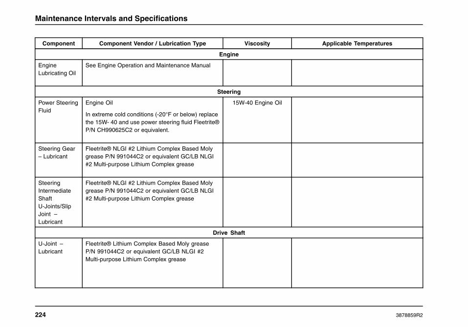
Maintenance Intervals and Specifications
Component Component Vendor / Lubrication Type Viscosity Applicable Temperatures
Engine
EngineLubricating Oil
See Engine Operation and Maintenance Manual
Steering
Power SteeringFluid
Engine Oil
In extreme cold conditions (-20°F or below) replacethe 15W- 40 and use power steering fluid Fleetrite®P/N CH990625C2 or equivalent.
15W-40 Engine Oil
Steering Gear– Lubricant
Fleetrite® NLGI #2 Lithium Complex Based Molygrease P/N 991044C2 or equivalent GC/LB NLGI#2 Multi-purpose Lithium Complex grease
SteeringIntermediateShaftU-Joints/SlipJoint –Lubricant
Fleetrite® NLGI #2 Lithium Complex Based Molygrease P/N 991044C2 or equivalent GC/LB NLGI#2 Multi-purpose Lithium Complex grease
Drive Shaft
U-Joint –Lubricant
Fleetrite® Lithium Complex Based Moly greaseP/N 991044C2 or equivalent GC/LB NLGI #2Multi-purpose Lithium Complex grease
224 3878859R2

Maintenance Intervals and Specifications
Component Component Vendor / Lubrication Type Viscosity Applicable Temperatures
Clutch
ReleaseBearing/Shafts/ Fork– Lubricant
Fleetrite® Lithium Complex Based Moly greaseP/N 991044C2 or equivalent GC/LB NLGI #2Multi-purpose Lithium Complex grease
Cooling System
Extended LifeCoolant
Shell Rotella® Ultra Extended Life Coolant(ELC) – Type III
See Engine Operationand Maintenance
Manual
Heavy Duty– FullyFormulatedCoolant
Type II (Purple) Fleetrite® P/N ZJJSCA5550 See Engine Operationand Maintenance
Manual
Transmission
Mineral Gear Oil API-GL-1 (Rust and OxidationInhibited) Fleetrite® P/N 991061C1
Heavy Duty Engine Oil API – CJ or CI
SAE 90
SAE 80
SAE 50
SAE 40
Above 0 deg. F (-18 deg. C)
Below 0 deg. F (-18 deg. C)
Above 0 deg. F (-18 deg. C)
Below 0 deg. F (-18 deg. C)
TransmissionOil
Synthetic Oil: Emgard® 2979 Synthetic Lubricant 50W All Temperatures
3878859R2 225

Maintenance Intervals and Specifications
Component Component Vendor / Lubrication Type Viscosity Applicable Temperatures
Rear Axle
Mineral Oil – Gear oil meeting MIL-PRF-2105E,API Mete GL-5
75W
75W-80
75W-90
75W-140
80W-90
80W-140
85W-140
-40°F to - 15°F (-40°C to -26°C)
-40°F to 80°F (-40°C to 27°C)
-40°F to 100°F (-40°C to 38°C)
-40°F and above (-40°C and above)
-15°F to 100°F (-26°C to 38°C)
-15°F and above (-26°C and above)
10°F and above (-12°C and above)
Rear DriveAxle(s)
Synthetic – Emgard® 2837 and Emgard®FE Synthetic Lubricant.
NOTE: Do not mix conventional (mineralbases) lube with synthetic oil.
75W-90 All Temperatures
Electrical
Terminals– LubricantSealing Grease
Fleetrite® 472141-C1
Connectors– DielectricGrease
NYOGEL® 760 G
226 3878859R2

Maintenance Intervals and Specifications
Torque Specifications
U-BOLT NUT TORQUE CHART
TorqueFeature Code Rear Suspension Capacity and Type
lbf - ft N • m
14SAN 23,500-lb (10,659 kg) Capacity, RR, Springs, Single, Vari-Rate 260-300 353-407
14SAU 20,000-lb (9072 kg) Capacity, RR, Springs Multileaf with Single Torque Rod 258-295 350-400
14SAW 23,000-lb (10,433 kg) Capacity, RR, Springs Multileaf with Single Torque Rod 260-300 353-407
20,000-lb (9072 kg) Capacity, International Air Suspension (IROS) for axles14ADN, 14ADP,14AJC,14AJE, 14ATP, and 14ATR.
260-300 353-40714TBJ
20,000-lb (9072 kg) Capacity, International Air Suspension (IROS) for all otheraxles.
370-400 502-542
14UNL, 14UNM, 14UNN,14UNS, 14UNT, and 14UNU
40,000-lb (18,144 kg) Capacity, International Air Suspension (IROS) 370-400 502-542
NOTE: For all other vendor supplied suspensions, refer to vendor’s website for proper torque specifications.
TorqueFeature Code Front Suspension Capacity and Type
lbf - ft N • m
3ADC 12,000-lb (5443 kg) Capacity, Parabolic Taper Leaf 260-300 353-407
3ADD 14,000-lb (6350 kg) Capacity, Parabolic Taper Leaf 260-300 353-407
3AGV 12,000-lb (5443 kg) Capacity, Monoleaf (Hendrickson Softek) 260-300 353-407
3AHM 12,350-lb (5602 kg) Capacity, Monoleaf (Hendrickson Softek) 260-300 353-407
3878859R2 227

Maintenance Intervals and Specifications
TorqueFeature Code Front Suspension Capacity and Type
lbf - ft N • m
3AHN 12,350-lb (5602 kg) Capacity, Parabolic Taper Leaf 260-300 353-407
NOTE: For all other vendor supplied suspensions, refer to vendor’s website for proper torque specifications.
DISC WHEEL NUT TORQUE CHART
TorqueLug NutSize
Lug NutType
SocketSize lbf - ft N • m
22 mm 2 piece 33 mm 450 - 500 610 - 678
NOTE: Do not use lubrication on dry threads. Where excessivecorrosion exists, a light coat of lubricant on the first three threadsof stud is permitted. Keep lubricant away from nut and rim clampcontact surfaces
Fuse Charts
The following fuse illustrations represent typical fuse panellayouts. The actual vehicle fuse panels will vary depending onthe vehicle options. Refer to the chart on rear side of fuse cover.
228 3878859R2

Maintenance Intervals and Specifications
Typical Interior Fuse Panel Layout
3878859R2 229

Maintenance Intervals and Specifications
Typical Luggage Compartment Fuse Panel Layout
230 3878859R2

Maintenance Intervals and Specifications
ProStar®+ Series Light Information
Lamp Description Bulb P/N
Sleeper Dome Lamp F15T8/CW
Day Cab Dome Lamp 212
Cab Dome Lamp 577
Accent Lamps 577
Under Bunk Lamp 577
Cab Floor Lamp W5W
Sleeper Floor Lamp W5W
Sleeper Reading Lamp 912
Wardrobe Cabinet Lamp 7575
Cab Map Lamp 912
Door Lamps W5W
Clearance/Marker Lamp (LED) 168
Stop/Turn/Tail Lamp (LED) International® ProStar®+ Series: Truck Lite Super 40 (Truck Lite Super44 Optional)
Back Up Lamp (LED) Truck Lite Super 40
Work Light 4411
3878859R2 231
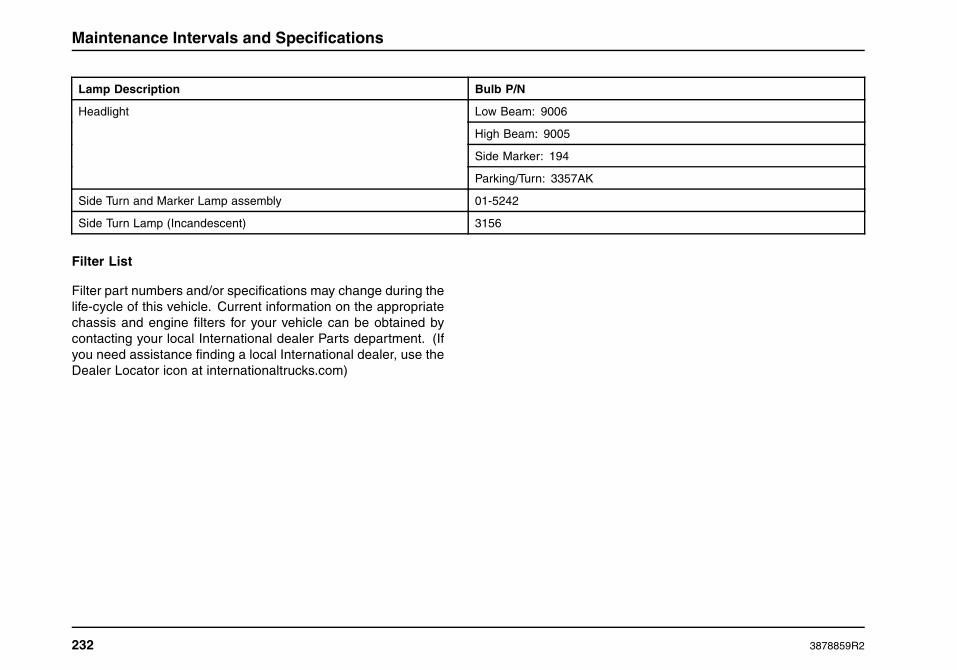
Maintenance Intervals and Specifications
Lamp Description Bulb P/N
Low Beam: 9006
High Beam: 9005
Side Marker: 194
Headlight
Parking/Turn: 3357AK
Side Turn and Marker Lamp assembly 01-5242
Side Turn Lamp (Incandescent) 3156
Filter List
Filter part numbers and/or specifications may change during thelife-cycle of this vehicle. Current information on the appropriatechassis and engine filters for your vehicle can be obtained bycontacting your local International dealer Parts department. (Ifyou need assistance finding a local International dealer, use theDealer Locator icon at internationaltrucks.com)
232 3878859R2

Customer Assistance
SECTION 9 — CUSTOMER ASSISTANCE
Service Information
The continued premium performance of this International®chassis can best be assured through proper servicing. This canbe accomplished in several ways.
International Truck Dealers … Your local InternationalTruck dealer provides an excellent resource – through hisknowledgeable, experienced, and well equipped service staff –to handle all your maintenance, repair, and replacement work.
Service Publications … Those persons who are properlytrained technicians with the facilities, equipment, tools, safetyinstructions and know-how to properly and safely service abus, medium duty and/or heavy duty chassis can purchasethe appropriate service manual sections applicable to specificvehicle components or areas of this International® vehicle.Engine diagnostic manuals and engine service manuals for allcurrent International® diesel engines are also available to thesetrained persons for purchase. Information on the purchase ofavailable service publications for this chassis can be found onthe internationaltrucks.com Web site, or by contacting your localInternational dealer.
These service resources are also available via the Internet, byan annual subscription to the Fleet ISIS® Web site, or via theiService DVD. Information on the Fleet ISIS Web site’s content,
availability, and fee structure can be obtained by contactingyour local International Truck dealer or, in the case of a NationalAccount, an International Fleet Service Manager.
The iService DVD contains all currently available chassis andcomponent service information, including TSI letters, ElectricalCircuit Diagrams, Electrical System Troubleshooting and othertechnical information, for virtually all International® models andMaxxForce® engines.
International Truck Warranty Program
Standard Warranty • Optional Service Contracts • CustomService Contracts • Performance PM® Service
The International Truck Warranty Program provides Internationalcustomers with a better choice when it comes to StandardWarranty and Service Contract Coverage. The StandardWarranty is the first tier of the International Truck WarrantyProgram. It provides the foundation for all extended coverages.
Vehicle Coverage, Towing, Engine and Engine Electronics,Major Component, and Pre-Packaged System Componentprotection can be obtained under the International WarrantyProgram through Optional Service Contracts.
3878859R2 233

Customer Assistance
Custom Service Contracts, the most flexible aspect of theInternational Truck Warranty Program, can provide extendedprotection that is specifically tailored to meet each customer’sspecific requirements.
Finally, through Performance PM® Service, customers canobtain a comprehensive preventative maintenance programdesigned to ensure consistency in pricing and the level ofservice received.
ADVANTAGES of International Truck Warranties
• Extends warranty protection to specified length andcomponent coverage to suit individual needs
• Honored at over 1,000 International Truck Dealer locationsin North America
• Stabilized and predictable maintenance costs
• Increased owner confidence and peace of mind
• Improved resale value on your vehicle – International TruckWarranties may be transferable for a nominal fee. Contactthe Service Contract Center 1-800-346-4429 option 1 fortransferability
• Most coverage is 100% parts and labor with NODEDUCTIBLES .
• Customized warranty programs are offered to suit yourneeds - your specification - your vocation
• International, North America’s leader in truck manufacturing,is also North America’s leader in warranty value
• Optional Service Contracts, Custom Service Contracts, andPerformance PM® Service, designed to assure the lowestpossible cost of ownership, are also available
• Optional Service Contracts have been pre-packaged to fitmost common applications
• Custom Service Contracts are designed to meet yourindividual needs
HOW TO OBTAIN International Truck Warranties
• Standard Warranty: Your new International® vehicle isautomatically registered in the International Truck Warrantysystem at the time of delivery. No further action on yourpart is required.
• Optional Service Contracts, Custom Service Contracts,or Performance PM® Service: These programs are soldexclusively through your International dealer. The vehiclemust also have coverage remaining under the StandardWarranty. For extended warranty purchases between, 181through 365 days from DTU and <100,000 miles (160,000km) an additional fee will be assessed. If you would like thepredictable cost of ownership and peace of mind providedby the International Truck Warranty Program, please contactyour International dealer today!
234 3878859R2

Index
SECTION 10 — INDEX
AABS Connections and Sensors. . . . . . . . . . . . . . . . . . . . . . . . . . . . . . . . .182ABS Operation. . . . . . . . . . . . . . . . . . . . . . . . . . . . . . . . . . . . . . . . . . . . . . . . . . . .158ABS Self Check. . . . . . . . . . . . . . . . . . . . . . . . . . . . . . . . . . . . . . . . . . . . . . . . . . .159Accent Light Dimmer Switch. . . . . . . . . . . . . . . . . . . . . . . . . . . . . . . . . . . . . .99Accent Light Switch. . . . . . . . . . . . . . . . . . . . . . . . . . . . . . . . . . . . . . . . . . . . . . . .99Accent Lights. . . . . . . . . . . . . . . . . . . . . . . . . . . . . . . . . . . . . . . . . . . . . . . . . . . . . . .97Accessory Feed Connections. . . . . . . . . . . . . . . . . . . . . . . . . . . . . . . . . . .186Additional Unsafe Practices. . . . . . . . . . . . . . . . . . . . . . . . . . . . . . . . . . . . .137Adjustable Belts. . . . . . . . . . . . . . . . . . . . . . . . . . . . . . . . . . . . . . . . . . . . . . . . . . .103Adjustable Steering Column. . . . . . . . . . . . . . . . . . . . . . . . . . . . . . . . . . . . .129After the Engine Starts. . . . . . . . . . . . . . . . . . . . . . . . . . . . . . . . . . . . . . . . . . .124Air Brakes. . . . . . . . . . . . . . . . . . . . . . . . . . . . . . . . . . . . . . . . . . . . . . . . . . .152, 179
Air Gauge, Low Air Pressure Beeper and WarningIndicator. . . . . . . . . . . . . . . . . . . . . . . . . . . . . . . . . . . . . . . . . . . . . . . . . . . . . . .153
Brake Application. . . . . . . . . . . . . . . . . . . . . . . . . . . . . . . . . . . . . . . . . . . . . .154Inspection and Adjustment. . . . . . . . . . . . . . . . . . . . . . . . . . . . . . . . . . . .179Reservoir Moisture Draining. . . . . . . . . . . . . . . . . . . . . . . . . . . . . . . . . .153
Air Cleaner Element Service. . . . . . . . . . . . . . . . . . . . . . . . . . . . . . . . . . . .189Air Compressor Cycling. . . . . . . . . . . . . . . . . . . . . . . . . . . . . . . . . . . . . . . . . .135Air Conditioning. . . . . . . . . . . . . . . . . . . . . . . . . . . . . . . . . . . . . . . . . . . . . . . . . . . .88Air Conditioning Service Checks. . . . . . . . . . . . . . . . . . . . . . . . . . . . . . . .174
Front Access HVAC Filter. . . . . . . . . . . . . . . . . . . . . . . . . . . . . . . . . . . . .175HVAC Filters. . . . . . . . . . . . . . . . . . . . . . . . . . . . . . . . . . . . . . . . . . . . . . . . . . . .174Recirculation Filters. . . . . . . . . . . . . . . . . . . . . . . . . . . . . . . . . . . . . . . . . . . .175Side Access HVAC Filter. . . . . . . . . . . . . . . . . . . . . . . . . . . . . . . . . . . . . .174Sleeper HVAC Filter. . . . . . . . . . . . . . . . . . . . . . . . . . . . . . . . . . . . . . . . . . .176
Air Dryer. . . . . . . . . . . . . . . . . . . . . . . . . . . . . . . . . . . . . . . . . . . . . . . . . . . . .155, 180Desiccant Filter. . . . . . . . . . . . . . . . . . . . . . . . . . . . . . . . . . . . . . . . . . . . . . . . .181Heater. . . . . . . . . . . . . . . . . . . . . . . . . . . . . . . . . . . . . . . . . . . . . . . . . . . . . . . . . . .181
A (CONT.)
Air Dryer (cont.)Purge Valve. . . . . . . . . . . . . . . . . . . . . . . . . . . . . . . . . . . . . . . . . . . . . . . . . . . . .181
Air Gauge, Low Air Pressure Beeper and WarningIndicator. . . . . . . . . . . . . . . . . . . . . . . . . . . . . . . . . . . . . . . . . . . . . . . . . . . . . . . . . .153
Air Induction System.. . . . . . . . . . . . . . . . . . . . . . . . . . . . . . . . . . . . . . . . . . . .187Air Intake System.. . . . . . . . . . . . . . . . . . . . . . . . . . . . . . . . . . . . . . . . . . . . . . . .196Air Reservoir/Tanks Moisture Draining. . . . . . . . . . . . . . . . . . . . . . . . .181Air Restriction Gauge. . . . . . . . . . . . . . . . . . . . . . . . . . . . . . . . . . . . . . . . . . . .188Air Suspension System Faults. . . . . . . . . . . . . . . . . . . . . . . . . . . . . . . . . .151Airline Cabinets. . . . . . . . . . . . . . . . . . . . . . . . . . . . . . . . . . . . . . . . . . . . . . . . . . .114Alignment. . . . . . . . . . . . . . . . . . . . . . . . . . . . . . . . . . . . . . . . . . . . . . . . . . . . . . . . . .177Alternator. . . . . . . . . . . . . . . . . . . . . . . . . . . . . . . . . . . . . . . . . . . . . . . . . . . . . . . . . .130Antifreeze. . . . . . . . . . . . . . . . . . . . . . . . . . . . . . . . . . . . . . . . . . . . . . . . . . . . . . . . . .194Antilock Brake System (ABS). . . . . . . . . . . . . . . . . . . . . . . . . . . . . . . . . . .158
ABS Operation. . . . . . . . . . . . . . . . . . . . . . . . . . . . . . . . . . . . . . . . . . . . . . . . .158ABS Self Check. . . . . . . . . . . . . . . . . . . . . . . . . . . . . . . . . . . . . . . . . . . . . . . .159Antilock Driving Tips. . . . . . . . . . . . . . . . . . . . . . . . . . . . . . . . . . . . . . . . . . .159
Antilock Driving Tips. . . . . . . . . . . . . . . . . . . . . . . . . . . . . . . . . . . . . . . . . . . . .159Assistance Guide. . . . . . . . . . . . . . . . . . . . . . . . . . . . . . . . . . . . . . . . . . . . . . . . . . . .1ATC OFF ROAD or MUD/SNOW Switch. . . . . . . . . . . . . . . . . . . . . . .160ATC System Check. . . . . . . . . . . . . . . . . . . . . . . . . . . . . . . . . . . . . . . . . . . . . . .160Automatic Door Lock Function. . . . . . . . . . . . . . . . . . . . . . . . . . . . . . . . . . . .91Automatic Traction Control (ATC) System.. . . . . . . . . . . . . . . . . . . . .159
ATC OFF ROAD or MUD/SNOW Switch. . . . . . . . . . . . . . . . . . . .160ATC System Check. . . . . . . . . . . . . . . . . . . . . . . . . . . . . . . . . . . . . . . . . . . .160Stability Control Systems – Bendix® RSP/WABCORSC/Bendix ESP.. . . . . . . . . . . . . . . . . . . . . . . . . . . . . . . . . . . . . . . . . . . .160
Available Models. . . . . . . . . . . . . . . . . . . . . . . . . . . . . . . . . . . . . . . . . . . . . . . . . . . . .9Axles. . . . . . . . . . . . . . . . . . . . . . . . . . . . . . . . . . . . . . . . . . . . . . . . . . . . . . . . . . . . . . .176
3878859R2 235

Index
A (CONT.)
Axles (cont.)Front Axle. . . . . . . . . . . . . . . . . . . . . . . . . . . . . . . . . . . . . . . . . . . . . . . . . . . . . . .176
Alignment. . . . . . . . . . . . . . . . . . . . . . . . . . . . . . . . . . . . . . . . . . . . . . . . . . . .177Inspection and Lubrication. . . . . . . . . . . . . . . . . . . . . . . . . . . . . . . . .176Normal Maintenance. . . . . . . . . . . . . . . . . . . . . . . . . . . . . . . . . . . . . . . .177
Locking Differential. . . . . . . . . . . . . . . . . . . . . . . . . . . . . . . . . . . . . . . . . . . .178Rear Axle. . . . . . . . . . . . . . . . . . . . . . . . . . . . . . . . . . . . . . . . . . . . . . . . . . . . . . .177
Inspection and Lubrication. . . . . . . . . . . . . . . . . . . . . . . . . . . . . . . . .177
BBase Display. . . . . . . . . . . . . . . . . . . . . . . . . . . . . . . . . . . . . . . . . . . . . . . . . . . . . . . .89Batteries. . . . . . . . . . . . . . . . . . . . . . . . . . . . . . . . . . . . . . . . . . . . . . . . . . . . . . . . . . .184Battery. . . . . . . . . . . . . . . . . . . . . . . . . . . . . . . . . . . . . . . . . . . . . . . . . . . . . . . . . . . . .130Battery Cables. . . . . . . . . . . . . . . . . . . . . . . . . . . . . . . . . . . . . . . . . . . . . . . . . . . .185BATTERY ON Indicator. . . . . . . . . . . . . . . . . . . . . . . . . . . . . . . . . . . . . . . . . .131Bobtail Proportioning System.. . . . . . . . . . . . . . . . . . . . . . . . . . . . . . . . . .157Body. . . . . . . . . . . . . . . . . . . . . . . . . . . . . . . . . . . . . . . . . . . . . . . . . . . . . . . . . . . . . . .196Brake Application. . . . . . . . . . . . . . . . . . . . . . . . . . . . . . . . . . . . . . . . . . . . . . . . .154Brakes. . . . . . . . . . . . . . . . . . . . . . . . . . . . . . . . . . . . . . . . . . . . . . . . . . . . . . .151, 178
ABS Connections and Sensors. . . . . . . . . . . . . . . . . . . . . . . . . . . . . .182Air Brakes. . . . . . . . . . . . . . . . . . . . . . . . . . . . . . . . . . . . . . . . . . . . . . . . .152, 179
Air Gauge, Low Air Pressure Beeper and WarningIndicator. . . . . . . . . . . . . . . . . . . . . . . . . . . . . . . . . . . . . . . . . . . . . . . . . . . . .153
Brake Application. . . . . . . . . . . . . . . . . . . . . . . . . . . . . . . . . . . . . . . . . . . .154Inspection and Adjustment. . . . . . . . . . . . . . . . . . . . . . . . . . . . . . . . .179Reservoir Moisture Draining. . . . . . . . . . . . . . . . . . . . . . . . . . . . . . .153
Air Dryer. . . . . . . . . . . . . . . . . . . . . . . . . . . . . . . . . . . . . . . . . . . . . . . . . .155, 180Desiccant Filter. . . . . . . . . . . . . . . . . . . . . . . . . . . . . . . . . . . . . . . . . . . . . .181Heater. . . . . . . . . . . . . . . . . . . . . . . . . . . . . . . . . . . . . . . . . . . . . . . . . . . . . . . .181Purge Valve. . . . . . . . . . . . . . . . . . . . . . . . . . . . . . . . . . . . . . . . . . . . . . . . . .181
Air Reservoir/Tanks Moisture Draining. . . . . . . . . . . . . . . . . . . . . .181
B (CONT.)
Brakes (cont.)Antilock Brake System (ABS). . . . . . . . . . . . . . . . . . . . . . . . . . . . . . . . .158
ABS Operation. . . . . . . . . . . . . . . . . . . . . . . . . . . . . . . . . . . . . . . . . . . . . . .158ABS Self Check. . . . . . . . . . . . . . . . . . . . . . . . . . . . . . . . . . . . . . . . . . . . .159Antilock Driving Tips. . . . . . . . . . . . . . . . . . . . . . . . . . . . . . . . . . . . . . . .159
Bobtail Proportioning System.. . . . . . . . . . . . . . . . . . . . . . . . . . . . . . . .157Downhill Operation. . . . . . . . . . . . . . . . . . . . . . . . . . . . . . . . . . . . . . . . . . . . .152Parking Brake. . . . . . . . . . . . . . . . . . . . . . . . . . . . . . . . . . . . . . . . . . . . . . . . . .154
Parking Brake Alarm. . . . . . . . . . . . . . . . . . . . . . . . . . . . . . . . . . . . . . . .155Parking Brake Reset. . . . . . . . . . . . . . . . . . . . . . . . . . . . . . . . . . . . . . . .155
Parking Brake Indicator. . . . . . . . . . . . . . . . . . . . . . . . . . . . . . . . . . . . . . .157Trailer Air Supply and Parking Brake Modular Controls. . . .156Trailer Brake Hand Control. . . . . . . . . . . . . . . . . . . . . . . . . . . . . . . . . . . .155
Bright Metal Care. . . . . . . . . . . . . . . . . . . . . . . . . . . . . . . . . . . . . . . . . . . . . . . . .182Bunk Restraint System.. . . . . . . . . . . . . . . . . . . . . . . . . . . . . . . . . . . . . . . . . .103
Adjustable Belts. . . . . . . . . . . . . . . . . . . . . . . . . . . . . . . . . . . . . . . . . . . . . . . .103Restraint Webbing System.. . . . . . . . . . . . . . . . . . . . . . . . . . . . . . . . . . .103
CCab.. . . . . . . . . . . . . . . . . . . . . . . . . . . . . . . . . . . . . . . . . . . . . . . . . . . . . . . . . . . . . . . .182
Care of Vehicle. . . . . . . . . . . . . . . . . . . . . . . . . . . . . . . . . . . . . . . . . . . . . . . . .182Bright Metal Care. . . . . . . . . . . . . . . . . . . . . . . . . . . . . . . . . . . . . . . . . . . .182Exposed Rubber and Unpainted Plastic Parts. . . . . . . . . . .182Upholstery Care. . . . . . . . . . . . . . . . . . . . . . . . . . . . . . . . . . . . . . . . . . . . .182Washing and Waxing. . . . . . . . . . . . . . . . . . . . . . . . . . . . . . . . . . . . . . .182
Cab Controls. . . . . . . . . . . . . . . . . . . . . . . . . . . . . . . . . . . . . . . . . . . . . . . . . . . . . .118Cab Doors and Locks. . . . . . . . . . . . . . . . . . . . . . . . . . . . . . . . . . . . . . . . . . . . . .90Cab Entry and Exit. . . . . . . . . . . . . . . . . . . . . . . . . . . . . . . . . . . . . . . . . . . . . . . . .18Cab Interior Inspection. . . . . . . . . . . . . . . . . . . . . . . . . . . . . . . . . . . . . . . . . . . .41Cabinets. . . . . . . . . . . . . . . . . . . . . . . . . . . . . . . . . . . . . . . . . . . . . . . . . . . . . . . . . . .110
Airline Cabinets. . . . . . . . . . . . . . . . . . . . . . . . . . . . . . . . . . . . . . . . . . . . . . . .114
236 3878859R2

Index
C (CONT.)
Cabinets (cont.)Dresser Cabinet. . . . . . . . . . . . . . . . . . . . . . . . . . . . . . . . . . . . . . . . . . . . . . . .111Horizontal Refrigerator. . . . . . . . . . . . . . . . . . . . . . . . . . . . . . . . . . . . . . . .111Rear Wardrobe Cabinet. . . . . . . . . . . . . . . . . . . . . . . . . . . . . . . . . . . . . . .113Refrigerator Cabinet. . . . . . . . . . . . . . . . . . . . . . . . . . . . . . . . . . . . . . . . . . .110Tower Wardrobe Cabinet. . . . . . . . . . . . . . . . . . . . . . . . . . . . . . . . . . . . . .112
Cabinets/Storage. . . . . . . . . . . . . . . . . . . . . . . . . . . . . . . . . . . . . . . . . . . . . . . . .109Canadian Registered Vehicles. . . . . . . . . . . . . . . . . . . . . . . . . . . . . . . . . . . . .5Care of Seat Belts. . . . . . . . . . . . . . . . . . . . . . . . . . . . . . . . . . . . . . . . . . . . . . . .120Care of Vehicle. . . . . . . . . . . . . . . . . . . . . . . . . . . . . . . . . . . . . . . . . . . . . . . . . . . .182
Bright Metal Care. . . . . . . . . . . . . . . . . . . . . . . . . . . . . . . . . . . . . . . . . . . . . .182Exposed Rubber and Unpainted Plastic Parts. . . . . . . . . . . . . .182Upholstery Care. . . . . . . . . . . . . . . . . . . . . . . . . . . . . . . . . . . . . . . . . . . . . . . .182Washing and Waxing. . . . . . . . . . . . . . . . . . . . . . . . . . . . . . . . . . . . . . . . . .182
Cautions and Warnings. . . . . . . . . . . . . . . . . . . . . . . . . . . . . . . . . . . . . . . . . . . . .1Center Dash Panel/Wing Panel. . . . . . . . . . . . . . . . . . . . . . . . . . . . . . . . . . .81
Climate Control. . . . . . . . . . . . . . . . . . . . . . . . . . . . . . . . . . . . . . . . . . . . . . . . . .86Air Conditioning. . . . . . . . . . . . . . . . . . . . . . . . . . . . . . . . . . . . . . . . . . . . . . .88Dehumidification. . . . . . . . . . . . . . . . . . . . . . . . . . . . . . . . . . . . . . . . . . . . . .89
Gauges. . . . . . . . . . . . . . . . . . . . . . . . . . . . . . . . . . . . . . . . . . . . . . . . . . . . . . . . . . .82Switches. . . . . . . . . . . . . . . . . . . . . . . . . . . . . . . . . . . . . . . . . . . . . . . . . . . . . . . . . .82
Certified Clean Idle. . . . . . . . . . . . . . . . . . . . . . . . . . . . . . . . . . . . . . . . . . . . . . .134Charge Air Cooler. . . . . . . . . . . . . . . . . . . . . . . . . . . . . . . . . . . . . . . . . . . . . . . .132Charge Air Cooler And Radiator Core Inspection AndCleaning. . . . . . . . . . . . . . . . . . . . . . . . . . . . . . . . . . . . . . . . . . . . . . . . . . . . . . . . . .192Inspection and Cleaning. . . . . . . . . . . . . . . . . . . . . . . . . . . . . . . . . . . . . .192
Chassis Lubrication. . . . . . . . . . . . . . . . . . . . . . . . . . . . . . . . . . . . . . . . . . . . . .173Chassis Skirts. . . . . . . . . . . . . . . . . . . . . . . . . . . . . . . . . . . . . . . . . . . . . . . . . . . . . .21
Extended Chassis Skirts. . . . . . . . . . . . . . . . . . . . . . . . . . . . . . . . . . . . . . .22Installation. . . . . . . . . . . . . . . . . . . . . . . . . . . . . . . . . . . . . . . . . . . . . . . . . . . . . . . .22Removal. . . . . . . . . . . . . . . . . . . . . . . . . . . . . . . . . . . . . . . . . . . . . . . . . . . . . . . . . .21
C (CONT.)Checking Inflation. . . . . . . . . . . . . . . . . . . . . . . . . . . . . . . . . . . . . . . . . . . . . . . .201Circuit Breakers, Fuses and Fusible Links. . . . . . . . . . . . . . . . . . . . .131Cleaning. . . . . . . . . . . . . . . . . . . . . . . . . . . . . . . . . . . . . . . . . . . . . . . . . . . . . . . . . . .197Climate Control. . . . . . . . . . . . . . . . . . . . . . . . . . . . . . . . . . . . . . . . . . . . . . . . . . . . .86
Air Conditioning. . . . . . . . . . . . . . . . . . . . . . . . . . . . . . . . . . . . . . . . . . . . . . . . . .88Dehumidification. . . . . . . . . . . . . . . . . . . . . . . . . . . . . . . . . . . . . . . . . . . . . . . . .89
Clutch. . . . . . . . . . . . . . . . . . . . . . . . . . . . . . . . . . . . . . . . . . . . . . . . . . . . . . . . . . . . . .183Hydraulic Clutch. . . . . . . . . . . . . . . . . . . . . . . . . . . . . . . . . . . . . . . . . . . . . . . .183Pedal Free Travel. . . . . . . . . . . . . . . . . . . . . . . . . . . . . . . . . . . . . . . . . . . . . .183
Clutch Brake. . . . . . . . . . . . . . . . . . . . . . . . . . . . . . . . . . . . . . . . . . . . . . . . . . . . . .148Clutch Precautions. . . . . . . . . . . . . . . . . . . . . . . . . . . . . . . . . . . . . . . . . . . . . . .145Cold Weather. . . . . . . . . . . . . . . . . . . . . . . . . . . . . . . . . . . . . . . . . . . . . . . . . . . . .125
Cold Weather Operation. . . . . . . . . . . . . . . . . . . . . . . . . . . . . . . . . . . . . .126Cold Weather Starting. . . . . . . . . . . . . . . . . . . . . . . . . . . . . . . . . . . . . . . . .125Engine Idle Shutdown Timer (Optional). . . . . . . . . . . . . . . . . . . . .127Engine Idling. . . . . . . . . . . . . . . . . . . . . . . . . . . . . . . . . . . . . . . . . . . . . . . . . . . .126Winter Front Usage. . . . . . . . . . . . . . . . . . . . . . . . . . . . . . . . . . . . . . . . . . . .127
Cold Weather Operation. . . . . . . . . . . . . . . . . . . . . . . . . . . . . . . . . . . . . . . . .126Cold Weather Starting. . . . . . . . . . . . . . . . . . . . . . . . . . . . . . . . . . . . . . . . . . .125Compass Declination Zone Set Procedure. . . . . . . . . . . . . . . . . . . . . .57Compass Directional Calibration Procedure. . . . . . . . . . . . . . . . . . . .60Component Code Numbers. . . . . . . . . . . . . . . . . . . . . . . . . . . . . . . . . . . . . . . .2
Line Set Ticket. . . . . . . . . . . . . . . . . . . . . . . . . . . . . . . . . . . . . . . . . . . . . . . . . . . .2Components Requiring Fluid Check and Fill. . . . . . . . . . . . . . . . . .219Components Requiring Lubrication. . . . . . . . . . . . . . . . . . . . . . . . . . . . .218Connecting/Disconnecting a Trailer to a Vehicle with AirSuspension. . . . . . . . . . . . . . . . . . . . . . . . . . . . . . . . . . . . . . . . . . . . . . . . . . . . . .166
Convenience Features. . . . . . . . . . . . . . . . . . . . . . . . . . . . . . . . . . . . . . . . . . .115Floor Covering. . . . . . . . . . . . . . . . . . . . . . . . . . . . . . . . . . . . . . . . . . . . . . . . . .115Power Inverter. . . . . . . . . . . . . . . . . . . . . . . . . . . . . . . . . . . . . . . . . . . . . . . . . .115Power Sockets. . . . . . . . . . . . . . . . . . . . . . . . . . . . . . . . . . . . . . . . . . . . . . . . .115
3878859R2 237

Index
C (CONT.)
Convenience Features (cont.)Sleeper Curtain. . . . . . . . . . . . . . . . . . . . . . . . . . . . . . . . . . . . . . . . . . . . . . . .115Sleeper Fan. . . . . . . . . . . . . . . . . . . . . . . . . . . . . . . . . . . . . . . . . . . . . . . . . . . . .115Speakers. . . . . . . . . . . . . . . . . . . . . . . . . . . . . . . . . . . . . . . . . . . . . . . . . . . . . . . .115Television Mount. . . . . . . . . . . . . . . . . . . . . . . . . . . . . . . . . . . . . . . . . . . . . . .115
Coolant and Optional Coolant Filter. . . . . . . . . . . . . . . . . . . . . . . . . . . .194Coolant Concentration Freeze Point. . . . . . . . . . . . . . . . . . . . . . . . . . . .194Coolant Level Check. . . . . . . . . . . . . . . . . . . . . . . . . . . . . . . . . . . . . . . . . . . . .192Cooling System.. . . . . . . . . . . . . . . . . . . . . . . . . . . . . . . . . . . . . . . . . . . . . . . . . .192
Antifreeze. . . . . . . . . . . . . . . . . . . . . . . . . . . . . . . . . . . . . . . . . . . . . . . . . . . . . . .194Coolant and Optional Coolant Filter. . . . . . . . . . . . . . . . . . . . . . . . .194Coolant Concentration Freeze Point. . . . . . . . . . . . . . . . . . . . . . . . .194Coolant Level Check. . . . . . . . . . . . . . . . . . . . . . . . . . . . . . . . . . . . . . . . . . .192Fan Clutch. . . . . . . . . . . . . . . . . . . . . . . . . . . . . . . . . . . . . . . . . . . . . . . . . . . . . .194Filling Instructions. . . . . . . . . . . . . . . . . . . . . . . . . . . . . . . . . . . . . . . . . . . . . .192
Cooling System Refill Capacities. . . . . . . . . . . . . . . . . . . . . . . . . . . . . . .220Courtesy Lights. . . . . . . . . . . . . . . . . . . . . . . . . . . . . . . . . . . . . . . . . . . . . . . . . . . .76Crankcase and Oil Filters. . . . . . . . . . . . . . . . . . . . . . . . . . . . . . . . . . . . . . . .220Crankcase Ventilation Filter. . . . . . . . . . . . . . . . . . . . . . . . . . . . . . . . . . . . .195Cruise Control. . . . . . . . . . . . . . . . . . . . . . . . . . . . . . . . . . . . . . . . . . . . . . . . . . . . . .78Customer Security Guide for International Trucks. . . . . . . . . . . . . . .6
DDash Components. . . . . . . . . . . . . . . . . . . . . . . . . . . . . . . . . . . . . . . . . . . . . . . . .44Daytime Running Lights (DRL). . . . . . . . . . . . . . . . . . . . . . . . . . . . . . . . . . .75Dehumidification. . . . . . . . . . . . . . . . . . . . . . . . . . . . . . . . . . . . . . . . . . . . . . . . . . .89Desiccant Filter. . . . . . . . . . . . . . . . . . . . . . . . . . . . . . . . . . . . . . . . . . . . . . . . . . .181Diesel Particulate Filter (DPF). . . . . . . . . . . . . . . . . . . . . . . . . . . . . . . . . .196
Cleaning. . . . . . . . . . . . . . . . . . . . . . . . . . . . . . . . . . . . . . . . . . . . . . . . . . . . . . . .197Regeneration. . . . . . . . . . . . . . . . . . . . . . . . . . . . . . . . . . . . . . . . . . . . . . . . . . .196
Direct Drive Warning Indicators. . . . . . . . . . . . . . . . . . . . . . . . . . . . . . . . . .54
D (CONT.)Disc Wheel Nut Torque Chart. . . . . . . . . . . . . . . . . . . . . . . . . . . . . . . . . . .228Dome Light. . . . . . . . . . . . . . . . . . . . . . . . . . . . . . . . . . . . . . . . . . . . . . . . . . . . . . . . .97Dome Lighting. . . . . . . . . . . . . . . . . . . . . . . . . . . . . . . . . . . . . . . . . . . . . . . . . . . . . .76Door and Window Controls. . . . . . . . . . . . . . . . . . . . . . . . . . . . . . . . . . . . . . .90
Door Lock/Unlock. . . . . . . . . . . . . . . . . . . . . . . . . . . . . . . . . . . . . . . . . . . . . . .90Automatic Door Lock Function. . . . . . . . . . . . . . . . . . . . . . . . . . . . . .91Cab Doors and Locks. . . . . . . . . . . . . . . . . . . . . . . . . . . . . . . . . . . . . . . .90Lock/Unlock From Interior. . . . . . . . . . . . . . . . . . . . . . . . . . . . . . . . . . . .91Remote Keyless Entry Operation (Optional). . . . . . . . . . . . . . .90
Driver/Passenger Windows.. . . . . . . . . . . . . . . . . . . . . . . . . . . . . . . . . . . .91Manual Operation. . . . . . . . . . . . . . . . . . . . . . . . . . . . . . . . . . . . . . . . . . . . .91Mirror Controls. . . . . . . . . . . . . . . . . . . . . . . . . . . . . . . . . . . . . . . . . . . . . . . .92Power Operation. . . . . . . . . . . . . . . . . . . . . . . . . . . . . . . . . . . . . . . . . . . . . .92Vent Window.. . . . . . . . . . . . . . . . . . . . . . . . . . . . . . . . . . . . . . . . . . . . . . . . .92Window Lockout Function. . . . . . . . . . . . . . . . . . . . . . . . . . . . . . . . . . .92
Door Lock/Unlock. . . . . . . . . . . . . . . . . . . . . . . . . . . . . . . . . . . . . . . . . . . . . . . . . .90Automatic Door Lock Function. . . . . . . . . . . . . . . . . . . . . . . . . . . . . . . . .91Cab Doors and Locks. . . . . . . . . . . . . . . . . . . . . . . . . . . . . . . . . . . . . . . . . . .90Lock/Unlock From Interior. . . . . . . . . . . . . . . . . . . . . . . . . . . . . . . . . . . . . .91
Locking the Door. . . . . . . . . . . . . . . . . . . . . . . . . . . . . . . . . . . . . . . . . . . . . .91Unlocking the Door. . . . . . . . . . . . . . . . . . . . . . . . . . . . . . . . . . . . . . . . . . .91
Remote Keyless Entry Operation (Optional). . . . . . . . . . . . . . . . .90Double Clutch Procedures. . . . . . . . . . . . . . . . . . . . . . . . . . . . . . . . . . . . . . .145Downhill Operation. . . . . . . . . . . . . . . . . . . . . . . . . . . . . . . . . . . . . . . . . . . . . . .152Dresser Cabinet. . . . . . . . . . . . . . . . . . . . . . . . . . . . . . . . . . . . . . . . . . . . . . . . . .111Drive Shafts. . . . . . . . . . . . . . . . . . . . . . . . . . . . . . . . . . . . . . . . . . . . . . . . . . . . . . .197Driver and Passenger Side. . . . . . . . . . . . . . . . . . . . . . . . . . . . . . . . . . . . . . .21Driver Controlled Differential Lock. . . . . . . . . . . . . . . . . . . . . . . . . . . . . .150Driver Reward. . . . . . . . . . . . . . . . . . . . . . . . . . . . . . . . . . . . . . . . . . . . . . . . . . . . . .93Driver/Passenger Windows. . . . . . . . . . . . . . . . . . . . . . . . . . . . . . . . . . . . . . .91
Manual Operation. . . . . . . . . . . . . . . . . . . . . . . . . . . . . . . . . . . . . . . . . . . . . . .91
238 3878859R2

Index
D (CONT.)
Driver/Passenger Windows (cont.)Mirror Controls. . . . . . . . . . . . . . . . . . . . . . . . . . . . . . . . . . . . . . . . . . . . . . . . . . .92Power Operation. . . . . . . . . . . . . . . . . . . . . . . . . . . . . . . . . . . . . . . . . . . . . . . . .92Vent Window.. . . . . . . . . . . . . . . . . . . . . . . . . . . . . . . . . . . . . . . . . . . . . . . . . . . .92Window Lockout Function. . . . . . . . . . . . . . . . . . . . . . . . . . . . . . . . . . . . . .92
Dual Tires Matching. . . . . . . . . . . . . . . . . . . . . . . . . . . . . . . . . . . . . . . . . . . . . .203Dual Tires Mixing. . . . . . . . . . . . . . . . . . . . . . . . . . . . . . . . . . . . . . . . . . . . . . . . .203
EEaton AutoShift® Transmissions (Optional). . . . . . . . . . . . . . . . . . .146Eaton UltraShift® Transmissions (Optional). . . . . . . . . . . . . . . . . . .148Eaton VORAD Collision Warning System (Optional). . . . . . . . . . .93
Driver Reward. . . . . . . . . . . . . . . . . . . . . . . . . . . . . . . . . . . . . . . . . . . . . . . . . . .93System Description. . . . . . . . . . . . . . . . . . . . . . . . . . . . . . . . . . . . . . . . . . . . .93
Electrical. . . . . . . . . . . . . . . . . . . . . . . . . . . . . . . . . . . . . . . . . . . . . . . . . . . . .130, 184Accessory Feed Connections. . . . . . . . . . . . . . . . . . . . . . . . . . . . . . . .186Alternator. . . . . . . . . . . . . . . . . . . . . . . . . . . . . . . . . . . . . . . . . . . . . . . . . . . . . . .130Batteries. . . . . . . . . . . . . . . . . . . . . . . . . . . . . . . . . . . . . . . . . . . . . . . . . . . . . . . .184Battery. . . . . . . . . . . . . . . . . . . . . . . . . . . . . . . . . . . . . . . . . . . . . . . . . . . . . . . . . .130Battery Cables. . . . . . . . . . . . . . . . . . . . . . . . . . . . . . . . . . . . . . . . . . . . . . . . .185BATTERY ON Indicator. . . . . . . . . . . . . . . . . . . . . . . . . . . . . . . . . . . . . . .131Circuit Breakers, Fuses and Fusible Links. . . . . . . . . . . . . . . . . .131Electrical Charging and Starting System Test. . . . . . . . . . . . . .185Electrical Load Control and Shedding (ELCS). . . . . . . . . . . . . .132Fuses and Relays. . . . . . . . . . . . . . . . . . . . . . . . . . . . . . . . . . . . . . . . . . . . . .186Terminal Inspection-Cleaning-Corrosion Protection. . . . . . . .185
Electrical Charging and Starting System Test. . . . . . . . . . . . . . . . .185Electrical Load Control and Shedding (ELCS). . . . . . . . . . . . . . . .132Electrical System.. . . . . . . . . . . . . . . . . . . . . . . . . . . . . . . . . . . . . . . . . . . . . . . . . .43Electronic Climate Controller. . . . . . . . . . . . . . . . . . . . . . . . . . . . . . . . . . . .100Electronic Engine Controller. . . . . . . . . . . . . . . . . . . . . . . . . . . . . . . . . . . . .133
E (CONT.)Electronic Vehicle Monitoring. . . . . . . . . . . . . . . . . . . . . . . . . . . . . . . . . . . . .89
Base Display. . . . . . . . . . . . . . . . . . . . . . . . . . . . . . . . . . . . . . . . . . . . . . . . . . . . .89Premium Display. . . . . . . . . . . . . . . . . . . . . . . . . . . . . . . . . . . . . . . . . . . . . . . .89
Emergency Starting. . . . . . . . . . . . . . . . . . . . . . . . . . . . . . . . . . . . . . . . . . . . . .124Emission Control Systems.. . . . . . . . . . . . . . . . . . . . . . . . . . . . . . . . . . . . . . . . .5Engaging the Clutch. . . . . . . . . . . . . . . . . . . . . . . . . . . . . . . . . . . . . . . . . . . . . .143Engine. . . . . . . . . . . . . . . . . . . . . . . . . . . . . . . . . . . . . . . . . . . . . . . . . . . . . . .132, 186
Air Cleaner Element Service. . . . . . . . . . . . . . . . . . . . . . . . . . . . . . . . .189Air Compressor Cycling. . . . . . . . . . . . . . . . . . . . . . . . . . . . . . . . . . . . . . .135Air Induction System.. . . . . . . . . . . . . . . . . . . . . . . . . . . . . . . . . . . . . . . . . .187Air Restriction Gauge.. . . . . . . . . . . . . . . . . . . . . . . . . . . . . . . . . . . . . . . . .188Certified Clean Idle. . . . . . . . . . . . . . . . . . . . . . . . . . . . . . . . . . . . . . . . . . . .134Charge Air Cooler. . . . . . . . . . . . . . . . . . . . . . . . . . . . . . . . . . . . . . . . . . . . . .132Charge Air Cooler And Radiator Core Inspection AndCleaning. . . . . . . . . . . . . . . . . . . . . . . . . . . . . . . . . . . . . . . . . . . . . . . . . . . . . . .192Inspection and Cleaning. . . . . . . . . . . . . . . . . . . . . . . . . . . . . . . . . . . .192
Cooling System.. . . . . . . . . . . . . . . . . . . . . . . . . . . . . . . . . . . . . . . . . . . . . . .192Antifreeze. . . . . . . . . . . . . . . . . . . . . . . . . . . . . . . . . . . . . . . . . . . . . . . . . . . .194Coolant and Optional Coolant Filter. . . . . . . . . . . . . . . . . . . . . . .194Coolant Concentration Freeze Point. . . . . . . . . . . . . . . . . . . . . .194Coolant Level Check. . . . . . . . . . . . . . . . . . . . . . . . . . . . . . . . . . . . . . . .192Fan Clutch. . . . . . . . . . . . . . . . . . . . . . . . . . . . . . . . . . . . . . . . . . . . . . . . . . .194Filling Instructions. . . . . . . . . . . . . . . . . . . . . . . . . . . . . . . . . . . . . . . . . . .192
Crankcase Ventilation Filter. . . . . . . . . . . . . . . . . . . . . . . . . . . . . . . . . . .195Electronic Engine Controller. . . . . . . . . . . . . . . . . . . . . . . . . . . . . . . . . .133Engine Brake. . . . . . . . . . . . . . . . . . . . . . . . . . . . . . . . . . . . . . . . . . . . . . . . . . .133Engine fluids and contaminated material. . . . . . . . . . . . . . . . . . . .187Engine Oil. . . . . . . . . . . . . . . . . . . . . . . . . . . . . . . . . . . . . . . . . . . . . . . . . . . . . . .136Engine Performance Problems.. . . . . . . . . . . . . . . . . . . . . . . . . . . . . .136Fuel System.. . . . . . . . . . . . . . . . . . . . . . . . . . . . . . . . . . . . . . . . . . . . . . . . . . .195
Fuel Tank Draining and Cleaning. . . . . . . . . . . . . . . . . . . . . . . . . .195
3878859R2 239

Index
E (CONT.)
Engine (cont.)MaxxForce® 11, 13 and 15 Engine Brake With EatonAutoShift®/UltraShift® Transmissions Special DriverInstructions. . . . . . . . . . . . . . . . . . . . . . . . . . . . . . . . . . . . . . . . . . . . . . . . . . . .133
MaxxForce® Engine Features. . . . . . . . . . . . . . . . . . . . . . . . . . . . . . . .134Scheduled Maintenance. . . . . . . . . . . . . . . . . . . . . . . . . . . . . . . . . . . . . .187Self Diagnostics. . . . . . . . . . . . . . . . . . . . . . . . . . . . . . . . . . . . . . . . . . . . . . . .134Troubleshooting. . . . . . . . . . . . . . . . . . . . . . . . . . . . . . . . . . . . . . . . . . . . . . . .191
Engine Brake. . . . . . . . . . . . . . . . . . . . . . . . . . . . . . . . . . . . . . . . . . . . . . . . . . . . . .133Engine Control Switch. . . . . . . . . . . . . . . . . . . . . . . . . . . . . . . . . . . . . . . . . . . . .99Engine fluids and contaminated material. . . . . . . . . . . . . . . . . . . . . .187Engine Idle Shutdown Timer (Optional). . . . . . . . . . . . . . . . . . . . . . . .127Engine Idling. . . . . . . . . . . . . . . . . . . . . . . . . . . . . . . . . . . . . . . . . . . . . . . . . . . . . .126Engine Noise Shields/Blankets. . . . . . . . . . . . . . . . . . . . . . . . . . . . . . . . .196Engine Oil. . . . . . . . . . . . . . . . . . . . . . . . . . . . . . . . . . . . . . . . . . . . . . . . . . . . . . . . .136Engine Performance Problems. . . . . . . . . . . . . . . . . . . . . . . . . . . . . . . . . .136Engine Serial Number. . . . . . . . . . . . . . . . . . . . . . . . . . . . . . . . . . . . . . . . . . . . .13Engine Shutdown.. . . . . . . . . . . . . . . . . . . . . . . . . . . . . . . . . . . . . . . . . . . . . . . .124Engine Starting. . . . . . . . . . . . . . . . . . . . . . . . . . . . . . . . . . . . . . . . . . . . . . . . . . .123Entering The Upper Bunk. . . . . . . . . . . . . . . . . . . . . . . . . . . . . . . . . . . . . . . .107Exhaust Diesel Particulate Filter Regeneration. . . . . . . . . . . . . . .139
Parked Regeneration Procedure. . . . . . . . . . . . . . . . . . . . . . . . . . . . .141Regeneration Inhibit Switch. . . . . . . . . . . . . . . . . . . . . . . . . . . . . . . . . . .141Three-Position Regeneration Inhibit Switch. . . . . . . . . . . . . . . . .142Two-Position Regeneration Inhibit Switch. . . . . . . . . . . . . . . . . . .142
Exhaust System.. . . . . . . . . . . . . . . . . . . . . . . . . . . . . . . . . . . . . . . . . . . . . . . . .196Exiting The Upper Bunk. . . . . . . . . . . . . . . . . . . . . . . . . . . . . . . . . . . . . . . . . .108Exposed Rubber and Unpainted Plastic Parts. . . . . . . . . . . . . . . .182Extended Chassis Skirts. . . . . . . . . . . . . . . . . . . . . . . . . . . . . . . . . . . . . . . . . .22Exterior Components. . . . . . . . . . . . . . . . . . . . . . . . . . . . . . . . . . . . . . . . . . . . . .14Exterior Lights Check. . . . . . . . . . . . . . . . . . . . . . . . . . . . . . . . . . . . . . . . . . . . . .24
E (CONT.)Exterior Noise Emissions. . . . . . . . . . . . . . . . . . . . . . . . . . . . . . . . . . . . . . . . . . .4
FFan Clutch. . . . . . . . . . . . . . . . . . . . . . . . . . . . . . . . . . . . . . . . . . . . . . . . . . . . . . . . .194Feature Codes. . . . . . . . . . . . . . . . . . . . . . . . . . . . . . . . . . . . . . . . . . . . . . . . . . . . .12Fifth Wheel and Coupling Area. . . . . . . . . . . . . . . . . . . . . . . . . . . . . . . . . . .40Fifth Wheel Jaw Monitoring. . . . . . . . . . . . . . . . . . . . . . . . . . . . . . . . . . . . . .169Fifth Wheel Jaw Unlock Control. . . . . . . . . . . . . . . . . . . . . . . . . . . . . . . . .168Fifth Wheel Operation. . . . . . . . . . . . . . . . . . . . . . . . . . . . . . . . . . . . . . . . . . . .166
Fifth Wheel Jaw Monitoring. . . . . . . . . . . . . . . . . . . . . . . . . . . . . . . . . . .169Fifth Wheel Jaw Unlock Control. . . . . . . . . . . . . . . . . . . . . . . . . . . . . .168Fifth Wheel Slide Switch (Optional). . . . . . . . . . . . . . . . . . . . . . . . . .167Hook-Up. . . . . . . . . . . . . . . . . . . . . . . . . . . . . . . . . . . . . . . . . . . . . . . . . . . . . . . .167Un-Hook. . . . . . . . . . . . . . . . . . . . . . . . . . . . . . . . . . . . . . . . . . . . . . . . . . . . . . . .168
Fifth Wheel Slide Switch (Optional). . . . . . . . . . . . . . . . . . . . . . . . . . . . .167Filling Instructions. . . . . . . . . . . . . . . . . . . . . . . . . . . . . . . . . . . . . . . . . . . . . . . .192Filter List. . . . . . . . . . . . . . . . . . . . . . . . . . . . . . . . . . . . . . . . . . . . . . . . . . . . . . . . . . .232Floor Covering. . . . . . . . . . . . . . . . . . . . . . . . . . . . . . . . . . . . . . . . . . . . . . . . . . . .115Floor Lights. . . . . . . . . . . . . . . . . . . . . . . . . . . . . . . . . . . . . . . . . . . . . . . . . . . . . . . . .97Frame.. . . . . . . . . . . . . . . . . . . . . . . . . . . . . . . . . . . . . . . . . . . . . . . . . . . . . . . . . . . . .195Front Access HVAC Filter. . . . . . . . . . . . . . . . . . . . . . . . . . . . . . . . . . . . . . . .175Front Axle. . . . . . . . . . . . . . . . . . . . . . . . . . . . . . . . . . . . . . . . . . . . . . . . . . . . . . . . . .176
Alignment. . . . . . . . . . . . . . . . . . . . . . . . . . . . . . . . . . . . . . . . . . . . . . . . . . . . . . .177Inspection and Lubrication. . . . . . . . . . . . . . . . . . . . . . . . . . . . . . . . . . . .176Normal Maintenance. . . . . . . . . . . . . . . . . . . . . . . . . . . . . . . . . . . . . . . . . .177
Front of Tractor. . . . . . . . . . . . . . . . . . . . . . . . . . . . . . . . . . . . . . . . . . . . . . . . . . . . .29Front Suspension. . . . . . . . . . . . . . . . . . . . . . . . . . . . . . . . . . . . . . . . . . . . . . . . .197Fuel. . . . . . . . . . . . . . . . . . . . . . . . . . . . . . . . . . . . . . . . . . . . . . . . . . . . . . . . . . . . . . . .137
Additional Unsafe Practices. . . . . . . . . . . . . . . . . . . . . . . . . . . . . . . . . . .137Fuel and Lubricant Additives. . . . . . . . . . . . . . . . . . . . . . . . . . . . . . . . .137Fueling Precautions. . . . . . . . . . . . . . . . . . . . . . . . . . . . . . . . . . . . . . . . . . .138
240 3878859R2

Index
F (CONT.)
Fuel (cont.)Fueling Procedures. . . . . . . . . . . . . . . . . . . . . . . . . . . . . . . . . . . . . . . . . . . .137Hazards of Diesel Fuel/Gasoline Blends. . . . . . . . . . . . . . . . . . . .137Reserve Fuel. . . . . . . . . . . . . . . . . . . . . . . . . . . . . . . . . . . . . . . . . . . . . . . . . . .138Ultra Low Sulfur Diesel Fuel Requirements. . . . . . . . . . . . . . . . .137Unacceptable Fuel Blends. . . . . . . . . . . . . . . . . . . . . . . . . . . . . . . . . . . .137
Fuel and Lubricant Additives. . . . . . . . . . . . . . . . . . . . . . . . . . . . . . . . . . . .137Fuel System.. . . . . . . . . . . . . . . . . . . . . . . . . . . . . . . . . . . . . . . . . . . . . . . . . . . . . .195
Fuel Tank Draining and Cleaning. . . . . . . . . . . . . . . . . . . . . . . . . . . .195Fuel Tank Draining and Cleaning. . . . . . . . . . . . . . . . . . . . . . . . . . . . . . .195Fueling Precautions. . . . . . . . . . . . . . . . . . . . . . . . . . . . . . . . . . . . . . . . . . . . . .138Fueling Procedures. . . . . . . . . . . . . . . . . . . . . . . . . . . . . . . . . . . . . . . . . . . . . . .137Fuse Charts. . . . . . . . . . . . . . . . . . . . . . . . . . . . . . . . . . . . . . . . . . . . . . . . . . . . . . .228
Filter List. . . . . . . . . . . . . . . . . . . . . . . . . . . . . . . . . . . . . . . . . . . . . . . . . . . . . . . .232ProStar®+ Series Light Information. . . . . . . . . . . . . . . . . . . . . . . . . . .231Typical Interior Fuse Panel Layout. . . . . . . . . . . . . . . . . . . . . . . . . . .229Typical Luggage Compartment Fuse Panel Layout. . . . . . . .230
Fuses and Relays. . . . . . . . . . . . . . . . . . . . . . . . . . . . . . . . . . . . . . . . . . . . . . . .186
GGauges. . . . . . . . . . . . . . . . . . . . . . . . . . . . . . . . . . . . . . . . . . . . . . . . . . . . . . . . .50, 82General Text and Warning Messages. . . . . . . . . . . . . . . . . . . . . . . . . . . .56
HHazards of Diesel Fuel/Gasoline Blends. . . . . . . . . . . . . . . . . . . . . . .137Headlights. . . . . . . . . . . . . . . . . . . . . . . . . . . . . . . . . . . . . . . . . . . . . . . . . . . . . . . . . .75Heater. . . . . . . . . . . . . . . . . . . . . . . . . . . . . . . . . . . . . . . . . . . . . . . . . . . . . . . . . . . . . .181High Restriction Reading Table. . . . . . . . . . . . . . . . . . . . . . . . . . . . . . . . .191Hood.. . . . . . . . . . . . . . . . . . . . . . . . . . . . . . . . . . . . . . . . . . . . . . . . . . . . . . . . . . . . . . . .18
Lowering the Hood. . . . . . . . . . . . . . . . . . . . . . . . . . . . . . . . . . . . . . . . . . . . . .19Raising the Hood.. . . . . . . . . . . . . . . . . . . . . . . . . . . . . . . . . . . . . . . . . . . . . . .18
H (CONT.)Hook-Up.. . . . . . . . . . . . . . . . . . . . . . . . . . . . . . . . . . . . . . . . . . . . . . . . . . . . . . . . . .167Horizontal Refrigerator. . . . . . . . . . . . . . . . . . . . . . . . . . . . . . . . . . . . . . . . . . .111Hot Weather Operation. . . . . . . . . . . . . . . . . . . . . . . . . . . . . . . . . . . . . . . . . .127Hub-Piloted Wheel Installation Procedures. . . . . . . . . . . . . . . . . . . .206HVAC Filters. . . . . . . . . . . . . . . . . . . . . . . . . . . . . . . . . . . . . . . . . . . . . . . . . . . . . .174Hydraulic Clutch. . . . . . . . . . . . . . . . . . . . . . . . . . . . . . . . . . . . . . . . . . . . . . . . . .183Hydraulic Clutch Actuation System.. . . . . . . . . . . . . . . . . . . . . . . . . . . .144Hydraulic Clutch System.. . . . . . . . . . . . . . . . . . . . . . . . . . . . . . . . . . . . . . . .220
IInspection. . . . . . . . . . . . . . . . . . . . . . . . . . . . . . . . . . . . . . . . . . . . . . . . . . . . . . . . .202Inspection and Adjustment. . . . . . . . . . . . . . . . . . . . . . . . . . . . . . . . . . . . . .179Inspection and Cleaning. . . . . . . . . . . . . . . . . . . . . . . . . . . . . . . . . . . . . . . . .192Inspection and Lubrication. . . . . . . . . . . . . . . . . . . . . . . . . . . . . . . . .176–177Installation. . . . . . . . . . . . . . . . . . . . . . . . . . . . . . . . . . . . . . . . . . . . . . . . . . . . . . . . . .22Installing Axle Shafts. . . . . . . . . . . . . . . . . . . . . . . . . . . . . . . . . . . . . . . . . . . . .165Instructions for Proper Maintenance. . . . . . . . . . . . . . . . . . . . . . . . . . . .196Instrument Panel Gauge Cluster. . . . . . . . . . . . . . . . . . . . . . . . . . . . . . . . .46
Direct Drive Warning Indicators. . . . . . . . . . . . . . . . . . . . . . . . . . . . . . . .54Gauges. . . . . . . . . . . . . . . . . . . . . . . . . . . . . . . . . . . . . . . . . . . . . . . . . . . . . . . . . . .50Instrument Panel Gauge Cluster Alarms.. . . . . . . . . . . . . . . . . . . . .52Integral Digital Display. . . . . . . . . . . . . . . . . . . . . . . . . . . . . . . . . . . . . . . . . .54
General Text and Warning Messages. . . . . . . . . . . . . . . . . . . . . .56Integral Digital Display Detailed Information. . . . . . . . . . . . . . . . . .62Optional Instrument panel gauge cluster Compass CalibrationProcedure. . . . . . . . . . . . . . . . . . . . . . . . . . . . . . . . . . . . . . . . . . . . . . . . . . . . . . .57Compass Declination Zone Set Procedure. . . . . . . . . . . . . . . .57Compass Directional Calibration Procedure. . . . . . . . . . . . . . .60
Switches. . . . . . . . . . . . . . . . . . . . . . . . . . . . . . . . . . . . . . . . . . . . . . . . . . . . . . . . . .75Courtesy Lights. . . . . . . . . . . . . . . . . . . . . . . . . . . . . . . . . . . . . . . . . . . . . . .76Daytime Running Lights (DRL). . . . . . . . . . . . . . . . . . . . . . . . . . . . . .75
3878859R2 241
Index
I (CONT.)
Instrument Panel Gauge Cluster (cont.)Dome Lighting. . . . . . . . . . . . . . . . . . . . . . . . . . . . . . . . . . . . . . . . . . . . . . . . .76Headlights. . . . . . . . . . . . . . . . . . . . . . . . . . . . . . . . . . . . . . . . . . . . . . . . . . . . .75Lights On With Wipers. . . . . . . . . . . . . . . . . . . . . . . . . . . . . . . . . . . . . . .75Panel Lighting. . . . . . . . . . . . . . . . . . . . . . . . . . . . . . . . . . . . . . . . . . . . . . . . .75Park Lights. . . . . . . . . . . . . . . . . . . . . . . . . . . . . . . . . . . . . . . . . . . . . . . . . . . .75
Warning Indicators. . . . . . . . . . . . . . . . . . . . . . . . . . . . . . . . . . . . . . . . . . . . . .48Instrument Panel Gauge Cluster Alarms. . . . . . . . . . . . . . . . . . . . . . . .52Integral Digital Display. . . . . . . . . . . . . . . . . . . . . . . . . . . . . . . . . . . . . . . . . . . . .54
General Text and Warning Messages. . . . . . . . . . . . . . . . . . . . . . . . .56Integral Digital Display Detailed Information. . . . . . . . . . . . . . . . . . . .62
Outside Temperature and Compass Displays (Optional). . . .74Outside Temperature Reading. . . . . . . . . . . . . . . . . . . . . . . . . . . . . . . . .74Quadrant 1: Informational Displays. . . . . . . . . . . . . . . . . . . . . . . . . . .62Quadrant 2: Text and Warning Messages. . . . . . . . . . . . . . . . . . . .67Quadrant 3: Display Messages. . . . . . . . . . . . . . . . . . . . . . . . . . . . . . . .74Quadrant 4: Transmission Gear Displays. . . . . . . . . . . . . . . . . . . . .75Warning Messages. . . . . . . . . . . . . . . . . . . . . . . . . . . . . . . . . . . . . . . . . . . . . .74
International Truck Warranty Program.. . . . . . . . . . . . . . . . . . . . . . . . .233Introduction
Electrical System.. . . . . . . . . . . . . . . . . . . . . . . . . . . . . . . . . . . . . . . . . . . . . . .43Main Features. . . . . . . . . . . . . . . . . . . . . . . . . . . . . . . . . . . . . . . . . . . . . . . . . . .95
Irregular Wear. . . . . . . . . . . . . . . . . . . . . . . . . . . . . . . . . . . . . . . . . . . . . . . . . . . . .205
LLeft Engine Compartment. . . . . . . . . . . . . . . . . . . . . . . . . . . . . . . . . . . . . . . . .26Left Front of Tractor. . . . . . . . . . . . . . . . . . . . . . . . . . . . . . . . . . . . . . . . . . . . . . . .27Left Rear of Tractor. . . . . . . . . . . . . . . . . . . . . . . . . . . . . . . . . . . . . . . . . . . . . . . .38Left Side Cab Area. . . . . . . . . . . . . . . . . . . . . . . . . . . . . . . . . . . . . . . . . . . . . . . . .25Lighting. . . . . . . . . . . . . . . . . . . . . . . . . . . . . . . . . . . . . . . . . . . . . . . . . . . . . . . . . . . . . .97
L (CONT.)
Lighting (cont.)Accent Lights. . . . . . . . . . . . . . . . . . . . . . . . . . . . . . . . . . . . . . . . . . . . . . . . . . . .97Dome Light. . . . . . . . . . . . . . . . . . . . . . . . . . . . . . . . . . . . . . . . . . . . . . . . . . . . . . .97Floor Lights. . . . . . . . . . . . . . . . . . . . . . . . . . . . . . . . . . . . . . . . . . . . . . . . . . . . . .97Reading Lights. . . . . . . . . . . . . . . . . . . . . . . . . . . . . . . . . . . . . . . . . . . . . . . . . . .97
Lights On With Wipers. . . . . . . . . . . . . . . . . . . . . . . . . . . . . . . . . . . . . . . . . . . . .75Line Set Ticket. . . . . . . . . . . . . . . . . . . . . . . . . . . . . . . . . . . . . . . . . . . . . . . . . . .2, 13Loads. . . . . . . . . . . . . . . . . . . . . . . . . . . . . . . . . . . . . . . . . . . . . . . . . . . . . . . . . . . . . .203Lock/Unlock From Interior. . . . . . . . . . . . . . . . . . . . . . . . . . . . . . . . . . . . . . . . .91
Locking the Door. . . . . . . . . . . . . . . . . . . . . . . . . . . . . . . . . . . . . . . . . . . . . . . .91Unlocking the Door. . . . . . . . . . . . . . . . . . . . . . . . . . . . . . . . . . . . . . . . . . . . . .91
Locking Differential. . . . . . . . . . . . . . . . . . . . . . . . . . . . . . . . . . . . . . . . . . . . . . .178Locking or Limited Slip Differentials. . . . . . . . . . . . . . . . . . . . . . . . . . . .148Locking the Door. . . . . . . . . . . . . . . . . . . . . . . . . . . . . . . . . . . . . . . . . . . . . . . . . . .91Lower Bunk. . . . . . . . . . . . . . . . . . . . . . . . . . . . . . . . . . . . . . . . . . . . . . . . . . . . . . . .105Lowering the Hood. . . . . . . . . . . . . . . . . . . . . . . . . . . . . . . . . . . . . . . . . . . . . . . . .19Lowering the Tilt-Away Bumper. . . . . . . . . . . . . . . . . . . . . . . . . . . . . . . . . .20Lubricant and Sealer Specifications. . . . . . . . . . . . . . . . . . . . . . . . . . . .223Lubrication and Fluids Charts. . . . . . . . . . . . . . . . . . . . . . . . . . . . . . . . . . .217
Components Requiring Fluid Check and Fill. . . . . . . . . . . . . . . .219Components Requiring Lubrication. . . . . . . . . . . . . . . . . . . . . . . . . .218
Lubrication and Maintenance Interval – RecommendedSynchronized Intervals Table. . . . . . . . . . . . . . . . . . . . . . . . . . . . . . . . . .211
Lubrication and Maintenance Interval Chart Notes. . . . . . . . . . .210Lubrication and Maintenance Interval Chart Symbols Key. . .210Lubrication and Maintenance Intervals . . . . . . . . . . . . . . . . . . . . . . . .209
Maintenance Intervals. . . . . . . . . . . . . . . . . . . . . . . . . . . . . . . . . . . . . . . . .209Lubrication Points. . . . . . . . . . . . . . . . . . . . . . . . . . . . . . . . . . . . . . . . . . . . . . . . .199Luggage Box Access. . . . . . . . . . . . . . . . . . . . . . . . . . . . . . . . . . . . . . . . . . . . . .21
Driver and Passenger Side. . . . . . . . . . . . . . . . . . . . . . . . . . . . . . . . . . . . .21
242 3878859R2

Index
MMain Features. . . . . . . . . . . . . . . . . . . . . . . . . . . . . . . . . . . . . . . . . . . . . . . . . . . . . .95Maintenance Guidelines. . . . . . . . . . . . . . . . . . . . . . . . . . . . . . . . . . . . . . . . .171Maintenance Intervals. . . . . . . . . . . . . . . . . . . . . . . . . . . . . . . . . . . . . . . . . . . .209
Lubrication and Maintenance Interval – RecommendedSynchronized Intervals Table. . . . . . . . . . . . . . . . . . . . . . . . . . . . . . . .211
Lubrication and Maintenance Interval Chart Notes. . . . . . . .210Lubrication and Maintenance Interval Chart SymbolsKey. . . . . . . . . . . . . . . . . . . . . . . . . . . . . . . . . . . . . . . . . . . . . . . . . . . . . . . . . . . . .210
Maintenance Record – Noise Control. . . . . . . . . . . . . . . . . . . . . . . . . . . . .5Manual Climate Controls. . . . . . . . . . . . . . . . . . . . . . . . . . . . . . . . . . . . . . . . .100Manual Operation. . . . . . . . . . . . . . . . . . . . . . . . . . . . . . . . . . . . . . . . . . . . . . . . . .91Manual Transmissions. . . . . . . . . . . . . . . . . . . . . . . . . . . . . . . . . . . . . . . . . . .142MaxxForce® 11, 13 and 15 Engine Brake With EatonAutoShift®/UltraShift® Transmissions Special DriverInstructions. . . . . . . . . . . . . . . . . . . . . . . . . . . . . . . . . . . . . . . . . . . . . . . . . . . . . . .133
MaxxForce® Engine Features. . . . . . . . . . . . . . . . . . . . . . . . . . . . . . . . . .134Mirror Controls. . . . . . . . . . . . . . . . . . . . . . . . . . . . . . . . . . . . . . . . . . . . . . . . . . . . .92
NNo Restriction Reading Table. . . . . . . . . . . . . . . . . . . . . . . . . . . . . . . . . . .191Noise Emissions – Exterior. . . . . . . . . . . . . . . . . . . . . . . . . . . . . . . . . . . . . .196
Air Intake System.. . . . . . . . . . . . . . . . . . . . . . . . . . . . . . . . . . . . . . . . . . . . .196Body. . . . . . . . . . . . . . . . . . . . . . . . . . . . . . . . . . . . . . . . . . . . . . . . . . . . . . . . . . . . .196Engine Noise Shields/Blankets. . . . . . . . . . . . . . . . . . . . . . . . . . . . . . .196Exhaust System.. . . . . . . . . . . . . . . . . . . . . . . . . . . . . . . . . . . . . . . . . . . . . . .196Instructions for Proper Maintenance. . . . . . . . . . . . . . . . . . . . . . . . .196
Normal Maintenance. . . . . . . . . . . . . . . . . . . . . . . . . . . . . . . . . . . . . . . . . . . . .177
OOperating Instructions. . . . . . . . . . . . . . . . . . . . . . . . . . . . . . . . . . . . . . . . . . . .128
Electrical. . . . . . . . . . . . . . . . . . . . . . . . . . . . . . . . . . . . . . . . . . . . . . . . . . . . . . . .130
O (CONT.)
Operating Instructions (cont.)Alternator. . . . . . . . . . . . . . . . . . . . . . . . . . . . . . . . . . . . . . . . . . . . . . . . . . . . .130Battery. . . . . . . . . . . . . . . . . . . . . . . . . . . . . . . . . . . . . . . . . . . . . . . . . . . . . . . .130BATTERY ON Indicator. . . . . . . . . . . . . . . . . . . . . . . . . . . . . . . . . . . . .131Circuit Breakers, Fuses and Fusible Links. . . . . . . . . . . . . . .131Electrical Load Control and Shedding (ELCS). . . . . . . . . . .132
Engine. . . . . . . . . . . . . . . . . . . . . . . . . . . . . . . . . . . . . . . . . . . . . . . . . . . . . . . . . . .132Air Compressor Cycling. . . . . . . . . . . . . . . . . . . . . . . . . . . . . . . . . . . .135Certified Clean Idle. . . . . . . . . . . . . . . . . . . . . . . . . . . . . . . . . . . . . . . . . .134Charge Air Cooler. . . . . . . . . . . . . . . . . . . . . . . . . . . . . . . . . . . . . . . . . . .132Electronic Engine Controller. . . . . . . . . . . . . . . . . . . . . . . . . . . . . . .133Engine Brake. . . . . . . . . . . . . . . . . . . . . . . . . . . . . . . . . . . . . . . . . . . . . . . .133Engine Oil. . . . . . . . . . . . . . . . . . . . . . . . . . . . . . . . . . . . . . . . . . . . . . . . . . . .136Engine Performance Problems. . . . . . . . . . . . . . . . . . . . . . . . . . . .136MaxxForce® 11, 13 and 15 Engine Brake With EatonAutoShift®/UltraShift® Transmissions Special DriverInstructions. . . . . . . . . . . . . . . . . . . . . . . . . . . . . . . . . . . . . . . . . . . . . . . . .133
MaxxForce® Engine Features. . . . . . . . . . . . . . . . . . . . . . . . . . . . .134Self Diagnostics. . . . . . . . . . . . . . . . . . . . . . . . . . . . . . . . . . . . . . . . . . . . .134
Exhaust Diesel Particulate Filter Regeneration. . . . . . . . . . . . .139Parked Regeneration Procedure. . . . . . . . . . . . . . . . . . . . . . . . . .141Regeneration Inhibit Switch. . . . . . . . . . . . . . . . . . . . . . . . . . . . . . . .141Three-Position Regeneration Inhibit Switch. . . . . . . . . . . . . .142Two-Position Regeneration Inhibit Switch. . . . . . . . . . . . . . . .142
Fuel. . . . . . . . . . . . . . . . . . . . . . . . . . . . . . . . . . . . . . . . . . . . . . . . . . . . . . . . . . . . . .137Additional Unsafe Practices. . . . . . . . . . . . . . . . . . . . . . . . . . . . . . . .137Fuel and Lubricant Additives. . . . . . . . . . . . . . . . . . . . . . . . . . . . . . .137Fueling Precautions. . . . . . . . . . . . . . . . . . . . . . . . . . . . . . . . . . . . . . . . .138Fueling Procedures. . . . . . . . . . . . . . . . . . . . . . . . . . . . . . . . . . . . . . . . .137Hazards of Diesel Fuel/Gasoline Blends. . . . . . . . . . . . . . . . .137Reserve Fuel. . . . . . . . . . . . . . . . . . . . . . . . . . . . . . . . . . . . . . . . . . . . . . . .138
3878859R2 243

Index
O (CONT.)
Operating Instructions (cont.)Ultra Low Sulfur Diesel Fuel Requirements. . . . . . . . . . . . . .137Unacceptable Fuel Blends. . . . . . . . . . . . . . . . . . . . . . . . . . . . . . . . .137
Rear Axles. . . . . . . . . . . . . . . . . . . . . . . . . . . . . . . . . . . . . . . . . . . . . . . . . . . . . .148Driver Controlled Differential Lock. . . . . . . . . . . . . . . . . . . . . . . . .150Locking or Limited Slip Differentials. . . . . . . . . . . . . . . . . . . . . . .148Tandem Axle Power Divider Lock (PDL) Control. . . . . . . . .149
Rear Suspension. . . . . . . . . . . . . . . . . . . . . . . . . . . . . . . . . . . . . . . . . . . . . . .150Air Suspension System Faults. . . . . . . . . . . . . . . . . . . . . . . . . . . . .151Rear Air Ride Suspension. . . . . . . . . . . . . . . . . . . . . . . . . . . . . . . . . .150Rear Air Suspension Air Dump. . . . . . . . . . . . . . . . . . . . . . . . . . . .150
Steering. . . . . . . . . . . . . . . . . . . . . . . . . . . . . . . . . . . . . . . . . . . . . . . . . . . . . . . . .128Adjustable Steering Column. . . . . . . . . . . . . . . . . . . . . . . . . . . . . . .129
Transmission. . . . . . . . . . . . . . . . . . . . . . . . . . . . . . . . . . . . . . . . . . . . . . . . . . .142Clutch Brake. . . . . . . . . . . . . . . . . . . . . . . . . . . . . . . . . . . . . . . . . . . . . . . . .148Clutch Precautions. . . . . . . . . . . . . . . . . . . . . . . . . . . . . . . . . . . . . . . . . .145Double Clutch Procedures. . . . . . . . . . . . . . . . . . . . . . . . . . . . . . . . .145Eaton AutoShift® Transmissions (Optional). . . . . . . . . . . . . .146Eaton UltraShift® Transmissions (Optional). . . . . . . . . . . . . .148Engaging the Clutch. . . . . . . . . . . . . . . . . . . . . . . . . . . . . . . . . . . . . . . .143Hydraulic Clutch Actuation System.. . . . . . . . . . . . . . . . . . . . . . .144Manual Transmissions. . . . . . . . . . . . . . . . . . . . . . . . . . . . . . . . . . . . . .142Power Take-off Control. . . . . . . . . . . . . . . . . . . . . . . . . . . . . . . . . . . . . .148
Operation. . . . . . . . . . . . . . . . . . . . . . . . . . . . . . . . . . . . . . . . . . . . . . . . . . . . . . . . . .119Operation Safety. . . . . . . . . . . . . . . . . . . . . . . . . . . . . . . . . . . . . . . . . . . . . . . . . .117
Cab Controls. . . . . . . . . . . . . . . . . . . . . . . . . . . . . . . . . . . . . . . . . . . . . . . . . . .118Optional Diamond Logic® Electronic Application Solutions. . . . .8Optional Instrument panel gauge cluster Compass CalibrationProcedure. . . . . . . . . . . . . . . . . . . . . . . . . . . . . . . . . . . . . . . . . . . . . . . . . . . . . . . . .57Compass Declination Zone Set Procedure. . . . . . . . . . . . . . . . . . .57Compass Directional Calibration Procedure. . . . . . . . . . . . . . . . . .60
O (CONT.)Outside Temperature and Compass Displays (Optional). . . . . .74Outside Temperature Reading. . . . . . . . . . . . . . . . . . . . . . . . . . . . . . . . . . . .74Overhead Console. . . . . . . . . . . . . . . . . . . . . . . . . . . . . . . . . . . . . . . . . . . . . . . . .45
PPanel Lighting. . . . . . . . . . . . . . . . . . . . . . . . . . . . . . . . . . . . . . . . . . . . . . . . . . . . . .75Park Lights. . . . . . . . . . . . . . . . . . . . . . . . . . . . . . . . . . . . . . . . . . . . . . . . . . . . . . . . . .75Parked Regeneration Procedure. . . . . . . . . . . . . . . . . . . . . . . . . . . . . . . .141Parking Brake. . . . . . . . . . . . . . . . . . . . . . . . . . . . . . . . . . . . . . . . . . . . . . . . . . . . .154
Parking Brake Alarm.. . . . . . . . . . . . . . . . . . . . . . . . . . . . . . . . . . . . . . . . . .155Parking Brake Reset. . . . . . . . . . . . . . . . . . . . . . . . . . . . . . . . . . . . . . . . . . .155
Parking Brake Alarm. . . . . . . . . . . . . . . . . . . . . . . . . . . . . . . . . . . . . . . . . . . . .155Parking Brake Indicator. . . . . . . . . . . . . . . . . . . . . . . . . . . . . . . . . . . . . . . . . .157Parking Brake Reset. . . . . . . . . . . . . . . . . . . . . . . . . . . . . . . . . . . . . . . . . . . . .155Pedal Free Travel. . . . . . . . . . . . . . . . . . . . . . . . . . . . . . . . . . . . . . . . . . . . . . . . .183Power Inverter. . . . . . . . . . . . . . . . . . . . . . . . . . . . . . . . . . . . . . . . . . . . . . . . . . . .115Power Operation. . . . . . . . . . . . . . . . . . . . . . . . . . . . . . . . . . . . . . . . . . . . . . . . . . .92Power Receptacle. . . . . . . . . . . . . . . . . . . . . . . . . . . . . . . . . . . . . . . . . . . . . . . .101Power Sockets. . . . . . . . . . . . . . . . . . . . . . . . . . . . . . . . . . . . . . . . . . . . . . . . . . . .115Power Steering. . . . . . . . . . . . . . . . . . . . . . . . . . . . . . . . . . . . . . . . . . . . . . . . . . . .199Power Steering Systems.. . . . . . . . . . . . . . . . . . . . . . . . . . . . . . . . . . . . . . . .220Power Take-off Control. . . . . . . . . . . . . . . . . . . . . . . . . . . . . . . . . . . . . . . . . . .148Preface. . . . . . . . . . . . . . . . . . . . . . . . . . . . . . . . . . . . . . . . . . . . . . . . . . . . . . . . . . . . . . .1Premium Display. . . . . . . . . . . . . . . . . . . . . . . . . . . . . . . . . . . . . . . . . . . . . . . . . . .89Preparation. . . . . . . . . . . . . . . . . . . . . . . . . . . . . . . . . . . . . . . . . . . . . . . . . . . . . . . . .24ProStar®+ Series Light Information. . . . . . . . . . . . . . . . . . . . . . . . . . . . .231Purge Valve. . . . . . . . . . . . . . . . . . . . . . . . . . . . . . . . . . . . . . . . . . . . . . . . . . . . . . .181
QQuadrant 1: Informational Displays. . . . . . . . . . . . . . . . . . . . . . . . . . . . . .62Quadrant 2: Text and Warning Messages. . . . . . . . . . . . . . . . . . . . . . .67
244 3878859R2

Index
Q (CONT.)Quadrant 3: Display Messages. . . . . . . . . . . . . . . . . . . . . . . . . . . . . . . . . . .74Quadrant 4: Transmission Gear Displays. . . . . . . . . . . . . . . . . . . . . . .75
RRadio Remote Control. . . . . . . . . . . . . . . . . . . . . . . . . . . . . . . . . . . . . . . . . . .101Raising the Hood. . . . . . . . . . . . . . . . . . . . . . . . . . . . . . . . . . . . . . . . . . . . . . . . . . .18Raising the Tilt-Away Bumper. . . . . . . . . . . . . . . . . . . . . . . . . . . . . . . . . . . .20Reading Lights. . . . . . . . . . . . . . . . . . . . . . . . . . . . . . . . . . . . . . . . . . . . . . . . . . . . .97Rear Air Ride Suspension. . . . . . . . . . . . . . . . . . . . . . . . . . . . . . . . . . . . . . .150Rear Air Suspension Air Dump. . . . . . . . . . . . . . . . . . . . . . . . . . . . . . . . .150Rear Axle. . . . . . . . . . . . . . . . . . . . . . . . . . . . . . . . . . . . . . . . . . . . . . . . . . . . . . . . . .177
Inspection and Lubrication. . . . . . . . . . . . . . . . . . . . . . . . . . . . . . . . . . . .177Rear Axle Unit Refill Capacities. . . . . . . . . . . . . . . . . . . . . . . . . . . . . . . . .222Rear Axles. . . . . . . . . . . . . . . . . . . . . . . . . . . . . . . . . . . . . . . . . . . . . . . . . . . . . . . . 148
Driver Controlled Differential Lock. . . . . . . . . . . . . . . . . . . . . . . . . . .150Locking or Limited Slip Differentials. . . . . . . . . . . . . . . . . . . . . . . . . .148Tandem Axle Power Divider Lock (PDL) Control. . . . . . . . . . .149
Rear of Tractor. . . . . . . . . . . . . . . . . . . . . . . . . . . . . . . . . . . . . . . . . . . . . . . . . . . . .37Rear Suspension. . . . . . . . . . . . . . . . . . . . . . . . . . . . . . . . . . . . . . . . . . .150, 198
Air Suspension System Faults. . . . . . . . . . . . . . . . . . . . . . . . . . . . . . . .151Rear Air Ride Suspension. . . . . . . . . . . . . . . . . . . . . . . . . . . . . . . . . . . .150Rear Air Suspension Air Dump. . . . . . . . . . . . . . . . . . . . . . . . . . . . . . .150
Rear Wardrobe Cabinet. . . . . . . . . . . . . . . . . . . . . . . . . . . . . . . . . . . . . . . . . .113Recirculation Filters. . . . . . . . . . . . . . . . . . . . . . . . . . . . . . . . . . . . . . . . . . . . . .175Refrigerator Cabinet. . . . . . . . . . . . . . . . . . . . . . . . . . . . . . . . . . . . . . . . . . . . . .110Regeneration. . . . . . . . . . . . . . . . . . . . . . . . . . . . . . . . . . . . . . . . . . . . . . . . . . . . . .196Regeneration Inhibit Switch. . . . . . . . . . . . . . . . . . . . . . . . . . . . . . . . . . . . .141Remote Keyless Entry Operation (Optional). . . . . . . . . . . . . . . . . . . .90Remote Power Inverter Panel. . . . . . . . . . . . . . . . . . . . . . . . . . . . . . . . . . .101Removal. . . . . . . . . . . . . . . . . . . . . . . . . . . . . . . . . . . . . . . . . . . . . . . . . . . . . . . . . . . . .21Removing Axle Shafts Before Towing. . . . . . . . . . . . . . . . . . . . . . . . . .164
R (CONT.)Reporting Safety Defects. . . . . . . . . . . . . . . . . . . . . . . . . . . . . . . . . . . . . . . . . . .5
Canadian Registered Vehicles. . . . . . . . . . . . . . . . . . . . . . . . . . . . . . . . . .5U.S. Registered Vehicles. . . . . . . . . . . . . . . . . . . . . . . . . . . . . . . . . . . . . . . . .5
Reserve Fuel. . . . . . . . . . . . . . . . . . . . . . . . . . . . . . . . . . . . . . . . . . . . . . . . . . . . . .138Reservoir Moisture Draining. . . . . . . . . . . . . . . . . . . . . . . . . . . . . . . . . . . . .153Restraint Webbing System.. . . . . . . . . . . . . . . . . . . . . . . . . . . . . . . . . . . . .103Right Engine Compartment. . . . . . . . . . . . . . . . . . . . . . . . . . . . . . . . . . . . . . .32Right Front of Tractor. . . . . . . . . . . . . . . . . . . . . . . . . . . . . . . . . . . . . . . . . . . . . .30Right Rear of Tractor. . . . . . . . . . . . . . . . . . . . . . . . . . . . . . . . . . . . . . . . . . . . . . .35Right Side of Cab.. . . . . . . . . . . . . . . . . . . . . . . . . . . . . . . . . . . . . . . . . . . . . . . . .33Right Side Under Vehicle. . . . . . . . . . . . . . . . . . . . . . . . . . . . . . . . . . . . . . . . . .34Rotation. . . . . . . . . . . . . . . . . . . . . . . . . . . . . . . . . . . . . . . . . . . . . . . . . . . . . . . . . . . .203
Rotation Is Advisable. . . . . . . . . . . . . . . . . . . . . . . . . . . . . . . . . . . . . . . . . .203Tire Replacement. . . . . . . . . . . . . . . . . . . . . . . . . . . . . . . . . . . . . . . . . . . . . .204
Rotation Is Advisable. . . . . . . . . . . . . . . . . . . . . . . . . . . . . . . . . . . . . . . . . . . . .203
SSafety Recalls and Authorized Field Changes. . . . . . . . . . . . . . . . . . .5Scheduled Maintenance. . . . . . . . . . . . . . . . . . . . . . . . . . . . . . . . . . . . . . . . .187Seat Belts. . . . . . . . . . . . . . . . . . . . . . . . . . . . . . . . . . . . . . . . . . . . . . . . . . . . . . . . .118
Care of Seat Belts. . . . . . . . . . . . . . . . . . . . . . . . . . . . . . . . . . . . . . . . . . . . .120Operation. . . . . . . . . . . . . . . . . . . . . . . . . . . . . . . . . . . . . . . . . . . . . . . . . . . . . . .119
Seats. . . . . . . . . . . . . . . . . . . . . . . . . . . . . . . . . . . . . . . . . . . . . . . . . . . . . . . . . . . . . . .121Self Diagnostics. . . . . . . . . . . . . . . . . . . . . . . . . . . . . . . . . . . . . . . . . . . . . . . . . .134Service Information. . . . . . . . . . . . . . . . . . . . . . . . . . . . . . . . . . . . . . . . . . . . . . .233Side Access HVAC Filter. . . . . . . . . . . . . . . . . . . . . . . . . . . . . . . . . . . . . . . .174Sleeper Control Panel. . . . . . . . . . . . . . . . . . . . . . . . . . . . . . . . . . . . . . . . . . . . .98
Accent Light Dimmer Switch. . . . . . . . . . . . . . . . . . . . . . . . . . . . . . . . . . .99Accent Light Switch. . . . . . . . . . . . . . . . . . . . . . . . . . . . . . . . . . . . . . . . . . . . .99Electronic Climate Controller. . . . . . . . . . . . . . . . . . . . . . . . . . . . . . . . .100Engine Control Switch. . . . . . . . . . . . . . . . . . . . . . . . . . . . . . . . . . . . . . . . . .99
3878859R2 245

Index
S (CONT.)
Sleeper Control Panel (cont.)Manual Climate Controls. . . . . . . . . . . . . . . . . . . . . . . . . . . . . . . . . . . . . .100Power Receptacle. . . . . . . . . . . . . . . . . . . . . . . . . . . . . . . . . . . . . . . . . . . . . .101Radio Remote Control. . . . . . . . . . . . . . . . . . . . . . . . . . . . . . . . . . . . . . . . .101Remote Power Inverter Panel. . . . . . . . . . . . . . . . . . . . . . . . . . . . . . . .101Sleeper Dome/Floor Light Switch. . . . . . . . . . . . . . . . . . . . . . . . . . . . . .99
Sleeper Curtain. . . . . . . . . . . . . . . . . . . . . . . . . . . . . . . . . . . . . . . . . . . . . . . . . . .115Sleeper Dome/Floor Light Switch. . . . . . . . . . . . . . . . . . . . . . . . . . . . . . . .99Sleeper Fan. . . . . . . . . . . . . . . . . . . . . . . . . . . . . . . . . . . . . . . . . . . . . . . . . . . . . . .115Sleeper HVAC Filter. . . . . . . . . . . . . . . . . . . . . . . . . . . . . . . . . . . . . . . . . . . . . .176SmartWave® Display. . . . . . . . . . . . . . . . . . . . . . . . . . . . . . . . . . . . . . . . . . . . . .89SmartWave® Tire Pressure Monitoring System (TPMS). . . . .202Speakers. . . . . . . . . . . . . . . . . . . . . . . . . . . . . . . . . . . . . . . . . . . . . . . . . . . . . . . . . .115Stability Control Systems – Bendix® RSP/WABCO RSC/BendixESP.. . . . . . . . . . . . . . . . . . . . . . . . . . . . . . . . . . . . . . . . . . . . . . . . . . . . . . . . . . . . . .160
Starting Procedures. . . . . . . . . . . . . . . . . . . . . . . . . . . . . . . . . . . . . . . . . . . . . .123After the Engine Starts. . . . . . . . . . . . . . . . . . . . . . . . . . . . . . . . . . . . . . . .124Cold Weather. . . . . . . . . . . . . . . . . . . . . . . . . . . . . . . . . . . . . . . . . . . . . . . . . . .125
Cold Weather Operation. . . . . . . . . . . . . . . . . . . . . . . . . . . . . . . . . . . .126Cold Weather Starting. . . . . . . . . . . . . . . . . . . . . . . . . . . . . . . . . . . . . .125Engine Idle Shutdown Timer (Optional). . . . . . . . . . . . . . . . . . .127Engine Idling. . . . . . . . . . . . . . . . . . . . . . . . . . . . . . . . . . . . . . . . . . . . . . . . .126Winter Front Usage. . . . . . . . . . . . . . . . . . . . . . . . . . . . . . . . . . . . . . . . .127
Emergency Starting. . . . . . . . . . . . . . . . . . . . . . . . . . . . . . . . . . . . . . . . . . .124Engine Shutdown. . . . . . . . . . . . . . . . . . . . . . . . . . . . . . . . . . . . . . . . . . . . . .124Engine Starting. . . . . . . . . . . . . . . . . . . . . . . . . . . . . . . . . . . . . . . . . . . . . . . . .123Hot Weather Operation. . . . . . . . . . . . . . . . . . . . . . . . . . . . . . . . . . . . . . . .127
Steering. . . . . . . . . . . . . . . . . . . . . . . . . . . . . . . . . . . . . . . . . . . . . . . . . . . . . .128, 198Adjustable Steering Column. . . . . . . . . . . . . . . . . . . . . . . . . . . . . . . . . .129Lubrication Points. . . . . . . . . . . . . . . . . . . . . . . . . . . . . . . . . . . . . . . . . . . . . .199Power Steering. . . . . . . . . . . . . . . . . . . . . . . . . . . . . . . . . . . . . . . . . . . . . . . . .199
S (CONT.)
Steering (cont.)Tightening Steering Intermediate Shaft Joint Bolts. . . . . . . .198
Steering Column and Switches. . . . . . . . . . . . . . . . . . . . . . . . . . . . . . . . . . .78Steering Wheel Controls. . . . . . . . . . . . . . . . . . . . . . . . . . . . . . . . . . . . . . . . . .77
Cruise Control. . . . . . . . . . . . . . . . . . . . . . . . . . . . . . . . . . . . . . . . . . . . . . . . . . .78Storage Duration - One Month or Less. . . . . . . . . . . . . . . . . . . . . . . . . . . .2Storage Duration - Over One Month. . . . . . . . . . . . . . . . . . . . . . . . . . . . . . .3Storage Facilities. . . . . . . . . . . . . . . . . . . . . . . . . . . . . . . . . . . . . . . . . . . . . . . . . . . .4Supporting Your Vehicle for Service. . . . . . . . . . . . . . . . . . . . . . . . . . . .173Suspension (Air and Steel Springs). . . . . . . . . . . . . . . . . . . . . . . . . . . .197
Front Suspension. . . . . . . . . . . . . . . . . . . . . . . . . . . . . . . . . . . . . . . . . . . . . .197Rear Suspension. . . . . . . . . . . . . . . . . . . . . . . . . . . . . . . . . . . . . . . . . . . . . . .198
Switches. . . . . . . . . . . . . . . . . . . . . . . . . . . . . . . . . . . . . . . . . . . . . . . . . . . . . . . .75, 82Courtesy Lights. . . . . . . . . . . . . . . . . . . . . . . . . . . . . . . . . . . . . . . . . . . . . . . . . .76Daytime Running Lights (DRL). . . . . . . . . . . . . . . . . . . . . . . . . . . . . . . .75Dome Lighting. . . . . . . . . . . . . . . . . . . . . . . . . . . . . . . . . . . . . . . . . . . . . . . . . . .76Headlights. . . . . . . . . . . . . . . . . . . . . . . . . . . . . . . . . . . . . . . . . . . . . . . . . . . . . . . .75Lights On With Wipers. . . . . . . . . . . . . . . . . . . . . . . . . . . . . . . . . . . . . . . . . .75Panel Lighting. . . . . . . . . . . . . . . . . . . . . . . . . . . . . . . . . . . . . . . . . . . . . . . . . . . .75Park Lights. . . . . . . . . . . . . . . . . . . . . . . . . . . . . . . . . . . . . . . . . . . . . . . . . . . . . . .75
System Description. . . . . . . . . . . . . . . . . . . . . . . . . . . . . . . . . . . . . . . . . . . . . . . .93
TTampering with Noise Control System Prohibited. . . . . . . . . . . . . . . .4Tandem Axle Power Divider Lock (PDL) Control. . . . . . . . . . . . . .149Television Mount. . . . . . . . . . . . . . . . . . . . . . . . . . . . . . . . . . . . . . . . . . . . . . . . . .115Terminal Inspection-Cleaning-Corrosion Protection. . . . . . . . . .185Three-Position Regeneration Inhibit Switch. . . . . . . . . . . . . . . . . . .142Tightening Steering Intermediate Shaft Joint Bolts. . . . . . . . . . .198Tilt-Away Bumper. . . . . . . . . . . . . . . . . . . . . . . . . . . . . . . . . . . . . . . . . . . . . . . . . .19
Lowering the Tilt-Away Bumper. . . . . . . . . . . . . . . . . . . . . . . . . . . . . . . .20
246 3878859R2

Index
T (CONT.)
Tilt-Away Bumper (cont.)Raising the Tilt-Away Bumper. . . . . . . . . . . . . . . . . . . . . . . . . . . . . . . . . .20
Tire Maintenance. . . . . . . . . . . . . . . . . . . . . . . . . . . . . . . . . . . . . . . . . . . . . . . . .201Checking Inflation. . . . . . . . . . . . . . . . . . . . . . . . . . . . . . . . . . . . . . . . . . . . . .201Underinflation. . . . . . . . . . . . . . . . . . . . . . . . . . . . . . . . . . . . . . . . . . . . . . . . . .201
Tire Replacement. . . . . . . . . . . . . . . . . . . . . . . . . . . . . . . . . . . . . . . . . . . . . . . . .204Tire Warnings. . . . . . . . . . . . . . . . . . . . . . . . . . . . . . . . . . . . . . . . . . . . . . . . . . . . .199Tires. . . . . . . . . . . . . . . . . . . . . . . . . . . . . . . . . . . . . . . . . . . . . . . . . . . . . . . . . . . . . . . .199
Dual Tires Matching. . . . . . . . . . . . . . . . . . . . . . . . . . . . . . . . . . . . . . . . . . .203Dual Tires Mixing. . . . . . . . . . . . . . . . . . . . . . . . . . . . . . . . . . . . . . . . . . . . . .203Inspection. . . . . . . . . . . . . . . . . . . . . . . . . . . . . . . . . . . . . . . . . . . . . . . . . . . . . . .202Loads. . . . . . . . . . . . . . . . . . . . . . . . . . . . . . . . . . . . . . . . . . . . . . . . . . . . . . . . . . . .203Rotation. . . . . . . . . . . . . . . . . . . . . . . . . . . . . . . . . . . . . . . . . . . . . . . . . . . . . . . . .203
Rotation Is Advisable. . . . . . . . . . . . . . . . . . . . . . . . . . . . . . . . . . . . . . .203Tire Replacement. . . . . . . . . . . . . . . . . . . . . . . . . . . . . . . . . . . . . . . . . . .204
SmartWave® Tire Pressure Monitoring System (TPMS). . .202Tire Maintenance. . . . . . . . . . . . . . . . . . . . . . . . . . . . . . . . . . . . . . . . . . . . . .201
Checking Inflation. . . . . . . . . . . . . . . . . . . . . . . . . . . . . . . . . . . . . . . . . . .201Underinflation. . . . . . . . . . . . . . . . . . . . . . . . . . . . . . . . . . . . . . . . . . . . . . . .201
Tire Warnings. . . . . . . . . . . . . . . . . . . . . . . . . . . . . . . . . . . . . . . . . . . . . . . . . .199Use of Tire Chains. . . . . . . . . . . . . . . . . . . . . . . . . . . . . . . . . . . . . . . . . . . . .205Wear. . . . . . . . . . . . . . . . . . . . . . . . . . . . . . . . . . . . . . . . . . . . . . . . . . . . . . . . . . . . .204
Irregular Wear. . . . . . . . . . . . . . . . . . . . . . . . . . . . . . . . . . . . . . . . . . . . . . .205Wheel and Tire Balancing. . . . . . . . . . . . . . . . . . . . . . . . . . . . . . . . . . . . .204
Torque Specifications. . . . . . . . . . . . . . . . . . . . . . . . . . . . . . . . . . . . . . . . . . . .227Disc Wheel Nut Torque Chart. . . . . . . . . . . . . . . . . . . . . . . . . . . . . . . .228U-Bolt Nut Torque Chart. . . . . . . . . . . . . . . . . . . . . . . . . . . . . . . . . . . . . .227
Tow Hooks. . . . . . . . . . . . . . . . . . . . . . . . . . . . . . . . . . . . . . . . . . . . . . . . . . . . . . . . .163Tower Wardrobe Cabinet. . . . . . . . . . . . . . . . . . . . . . . . . . . . . . . . . . . . . . . .112Towing Instructions. . . . . . . . . . . . . . . . . . . . . . . . . . . . . . . . . . . . . . . . . . . . . . .162
Tow Hooks. . . . . . . . . . . . . . . . . . . . . . . . . . . . . . . . . . . . . . . . . . . . . . . . . . . . . .163
T (CONT.)
Towing Instructions (cont.)Towing Vehicle With Front Wheels Suspended. . . . . . . . . . . . .164Towing Vehicle With Rear Wheels Suspended. . . . . . . . . . . . .165Towing Vehicles With Driver Controlled Differential Lock. . .164
Installing Axle Shafts. . . . . . . . . . . . . . . . . . . . . . . . . . . . . . . . . . . . . . . .165Removing Axle Shafts Before Towing. . . . . . . . . . . . . . . . . . . . .164
Towing Vehicle With Front Wheels Suspended.. . . . . . . . . . . . . . .164Towing Vehicle With Rear Wheels Suspended. . . . . . . . . . . . . . . .165Towing Vehicles With Driver Controlled Differential Lock. . . . .164
Installing Axle Shafts. . . . . . . . . . . . . . . . . . . . . . . . . . . . . . . . . . . . . . . . . .165Removing Axle Shafts Before Towing. . . . . . . . . . . . . . . . . . . . . . .164
Tractor Inspection. . . . . . . . . . . . . . . . . . . . . . . . . . . . . . . . . . . . . . . . . . . . . . . . . .24Cab Interior Inspection. . . . . . . . . . . . . . . . . . . . . . . . . . . . . . . . . . . . . . . . . .41Exterior Lights Check. . . . . . . . . . . . . . . . . . . . . . . . . . . . . . . . . . . . . . . . . . .24Fifth Wheel and Coupling Area. . . . . . . . . . . . . . . . . . . . . . . . . . . . . . . .40Front of Tractor. . . . . . . . . . . . . . . . . . . . . . . . . . . . . . . . . . . . . . . . . . . . . . . . . .29Left Engine Compartment. . . . . . . . . . . . . . . . . . . . . . . . . . . . . . . . . . . . . .26Left Front of Tractor. . . . . . . . . . . . . . . . . . . . . . . . . . . . . . . . . . . . . . . . . . . . .27Left Rear of Tractor. . . . . . . . . . . . . . . . . . . . . . . . . . . . . . . . . . . . . . . . . . . . . .38Left Side Cab Area. . . . . . . . . . . . . . . . . . . . . . . . . . . . . . . . . . . . . . . . . . . . . .25Preparation. . . . . . . . . . . . . . . . . . . . . . . . . . . . . . . . . . . . . . . . . . . . . . . . . . . . . . .24Rear of Tractor. . . . . . . . . . . . . . . . . . . . . . . . . . . . . . . . . . . . . . . . . . . . . . . . . . .37Right Engine Compartment. . . . . . . . . . . . . . . . . . . . . . . . . . . . . . . . . . . .32Right Front of Tractor. . . . . . . . . . . . . . . . . . . . . . . . . . . . . . . . . . . . . . . . . . . .30Right Rear of Tractor. . . . . . . . . . . . . . . . . . . . . . . . . . . . . . . . . . . . . . . . . . . .35Right Side of Cab.. . . . . . . . . . . . . . . . . . . . . . . . . . . . . . . . . . . . . . . . . . . . . . .33Right Side Under Vehicle. . . . . . . . . . . . . . . . . . . . . . . . . . . . . . . . . . . . . . .34
Tractor-Trailer Connections. . . . . . . . . . . . . . . . . . . . . . . . . . . . . . . . . . . . . .166Connecting/Disconnecting a Trailer to a Vehicle with AirSuspension. . . . . . . . . . . . . . . . . . . . . . . . . . . . . . . . . . . . . . . . . . . . . . . . . . . .166
Fifth Wheel Operation. . . . . . . . . . . . . . . . . . . . . . . . . . . . . . . . . . . . . . . . .166
3878859R2 247

Index
T (CONT.)
Tractor-Trailer Connections (cont.)Fifth Wheel Jaw Monitoring. . . . . . . . . . . . . . . . . . . . . . . . . . . . . . . .169Fifth Wheel Jaw Unlock Control. . . . . . . . . . . . . . . . . . . . . . . . . . .168Fifth Wheel Slide Switch (Optional). . . . . . . . . . . . . . . . . . . . . . .167Hook-Up.. . . . . . . . . . . . . . . . . . . . . . . . . . . . . . . . . . . . . . . . . . . . . . . . . . . . .167Un-Hook. . . . . . . . . . . . . . . . . . . . . . . . . . . . . . . . . . . . . . . . . . . . . . . . . . . . . .168
Trailer Air Supply and Parking Brake Modular Controls. . . . . .156Trailer Brake Hand Control. . . . . . . . . . . . . . . . . . . . . . . . . . . . . . . . . . . . . .155Transmission. . . . . . . . . . . . . . . . . . . . . . . . . . . . . . . . . . . . . . . . . . . . . . . .142, 208
Clutch Brake. . . . . . . . . . . . . . . . . . . . . . . . . . . . . . . . . . . . . . . . . . . . . . . . . . . .148Clutch Precautions. . . . . . . . . . . . . . . . . . . . . . . . . . . . . . . . . . . . . . . . . . . . .145Double Clutch Procedures. . . . . . . . . . . . . . . . . . . . . . . . . . . . . . . . . . . .145Eaton AutoShift® Transmissions (Optional). . . . . . . . . . . . . . . . .146Eaton UltraShift® Transmissions (Optional). . . . . . . . . . . . . . . . .148Engaging the Clutch. . . . . . . . . . . . . . . . . . . . . . . . . . . . . . . . . . . . . . . . . . .143Hydraulic Clutch Actuation System. . . . . . . . . . . . . . . . . . . . . . . . . .144Manual Transmissions. . . . . . . . . . . . . . . . . . . . . . . . . . . . . . . . . . . . . . . . .142Power Take-off Control. . . . . . . . . . . . . . . . . . . . . . . . . . . . . . . . . . . . . . . .148
Troubleshooting. . . . . . . . . . . . . . . . . . . . . . . . . . . . . . . . . . . . . . . . . . . . . . . . . . .191High Restriction Reading Table. . . . . . . . . . . . . . . . . . . . . . . . . . . . . . .191No Restriction Reading Table. . . . . . . . . . . . . . . . . . . . . . . . . . . . . . . . .191
Two-Position Regeneration Inhibit Switch. . . . . . . . . . . . . . . . . . . . . .142Typical Interior Fuse Panel Layout. . . . . . . . . . . . . . . . . . . . . . . . . . . . . .229Typical Luggage Compartment Fuse Panel Layout. . . . . . . . . . .230
UU-Bolt Nut Torque Chart. . . . . . . . . . . . . . . . . . . . . . . . . . . . . . . . . . . . . . . . .227U.S. Registered Vehicles. . . . . . . . . . . . . . . . . . . . . . . . . . . . . . . . . . . . . . . . . . .5Ultra Low Sulfur Diesel Fuel Requirements. . . . . . . . . . . . . . . . . . . .137Un-Hook. . . . . . . . . . . . . . . . . . . . . . . . . . . . . . . . . . . . . . . . . . . . . . . . . . . . . . . . . . .168Unacceptable Fuel Blends. . . . . . . . . . . . . . . . . . . . . . . . . . . . . . . . . . . . . . .137
U (CONT.)Underinflation. . . . . . . . . . . . . . . . . . . . . . . . . . . . . . . . . . . . . . . . . . . . . . . . . . . . .201Unit Refill Capacities. . . . . . . . . . . . . . . . . . . . . . . . . . . . . . . . . . . . . . . . . . . . .220
Cooling System Refill Capacities. . . . . . . . . . . . . . . . . . . . . . . . . . . . .220Crankcase and Oil Filters. . . . . . . . . . . . . . . . . . . . . . . . . . . . . . . . . . . . .220Hydraulic Clutch System.. . . . . . . . . . . . . . . . . . . . . . . . . . . . . . . . . . . . .220Power Steering Systems. . . . . . . . . . . . . . . . . . . . . . . . . . . . . . . . . . . . . .220Rear Axle Unit Refill Capacities. . . . . . . . . . . . . . . . . . . . . . . . . . . . . .222
Unlocking the Door. . . . . . . . . . . . . . . . . . . . . . . . . . . . . . . . . . . . . . . . . . . . . . . .91Upholstery Care. . . . . . . . . . . . . . . . . . . . . . . . . . . . . . . . . . . . . . . . . . . . . . . . . .182Upper Bunk. . . . . . . . . . . . . . . . . . . . . . . . . . . . . . . . . . . . . . . . . . . . . . . . . . . . . . .106
Entering The Upper Bunk. . . . . . . . . . . . . . . . . . . . . . . . . . . . . . . . . . . . .107Exiting The Upper Bunk. . . . . . . . . . . . . . . . . . . . . . . . . . . . . . . . . . . . . . .108
Use of Tire Chains. . . . . . . . . . . . . . . . . . . . . . . . . . . . . . . . . . . . . . . . . . . . . . . .205
VVehicle Identification. . . . . . . . . . . . . . . . . . . . . . . . . . . . . . . . . . . . . . . . . . . . . . .12
Engine Serial Number. . . . . . . . . . . . . . . . . . . . . . . . . . . . . . . . . . . . . . . . . .13Feature Codes. . . . . . . . . . . . . . . . . . . . . . . . . . . . . . . . . . . . . . . . . . . . . . . . . . .12Line Set Ticket. . . . . . . . . . . . . . . . . . . . . . . . . . . . . . . . . . . . . . . . . . . . . . . . . . .13Vehicle Identification Number (VIN). . . . . . . . . . . . . . . . . . . . . . . . . . .12
Vehicle Identification Number (VIN). . . . . . . . . . . . . . . . . . . . . . . . . . . . . .12Vehicle Storage Instructions. . . . . . . . . . . . . . . . . . . . . . . . . . . . . . . . . . . . . . . .2
Storage Duration - One Month or Less. . . . . . . . . . . . . . . . . . . . . . . . .2Storage Duration - Over One Month. . . . . . . . . . . . . . . . . . . . . . . . . . . .3Storage Facilities. . . . . . . . . . . . . . . . . . . . . . . . . . . . . . . . . . . . . . . . . . . . . . . . . .4
Vent Window.. . . . . . . . . . . . . . . . . . . . . . . . . . . . . . . . . . . . . . . . . . . . . . . . . . . . . . .92
WWarning Indicators. . . . . . . . . . . . . . . . . . . . . . . . . . . . . . . . . . . . . . . . . . . . . . . . .48Warning Messages. . . . . . . . . . . . . . . . . . . . . . . . . . . . . . . . . . . . . . . . . . . . . . . .74Washing and Waxing. . . . . . . . . . . . . . . . . . . . . . . . . . . . . . . . . . . . . . . . . . . . .182
248 3878859R2

Index
W (CONT.)Wear. . . . . . . . . . . . . . . . . . . . . . . . . . . . . . . . . . . . . . . . . . . . . . . . . . . . . . . . . . . . . . .204
Irregular Wear. . . . . . . . . . . . . . . . . . . . . . . . . . . . . . . . . . . . . . . . . . . . . . . . . .205Wheel and Tire Balancing. . . . . . . . . . . . . . . . . . . . . . . . . . . . . . . . . . . . . . .204Wheel and Wheel Nut Maintenance and Installation. . . . . . . . .205
Hub-Piloted Wheel Installation Procedures. . . . . . . . . . . . . . . . .206Wheel Nut Torque Maintenance. . . . . . . . . . . . . . . . . . . . . . . . . . . . . .206
Wheel Nut Torque Maintenance. . . . . . . . . . . . . . . . . . . . . . . . . . . . . . . .206Wheels. . . . . . . . . . . . . . . . . . . . . . . . . . . . . . . . . . . . . . . . . . . . . . . . . . . . . . . . . . . . .205
W (CONT.)
Wheels (cont.)Transmission. . . . . . . . . . . . . . . . . . . . . . . . . . . . . . . . . . . . . . . . . . . . . . . . . . .208Wheel and Wheel Nut Maintenance and Installation. . . . . . .205
Hub-Piloted Wheel Installation Procedures. . . . . . . . . . . . . .206Wheel Nut Torque Maintenance. . . . . . . . . . . . . . . . . . . . . . . . . . .206
Window Lockout Function. . . . . . . . . . . . . . . . . . . . . . . . . . . . . . . . . . . . . . . . .92Windows.. . . . . . . . . . . . . . . . . . . . . . . . . . . . . . . . . . . . . . . . . . . . . . . . . . . . . . . . . .102Winter Front Usage.. . . . . . . . . . . . . . . . . . . . . . . . . . . . . . . . . . . . . . . . . . . . . .127
3878859R2 249

Index
250 3878859R2

CALIFORNIA
Proposition 65 Warning
Diesel engine exhaust and some of its constituents are knownto the State of California to cause cancer, birth defects andother reproductive harm.