data sheet 10/30-1.62-en rev. a moving iron indicators for ... · moving iron indicators for...
TRANSCRIPT
Data Sheet 10/30-1.62-EN Rev. A
Moving Iron Indicfor sinusoidal or
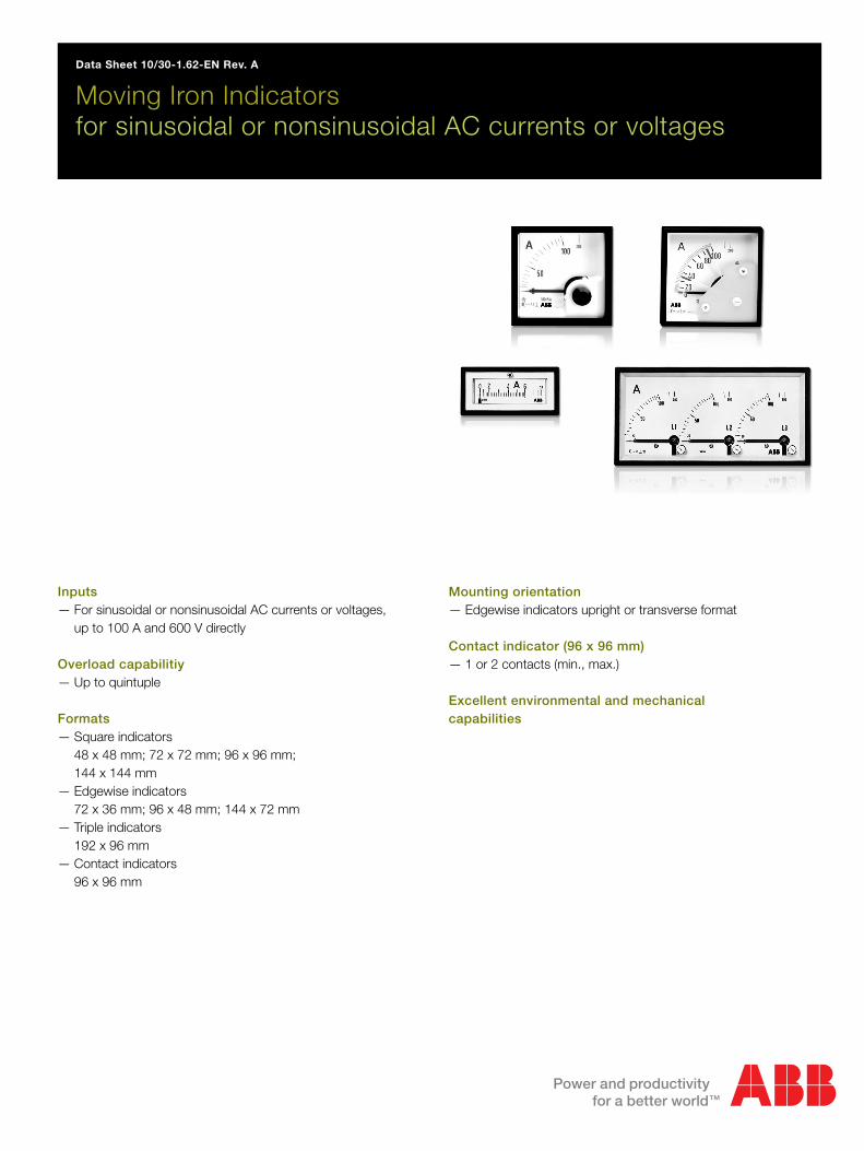
Inputs— For sinusoidal or nonsinusoidal AC
up to 100 A and 600 V directly
Overload capabilitiy— Up to quintuple
Formats— Square indicators
48 x 48 mm; 72 x 72 mm; 96 x 96 144 x 144 mm
— Edgewise indicators72 x 36 mm; 96 x 48 mm; 144 x 72
— Triple indicators192 x 96 mm
— Contact indicators96 x 96 mm
atorsnonsinusoidal AC currents or voltages
currents or voltages,
mm;
mm
Mounting orientation— Edgewise indicators upright or transverse format
Contact indicator (96 x 96 mm)— 1 or 2 contacts (min., max.)
Excellent environmental and mechanical capabilities

Moving Iron Indicators 10/30-1.62 ENFor Sinusoidal or Non-Sinusoidal AC Currents/Voltages
General data
StandardsThe indicators comply with DIN EN 60051 and with the safetyregulations according to DIN EN 61010-1.
In the sections below you can find a short description of the mostimportant parts of these regulations regarding the constructionand the characteristics of electrical measuring instruments.
Measured errorThe measured error of an indicator or its accessories is given bythe limits through basic errors and effects.
The indicators comply with Class 1.5, if no other measured errorrating has been given for specific types. Optionally, indicatorscan also be supplied for higher class measured errors, if this ispossible. The class involved is always stated on the scale.
Mounting orientationGenerally, the nominal position is indicated by a position symbol.For indicators without such a position identification, the referencerange is any vertical or horizontal position. The nominal mountingorientation is 5° in every direction of the reference position. Notethat the effect (in addition to the indicated error) must not begreater than 50 % of the respective classified error.
Temperature effectIf not otherwise stated, the reference temperature is 23 °C ± 2 Kfor indicators of Class 0.5 to 5. The additional error for a nominalrange of ±10 K within this temperature range must not exceedthe classified error.
General technical specifications
Measured errorClass 1.5 to DIN EN 60051
Measuring rangesThe measuring ranges comply with DIN 43701(standardized progression: 1 - 1.5 - 2.5 - 4 - 6 and their decadic multiples ), see the respective codes in the measuring range tables
Mounting orientationvertical, if not otherwise specified, 2a...2c in the illustration
Connectiondirectly or via transformer
Ambient temperature23 °C ± 2 K
Temperature influence< 1 %/10 K
Front frameto DIN 43700exchangeable front pane (only for square instruments with plastichousings)
Front colorblack, RAL 9005
Environmental conditions to DIN EN 60721-2-1, 2, 5
Mechanical category to DIN EN 60068
Vibration = Part 2-6normal versionfrequency range 5...55 Hzacceleration max. 2.5 gNo. of cycles 5runtime 1 octave per minute
Shock = Part 2-27normal versionacceleration max. 15 gtime of action 11 ms
2
3
4
Z-
38
52
a b c
11:
2:3:
4:
=
=
90
9090
0
ConditionsPermissible variablesNormal measuring instruments→ H, Y, G
Relatively tropicalized instruments→ H, V, F
Operating temperature -25...+40 °C -25...+55 °CRelative humidity max. 85 %, but not
more than 60 days per year, otherwise 75 %,annual average 65%(max. temperature +27 °C)
max. 95 %, but not more than 30 days per year, otherwise 85 %,annual average 75%(max. temperature +25 °C)
Condensation none none
2
Moving Iron Indicators 10/30-1.62 ENFor Sinusoidal or Non-Sinusoidal AC Currents/Voltages
Scale and pointer designThe scales and pointers for square, circular, vertical or horizontal scalescomply with DIN 43802, Parts 2 and 4.
Type of protectionIf not otherwise specified, the indicators comply with DIN EN 60529
IP 52 for caseIP 00 for terminals
Application range
Square indicators15…100 Hz
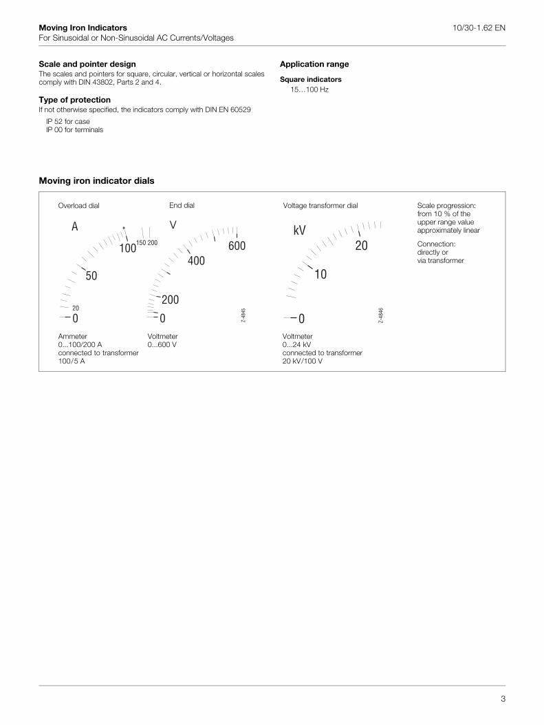
Moving iron indicator dials
Z-48
45
A A
0
50
100
200
0
400600
20
150 200
Overload dial End dial
Ammeter0...100/200 Aconnected to transformer100/5 A
Voltmeter0...600 V
Voltage transformer dial
Voltmeter0...24 kV connected to transformer20 kV/100 V
kV
0
10
20
Z-48
46
Scale progression: from 10 % of the upper range valueapproximately linear
Connection:directly orvia transformer
V
3
Moving Iron Indicators 10/30-1.62 ENFor Sinusoidal or Non-Sinusoidal AC Currents/Voltages
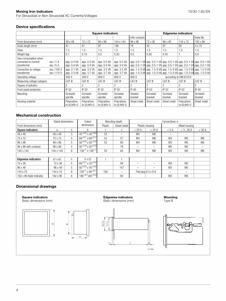
Device specifications
Mechanical construction
Dimensional drawings
Square indicators Edgewise indicatorswith contacts triple No.
Front dimensions (mm) 48 x 48 72 x 72 96 x 96 144 x 144 96 x 96 72 x 36 96 x 48 144 x 72 192 x 96Scale length (mm) 41 61 97 146 78 45 67 92 3 x 72Class 1.5 1.5 1.5 1.5 1.5 1.5 1.5 1.5 1.5Weight (kg) 0.1 0.15 0.2 0.25 0.5 0.28 0.45 1 0.9Own consumption when connected to current transformer
sec./1 Asec./5 A
app. 0.4 VAapp. 0.4 VA
app. 0.5 VAapp. 0.4 VA
app. 0.5 VAapp. 0.4 VA
app. 0.5 VAapp. 0.4 VA
app. 0.5-1 VAapp. 0.5-1 VA
app. 0.5-1 VAapp. 0.5-1 VA
app. 0.5-1 VAapp. 0.5-1 VA
app. 0.5-1 VAapp. 0.5-1 VA
app. 0.5-1 VAapp. 0.5-1 VA
Connection to voltage transformer
sec./100 Vsec./110 V
app. 2.1 VAapp. 2.3 VA
app. 3.5 VAapp. 3.7 VA
app. 3.5 VAapp. 3.7 VA
app. 3.5 VAapp. 3.7 VA
app. 1.5-3 VAapp. 1.5-3 VA
app. 1.5-3 VAapp. 1.5-3 VA
app. 1.5-3 VAapp. 1.5-3 VA
app. 1.5-3 VAapp. 1.5-3 VA
app. 1.5-3 VAapp. 1.5-3 VA
Operating voltage 300 V 300 V 600 V 600 V 600 V according to DIN 61010Measuring voltage category CAT III CAT III CAT III CAT III CAT III CAT III CAT III CAT III CAT IIIDegree of pollution 2 2 2 2 2 2 2 2 2Front panel protection IP 52 IP 52 IP 52 IP 52 IP 40 IP 52 IP 52 IP 52 IP 40Mounting Screwed
spindleScrewed spindle
Screwed spindle
Screwed spindle
Srewedbracket
Screwedbracket
Screwedbracket
Screwedbracket
Screwedbracket
Housing material Polycarbon.to UL94V-0
Polycarbon. to UL94V-0
Polycarbon.to UL94V-0
Polycarbon.to UL94V-0
Sheet metal Sheet metal Sheet metal Polycarbon. to UL94V-0
Sheet metal
Rated dimensions Cutoutdimensions
Mounting depth Connections: eFront dimensions (mm) Plastic Sheet metal Plastic housing Metal housingSquare indicators a h b c c < 25 A > 25 A < 3 A > 3...30 A > 30 A48 x 48 48 x 48 5 45+0.6 x 45+0.6 53 – M4 M6 – – –72 x 72 72 x 72 5 68+0.7 x 68+0.7 53 57 M4 M6 M3 M5 M696 x 96 96 x 96 5 92+0.8 x 92+0.8 53 60 M4 M6 M3 M5 M696 x 96 with contacts 96 x 96 5 92+0.8 x 92+0.8 78 – – M5 M5 –144 x 144 144 x 144 8 138+1 x 138+1 53 60 M4 M6 M3 M5 M6
Edgewise indicators a1 x a2 h l1 x l2 t t72 x 36 72 x 36 5 68+0.7 x 33+0.6 94 – – M3 M596 x 48 96 x 48 5 92+0.8 x 45+0.6 107 – – M3 M5144 x 72 144 x 72 8 138+1 x 68+0.7 192 – Flat plug 6.3 x 0.8 – –192 x 96 triple indicator 192 x 96 8 186+0.1x92+0.8 60 M3 M5
Square indicatorsBasic dimensions (mm)
Edgewise indicatorsBasic dimensions (mm)
MountingType B
Z-17869
c
ba
4
Moving Iron Indicators 10/30-1.62 ENFor Sinusoidal or Non-Sinusoidal AC Currents/Voltages
Contact indicators (96 x 96 mm)
ApplicationThe contact indicator FO 96 with one or two alarm values isinstalled in a sheet metal case and is suitable for monitoring cur-rents or voltages.
It is equipped with one or two relay outputs with change-overcontacts. The contacts are optionally available as min. or max.contacts, so there are five different versions:
– Min. minimum contact– Max. maximum contact– Min./Max. minimum and maximum contact– Min./Min. minimum and early warning contact– Max./Max. maximum and early warning contact
The standard version relays operate according to the NC operat-ing principle: they open, when an alarm limit is exceeded or fallenbelow or in case of a power failure. Optionally, the devices areavailable with NO contact operation.
Functional principleMoving iron mechanism with M-core system, silicon oil dampingand resilient jewel bearing. Integrated components optically mea-sure the set alarm values via the pointer position and control thepotential-free relay outputs.
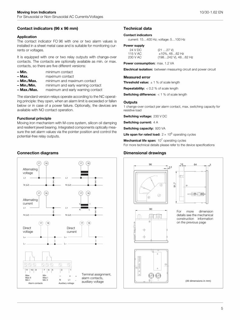
Connection diagrams
Technical data
Contact indicatorscurrent: 15…400 Hz; voltage: 5…100 Hz
Power supply24 V DC (21 …27 V)
115 V AC ±10%, 48…62 Hz230 V AC (198…242 V), 48…62 Hz
Power consumption: max. 1.2 VA
Electrical isolation: between measuring circuit and power circuit
Measured errorThreshold value: ± 1 % of scale length
Repeatability: < 0.2 % of scale length
Switching difference: < 1 % of scale length
Outputs1 change-over contact per alarm contact, max. switching capacity for resistive load
Switching voltage: 230 V DC
Switching current: 4 A
Switching capacity: 920 VA
Life span for rated load: 2 × 10⁶ operating cycles
Mechanical life span: 107 operating cyclesFor more technical details please refer to the device specifications
Dimensional drawings
17 18
L1
N (L2)
17 18
L1
N (L2)
Alternating voltage
17 18
L1
N (L2)
17 18
L1
N (L2)
K L
lk
Alternatingcurrent
17 18
L+
L–
17 18
L+
L–
Directcurrent
Directvoltage
1356791011
90
964,5
6414 5
91,7
For more dimensiondetails see the mechanicalconstruction informationon the previous page
5
Terminal assignment,alarm contacts,auxiliary voltage
MaxMax IIMin I
MinMax IMin II
Auxiliary voltage
+–N L1
=
~Alarm contacts
(All dimensions in mm)

Moving Iron Indicators 10/30-1.62 ENFor Sinusoidal or Non-Sinusoidal AC Currents/Voltages
Ordering information
Moving Iron Indicator Variant digit No. 1 - 8 CodeSquare, 90° scale Catalog No. F48-NW 48 x 48 mm max. 25 A V30078A-F72-NW 72 x 72 mm V30077A-F96-NW 96 x 96 mm V30079A-F144-W 144 x 144 mm V30080A-Measuring RangeVia current transformer x A/1 A (primary current acc. to ZWU code No.) 801Via current transformer x A/5 A (primary current acc. to ZWU code No.) 800Via voltage transformer x V/100 V (primary voltage acc. to ZWU code No.) 703Via voltage transformer x V/110 V (primary voltage acc. to ZWU code No.) 70440 mA...100 A (indicate code No., see measuring range table) 3_ _6 V...600 V (indicate code No., see measuring range table) 7_ _As specified (clear text) ZAMScaleSame as measuring range ZSAWithout graduation, start/end marked, with symbol strip and company logo ZSNAs specified (in clear text, ZEM code No.) ZEMVia transformer connector (indicate code No. ZWU see scale table)Overload RangeWithout overload ZFS1.2-fold overload ZFU2-fold overload (only for current ranges) ZFD5-fold overload (only for current ranges) ZFF
Moving Iron Indicator Variant digit No. 1 - 8 CodeEdgewise Catalog No. F72-PW 72 x 36 mm V30073A-F96-PW 96 x 48 mm V30074A-F144-PW 144 x 72 mm V30082A-F192-3PW 192 x 96 mm (triple indicator) V30076A-Measuring RangeVia current transformer x A/1 A (primary current acc. to ZWU code No.) 801Via current transformer x A/5 A (primary current acc. to ZWU code No.) 800Via voltage transformer x V/100 V (primary voltage acc. to ZWU code No.) 703Via voltage transformer x V/110 V (primary voltage acc. to ZWU code No.) 704100 mA...25 A (indicate code No., see measuring range table) 3_ _6 V...600 V (indicate code No., see measuring range table) 7_ _As specified (in clear text, ZAM code No.) ZAMScaleSame as measuring range ZSAWithout graduation, start/end marked, with symbol strip and company logo ZSNAs specified (in clear text, ZEM code No.) ZEMVia transformer connector (indicate code No. ZWU see scale table)Overload RangeWithout overload ZFS1.2-fold overload ZFU2-fold overload (only for current ranges) ZFDMounting OrientationTransverse format ZFQUpright format ZFHSpecial FeaturesTransformer ratio (code No. according to measuring range table) ZWU
see next page for more special features
6
Moving Iron Indicators 10/30-1.62 ENFor Sinusoidal or Non-Sinusoidal AC Currents/Voltages
Ordering information
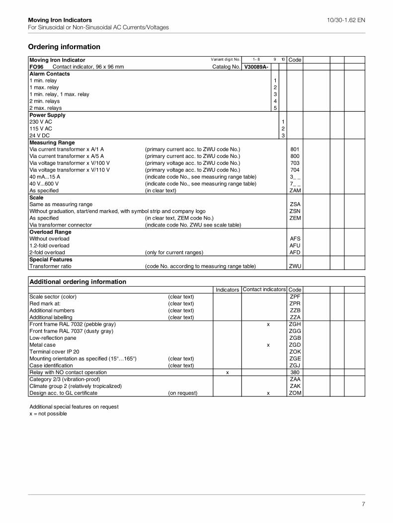
Moving Iron Indicator Variant digit No. 1 - 8 9 10 CodeFO96 Contact indicator, 96 x 96 mm Catalog No. V30089A-Alarm Contacts1 min. relay 11 max. relay 21 min. relay, 1 max. relay 32 min. relays 42 max. relays 5Power Supply230 V AC 1115 V AC 224 V DC 3Measuring RangeVia current transformer x A/1 A (primary current acc. to ZWU code No.) 801Via current transformer x A/5 A (primary current acc. to ZWU code No.) 800Via voltage transformer x V/100 V (primary voltage acc. to ZWU code No.) 703Via voltage transformer x V/110 V (primary voltage acc. to ZWU code No.) 70440 mA...15 A (indicate code No., see measuring range table) 3_ _40 V...600 V (indicate code No., see measuring range table) 7_ _As specified (in clear text) ZAMScaleSame as measuring range ZSAWithout graduation, start/end marked, with symbol strip and company logo ZSNAs specified (in clear text, ZEM code No.) ZEMVia transformer connector (indicate code No. ZWU see scale table)Overload RangeWithout overload AFS1.2-fold overload AFU2-fold overload (only for current ranges) AFDSpecial FeaturesTransformer ratio (code No. according to measuring range table) ZWU
Additional ordering informationIndicators Code
Scale sector (color) (clear text) ZPFRed mark at: (clear text) ZPRAdditional numbers (clear text) ZZBAdditional labelling (clear text) ZZAFront frame RAL 7032 (pebble gray) x ZGHFront frame RAL 7037 (dusty gray) ZGGLow-reflection pane ZGBMetal case x ZGDTerminal cover IP 20 ZOKMounting orientation as specified (15°…165°) (clear text) ZGECase identification (clear text) ZGJRelay with NO contact operation x 380Category 2/3 (vibration-proof) ZAAClimate group 2 (relatively tropicalized) ZAKDesign acc. to GL certificate (on request) x ZOM
Additional special features on requestx = not possible
Contact indicators
7

Moving Iron Indicators 10/30-1.62 ENFor Sinusoidal or Non-Sinusoidal AC Currents/Voltages
Measuring range table Transformer/scale table
Grad. Code No. Graduation Code No.48 x 48 72 x 72 Contact 72 x 36 A A
96 x 96 indicators 96 x 48 10 314144 x 144 144 x 72 15 324
192 x 96 20 334mA mA 25 34440 361 x 30 35460 381 x 40 364
100 312 50 374150 322 60 384250 342 75 358400 362 100 315600 382 150 325A A 200 3351 313 250 345
1.5 323 300 3552.5 343 400 3654 363 500 3755 373 600 3856 383 750 36810 314 800 39515 324 kA kA25 344 x 1 31640 364 x x x 1.2 31860 384 x x x 1.5 326V V 2 3366 780 2.5 34610 711 3 35615 721 kV kV25 741 0.5 27240 761 0.6 28260 781 1 213
100 712 3 253150 722 5 273250 742 6 283400 762 10 214
Format Format
10/3
0-1.
62 E
N R
ev. A
ABB has Sales & Customer Supportexpertise in over 100 countries worldwide.
The Company’s policy is one of continuous productimprovement and the right is reserved to modify the
information contained herein without notice.
Printed in the Fed. Rep. of Germany (12.2006)
© ABB 2006
ABB Ltd.Howard Road, St. NeotsCambridgeshire, PE19 8EUUKTel.: +44 (0)1480 475321Fax: +44 (0)1480 217948
ABB Inc.125 E. County Line RoadWarminster, PA 18974USATel.: +1 215 674 6000Fax: +1 215 674 7183
ABB Automation Products GmbHBorsigstr. 263755 AlzenauGermanyTel: +49 551 905-534Fax: +49 551 [email protected]
500 772 20 234600 782 25 244
30 254x = not possible or only on request


10/3
0-1.
62-E
N R
ev. A
01.
2011
Contact us
NoteWe reserve the right to make technical changes or modify the contents of this document without prior notice. With regard to purchase orders, the agreed particulars shall prevail. ABB does not accept any responsibility whatsoever for potential errors or possible lack of information in this document.
We reserve all rights in this document and in the subject matter and illustrations contained therein. Any reproduction, disclosure to third parties or utilization of its contents – in whole or in parts – is forbidden without prior written consent of ABB.
Copyright© 2011 ABBAll rights reserved
3KXJ100001R1001
ABB Ltd.Process AutomationHoward Road, St. NeotsCambridgeshire, PE19 8EUUKPhone: +44 (0)1480 475321Fax: +44 (0)1480 217948
ABB Inc.Process Automation125 E. County Line RoadWarminster PA 18974USAPhone: +1 215 674 6000Fax: +1 215 674 7183
ABB Automation Products GmbHProcess AutomationBorsigstr. 263755 AlzenauGermanyPhone: +49 551 905-534Fax: +49 551 905-555
www.abb.com