cwl12d clarke woodlathe manual - clarke … brown coloured cord to plug terminal marked letter...
TRANSCRIPT

OPERATING & MAINTENANCE
INSTRUCTIONS
37” WOODLATHEModel No. CWL12D
Part No. 6500680
12/97

Lathe Specifications ................................................................................................... 3
General Safety Instructions ........................................................................................ 5
Wood Lathe Safety Instructions ................................................................................. 6
Electrical Connections and Motor Specifications................................................... 7
Unpacking And Checking Contents ........................................................................ 8
Assembly And Installation .......................................................................................... 9
Understanding your Lathe ....................................................................................... 11
Spindle Speeds and Belt Tensioning ....................................................................... 12
Preparation for use (Spindle/Faceplate/Outboard Turning & Indexing) ........... 13
Using Woodworking Chisels and Basic Techniques ............................................... 18
Making Standard Cuts ............................................................................................. 23
Spindle Turnings ......................................................................................................... 26
Miscellaneous Operations ....................................................................................... 28
Face Plate And Chuck Turnings .............................................................................. 29
Fancy Face Plate Turnings ....................................................................................... 30
Turning Plastics .......................................................................................................... 33
Sanding, Buffing And Polishing ................................................................................ 34
Maintenance ............................................................................................................ 35
Lubrication ................................................................................................................. 35
Optional Accessories ............................................................................................... 36
Spares And Servicing ................................................................................................ 36
Parts List ...................................................................................................................... 37
Parts Diagram ............................................................................................................ 38
CONTENTS PAGE
2

GUARANTEE
This CLARKE product is guaranteed against faulty manufacture for a period of 12 months from thedate of purchase. Please keep your receipt as it will be required as proof of purchase. This guaranteeis invalid if the product is found to have been abused or tampered with in any way, or not used for thepurpose for which it was intended.
Faulty goods should be returned to their place of purchase, no product can be returned to us without
Thank you for purchasing this CLARKE 37” Wood lathe, designed for DIY and semi professional use.
Before assembling this machine, please read this manual thoroughly and follow all instructionscarefully. In doing so you will ensure the safety of yourself and that of others around you, and you can
3
WARNING:THIS MACHINE MUST NOT BE MODIFIED, OR USED FOR ANY PURPOSE
SPECIFICATIONS
Motor .............................................................................................. 230V 50Hz 1Ph
Power Rating ................................ 370W
Switch Type ................................... No Volt Release
Turning Capacity (Between Centres) ....................... 37 in (940mm)
(Over Bed) .................................... 12 in Dia (305mm)
Spindle Speeds 1. .................................................... 475 RPM
2. .................................................... 838 RPM
3. .................................................... 1374 RPM
4. .................................................... 2215 RPM
5. .................................................... 3260 RPM
Headstock Drive Spindle Inboard .......................................... a. No. 1 Morse Taper
....................................................... b. External 3/4 UNF thread
Outboard ...................................... External 3/4 UNF Left Handthread
Tailstock Spindle ............................................................................ No. 1 Morse Taper
Tailstock Spindle Advance ........................................................... 2 3/8 in (60mm)via hand wheel)
Overall Dimensions (LxWxH) ......................................................... 541/8 x 153/4 x 121/8 in(1,375x400x308 mm)

1. KNOW YOUR MACHINE.Read the manual carefully. Learn themachines applications and limitations, aswell as the specific potential hazardspeculiar to it.
2. KEEP GUARDS IN PLACEand in working order.
3. EARTH ALL MACHINES.If the machine is equipped with three-pinplug, it should be plugged into a three-pinelectrical socket. Never remove the earthpin.
4. REMOVE ADJUSTING KEYS AND WRENCHES.
5. KEEP WORK AREA CLEAN.Cluttered areas and benches inviteaccidents.
6. DON’T USE IN DANGEROUS ENVIRONMENT.Don’t use machinery in damp or wetlocations, or expose them to rain. Keepwork area well lit.
7. KEEP CHILDREN AND VISITORS AWAY.All children and visitors should be kept asafe distance from work area.
8. MAKE WORKSHOP CHILDPROOFUse padlocks, master switches or removestarter keys etc.
9. DON’T FORCE THE MACHINE.It will do the job better and safer, at the ratefor which it was designed.
10. USE RIGHT TOOL.Don’t force a tool or attachment to do ajob for which it was not designed.
11. WEAR PROPER APPAREL.Loose clothing, gloves, neckties, rings,bracelets, or other jewellery may getcaught in moving parts. Nonslip footwear isrecommended. Long hair should be
contained.
12. USE SAFETY GLASSES.Also use face or dust mask if cuttingoperation is dusty. Everyday eyeglassesonly have impact resistant lenses, they areNOT safety glasses.
13. USE EAR DEFENDERS.
14. DON’T OVERREACH.Keep proper footing and balance at alltimes.
15. MAINTAIN TOOLS IN TOP CONDITION.Keep tools sharp and clean for best andsafest performance. Follow instructions forlubricating and changing accessories.
16. ALWAYS DISCONNECT THE MACHINEbefore servicing or changing accessories.
17. AVOID ACCIDENTAL STARTING.Ensure the machine is switched OFF beforeplugging in.
18. CHECK FOR DAMAGE.If part of the machine (eg. A cover orguard), is damaged, it should be carefullyinspected to ensure that it can perform its’intended function correctly. If in doubt, thepart should be renewed. Damage tomoving parts or major components shouldbe Inspected by a qualified technicianbefore operating the machine. Contactyour local dealer for advice.
19. DO NOT STAND ON THE MACHINE.Serious injury could occur if the machine istipped over. Do not store materials aboveor near the machine such that it isnecessary to stand on the machine to getto them.
20. NEVER operate a machine when under the
GENERAL SAFETY RULES FOR OPERATING MACHINERY
WARNINGAs with all machinery, there are certain hazards involved with their operation and use. Exercisingrespect and caution will considerably lessen the risk of personal injury. However, if normal safety
4

1. IMPORTANT: You should not operate thismachine unless you are thoroughly familiarwith wood turning lathes and wood turningtechniques. If there is any doubt whatsoever,you should consult a qualified person.
2. Do not operate the machine until it iscompletely assembled, and this entiremanual, has been read and understood.
3. Ensure the proper electrical regulations arefollowed. The machine must be properlyearthed.
4. Before switching the machine ON, ALWAYS:-a. Clear the lathe bed of ALL objects
(tools, scraps of wood etc.).b. Examine the setup carefully, ensuring
nothing could possibly interfere withthe rotating workpiece. eg. The toolrest is secure and not liable to swinginto the workpiece. Rotate workpieceby hand to check.
c. Ensure the tool rest is adjusted to thecorrect height, and is as close to theworkpiece as possible.
d. Ensure all clamps are properly secured.e. Ensure your clothing is properly adjusted.f. Ensure the workpiece is centralised.
5. Make all adjustments with the powerOFF.
6. ALWAYS use the slowest speed whenstarting a new workpiece, and cut atcorrect speed for material and shape.
7. ALWAYS remove the tool rest when sandingor polishing.
8. When turning between centres, alwaysensure that the tailstock centre is snugagainst the workpiece, with the spindlelocked, AND the Tailstock securely lockedto the bed. NEVER loosen the tailstockspindle OR the tailstock with the workpieceturning.NOTE: The centre should be lubricated(unless it is a ball bearing type).
9. DO NOT drive the workpiece into thecentre when the centre is installed in theheadstock. Always set the workpiece intothe centre with a soft mallet first, and then
mount the Centre with workpiece attachedinto headstock spindle.
10. When using the Faceplate, ensure theworkpiece is securely fastened to it andthe appropriate size faceplate is used tocorrectly support the workpiece. Ensure thesecuring screws cannot interfere with theturning tool at the finished dimension.
11. ALWAYS rough cut the workpiece as closeas possible to the finished shape beforemounting on to a faceplate.
12. ALWAYS examine the workpiece for flaws.Do not use wood which is split or has knots.Test glued joints before mounting on tolathe to ensure they have completely set.
13. When roughing off, DO NOT jam tool intoworkpiece or take too big a cut.
14. NEVER attempt to remount a faceplateturning to the faceplate for any reason.Never attempt to remount a between-centres turning if the original centres in theturning have been altered or removed.
15. ALWAYS clean the machine at the end of aworking session. Remove centres from theheadstock AND tailstock and store them.Ensure the work area is cleaned beforeleaving the machine.
16. Should any part of the lathe be missing,damaged, or fail in any way, or anyelectrical component fail to performproperly, shut OFF the machine anddisconnect from the power supply. Replacemissing, damaged or failed parts beforeresuming operation. If in doubt, consultyour local dealer. Always disconnect frompower supply when carrying our repairs.
17. Be particularly careful with your clothingwhen operating a lathe. Always wearsafety glasses. Long hair should becontained. See General Safety Instructions- Apparel.
18. Do not exceed recommended speeds.Refer to chart on page 12
ADDITIONAL SAFETY RULES FOR WOOD LATHES
5

ELECTRICAL CONNECTIONS
Connect the mains lead to a standard 230 volt (50Hz) electrical supply using a 13 amp BS1363 plugfitted with a 13 amp fuse. or a suitably fused isolator switch.
WARNING : THIS APPLIANCE MUST BE EARTHED.
IMPORTANT : The wires in the mains lead are coloured in accordance with the following code :
Green & Yellow - Earth
Blue - Neutral
Brown - Live
As the colours of the flexible cord of this appliance may not correspond with the coloured markingsidentifying terminals in your plug, proceed as follows :-
Connect GREEN & YELLOW coloured cord to plug terminal marked with a letter “E” or Earthsymbol ‘ ’ or coloured GREEN or GREEN & YELLOW.
Connect BROWN coloured cord to plug terminal marked letter “L” or coloured RED.
Connect BLUE coloured cord to plug terminal marked letter “N” or coloured BLACK.
We recommend that this unit is fitted with a Residual Current Device (RCD)
FUSE RATINGThe fuse for the plug in this appliance must be rated at 13 amps.
MOTOR SPECIFICATIONS
The five speed pulley system of this lathe is designed to use a 1725 RPM, 370W motor. Rotation isclockwise as viewed from the pulley end of the shaft. It is wired for 230 Volt, 50Hz.
Caution: Do not any other type of motor as their use may be hazardous.
6
The machines’ ON and OFF buttons are marked “I” for ON and “O” for OFF.
Should the power fail whilst the machine is in use, the NO VOLT RELAY will operate. This is a safetyfeature which prevents the machine from starting up automatically when the power is restored. It

Your wood lathe is shipped complete in one carton.
Separate all parts from packing materials and check against the lists below to ensure that all itemsare accounted for, before discarding any packing material.
If any parts are missing or damaged in any way, please contact your Clarke dealer immediately.
A. Head stock assembly.
Includes : Drive spindle, motor, drive belt,pulleys (2), pulley guard, spindle nut, ON-OFF switch , power cable, and outboardspindle cover.
B. Bed. (1- Headstock End, 2 - Foot End)
C. Foot
D. Bed Clamping bolt
UNPACKING AND CHECKING CONTENTS OF CARTON
Fig. 1
E. Tailstock assembly
F. Tool rest bracket
G. Tool rest base
H. Tool rest -12"
J. Tool rest - 6"
K. Faceplate - 4"
TABLE OF LOOSE PARTS
Fig. 2 L. Locking handle assemblies (4 pcs)
M. Tool rest locking handle
N. Mounting bolts c/w nuts and washers (4pcs)
O. Tool rest bracket securing bolt
P. Brass slugs (2 pcs)
Q. Screw (countersunk head)
R. Flat washer
S. 31/2” Bolt c/w nut and washers
T. 1/2” Pan head wood screws (3 pcs)
U. Spur Centre
V. Revolving Centre
W. Hex. wrenches (2 pcs)
Also included but not shown - one bagcontaining loose parts and tools,listed below.
7

2. ASSEMBLY OF LATHE BED HALVES.
2.1 Assemble the two bed halves (steel tubes)together by inserting the Headstock end(the tube with the plugged end carrying thethreaded hole in the centre of the plug),into the machined inside diameter of theTailstock end .
2.2 Insert the ‘V’ shaped portion of the foot (C),into the open, exposed Tailstock end andthen insert the bed clamping bolt (D) ,through the foot and into the threaded holein the plugged headstock end. Start thethread but do not tighten at this time.
NOTE: It may assist by turning the completebed assembly on its end to locate the longbolt into the threaded hole in the end ofthe headstock bed end.
2.3 Align the two keys (the strips of metalattached to each bed half with screws) sothat they line up exactly. This alignment isnecessary so that the Tail Stock Assembly(E), and the Tool Rest Base (G), will slide freelyover the joint formed by the two halves ofthe bed.
To carry out this alignment, first align the twokeys by eye as close as possible. Next, usinga metal straight edge against one side ofthe keys, slide the end of the straight edgeacross the joint first from one side of the jointand then from the opposite side. If there isa “click” or a hang-up of the straight edgeat the joint, it will be obvious what relativedirection the two halves of the bed will haveto be rotated to achieve alignment.Repeat this process as many times asnecessary, on both sides of the key, to besatisfied tha alignment has been attained.
When satisfied, screw in the singlecountersunk headed screw (Q), through thehole in the key and into the tailstock end sothat the two halves of the bed are nowsecured.
2.4 Nip up the Bed clamping bolt (but do notfully tighten), so that when the foot is placedon the bench, the key is facing downwards.
3. ASSEMBLY OF BED TO HEADSTOCK
3.1 Slide the tail stock assembly (E), and the toolrest base assembly (G), on to the bed asshown in Fig. 10.
Ensure the Clarke label on the Tailstock andthe threaded hole in the tool rest base(shown in fig 4), faces towards the front.
3.2 Now insert the bed assembly into theheadstock assembly (A), fully, andmanoeuvre the lathe so that the bed isparallel to the front edge of the bench.
4. SECURING THE LATHE TO THE BENCH
4.1 Mark the position of the two Foot mountingholes and drill two 10mm holes in the bench.
4.2 Insert the Foot mounting bolts, and shakethe complete assembly to ensure it is stableand lying flat on the bench. When satisfied,nip up all four mountings - finger tight only.
REMEMBER At this stage the bed clampingbolt must not be tight.
ASSEMBLY AND INSTALLATION Ref. Figs. 1 & 2
1. MOUNTING HEADSTOCK TO BENCH
1.1 Drill two 10mm holes in your bench or standaccording to diagram, Fig. 3.
Note: Make sure the top of your bench ispositioned so that your don’t drill into the legs orrail underneath.
1.2 Position the headstock assembly (A) on thebench and insert two 5/16" x 2" carriagebolts through the two mounting holes in thebase. Place a flat washer, a lock washerand a nut from the underside on each bolt.Tighten nuts - only finger tight at this time.
Fig.3
Fig.4
8
If the bed is too loose however, the weightof the Tailstock and Tool rest base maycause the bed to rotate. In this event, nip`up the Bed Securing Set Screw (T, fig 10).
4.3 For additional rigidity of the motor and it’smounting brackets, a 8mm hole must bedrilled through the bench top using the holein the hinge bracket (V, fig 10), as a pilot. Itwill be necessary to remove the fourmounting bolts and moving the headstockslightly to facilitate the drilling of the hole.
Locate 1/4" x 3 1/2” long hex. head bolt inthe bag of loose parts together with 2 plainflat washers, a spring lock washer and a nut.Place a plain flat washer on to the bolt andinsert the bolt through the hinge brackethole and on through the bench top. Fromthe underside of the bench, place a plainflat washer, the spring lock washer and thenthe nut, on to the bolt. Do not tighten fully.
4.4 Next, secure the belt guard to the benchwith wood screws. Open the blade guardcover to reveal three holes in the bottomflange of the plate. Locate three 1/2 inchlong pan head wood screws in the bag ofloose parts. Ensure the plate is parallel to thebelt and the cover opens and closes easilythen screw in the wood screws loosely.
4.5 Gently shake the complete assembly toensure it is stable and lying flat on the bench,and when satisfied, tighten the fourmounting bolts followed by the motorbracket securing bolt and the three woodscrews, fully.
5. COMPLETING THE ASSEMBLY
The 4 locking handles are used to lock theTailstock and the Tool Rest base to the bed, theTool Rest to its bracket, and to lock the Tailstockspindle to prevent it from moving duringoperation.
Before screwing the handles in place, ensurethat a brass slug is inserted in each of the holeswhere the Tailstock and the Tool Rest base aresecured to the bed. i.e. the threaded holeshown in the tool rest base in Fig. 4, and thetailstock locking handle hole. (see fig. 6).
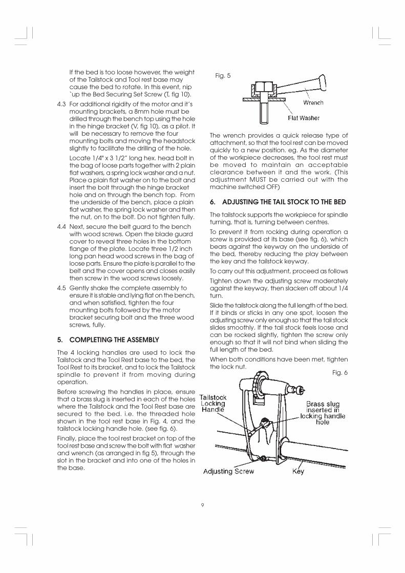
Finally, place the tool rest bracket on top of thetool rest base and screw the bolt with flat washerand wrench (as arranged in fig 5), through theslot in the bracket and into one of the holes inthe base.
9
Fig. 5
The wrench provides a quick release type ofattachment, so that the tool rest can be movedquickly to a new position. eg. As the diameterof the workpiece decreases, the tool rest mustbe moved to maintain an acceptableclearance between it and the work. (Thisadjustment MUST be carried out with themachine switched OFF)
6. ADJUSTING THE TAIL STOCK TO THE BED
The tailstock supports the workpiece for spindleturning, that is, turning between centres.
To prevent it from rocking during operation ascrew is provided at its base (see fig. 6), whichbears against the keyway on the underside ofthe bed, thereby reducing the play betweenthe key and the tailstock keyway.
To carry out this adjustment, proceed as follows
Tighten down the adjusting screw moderatelyagainst the keyway, then slacken off about 1/4turn.
Slide the tailstock along the full length of the bed.If it binds or sticks in any one spot, loosen theadjusting screw only enough so that the tail stockslides smoothly. If the tail stock feels loose andcan be rocked slightly, tighten the screw onlyenough so that it will not bind when sliding thefull length of the bed.
When both conditions have been met, tightenthe lock nut.
Fig. 6

Slide the tailstock toward the headstock sothat the two points of the centres are veryclose but not touching. Tighten the tailstocklock.
Loosen the bed clamping bolt (D), in thefoot, about two turns.
Using a 3/16 hex wrench (supplied), loosenthe bed securing set screw, located on theback of the head stock (T, fig. 10).
Swing the tailstock so that the points of theCentres coincide perfectly, then tighten thebed securing set screw and the bedclamping bolt (D), firmly.
5. ALIGNING THE CENTRES
5.1 The spur centre and the revolving centreare used for spindle turning and shouldalways be in alignment. To align centresrefer to Fig. 7 and adjust as follows:
5.2 Insert spur centre into head stock spindleand revolving centre into tailstock spindle.
Note: Do not drive or hammer centres intotheir spindle’s as it is completelyunnecessary, and removal may be difficult.Simply tap them home with a piece ofwood.
10
Fig. 7
Fig. 8
6. REMOVAL OF SPUR CENTRE FROMSPINDLE
To remove the spur centre from spindle, hold thespindle pulley with one hand whilst turning thespindle nut on the threaded portion of thespindle, with a spanner, anticlockwise until thecentre is ejected.
7. REMOVAL OF REVOLVING CENTRE
To remove revolving centre from tail stockspindle, insert a 6mm dia. rod through the holein the tailstock spindle. Hold the centre with onehand and tap the rod with a hammer.
Fig. 9

LATHE PARTS, CONTROLS, NOMENCLATURE AND FUNCTIONS
Become familiar with the nomenclature and purpose of the various operating controls and parts ofyour lathe. Please read and fully understand this manual before attempting to perform any operation.
J. HEX. NUT. Used for the removal of the SpurCentre.
K. SPUR CENTRE.
L. TOOL REST BRACKET LOCK. Clamps the toolrest bracket to the tool rest base.
M. TOOL REST LOCK. Clamps the tool rest to thetool rest bracket.
N. TOOL REST BASE LOCK. Clamps the baseand hence the complete tool rest assemblyto the bed.
O. TAILSTOCK SPINDLE LOCK. Locks the spindlein position during operation.
P. TAILSTOCK LOCK. Clamps the tailstock to thebed.
Q. HAND WHEEL. Adjusts the tailstock spindle.
R. ROTATING CENTRE.
S. INDEX PIN. Engages with the spindle pulleyto produce equal spacing for variousoperations such as fluting, reeding or fordividing face plate work. DO NOT use toremove the Centre.
This pin MUST be DISENGAGED for normaloperations.
T. BED LOCKING SCREW. Hex socket headscrew.
U. MOTOR BRACKET MOUNTING HOLE.
V. DRIVE BELT ADJUSTER.
UNDERSTANDING YOUR LATHE
A. HEADSTOCK
B. BED
C. TAILSTOCK
D. TOOL REST
E. ON BUTTON (I)
F. OFF BUTTON (O)
G. BELT GUARD LOCK. Ensures the cover islocked during operation
H. WARNING LABEL. Essential instructions whichshould be complied with.
I. OUTBOARD SPINDLE END COVER. Protectsthe operator from rotating outboard end ofthe spindle when not being used foroutboard turning.
11
Fig. 10

SPINDLE SPEEDS
A chart showing spindle speeds and recommended turning speeds is mounted on the pulley cover,and for convenience, is duplicated as follows:
If you wish to run at a slower speed, say 1374RPM, you must shift the belt inwards, 1 step.
CAUTION : MAKE SURE THE POWER CORD ISREMOVED FROM THE OUTLET BEFOREATTEMPTING TO CHANGE THE BELT POSITION.
BELT TENSION ADJUSTMENT
Belt tension is provided by the weight of themotor pivoting the motor mounting bracketdownward through the “hinge” of the hingebracket. To increase the belt tension, screw inthe adjustment bolt located in the corner of themotor mounting bracket (V, fig. 10), thusrestricting downward pivoting travel.Conversely, loosening the adjusting bolt allowsincreased pivot on the bracket thus decreasingbelt tension.
12
SPINDLE SPEEDS
Fig. 11
RECOMMENDED GENERAL SPEEDS
SPINDLE TURNING
SQUARE LENGTH ROUGHING FINISHING
1” (25mm) 12” (305mm) 1374 3260
2” (50mm) 18” (455mm) 838 2215
3” (75mm) 24” (610mm) 838 2215
4” (100mm) 30” (760mm) 475 2215
5” (125mm) 36” (915mm) 475 2215
DIAMETER THICKNESS ROUGHING FINISHING
12” (305mm) 4” (100mm)Max. 475 1374
10” (255mm) 4” (100mm)Max. 838 2215
8” (205mm) 4” (100mm)Max. 1374 2215
6” (150mm) 4” (100mm)Max. 2215 3260
FACE PLATE TURNING
Fig.11 shows the belt positioned on the secondstep from the outside edge of the pulley. Thisproduces a spindle speed of 2215 RPM. (Referto the chart above).

PREPARATION
1. SPINDLE TURNING
If you are not experienced at the art of woodturning, we suggest that you practice using thevarious wood turning tools, starting with turninga small spindle.
1.1 Select a piece of wood 50x50x305mm.
NOTE:
If you use a ‘dead centre’ i.e not a rotatingtype, put a drop of oil or wax on the woodwhere it contacts the centre. This willlubricate the wood whilst it is turning.
1.8 Place the wood between the centres andlock the tailstock.
1.9 Move the rotating centre into the wood byturning the tailstock hand wheel. Ensure thecentres are “seated” into the wood, into theholes made in steps 5 and 6 above.
Rotate the wood by hand whilst turning the
13
1.2 Draw diagonal lines on each end to locatethe centres.
1.3 On one end, make a saw cut approximately2mm deep on each diagonal line. This isfor the spur centre.
1.4 The other end is the rotating centre. Placethe point of the centre on the wood wherethe diagonal lines cross.
1.5 Drive the centre into the wood. Use awooden mallet or a plastic hammer, but puta piece of wood on the end of the centreto protect it.
1.6 Remove the rotating centre and drive thespur centre into the other end of the wood.Make sure the spurs are in the saw cuts.Remove the spur centre.
1.7 Make sure the centres and the hole in thespindle and the tailstock spindle are clean.Insert the spur centre into the headstockand the rotating centre into the tailstockand tap them in lightly with a piece of wood.DO NOT DRIVE THEM IN.
Wooden Malletor
tailstock hand wheel.
5.10 Adjust the tool rest so that it is approximately1/8" away from the corners of the wood and1/8" above the centre line.
Lock the tool rest base and the tool rest.
5.11 Consult the speed chart. Note that a 50mmsquare turning, up to 455mm long, shouldrun at 838 RPM for “roughing”. Check andadjust the drive belt if necessary.
IMPORTANT. ALWAYS rotate the wood by handto guarantee that the corners do not strike thetool rest, and that the indexing pin is notengaged.
Fig. 12
Fig. 14
Fig. 13
Fig. 15

5.12 Check to ensure there are no spanners/wrenches/pieces of wood or other debrisin the area, and that your clothing isproperly adjusted before pushing the ONbutton.
The procedure for cutting and the use ofwoodworking chisels is described under “UsingWoodworking Chisels, starting on page 15. Seealso ‘Spindle Turning’ on page 24.
3. INDEXING
14
2. FACEPLATE TURNING
Turning which cannot be worked throughcentres, must be mounted on a faceplate, orother work-holding device. (Some jobs mayrequire the use of special chucks).
All face plate work is done by scraping. Anyattempt to use a cutting technique on edgegrain, will result in hogging or gouging, whichmay tear the tool out of your hands.
For Faceplate turning, the work (suitably trimmedso that it is as near to its final dimension aspossible), should be firmly mounted on to thefaceplate, using screws as appropriate (see fig16).The complete assembly is then screwed on tothe headstock spindle, and tightened securely,by holding the faceplate, and turning thespindle nut using a 27mm or 1-1/16 AF spanner,to lock it up against the faceplate boss.
Fig. 17
The screws used in securing the work to the faceplate, must not be of sufficient length as tointerfere with the tool at the final dimension. Itmay be necessary to screw the work to abacking piece, depending upon design, orwhere screws are not permissible at all, the workmay be glued to a backing piece, fitting a pieceof paper at the joint, which will allow for laterseparation without damaging the wood.
Fig. 16
The spindle pulley contains 36 equally spacedholes. The index pin engages with these holesto keep the spindle from turning whilst you put amark on the workpiece.
For example, to locate the position of six spokesin a wheel :
2.1 Pull the index pin outward and turn it so thatthe small cross pin slips into the slot. This willallow the index pin to engage in one of theholes in the pulley and prevent the spindlefrom turning.
2.2 Adjust the tool rest approximately at thecentre line of the workpiece and make amark.
Fig. 18

2.3 Pull out the index pin and slowly rotate theworkpiece until the pin slides into the nexthole in the pulley.
2.4 Do this six times and put the next mark onthe workpiece. The two marks will bespaced 60° apart. Continue this operationuntil six spokes are marked 60° apart.
2.5 Spindle turning can be divided in the samemanner.
WARNING: The indexing pin must be disengagedfor all other operations on the lathe.
Fig. 19
15
3. OUTBOARD TURNING
This technique is used to do jobs that are toolarge to mount conventionally. It is straightforward faceplate turning except that becauseof the work size, extra caution must be takenand speeds must be restricted to minimums.
In order to perform outboard turning operations,you must first build a stand similar to the oneshown in Fig. 19. This is no more than a tool restsupport.
Ensure that the top-to-floor distance allows youplace the chisel on the work centre line.
DO NOT PUSH THIS SUPPORT WHEN CUTTING.
DO NOT TRY TO MOUNT WORK SO LARGE THATTHE MOTOR MUST STRAIN TO TURN IT.
IF YOU WISH TO EXPERIMENT WITH THISTECHNIQUE DO SO WITH SOFT WOODS - LET THEHEAVIER, HARDER WOOD COME LATER.
The outboard end of the spindle is under thepulley cover and is protected by a plastic cap.This end is provided with a left hand threadwhich will accept available face plateaccessories .
Remove the protective cap, and screw on theface plate with workpiece attached. (See faceplate turning on page 26).

Better chisels have handles approximately 10"(250mm) long, to provide plenty of grip andleverage. Sharp tools are essential for clean,easy work. Buy tools that will take and hold keenedges.
An 8 piece chisel set is available from yourCLARKE dealer, part no. 6500649
2. THEORY OF TURNING
There are two classes of chisel; these are :
a. Chisels intended primarily for cutting, and
b. Chisels used only for scraping.
The cutting chisels are the gouge, skew andparting tool. These are most commonly used.They are sharpened to a razor edge by honingon both sides.The scraping chisels are the flat nose, round noseand spear point. These are not honed on theflat sides, the wire edges produced by grindingare left on to aid in the scraping process.
Cutting is faster than scraping and produces asmoother finish which requires less sanding.However, it is far more difficult to master.Scraping, on the other hand, is far more preciseand easier to control.
2.2 When You Can Cut and When You MustScrape.
18
USING WOODWORKING CHISELS
THE SIX MOST COMMONLY USED CHISEL TYPES
2.1 Cutting and ScrapingTo cut, the chisel is held so that the sharp edgeactually digs into the revolving work to peel offa shaving.
To scrape, the chisel is held at a right angle tothe work surface as shown in fig. 22, andremoves fine particles instead of shavings.
Many operations require that the cutting chiselsbe used for scraping, but scraping chisels arenever used for cutting. Scraping dulls a chiselmust faster, especially the razor sharp cuttingchisels.
Cutting Chisel Scraping Chisel
There are two different types of cut to considerwhen turning.
One is cutting at the circumference of theworkpiece (for example, turning down the outersurface of a cylinder or the inner wall of a hollowround box, as shown in fig. 23). In this approachthe surface being turned travels under the chiseledge like an endless belt.
The second type is cutting at the diameter of aworkpiece (as when turning the face offaceplate turning or the side of a large shoulderon a spindle turning, as shown in fig. 23). In thisapproach the surface being turned rotates likea disc under the chisel edge. Sometimes theapproach will be a combination of both.
Fig. 20
Fig. 22
Fig. 21
Fig. 23
1. SELECTION OF CHISELS

Either a cutting or scraping action can be usedwhen cutting at the circumference. The shavingis removed like a peeling from a potato.
Scraping only, is used when cutting at thediameter. The reason is obvious when youconsider that faceplate turning always requiresremoval of wood across the grain. Wood doesnot peel easily across the grain, and attemptsto use a cutting method will result in damage tothe work and throwing of the chisel by the work.
It follows that a cutting action is used for themajority of spindle turning operations, whilst themajority faceplate turning is done by thescraping method.
When a combination approach is to be used,you will have to judge, by the feel of the work,when to stop cutting and start scraping.
Never try to cut when it becomes difficult to holdthe chisel against the roughness of the woodgrain.
2.3 How To Position The Tool Rest forCircumference Cutting
When cutting, the object is to pierce the outerskin of wood to a certain desired depth, then tohold the chisel steady, with the bevel edgeparallel to the work circumference, so that it willpeel off a shaving at this desired depth.
The only sure method of holding the chiselsteady is to rest the bevel against the work, asshown in sketch 1. When the tool rest is atthe proper height , thechisel can be held withthe bevel pressedagainst the work, andthe tool rest will act as afulcrum to support thechisel against thedownward force of therevolving work.
If the rest is placed toolow, so that the chisel isheld with the bevel outfrom the work (Sketch2), the cutting edge willcontinue to dig deeperinto the work. It will digin until the “bite”becomes so deep thatyour hands have
19
difficulty holding thechisel, then theimproperly supportedchisel will begin tobounce, or chatter,against the workpiece.
If the rest is placed toolow, the chisel must beheld extremely high toposition the bevelagainst the work(Sketch 3). Then the restloses most of its value asa fulcrum, and thedownward force of therevolving workpiecetends to kick the chiselback out of your hands.
If the rest is placed toohigh, (Sketch 4) and thechisel is correctlypositioned for cutting, itstrikes the workpiecenear the top where thedirection of forceexerted by theworkpiece is nearlyhorizontal, andkickback will againresult.
If the rest is placed toofar out from the worksurface (Sketch 5) then,when correctly held, thechisel is again too highon the work. Also, youhave less leverage onyour side of the tool rest,and it is even moredifficult to hold thechisel.
With large diameterwork (Sketch 6), the toolrest can be above theworkpiece centre line,and somewhat out fromthe work surface.
With small diameterwork (Sketch 7), the restshould not be far fromthe work surface. Aswork grows smaller, therest should be

2.4 How to Position Tool Rest forCircumference Scraping
In scraping operations, the tool rest position isnot as critical as it is for cutting operations. Thechisel generally is held horizontally, though it canbe held at an angle to reach into tight places.Considering that the wire edge of the chiseldoes the scraping, sketches 9 and 10 show theresults of too low or too high a position for therest, and sketch 8 shows the chisel action withthe rest correctly positioned.
20
2.5 How to Position Chisel and Rest forDiameter Scraping
When scraping on the diameter, that portion of
surface to the right of centre is moving upwards(Sketch 11). If the chisel is placed in this area, itwill simply be carried up off the rest and out ofyour hands. All diameter scraping operationsmust be done at the left of centre.
Three different chisel contact points are shownin Sketch 12. It will be noted that, when the chiselis above the workpiece centre, or below it, thework surface sweeps past the chisels’ edge atan angle and tends to carry the chisel in onedirection or the other along the rest. Only whenthe chisel contacts the work on the centre linedoes the work surface pass squarely under thechisels edge. This then, is the position in which itis easiest to hold the chisel steady. To obtainthis position, place the rest approximately 1/8"(3mm) - thickness of chisel, below the centre.
3. USING THE GOUGE
Three gouges the 1/4”, 1/2”, and 3/4” are amplefor general DIY turning, but other sizes from 1/8”to 2” can be purchased.
The main use of the gouge is for roughcircumference cutting of raw stock down to acylinder of working size. it is the best tool to usefor rapidly cutting away large areas of theworkpiece, but when so used does not producea smooth surface. With practice, it can be usedfor cutting coves and the shaping of long cuts.It is also useful for scraping.
When used for cutting, the gouge is always heldwith the convex side down. It should be rolledapproximately 30° to 45° in the direction in whichit is being advanced along the rest, and thecutting edge will be a little in advance of thehandle.
4. USING THE SKEW
Two skews, the 1/2 and 3/4” sizes, are all thatare needed for general use. Other sizes are
available. This tool is nearly always used to makefinished cuts, to cut vees and beads, and tosquare shoulders. Properly used, it produces thebest finish that can be obtained with a chisel. itshould not be used for scraping, as this quicklydulls it.
For finish cutting, the skew is held with the cutting
Fig. 27
Fig. 25
Fig. 26
Fig. 24

bevel side down, keep the base of the bevelagainst the work. Good practice is to place theskew well over the work, pull it back until theedge begins to cut, then swing the handle intoposition to advance the cut. Both the toe andthe heel of the skew can be used for takinglight cuts, but do not penetrate the wood toodeeply without cutting clearances, as there isdanger of burning the tip of the tool.
5. USING THE PARTING TOOL
The parting tool has just one primary purpose tocut straight into the workpiece as deep as
The spear point is used for fine scraping anddelicate operations, such as the forming ofbeads, parallel grooves and shallow vees. Edgesand bowl contours can be rounded with theround nose chisel. Any flat surface can bescraped with the flat nose chisel.
7. USING SHAPER OR MOULDING KNIVES
desired, or all the way through to make a cut-off, it is therefore a very narrow tool. 1/8 inchwide and shaped to cut its own clearance sothat the edge will not be burned. When usedfor scraping, however, it should be backed offregularly to prevent overheating.
Unlike the gouge and skew, the parting tool isseldom held with the bevel against the work.As the amount of stock removed is small, asupport for the bevel is not necessary. The toolis simply fed into the work at an angle (forcutting), or pointed at the workpiece centre (forscraping) it can be held easily in one hand.
6. USING THE SCRAPING CHISELS
A 1/2” wide spear point chisel, a 1/2” wide roundnose chisel and a 1” wide flat nose chiselcomplete the list of tools ordinarily used by homecraftsmen. Each of these scraping chisels canbe purchased in various other sizes for specialpurposes. All are very useful for diameterscraping operations and for circumferencescraping, when cutting methods cannot beemployed.
An old chisel can be made to serve as a holderfor ‘shaper’ or ‘moulding’ knives. Such knivesmake it possible to scrape many interestingshapes in the workpiece surface in one or twooperations instead of the many operationsrequired with standard chisels. It is generally notpractical to use cutting methods with specialshape tools, scraping methods should be used.
The holder should provide a shoulder againstwhich the butt end of the knife can be firmlyseated, and the knife must be securelymounted, either by means of a screw threadedinto the holder, or be compressing it betweentwo prongs bolted together.
8. USING A BLOCK PLANE
Clear glass smooth finishes (especially on softwoods) can be obtained by using a block planeset to take a fine shaving. The tool rest shouldbe raised up approximately to the top of theworkpiece, and the plane should be horizontal,but turned slightly in the direction of travel sothat it will take a shearing cut. Two tool rests,one in front and the other behind the work, canbe used to advantage in positioning the planeso as to exactly limit the depth of cut (andfinished size of the workpiece).
21
Fig. 29
Fig. 31
Fig. 30
Fig. 28

9. USING WOOD RASPS AND FILES 10.2 Finish Cutting
A wood rasp will remove stock quickly when heldagainst the revolving workpiece. Care shouldbe taken to support the rasp firmly against thetool rest however, as it can tear the handspainfully if caught by a rough edge of theworkpiece and kicked back. The rasp will leavea very rough finish.
Finer finishes (similar to those produced byscraping), can be obtained by using files in thesame manner. Various shape files can be usedfor shaping vees, beads, coves etc. If pressedinto the wood too hard, however, a file can burnthe workpiece surface. Keep the file clean tokeep it cutting uniformly. Files work best on hardwoods.
10. HAND POSITIONS
When handling a chisel, the hand takes anatural position, being nearer or farther from theend depending upon the amount of leveragerequired. The position of the tool rest hand is amatter of individual liking, but there are threegenerally accepted positions, each best forcertain types of operations.
10.1 Roughing Off
Roughing off and other heavy work requires afirm grip and solid positioning of the chiselagainst the rest. This is best obtained by the toolrest hand position as illustrated. The wrist isdropped down so that the heel of the handbelow the little finger acts as a sliding guideagainst the rest. The handle hand controls chiselposition.
Finish cutting requires more control with less forceand is better done with the palm of the tool resthand turned up. The wrist is still held down, andthe side of the index finger acts as a guide alongthe rest. In this position, control of the chisel isshared by both hands, the fingers of the tool resthand being free to assist in positioning the tool.
10.3 Intricate Cutting
Intricate, delicate cutting requires extremecontrol, with practically no force. This is bestaccomplished by guiding the chisel with thefingers of the tool rest hand. The hand is heldpalm up, with the wrist high, and the little fingerplaced against the rest to steady the hand. Thechisel does not touch the rest and the handlehand is completely secondary to the tool resthand.The first and second positions are equally goodfor scraping operations, but the third position isnever used for scraping.
11. CUTTING TO DEPTH
Many scraping operations and cutting to depthwith the parting tool can be easily done withone hand. The chisel is grasped firmly with theindex finger on top, to press it down against therest, and is thrust straight into the work. Holdingthe tool thus leaves the other hand free to holda pattern , callipers etc., to check work progress.
22
Fig. 33
Fig. 35
Fig. 32Fig. 34
Fig. 36

MAKING STANDARD CUTS
1. THE ROUGHING OFF-CUT
Reducing a square or odd shaped workpiecedown to a cylinder of approximate size for finishturning is called roughing-off. Faceplateturnings and large diameter spindles should firstbe partly reduced by sawing , but small spindlesare easily turned down entirely with the large(3/4”) gouge.
Start the first cut about 50mm from tailstock and
then run it toward the tailstock and off the endof the workpiece.
Next, start another cut 50mm nearer theheadstock and run it also toward tailstock tomerge with first cut.
Continue in this manner until 50mm to 100mmfrom the headstock end, then reverse thedirection of tool travel and work one or two cutsin succession toward the headstock and off thisend of the workpiece.
Never start a cut directly at the end. If the chiselcatches the end, it will damage the workpiece.
Never take long cuts while corners remain onthe work, as this tends to tear long slivers fromthe corners.
The first series of cuts should not be too deep. It
is better to partially reduce the work to a cylinderalong its complete length, then start a secondseries of cuts to reduce it to a cylinder. Once acylinder has been formed, step the lathe up toits next fastest speed. Further reductions in sizecan now be carried out by cutting as deeplyas desired at any spot along the work.
At this stage long cuts from the centre of either
23
end can also be taken. Roughing-off generallyis continued until the cylinder is approximately3mm larger than the desired finished size.Roundness can be tested by laying the gougeon top of the work - it will not ride up and downwhen cylinder is perfectly round.
2. ROUGH-CUTTING TO SIZE
The roughing-off cut can be made to accurately
Fig. 37
Fig. 37
Fig. 37
size the cylinder to a given diameter.
Another method is to make a number of sizingcuts at intervals along the work, then use thegouge to reduce the whole cylinder down tothe diameter indicated by these cuts.
3. MAKING SIZING CUTS
Sizing cuts are useful to establish approximatefinish-size diameters at various points along aworkpiece. The work can then be turned downto the diameters indicated and be ready forfinishing.
Diameters for sizing cuts should be planned tobe about 3mm greater than the desired finisheddiameters.A sizing cut is made with the parting tool.Hold the tool in one hand and use the otherhand to hold an outside calliper, preset to thedesired sizing-cut diameter.As the cut nears completion, lower the chiselpoint more and more into a scraping position.When the callipers slip over the workpiece atthe cut, the cut is finished.
4. SMOOTHING A CYLINDER
The final 3mm can be removed in two ways.Either use the 3/4” skew, working from the centretoward both ends and taking lighter and lightercuts until finished.

Use the gouge to remove any waste stockoutside of shoulder, and smooth this section upto within 3mm of the shoulder in the usualmanner. Finishing of the shoulder unless it is morethan 25mm high is best done with the 1/2” skew.First, the toe of the skew is used to removeshavings from the side of the shoulder, down tofinish size. Hold the skew so the bottom edge ofthe bevel, next to shoulder, will be very nearlyparallel to side of shoulder, but with the cuttingedge turned away at the top, so that only theextreme toe will do the cutting.If the cutting edge is flat against the shoulder,the chisel will run. Start with the handle low, andraise handle to advance toe into the work.Cut down to finished diameter of outside area,then clean out the corner by advancing the
heel of the skew into it along the surface of theoutside area.Tilt the cutting edge with handle raised up, sothat only the extreme heel does this cutting. Ifthe shoulder is at the end of work, the process iscalled squaring the end. In this case, reduceouter portion to a diameter about 6mm largerthan tool centre diameter, then later saw off thewaste stock.
6. CUTTING VEES
Vee grooves can be cut with either the toe orheel of the skew. When the toe is used, thecutting action is exactly the same as in trimminga shoulder, except that the skew is tilted to cutat the required bevel. Light cuts should be takenfirst on one side then the other, graduallyenlarging the vee to the required depth andwidth.
When the heel is used, the skew is rotated downinto the work, using the rest as a pivot.Otherwise, the cutting position and sequenceof cuts is the same.
As when using the toe, it is important that cuttingbe done only by extreme end of cutting edge.
If deep vees are planned, it is quicker to startthem by making a sizing cut at the centre ofeach vee. Vees can also be scraped with thespear point chisel or a three-sided file.
7. CUTTING BEADS
This requires considerable practice.
First, make pencil line to locate the tops (highestpoints) of two or more adjoining beads. Thenmake a vee groove at the exact centrebetween two lines, and down to the desireddepth of the separation between the beads.
Be careful not to make the groove too wide oryou will remove portions of the desired beads.
The sides of the two adjoining beads are nowcut with the heel of the skew, preferably 1/2”size, unless beads are quite large. Place theskew at right angles to the work axis, flat againstthe surface and well up near the top. Theextreme heel should be just inside the pencil linethat marks the top of the bead.
24
5. CUTTING A SHOULDER
A shoulder can be the side of a square portionleft in the workpiece, the side of a turned sectionor the end of the workpiece. Most shoulders areperpendicular to the work axis, but a shouldercan be at any angle desired.
First, mark position of the shoulder with a pencilheld to the revolving workpiece. Then make asizing cut with the parting tool, placing this cutabout 2mm outside the shoulder position andcutting to within about 3mm of the depthdesired for the area outside of the shoulder.
If shoulder is shallow, the toe of the skew can beused to make the sizing cut, but do not go indeeper that 3mm with the skew unless wider andwider vees are cut to provide clearance for thistool. Fig. 41
Fig. 42
Fig. 40

MAKING STANDARD CUTS
1. THE ROUGHING OFF-CUT
Reducing a square or odd shaped workpiecedown to a cylinder of approximate size for finishturning is called roughing-off. Faceplateturnings and large diameter spindles should firstbe partly reduced by sawing , but small spindlesare easily turned down entirely with the large(3/4”) gouge.
Start the first cut about 50mm from tailstock andthen run it toward the tailstock and off the endof the workpiece.
Next, start another cut 50mm nearer theheadstock and run it also toward tailstock tomerge with first cut.
Continue in this manner until 50mm to 100mmfrom the headstock end, then reverse thedirection of tool travel and work one or two cutsin succession toward the headstock and off thisend of the workpiece.
Never start a cut directly at the end. If the chiselcatches the end, it will damage the workpiece.
Never take long cuts while corners remain onthe work, as this tends to tear long slivers fromthe corners.
The first series of cuts should not be too deep. Itis better to partially reduce the work to a cylinderalong its complete length, then start a secondseries of cuts to reduce it to a cylinder. Once acylinder has been formed, step the lathe up toits next fastest speed. Further reductions in sizecan now be carried out by cutting as deeplyas desired at any spot along the work.
23
At this stage long cuts from the centre of eitherend can also be taken. Roughing-off generallyis continued until the cylinder is approximately3mm larger than the desired finished size.Roundness can be tested by laying the gougeon top of the work - it will not ride up and downwhen cylinder is perfectly round.
2. ROUGH-CUTTING TO SIZE
Fig. 37
Fig. 37
Fig. 37
The roughing-off cut can be made to accuratelysize the cylinder to a given diameter.
Another method is to make a number of sizingcuts at intervals along the work, then use thegouge to reduce the whole cylinder down tothe diameter indicated by these cuts.
3. MAKING SIZING CUTS
Sizing cuts are useful to establish approximatefinish-size diameters at various points along aworkpiece. The work can then be turned downto the diameters indicated and be ready forfinishing.
Diameters for sizing cuts should be planned tobe about 3mm greater than the desired finisheddiameters.A sizing cut is made with the parting tool.Hold the tool in one hand and use the otherhand to hold an outside calliper, preset to thedesired sizing-cut diameter.As the cut nears completion, lower the chiselpoint more and more into a scraping position.When the callipers slip over the workpiece atthe cut, the cut is finished.
4. SMOOTHING A CYLINDER
The final 3mm can be removed in two ways.Either use the 3/4” skew, working from the centretoward both ends and taking lighter and lightercuts until finished.

Use the gouge to remove any waste stockoutside of shoulder, and smooth this section upto within 3mm of the shoulder in the usualmanner. Finishing of the shoulder unless it is morethan 25mm high is best done with the 1/2” skew.First, the toe of the skew is used to removeshavings from the side of the shoulder, down tofinish size. Hold the skew so the bottom edge ofthe bevel, next to shoulder, will be very nearlyparallel to side of shoulder, but with the cuttingedge turned away at the top, so that only theextreme toe will do the cutting.If the cutting edge is flat against the shoulder,the chisel will run. Start with the handle low, andraise handle to advance toe into the work.Cut down to finished diameter of outside area,then clean out the corner by advancing the
heel of the skew into it along the surface of theoutside area.Tilt the cutting edge with handle raised up, sothat only the extreme heel does this cutting. Ifthe shoulder is at the end of work, the process iscalled squaring the end. In this case, reduceouter portion to a diameter about 6mm largerthan tool centre diameter, then later saw off thewaste stock.
6. CUTTING VEES
Vee grooves can be cut with either the toe orheel of the skew. When the toe is used, thecutting action is exactly the same as in trimminga shoulder, except that the skew is tilted to cutat the required bevel. Light cuts should be takenfirst on one side then the other, graduallyenlarging the vee to the required depth andwidth.
When the heel is used, the skew is rotated downinto the work, using the rest as a pivot.Otherwise, the cutting position and sequenceof cuts is the same.
As when using the toe, it is important that cuttingbe done only by extreme end of cutting edge.
If deep vees are planned, it is quicker to startthem by making a sizing cut at the centre ofeach vee. Vees can also be scraped with thespear point chisel or a three-sided file.
7. CUTTING BEADS
This requires considerable practice.
First, make pencil line to locate the tops (highestpoints) of two or more adjoining beads. Thenmake a vee groove at the exact centrebetween two lines, and down to the desireddepth of the separation between the beads.
Be careful not to make the groove too wide oryou will remove portions of the desired beads.
The sides of the two adjoining beads are nowcut with the heel of the skew, preferably 1/2”size, unless beads are quite large. Place theskew at right angles to the work axis, flat againstthe surface and well up near the top. Theextreme heel should be just inside the pencil linethat marks the top of the bead.
24
5. CUTTING A SHOULDER
A shoulder can be the side of a square portionleft in the workpiece, the side of a turned sectionor the end of the workpiece. Most shoulders areperpendicular to the work axis, but a shouldercan be at any angle desired.
First, mark position of the shoulder with a pencilheld to the revolving workpiece. Then make asizing cut with the parting tool, placing this cutabout 2mm outside the shoulder position andcutting to within about 3mm of the depthdesired for the area outside of the shoulder.
If shoulder is shallow, the toe of the skew can beused to make the sizing cut, but do not go indeeper that 3mm with the skew unless wider andwider vees are cut to provide clearance for thistool. Fig. 41
Fig. 42
Fig. 40

Now draw the skew straight back whilst raisingthe handle slowly, until the edge of the heel atthe pencil line starts to cut.
As the edge begins to cut, roll the skew in thedirection of the vee, so that the exact portionof the edge, when started cutting, will travel ina 90° arc down to the bottom of the vee.
Upon reaching the bottom of the vee, the skewshould be on edge. Reverse the movements tocut the side of the adjacent bead.
It is important that only the extreme heel shoulddo the cutting. This means that the bottom edgeof the bevel, next to the vee, must at all timesbe tangent to the arc of the bead being formed.
Easier beads can be shaped with a spear pointchisel. Use pencil marks and sizing cuts asbefore. Push the chisel straight into each cutand rotate it horizontally to round off theadjacent edges. It must be moved slightly inthe direction of rotation at the same time, tokeep the point from digging into the adjacentbead.
8. CUTTING COVES (CONCLAVES)
This is the most difficult single cut to master, butone of the most important in good wood turning.First, use pencil marks to indicate the edges.Then rough-it out to within about 3mm of thedesired finish surface by scraping with the gougeor round nose chisel. If the cove is to be verywide, sizing cuts can be made to plot theroughing out.Once it is roughed out, the cove can be finishedin two cuts, one from each side to the bottomcentre.At the start of either cut, the gouge is held withhandle high and the two sides of blade heldbetween the thumb and forefinger of tool resthand, just behind the bevel.Position the fingers ready to roll the blade intocove. Hold the blade so that bevel is at a 90°angle to the work axis, with the point touchingthe pencil line and pointing into work axis.
From here, depress the tip slightly to start the cut,then continue to move tip down in an arctoward the bottom centre cove, at the sametime rolling chisel uniformly so that at the end ofthe cut it will be flat at the bottom of the cove.The object is to keep the extreme tip of thegouge doing the cutting from start to finish.Reverse movements to cut the opposite side.
Coves can be scraped to finish using the roundnose chisel or a file, but these methods do notgenerally produce perfectly curved coves.
9. MAKING A LONG CONVEX CUTS
First turn work down to approximate size, usingsizing cuts (as required) to determine variousdiameters. Finish cut can then be made witheither skew or gouge.If the skew is used, the principles of operationare the same as those employed in cutting abead, except that the curve is longer and maybe irregular. Use the extreme heel throughout.Start at the longer end of the curve (if curve isirregular) and progress toward the steeper end.If a gouge is used, make the cut in the samedirection. Start with the handle well back fromthe point, swinging it in the direction of tool travelto overtake the point, if necessary, when thesteep part of the curve is reached. The object isto keep the extreme point doing the cuttingthroughout, with the bevel at a tangent to thecurve as much as possible.
10. MAKING LONG TAPER CUTS
Long taper cuts are made like long convex cuts,with the skew or gouge. However, the anglebetween the cutting edge and handle is keptconstant during the entire cut. The handle isnot swung around. Always cut downhill. Do notcut too deeply at the centre of the taper.
25
Fig. 46
Fig. 45
Fig. 44
Fig. 43

SPINDLE TURNINGS
1. PLOTTING THE SHAPE
Once the basic cuts have been mastered, youare ready to turn out finished work.
The first step is to prepare a plan for the proposedturning. This can be laid out on a suitable sheetof paper, and should be to full size.
Next, prepare the turning stock by squaring itup to the size of the largest square or roundsection in your plan. The stock can be cut tothe exact length of the proposed turning, but inmost cases it is best to leave the stock a littlelong at one or both ends to allow for trimming.
2. DUPLICATE TURNINGS
Identical turnings require great accuracy whenplotting the work and doing the various cuts.Many methods have been devised to assist inperfecting the work.
2.1 Use of PatternsProfessional workers generally use a pattern orlayout board.This is a thin piece of wood or cardboard onwhich is drawn a full-size half section of theturning. The contour of the finished surface isdrawn first, then the diameters at various criticalpoints are drawn to scale as vertical linesintersect the contour line.By placing the pattern against the roughed-out-cylinder, you can quickly mark the various pointsof the critical diameters.To make each sizing cut, use outside callipersand set these by actually measuring the lengthof the vertical line on the pattern whichrepresents the diameter desired. Then make thesizing cut, down to the proper diameter by usingthe callipers to determine when the cut isfinished.After making the sizing cuts, hang the patternbehind the lathe where it will serve as a guidefor completion of the workpiece.
Mount the stock in the lathe, and rough it off toa maximum size cylinder. Now project your planon to the turning by marking the various criticaldimensions along the length of the spindle inpencil. These dimensions can be laid out withan ordinary ruler, or by using a template. Makethe pencil marks about 12mm long, they will bevisible when the work is revolved under power,and can be quickly traced around the spindleby touching each line with the pencil.
After marking, use the parting tool to make sizingcuts at all of the important shoulders. Whenlearning, you will find it best to make sizing cutsto accurately plot the various diameters, butexperienced workers can do with a few suchcuts at the important shoulders.
Plan each sizing cut so that it is in waste stock,and make each deep enough so that there willbe just enough wood left under the cut for thefinishing process.
Once the sizing cuts have been run in, rough-out the excess wood with a gouge, thenproceed with the finishing process by makingthe various types of cuts required.
26
Fig. 47
2.2 Using a Template and a Diameter BoardWhen many identical turnings are to beproduced, it is convenient to have a preparedtemplate. This can be made of thin wood orcardboard, and is cut on a band saw or scrollsaw to have the exact contour of the finished
Fig. 48

3. LONG SPINDLES
A long turning can be worked in short sections,with joints arranged to be at shoulders wherethey will not be noticed.
Long thin work that is likely to whip while turningshould be supported at one or two places by abackstick. This is easy to make. A simple oneconsists of a short length of wood mountedvertically in an extra tool rest, and notched sothat it can be used to support the spindle frombehind. An improved type which uses 2 rollerskate wheels to form the notch-size is shown.
27
turning. The first finished turning can also be usedas a template.Attach the template to a board, then mountthe board behind the lathe on hinges, so thatthe template can be moved down to touch theworkpiece and allow you to closely observeprogress of your work.If a great many turnings are being produced, adiameter board will save the time used forresetting callipers. This is simply a thin boardalong the edge of which a number ofsemicircular cuts have been prepared torepresent all the various calliper settings requiredfor measuring the sizing cuts. Each semicircularcut is held against the workpiece instead of usingthe callipers.
Position the backstick against a pre-turnedportion near the centre of the spindle, thisportion being at least 3mm over finish size toallow for later removal of any marks made uponit.
Operate lathe at a slower speed than normal.Lubricate the workpiece at point of contact withthe backstick, using beeswax (preferably), orgrease.
After completing the turning, remove thebackstick and finish off the original point ofcontact. Sand off any slight burns remaining onworkpiece.
4. CUTTING DOWELS
Dowels of any size can be turned quickly withthe simple jig shown. If the stock is prepared asa split or quartered turning, half round andquarter rounds will be produced.
The jig uses a 1/2” gouge as the cutting tool andwill produce dowels up to 11mm diameter. Makethe jig from suitable hardwood stock as shown.
The hole through the jig must be large enoughat the side, to the left of the gouge, to allowpassage of the square stock. At the right of thegouge this hole must be just the diameter of thefinished dowel. Make the jig so you can holdand guide it by hand.
To start, centre the stock as you would for aspindle turning and turn down about 50mm atthe right end to desired size.Then remove the stock, place your jig over theturned end, with turned portion through thesmaller jig hole, and re-centre the stock on thelathe.Hold the jig firmly and start the lathe. Push thejig slowly right to left along the stock until thewhole dowel is complete.
Fig. 50
fig. 51
Fig. 49

MISCELLANEOUS OPERATIONS
1. GUIDE BLOCKS FOR SCRAPINGOPERATIONS
A guide block can be clamped to a chisel tolimit the depth of cut and aid the productionof perfect cylinders, tapers and facings onfaceplate turnings. Scraping methods must beused when the guide block is employed.
it in the headstock, using a 4-jaw (metal-lathe)chuck or a Jacobs chuck.When this method is employed, there is noaccurate support for the workpiece so thatcentre drilling is difficult. However, cross drilling,or drilling random holes through stock can beaccomplished quickly in this manner.
For cross drilling flat sided work, use a (metal-lathe) drill pad in the tailstock and place a scrapboard between the pad and the work.
For cross drilling round stock, use a (metal-lathe)crotch centre in the tailstock. Work may besupported on supporting blocks laid upon thelathe bed, it can be held by hand or can besupported from behind by a drill pad mountedin the tailstock.
2. DRILLINGThere are several methods of using the lathefor drilling centre holes through wood stock.
When the drill is properly mounted, centeringof the hole is automatic. One method is tomount the drill to the tailstock, while the work isheld and revolved by the headstock. If the drillhas a Morse taper shank, it can be mounteddirectly in some tailstock spindles. Otherwise, itcan be mounted in a chuck fitted with theproper type shank.
Another method of holding the drill is to mount
28
Fig. 53
Fig. 52
Fig. 54

FACEPLATE & CHUCK TURNINGS
1. PLANNING THE WORK
wood bit available. This can be accomplishedas illustrated above, or in any of the ways shownon pages 18 & 19. Be careful to measure inadvance the depth to which the drill can beallowed to go.
Now remove the bulk of the waste (to rough-out the desired recess), by scraping with theround-nose chisel or the gouge. Remove up towithin 1/8” of finished size in this manner.
Make a layout first, to provide a visual patternto follow while working the turning. Patterns canbe laid out in the same manner as spindlepatterns, or templates can be made which canbe held against the work for visual comparison.Circles to locate the various critical points (atwhich the contours of the faceplate take distinctform) can be quickly scribed on the rotatingwork by using dividers (see above).
2 PLANNING VARIOUS CUTS
The circumference of a faceplate turning isroughed-out and finished in the same manneras that for a spindle. Practically all of thebalance of the operations however, are doneby using scraping methods.
A few of the standard contours which are oftenturned are illustrated in fig.56, which also showsthe proper chisels for shaping these contours.Any roughing out to depth that must be done isgenerally accomplished with the gouge held inthe scraping position.
3. DEEP RECESSES
The first step is to remove as much wood aspossible by boring into the centre with the largest
Finish off the inside circumference by scrapingwith the spear point chisel or skew. Smooth thebottom of the recess by scraping it flat with theflat nose chisel.
Proper support must be provided at all times forthe scraping chisels. Several tool rest positionsare shown in the accompanying illustrations.Always endeavour to position the part of the restthat supports the tool as close to the workingsurface as possible.
The depth and squareness of the sides of therecess can be quickly checked by holding oneof the straight sided chisels and a combinationsquare as shown.
29
Fig. 56
Fig. 57Fig. 55
Fig. 58

FANCY FACEPLATE TURNINGS
After making a recess at least 1/2 the waythrough the workpiece, and finishing this on theinside, remove the workpiece from the lathe.Now mount a short length of soft wood stock onthe screw centre and turn this down to form adowel that will be a tight press (not driving) fitinside the recessed end of the cylinder. Mountthe cylinder on this wooden chuck, and recessthe unworked end deep enough to form aperfect hole through the entire cylinder.
3. RECHUCKING
Rechucking is the general term used to describeany additional work mounting that is necessaryto complete a turning project. The method ofworking cylinders, and the use of a plug chuckas already described are typical examples.Another good example is the rechucking of abowl.
1. PREPARING A PLUG CHECK
A plug check is an auxiliary wood chuckmounted onto a faceplate. The chuck can beany size diameter, should be about 65mm thickfor stability and should be provided with a 20mmhold in the centre for receiving a tenon turnedat the end of the workpiece. Once made, suchchucks are permanent useful fixtures for turningballs, goblets etc. In use, the wood stock forturning is turned between centres to produce atenon at one end which will be a driving fit inthe hole of the chuck. When mounted in thechuck, the workpiece is substantially supportedfor any faceplate type of turning.
2. TURNING CYLINDERS
Stock for cylinders should be mounted on thescrew centre or a small faceplate. The tailstockcan be brought up to support the work whilethe circumference is being turned and finished.Afterwards, the tailstock is backed off and theouter end of the cylinder is recessed, usingmethods already described for making deeppresses.
The work is mounted on a wood backing blocksecured to the large faceplate, and is turned inthe usual manner, except for the back side(which is against the mounting block). It is thenremoved from the mounting block. An auxiliarychuck of soft wood is now made in the samemanner as that for the cylinder chuck. Thischuck must have a turned recess properly sizedto accommodate the rim of the bowl in a tightpress fit. When the bowl is mounted in this chuck,the bottom can be cleaned off and slightlyrecessed to complete the desired contours.
4. TURNING A RING
One method of turning a ring requires a spindlechuck. The work stock is first mounted to abacking block held by the large faceplate, andis turned to shape on the outer side. The insidediameter of the ring is also shaped, all the waythrough to the backing block. The work is thenremoved from the backing block. A spindlechuck is now prepared so that it will be a tightpress fit inside the ring, and the ring is reversed
30
Fig. 62
Fig. 61
Fig. 60
Fig. 59

and mounted on this chuck. thus mounted, theremaining contours can be turned to shape.
After being chucked the remaining face of thering can be turned to the proper contour, thuscutting away the centre portion.
Work of this type take constant measurements,or better still, use a template to guard againstover or under cutting.
5. TURNING BALLS
Another method of turning a ring makes use ofa recessed chuck. The work stock is mountedon a screw centre and one half of the ring isformed, but the ring is not cut away from itscentre. The stock is then removed and arecessed chuck, mounted on the largefaceplate, is prepared to receive the ring in atight press fit.
Wooden balls of large size are first roughly turnedbetween centres, using standard procedures.Smaller balls can be mounted as face plates onthe small faceplate of screw centre. Lines drawnto indicate the centre and ends of the ballshape are helpful in plotting the curve. Atemplate should always be used for accuratevisual observation of the work progress.
If the ball is mounted as a faceplate turning,almost the entire surface can be turned beforeit becomes necessary to rechuck it. Rechuckingcan be accomplished in a deep cut chuck,which will hold the finished portion of the ball ina tight press fit. Another method of rechuckingis to use a shallow cup chuck which will notsupport the ball alone, but must be used inconjunction with the tailstock. When using theshallow chuck, a wood block is fitted to thetailstock so that the ball can revolve upon it. Thisblock should be lubricated with beeswax orgrease. In using the shallow chuck method, the
31
Fig. 66
Fig. 65
Fig.64
Fig. 63
ball is constantly shifted, never more than 1/8turn and always with a definite pattern. Sinceturning between centres makes the work aperfect sphere across the grain, the ball mustbe mounted in the chuck so that the firstscraping cuts will round it up in the oppositedirection .
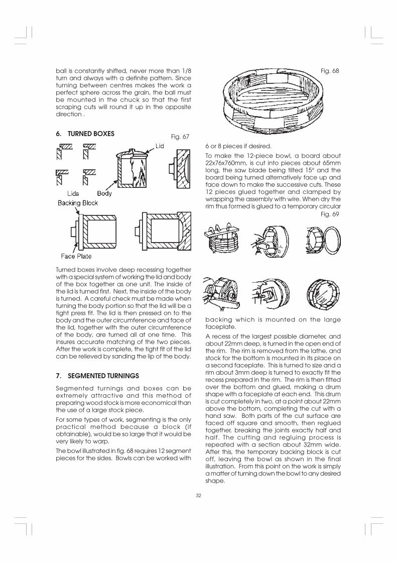
6. TURNED BOXES
6 or 8 pieces if desired.
To make the 12-piece bowl, a board about22x76x760mm, is cut into pieces about 65mmlong, the saw blade being tilted 15° and theboard being turned alternatively face up andface down to make the successive cuts. These12 pieces glued together and clamped bywrapping the assembly with wire. When dry therim thus formed is glued to a temporary circular
Turned boxes involve deep recessing togetherwith a special system of working the lid and bodyof the box together as one unit. The inside ofthe lid is turned first. Next, the inside of the bodyis turned. A careful check must be made whenturning the body portion so that the lid will be atight press fit. The lid is then pressed on to thebody and the outer circumference and face ofthe lid, together with the outer circumferenceof the body, are turned all at one time. Thisinsures accurate matching of the two pieces.After the work is complete, the tight fit of the lidcan be relieved by sanding the lip of the body.
7. SEGMENTED TURNINGS
Segmented turnings and boxes can beextremely attractive and this method ofpreparing wood stock is more economical thanthe use of a large stock piece.
For some types of work, segmenting is the onlypractical method because a block (ifobtainable), would be so large that it would bevery likely to warp.
The bowl illustrated in fig. 68 requires 12 segmentpieces for the sides. Bowls can be worked with
backing which is mounted on the largefaceplate.
A recess of the largest possible diameter, andabout 22mm deep, is turned in the open end ofthe rim. The rim is removed from the lathe, andstock for the bottom is mounted in its place ona second faceplate. This is turned to size and arim about 3mm deep is turned to exactly fit therecess prepared in the rim. The rim is then fittedover the bottom and glued, making a drumshape with a faceplate at each end. This drumis cut completely in two, at a point about 22mmabove the bottom, completing the cut with ahand saw. Both parts of the cut surface arefaced off square and smooth, then regluedtogether, breaking the joints exactly half andhalf. The cutting and regluing process isrepeated with a section about 32mm wide.After this, the temporary backing block is cutoff, leaving the bowl as shown in the finalillustration. From this point on the work is simplya matter of turning down the bowl to any desiredshape.
32
Fig. 69
Fig. 68
Fig. 67

TURNING PLASTICS
1. TYPES OF PLASTICS
There are two general groups of plastics. The firstincludes all phenol plastics moulded under heatand pressure. Bakelite and Formica areexamples. In the second are all catalyst settingplastics of various bases sold under such tradenames as Lucite, Catalin, Cast Bakelite,Marblette, Tenite and Trafford. Those in thesecond group are most generally used forcraftwork. They are easy to turn, being a littleharder than wood but much softer than any ofthe soft metals.
2. MOUNTING THE WORKThe most useful mounting device is the 4-jaw(metal lathe) chuck. When this is not available,cylinders can be mounted on a slightly taperedwooden mandrel. Rods can be mountedbetween centres, using either the woodmounting centres or metal mountingarrangements. When the spur centre is used,slots should be sawed across the work.
4. USE OF FORMED TOOLS FORPRODUCTION BEADING AND SIMILAROPERATIONS
When a number of identical pieces are to be
3. USE OF WOOD TURNING CHISELS
Standard wood turning chisels are excellent forturning plastics by means of scraping methods.The tool rest should be slightly below centre andthe chisel handle should be held a little higherthan the cutting edge to give a negative rake.Scraping tools should be kept to a minimum. Alarge contact area, such as the full edge of thespear-point chisel, will cause chatter andprobable chipping.
Properly worked, the chip comes off in acontinuous ribbon. In cold weather, plastic maybecome brittle and should be tempered inwarm water for about ten minutes beforeturning.
produced, all having a distinctive surfacepattern, preformed tools will speed the work andassure uniformity. Patterns like those illustratedcan be created by grinding thin gaugealuminium strips. A holder, like the one shown,can then be used to support any one of yourprepared strips and guide it against theworkpiece.
5. TURNING BALLSPlastic balls are rough turned in the usual manner
and then brought to perfect roundness by usinga tube tool. The tube should be slightly less indiameter than the finished size of the ball. It canbe brass or steel, ground square across the end.The tool is used with or without a rest, and isworked by swinging it from side to side.
6. POLISHING PLASTICS
Start with sanding. First use 150-grit dry paper toremove tool marks, than finish off with 150-gritand 400-grit papers, in succession, used wet.Press lightly to avoid overheating and marringthe work. Buffing gives the final polish, using thepolishing compounds commonly supplied for thispurpose. Do not press too hard or hold wheelat one spot too long, keep moving around,otherwise the plastic might become heatmarked.
33
Fig. 72
Fig.71
Fig. 70

The application of the sandpaper strip is shownin fig. 74. Care must be exercised in order toprevent dubbing the corners of beads, shouldersetc. It is good practice to finish sanding withthe work in reverse rotation. This is particularlytrue when sanding basswood, white pine andmahogany. These woods are hard to sandclean since sanding packs the surface fuzzdown to the wood. Sanding very lightly, andnot too long with the lathe reversed, will lift thefibres and cut them off cleanly.
2. USE OF SANDING DISCS
A fully adjustable sanding table adds to thescope and convenience of sanding operations.Sanding is always done on the down travel sideof the wheel working on the other side wouldkick the work upwards. Either second or thirdspeed can be used.
SANDING, BUFFING AND POLISHING
1. USING THE LATHE TO SAND TURNINGS
Turnings should be sanded with the lathe runningin second lowest speed. A large sheet ofsandpaper is useful for smoothing cylinders. Allother sanding operations are done with anarrow strip of abrasive paper. The best finishinggrit is 3/0 for soft wood, 4/0 for hard woods. Worn2/0 paper is often used, and is the equivalent of3/0 or 4/0 new paper.
The sanding disc is a metal plate with a threadedshank which fits the end of the lathe spindle.Abrasive paper is glued to the machinedsurface of the plate by means of a quick dryingcement supplied for this purpose. Abrasive discscan be purchased or cut from the standard sizesof abrasive paper.
3. USE OF SANDING DRUMS
Standard sanding drums are usually rubbercylinders which can be expanded to hold anabrasive sleeve in place. Similar cylinders turnedon the lathe and covered with abrasive paper
34
Fig.75Fig. 74
Fig. 73

glued or tacked in place, do satisfactory work.These have the advantage that special sizes,tapers etc., can be made.
The drum is used mainly for sanding the edges
of curved work. The squareness of the edge ofthe work can be best retained by using a simpleform of vertical fence as shown. The standardsanding drums are commonly made with athreaded hole to fit the Lathe Drive Spindle. Toguard against loosening of the taper shank whilethe drum is in operation, it is advisable to supportthe free end, using either a ball bearing or plain60° centre in the tailstock.
4. USE OF WOOD CHUCKS FOR SANDING
Quick acting chucks can be very useful forsanding operations on duplicate productionparts. The chuck is made slightly oversized, anda piece of rubber hose (for small parts) is insertedin the recess to grip the workpieces. Workpiecescan be changed without stopping the lathe.
MAINTENANCE
WARNING : FOR YOUR OWN SAFETY, TURN THE SWITCH ‘OFF’ AND REMOVE THE PLUG FROM THEELECTRICAL SOCKET BEFORE MAINTAINING OR LUBRICATING YOUR LATHE.
Frequently blow out any dust that may accumulate inside the motor.
A coat of car-type wax applied to the bed will help to keep the surfaces clean and allow the toolrest and tailstock to move freely.
If the mains lead is worn, cut or damaged in any way, have it replaced immediately.
LUBRICATION
All the BALL BEARINGS are packed with grease at the factory and require no further lubrication.
Periodically lubricate the the tailstock spindle with either SAE20 or SAE30 engine oil.
35
Fig.77
Fig. 76

OPTIONAL ACCESSORIES
A full range of optional accessories (detailed below) are available from your local dealer.
Accessory Part No
Cup Turning Chuck 6500641
Screw Chuck 6500642
1/2" Capacity (13mm), MT Tailstock Chuck 6500643
4 Jaw Independent Lathe Chuck 6500645
Bowl Turning Rest 6500646
6" Face Plat (Right Hand) 6500646
6" Face Plate(Left Hand) 6500648
8 Piece Chisel Set 6500649
36
For Spare Parts and Service, please contact your nearest dealer,or CLARKE International, on one of the following numbers.
PARTS & SERVICE TEL: 020 8988 7400
PARTS & SERVICE FAX: 020 8558 3622
or e-mail as follows:
PARTS: [email protected]
SERVICE: [email protected]
PARTS & SERVICE CONTACTS

No. Description Part No.
1 Pulley, Motor **
2 Screw, Hex Socket SD1202
3 Motor SD1203
4 Screw, Hex HD SD1204
5 Washer, 1/4 Plain Flat SD1205
6 Lockwasher, 1/4 External Tooth SD1206
7 Nut, SD1207
8 Bolt, 5/16x1 Hex HD SD1208
9 Bracket - Motor Mount SD1209
10 Bracket - Hinge SD1210
11 Pin - Hinge SD1211
12 Ring SD1212
14 Nut 3/8 SD1214
15 Cover - Belt Guard SD1215
16 Cap, Spindle End SD1216
17 Rest, 6 in tool SD1217
18 Knob, Cover Lock SD1218
19 Ring, Snap SD1219
20 Clamp, Wire SD1220
21 Cord, Power W/Plug SD1221
22 Box, Electrical Terminal SD1222
23 Switch, ON-OFF Power SD1223
24 Name Plate SD1224
25 Screw, Self Tapping SD1225
26 Nut 5/16 SD1226
27 Plate, Belt Guard SD1227
28 Pulley, Spindle Drive **
29 Screw, 3/16-24x1/4 SD1229
30 Lockwasher - 3/16 SD1230
31 Collar SD1231
32 Bearing, Ball SD1232
33 Ring, Retaining 1 5/8 SD1233
34 Headstock SD1234
35 Screw, Soc. HD Set 3/8-16x3/4 SD1235
36 Bolt, 1 Hex HD 5/16x3/4 SD1236
37 Plunger SD1237
38 Pin SD1238
39 Spring SD1239
40 Housing, Plunger SD1240
41 Spindle, Headstock SD1241
42 Nut - 3/4-16 Hex SD1242
43 Centre = 1MT Spur SD1243
45 Belt, “Vee” 1/2x37 SD1245
46 Tube, Headstock End Bed SD1246
47 Keyway, Headstock End Bed SD1247
50 Tube, Tailstock End Bed SD1250
51 Keyway, Tailstock End Bed SD1251
52 Screw SD1252
53 Support, Tool Rest SD1253
54 Washer, Tool Rest Clamping SD1254
55 Handle Wrench SD1255
56 Bolt - 3/8 - 16 x 1/2 Hex HD SD1256
57 Holder, Tool Rest SD1257
58 Rest, 12" Tool SD1258
59 Brass slug SD1259
60 Nut, Stud SD1260
61 Lever Assembly, Lock SD1261
62 Bushing SD1262
63 Grip SD1263
64 Centre = 1 MT BB Cup SD1264
65 Spindle, Tailstock SD1265
66 Screw, SD1266
67 Handwheel SD1267
68 Tailstock SD1268
69 Foot SD1269
70 Bolt - Bed Clamping SD1270
71 Bolt - 3/8-16x11/4 SD1271
73 Nut, 5/16 SD1273
74 Name Plate Mounted SD1274
75 Faceplate 4" RH.THD SD1275
37
PARTS LIST
No. Description Part No.
** See your CLARKE dealer

38
PARTS DIAGRAM