cutting self-similar space-filling sphere … · cutting self-similar space-filling ... such...
TRANSCRIPT

February 2, 2018 14:1 0218-348X 1850013
Fractals, Vol. 26, No. 1 (2018) 1850013 (16 pages)c© World Scientific Publishing CompanyDOI: 10.1142/S0218348X18500135
CUTTING SELF-SIMILAR SPACE-FILLINGSPHERE PACKINGS
D. V. STAGER∗,‡ and H. J. HERRMANN∗,†,§∗Computational Physics for Engineering Materials
IfB, ETH Zurich, Wolfgang-Pauli-Strasse 27CH-8093 Zurich, Switzerland
†Departamento de FısicaUniversidade Federal do Ceara
60451-970 Fortaleza, Ceara, Brazil‡[email protected]
Received September 13, 2016Accepted November 15, 2017Published January 11, 2018
AbstractAny space-filling packing of spheres can be cut by a plane to obtain a space-filling packing ofdisks. Here, we deal with space-filling packings generated using inversive geometry leading toexactly self-similar fractal packings. First, we prove that cutting along a random hyperplaneleads in general to a packing with a fractal dimension of the one of the uncut packing minusone. Second, we find special cuts which can be constructed themselves by inversive geometry.Such special cuts have specific fractal dimensions, which we demonstrate by cutting a three-and a four-dimensional packing. The increase in the number of found special cuts with respectto a cutoff parameter suggests the existence of infinitely many topologies with distinct fractaldimensions.
Keywords : Self-Similar Packing; Space-Filling Packing; Fractal Packing; Packing of Spheres;Fractal Dimension; Random Cut.
‡Corresponding author.
1850013-1

February 2, 2018 14:1 0218-348X1850013
D. V. Stager & H. J. Herrmann
1. INTRODUCTION
Space-filling sphere packings, as the one shown inFig. 1, consist of polydisperse spheres and are com-pletely dense in the limit of infinitesimally smallspheres. They can be seen as ideal references forhighly dense granular packings, which due to theirdiverse applications are studied experimentally andtheoretically.1–14 Space-filling packings are fractal,and the size distribution of spheres follows asymp-totically a power-law, from which the fractal dimen-sion can be estimated.
There are many different types of space-fillingpackings, constructed with different methods, suchas the Apollonian Gasket9,15–23 and its generaliza-tions,24,25 Kleinian circle packings,20,26 and randompackings.27 This work is about space-filling pack-ings as the one shown in Fig. 1, which are gener-ated using inversive geometry as in Refs. 19, 28–31and which therefore are exactly self-similar. Ref-erence 30 previously showed that the packing inFig. 1 is not a homogeneous fractal, since two pla-nar cuts have different fractal dimensions; but nofurther investigation was carried out.
Here, we show that for all the self-similar space-filling packings constructed by inversive geometryof Refs. 19, 28–31, cuts along random hyperplanesgenerally have a fractal dimension of the one of the
Fig. 1 Self-similar space-filling sphere packing, first discov-ered by Ref. 30, constructed using inversive geometry. Thisparticular packing is bipartite, such that one can color thespheres using two colors such that no spheres of same colortouch. The packing is enclosed in the unit sphere, which isvisualized as a surrounding shell. Spheres with a radius largerthan 0.005 are shown, and some spheres are removed to allowlooking inside the packing.
uncut packing minus one, what we prove analyti-cally. Nevertheless, these packings are still heteroge-neous fractals since cuts along special hyperplanesof a single packing show specific fractal dimensions.We present a strategy to search for such specialcuts, which we illustrate on the packing in Fig. 1as well as on a four-dimensional packing of Ref. 31out of which one can cut, for instance, the packingin Fig. 1.
This study is organized in the following way. InSec. 2, we introduce some general properties of theconsidered packings. In Sec. 3, we deal with cuts ofpackings where we consider random cuts in Sec. 3.1,and special cuts, as mentioned before, in Sec. 3.2.We draw conclusions in Sec. 4.
2. PROPERTIES OF PACKINGS
We deal with space-filling packings that are con-structed using inversive geometry, namely circleinversion, which leads to exactly self-similar pack-ings. Since circle inversion is a conformal mapping,the inverse of a circle with respect to an inversioncircle is again a circle. If the original circle liesoutside the inversion circle, its inverse lies on theinside and is smaller. This principle is used to gen-erate a space-filling packing from an initial set ofdisks called seeds, which are iteratively inverted atmultiple inversion circles, as shown in Fig. 2. Witheach iteration of inversions, more space is filled withsmaller disks till eventually all space is covered, evi-dently leading to self-similar fractal packings. Thefact that in the initial setup, as seen in Fig. 2a,all space is covered by either seeds or inversion cir-cles, is a sufficient and necessary condition for theresulting packing to be space-filling.31 When gen-erating new disks through iterative inversions, oneneeds to avoid generating any disk multiple times asexplained in detail in Appendix A. The final pack-ing is invariant with respect to the inversion circlesused for generating the packing since they map thepacking onto itself.
A more detailed explanation of the construc-tion method can be found in Ref. 31, where weshow how to generate, using inversive geometry, avariety of packings in two, three, and four dimen-sions, including all the topologies of Refs. 19,28–30. Circle inversion can be straightforwardlyextended to sphere inversion in any higher dimen-sion, such that everything we explain here in twoor three dimensions holds analogously for higherdimensions.
1850013-2

February 2, 2018 14:1 0218-348X1850013
Cutting Self-Similar Space-Filling Sphere Packings
(a) (b) (c)
Fig. 2 Principle of constructing a space-filling packing using inversive geometry: (a) Initially placed seeds (filled) are itera-tively inverted at a group of inversion circles (dashed). (b) Packing after the first iteration of inversions. Arrows point fromseeds to their inverses with respect to the highlighted inversion circle. (c) Self-similar space-filling packing resulting afterinfinite iterations.
Apart from generating packings, circle inversionscan also be used to invert a whole packing. Thatcan change the sizes and spatial arrangement ofits disks or spheres, but the topology and fractaldimension are invariant with respect to inversion.Figure 3 shows how one can invert a packing in
Fig. 3 Inversion of a whole packing at different inversion circles (solid). A highly symmetric packing (top left) can be invertedonto an asymmetric one (top right). When the packing (top left) is inverted at an inversion circle with center at a contact point(white point) of two disks which also is a contact point of two inversion circles (dashed) with respect to which the packingis invariant, it is mapped onto a periodic structure bounded by two parallel lines, i.e. a strip configuration (bottom). In thisform, the packing has a unit cell with translational symmetry.
different ways. For example, a highly symmetricpacking can be mapped onto an asymmetric one.Furthermore, by inverting a two-dimensional pack-ing with respect to a circle whose center lies on acontact point between two disks, these two disksare mapped onto disks with an infinite radius, i.e.
1850013-3

February 2, 2018 14:1 0218-348X1850013
D. V. Stager & H. J. Herrmann
parallel lines that enclose the inverse of the pack-ing. This comes from the fact that an inversion cir-cle maps its own center onto infinity. This kind ofconfiguration is called the strip configuration. Thepacking in between has a finite unit cell with peri-odic continuation, i.e. translational symmetry, asshown at the bottom of Fig. 3. The unit cell isbounded by two mirror lines which are the inverse oftwo tangent inversion circles with respect to whichthe packing is invariant. By construction, at everycontact point of touching spheres, one can find twosuch inversion circles tangent to each other. Eachof the packings considered here from Refs. 19, 28–30 and 32 can analogously be mapped onto a stripconfiguration, which for any considered dimensionsis bounded by two hyperplanes.
3. CUTTING
To obtain different cuts of a sphere packing, one cancut along different planes. More generally, one cancut along any sphere, since by inverting the wholepacking, one can transform every spherical cut intoa planar cut and vice versa, as shown in Fig. 4.
3.1. Random Cuts
Analogously to Fig. 3, one can invert a sphere pack-ing onto a periodic strip configuration bounded by
Fig. 4 A packing can be cut by any plane and more generally by any sphere. By inverting the whole packing one can mapany spherical cut into a planar one and vice versa.
two planes. We use this fact to derive the frac-tal dimension of random cuts, as explained in thefollowing.
Any cut, planar or spherical, can be mapped ontoa planar cut in the strip configuration as shownin Figs. 5a and 5b. Such an inversion can be per-formed by using an inversion sphere that has itscenter on the surface of the cut at a contact pointof two touching spheres. This contact point thatlies in the cut will be mapped onto infinity, suchthat the two touching spheres are mapped onto par-allel planes which bound the inverted packing. Atthe same time, the cut, spherical or planar, will bemapped onto a planar cut. As discussed in Sec. 2,the resulting strip configuration has a unit cell withtranslational symmetry in two dimensions paral-lel to the two planes that bound the packing. Tolook at the packing and its cut in this periodicstructure helps to derive the fractal dimension ofrandom cuts. Let us look at each unit cell individu-ally. We will generally find that some unit cells arecut by the cutting plane and some are not, as seenin Fig. 5b. Of the ones that are cut, each individ-ual cell might be cut at a different position by thecutting plane. Let us project all unit cells togetherwith the cutting plane onto a single unit cell asshown in Fig. 5c. For the specifically chosen, non-random cut in Fig. 5, this projection results in three
1850013-4

February 2, 2018 14:1 0218-348X1850013
Cutting Self-Similar Space-Filling Sphere Packings
(b)(a)
(d)(c)
Fig. 5 (a) Any spherical or planar cut of a packing can be inverted at an inversion sphere (transparent) with center (white)at the contact point between two touching cut spheres to map the cut onto a planar cut that is cutting the packing in its stripconfiguration as shown in (b). Different unit cells (1, 2, 3) of the strip configuration in (b) are cut at different positions. Onecan project all unit cells together with the cutting plane onto a single unit cell as shown in (c). In this particular case, thisleads to only three different unit-cell cuts. The cut can be formed out of a sequence of the three unit-cell cuts resulting in aperiodic strip configuration as shown in (d). Therefore, also the cut itself has a unit cell with translational symmetry. If theresulting cut is periodic or not, depends on the orientation of the cutting plane.
different parallel unit-cell cuts. Therefore, the cuthas a periodic structure since it can be formed outof a sequence of these three unit-cell cuts, infinitelyrepeating itself. Depending on the orientation of thecut, the projection results in a different number ofunit-cell cuts as shown in Fig. 6. If the cut is cho-sen randomly, the projection results generally in aninfinite number of different parallel unit-cell cuts,as indicated in Fig. 7. We can see a single unit-cell cut in Fig. 7a, and the projection of multipleneighboring unit-cell cuts up to a specific distancein Figs. 7b and 7c. Due to the randomness of thecut, every unit-cell cut is different and the projec-tion of infinitely many unit-cell cuts will lead tohomogeneously distributed cuts inside the unit-cellas indicated in Fig. 7d. A numerical demonstra-tion of the resulting homogeneity can be found inAppendix B. In principle, this is the same as usingthe well-known “cut-and-project” method to obtaina quasiperiodic structure as an “irrational slice” ofa periodic lattice.33–39 Important here is that the
density of projected unit-cell cuts is homogeneousacross the whole unit cell. This homogeneity allowsus to derive the density of disks in the cut directlyfrom the density of spheres in the original packing,as explained in the following.
One finds the density of disks of radius r that arecut out of spheres of radius R to be (mathematicaldetails in Appendix C)
ncut(r,R) =
2r√R2 − r2
n(R) for 0 < r ≤ R,
0 otherwise,(1)
where n(R) is the density of spheres or radius R.When we consider spheres of all radii, a disk ofradius r can be a cut out of any sphere of radiusR ≥ r. Therefore, we can obtain the density ncut(r)of disks in the cut by considering all spheres ofradius R ≥ r. We integrate the density ncut(r,R)of disks that are cut out of spheres of radius R,
1850013-5

February 2, 2018 14:1 0218-348X1850013
D. V. Stager & H. J. Herrmann
Fig. 6 Different special orientations of cutting planes (left) for which the cut can be formed out of a finite number of differentparallel unit-cell cuts (right). In the general case of a random orientation of the cutting plane, infinitely many different unit-cellcuts need to be combined to form the cut as shown in Fig. 7.
(b)(a)
(d)(c)
Fig. 7 A randomly oriented cutting plane can in general only be formed out of a combination of infinitely many differentparallel unit-cell cuts. (a) Randomly oriented cutting plane cutting a single unit cell. (b), (c) Projection of neighboring unitcells together with the cutting plane onto a single unit cell, for different ranges of projection. (d) Projection of all unit cellsleading to infinitely many different unit-cell cuts.
1850013-6

February 2, 2018 14:1 0218-348X1850013
Cutting Self-Similar Space-Filling Sphere Packings
which we defined in Eq. (1), over all R ≥ r to find
ncut(r) =∫ ∞
rncut(r,R)dR
=∫ ∞
r
2r√R2 − r2
n(R)dR. (2)
The density n(R) of spheres follows asymptoticallya simple power law
n(R) ∼ R−df−1, (3)
where df is the fractal dimension of the pack-ing.17,19,40–42 From this we assume n(R) = k ·R−df−1, where k > 0 is a constant. Thus, we findfrom Eq. (2) that
ncut(r) =∫ ∞
r
2kr√R2 − r2
R−df−1 dR
= 2πkΓ(df +1
2 )
Γ(df
2 )r−df , (4)
where Γ denotes the gamma function with Γ(t) =∫ ∞0 xt−1e−x dx. In Eq. (4), we see that ncut(r) ∼
r−df and we know from Eq. (3) that ncut(r) ∼r−df ,cut−1, where df ,cut is the fractal dimension ofthe cut. Therefore, we find df ,cut = df − 1, i.e. thefractal dimension of random cuts is always the oneof the uncut packing minus one.
3.2. Special Cuts
To generate a packing we use seeds and inver-sion circles which together are called the generatingsetup.31 Different topologies originate from different
(a) (b)
Fig. 8 (a) Seeds (filled) with inversion circles and mirror lines (dashed). (b) All inversion circles with respect to whom thepacking is equal to its inverse. Obtained from iterative inversions of the inversion circles and mirror lines in (a) with respectto each other.
generating setups. Nevertheless, some setups lead tothe same packing and some generate different pack-ings but the same topology.31 In the latter case, thepackings can be mapped onto each other througha certain sequence of inversions. However, since weare interested in finding special cuts with distinctfractal dimensions in a single packing, we will lookfor cuts with different generating setups.
Let us first describe how one can find a generatingsetup of a cut. Like the one shown in Fig. 2a, everygenerating setup consists of seeds and inversion cir-cles. No seed lies completely inside an inversion cir-cle, such that all its inverses are smaller. To leadto a space-filling packing, it is necessary that theseeds and inversion circles together cover all space,as explained in detail in Ref. 31. In a cut of a spherepacking, every disk is a potential seed for a generat-ing setup. Additionally, we need potential inversioncircles, which we find as shown in the following.
From the generating setup of the sphere pack-ing, we can first derive all inversion spheres withrespect to which the packing is invariant. As shownon a two-dimensional example in Fig. 8, all inversionspheres together with all mirror planes of the gener-ating setup need to be iteratively inverted at eachother to find all inversion spheres with respect towhich the packing is invariant. Multiple generationsof any inversion sphere have to be avoided (detailsin Appendix A). Given these inversion spheres ofthe packing, we can derive the inversion circles ofthe cut. Unlike every cut of a sphere results in adisk, not every cut of an inversion sphere is alsoan inversion circle in the cut. Considering a singleinversion sphere, only when cutting perpendicularly
1850013-7

February 2, 2018 14:1 0218-348X1850013
D. V. Stager & H. J. Herrmann
(b)
(a)
Fig. 9 Inversion circles (dashed circles) in the cut (dashed plane) are either: (a) (left) Cuts perpendicular to inversionspheres (transparent) which is topologically the same as (right) a cut perpendicular to a mirror plane (transparent); or (b)(left) Cuts containing the intersection of two inversion spheres (transparent) that intersect each other perpendicularly whichis topologically the same as (right) a cut through the intersection line of two mirror planes (transparent) perpendicular toeach other. Disks are just the cuts of spheres.
to it, the resulting circle is an inversion circle in thecut as shown in Fig. 9a. This is topologically thesame as that only when one cuts perpendicularly toa mirror plane, the intersection line is a mirror linein the cut. Considering multiple inversion spheres,there is one additional way how an inversion cir-cle can appear in a cut. Any circle, which is theintersection of two inversion spheres that intersecteach other perpendicularly, is an inversion circle inthe cut as shown in Fig. 9b. That is topologicallythe same as that the intersection line of two mir-ror planes perpendicular to each other turns out tobe a mirror line in the cut. Apart from the herederived inversion circles which are cuts of inver-sion spheres, there could in principle also appearinversion circles in a cut which do not lie on the
surface of any inversion sphere, but for simplicity,we neglected this more complex scenario.
After having found all disks and inversion circlesof a cut, one needs to check if they together coverall space, as this is a necessary constraint for a gen-erating setup to lead to a space-filling packing.31
If they do not cover all space, one can discard thecut. If they do, one can, to end up with a generatingsetup, neglect every disk and inversion circle whosecenter is inside another inversion circle. These disksand inversion circles are redundant since they canbe generated from a larger disk and inversion circle,respectively, by inverting at the inversion circle inwhich their center lies.
For a given smallest radius of spheres andinversion spheres of a packing, one cannot find
1850013-8

February 2, 2018 14:1 0218-348X1850013
Cutting Self-Similar Space-Filling Sphere Packings
(a)
(b)
(c) (d)
Fig. 10 Rescaled generating setups of special cuts out of the packing shown in Fig. 1. They are ordered according to theirfractal dimension decreasing from left to right and from top to bottom. Topologies marked with a letter were already previouslydiscovered by Ref. 28, according to which they have the following parameters in the form (family, m, n): (a) (2,1,1), (b) (2,0,1),(c) (1,0,0), and (d) (1,1,1).
a generating setup, for a random cut generallybecause one finds no inversion circles in a randomcut, which one would need to find to be able to coverthe empty space between the disks. To find cuts thatwe can generate, we use the following strategy. Wefirst find all inversion spheres larger than the radiusrfind. We want to find cuts in which the cuts of theseinversion spheres appear as possible inversion circles(compare Fig. 9a). We divide the inversion spheresinto the ones that intersect the unit sphere (outerinversion spheres) and that do not (inner inversionspheres). We then find all spherical cuts that areperpendicular to three outer inversion spheres and
one inner, and all planar cuts that are perpendicularto three outers. We chose this strategy for its com-putational efficiency since every special cut needs tocontain at least three outer and one inner inversioncircle, and there are many more inner than outerinversion spheres.
Since some cuts lead to the same topology,we rule some multiple appearances out the fol-lowing way. We only consider cuts that have noinverses larger than themselves and whose centerslie in a chosen area bounded by mirror planesof the packing, where the center of a planarcut lies at infinity in the direction of its normal
1850013-9

February 2, 2018 14:1 0218-348X1850013
D. V. Stager & H. J. Herrmann
vector. Some topologies might still appear mul-tiple times, which cannot be mapped onto eachother with a single inversion, such that one hasto sort them out separately. This comes from thefact that for the particular packing consideredhere, one can even map the spheres directly touch-ing each other onto each other not by a singleinversion but by a sequence of multiple inversions.For all pairs of topologies with overlapping con-fidence intervals of the fractal dimensions, deter-mined numerically as described later, we made atopological comparison, as explained in detail inAppendix D, to judge if they are equal or differenttopologies.
Using the described strategy, we searched forspecial cuts in the packing shown in Fig. 1. Wegenerated the packing down to a smallest radiusof spheres and inversion spheres with respect towhich the packing is invariant (compare Fig. 8) ofrmin = 0.005. For the smallest radius of inversionspheres considered to define the cutting sphere orplane, we chose rfind = 0.2. We found 32 special cutsresembling different topologies. Their rescaled gen-erating setups can be found in Fig. 10, and theirfractal dimensions in Fig. 11. The fractal dimen-sions were determined as in Ref. 31, considering thepackings with all disks of radius larger than e−12.We plot the number of different found topologiesversus the search cutoff radius rfind in Fig. 12. Thenumber of found topologies N seems to follow apower law N ∝ r−α
find. For cuts for which we did notfind a generating setup, we cannot be sure if theyare special cuts or not, since we only cut spheres andinversion spheres larger than rmin = 0.005. Consid-ering a smaller rmin, one might find a generating
Fig. 11 Ranked fractal dimensions of special cuts shownin Fig. 10. The dashed line indicates the fractal dimensionof random cuts in general, which is one less than the frac-tal dimension of the uncut packing. Confidence intervals aresmaller than the symbol size.
Fig. 12 The number of different found topologies N ver-sus the smallest considered radius rfind of inversion spheresto define the cut for smallest considered cut spheres andinversion spheres of radius rmin = 0.005. We find that Ncan be approximately described by a power law N ∝ r−α
find.
Inset: estimates of the exponent α versus different rmin. Weassume that the estimated α is linearly dependent on rmin
such that we predict for the limiting case of rmin → 0 thatα = 1.78 ± 0.16. This suggests that in the limit of rmin → 0,one can find infinitely many different topologies for rfind → 0.
setup. We therefore estimate α for different rmin tomake a prediction for the limiting case rmin → 0.We assume the estimated α is linearly dependenton rmin as shown in the inset of Fig. 12. We con-clude for rmin → 0 that α = 1.78 ± 0.16. This sug-gests that one will find an infinite amount of spe-cial cuts corresponding to different topologies in thelimit of rfind → 0 and rmin → 0. We assume thisto be true for any three- and higher-dimensionalpacking.
To demonstrate that our cut strategy can anal-ogously be applied to higher-dimensional packings,we also cut a four-dimensional packing of Ref. 31.According to the definition and nomenclature inRef. 31, this packing can be constructed from a gen-erating setup based on the 16-cell with outer inver-sion spheres placed in the direction of its faces andseeds in the direction of its vertices, which we chooseto lie at (±1, 0, 0, 0) and its permutations, andbelonging to family 1 with parameters b = c = 0. Itsfractal dimension is 3.70695± 0.0003,31 such thatfor random cuts one would find a fractal dimen-sion of one less in the range of 2.70695 ± 0.0003.For rfind = 0.5 and rmin = 0.05, we found fourspecial cuts which are shown in Fig. 13 togetherwith their generating setups, which we order accord-ing to their fractal dimensions which we foundto be 2.780581 ± 0.000003, 2.735424 ± 0.000005,2.70812 ± 0.00002, and 2.588191 ± 0.000005. All
1850013-10

February 2, 2018 14:1 0218-348X1850013
Cutting Self-Similar Space-Filling Sphere Packings
Fig. 13 Generating setups (top) of special cuts (bottom) out of a four-dimensional packing of Ref. 31. (top) Inversion spheresin light gray and black and seeds in color. (bottom) Some spheres are removed to allow looking inside the three-dimensionalcuts. The fractal dimension of the four-dimensional packing is 3.70695 ± 0.0003. The ones of the three-dimensional cuts arefrom left to right 2.780581 ± 0.000003, 2.735424 ± 0.000005, 2.70812 ± 0.00002, and 2.588191 ± 0.000005, where the first andthird cuts are newly discovered topologies whereas the second is previously known from Ref. 31 and the last one is the packingin Fig. 1.
are planar cuts through the center of the pack-ing with normal vectors along (1, 1, 1, 1), (1, 1, 1, 0),(2, 1, 1, 1), and (1, 0, 0, 0), respectively. The secondand the last cuts are topologies discovered previ-ously and the first and third cuts are new discov-eries. The last cut is exactly the packing of Fig. 1.The second one is the topology that according toRef. 31 can, for instance, be constructed from agenerating setup based on the tetrahedron withouter inversion spheres in the direction of its facesbelonging to family 2 with parameters b = 0 andc = 1. Due to the high computational effort neededto find special cuts in a four-dimensional packing,we chose a relatively large radius rfind = 0.5 forthe smallest inversion spheres considered to defineour cuts. Even though we only found four specialcuts in this case, we expect for any four- and evenhigher-dimensional packing to find, analogously tothe three-dimensional example before, an infinitenumber of special cuts, which correspond to dif-ferent topologies, in the limit of rfind → 0 andrmin → 0.
4. CONCLUSION
We have shown that self-similar space-filling spherepackings created by inversive geometry as inRefs. 19, 28–31 are inhomogeneous fractals but thatrandom cuts generally have a fractal dimension ofthe one of the packing minus one. We presented astrategy to look for special cuts with distinct fractal
dimensions which allows identifying many differenttopologies out of a single packing. Our numericalanalysis suggests that in the limit of a vanishingcutoff of smallest considered radii, one can findinfinitely many special cuts corresponding to differ-ent topologies. This allows using packings in higherthan three dimensions to find new two- and three-dimensional topologies, whose direct constructionsetup is far from being trivial.
Reference 30 previously found two planar cutsof the packing in Fig. 1 with different fractaldimensions, without further investigation. After thedetailed analysis here, we know that one of thesetwo cuts is the special cut shown in Fig. 10d, andthe other one is a cut with the fractal dimensionof the uncut packing minus one, which cannot beconstructed itself by inversive geometry.
Bipartite sphere packings like the one in Fig. 1have drawn attention since they allow all spheresto rotate simultaneously in a specific way with-out any slip between neighboring spheres as shownin Refs. 32, 43 and 44, such that some packingseven allow the prediction and control of the slip-free rotation state.32 Regarding bipartite packings,it is still unknown if some can be used as a bear-ing to decouple the motion of two parallel planes assuggested in Ref. 31. By cutting four-dimensionalbipartite topologies, one might be able to findthree-dimensional sphere packings with previouslyunknown mechanical functionalities regarding theirslip-free rotation state.
1850013-11

February 2, 2018 14:1 0218-348X1850013
D. V. Stager & H. J. Herrmann
ACKNOWLEDGMENTS
We acknowledge financial support from the ETHRisk Center, the Brazilian institute INCT-SC,Grant No. FP7-319968-FlowCCS of the EuropeanResearch Council (ERC) Advanced Grant.
REFERENCES
1. J. E. Ayer and F. E. Soppet, Vibratory compaction:I, Compaction of spherical shapes, J. Am. Ceram.Soc. 48 (1965) 180–183.
2. W. S. Jodrey and E. M. Tory, Computer simulationof close random packing of equal spheres, Phys. Rev.A 32 (1985) 2347–2351.
3. A. B. Yu and N. Standish, An analytical-parametrictheory of the random packing of particles, PowderTechnol. 55 (1988) 171–186.
4. N. Ouchiyama and T. Tanaka, Predicting the dens-est packings of ternary and quaternary mixturesof solid particles, Ind. Eng. Chem. Res. 28 (1989)1530–1536.
5. W. Soppe, Computer simulation of random packingsof hard spheres, Powder Technol. 62 (1990) 189–196.
6. Y. Konakawa and K. Ishizaki, The particle size dis-tribution for the highest relative density in a com-pacted body, Powder Technol. 63 (1990) 241–246.
7. N. Standish, A. B. Yu and R. P. Zou, Optimiza-tion of coal grind for maximum bulk density, PowderTechnol. 68 (1991) 175–186.
8. A. B. Yu and N. Standish, A study of the packingof particles with a mixture size distribution, PowderTechnol. 76 (1993) 113–124.
9. S. V. Anishchik and N. N. Medvedev, Three-dimensional apollonian packing as a model for densegranular systems, Phys. Rev. Lett. 75 (1995) 4314–4317.
10. J. A. Elliott, A. Kelly and A. H. Windle, Recursivepacking of dense particle mixtures, J. Mater. Sci.Lett. 21 (2002) 1249–1251.
11. K. Sobolev and A. Amirjanov, Application of geneticalgorithm for modeling of dense packing of concreteaggregates, Constr. Build. Mater. 24 (2010) 1449–1455.
12. H. Rahmani, Packing degree optimization of arbi-trary circle arrangements by genetic algorithm,Granul. Matter 16 (2014) 751–760.
13. M. A. Martın, F. J. Munos, M. Reyes and F. J.Taguas, Computer simulation of random packingsfor self-similar particle size distributions in soil andgranular materials: Porosity and pore size distribu-tion, Fractals 22 (2014) 1440009.
14. M. A. Martın, F. J. Munoz, M. Reyes and F. J.Taguas, Computer simulation of packing of particleswith size distributions produced by fragmentationprocesses, Pure Appl. Geophys. 172 (2015) 141–148.
15. H. H. Kausch-Blecken, von Schmeling and N. W.Tschoegl, Osculatory packing of finite areas with cir-cles, Nature 225 (1970) 1119–1122.
16. D. W. Boyd, The osculatory packing of a threedimensional sphere, Can. J. Math. 25 (1973) 303–322.
17. S. S. Manna and H. J. Herrmann, Precise determina-tion of the fractal dimensions of Apollonian packingand space-filling bearings, J. Phys. A: Math. Gen.24 (1991) L481–L490.
18. S. S. Manna and T. Vicsek, Multifractality of space-filling bearings and Apollonian packings, J. Stat.Phys. 64 (1991) 525–539.
19. M. Borkovec, W. D. Paris and R. Peikert, The frac-tal dimension of the Apollonian sphere packing,Fractals 2 (1994) 521–526.
20. G. Mantica and S. Bullett, Plato, Apollonius, andKlein: Playing with spheres, Physica D 86 (1995)113–121.
21. J. P. K. Doye and C. P. Massen, Self-similar diskpackings as model spatial scale-free networks, Phys.Rev. E 71 (2005) 016128.
22. F. Varrato and G. Foffi, Apollonian packings asphysical fractals, Mol. Phys. 109 (2011) 2923–2928.
23. J. J. Kranz, N. A. M. Araujo, J. S. Andrade andH. J. Herrmann, Complex networks from space-filling bearings, Phys. Rev. E — Stat. Nonlinear SoftMatter Phys. 92 (2015) 012802.
24. D. Bessis and S. Demko, Generalized Apollonianpackings, Commun. Math. Phys. 134 (1990) 293–319.
25. C. A. Pickover, Circles which kiss: A note on oscu-latory packing, Comput. Graph. 13 (1989) 63–67.
26. J. R. Parker, Kleinian circle packings, Topology34 (1995) 489–496.
27. R. M. Baram and H. J. Herrmann, Random bear-ings and their stability, Phys. Rev. Lett. 95 (2005)224303.
28. H. J. Herrmann, G. Mantica and D. Bessis, Space-filling bearings, Phys. Rev. Lett. 65 (1990) 3223–3226.
29. G. Oron and H. J. Herrmann, Generalization ofspace-filling bearings to arbitrary loop size, J. Phys.A: Math. Gen. 33 (2000) 1417–1434.
30. R. M. Baram and H. J. Herrmann, Self-similarspace-filling packings in three dimensions, Fractals12 (2004) 293–301.
31. D. V. Stager and H. J. Herrmann, Self-similar space-filling sphere packings in three and four dimensions,preprint (2016), arXiv:1607.08391.
32. D. V. Stager, N. A. M. Araujo and H. J. Herrmann,Prediction and control of slip-free rotation statesin sphere assemblies, Phys. Rev. Lett. 116 (2016)254301.
33. C. Janot, Quasicrystals. A Primer (ClarendonPress, Oxford, 1992).
1850013-12

February 2, 2018 14:1 0218-348X1850013
Cutting Self-Similar Space-Filling Sphere Packings
34. W. Steurer and T. Haibach, Crystallography of qua-sicrystals, in Physical Properties of Quasicrystals,ed. Z. Stadnik (Springer, Berlin, Heidelberg, 1999).
35. M. Baake, A guide to mathematical quasicrystals,in Quasicrystals, eds. J. B. Suck, M. Schreiber andP. Haussler (Springer, 2002).
36. W. Man, M. Megens, P. J. Steinhardt and P. M.Chaikin, Experimental measurement of the photonicproperties of icosahedral quasicrystals, Nature 436(2005) 993–996.
37. A. Ledermann, L. Cademartiri, M. Hermatschweiler,C. Toninelli, G. A. Ozin, D. S. Wiersma, M. Wegenerand G. von Freymann, Three-dimensional siliconinverse photonic quasicrystals for infrared wave-lengths, Nat. Mater. 5 (2006) 942–945.
38. L. Moretti and V. Mocella, Two-dimensional pho-tonic aperiodic crystals based on Thue–Morsesequence, Opt. Express 15 (2007) 15314–15323.
39. A. W. Rodriguez, A. P. McCauley, Y. Avniel andS. G. Johnson, Computation and visualization ofphotonic quasicrystal spectra via Bloch’s theorem,Phys. Rev. B — Condens. Matter Mater. Phys. 77(2008) 1–10.
40. D. W. Boyd, The residual set dimension of the Apol-lonian packing, Mathematika 20 (1973) 170–174.
41. D. W. Boyd, The sequence of radii of the Apollonianpacking, Math. Comput. 39 (1982) 249–254.
42. B. Mandelbrot, The Fractal Geometry of Nature(W. H. Freeman and Company, 1982).
43. R. M. Baram, H. J. Herrmann and N. Rivier, Space-filling bearings in three dimensions, Phys. Rev. Lett.92 (2004) 044301.
44. N. A. M. Araujo, H. Seybold, R. M. Baram, H. J.Herrmann and J. S. Andrade, Jr., Optimal synchro-nizability of bearings, Phys. Rev. Lett. 110 (2013)064106.
APPENDIX A. GENERATIONPROCEDURE
Whenever one generates disks from an initial set ofseeds by iterative inversion at multiple inversion cir-cles, one needs to ensure to produce every new cir-cle only once. We explain here a method mentionedin Ref. 19. Producing every new circle only oncecan be ensured by first dividing the space inside allthe inversion circles into so-called target regions ofthe individual inversion circles. Every inversion cir-cle has its own target region. A target region of aninversion circle has to lie inside the correspondinginversion circle, and any point can only belong toone target region.
To divide the space inside inversion circles intotarget regions in a simple way, one can choose afirst inversion circle and define its inside as the
corresponding target region. For every consecutiveinversion circle, one then defines the target regionas the inside of the corresponding inversion circleexcluding all previously defined target regions.
Given the target regions, a new disk is onlyaccepted if it lies in the target region of the inver-sion circle at which the original disk was inverted,otherwise, the new disk is discarded.
APPENDIX B. RANDOM CUTSTHROUGH APERIODICSTRUCTURE
A random cut through an infinite periodic structureof aligned unit cells leads to a complete continuumof cuts when projected onto a single unit cell. Letus numerically demonstrate this on a simple exam-ple. We deal with a two-dimensional square latticewith unit cells of size one aligned along the x andy axes. We cut this structure with a straight lineparametrized as y = m ·x and project the cuts fromall unit cells to the unit cell whose corners lie at(x, y)-coordinates equal to (0, 0), (1, 0), (0, 1), and(1, 1). To account for the randomness of the cut, wechoose an irrational slope of m = 1/
√2, since the
probability of a random slope being rational is zero.Figure B.1 shows the straight line y = x/
√2 cutting
through different unit cells and the projection of theindividual unit cell cuts. To investigate numericallythe distribution of these projected cutting lines, welook at the series of interceptions of the cutting linewith unit-cell edges that are parallel to the y-axis,i.e. vertical edges. Starting from x = 0 in directionof increasing x, the first cut through a vertical edgeof a unit cell is at y = 0. The following interceptionswith vertical edges are at 1/
√2, 2/
√2 and so on.
Projected onto the single unit cell with bottom leftcorner at (0, 0), the series of interceptions throughvertical edges can be described as
yi = i/√
2 − �i/√
2�, (B.1)
with i ∈ 0, 1, . . . , N . Figure B.2 shows the seriesyi of Eq. (B.1) for N = 30, which can be under-stood as corners of a two-dimensional lattice whichare projected onto a randomly oriented line. LetYN be the set {y0, y1, . . . , yN}. Figure B.3 showsthe cummulative distribution FYN
of YN and thecummulative distribution Funif(0,1) of a random vari-able uniformly distributed on [0, 1]. The inset ofFig. B.3 shows the maximum difference ∆max,N =maxx∈[0,1] |FYN
(x)−Funif(0,1)(x)| which follows a
1850013-13
February 2, 2018 14:1 0218-348X1850013
D. V. Stager & H. J. Herrmann
Fig. B.1 The straight line y = x/√
2 cuts through differentunit cells of a square lattice. Individual unit-cell cuts are pro-jected onto a single unit cell (at the bottom left). The consec-utive interceptions with vertical edges of unit cells, projectedonto a single unit cell, form the series yi = i/
√2 − �i/√2�.
Fig. B.2 Series yi = i/√
2 − �i/√2� of consecutive inter-ceptions with vertical edges of unit cells, projected onto asingle unit cell, with i ∈ 0, 1, . . . , N for N = 30. The setYN = {y0, y1, . . . , yN} can be understood as corners of atwo-dimensional lattice (as indicated by gray lines) projectedonto a randomly oriented line (axis on the right).
Fig. B.3 Cummulative distributions FYNof YN and
Funif(0,1) of a random variable uniformly distributed
on [0, 1]. Inset: The maximum difference ∆max,N =maxx∈[0,1] |FYN
(x)−Funif(0,1)(x)| is found to follow a power
law as ∆max,N ∝ N−α with α = 0.92 ± 0.01.
power law ∆max,N ∝ N−α with α = 0.92 ± 0.01.For N going to infinity, ∆max,N goes to zero andtherefore, the set YN becomes uniformly distributedon [0, 1] and can be seen as a continuum.
APPENDIX C. DENSITY OFDISKS INRANDOM CUTS
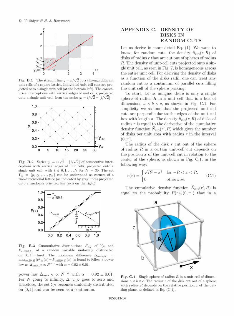
Let us derive in more detail Eq. (1). We want toknow, for random cuts, the density ncut(r,R) ofdisks of radius r that are cut out of spheres of radiusR. The density of unit-cell cuts projected onto a sin-gle unit cell, as seen in Fig. 7, is homogeneous acrossthe entire unit cell. For deriving the density of disksas a function of the disks radii, one can treat anyrandom cut as a continuum of parallel cuts fillingthe unit cell of the sphere packing.
To start, let us imagine there is only a singlesphere of radius R in a unit cell that is a box ofdimensions a × b × c, as shown in Fig. C.1. Forsimplicity we assume that the projected unit-cellcuts are perpendicular to the edges of the unit-cellbox with length a. The density ncut(r,R) of disks ofradius r is equal to the derivative of the cumulativedensity function Ncut(r′, R) which gives the numberof disks per unit area with radius r in the interval(0, r′].
The radius of the disk r cut out of the sphereof radius R in a certain unit-cell cut depends onthe position x of the unit-cell cut in relation to thecenter of the sphere, as shown in Fig. C.1, in thefollowing way:
r(x) =
{√R2 − x2 for −R < x < R,
0 otherwise.(C.1)
The cumulative density function Ncut(r′, R) isequal to the probability P (r∈ (0, r′]) that in a
Fig. C.1 Single sphere of radius R in a unit cell of dimen-sions a × b × c. The radius r of the disk cut out of a spherewith radius R depends on the relative position x of the cut-ting plane, as defined in Eq. (C.1).
1850013-14

February 2, 2018 14:1 0218-348X1850013
Cutting Self-Similar Space-Filling Sphere Packings
random unit-cell cut a disk of radius r in theinterval (0, r′] exists, divided by the area b × c ofthe unit-cell cut. From Eq. (C.1), one can followthat r ∈ (0, r′] whenever x ∈ (−R,
√R2 − r′2] ∪
[√
R2 − r′2, R). Because of the homogeneous distri-bution of projected unit-cell cuts, the probabilitydensity of the relative position x in Eq. (C.1) (com-pare with Fig. C.1) is f(x) = 1/a, since the unit-cellhas dimension a along the direction of x (compareFig. C.1). Therefore, we find that
Ncut(r′, R)
=P (r ∈ (0, r′])
bc
=P (x ∈ (−R,−√
R2 − r′2] ∪ [√
R2 − r′2, R))bc
=
∫ −√R2−r′2
−R f(x)dx +∫ R√
R2−r′2 f(x)dx
bc
=
∫ −√R2−r′2
−R1adx +
∫ R√R2−r′2
1adx
bc
=−2R − 2
√R2 − r′2
abc. (C.2)
Using Eq. (C.2), we then find
ncut(r,R) =d(Ncut(r,R))
dr
=2r
abc√
R2 − r2, (C.3)
where we have assumed there exists only a singlesphere of radius R in the unit cell. Given any den-sity n(R) of spheres of radius R in the unit cell, we
(a) (b)
Fig. D.1 Different steps from an original generating setup (a) to a minimal one (d). (b) Reduced setup after consideringmirror lines, i.e. infinitely large inversion circles. (c) Potential inversion circle (dashed, highlighted) that can be found fromthe fact that it maps the two seeds onto each other.
find the number of spheres in the unit-cell box ofdimensions a × b × c to be abc · n(R), such that wefind for the general case
ncut(r,R) =2r
abc√
R2 − r2· abc · n(R)
=2r · n(R)√
R2 − r2. (C.4)
APPENDIX D. TOPOLOGICALCOMPARISON
To judge if two different packings are the sametopology or not, one can carry out a topologicalcomparison. If two generating setups of the differentpackings are topologically equal, these packings arethe same topology. Since a single packing can havedifferent generating setups, one first needs to definea type of setup that is topologically unique for theresulting topology. We define a topologically uniquesetup as the minimal generating setup of a packing,i.e. the setup with the least amount of seeds andinversion spheres needed.
Therefore, we first find from the generatingsetup of each packing a minimal setup. We explainthis procedure at the two-dimensional example inFig. D.1, which can be analogously applied to anyhigher dimension.
We start with the original setup (Fig. D.1a) andfirst find all mirror lines, which in a setup can beused as inversion circles of infinite radii. Seeds areonly allowed to intersect inversion circles, includingmirror lines, perpendicularly, otherwise, they haveto lie outside of them. Therefore, we need to define
1850013-15

February 2, 2018 14:1 0218-348X1850013
D. V. Stager & H. J. Herrmann
(c) (d)
Fig. D.1 (Continued)
which side of the mirror lines we consider as theoutside. We choose an arbitrary point P in spacethat we declare to lie outside of all mirror lines,where P should not lie on a mirror line itself. Wethen neglect every inversion circle and seed that lieinside a mirror line. As shown in Fig. D.1b, thisalready leads to a reduced setup. From there, wecheck if any two inversion circles or any two seedscan be mapped onto each other by a new inversioncircle. If we find such an inversion circle as shownin Fig. D.1c, we add it and iteratively invert everyseed and inversion circle at inversion circles whichthey intersect with an angle larger than π/2. Wedo this to find the largest inverses of each seed andinversion circle which lies outside all mirror lines.
In the resulting setup, certain inversion circlesand seeds might exist multiple times, such that weonly keep a single instance of it. We check if thissetup is valid, i.e. if it fulfills all constraints as dis-cussed in detail in Ref. 31. If it is a valid setup, oneneeds to prove that it leads to the same packingas the original setup. One can do this by invertingevery seed and inversion circle of the original setupiteratively at the inversion circles of the newly pro-posed setup, till one found the largest inverse ofeach original seed and inversion circle which laysoutside of all mirror lines. If every of these largestinverses is equal to a seed or inversion circle ofthe newly proposed setup, respectively, we knowthat the original setup can be generated from thenewly proposed one. Therefore, the newly proposedsetup leads to the same packing as the original one.One needs to continue to try to reduce every newlyaccepted setup the same way, till one cannot minimize it any further, to be sure to have found theminimal setup, as the one shown in Fig. D.1d.
Fig. D.2 Two minimal generating setups (top) are topolog-ically equivalent if one can find a bijection (arrows) betweenthe two connection networks (bottom) of their seeds andinversion circles. Seeds and inversion circles are connected ifthey are tangent or if they intersect. The details of the con-nection, i.e. the intersection angle or the fact that they aretangent, can be seen as a weight or label of the connection.
After having found two minimal setups for twodifferent packings, one can topologically comparethem. The whole topological information lies in thearrangement of the seeds and inversion circles, i.e.in the way they touch and overlap each other. Theseeds and inversion circles form a network, wheretwo elements are connected if they intersect or ifthey are tangent to each other. The kind of connec-tion, i.e. the intersection angle or the fact that theyare tangent, can be seen as a weight or label of theconnection. If one can find a bijection between thetwo networks as shown in Fig. D.2, the two packingsare the same topology, otherwise, they are different.
1850013-16