cumulus linux 101 lab guide - cumulus networks® … · · 2015-03-24this lab guide is intended...
TRANSCRIPT

Cumulus® Linux® Lab Guide Cumulus Linux 101
Use with Cumulus Linux versions 2.5 and later

CUMULUS® L INUX® LAB GUIDE: CUMULUS LINUX 101
Contents
Overview ............................................................................................................................................................... 3 Lab 1: Accessing and Licensing Your Switches .......................................................................................................... 4 Lab 2: Basic Switch Port Configuration ................................................................................................................... 11 Lab 3: Dynamic Routing Using OSPF with IP Addresses ............................................................................................ 21 Lab 4: Dynamic Routing Using OSPF with Unnumbered Interfaces ............................................................................. 28 Lab 5: Using Prescriptive Topology Manager (PTM) .................................................................................................. 33 Lab 2-ALT: Basic Switch Port Configuration (Traditional Bridge Mode) ........................................................................ 36 Version 1.7.3 March 24, 2015 © 2015 Cumulus Networks. CUMULUS, the Cumulus Logo, CUMULUS NETWORKS, and the Rocket Turtle Logo (the “Marks”) are trademarks and service marks of Cumulus Networks, Inc. in the U.S. and other countries. You are not permitted to use the Marks without the prior written consent of Cumulus Networks. The registered trademark Linux® is used pursuant to a sublicense from LMI, the exclusive licensee of Linus Torvalds, owner of the mark on a world-wide basis. All other marks are used under fair use or license from their respective owners.
2

CUMULUS® L INUX® LAB GUIDE: CUMULUS LINUX 101
Overview
Objective This lab guide is intended to give you a basic run-through of the functionality and concepts within Cumulus Linux. Lab Environment The lab exercises are designed to be performed on the Cumulus Workbench (CW) using a two-switch topology. The CW architecture and topology is shown below in Figure 1.
Figure 1. Two Switch CW Environment Overview (Example IP Address—Yours May Vary)
Each CW environment includes a lab workbench (wbench) to connect to from the outside world. From the wbench, you can access two interconnected switches, switch 1 and switch 2, known as leaf1 and leaf2. The wbench has two interfaces, one connected to your switches on the management port and one allowing inbound firewalled access. Additionally, a console server appliance is reachable from the wbench to access the serial consoles of each switch. The components in Figure 1 are numbered to correspond to the steps and methods needed to access your switches—1) the wbench, and from there, 2) use cw-mux to connect to the consoles on both switches. You may perform these exercises in your own, similarly configured, environment using two switches. Sample outputs are provided throughout the lab exercises as illustrative examples, and may differ from what you see within your environment. The labs in this guide are intended to be performed sequentially, as certain labs depend upon actions performed in prior labs. If you skip ahead, you may need to backtrack to perform and complete prerequisite steps. Prerequisites This lab guide assumes you have basic knowledge of networking and Linux, and understand how to use vi to edit files in Linux. For a cheat sheet on vi commands, refer to: http://www.viemu.com/vi-vim-cheat-sheet.gif. Alternatively, you can use nano as a text editor instead of vi—simply substitute “vi” with “nano”. Nano features an on-screen menu of commands for easier navigation. Commands labeled with ^ represent <Ctrl>, e.g. ^X = <Ctrl>+<x>.
3

CUMULUS® L INUX® LAB GUIDE: CUMULUS LINUX 101
Lab 1: Accessing and Licensing Your Switches Objective You will access your switches. In the CW, this involves first connecting to the lab wbench via SSH. From the wbench, you can access a switch either through a console server or directly via SSH. Goals
• Successfully SSH into your lab wbench, and then access a switch via serial console or SSH. • Install the Cumulus Linux license.
Procedure
1. Review the CW access steps and locate your CW login credentials.
There are two steps to get into your switch. Refer to your CW access email for login credentials.
SSH to the wbench. For example, ssh [email protected] (See your email for the exact workbench number and password.)
From the wbench, use cw-mux to connect directly to the consoles on your switches. The process for getting into your switch is shown in greater detail that you can follow in the remaining steps of this lab or you can refer to the Cumulus Workbench User Guide.
Locate your CW login credentials email. Look for the subject, “Cumulus Workbench details for…” A sample email is shown below. Locate the highlighted fields and values in your corresponding email to access your wbench and switch. ================================================================================ From: <[email protected]> Date: Friday, September 26, 2014 12:42 AM To: Recipient Subject: Cumulus Workbench details for CW Reservation Welcome to your dedicated Cumulus Workbench! This lab environment has been provisioned for your exclusive use of Cumulus Linux. This reservation ends on XXX. Your lab environment is remotely accessible and consists of a workbench machine (wbench) and one or more physical switches hosted at Cumulus Networks. 1. Accessing the Lab Environment To access your lab, connect to the wbench via SSH: ssh [email protected] Password: rcc2b9c5 This takes you to the wbench. Once you accept the Cumulus Workbench Terms of Use, you will see a prompt, cumulus@wbench. From here, you can access a Cumulus switch either through a console server or SSH as detailed in step 2. (Alternatively, you can access the wbench from a Web browser - Chrome, Firefox, Safari - at https://workbench.cumulusnetworks.com:6200)
4

CUMULUS® L INUX® LAB GUIDE: CUMULUS LINUX 101
2. Accessing your Cumulus Switch(es) From the wbench, you can access a Cumulus switch through a console server by running cw-mux. cumulus@wbench: ~$ cw-mux Toggle to the Switches window to see your switches. To log into a switch, use the following credentials: User: cumulus Password: CumulusLinux! Alternatively, you can access your switches directly from wbench using SSH, e.g. ssh cumulus@leaf1.
... ================================================================================
2. Open an SSH client, and access the wbench.
• Windows users: Download PuTTY from http://www.chiark.greenend.org.uk/~sgtatham/putty/download.html. • Mac users: Use the Terminal application. • Linux users: Open a Bash shell. Use the connection details in your email for the workbench user and password specific to your environment.
Example: ssh [email protected] [email protected]’s password: <password> cumulus@wbench:~$
or via PuTTY:
The first time you access the CW, you will need to read and acknowledge the Cumulus Workbench Terms of Use in order to continue. You will not be presented with this prompt in subsequent CW logins. Please read these Terms of Use (“Agreement”) carefully before using or obtaining ... (Hit space bar to page through the agreement.) Do you agree to the above terms? [y/n] y Welcome to Ubuntu 12.04.4 LTS (GNU/Linux 3.2.0-61-generic x86_64) cumulus@wbench:~$ You now have an SSH session into the wbench.
5

CUMULUS® L INUX® LAB GUIDE: CUMULUS LINUX 101
3. From the wbench, start cw-mux.
Run the command cw-mux to open up the multi-window display. cumulus@wbench:~$ cw-mux
When cw-mux runs, the terminal becomes a multi-window display, with 5 windows displayed by default. The active window is highlighted in blue.
Window Content
0: Overview Terminal command list (e.g. for toggling between windows)
This is the window you land in by default.
1: Workbench Shell / bash on the local workbench (wbench)
2: Switches
via SSH
Split-pane window, connected via SSH to each switch.
This is the window where you will be spending most of your time for the labs.
To toggle between panes, type <Ctrl>-<b> then o.
(<Ctrl>-<b> then <Ctrl>-o will reverse the order of the panes on the split screen.)
3: Switches
via serial console
Split-pane window, connected to the serial console of each switch.
This window is needed when direct console access is needed, such as going into ONIE during a Cumulus Linux installation.
To toggle between panes, type <Ctrl>-<b> then o.
4: Apache Log Content here is generated by tailing /var/log/apache/access.log. Useful to see ONIE install logging data.
Take note of the navigational commands, as well as the shortcuts to type in “cumulus” and the password “CumulusLinux!”
6

CUMULUS® L INUX® LAB GUIDE: CUMULUS LINUX 101
Terminal session state is preserved should you ever leave and come back.
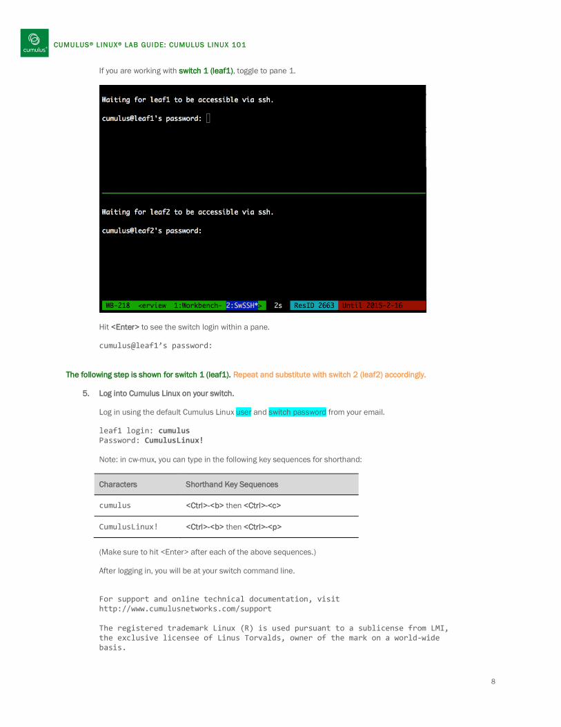
4. From cw-mux, toggle to the Switches window.
Type <Ctrl>-<b> then 2 to display the Switches window. Resize your terminal window to see more screen area as needed.
The Switches window is split into 2 panes. The top pane represents switch 1 (leaf1) and the bottom pane represents switch 2 (leaf2). To toggle between panes, type <Ctrl>-<b> then o. Note: Pressing <Ctrl>-<b> then <Ctrl>-<o> will reorder the panels.
7
CUMULUS® L INUX® LAB GUIDE: CUMULUS LINUX 101
If you are working with switch 1 (leaf1), toggle to pane 1.
Hit <Enter> to see the switch login within a pane. cumulus@leaf1’s password:
The following step is shown for switch 1 (leaf1). Repeat and substitute with switch 2 (leaf2) accordingly.
5. Log into Cumulus Linux on your switch.
Log in using the default Cumulus Linux user and switch password from your email. leaf1 login: cumulus Password: CumulusLinux! Note: in cw-mux, you can type in the following key sequences for shorthand:
Characters Shorthand Key Sequences
cumulus <Ctrl>-<b> then <Ctrl>-<c>
CumulusLinux! <Ctrl>-<b> then <Ctrl>-<p>
(Make sure to hit <Enter> after each of the above sequences.)
After logging in, you will be at your switch command line. For support and online technical documentation, visit http://www.cumulusnetworks.com/support The registered trademark Linux (R) is used pursuant to a sublicense from LMI, the exclusive licensee of Linus Torvalds, owner of the mark on a world-wide basis.
8
CUMULUS® L INUX® LAB GUIDE: CUMULUS LINUX 101
***************************************************************** This installation of Cumulus Linux is not licensed. The front panel ports will not operate. To obtain a license, contact Cumulus Networks: http://cumulusnetworks.com/ ***************************************************************** cumulus@leaf1$
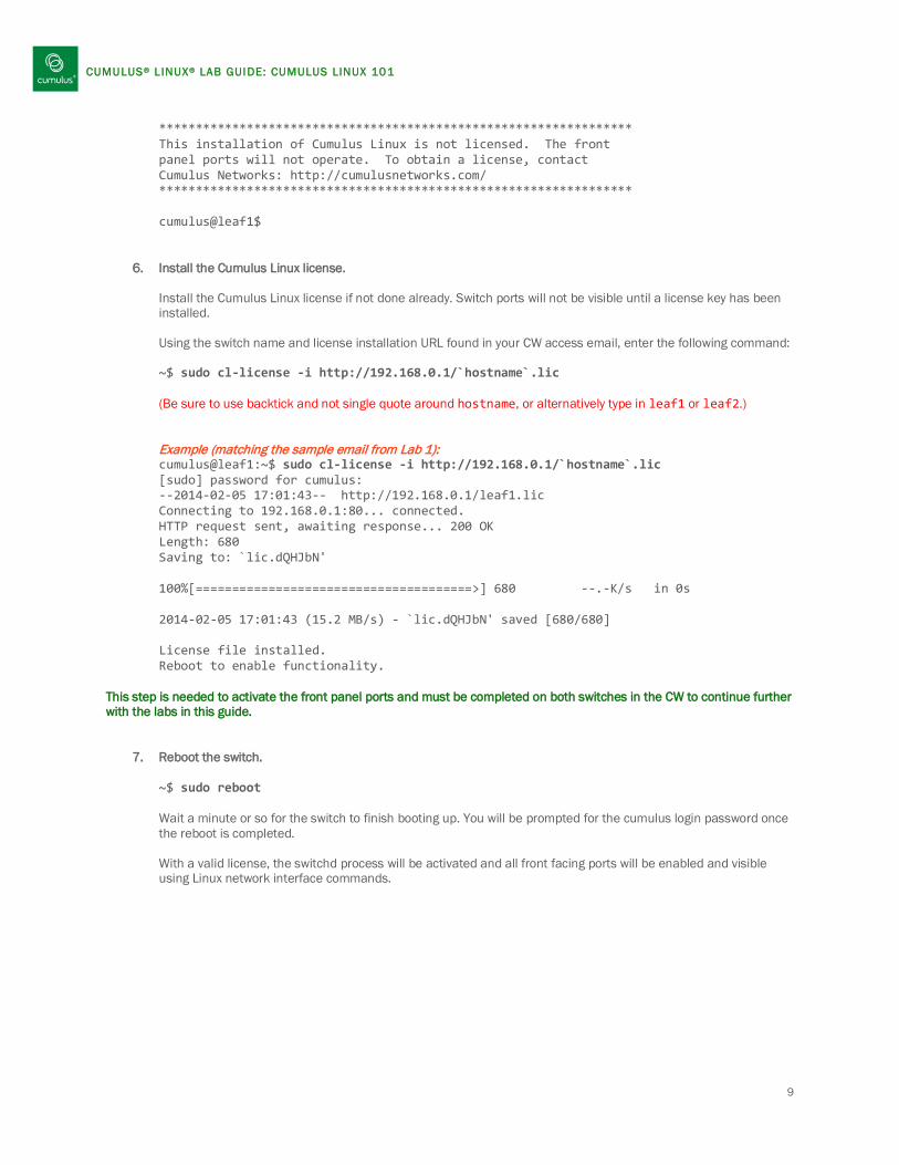
6. Install the Cumulus Linux license. Install the Cumulus Linux license if not done already. Switch ports will not be visible until a license key has been installed. Using the switch name and license installation URL found in your CW access email, enter the following command: ~$ sudo cl-license -i http://192.168.0.1/`hostname`.lic (Be sure to use backtick and not single quote around hostname, or alternatively type in leaf1 or leaf2.)
Example (matching the sample email from Lab 1): cumulus@leaf1:~$ sudo cl-license -i http://192.168.0.1/`hostname`.lic
[sudo] password for cumulus: --2014-02-05 17:01:43-- http://192.168.0.1/leaf1.lic Connecting to 192.168.0.1:80... connected. HTTP request sent, awaiting response... 200 OK Length: 680 Saving to: `lic.dQHJbN' 100%[======================================>] 680 --.-K/s in 0s 2014-02-05 17:01:43 (15.2 MB/s) - `lic.dQHJbN' saved [680/680] License file installed. Reboot to enable functionality.
This step is needed to activate the front panel ports and must be completed on both switches in the CW to continue further with the labs in this guide.
7. Reboot the switch. ~$ sudo reboot Wait a minute or so for the switch to finish booting up. You will be prompted for the cumulus login password once the reboot is completed. With a valid license, the switchd process will be activated and all front facing ports will be enabled and visible using Linux network interface commands.
9

CUMULUS® L INUX® LAB GUIDE: CUMULUS LINUX 101
8. Verify the Cumulus Linux license has been installed. From your switch’s command line, type: ~$ sudo cl-license -----BEGIN PGP SIGNED MESSAGE----- Hash: SHA1 [email protected] account=Cumulus Workbench expires=1396335600 #2014-04-01 serial=D1012023918PE000011 num_licenses=1 NFR=1 need_eula=0 -----BEGIN PGP SIGNATURE----- Version: GnuPG v1.4.10 (GNU/Linux) XQEcBAEBAgAGBQJTE92+AAoJEPxJF1FuRcN0WLUIAMB6P/YpI8T5lKunVu0Am3rR ptzcUYK45WGaNQYKslKACmuzko04LdEz3ttOQCU8GWNXusQaCiiWprcs4+8pfnrt mCWP6I76YCNqZ/9hGP7QJT71ibh16UTKV+UD741uvAEhoVO61+0c4lcRvwMYJRNU YBVzd7EUVXNMYHItFY+emYFDDUzKGm2vuUtXDAD9CfH3HNxx/Kijbod/KmbXEO0u Us2m1T4KZHxWqCuPOw8brFEu6VDNWrfgxaqajxHjc+iRETlq+yjN63beAOYSRlU= =Njkz -----END PGP SIGNATURE-----
This completes Lab 1.
10

CUMULUS® L INUX® LAB GUIDE: CUMULUS LINUX 101
Lab 2: Basic Switch Port Configuration Objective You will define and activate switch port interfaces and basic Layer 2 constructs. The switches in the CW have the first four front panel ports, swp1 through swp4, connected to each other respectively, i.e. swp1 on switch 1 is connected to swp1 on switch 2, etc. The cabling is illustrated below in Figure 2. The link state for each port swp1 through swp4 will be down until each pair of ports is defined and configured on each switch, and after both corresponding ports are brought up. NOTE: This lab is written using the VLAN-aware bridge mode which is available starting in Cumulus Linux 2.5. If you prefer to use the Traditional bridge mode, please use the section labeled Lab 2-ALT: Basic Switch Port Configuration (Traditional Mode Bridge). Goals
• Activate ports swp1 and swp2 on each switch and verify connectivity. • Create an LACP-bonded interface using ports swp1 and swp2. • Create a bridge with two untagged bridge members (access switch ports). • Modify the bridge to add VLAN tagging (trunk port). • Show interface statistics.
Figure 2. Lab Switch Port Cabling Procedure This lab requires you to have previously installed and activated a Cumulus License in Lab 1 in order to see the switch ports (swps).
1. Review interface configuration concepts.
Read the Interfaces chapter in the user guide: http://docs.cumulusnetworks.com/display/CL25/Layer+1+and+2+Features Review the differences between dhcp, static, and manual methods for interfaces in Linux, http://manpages.ubuntu.com/manpages/saucy/man5/interfaces.5.html Review the Linux Ethernet bonding driver information at: https://www.kernel.org/doc/Documentation/networking/bonding.txt Read the Ethernet Bridging (VLANs) chapter in the user guide: http://docs.cumulusnetworks.com/display/CL25/Ethernet+Bridging+-+VLANs
11

CUMULUS® L INUX® LAB GUIDE: CUMULUS LINUX 101
2. Configure and activate two switch ports. Verify connectivity between switches. Define swp1 and swp2 on switch 1. Do the same on switch 2. This results in a topology shown in Figure 3.
Figure 3. Activated swp1 and swp2 leaf1:~$ sudo vi /etc/network/interfaces Add the following lines for swp1 and swp2: auto swp1 iface swp1 auto swp2 iface swp2 Save the /etc/network/interfaces file. (To save the file, type <Esc> :wq! If you had permissions problems saving the file, make sure you used sudo in getting into vi in the first place.) On switch 1, bring up swp1: leaf1:~$ sudo ifup swp1 The link is not yet active. You can verify that with these commands: leaf1:~$ ip link show dev swp1 3: swp1: <NO-CARRIER,BROADCAST,MULTICAST,UP> mtu 1500 qdisc pfifo_fast state DOWN mode DEFAULT qlen 500 link/ether 08:9e:01:f8:95:0d brd ff:ff:ff:ff:ff:ff leaf1:~$ tail /var/log/switchd.log Look for a line: 1421253920.301949 2015-01-14 16:45:20 netlink.c:187 libnl: swp1, family 0, ifi 3, oper down Go to switch 2, configure swp1 and swp2 similarly as above, and bring up swp1. This activates the link.
12

CUMULUS® L INUX® LAB GUIDE: CUMULUS LINUX 101
leaf2:~$ sudo ifup swp1
leaf1:~$ ip link show dev swp1 3: swp1: <BROADCAST,MULTICAST,UP,LOWER_UP> mtu 1500 qdisc pfifo_fast state UP mode DEFAULT qlen 500 link/ether 08:9e:01:f8:95:0d brd ff:ff:ff:ff:ff:ff leaf1:~$ tail /var/log/switchd.log Look for a line: 1421254056.078741 2015-01-14 16:47:36 netlink.c:187 libnl: swp1, family 0, ifi 3, oper up Similarly, bring up swp2 on both switch 1 and bring up swp2 on switch 2. leaf1:~$ sudo ifup swp2 leaf2:~$ sudo ifup swp2
3. Create an LACP port bond (bundle/channel). Assign ports swp1 and swp2 to a bonded interface. This creates a topology as shown below in Figure 4.
Figure 4. LACP Port Bond Add the following stanzas to the /etc/network/interfaces file. Make sure this is done on both switches.
~$ sudo vi /etc/network/interfaces Add the following lines for bond0 on both switch 1 and switch 2: auto bond0 iface bond0 bond-slaves swp1 swp2 bond-mode 802.3ad bond-miimon 100 bond-lacp-rate 1 bond-min-links 1 bond-xmit-hash-policy layer3+4 Note: The stanza for bond0 must come after the stanzas for swp1 and swp2 in the interfaces file. In general, a parent interface—in this case, the bond—must come after the dependent interfaces—the switch ports comprising the bond.
13

CUMULUS® L INUX® LAB GUIDE: CUMULUS LINUX 101
4. Bring up the bonded interface on both switch 1 and switch 2.
~$ sudo ifup bond0 ~$ tail /var/log/syslog Aug 19 01:21:15 cumulus kernel: bonding: bond0 is being created... Aug 19 01:21:15 cumulus kernel: bonding: bond0: setting mode to 802.3ad (4). Aug 19 01:21:15 cumulus kernel: bonding: bond0: Setting MII monitoring interval to 100. Aug 19 01:21:15 cumulus kernel: bonding: bond0: Setting LACP rate to fast (1). Aug 19 01:21:15 cumulus kernel: bonding: bond0: setting xmit hash policy to layer3+4 (1). Aug 19 01:21:15 cumulus kernel: bonding: bond0: Setting min links value to 1 Aug 19 01:21:15 cumulus lldpd[1853]: error while receiving frame on swp2: Network is down Aug 19 01:21:15 cumulus kernel: bonding: bond0: Adding slave swp2. Aug 19 01:21:15 cumulus kernel: bonding: bond0: enslaving swp2 as a backup interface with an up link. Aug 19 01:21:15 cumulus lldpd[1853]: error while receiving frame on swp1: Network is down Aug 19 01:21:15 cumulus kernel: bonding: bond0: Adding slave swp1. Aug 19 01:21:15 cumulus kernel: bonding: bond0: enslaving swp1 as a backup interface with an up link. Aug 19 01:21:15 cumulus kernel: ADDRCONF(NETDEV_UP): bond0: link is not ready Once bond0 has been brought up on both switches, the bond becomes active. Aug 19 01:20:54 cumulus kernel: bonding: bond0: link status definitely up for interface swp1, 1000 Mbps full duplex. Aug 19 01:21:18 cumulus kernel: ADDRCONF(NETDEV_CHANGE): bond0: link becomes ready Aug 19 01:21:19 cumulus kernel: bonding: bond0: link status definitely up for interface swp2, 1000 Mbps full duplex.
14

CUMULUS® L INUX® LAB GUIDE: CUMULUS LINUX 101
5. Check the bond interface status on both switch 1 and switch 2.
~$ cat /proc/net/bonding/bond0 Ethernet Channel Bonding Driver: v3.7.1 (April 27, 2011) Bonding Mode: IEEE 802.3ad Dynamic link aggregation Transmit Hash Policy: layer3+4 (1) MII Status: up MII Polling Interval (ms): 100 Up Delay (ms): 0 Down Delay (ms): 0 802.3ad info LACP rate: fast Min links: 1 Aggregator selection policy (ad_select): stable System Identification: 65535 6c:64:1a:00:2a:91 Active Aggregator Info: Aggregator ID: 1 Number of ports: 2 Actor Key: 17 Partner Key: 17 Partner Mac Address: 08:9e:01:f8:88:37 LACP Bypass Info: Allowed: 0 Timeout: 0 Slave Interface: swp1 MII Status: up Speed: 1000 Mbps Duplex: full Link Failure Count: 0 Permanent HW addr: 08:9e:01:f8:95:0d Aggregator ID: 1 LACP bypass priority: 0 Slave queue ID: 0 Slave Interface: swp2 MII Status: up Speed: 1000 Mbps Duplex: full Link Failure Count: 0 Permanent HW addr: 08:9e:01:f8:95:0e Aggregator ID: 1 LACP bypass priority: 0 Slave queue ID: 0
15

CUMULUS® L INUX® LAB GUIDE: CUMULUS LINUX 101
6. Configure a bridge containing three untagged members.
The next steps apply to both leaf 1 and leaf 2.
On switch 1, configure ports swp3, swp5 and swp6 to be members of a bridge called “bridge” by adding the following stanzas to the /etc/network/interfaces file. This creates a topology illustrated in Figure 5.
Figure 5. Bridge with Untagged Members
leaf1:~$ sudo vi /etc/network/interfaces auto swp3 iface swp3 auto swp5 iface swp5 auto swp6 iface swp6 auto bridge iface bridge bridge-vlan-aware yes bridge-ports swp3 swp5 swp6 bridge-pvid 1 bridge-stp on leaf1:~$ sudo ifreload -a Note: swp5 and swp6 may not be connected in some CW environments, and you may see error messages in syslog accordingly. Aug 19 01:31:09 cumulus kernel: device swp6 entered promiscuous mode Aug 19 01:31:09 cumulus kernel: device swp5 entered promiscuous mode Aug 19 01:31:09 cumulus kernel: ADDRCONF(NETDEV_UP): bridge: link is not ready
16
CUMULUS® L INUX® LAB GUIDE: CUMULUS LINUX 101
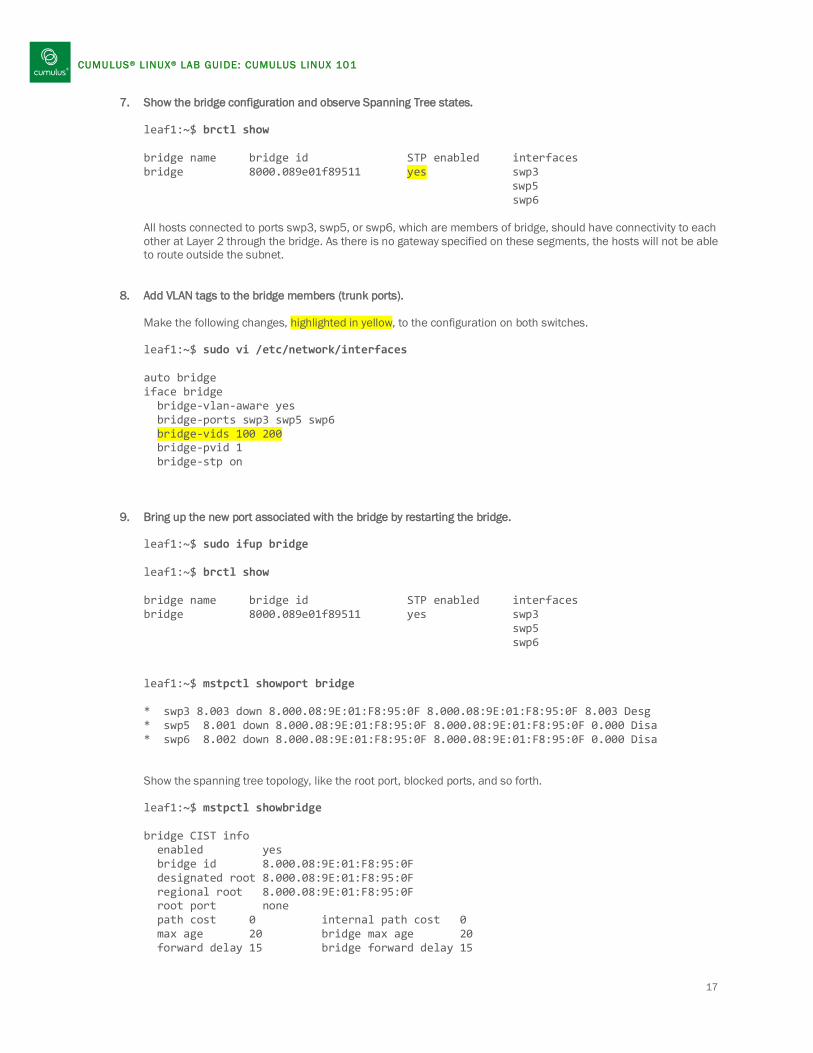
7. Show the bridge configuration and observe Spanning Tree states. leaf1:~$ brctl show bridge name bridge id STP enabled interfaces bridge 8000.089e01f89511 yes swp3
swp5 swp6 All hosts connected to ports swp3, swp5, or swp6, which are members of bridge, should have connectivity to each other at Layer 2 through the bridge. As there is no gateway specified on these segments, the hosts will not be able to route outside the subnet.
8. Add VLAN tags to the bridge members (trunk ports).
Make the following changes, highlighted in yellow, to the configuration on both switches.
leaf1:~$ sudo vi /etc/network/interfaces auto bridge iface bridge bridge-vlan-aware yes bridge-ports swp3 swp5 swp6 bridge-vids 100 200 bridge-pvid 1 bridge-stp on
9. Bring up the new port associated with the bridge by restarting the bridge. leaf1:~$ sudo ifup bridge leaf1:~$ brctl show bridge name bridge id STP enabled interfaces bridge 8000.089e01f89511 yes swp3 swp5 swp6
leaf1:~$ mstpctl showport bridge * swp3 8.003 down 8.000.08:9E:01:F8:95:0F 8.000.08:9E:01:F8:95:0F 8.003 Desg * swp5 8.001 down 8.000.08:9E:01:F8:95:0F 8.000.08:9E:01:F8:95:0F 0.000 Disa * swp6 8.002 down 8.000.08:9E:01:F8:95:0F 8.000.08:9E:01:F8:95:0F 0.000 Disa Show the spanning tree topology, like the root port, blocked ports, and so forth. leaf1:~$ mstpctl showbridge bridge CIST info enabled yes bridge id 8.000.08:9E:01:F8:95:0F designated root 8.000.08:9E:01:F8:95:0F regional root 8.000.08:9E:01:F8:95:0F root port none path cost 0 internal path cost 0 max age 20 bridge max age 20 forward delay 15 bridge forward delay 15
17

CUMULUS® L INUX® LAB GUIDE: CUMULUS LINUX 101
tx hold count 6 max hops 20 hello time 2 ageing time 300 force protocol version rstp time since topology change 262s topology change count 1 topology change no topology change port swp3 last topology change port None
18

CUMULUS® L INUX® LAB GUIDE: CUMULUS LINUX 101
BONUS Exercises
10. Show low-level stats on interface swp1. ~$ sudo ethtool -S swp1 NIC statistics: HwIfInOctets: 7854 HwIfInUcastPkts: 0 HwIfInBcastPkts: 0 HwIfInMcastPkts: 85 HwIfOutOctets: 8060 HwIfOutUcastPkts: 0 HwIfOutMcastPkts: 87 HwIfOutBcastPkts: 0 HwIfInDiscards: 0 HwIfInL3Drops: 0 HwIfInBufferDrops: 0 HwIfInAclDrops: 1 HwIfInDot3LengthErrors: 0 HwIfInErrors: 0 SoftInErrors: 0 SoftInDrops: 0 SoftInFrameErrors: 0 HwIfOutDiscards: 0 HwIfOutErrors: 0 HwIfOutQDrops: 0 HwIfOutNonQDrops: 0 SoftOutErrors: 0 SoftOutDrops: 0 SoftOutTxFifoFull: 0 HwIfOutQLen: 0 ... Show LLDP neighbors. ~$ sudo lldpcli show neighbors The example output is for switch 1 (leaf1), showing the neighbor, switch 2 (leaf 2). ------------------------------------------------------------------------------- LLDP neighbors: ------------------------------------------------------------------------------- Interface: eth0, via: LLDP, RID: 1, Time: 0 day, 00:39:59 Chassis: ChassisID: mac 6c:64:1a:00:2e:7f SysName: colo-tor-3 SysDescr: Cumulus Linux MgmtIP: 100.64.3.4 Capability: Bridge, on Capability: Router, on Port: PortID: ifname swp41 PortDescr: swp41 ------------------------------------------------------------------------------- Interface: swp1, via: LLDP, RID: 3, Time: 0 day, 00:08:27 Chassis: ChassisID: mac 70:72:cf:9c:dd:80 SysName: leaf2 SysDescr: Cumulus Linux version 2.5.0 running on accton as4600_54t MgmtIP: 192.168.0.12 Capability: Bridge, on
19

CUMULUS® L INUX® LAB GUIDE: CUMULUS LINUX 101
Capability: Router, on Port: PortID: ifname swp2 PortDescr: swp2 ------------------------------------------------------------------------------- Interface: swp3, via: LLDP, RID: 3, Time: 0 day, 00:08:14 Chassis: ChassisID: mac 70:72:cf:9c:dd:80 SysName: leaf2 SysDescr: Cumulus Linux version 2.5.0 running on accton as4600_54t MgmtIP: 192.168.0.12 Capability: Bridge, on Capability: Router, on Port: PortID: ifname swp3 PortDescr: swp3 -------------------------------------------------------------------------------
This completes Lab 2.
20

CUMULUS® L INUX® LAB GUIDE: CUMULUS LINUX 101
Lab 3: Dynamic Routing Using OSPF with IP Addresses Objective You will configure dynamic routing between the two switches using OSPF (Open Shortest Path First protocol) over a point-to-point link with IP addresses. You will configure OSPF neighbors in an area between the switches over a bond.
leaf1 leaf2 Interface IP Address Interface IP Address lo 10.2.1.1/32 lo 10.2.1.2/32
bond0 10.1.1.1/30 bond0 10.1.1.2/30
bridge.100 10.3.3.1/24 bridge.200 10.4.4.1/24
Figure 8. Network Topology using OSPF with IP Addresses
Goals
• Configure OSPF neighbors using the Quagga routing suite. • Ping between the 2 bridge interfaces to confirm routing works.
Procedure This lab requires that the bond and bridges have been previously configured as described in Lab 2.
1. Review how Quagga is used in Cumulus Linux. Read the Configuring Quagga chapter in the user guide: http://docs.cumulusnetworks.com/display/CL25/Configuring+Quagga
21

CUMULUS® L INUX® LAB GUIDE: CUMULUS LINUX 101
2. Configure the IP addresses for the loopback (lo), bridge interfaces, and bond on switch 1. The next steps apply specifically to switch 1. Actions specific to switch 2 start at step 3. On switch 1, bring down the interfaces. leaf1:~$ sudo ifdown bond0 leaf1:~$ sudo ifdown bridge Refer to Figure 8 for setting up the IP addresses of the interfaces relative to each switch. Configure the IP addresses for the interfaces on switch 1 by making the highlighted changes. leaf1:~$ sudo vi /etc/network/interfaces auto lo iface lo inet loopback address 10.2.1.1/32 auto bond0 iface bond0 address 10.1.1.1/30 bond-slaves swp1 swp2 bond-mode 802.3ad bond-miimon 100 bond-use-carrier 1 bond-lacp-rate 1 bond-min-links 1 bond-xmit-hash-policy layer3+4 auto bridge.100 iface bridge.100 address 10.3.3.1/24 Start the new loopback interface and restart the bond and bridge interfaces on switch 1. leaf1:~$ sudo ifreload -a
22

CUMULUS® L INUX® LAB GUIDE: CUMULUS LINUX 101
3. Configure the IP addresses for the loopback (lo), bridge interfaces, and bond on switch 2. On switch 2, bring down the interfaces and make the highlighted changes. leaf2:~$ sudo ifdown bond0 leaf2:~$ sudo ifdown bridge leaf2:~$ sudo vi /etc/network/interfaces auto lo iface lo inet loopback address 10.2.1.2/32 auto bond0 iface bond0 address 10.1.1.2/30 bond-slaves swp1 swp2 bond-mode 802.3ad bond-miimon 100 bond-use-carrier 1 bond-lacp-rate 1 bond-min-links 1 bond-xmit-hash-policy layer3+4 auto bridge.200 iface bridge.200 address 10.4.4.1/24 Start the new loopback interface, and restart the bond and bridge interfaces on switch 2. leaf2:~$ sudo ifreload -a
23
CUMULUS® L INUX® LAB GUIDE: CUMULUS LINUX 101
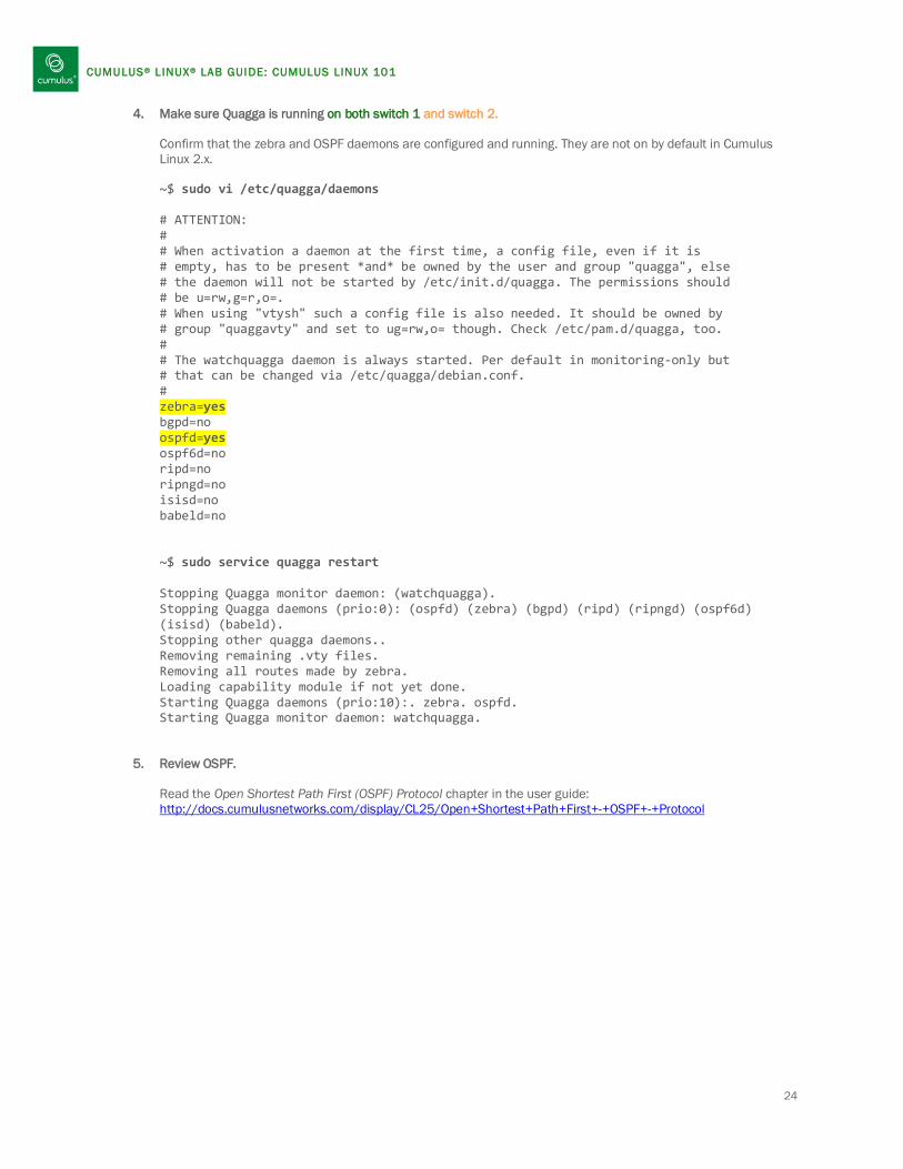
4. Make sure Quagga is running on both switch 1 and switch 2. Confirm that the zebra and OSPF daemons are configured and running. They are not on by default in Cumulus Linux 2.x. ~$ sudo vi /etc/quagga/daemons # ATTENTION: # # When activation a daemon at the first time, a config file, even if it is # empty, has to be present *and* be owned by the user and group "quagga", else # the daemon will not be started by /etc/init.d/quagga. The permissions should # be u=rw,g=r,o=. # When using "vtysh" such a config file is also needed. It should be owned by # group "quaggavty" and set to ug=rw,o= though. Check /etc/pam.d/quagga, too. # # The watchquagga daemon is always started. Per default in monitoring-only but # that can be changed via /etc/quagga/debian.conf. # zebra=yes bgpd=no ospfd=yes ospf6d=no ripd=no ripngd=no isisd=no babeld=no ~$ sudo service quagga restart Stopping Quagga monitor daemon: (watchquagga). Stopping Quagga daemons (prio:0): (ospfd) (zebra) (bgpd) (ripd) (ripngd) (ospf6d) (isisd) (babeld). Stopping other quagga daemons.. Removing remaining .vty files. Removing all routes made by zebra. Loading capability module if not yet done. Starting Quagga daemons (prio:10):. zebra. ospfd. Starting Quagga monitor daemon: watchquagga.
5. Review OSPF. Read the Open Shortest Path First (OSPF) Protocol chapter in the user guide: http://docs.cumulusnetworks.com/display/CL25/Open+Shortest+Path+First+-+OSPF+-+Protocol
24

CUMULUS® L INUX® LAB GUIDE: CUMULUS LINUX 101
6. From the Quagga shell, configure OSPF.
Refer to the previous Figure 8 for setting up the areas and routing. On switch 1, configure OSPF neighbors in Area 0. leaf1:~$ sudo vtysh quagga# configure terminal quagga(config)# router ospf quagga(config-router)# router-id 10.2.1.1 quagga(config-router)# network 10.2.1.1/32 area 0.0.0.0 quagga(config-router)# network 10.1.1.0/30 area 0.0.0.0 quagga(config-router)# redistribute connected Configure point-to-point routing over bond0 and save your configuration. quagga(config-router)# interface bond0 quagga(config-if)# ip ospf network point-to-point quagga(config-if)# exit quagga(config)# exit quagga# write mem Building Configuration... Integrated configuration saved to /etc/quagga/Quagga.conf [OK]
Make the similar configurations on switch 2. leaf2:~$ sudo vtysh quagga# configure terminal quagga(config)# router ospf quagga(config-router)# router-id 10.2.1.2 quagga(config-router)# network 10.2.1.2/32 area 0.0.0.0 quagga(config-router)# network 10.1.1.0/30 area 0.0.0.0 quagga(config-router)# redistribute connected quagga(config-router)# interface bond0 quagga(config-if)# ip ospf network point-to-point quagga(config-if)# exit quagga(config)# exit quagga# write mem Building Configuration... Integrated configuration saved to /etc/quagga/Quagga.conf [OK]
Note: An alternative method to using Quagga shell commands to configure OSPF is to use the non-modal cl-ospf command in the Cumulus Linux CLI.
25

CUMULUS® L INUX® LAB GUIDE: CUMULUS LINUX 101
7. Verify the routes are exchanged correctly. On either switch 1 or switch 2, run the following commands.
quagga# show ip ospf neighbor Output from switch 1: Neighbor ID Pri State Dead Time Address Interface 10.2.1.2 1 Full/DROther 33.882s 10.1.1.2 bond0:10.1.1.1 Output from switch 2: Neighbor ID Pri State Dead Time Address Interface 10.2.1.1 1 Full/DROther 38.939s 10.1.1.1 bond0:10.1.1.2 quagga# show ip ospf database Output from switch 1: OSPF Router with ID (10.2.1.1) Router Link States (Area 0.0.0.0) Link ID ADV Router Age Seq# CkSum Link count 10.2.1.1 10.2.1.1 52 0x80000006 0xbd03 3 10.2.1.2 10.2.1.2 52 0x80000006 0xbb02 3 AS External Link States Link ID ADV Router Age Seq# CkSum Route 10.3.3.0 10.2.1.1 52 0x80000002 0x6a35 E2 10.3.3.0/24 [0x0] 10.4.4.0 10.2.1.2 52 0x80000002 0x4d4f E2 10.4.4.0/24 [0x0] 192.168.0.0 10.2.1.1 52 0x80000002 0x80c5 E2 192.168.0.0/24 [0x0] 192.168.0.0 10.2.1.2 52 0x80000002 0x7aca E2 192.168.0.0/24 [0x0] Output from switch 2: OSPF Router with ID (10.2.1.2) Router Link States (Area 0.0.0.0) Link ID ADV Router Age Seq# CkSum Link count 10.2.1.1 10.2.1.1 170 0x80000007 0xbb04 3 10.2.1.2 10.2.1.2 170 0x80000006 0xbb02 3 AS External Link States Link ID ADV Router Age Seq# CkSum Route 10.3.3.0 10.2.1.1 170 0x80000002 0x6a35 E2 10.3.3.0/24 [0x0] 10.4.4.0 10.2.1.2 170 0x80000002 0x4d4f E2 10.4.4.0/24 [0x0] 192.168.0.0 10.2.1.1 170 0x80000002 0x80c5 E2 192.168.0.0/24 [0x0] 192.168.0.0 10.2.1.2 170 0x80000002 0x7aca E2 192.168.0.0/24 [0x0]
26

CUMULUS® L INUX® LAB GUIDE: CUMULUS LINUX 101
quagga# show ip route Codes: K - kernel route, C - connected, S - static, R - RIP, O - OSPF, I - IS-IS, B - BGP, A - Babel, > - selected route, * - FIB route K>* 0.0.0.0/0 via 192.168.0.1, eth0 O 10.1.1.0/30 [110/10] is directly connected, bond0, 00:04:01 C>* 10.1.1.0/30 is directly connected, bond0 O 10.2.1.1/32 [110/10] is directly connected, lo, 00:04:08 C>* 10.2.1.1/32 is directly connected, lo O>* 10.2.1.2/32 [110/20] via 10.1.1.2, bond0, 00:02:04 C>* 10.3.3.0/24 is directly connected, bridge.100 O>* 10.4.4.0/24 [110/20] via 10.1.1.2, bond0, 00:02:03 C>* 127.0.0.0/8 is directly connected, lo O 192.168.0.0/24 [110/20] via 10.1.1.2, bond0, 00:02:03 C>* 192.168.0.0/24 is directly connected, eth0 quagga# exit ~$ ip route show Output from switch 1: default via 192.168.0.1 dev eth0 10.1.1.0/30 dev bond0 proto kernel scope link src 10.1.1.1 10.2.1.2 via 10.1.1.2 dev bond0 proto zebra metric 20 10.3.3.0/24 dev bridge.100 proto kernel scope link src 10.3.3.1 10.4.4.0/24 via 10.1.1.2 dev bond0 proto zebra metric 20 192.168.0.0/24 dev eth0 proto kernel scope link src 192.168.0.11 Output from switch 2: default via 192.168.0.1 dev eth0 10.1.1.0/30 dev bond0 proto kernel scope link src 10.1.1.2 10.2.1.1 via 10.1.1.1 dev bond0 proto zebra metric 20 10.3.3.0/24 via 10.1.1.1 dev bond0 proto zebra metric 20 10.4.4.0/24 dev bridge.200 proto kernel scope link src 10.4.4.1 192.168.0.0/24 dev eth0 proto kernel scope link src 192.168.0.12 From switch 1: ping from bridge.100 (10.3.3.1) to bridge.200 (10.4.4.1): leaf1:~$ ping -I 10.3.3.1 10.4.4.1 PING 10.4.4.1 (10.4.4.1) from 10.3.3.1 : 56(84) bytes of data. 64 bytes from 10.4.4.1: icmp_req=1 ttl=64 time=0.825 ms 64 bytes from 10.4.4.1: icmp_req=2 ttl=64 time=0.750 ms From switch 2: ping from bridge.200 (10.4.4.1) to bridge.100 (10.3.3.1): leaf2:~$ ping -I 10.4.4.1 10.3.3.1 PING 10.3.3.1 (10.3.3.1) from 10.4.4.1 : 56(84) bytes of data. 64 bytes from 10.3.3.1: icmp_req=1 ttl=64 time=0.740 ms 64 bytes from 10.3.3.1: icmp_req=2 ttl=64 time=1.03 ms 64 bytes from 10.3.3.1: icmp_req=3 ttl=64 time=0.758 ms
This completes Lab 3.
27

CUMULUS® L INUX® LAB GUIDE: CUMULUS LINUX 101
Lab 4: Dynamic Routing Using OSPF with Unnumbered Interfaces Objective You will configure dynamic routing between the two switches using OSPF over a point-to-point link where there are no IP addresses assigned between switches. In the previous lab, you built a topology shown below in Figure 9 with the configured IP addresses.
leaf1 leaf2 Interface IP Address Interface IP Address lo 10.2.1.1/32 lo 10.2.1.2/32
bond0 10.1.1.1/30 bond0 10.1.1.2/30
bridge.100 10.3.3.1/24 bridge.200 10.4.4.1/24
Figure 9. OSPF with IP Addresses You will now change the IP configuration on the bond interfaces from static IP addresses to IP unnumbered. Goals
• Remove existing IP addresses. • Configure OSPF over a point-to-point link with IP unnumbered. • Ping between the two bridge interfaces to confirm routing works.
Procedure This lab requires that the bond and bridges have been previously configured as described in Lab 2, and assumes a dynamic route using OSPF with Area 0 has been previously configured as described in Lab 3.
1. Review OSPF. Read the Open Shortest Path First (OSPF) Protocol chapter in the user guide: http://docs.cumulusnetworks.com/display/CL25/Open+Shortest+Path+First+-+OSPF+-+Protocol
28

CUMULUS® L INUX® LAB GUIDE: CUMULUS LINUX 101
2. From the Quagga shell, configure OSPF.
Refer to Figure 10 below for setting up the areas and routing.
leaf1 leaf2 Interface IP Address Interface IP Address lo 10.2.1.1/32 lo 10.2.1.2/32
bond0 10.2.1.1/32 bond0 10.2.1.2/32
bridge.100 10.3.3.1/24 bridge.200 10.4.4.1/24
Figure 10. OSPF with Unnumbered Interfaces
On switch 1, remove the existing bond0 from Area 0. leaf1:~$ sudo vtysh quagga# configure terminal quagga(config)# router ospf quagga(config-router)# router-id 10.2.1.1 For this router-id change to take effect, save config and restart ospfd quagga(config-router)# no network 10.1.1.0/30 area 0.0.0.0 Configure point-to-point routing over bond0 and save your configuration. quagga(config-router)# interface bond0 quagga(config-if)# ip ospf network point-to-point quagga(config-if)# exit quagga(config)# exit quagga# write mem Building Configuration... Integrated configuration saved to /etc/quagga/Quagga.conf [OK] quagga# exit leaf1:~$ sudo service quagga restart
29

CUMULUS® L INUX® LAB GUIDE: CUMULUS LINUX 101
Change the IP address of bond0 to the same IP address of the loopback, making the bond interface an IP unnumbered interface. Bring down the interface, change the IP address, and restart the interface. leaf1:~$ sudo ifdown bond0 leaf1:~$ sudo vi /etc/network/interfaces
auto bond0 iface bond0 address 10.2.1.1/32 bond-slaves swp1 swp2 bond-mode 802.3ad bond-miimon 100 bond-lacp-rate 1 bond-min-links 1 bond-xmit-hash-policy layer3+4 leaf1:~$ sudo ifup bond0
Make the similar configurations on switch 2. leaf2:~$ sudo vtysh quagga# configure terminal quagga(config)# router ospf quagga(config-router)# router-id 10.2.1.2 quagga(config-router)# no network 10.1.1.0/30 area 0.0.0.0 Configure point-to-point routing over bond0 and save your configuration. quagga(config-router)# interface bond0 quagga(config-if)# ip ospf network point-to-point quagga(config-if)# exit quagga(config)# exit quagga# write mem Building Configuration... Integrated configuration saved to /etc/quagga/Quagga.conf [OK] quagga# exit leaf1:~$ sudo service quagga restart
30
CUMULUS® L INUX® LAB GUIDE: CUMULUS LINUX 101
Change the IP address of bond0 to the same IP address of the loopback, making the bond interface an IP unnumbered interface. Bring down the interface, change the IP address, and restart the interface. leaf2:~$ sudo ifdown bond0 leaf2:~$ sudo vi /etc/network/interfaces
auto bond0 iface bond0 address 10.2.1.2/32 bond-slaves swp1 swp2 bond-mode 802.3ad bond-miimon 100 bond-lacp-rate 1 bond-min-links 1 bond-xmit-hash-policy layer3+4 leaf2:~$ sudo ifup bond0
3. Verify the routes are exchanged correctly. ~$ ip route show Output from switch 1: default via 192.168.0.1 dev eth0 10.2.1.2 via 10.2.1.2 dev bond0 proto zebra metric 20 onlink 10.3.3.0/24 dev bridge.100 proto kernel scope link src 10.3.3.1 10.4.4.0/24 via 10.2.1.2 dev bond0 proto zebra metric 20 onlink 192.168.0.0/24 dev eth0 proto kernel scope link src 192.168.0.11 (Note the missing 10.1.1.0/30 route compared to Lab 3.)
If you do not see all routes, wait a few seconds and issue the ip route show command again. Output from switch 2: default via 192.168.0.1 dev eth0 10.2.1.1 via 10.2.1.1 dev bond0 proto zebra metric 20 onlink 10.3.3.0/24 via 10.2.1.1 dev bond0 proto zebra metric 20 onlink 10.4.4.0/24 dev bridge.200 proto kernel scope link src 10.4.4.1 192.168.0.0/24 dev eth0 proto kernel scope link src 192.168.0.12 (Note the missing 10.1.1.0/30 route compared to Lab 3.) If you do not see all routes, wait a few seconds and issue the ip route show command again.
31

CUMULUS® L INUX® LAB GUIDE: CUMULUS LINUX 101
4. Verify proper routing between switch 1 and switch 2.
After both switches are properly configured, ping between the two bridge interfaces. Use the source interface ping option to ensure the ping is sourced from the bridge interface and not the bond interface.
From switch 1, ping from bridge.100 (10.3.3.1) to bridge.200 (10.4.4.1). leaf1:~$ ping -I 10.3.3.1 10.4.4.1 PING 10.4.4.1 (10.4.4.1) from 10.3.3.1 : 56(84) bytes of data. 64 bytes from 10.4.4.1: icmp_req=1 ttl=64 time=0.099 ms 64 bytes from 10.4.4.1: icmp_req=2 ttl=64 time=0.053 ms From switch 2, ping from bridge.200 (10.4.4.1) to bridge.100 (10.3.3.1). leaf2:~$ ping -I 10.4.4.1 10.3.3.1 PING 10.3.3.1 (10.3.3.1) from 10.4.4.1 : 56(84) bytes of data. 64 bytes from 10.3.3.1: icmp_req=1 ttl=64 time=0.780 ms 64 bytes from 10.3.3.1: icmp_req=2 ttl=64 time=1.01 ms
This completes Lab 4.
32

CUMULUS® L INUX® LAB GUIDE: CUMULUS LINUX 101
Lab 5: Using Prescriptive Topology Manager (PTM) Objective In this lab, you will use the Prescriptive Topology Manager (PTM) tool to verify cabling and configuration. PTM runs as a daemon on each switch. It uses a source topology file in the graphviz-DOT format to verify the physical cabling topology matches the intended design. Further information is available in the Prescriptive Topology Manager (PTM) chapter of the user guide at: http://docs.cumulusnetworks.com/display/CL25/Prescriptive+Topology+Manager+-+PTM Goal
• Use PTM to verify neighbor information and cabling is correct. Procedure This lab requires that swp1 and swp2 have been previously configured and brought up as described in Lab 2.
1. From either switch 1 or switch 2, create a new file in your home folder named “topology.dot”. ~$ cd ~$ vi topology.dot Add the following topology information in the file. You can also use a .dot-compliant tool to create the file. digraph G { graph [hostidtype="hostname", version="1:0", date="01/14/2015"]; "leaf1":"swp1" -> "leaf2":"swp1"; "leaf1":"swp2" -> "leaf2":"swp2"; "leaf1":"swp10" -> "leaf2":"swp10"; } This file represents the topology shown in Figure 11.
Figure 11. Cabling Topology Note: swp10 is not connected in the topology and is included in the file to demonstrate the error case.
2. Place the topology.dot file in the configuration directory used by PTM.
~$ sudo cp topology.dot /etc/ptm.d/
33

CUMULUS® L INUX® LAB GUIDE: CUMULUS LINUX 101
3. Securely copy the topology.dot file to the other switch to ensure both copies match.
If you were on switch 1: leaf1:~$ scp topology.dot cumulus@leaf2:. leaf1:~$ ssh cumulus@leaf2 (or toggle to leaf2 if using the cw-mux split pane Switch window) ---- leaf2:~$ cd leaf2:~$ sudo cp topology.dot /etc/ptm.d/ If you were on switch 2: leaf2:~$ scp topology.dot cumulus@leaf1:. leaf2:~$ ssh cumulus@leaf1 (or toggle to leaf1 if using the cw-mux split pane Switch window) ---- leaf1:~$ cd leaf1:~$ sudo cp topology.dot /etc/ptm.d/
4. On both switch 1 and switch 2, restart the PTM daemon to apply the topology.dot file. ~$ sudo service ptmd restart Restarting Prescriptive Topology Daemon: ptmd.
5. On both switch 1 and switch 2, run ptmctl. Run the PTM client. From switch 1, leaf1:~$ ptmctl -------------------------------------------------------------------------------- port cbl BFD BFD status status peer -------------------------------------------------------------------------------- swp1 pass N/A N/A swp2 pass N/A N/A swp10 fail N/A N/A A status of “pass” means the LLDP neighbor information matches the topology.dot. If the link for swp1 or swp2 is down, you will see a status of “fail” instead, as displayed for swp10. From switch 2, leaf2:~$ ptmctl -------------------------------------------------------------------------------- port cbl BFD BFD status status peer -------------------------------------------------------------------------------- swp1 pass N/A N/A swp2 pass N/A N/A swp10 fail N/A N/A
34

CUMULUS® L INUX® LAB GUIDE: CUMULUS LINUX 101
If you made a typo in the topology.dot file, you may receive the following error. ~$ ptmctl -------------------------------------------------------------------------------- cmd error -------------------------------------------------------------------------------- get-status No valid topology file. Check /etc/ptm.d/topology.dot A common typo mistake is a missing pair of quotes, swapping out a double quote for a single quote, or missing the last bracket.
6. Retrieve LLDP information. On both switch 1 and switch 2, run ptmctl.
Run the PTM client using the –l option. From switch 1, leaf1:~$ ptmctl -l -------------------------------------------------------------------------------- port sysname portID port match last descr on upd -------------------------------------------------------------------------------- swp1 leaf2 swp1 swp1 IfName 8s swp2 leaf2 swp2 swp2 IfName 8s From switch 2, leaf1:~$ ptmctl -l -------------------------------------------------------------------------------- port sysname portID port match last descr on upd -------------------------------------------------------------------------------- swp1 leaf1 swp1 swp1 IfName 8s swp2 leaf1 swp2 swp2 IfName 8s
This completes Lab 5.
35

CUMULUS® L INUX® LAB GUIDE: CUMULUS LINUX 101
Lab 2-ALT: Basic Switch Port Configuration (Traditional Bridge Mode) Objective You will define and activate switch port interfaces and basic Layer 2 constructs. The switches in the CW have the first four front panel ports, swp1 through swp4, connected to each other respectively, i.e. swp1 on switch 1 is connected to swp1 on switch 2, etc. The cabling is illustrated below in Figure 2. The link state for each port swp1 through swp4 will be down until each pair of ports is defined and configured on each switch, and after both corresponding ports are brought up. Goals
• Activate ports swp1 and swp2 on each switch and verify connectivity. • Create an LACP-bonded interface using ports swp1 and swp2. • Create a bridge with two untagged bridge members (access switch ports). • Modify the bridge to add VLAN tagging (trunk port). • Show interface statistics.
Figure 12. Lab Switch Port Cabling Procedure This lab requires you to have previously installed and activated a Cumulus License in Lab 1 in order to see the switch ports (swps).
11. Review interface configuration concepts.
Read the Interfaces chapter in the user guide: http://docs.cumulusnetworks.com/display/CL25/Layer+1+and+2+Features Review the differences between dhcp, static, and manual methods for interfaces in Linux, http://manpages.ubuntu.com/manpages/saucy/man5/interfaces.5.html Review the Linux Ethernet bonding driver information at: https://www.kernel.org/doc/Documentation/networking/bonding.txt Read the Ethernet Bridging (VLANs) chapter in the user guide: http://docs.cumulusnetworks.com/display/CL25/Ethernet+Bridging+-+VLANs
36
CUMULUS® L INUX® LAB GUIDE: CUMULUS LINUX 101
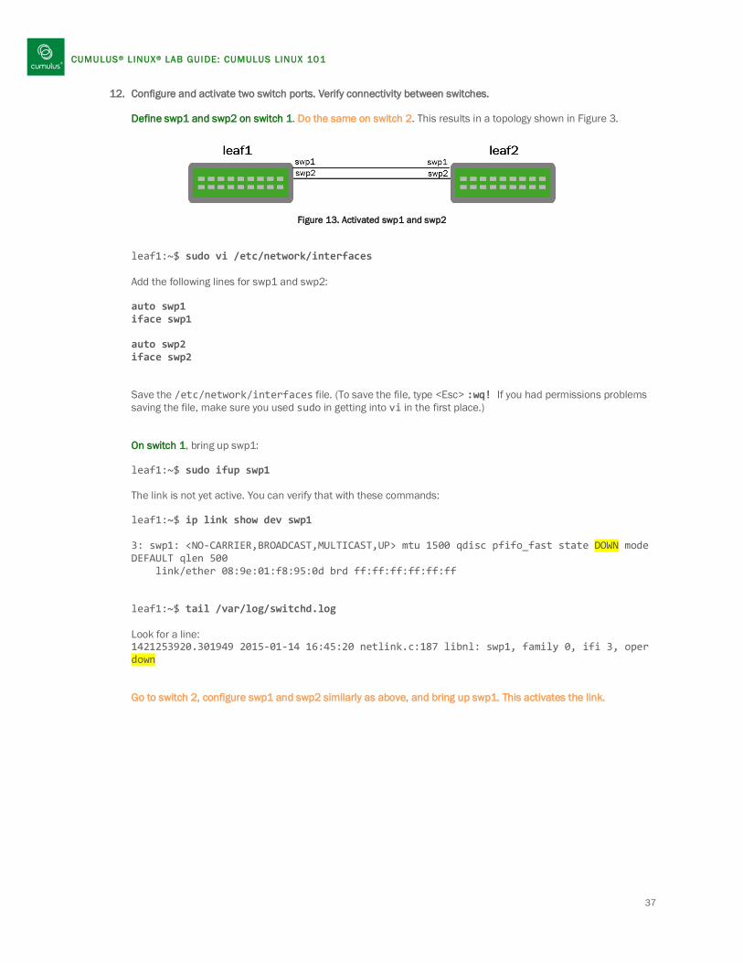
12. Configure and activate two switch ports. Verify connectivity between switches. Define swp1 and swp2 on switch 1. Do the same on switch 2. This results in a topology shown in Figure 3.
Figure 13. Activated swp1 and swp2 leaf1:~$ sudo vi /etc/network/interfaces Add the following lines for swp1 and swp2: auto swp1 iface swp1 auto swp2 iface swp2 Save the /etc/network/interfaces file. (To save the file, type <Esc> :wq! If you had permissions problems saving the file, make sure you used sudo in getting into vi in the first place.) On switch 1, bring up swp1: leaf1:~$ sudo ifup swp1 The link is not yet active. You can verify that with these commands: leaf1:~$ ip link show dev swp1 3: swp1: <NO-CARRIER,BROADCAST,MULTICAST,UP> mtu 1500 qdisc pfifo_fast state DOWN mode DEFAULT qlen 500 link/ether 08:9e:01:f8:95:0d brd ff:ff:ff:ff:ff:ff leaf1:~$ tail /var/log/switchd.log Look for a line: 1421253920.301949 2015-01-14 16:45:20 netlink.c:187 libnl: swp1, family 0, ifi 3, oper down Go to switch 2, configure swp1 and swp2 similarly as above, and bring up swp1. This activates the link.
37

CUMULUS® L INUX® LAB GUIDE: CUMULUS LINUX 101
leaf2:~$ sudo ifup swp1
leaf1:~$ ip link show dev swp1 3: swp1: <BROADCAST,MULTICAST,UP,LOWER_UP> mtu 1500 qdisc pfifo_fast state UP mode DEFAULT qlen 500 link/ether 08:9e:01:f8:95:0d brd ff:ff:ff:ff:ff:ff leaf1:~$ tail /var/log/switchd.log Look for a line: 1421254056.078741 2015-01-14 16:47:36 netlink.c:187 libnl: swp1, family 0, ifi 3, oper up Similarly, bring up swp2 on both switch 1 and bring up swp2 on switch 2. leaf1:~$ sudo ifup swp2 leaf2:~$ sudo ifup swp2
13. Create an LACP port bond (bundle/channel). Assign ports swp1 and swp2 to a bonded interface. This creates a topology as shown below in Figure 4.
Figure 14. LACP Port Bond Add the following stanzas to the /etc/network/interfaces file. Make sure this is done on both switches.
~$ sudo vi /etc/network/interfaces Add the following lines for bond0 on both switch 1 and switch 2: auto bond0 iface bond0 bond-slaves swp1 swp2 bond-mode 802.3ad bond-miimon 100 bond-lacp-rate 1 bond-min-links 1 bond-xmit-hash-policy layer3+4 Note: The stanza for bond0 must come after the stanzas for swp1 and swp2 in the interfaces file. In general, a parent interface—in this case, the bond—must come after the dependent interfaces—the switch ports comprising the bond.
38

CUMULUS® L INUX® LAB GUIDE: CUMULUS LINUX 101
14. Bring up the bonded interface on both switch 1 and switch 2.
~$ sudo ifup bond0 ~$ tail /var/log/syslog Aug 19 01:21:15 cumulus kernel: bonding: bond0 is being created... Aug 19 01:21:15 cumulus kernel: bonding: bond0: setting mode to 802.3ad (4). Aug 19 01:21:15 cumulus kernel: bonding: bond0: Setting MII monitoring interval to 100. Aug 19 01:21:15 cumulus kernel: bonding: bond0: Setting LACP rate to fast (1). Aug 19 01:21:15 cumulus kernel: bonding: bond0: setting xmit hash policy to layer3+4 (1). Aug 19 01:21:15 cumulus kernel: bonding: bond0: Setting min links value to 1 Aug 19 01:21:15 cumulus lldpd[1853]: error while receiving frame on swp2: Network is down Aug 19 01:21:15 cumulus kernel: bonding: bond0: Adding slave swp2. Aug 19 01:21:15 cumulus kernel: bonding: bond0: enslaving swp2 as a backup interface with an up link. Aug 19 01:21:15 cumulus lldpd[1853]: error while receiving frame on swp1: Network is down Aug 19 01:21:15 cumulus kernel: bonding: bond0: Adding slave swp1. Aug 19 01:21:15 cumulus kernel: bonding: bond0: enslaving swp1 as a backup interface with an up link. Aug 19 01:21:15 cumulus kernel: ADDRCONF(NETDEV_UP): bond0: link is not ready Once bond0 has been brought up on both switches, the bond becomes active. Aug 19 01:20:54 cumulus kernel: bonding: bond0: link status definitely up for interface swp1, 1000 Mbps full duplex. Aug 19 01:21:18 cumulus kernel: ADDRCONF(NETDEV_CHANGE): bond0: link becomes ready Aug 19 01:21:19 cumulus kernel: bonding: bond0: link status definitely up for interface swp2, 1000 Mbps full duplex.
39
CUMULUS® L INUX® LAB GUIDE: CUMULUS LINUX 101
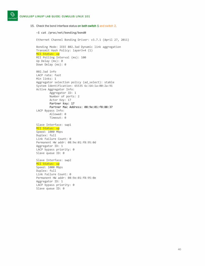
15. Check the bond interface status on both switch 1 and switch 2.
~$ cat /proc/net/bonding/bond0 Ethernet Channel Bonding Driver: v3.7.1 (April 27, 2011) Bonding Mode: IEEE 802.3ad Dynamic link aggregation Transmit Hash Policy: layer3+4 (1) MII Status: up MII Polling Interval (ms): 100 Up Delay (ms): 0 Down Delay (ms): 0 802.3ad info LACP rate: fast Min links: 1 Aggregator selection policy (ad_select): stable System Identification: 65535 6c:64:1a:00:2a:91 Active Aggregator Info: Aggregator ID: 1 Number of ports: 2 Actor Key: 17 Partner Key: 17 Partner Mac Address: 08:9e:01:f8:88:37 LACP Bypass Info: Allowed: 0 Timeout: 0 Slave Interface: swp1 MII Status: up Speed: 1000 Mbps Duplex: full Link Failure Count: 0 Permanent HW addr: 08:9e:01:f8:95:0d Aggregator ID: 1 LACP bypass priority: 0 Slave queue ID: 0 Slave Interface: swp2 MII Status: up Speed: 1000 Mbps Duplex: full Link Failure Count: 0 Permanent HW addr: 08:9e:01:f8:95:0e Aggregator ID: 1 LACP bypass priority: 0 Slave queue ID: 0
40

CUMULUS® L INUX® LAB GUIDE: CUMULUS LINUX 101
16. Configure a bridge containing two untagged members (switch access ports).
The next steps apply specifically to switch 1. Actions specific to switch 2 start at step 10.
On switch 1, configure ports swp5 and swp6 to be members of bridge bridge.100 by adding the following stanzas to the /etc/network/interfaces file. This creates a topology illustrated in Figure 5.
Figure 15. Bridge with Untagged Members
leaf1:~$ sudo vi /etc/network/interfaces auto swp5 iface swp5 auto swp6 iface swp6 auto br-vlan100 iface br-vlan100 bridge-ports swp5 swp6 bridge-stp on leaf1:~$ sudo ifup br-vlan100 Note: swp5 and swp6 may not be connected in some CW environments, and you may see error messages in syslog accordingly. Aug 19 01:31:09 cumulus kernel: device swp6 entered promiscuous mode Aug 19 01:31:09 cumulus kernel: device swp5 entered promiscuous mode Aug 19 01:31:09 cumulus kernel: ADDRCONF(NETDEV_UP): br-vlan100: link is not ready
17. Show the bridge configuration and observe Spanning Tree states. leaf1:~$ brctl show bridge name bridge id STP enabled interfaces br-vlan100 8000.089e01f89511 yes swp5 swp6 All hosts connected to either port swp5 or swp6, which are members of br-vlan100, should have connectivity to each other at Layer 2 through the bridge. As there is no gateway specified on these segments, the hosts will not be able to route outside the subnet.
41

CUMULUS® L INUX® LAB GUIDE: CUMULUS LINUX 101
18. Add a tagged bridge member (trunk port) to the bridge.
Continuing on switch 1, configure port swp3. Then configure subinterface swp3.100 to be a member of bridge br-vlan100 by adding the following stanzas to the /etc/network/interfaces file. Creating the subinterface swp3.100 in the bridge turns swp3 into a trunk port. This creates a topology illustrated in Figure 6.
Figure 16. Bridge with Untagged and Tagged Members
Note: A bridge name can be any string, like “br-vlan100.” It can be helpful to use a bridge name that contains the common dot1q tag number used by the bridge members. For example, naming a bridge “br-vlan100” conveys that the bridge is passing tags with VLAN ID 100. However, the name of a bridge has no direct control of what VLAN tag ID actually passes through, so a bridge named br-vlan100 could be passing tags with VLAN ID 50 if configured as such, although the bridge’s name would be counter-intuitive. Make the following changes, highlighted in yellow, to your configuration.
leaf1:~$ sudo vi /etc/network/interfaces auto swp3 iface swp3 auto br-vlan100 iface br-vlan100 bridge-ports swp5 swp6 swp3.100 bridge-stp on Bring up the swp3 interface. leaf1:~$ sudo ifup swp3
42

CUMULUS® L INUX® LAB GUIDE: CUMULUS LINUX 101
19. Bring up the new port associated with the bridge by restarting the bridge. leaf1:~$ sudo ifup br-vlan100 leaf1:~$ brctl show bridge name bridge id STP enabled interfaces br-vlan100 8000.089e01f89511 yes swp3.100 swp5 swp6
leaf1:~$ mstpctl showport br-vlan100 swp3.100 8.003 down 8.000.08:9E:01:F8:95:0F 8.000.08:9E:01:F8:95:0F 8.003 Desg * swp5 8.001 down 8.000.08:9E:01:F8:95:0F 8.000.08:9E:01:F8:95:0F 0.000 Disa * swp6 8.002 down 8.000.08:9E:01:F8:95:0F 8.000.08:9E:01:F8:95:0F 0.000 Disa (swp3.100 may show up as down. If swp3 is brought up on switch 2, it will show: E swp3.100 8.003 forw 8.000.08:9E:01:F8:95:0F 8.000.08:9E:01:F8:95:0F 8.003 Desg) Show the spanning tree topology, like the root port, blocked ports, and so forth. leaf1:~$ mstpctl showbridge br-vlan100 CIST info enabled yes bridge id 8.000.08:9E:01:F8:95:0F designated root 8.000.08:9E:01:F8:95:0F regional root 8.000.08:9E:01:F8:95:0F root port none path cost 0 internal path cost 0 max age 20 bridge max age 20 forward delay 15 bridge forward delay 15 tx hold count 6 max hops 20 hello time 2 ageing time 300 force protocol version rstp time since topology change 262s topology change count 0 topology change no topology change port None last topology change port None
43

CUMULUS® L INUX® LAB GUIDE: CUMULUS LINUX 101
20. Configure a similar bridge on switch 2. Instead of br-vlan100, switch 2 will have a bridge br-vlan200with swp5, swp6, and swp3.200 (instead of swp3.100) as shown in Figure 7.
Figure 17. Bridge with Untagged and Tagged Members Add the following lines to your configuration. The highlighted text indicates differences in configuration from leaf1. leaf2:~$ sudo vi /etc/network/interfaces auto swp3 iface swp3 auto swp5 iface swp5 auto swp6 iface swp6 auto br-vlan200 iface br-vlan200 bridge-ports swp5 swp6 swp3.200 bridge-stp on Bring up the swp3 interface before starting the br-vlan200 interface. leaf2:~$ sudo ifup swp3 leaf2:~$ sudo ifup br-vlan200 Observe spanning tree states. leaf2:~$ brctl show bridge name bridge id STP enabled interfaces br-vlan200 8000.00e0ec257d7b yes swp3.200 swp5 swp6
leaf2:~$ mstpctl showport br-vlan200
44

CUMULUS® L INUX® LAB GUIDE: CUMULUS LINUX 101
* swp3.200 8.003 down 8.000.00:E0:EC:25:7D:7B 8.000.00:E0:EC:25:7D:7B 8.003 Desg * swp5 8.001 down 8.000.00:E0:EC:25:7D:7B 8.000.00:E0:EC:25:7D:7B 0.000 Disa * swp6 8.002 down 8.000.00:E0:EC:25:7D:7B 8.000.00:E0:EC:25:7D:7B 0.000 Disa (swp3.200 may show up as down. If swp3 is brought up on switch 1, it will show: E swp3.200 8.003 forw 8.000.00:E0:EC:25:7D:7B 8.000.00:E0:EC:25:7D:7B 8.003 Desg) Show the spanning tree topology, like the root port, blocked ports, and so forth. leaf2:~$ mstpctl showbridge br-vlan200 CIST info enabled yes bridge id 8.000.00:E0:EC:25:7D:7B designated root 8.000.00:E0:EC:25:7D:7B regional root 8.000.00:E0:EC:25:7D:7B root port none path cost 0 internal path cost 0 max age 20 bridge max age 20 forward delay 15 bridge forward delay 15 tx hold count 6 max hops 20 hello time 2 ageing time 300 force protocol version rstp time since topology change 289s topology change count 1 topology change no topology change port swp3.200 last topology change port None
This completes Lab 2-ALT.
45