csiro cfd - computational fluid dynamics information and
TRANSCRIPT
Second International Conference on CFD in the Minerals and Process IndustriesCSIRO, Melbourne, Australia6-8 December 1999
141
COMPUTATIONAL MODELLING OF CHAR COMBUSTION BASED ON THESTRUCTURE OF CHAR PARTICLES
Amir EGHLIMI1, Liming LU2, Veena SAHAJWALLA2, David HARRIS3
1 CANCES, Australian Technology Park, Eveleigh, 1430, NSW, Australia2 School of Materials Science and Engineering, The University of New South Wales
Sydney NSW 2052, Australia3 CSIRO Division of Energy Technology, Queensland Centre for Advanced Technologies
2643 Moggill Road, Pinjarra Hills, QLD 4069
ABSTRACT
The successful design and operation of coal combustionsystems depends on the proper application of many facetsof fundamental knowledge. This knowledge isconveniently expressed by the governing equations ofeach particular phenomenon which is relevant to theprocess. It is the main purpose of the fundamentalscientific research in this field to identify the pertinentphysics and chemistry of these phenomena and model thatby solving appropriate transport equations.
In this paper we will particularly consider aspects of charcombustion system modelling which are amenable totreatment by modern computational fluid dynamic codes.Fluent CFD software has been used to model thecombustion of char particle. A diffusion limited rate andthe intrinsic models are employed to model charcombustion. The structure of coal is considered byemploying appropriate shape factor. A Lagrangianapproach is used to trace the particles. The P-1 radiationmodel is used for computing the influence of radiation.The char burnout rate computed based on the abovemodels is then validated against the experimental results.
INTRODUCTION
Coal is one of the cheapest fuels and is available insufficient quantities in Australia. The reserves of higherranking coals, i.e., anthracite and coking bituminous coalsare less as compared to the low ranking bituminous coaland lignite. On the other hand the demand for highranking coals is more for metallurgical use and for use asfuel in power plants. It is expected that high rank coal willlast for about 80 years while the low ranking coal aresufficient for more than 800 years. Because of the cheapprice of coal, so far much attention was not paid toimprove the efficiency of coal consuming equipment.However, the new restrictions on generating “clean”energy have encouraged the designers on manufacturingmore efficient devices. It is estimated that the overallefficiency of coal consuming plants on an average is onlyabout 18%. There is therefore, much scope to improve theefficiency of such equipment. CFD modelling has shownto be an efficient way on modelling pulverised coalcombustion systems (Eghlimi and Sahajwalla, 1997).
Coal is not a homogeneous substance. It is characterisedby wide variations in its properties and compositionincluding the rank of the coal. CFD modelling of
pulverised coal combustion furnaces based on the ultimateand proximate analysis has shown to provide reasonablyaccurate temperature and species concentrationdistribution in a number of applications (Sahajwalla, et al,1997). However, the new challenges in making coalcombustion devices to run more efficiently have madecombustion modelers to consider other parametersinfluencing the combustion process.
To characterise coal, different methods have beenproposed over time. Hensel (1981) presented the coal dataon a moisture and dry ash-free basis. This method had theadvantage that the rank of the coal can be determined bythis comparative method, which eliminates therequirement that bed moisture be accurately known. Withincreasing rank, both aromaticity and molecular clustersize increase (Solum et al., 1989) and the vitrinite of coalalso increases accordingly. The information of the vitrinitereflectance of coal can specify rank, caloric value, volatilematter content and the gas or oil yield of a coal.
Neavel (1981) classified coal according to its grade. Therank, type or petrographic constitution and inorganiccontent of coal affect its value. Coal types can beclassified into seven groups as the following:
1. Chemical analysis, including proximate and ultimateanalysis,
2. Physical properties, including density, porosity andpore structure and surface area,
3. Mechanical properties, namely hardness, elasticity,strength, friability and grindability,
4. Thermal properties including calorific value, heatcapacity, free swelling, agglomerating properties, andthermal conductivity,
5. Electrical properties, including resistivity, electricalconductivity,
6. Ash analysis including ash elemental andmineralogical analysis,
7. Petrograph and vitrinite reflectance.
Commercial CFD codes, more or less include some of theabove characteristics. The following sections identify thecoal properties and discuss the significance of eachspecification. The models available in Fluent CFDsoftware have been used for this modelling.
142
PROBLEM DESCRIPTION
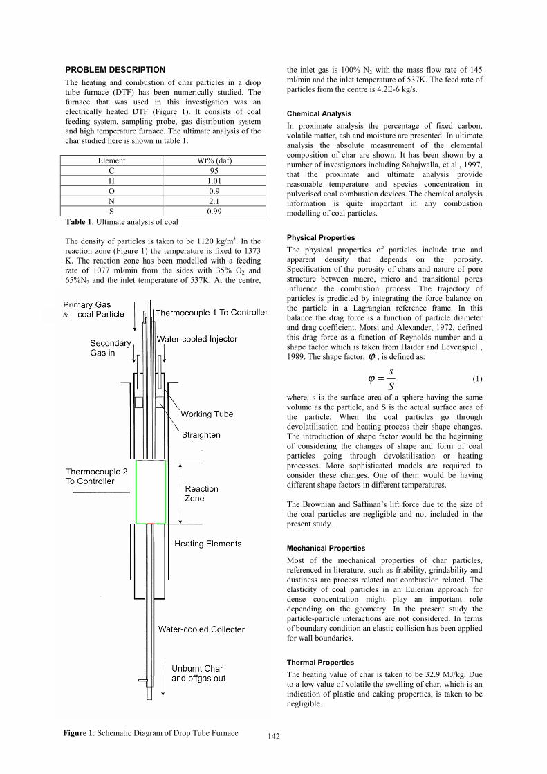
The heating and combustion of char particles in a droptube furnace (DTF) has been numerically studied. Thefurnace that was used in this investigation was anelectrically heated DTF (Figure 1). It consists of coalfeeding system, sampling probe, gas distribution systemand high temperature furnace. The ultimate analysis of thechar studied here is shown in table 1.
Element Wt% (daf)C 95H 1.01O 0.9N 2.1S 0.99
Table 1: Ultimate analysis of coal
The density of particles is taken to be 1120 kg/m3. In thereaction zone (Figure 1) the temperature is fixed to 1373K. The reaction zone has been modelled with a feedingrate of 1077 ml/min from the sides with 35% O2 and65%N2 and the inlet temperature of 537K. At the centre,
the inlet gas is 100% N2 with the mass flow rate of 145ml/min and the inlet temperature of 537K. The feed rate ofparticles from the centre is 4.2E-6 kg/s.
Chemical Analysis
In proximate analysis the percentage of fixed carbon,volatile matter, ash and moisture are presented. In ultimateanalysis the absolute measurement of the elementalcomposition of char are shown. It has been shown by anumber of investigators including Sahajwalla, et al., 1997,that the proximate and ultimate analysis providereasonable temperature and species concentration inpulverised coal combustion devices. The chemical analysisinformation is quite important in any combustionmodelling of coal particles.
Physical Properties
The physical properties of particles include true andapparent density that depends on the porosity.Specification of the porosity of chars and nature of porestructure between macro, micro and transitional poresinfluence the combustion process. The trajectory ofparticles is predicted by integrating the force balance onthe particle in a Lagrangian reference frame. In thisbalance the drag force is a function of particle diameterand drag coefficient. Morsi and Alexander, 1972, definedthis drag force as a function of Reynolds number and ashape factor which is taken from Haider and Levenspiel ,1989. The shape factor, ϕ , is defined as:
S
s=ϕ (1)
where, s is the surface area of a sphere having the samevolume as the particle, and S is the actual surface area ofthe particle. When the coal particles go throughdevolatilisation and heating process their shape changes.The introduction of shape factor would be the beginningof considering the changes of shape and form of coalparticles going through devolatilisation or heatingprocesses. More sophisticated models are required toconsider these changes. One of them would be havingdifferent shape factors in different temperatures.
The Brownian and Saffman’s lift force due to the size ofthe coal particles are negligible and not included in thepresent study.
Mechanical Properties
Most of the mechanical properties of char particles,referenced in literature, such as friability, grindability anddustiness are process related not combustion related. Theelasticity of coal particles in an Eulerian approach fordense concentration might play an important roledepending on the geometry. In the present study theparticle-particle interactions are not considered. In termsof boundary condition an elastic collision has been appliedfor wall boundaries.
Thermal Properties
The heating value of char is taken to be 32.9 MJ/kg. Dueto a low value of volatile the swelling of char, which is anindication of plastic and caking properties, is taken to benegligible.
Figure 1: Schematic Diagram of Drop Tube Furnace
&

143
Electrical Properties
Electrical resistivity, treating char as a semiconductor, isnot included in this study. Also the electrostaticpolarisability and magnetic susceptibility of char particlesare not included in this modelling.
Ash Properties
The ash percentage is 18.9 based on proximate analysisthat contributes in inert heating calculations. Majorelements found in char ash such as SiO2, Al2O3, and Fe2O3
are not included in the calculation. The ash fusibility andmineralogical analysis of char are not considered here.
Petrographic and Sample Properties
The influence of maceral composition, sample history,sample location and seam information are not included inthis study.
CHAR COMBUSTION MODELLING
The volatile component of the char is very low. Therefore,more attention is given to char combustion modelling.After and during the evolution of remaining volatile, thesurface reaction of chars occurs. Two differentheterogeneous surface reaction rate models of combustingchars are investigated.
The first model is a diffusion limited surface reactionmodel based on the work done by Baum and Street, 1971.In this model it is assumed that the surface reactionproceed at a rate determined by the diffusion of thegaseous oxidant to the surface particle:
)(4 ,
∞′ +
Π−=TTS
TmDD
dt
dm
pb
gpOmip
p ρ(2)
miD ,′ = Diffusion coefficient for oxidant in the bulk
(m2/s)
0m = Local mass fraction of oxidant in the gas
gρ = Gas density
bS = Stoichiometry coefficient
pD = Current particle diameter
pT = Char temperature
The diffusion limited rate model assumes that the diameterof the particles does not change and the kineticcontribution to the surface reaction rate ignored.
The second model assumes the order of reaction is equalto unity. This model is known as intrinsic model and isbased on the work done by Smith, 1982. It includes theeffects of both diffusion and chemical reaction. The
diffusion rate 1R is computed via:
p
p
D
TTCR
75.0
11
]2/)[( ∞+= (3)
where 1C is a constant. The chemical rate 2R is explicitly
expressed in terms of the intrinsic chemical and porediffusion rates:
igpp kA
DR ρη
62 = (4)
gA is the specific internal surface area of the char
particle, which is assumed to remain constant during charcombustion. η is the effectiveness factor which is the
ration of the actual combustion rate to the rate attainable ifno pore diffusion resistance existed (Laurendeau, 1978):
)1coth(3
2 −ΦΦΦ
=η (5)
where Φ is the Thiele modulus:5.0
2
=Φ
Oe
Oigpbp
CD
PkASD ρ(6)
OC is the concentration of oxidant in the bulk gas and
eD is the effective diffusion coefficient in the particle
pores. Neglecting the pore size distribution, eD is defined
as:1
2
11−
+=
Okne DD
Dτθ
(7)
OD is the bulk molecular diffusion coefficient and θ is
the porosity of the char particle defined as:
t
p
ρρ
θ −= 1 (8)
pρ and tρ are the apparent and true densities of the
pyrolysis char respectively. τ is the tortuosity of the pores
and is taken to be 2 (Laurendeau, 1978). ik is the
intrinsic reactivity, which is of Arrhenius form. knD is the
Knudsen diffusion coefficient:5.0
97
=
O
ppkn M
TrD (9)
where pT is the particle temperature and pr is the mean
pore radius of the char particle which is taken to be
150A°. gA is the specific internal surface area of the char
particle. During the combustion process of char, thesurface reaction consumes oxygen. This supplies anegative source term during the computation of thetransport equation for the species. The effect of radiationheat transfer to the particles is included by using the P-1model (Cheng, 1964). The emissivity and scattering ofcoal particles are included in the calculation.
RESULTS AND DISCUSSION
The physical grid used in this study is shown in Figure 2.The grid is dense close to the inlets and outlet. It is shownby Lu, et al. 1999, that char particles going through the

144
heating process deform. Figure 3 illustrates theheterogeneous form of the particles. As the temperatureincreases the particles become more porous. This changesthe drag force which varies the velocity. Changing thevalue of shape factor (Equation 1) would somewhatconsider this particle deformation.
Figure 3: Particle deformation during combustion process
In Figure 4, the experimental data of burn off rate of charparticles travelling in the DTF passing the heated zone arecompared with the diffusion limited rate and intrinsicmodel. As shown in Figure 3 and investigated by Lu et al.,1999, the char particles deform completely during thecombustion process. This changes in porosity and formwould influence the surface reaction rate. As discussedearlier the diffusion limited rate model provides a simplekinetic calculation. On the other, the intrinsic modelincludes the particles porosity and surface reaction rate ina more sophisticated approach. This corresponds to theresult shown in Figure 4.
CONCLUSION
The pulverised coal combustion in a drop tube furnace hasbeen modelled based on two char combustion models. Theintrinsic model, that takes account of the apparent and truedensities of char during heating process and includes bothdiffusion and chemical reaction rates, has shown toprovide a closer burn off rate to the experimentalinvestigation.
ACKNOWLEDGEMENT
The authors wish to acknowledge the support of CRC forblack coal utilisation which is funded in part by theCooperative Research Centres Program of theCommonwealth Government of Australia.
0.00
0.20
0.40
0.60
0.80
0 100 200 300
Travel Distance from inlet (mm)
Bu
rno
ff,%
Experimental Diffusion Limited
Intrinsic
Figure 4: The burn off rate based on different charcombustion models
REFERENCES
BAUM, M..M., and STREET, P.J., (1971),“Predicting the combustion behaviour of coal particles”,Combust. Sci. Tech., 3(5), 231-243.
CHENG, P., (1964), “Two dimensional radiating gasflow by a moment method ”, AIAI Journal, 2, 1662-1664.
EGHLIMI, A., (1997), “Pulverised coal combustion ina 2D furnace”, Int. Conf. On Fluid and Thermal EnergyConversion, 25-30.
SAHAJWALLA, V., EGHLIMI, A., FARRELL, K.,(1997), “Numerical simulation of pulverised coalcombustion”, Int. Conf. CFD in Mineral & MetalProcessing and Power Generation, 195-204.
HAIDER, A. and LEVENSPIEL, O., (1989), “Dragcoefficient and terminal velocity of spherical and non-spherical particles”, Powder Technology, 58, 63-70.
HENSEL, R.P., (1981), “Coal: classification,chemistry and combustion”, Coal fired industrial boilersworkshop, Raleigh, NC, Fossil Power Systems,Combustion Engineering Inc., Windsor, CT.
LAURENDEAU, N.M., (1978), “Heterogeneouskinetics of coal char gasification and combustion”, Prog.Energy Combustion Science, 4, 221-270.
LU, L. SAHAJWALLA V., HARRIS, D., (1999),“Characteristics of chars prepared under sever conditions:atomic structure, physical structure and chemistry”, Toappear.
LU L, SAHAJWALLA V., HARRIS, D., (1999),“Coal Char Structural Characteristics During PCI in BlastFurnace”, Proceedings of 58th Ironmaking Conference,Chicago, Illinios, 599-604.
MORSI, S. A. and ALEXANDER, A.J. (1972), “Aninvestigation of particle trajectories in two phase flowsystems”, Journal of Fluid Mechanics, 55, 193-208.
NEAVEL, R.C., (1981), “Origin, petrography andclassification of coal”, Chemistry of Coal Utilisation, 2nd
supplement volume, 91-158, Wiley, New York.SMITH, I.W., (1982), “The combustion rates of coal
chars: A review”, 19th Int. Symp. On Combustion, 1045-1065.
SOLUM, M.S., Pugmire, R.J., Grant D.M., Fletcher,T.H., SOLOMON, P.R. (1989), “Solid state CNMRstudies of coal char structure evolution”, Am. Chem. Soc.,Div. Fuel Chem., 34(4), 1337-1346.
Figure 2: Physical grid of the drop tube furnace