computational fluid dynamic (cfd) simulation for...
TRANSCRIPT
Computational Fluid Dynamic (CFD) simulation for
continuous casting process of steels
A THESIS SUBMITTED IN PARTIAL FULLFILLMENT OF THE
REQUIREMENTS FOR THE DEGREE OF
Master of Technology
In
Metallurgical and materials engineering
By
Rahul Kumar
Roll No- 213MM1471
Under the Guidance of
Dr S. Pal
Department of Metallurgical and Materials Engineering
National Institute of Technology
Rourkela-769008
May’2015

National Institute of Technology Rourkela
CERTIFICATE
This is to certify that the work in this thesis report entitled “Computational Fluid Dynamic
(CFD) simulation for continuous casting of steels” which is being submitted by Mr. Rahul
Kumar (Roll no: 213MM1471) of Master of Technology, National Institute of Technology
Rourkela, has been carried out under my supervision in partial fulfilment of the requirements for
the degree o f Master of Technology and is an original work. To the best of my knowledge, the
matter embodied in the thesis has not been submitted to any other University / Institute for the
award of any Degree or Diploma.
Date: Dr. S. Pal
Asst. Professor
Department of metallurgical and material
engineering
National Institute of Technology,
Rourkela-769008

Abstract
A comprehensive numerical simulation of flow behavior of molten steel as well as slag inside
tundish and mold of continuous casting machine has been performed using Computational Fluid
Dynamics (CFD). Modeling of continuous casting process of steels is very important as fluid flow
behaviour inside tundish, sub-entry nozzle (SEN) and mold directly influence the quality of steel
product. Investigations on inclusion entrapment and the chances of SEN clogging study during
continuous casting process for steel are objectives of this thesis work. The outcrop of the
developed mathematical model is beneficial to study effect of flow controller (e.g. dam and weir)
putting inside tundish on the fluid flow behaviour throughout tundish, sub-entry nozzle (SEN) and
mold of continuous casting machine. In addition to that, a massless particle is injected from the
inlet and the trajectories of the particle inside tundish have been investigated using Discrete Phase
Model (DPM) along with k- turbulence models. All the numerical simulation of fluid flow has
been performed using ANSYS 15.0 software. This CFD simulation work demonstrates the
correlation of flow controller’s shape, size and position with inclusion flotation possibility and path
in tundish. This work also elaborates and shows the significance of flow controller position inside
tundish on fluid flow behaviour in tundish, sub-entry nozzle (SEN) and mold and quality of steel.
The extract and underlying theory for this developed CFD model can be extended to different
kinds of CCM process for various metal or metallic alloys to reveal the interrelation between
inclusion removal kinetics and fluid flow behavior of molten steel and slag.
Keywords – continuous casting process, CFD, tundish, mold, SEN, Flow control devices
(i)

List of figures
Figure1.1 Flow chart of the continuous casting process
Figure1.2 figure of the continuous casting machine
Figure2.1 Steps of CFD solver to solve a problem
Figure2.2 A 2D sketch of the CCP
Figure2.3 Complete sketch of 2D geometry with dimension
Figure2.4 Complete sketch of 2D geometry with named section
Figure2.5 meshing of the entire model
Figure2.6 meshing quality by element method
Figure2.7 meshing quality by skewness method
Figure2.8 triangular and quadrilateral meshes
Figure3.1.1 Velocity(m/s) profile at 1500 iterations and 3000 iterations
Figure3.1.2 turbulent intensity profile at 1500 iteration and 3000 iterations
Figure3.1.3 Velocity(m/s) profiles at 30 sec
Figure3.1.4 Velocity(m/s) profiles at 60 sec
Figure3.1.5 Velocity(m/s) profiles at 60 sec with rectangular and curve dam
Figure3.1.6 turbulent intensity profiles at 30 sec
Figure3.1.7 turbulent intensity profiles at 60 sec
Figure3.2.1 Velocity(m/s) profile in steady state with mold
(ii)
Figure3.2.2 turbulent intensity profiles with mold
Figure3.2.3 Velocity(m/s) profiles with and without dam and weir
Figure3.2.4 turbulent intensity profile with and without dam and weir
Figure3.3.1 two phases slag profile
Figure3.3.2 two phases hot metal profile
Figure 3.4.1 particle tracking without dam and weir in steady state
Figure 3.4.2 particle tracking without dam and weir in transient state
Figure 3.4.3 particle tracking with dam and weir in transient state
Figure 3.4.4 particle tracking without dam and weir in steady state with mold
Figure 3.4.5 particle tracking with dam and weir in transient state
Figure 3.4.6 hot metal particle tracking
Figure 3.4.7 slag particle tracking
Figure 3.6.1 temperature variation with radiation
Figure 3.6.2 temperature variation with radiation and convection
(iii)

List of tables
Table 3.1 Dimension of geometry parts
Table 3.2 mesh statics by element quality method
Table 3.3 mesh statics by skewness quality method
Table 3.4 Operating Parameters
Table 3.5 properties of material
Table 3.6 calculated residence time
Table 3.7 calculated temperature in C using radiation only
Table 3.8 calculated temperature in C using radiation and convection both
(iv)

CONTENTS
Abstract……………….………………………………………..…….………...................… i
List of Figure…………...……………………………………...................….….………….. ii
List of Tables ….…….…...……………………………..……….…….................……..…...iv
Chapter1: Introduction ……………………………………………..…………… 1
1.1 Overview ………………………………………………………………….……..……... 2
1.2 Different models developed for CCP.................................................................................6
1.3 Model Classification…………………………………………….…………….................7
1.4 Technology gap and objective…………………………………………………………..20
Chapter 2: Methodology ...............................................................................................21
2.1 Overview …......................................................................................................................22
2.2 Problem Identification ……………………………………..…………..….…………… 23
2.2.1 Define goals ……………………………………………....…...………….…….…… 23
2.2.2 Identify domain ……………………………………....……........…..….....….….…... 23
2.3 Pre-Processing …………………………………….…………..….……….………..….. 23
2.3.1Geometry (Model Development) …………………….......……………….………….. 24
2.3.2 Mesh ………………………………………………….......….………………………. 26
2.4.1Governing equations........................................................................................................29
2.5 Setup (physics) and Solver setting ………………….........……………....……….…… 31
Chapter 3: Result and Discussion..............................................................................34
Chapter 4: Conclusion.....................................................................................55
Chapter 5: References ...................................................................................................57
(v)

Page 1
Chapter – 1
Introduction
Page 2
1.1. overview
In continuous casting process the hot liquid metal from ladle is poured into the tundish and
from the tundish the liquid metal goes into the mould through the SEN, the first solidification
starts in the mould at the metal/mould interface and from there the semi-solid material goes
into the caster and with different cooling condition and rolling operations finally the liquid
material is solidified and cut into different shapes such as blooms, billets. The Continuous
Casting process starts from the tundish till the final solidified material is obtained and as the
liquid metal is fed continuously from the tundish so it is called continuous casting process and
is mainly used for casting the steel material.
The earlier process of making steels were Bessemer process and Siemens-martin process which
turns steel making into a big industries. Now a day’s steel can be prepared from any one of the
two processes-
1) Basic oxygen steel(BOS) process-
It uses oxygen to melt the material and uses liquid pig
iron and scrap to produce steel
2) Electric arc furnace(EAF) process-
It uses electric energy to melt the material and uses scrap
as direct feed material
The liquid metal from the BOS or EAF is poured into the tundish through the ladle, from then
it goes to several parts of CCP to finally get solidified. The various parts of continuous casting
processes are-
1. Tundish
2. SEN
3. Mould
4. Caster

Page 3
Flow chart of continuous casting process-
2nD
secondry
metallurgical process
Continuous
casting
process
BOS
SEN
TUNDISH
LADDLE
CURVE
CASTER
MOLD
VERTICAL
CASTER
EAF
VERTICAL
WITH BEND
TYPE CASTER

Page 4
Fig. 1.2 – figure showing continuous casting machine
The continuous casting process starts from the tundish and continues till the solidification of
material, thus CCP directly influence the various parameters such as production rate, steel
quality, efficiency etc. and all the parts of the CCP plays very important role in this. (B.G
THOMAS, 2003)
Continuous casting process is becoming very important compared to conventional ingot casting.
In ingot casting, cast steel is taken to different manufacturing process which is very time
consuming and also the ingots were very heavy so it take more time for solidification and also
increases the production cost. To overcome from these problems continuous casting were
involved and it is advantageous over ingot casting in terms of higher production rate, the
material can cut in any desired length and it also increases the efficiency as the material is
directly fed into the rolling operations which saves time.
The different steps of ingot casting are mold stripping, heating in soaking pits and primary
rolling were replaced with single operation in continuous casting machine. In some cases,
continuous casting machine also replaces reheating and rerolling steps.

Page 5
Other advantage of using of CCP over ingot casting were –
1. Decrease in energy consumption
2. Production of scrap decreases which improves the yield
3. Increase in Labour productivity
4. Steel quality increases
5. Decrease in pollution
6. Capital cost decreases

Page 6
1.2. Different Models developed for CCP
There are various studies conducted and different model was developed by so many researchers
and scientists to study the various phenomena related to continuous casting process. The
different phenomena related to continuous casting are -
1. Fluid flow phenomena
2. Inclusion behaviour
3. SEN choking and clogging
4. Quality of steels
5. Solidification problems
6. Cracks, porosity etc.
The different models provide various help to improve the different processes of continuous
casting. The different models are the physical models, thermodynamic models, kinetics
model and the mathematical models.
The physical models were used to understand the fluid flow phenomena in the continuous
casting process through the various experiments using the water model. This model is helpful to
understand the effects of new configurations before implementing them in the process. It is also
helpful in the operator training and the better understanding of the process. (B.G THOMAS,
2003)
In the thermodynamic and kinetic model the different reactions occurring during the process and
the rate at which the reaction occurs were calculated such heat transfer between the molten metal
and the mold and solidification of molten steel in the caster during the process of continuous
casting.
Mathematical model are mostly used to describe the various phenomena occurring inside the
tundish, mold and SEN. Mathematical model include the computational model where the
accurate analysis of the processes is done and is applied to full scale model for prediction. (B. G.
Thomas, 2001). With the increasing power of computer hardware and software and the increase
cost of empirical investigation and the, mathematical modeling is becoming an important tool to
understand fluid flow phenomena ( B. G. THOMAS et al., 2001)

Page 7
1.3. Model classification
An exhaustive literature survey was done to and the different models were classified into two
major groups which are as follows-
1. Thermodynamic and kinetic models
2. Water and CFD models
1. Thermodynamic and kinetic models-
Based on local force balance a particle capture model was developed using Computational
Fluid Dynamics and applied to continuous casting process to predict the bubbles formation and
slag inclusion entrapment in the nozzle and the mould with or without the effect of argon gas
injection. To capture the movements of particles Lagrangian model was used and was validated
by reproducing the results with two different systems. The results of fluid flow and particle
transport model are applied together with the particle movement criterion are applied in slab
caster to predict the different sized particle and the results shows that larger particles are easily
removed as compared to smaller particles but defect is very high.(B. G. THOMAS et. al.,2013)
To study the turbulent, heat transfer and study state fluid flow in the continuous casting steel a
2D Finite element model was developed using the CFD code FIDAP. The main problem of this
type simulation is the high Reynolds number which hinders convergence of solutions so
different strategies based on altering certain things such as relaxation factors and mesh for
obtaining good convergence. The Velocity(m/s) field and the flow patterns predicted by using
this model is validated with the experimental data and water model made of plexiglass and the
predicted profiles is closely matched with data so it shows good agreement with the data.(B. G.
Thomas et. al.,1990)
The quality of steel in the continuous casting is greatly affected by the fluid flow which
involves transient phenomenon and movement of inclusion particles in the mould region. A
model was predicted using three different fluid flow phenomenons’ and the accuracy was
checked by comparing with the experimental data. The Velocity(m/s) simulated by the PIV
method in the single phase model is applied to inclusion transportation in the mould region and

Page 8
the particle trajectory was calculated using LES model and is compared with the water model,
LES model was good enough to match the data. Finally it was concluded that computational
flow modeling has the potential to match with the real process and is better than the water
model mainly when complex phenomenon such as multi phase flow and particle motion are
involved. (B. G. Thomas et al., 2002)
Shear-layer instability is a crucial phenomenon in mold flux entrainment mechanisms in
continuous casting molds also referred as Kelvin-Helmholtz instability which include argon
bubble effects, surface level fluctuations, vortexing and suction down the SEN due to
asymmetric fluid flow and excessive upward flow impingement on the meniscus. So for the
study of above mentioned process a numerical model was developed to investigate the Kelvin-
Helmholtz entrainment mechanism in steel continuous casters and it was validated with the
simplified analytical solution of this phenomenon. (Lance C. Hibbeler et al., 2010)
For investigating fluid flow Velocity(m/s) in the liquid pool in mold region of the continuous
caster of steel slab four different methods were used and compared. The results obtained from
all the methods were compared and it shows a good quantitative agreement between all four
methods for the surface velocities and overall time-averaged flow pattern for these conditions.
All the four methods provide deep understanding in the study of transient and steady flow in
the continuous slab-casting mold.( B. G. Thomas et al., 2001)
Many complex inter-related transient phenomena occur near the meniscus during the initial
stages of solidification in continuous casting of steel slabs which causes surface defects such as
periodic oscillation marks (OMs), and subsurface hooks. The study concluded that Oscillation
marks form when molten steel overflows over the curved hook and solidifies by nucleation of
under cooled liquid and sub-surface hooks is form by solidification and dendritic growth at the
liquid meniscus during the negative strip time. Several plant observations, including the
variability of hook and OM characteristics under different casting conditions are used to verify
the model. (J. Sengupta, et, al, 2005)
A multi physics model of metal solidification was developed by combining thermo-mechanical
behaviour of the solidifying shell, turbulent fluid flow in the liquid pool, and thermal distortion
of the mold, the model is applied to commercial beam blank caster in continuous casting
process. Standard k- turbulent flow model are used to solve the navier-stokes in the liquid

Page 9
pool of continuous casting process. Heat transfer model coupled with the stress model to
consider the effect of gap formation and shell shrinkage on lowering the heat flux and the
model is compared and verified with the analytical solutions obtained from the thermal stress
in an unconstrained solidifying plate and benchmark problems of conduction with phase
change ( B. G. Thomas et al., 2011).
Heat transport in the liquid pool during continuous casting of steel slabs is investigated through
a 3D unsteady state turbulent flow model using several different computational models. The
model has been validated by comparing with PIV values in caster water models, and with
Velocity(m/s) and temperature measurements in an operating steel caster. Study of thermal
buoyancy and the solidifying steel shell walls effects are studied independently. It is very
difficult to predict the heat transfer accurately then predicting accurate velocities. Finally, two
different models are compared i.e. low Re-number K-ε and standard K-ε of Reynolds-averaged
approaches, and the advantages and disadvantages of the different flow simulation methods are
investigated.(Quan Yuan et al., 2005)
Transient flow in the mold is studied using a 3D finite-difference method. Studies involve flow
pattern oscillations and rapid fluctuations in the molten steel/flux interval at the top of the
mold. The predicted results matches with the experimental data and it was concluded that
maximum fluctuation occurs near the narrow face without using argon while the use of argon
increases the fluctuation towards the centre. It was also found that lower casting speed and
deeper submergence decreases the fluctuations, these transient phenomena are very important
as they directly influence the quality of steel and also cause the defects in the cast product. (X.
huang et al., 1998)
LES and PIV measurements are used to study the transient flow in a continuous casting mold.
Similar results and same transient flow features are seen from two methods that are very
different from time-average flow pattern. Inlet swirl causes jet oscillations and complex vortex
structures evolve and decay in both the upper and lower recirculation zones. The transient
animations are used to visualize the flow structures. An inclusions particle trajectory was also
investigated through the flowing liquid and is validated successfully with measurements. (B. G.
Thomas, et, al, 2002)

Page 10
The superheat transport and the flow of molten steel in the mold region in thin slab continuous
caster were investigated in the transient state with LES model and the Plant experiments. The
Velocity(m/s) predicted from the above model matches with the data obtained from the dye-
injection experiments on full scale water models. The predicted temperature also matches the
measurement done by thermocouple which is lowered into the molten steel during the process
of continuous casting. Finally it was concluded that 2/3rd
of the superheat was removed from
the mold and the jets coming from the nozzle ports exhibit chaotic variations which produces
temperature variations in the liquid pool (B. Zhao et al., 2005).
Most of the steel products are cast by continuous casting process but the large sized steel
products are still manufactured by the process of ingot casting. Thus to replace the large sized
ingot casting, a semi-continuous casting with maximum mold size was developed and
simulated. The manufactured steel shows an improvement in quality of steel, so it was
concluded that direct pouring of liquid metal to mold and extra slow casting speed increases
the quality of the steel and simplified the operation. High quality steel was obtained from this
caster which has more fine and uniform internal quality compared to ingot casting (K. Arakawa
et. al., 1996).
Electromagnetic mold breaker is used to solve problems related to curve type continuous caster
and high speed casting by controlling the flow of steel in the mold by using the static magnetic
field. Surface Velocity(m/s) and meniscus profile are measured to optimize the EMBR
operation and qualities of slab were inspected using various operating conditions mainly two
different types of cores were used, different results were seen from the plant trial for each core.
High position core which is simple linear type shows detrimental effect on the surface and
internal quality of the slab, located near the SEN outlets where as low position core having
magnetic insulator at the core located below the SEN decreases the non metallic inclusion and
sub-surface defects in the slab mainly at high casting condition. (K H Moon, et al., 1996)
The center segregation in continuous casting is directly influenced by roll bending of all the
mechanical factors and the test was conducted and it was found that center line segregation
decreases with increasing the roll bending and it was found that use of divided rolls in the end
of solidification is effective in decreasing roll bending and keeping the center line segregation
at lower values (S. Ogibayasi 1991) .

Page 11
Better surface quality and Crack free surface were obtained using the suitable casting
parameters. An increase in casting Velocity(m/s) together with the increased power results in
the fineness of the crystal grains and complete melting of the turnings (T. Tanak, 1992)
The effect of oxygen content on the chemical composition of tundish flux in the molten steel in
tundish was investigated and from the experiments it was revealed that high basicity flux
(CaO/SiO2 approximately 11,O) is superior in decreasing oxygen content, compared with low
basicity flux (CaO/SiO2,=0.83). A mathematical model was also developed to predict the
variation of oxygen concentration during casting and also the behaviour of oxygen. (N. Bessh,
et al., 1992)
The behaviour of heat transfer in the mold region of continuous casting of steel was studied by
performing experiments and overall thermal resistance with mold flux was also calculated on
the parallel side of the plate. Quantitatively analysis of the thermal resistance and thermal
conductivity of the mold flux was done and it was found that the interfacial thermal resistance
disappears together with disappearance of air gaps when the temperature of the mold surface
exceeds solidification temperature of the flux. Finally it was concluded that thermal
conductivity of the mold flux is directly related to silicate ions and increases with the increase
in size of silicate ion. (A. Yamauchkl, et al., 1992)
The non metallic inclusion in slab continuous caster and preventing the mold flux/slag from
entering into the liquid steel can only be done if the flow pattern of molten steel is known, thus
it plays an important role for the inclusion free casting. Different operating conditions are used
to create different flow patterns. A numerical model was developed for turbulent fluid flow
problems to simulate the flow in the molten steel in the mold, the model is good enough to
predict the effect of nozzle design and operating condition on the flow patterns. Thus the best
operating condition and the SEN design was obtain to cast the defect free steel. (Y. HOHO, et
al., 1994)
To produce inclusion free steel is very tough and challenging process as inclusion causes
serious defect problem which decreases the quality of the steel. For inclusion removal the
vertical bending-type continuous casting machine is better than the bending-type continuous
casting machine. The steel sheet defect and the flow pattern of the molten steel in the mold was
investigated using the Reynolds k- e model and the most effective length for inclusion removal

Page 12
was calculated in the vertical casting and it was came out to be 2.5 to 3.0 mt. without
considering the inclusion size and operating condition.( H. Tanak, et al., 1994)
Stress generation in casting process is a difficult to calculate using mathematical model, so the
effort was made to numerically simulate the stress generation and the different operating
condition, basic equation required to solve the model and other related phenomena were given.
The model is coupled with transient heat transfer that includes temperature, stress, plastic-
creep, solidification etc computational issues include numerical methods to handle these
phenomena, mesh refinement and 2D stress state. Results obtained from FEM were given for
validation. (B. G. Thomas, 1995).
Production of continuously cast steel was subjected to small lot sizes and also to complex user
requirements. To meet such requirements, a new technology was in which a hot tundish is used
repeatedly. As a result this, energy, refractory and labour costs have been reduced, and it also
increases quality and productivity of steel. The improvements in quality were achieved during
the start and end of casting operations and also during the ladle exchange in unstable casting
conditions. (K. Tanikawas et al, 1996)
To study the changes in the composition of the mold flux and the reaction between the mold
flux and the molten steel a mathematical model was developed. Heat transfer in the molten flux
and steel and equilibrium reaction at the interface was considered. The activities of general
mold flux components like CaO .SiO2, Al2O3 was calculated by statistical thermodynamic
model of slag also called cell model. The data obtained from the mathematical model was
compared with the data obtained from the experimental process and from the compared data it
was concluded that mathematical model is capable of predicting the reaction between the mold
flux and the molten steel and it also helpful in designing the optimum flux composition in the
mold in the continuous casting process. (A. Kiyose. et al., 1996)
A mathematical model based on SOLA method was developed to study the flow behaviour of
molten steel in the billet continuous casting mold. The effect of SEN design on flow pattern
was analyzed by using this model and the effect of different operating condition on flow
pattern was also investigated and it was seen that the efficiency of non-metallic inclusion
removal was increased. (Yeong-HoHo et al., 1996)

Page 13
The main features of steel casting and solidification process were studied by using a
mathematical model. Important information from the model shows the interaction between the
fluid dynamics i.e. flow pattern inside the mold and at the meniscus and the thermal aspects i.e.
temperature variation at the slab surface and at the solidified shell was achieved. In the case of
fluid dynamics different operating conditions were checked particularly shape and size of SEN
and in the thermal case it gives information on the shell growth rate and the dissipation of
superheat. The path of non-metallic inclusion was predicted from the thermo-fluid dynamic
model and is compared with the data obtained from the literature and experiments. (M. De
santis et al., 1996)
A new process for high temperature alloys and steels was developed called continuous
rheocasting by Inland steel incorporating which uses dual chamber casting machine and
separately utilizes the electromagnetic stirrers around the each chamber. The solidification
mechanism and the formation of cast surface structure on as rheocast bars were determined and
validated by comparing with the predicted surface structure to actual surface structure. To
eliminate sticker breakouts and to obtain good surface quality, the new surface withdrawal
pattern was developed using this model. (K E. Blazek et al., 1996)
The thermo-mechanical behaviours of the mold and strand were analyzed by using a 2D FEM
model coupled with thermo-elastic-plastic. The calculated temperature distribution and the
geometry around the solidifying shell and mold region were compared with experimental data
and compared results show good agreement as the calculated geometry around corner region
matches with the experimental data. The ―apparent wear parameter‖ a dimensionless number
used to analyzed the mold wear which is directly proportional to the interfacial pressure
between the mold and the strand and inversely proportional to the yield stress of the mold at
service temperature. This dimensionless number is used to analyze the effect of narrow face
taper on mold wear and it was seen that the possibility of mold wear increases with increasing
narrow face taper, due to increasing interfacial pressure. The behaviour of mold calculated
from the model was compared with the used mold in industrial operation and it was in good
agreement with industrial operations. (Y. Mok Won, et al., 1998)
To study the transport phenomena in the continuous casting process which include heat
transfer, fluid flow and solidification, 3D coupled model was developed. In a solid-liquid
multicomponent phase system, the continuous casting process is considered as a solidification

Page 14
process. To model the occlusion .i.e. blockage of fluid flow by columnar dendrites in the
mushy zone, porous media theory was used. The relation between shape of the solid shell and
the flow pattern is also shown. The double diffusive convection caused by concentration and
thermal gradients was considered with that the change in the liquidious temperature with liquid
concentration was also considered. The formation mechanism of macro segregation was also
investigated. For validation the calculated solid shell thickness and temperature distribution in
liquid core are compared with the measured quantities. (Hongliang Yang et al., 1997)
Surface quality of the cast slab of medium carbon steel is directly depends on the heat transfer
in the continuous casting mold, so it plays an important role in the quality of steel.
Many researchers have studied the mechanism of reducing heat transfer between the mold and
the solidified shell and they concluded that heat transfer is decreased by the interfacial thermal
resistance between the mold and the surface of the solidified mold flux. In this experiment the
surface roughness of solidified mold flux was measured by confocal scanning laser microscope
combined with an infrared image furnace of low and medium carbon steel. From the
experiment it was found that surface roughness depends on the cooling rate as increase in
cooling rate gives smooth surface roughness and it was also found that surface roughness of the
mold flux became rough for medium carbon steel in comparison to low carbon steel. The
experimental data were verified by comparing with the calculated data and it shows fair
agreement with the calculated data. (K. Tsutsumi et al., 1999)
For the simulation of steel continuous casting a 2D finite element method using global non-
steady state approach was carried out and deformation, temperature and stresses were
calculated along the continuous casting machine. Both the axis symmetry and plane
deformation were developed and earlier one was applied to cylindrical billets whereas the
former one is used for the simulation of slabs in the continuous casting by considering the
possible curvature of machine. The method was validated by comparing with the results from
the literature and was applied to slab continuous caster for which successive compressive stress
were revealed in secondary cooling zone region.(M. Bellet et al., 2004)

Page 15
2. Water and the CFD model
The trajectory of the fluid, bubbles and solid particles in liquid steel were investigated in the
continuous casting tundish, mould and strand and steel ingot casting processes. Multiphase
flow is also simulated using VOF, Eulerian- Eulerian and Lagrangian-method. These models
are used in good numbers to predict inclusion trajectories, inclusion removal fraction, free
surface waves and other relevant phenomena (L. Zhang & B. G. Thomas, 2005).
Misalignment in metal delivery system can detroits the quality of final product and causes
inclusion entrapment, abnormal surface turbulence, slag entrapment, insufficient superheat
transport to meniscus and other problem. This paper describes the effect of stopper rod
misalignment on nozzle and mold flow velocities by using a water model and a CFD model of
continuous casting (R. Chaudhary, et al., 2011)
CFD models were applied in turbulent flows, multiphase flows to develop new process for
steel making i.e. new scrap based which revolunitize the way of making the steel. Continuous
casting of steel is uses the energy in an efficient way, it also lowers the production cost and
increases the quality of steel. This paper describes how CFD is helpful in designing
metallurgical process (L. Zhang et al., 2005)
Fluid flow in mold region affects the quality of steel because of the entrapment and transport of
inclusion particles. A quantitative model was developed to study the fluid flow and inclusion
phenomena in the continuous casting of steel and was applied to improve understanding and
inclusion removal. The results of five interrelated sub projects shows that only a small fraction
of the total number of mainly-small inclusions entering the caster appear to be removed, so
there is motive to remove them during upstream processing.( B.G. Thomas, et. al, 2003)
A water and computational model of the transient fluid flow were studied for study and
transient case. Flow field measurements were calculated from the water model using PIV
method in steady state condition and then computational model using CFD software, Fluent
with k-e turbulence model is simulated and the results from the CFD model is compared with
the water model and it shows good agreement with the water model, so the result is validated
and the computational model is accepted. (A. Braun, et al., 2010)

Page 16
Argon bubble behaviour was analyzed in the continuous casting process by using different
models such as water model, mathematical models and the plant data and it was concluded that
argon bubble is very important in SEN clogging as it protects the wall of SEN from alumina
oxides by collecting inclusion and greatly increase their removal. It also shows that the size of
argon bubble increases with decreasing steel flow rate and increasing gas flow rate. (B. G.
Thomas, et. al., 1997)
A CFD model was developed to study the composition distribution during grade change in
continuous casting steel. The model consists of three sub models which accounts for mixing in
the tundish, mixing in the liquid core of the strand, and solidification. The model has been
simulated using both concentration histories measured on tundish water models and
calculations from a 3-D model. The model is capable of predicting mixing phenomena for
casting histories and arbitrary tundish filling. The effects of different grade change procedures
on the amount of intermixed steel casting, and insertion of grade separators are also compared
using this model. Finally it was concluded that Mixing in the strand is very important. (X.
Huang, et, al.1996)
In continuous casting the quality of steel is directly related to fluid flow phenomena and to
understand and predict the fluid flow in continuous casting mold region mathematical model is
the best. the fluid flow phenomena includes multi-phase flow phenomena, the effect of
electromagnetic forces, heat transfer, turbulent flow in the nozzle and mold, the transport of
bubbles and inclusion particles, interfacial phenomena and interactions between the steel
surface and the slag layers, the transport of solute elements and segregation (B. G. Thomas et
al., 2001) .
The steel quality in the continuous casting is directly influenced by the fluid flow phenomena
in the mold especially in the meniscus region. A CFD model was developed to study the
different types of defects cause by fluid flow. The amount of gas injection in tundish is
calculated from the model to avoid aspiration effect. Effect of superheat is also calculated and
it was concluded that decrease in superheat resulted sub-surface hooks defects. To simulate the
transport and entrapment of particles Transient, turbulent flow models were and it provides a
great help in modeling and avoid such defects. (B. G. Thomas, 2005)

Page 17
To study the flow pattern in the mold from Nozzle and the effect of nozzle shape i.e. well
shaped bottom and mountain shape bottom nozzle are consider in the continuous casting
process, a CFD model was developed and the flow pattern was investigated under steady state
and transient condition. The results obtained from the CFD model using k-e turbulence model
are compared with the experimental data done on one-third scale water model and PIV method
and it was concluded from the results that nozzles with a mountain-shaped bottom are more
susceptible to problems from asymmetric flow, low-frequency surface-flow variations, and
excessive surface velocities. Thus the study shows that nozzle shape plays an important role in
the flow pattern in the continuous casting. (R. Chaudhary et al., 2008)
The flow phenomena occurring inside the tundish can be seen from the water model of the
tundish and most of the water model was investigated using isothermal condition generally at
room temperature but fluid flow inside tundish is not isothermal. Thus a water model was
proposed to simulate the flow of molten steel inside the tundish by using navier stokes equation
and the different cases are simulated using the water model and the mathematical model and
results was verified by comparing the data obtained from the two models and it shows good
agreement as the residence time calculated from the water model almost matches with the
mathematical model. (C. Damle et al., 1996).
Various efforts were made to fully exploit and enhance the metallurgical performance of
tundish in the continuous casting process over last two decade. To achieve these goals various
physical and mathematical modelling of water and industrial tundishes were made and studied
and were classified into three categories i.e. (1) mathematical modelling, (2) physical
modelling and (3) combined physical and mathematical modelling. Various research were
made considering various aspects of modelling criteria of tundish metallurgy such as residence
time distribution (RTD), turbulent fluid flow, heat loss and temperature drop, inclusion
transport, grade transition etc. was reported. Comprehensive and sufficient reliable model are
also available and these model are good enough to predict full scale model and also useful in
better designing and process calculation but still there are some uncertainties which remains
there for further research (D. Mazumdar et al., 1999).
To study the heat transfer and fluid flow in a thin liquid slag layer or flux a coupled numerical
simulations were carried out using CFD software, FLUENT and the Navier–Stokes steady state
equations were solved. The combined effects of bottom shear Velocity(m/s), natural

Page 18
convection and viscosities strongly dependent on temperature were investigated. From the
model it was seen that the variation of Nu with Ra for fluxes with viscosities dependent
strongly on temperature was analogous to correlations for fluids with viscosity remains
constant, but the critical Rayleigh number for the onset of natural convection is larger. Natural
convection was suppressed for thin layers of realistic fluxes, and nusselt number increases
linearly with the increase of bottom shear Velocity(m/s). The increase seen was greater for the
decreasing average viscosity. (B. Zhao, et al., 2004).
Inclusion removal by bubbles during the continuous casting process of steel is becoming very
important factor for the defect free casting. Computational models were developed to study the
inclusion removal process. Firstly the inclusion probability on bubble surface was simulated
using the fluid flow phenomena considering the turbulent inclusion trajectory and sliding time
of each single inclusion along the bubble surface as a function of bubble size and particle.
After that the path length and trajectories of bubble particles in the continuous casting mold
was calculated using the turbulent fluid flow. Due to the transport of bubble in the mold, the
change in inclusion distribution was simulated based on probability of inclusion on each
bubble and the path length of bubbles computed from above model. Finally the result shows
the importance of different processes of inclusion removal. (L. Zhang et al., 2004)
Various efforts were made to study the mold and SEN performance in the continuous caster of
slab. Various numerical and physical modelling were developed to study the fluid behaviour
inside the mold. An extensive literature survey was done and model was categorized into two
groups that is physical modelling and the numerical modelling and the importance of water and
CFD modelling to the fluid flow problems was illustrated. (P. Mishra et al., 2012)
Water model experiment was carried out to study the metallurgical effect of a round tundish
which was used to cast heavy steel ingots in machine works. Oval tundish with improved flow
control devices was used instead of the round tundish. The residence time calculated for the
round tundish is short compared to the oval tundish, its inclusion removal efficiency is also
very low, and it has an unreasonable flow field and more dead zones, where as in the improved
oval tundish with optimized dam and weir has a better effect, its minimum residence time is
prolonged by 38.1 s, whereas the average residence time is prolonged by 233.4 s, dead volume
fraction decreases up to 11% and the ratio of volume fraction of plug to dead volume fraction

Page 19
increases from 0.54 to 1.27. The efficiency of inclusion removal was also increased by 17.5%.
(G.Wen et al., 2011)
A physical model was developed to optimize the flow control devices in a tundish of a single-
slab continuous casting process. The residence time of the tundish was increased by 1.4 times
with the use of optimal tundish configuration, the fraction of dead volume was decreased by
72% and the peak concentration time increases up to 97%. A CFD software FLUENT was used
to develop a mathematical model for the flow of molten steel in the tundish of continuous
casting process. Different curves of molten steel before and after the optimization were
obtained such as concentration field, Velocity(m/s) field, and the residence time distribution
(RTD). From the experiment it was seen that with flow control devices characteristics in the
tundish was improved and from the results of industrial application it was seen that the ratio of
non-metallic inclusion area was decreased by 32% in the casting slabs with the use of optimal
tundish configuration (N. Ding et al., 2010)
CFD is a very good tool for better understanding of the fundamental processes of engineering
application and various studies were conducted to prove the importance of CFD. CFD can help
in the various field such as in the field of continuous casting of steel which includes turbulent
flow, impact of soft reduction and the motion and entrapment of non-metallic inclusions, in the
field where multiple flow phenomena and multi scale aspects during the large ingot casting,
including the flow-induced in the columnar-to-equiaxed transition and the 3D formation of
channel segregation and in the multiphase magneto-hydrodynamics during electro-slag
remelting and also in the melt flow and solidification of thin but large centrifugal castings (A.
Ludwig et al., 2013)
An open source CFD software called Open FOAM is used to study the flow of molten metal in
a T-type two-strand bloom caster tundish under the influence of flow control devices study was
done on three different tundish i.e. a bare tundish, a tundish with two pairs of baffles, and a
tundish equipped with a turbulence inhibitor and a pair of baffles. The results from the study
shows that the turbulence inhibitor and baffles arrangement showed an improvement in the
fluid flow characteristics, yielding to lower values of dead volume and the higher values of
plug flow. With the turbulence inhibitor, the metal Velocity(m/s) which flows directly towards
the tundish floor is smaller and the turbulence kinetic energy of the melt top surface is lower
than the other two arrangements. (Z. He et al., 2013)

Page 20
1.4 Technology Gap and Objectives
Detail study of fluid flow path considering slag and steel different phase of multiphase CFD
modeling is not reported in literature for tundish and mold combined assembly of continuous
casting machine. In the intention of working for reducing the gap, the objectives of thesis
work is,
1. Fluid flow based floatation behavior study of inclusion inside tundish and mold of
continuous casting process of steel.
2. Investigate and provide concrete guidance regarding the effect of flow controller on
the inclusion floatation behavior by taking care of residence time concept.
3. Introduction of multiphase CFD modeling for detailing the interdependency of
geometry of tundish-mold assembly and flow characteristics of steel and slag.

Page 21
Chapter-2
Methodology

Page 22
2.1 Overview
In this thesis, a 2D tundish with and without Dam and Weir and with and without mould is
simulated in the continuous casting process. The simulation was carried out by using
computational fluid dynamics modeling. For CFD analysis, ANSYS 15 software is used.
FLUENT is the ANSYS solver to solve the fluid related problems. The solver is based on
Finite Volume method. Before CFD simulation, domain is discretized into a finite set of
control volumes.
There are some steps to solve ventilation simulation as following –
1. Problem identification
2. Pre-Processing
3. Solution
4. Post-Processing
Figure represents different steps of solving problem using CFD analysis
Fig. 2.1 - Steps in CFD solver
Problem
identification
Define
goals
Identify
domains
Solution
Post -
processing
Pre-
processing
Solution
calculation
Examine the
result and
discussion
Geometr
Mesh
Set up and
solver
settings
Page 23
2.2Problem identification-
Define goals - In this section, the goals according to the problem are identified. The ultimate
objective is to reduce the turbulent intensity in the continuous casting process.
Identify domain – In this section, we identify the domain of our problem. In continuous
casting, we identify different domain like inlet, outlet, wall or free surface.
2.3 Pre processing-
Pre processing is the initial stage of modeling. The geometry of the tundish with and without
mold of the continuous casting process is developed using design modular of the ANSYS 15
software. Then the model is meshed or discretized into smaller domain by mesh module. After
completing the meshing, the model is simulated using the FLUENT solver in ANSYS 15. The
different parameters used for the simulation are set according to fluid model, material
properties, boundary conditions, solving techniques, turbulence model, criterion etc. the
objective is maximized i.e. the turbulent intensity decreases at the end.
A. In pre processing there are three steps which are –
a. Geometry drawing
b. Meshing
c. Solver and set up settings
2.3.1 Geometry Drawing –
Geometry drawing is done in the design modular. A 2D model of the tundish of continuous
casting process with and without the mold was drawn. The sketch and complete geometry with
dimensions are shown in the figure3.2 and 3.3 given below and the complete geometry with the
different named section sections are shown in the figure 3.3 below. The geometry is made to
reflect the actual tundish with and without mold of the CCP.

Page 24
Fig. 2.2 – A 2D sketch of the model of CCP
Fig.2.3 – complete sketch of 2D geometry with dimension

Page 25
Fig.2.4 – complete sketch of 2D geometry with named section
The dimensions of the tundish,SEN, mold, dam and weir are shown in figure 3.5 below
Table 3.1 Dimension of geometry parts Tundish height 1.09mt
Tundish width 3.14mt
Angle of inclination 83
Distance of Dam from the bottom 0.29mt
Weir height 0.33mt
Dam position from the inclination 0.6mt.
Weir position from the bottom of the
inclination
1.05mt
Outlet from the bottom of inclination 2.88mt
Inlet from the inclination 0.335mt
Height of mold wall 1.5mt
Thickness 0.08mt
Distance between the wall 1.56mt
Meniscus 0.12mt
Angle and Width of SEN port 15 and 0.07mt.
SEN
DAM
MOULD WALL MOULD
TUNDISH INLET
WEIR

Page 26
2.3.2 GRID Formation(MESHING) –
CFD uses numerical technique to solve equations, so it requires a Discretization of
variables, for this we have to create meshing or grid.
Fig.2.5 – Meshing of the entire model
The quality of mesh can be check by different ways like skewness, aspect ratio, element
quality etc.
Here we have shown quality by element quality and skewness.
Meshing quality by element method
The maximum no. of element of the mesh should be close to 1 is considered as good mesh.
In our meshing the minimum no. of elements is 0.13 and the maximum is 0.99, the maximum
elements are closed to 1.
The statistics of mesh by element quality is shown below table3.2-
Page 27
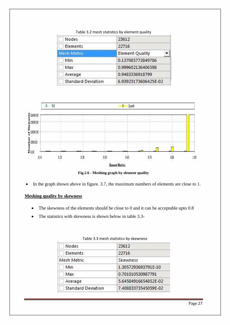
Table 3.2 mesh statistics by element quality
Fig.2.6 - Meshing graph by element quality
In the graph shown above in figure. 3.7, the maximum numbers of elements are close to 1.
Meshing quality by skewness
The skewness of the elements should be close to 0 and it can be acceptable upto 0.8
The statistics with skewness is shown below in table 3.3-
Table 3.3 mesh statistics by skewness

Page 28
Skewness by graph is shown below in figure 3.7
Fig.2.7 - Meshing graph by skewness
The yellow colour shows quadrilateral mesh where as light green shows triangular
mesh
Both the meshes are shown below-
Fig.2.8 – showing triangular and quadrilateral mesh
.
Quadrilateral
element
Triangular
element

Page 29
2.4 Solver setup and Solution-
After the meshing is completed the model is imported to FLUENT software and firstly the
mesh and mesh quality were checked and if the meshing is not good then error will be shown
and simulation will not be access further.
2.4.1 The governing equation-
The governing equation of computational fluid dynamics (CFD) is known as Navier-Stokes
equations. The Navier-Stokes equations consist of conservation of mass, momentum, energy,
species etc equations. The governing equations are following-
Conservation equation of mass
( )
Conservation equation of momentum
( )
Turbulent model equation-
The k- turbulent model is used for this experiment. Where k is the turbulent kinetic energy and
is turbulent dissipation energy, the governing equation for this are-
The turbulent kinetic energy k, is give by-
( )
( )
[(
)
]
Turbulent dissipation rate is given by

Page 30
( )
( )
[(
)
]
( )
Production of K- Represent the generation or production of turbulent kinetic energy due to mean
Velocity(m/s) gradient and is calculated by-
√( )
Modelling turbulent viscosity-
is the turbulent viscosity and is calculated as
The values of constant are
For the 2 phase flow VOF model is used and the governing equation for that is –
The tracking of the interfaces between the phases is accomplished by the solution of a
continuity equation for the volume fraction of one or more of the phases.
For the qth
phase, the governing equation is

Page 31
( ) ( ) ∑(
)
Where
Is the mass transfer from phase P to Q,
is the mass transfer from phase Q to P and
Is the source term
The equation will only be solved for more than one phase if only single phase is present then
governing equation is
∑
2.4.2 Setup data-
For simulation purpose, some date like fluid material, solver, turbulent model and boundary
Conditions, solution method, convergence criterion etc are assumed to be known. Table 3.3
Shows the input data according to problem and what we want in results.
Table 3.4 – Operating Parameter
Solver Pressure-based
Time Steady and transient
Turbulent model Standard turbulent k- model
Material Liquid steel
Operating pressure 101325 pa
Number of iteration-
Steady state- Till the convergence occur
Transient state 60 seconds

Page 32
2.5 Solution -
After applying the boundary condition the different cases are run in both the steady and
transient condition.
The different cases run are-
A. Single phase –
In single phase different cases run are -
1. Steady state tundish
2. Transient state tundish
3. Transient state tundish with dam and weir
4. Transient state tundish with curve dam and weir
5. Steady state tundish with mould
6. Transient state tundish with mould
7. Transient state tundish with mould and dam and weir
B. Two phase –
In multiphase only two cases are run which are as given below-
1. Two phase with tundish with dam and weir
2. Two phase with mould with dam and weir
C. DPM modal-
In DPM model a massless particle is injected through the surface of the inlet and particle
trajectory is seen and also the residence time is calculated for some cases
A. Single phase-
In single phase we have taken following boundary conditions-

Page 33
Table 3.5 – Material properties
Different profiles obtained in different cases are which were studied and discussed in
the result and discussion
Density 6800
viscosity 0.0059 ( )
Velocity(m/s) 1.69
For 2 phase
1st phase Slag
2nd
phase Liquid steel
Slag density 2500
Surface tension 0.4 N/

Page 34
Chapter - 3
Results
And
Discussions

Page 35
Part 3.1 – Only Tundish
Firstly only tundish without mold is run with and without the dam and weir and the different
profiles are obtained which are given below—
3.1.1 Steady state tundish
Firstly the model is simulated in steady state till the convergence of the
residuals.
The solution converged at 3000 iterations.
Velocity(m/s) and turbulent profiles are shown
Profiles at 1500 iterations and 3000 iterations are shown and compared
Velocity(m/s) profile-
(a)
(b)
Fig.3.1.1. – showing Velocity(m/s) profile in steady state (a) at 1500 and (b) at 3000 iterations

Page 36
Turbulent intensity profile-
(a)
(b)
Fig.3.1.2. – turbulent intensity profiles (a) at 1500 iterations and (b) at 3000 iterations
The Velocity(m/s) profile shows the flow motion of the liquid material with the slag and
turbulence intensity profiles shows the dissipation of turbulence in a model. Steady state cases
are run to check the stability of the solution and also the convergence of the solution

Page 37
3.1.2 Transient state tundish-
All the transient state cases have been run for 60 seconds with time step size is 0.01
Velocity(m/s) and the turbulent profiles have been shown at 30 sec and at 60 sec
Velocity(m/s) profile-
Velocity(m/s) profiles are shown below for 30 sec-
(a) (b)
(c)
Fig.3.1.3 –Velocity(m/s) profile at 30 sec (a) without dam and weir (b) with dam and weir (c) with curve
dam and weir
Velocity(m/s) profiles at 60 seconds are shown below -
(a) (b)
Fig.3.1.4– Velocity(m/s) profile at 60sec (a) without dam and weir (b) with rectangular dam and weir

Page 38
(a) (b)
Fig.3.1.5 – Velocity(m/s) profile at 60sec with rectangular dam and weir (b) with curve dam and weir
Velocity(m/s) profile shows the floatation of the liquid steel and the inclusion. From the
figure shown above it can be seen that flow control devices i.e. dam and weir deviate the
path of the flow and also it reduces the intensity of Velocity(m/s). Figure 3.2.3 (a) and (b)
compares the shape of dam i.e. a rectangular dam and a curve dam and it can be seen that
the rectangular dam provides the more inclination to the liquid steel than the curve dam
Turbulent intensity profile-
The turbulent profiles at 30 sec were shown
(a) (b)
(c)
Fig. 3.1.6 Showing turbulent intensity profile at 30 sec (a) without dam and weir (b) with dam and weir (c)
with curve dam and weir

Page 39
The turbulent profiles at 60 sec were shown below-
(a)
(b)
(c)
Fig.3.1.7 –Turbulent intensity profile at 60 sec (a) without dam and weir (b) with dam and weir (c) with
curve dam and weir
From the above figure it can be seen that dam and weir reduces the turbulence near the SEN
and it also prevents the SEN clogging and increases the SEN life.

Page 40
3.2 Tundish with mould
3.2.1 Steady state cases
Steady state tundish with mould is run and the solution converged at 90000 iterations.
Profiles shown are Velocity(m/s) and turbulent intensity
Profiles are shown at 45000 sec and 9000 sec
Velocity(m/s) profile-
a. At 45000 sec
(a)
(b)
Figure 3.2.1 Velocity(m/s) profiles (a) at 45000 sec and (b) at 90000 sec
Page 41
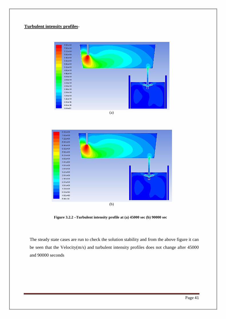
Turbulent intensity profiles-
(a)
(b)
Figure 3.2.2 –Turbulent intensity profile at (a) 45000 sec (b) 90000 sec
The steady state cases are run to check the solution stability and from the above figure it can
be seen that the Velocity(m/s) and turbulent intensity profiles does not change after 45000
and 90000 seconds

Page 42
3.2.2 Transient state –
Transient case are run for 1 min with and without dam and weir
Velocity(m/s) and turbulent intensity profiles at 30sec and 90sec are shown and
compare.
Velocity(m/s) profiles
(a)
(b)

Page 43
(c)
(d)
Figure 3.2.3 -Velocity(m/s) profiles without dam and weir (a) at 30 sec (b) at 60 sec (c) and with dam and
weir (a) at 30 sec (b) at 60 sec
From the figure shown above it can be seen that the dam and weir does not effect the
Velocity(m/s) of the liquid material they only deviate the Velocity(m/s) i.e. they changes the
path of the Velocity(m/s) as it can be seen that Velocity(m/s) in the nozzle is same with and
without dam and weir, so dam and weir provides floatation to the liquid steel.
Turbulent intensity profile
(a)

Page 44
(b)
(b)
(d)
Figure 3.2.4 –turbulent intensity profiles without dam and weir (a) at 30 sec (b) at 60 sec (c) and with dam
and weir (a) at 30 sec (b) at 60 sec

Page 45
The dam and weir reduces the turbulent intensity near the SEN area which can been seen from
the above figure
3.3 Two Phase-
A 2D two phase with tundish including mould, dam and weir is run as slag being the 1st phase
and liquid steel being the 2nd
phase in transient case. The result shown below
Slag profile
(a)
(b)

Page 46
Figure 3.3.1- Shows the slag profile of the two phases (a) 30 sec and (b) 60 sec
Liquid steel
(a)
(b)
Figure 3.3.2- Shows the liquid steel profile of the two phases (a) 30 sec and (b) 60 sec
From the above figure it can be seen that the slag is entering in the mould region and from the
literature review study (10-15) % inclusion can be removed from the mould by using the
casting powder which is sprayed on the mold which attracts the slag which can be seen from
the figure.

Page 47
3.4. DPM MODAL-
DPM stands for discrete phase modeling which tracks the motion of individual (discrete)
particles.
Some principles are applied whether a particle is a solid particle or liquid particles
Trajectory of each particle(droplet) is computed over a large number of steps
A massless particle is injected from the surface of the inlet and the trajectory and the
residence time is calculated on the same basis.
1. Different Cases run with DPM modal are –
A. Single phase
1. Only tundish
a. Steady state tundish
b. Transient state tundish
c. Transient case tundish with dam and weir
2. Tundish with mold
a. Steady state tundish with mould
b. Transient case tundish with mould
c. Transient case tundish with dam and weir and with mould
B. Two phase
a. Transient case tundish and mould, dam and weir

Page 48
3.4.1 Single phase
A. Only tundish
(a) (b)
Figure 3.4.1 – particle tracking without dam and weir (a) at 1500 sec (b) at 3000 sec in steady state
(a) (b)
Figure 3.4.2 – particle tracking without dam and weir (a) at 30 sec (b) at 60 sec in transient state
(a) (b)
Figure 3.4.3 – particle tracking with dam and weir (a) at 30 sec (b) at 60 sec in transient state

Page 49
B. Tundish with mold
(a) (b)
Figure 3.4.4 – particle tracking without dam and weir (a) at 30 sec (b) at 60 sec in transient state
(a) (b)
Figure 3.4.5 – particle tracking with dam and weir (a) at 30 sec (b) at 60 sec in transient state
From the particle trajectory it can be seen that the recirculation zone is less with dam and weir
then without dam and weir and also the dam and weir provides enough time for the bubble
particle to float and can be extracted by the slag

Page 50
3.4.2 Two phase
a. Transient case tundish with mould dam and weir
(a) (b)
Fig.3.4.6- particle tracking of the hot metal (a) at 30sec and (b) at 60 sec
(a) (b)
Fig.3.4.7- particle tracking of the slag metal (a) at 30sec and (b) at 60 sec

Page 51
3.5 Residence time
Residence time is the time taken by the liquid metal to flow from tundish to mold. If the
residence time is less then inclusion will not have the enough time to float and they can
be trapped and can go into the mold which detroits the properties of the solidified. A
massless particle is injected from the inlet of the tundish and the residence time is
calculated only for the tundish which is shown in the table 3.7 below.
Table3.6- calculated residence time
Cases Time
Without dam and weir 31 sec
With curve dam and weir 68 sec
With rectangular dam and weir 120 sec
So from the residence time calculated it can be said that the flow control devices increases the
residence time so the inclusion can float and can come up on the surface of the tundish where
they can be taken out from the slag.
Page 52
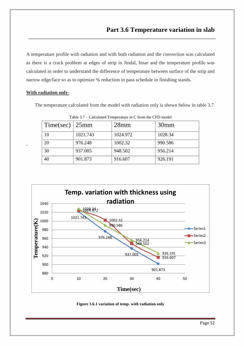
Part 3.6 Temperature variation in slab
A temperature profile with radiation and with both radiation and the convection was calculated
as there is a crack problem at edges of strip in Jindal, hisar and the temperature profile was
calculated in order to understand the difference of temperature between surface of the strip and
narrow edge/face so as to optimize % reduction in pass schedule in finishing stands.
With radiation only-
The temperature calculated from the model with radiation only is shown below in table 3.7
Table 3.7 – Calculated Temperature in C from the CFD model
.
Figure 3.6.1 variation of temp. with radiation only
1021.743
976.248
937.005
901.873
1024.972
1002.32
948.502
916.607
1028.34
990.586
956.214
926.191
880
900
920
940
960
980
1000
1020
1040
0 10 20 30 40 50
Tem
per
atu
re(K
)
Time(sec)
Temp. variation with thickness using radiation
Series1
Series2
Series3
Time(sec) 25mm 28mm 30mm
10 1021.743 1024.972 1028.34
20 976.248 1002.32 990.586
30 937.005 948.502 956.214
40 901.873 916.607 926.191

Page 53
With radiation and convection only-
The temperature calculated from the model with radiation and convection is shown below in
table 3.8
Table 3.8 – Calculated Temperature in C from the CFD model
Figure 3.6.2 variation of temperature with radiation and convection
From the model using radiation and with radiation and convection both, the temperatures
were calculated from the temperature profiles and with the increase in strip thickness the
temperature decreases so on the basis of this and the calculated temperature the strip thickness
is optimized and it shows that the cracks are reduced by 25% as previously, cracks was 100
1004.995
945.698
894.6155
849.848
1009.1515
956.948
910.948
868.835
1013.57
963.145
918.7735
880.1925
840
860
880
900
920
940
960
980
1000
1020
1040
0 10 20 30 40 50
Tem
per
atu
re(C
)
Time(sec)
Temp. variation with thickness using radiation and convection
Series1
Series2
Series3
Time(sec) 25mm 28mm 30mm
10 1004.995 1009.152 1013.57
20 945.698 956.948 963.145
30 894.6155 910.948 918.7735
40 849.848 868.835 880.1925

Page 54
mm (total 200 mm) both side of the strip. After modification of percentage reduction the edge
cracks reduces to ~25 mm both side (Total 50 mm). This was done in 2 coils.
Page 55
Chapter- 4
Conclusion

Page 56
4. Conclusion
A computational fluid dynamic (CFD) study is conceded on the continuous casting process to
achieve the desired objective. A Standard turbulent k- model is used for the CFD analysis. In
this simulation, a tundish with and without the rectangular and a curve dam and weir are used
for the simulation and on the basis of calculated residence time from the DPM model by
injecting a massless particle it was concluded that the rectangular Dam and Weir is the most
effective in reducing the turbulence at the SEN side. A two phase model is also studied and the
slag profile is shown in the result and discussion which shows the use of casting powder in the
mold. The strip temperature is calculated using the radiation first and in the second both
radiation and convection as the training project in the Jindal and on the basis of the results the
strip thickness is modified which shows that there is 25 percent reduction in the crack, so on
this basis it can be said that mathematical model is very good at predicting flow behavior and
the temperature profile and consequently the crack generation possibility in casted slab and can
be applied to industries.

Page 57
Chapter- 5
References

Page 58
REFRENCES-
Arakawa, K., Kawai, K., Katahashi, S., Taniguchi, K., Mori, H., & Ayata, K. (1996).
Development of large sized semi-continuous casting process. ISIJ international 36(Suppl),
S204-S207.
Bellet, M & Heinrich A, (2004). A two-dimensional finite element thermo mechanical
approach to a global stress-strain analysis of steel continuous casting. Isij
International, 44(10), pages-1686
Bessho, N., Yamasaki, H., Fujii, T., Nozaki, T., & Hiwasa, S. (1992). Removal of inclusion
from molten steel in continuous casting tundish. ISIJ international,32(1), 157-163.
Blazek, K. E., & Kelly, J. E. (1997). The improvement of surface quality of continuous
rheocast bars of steel and high melting point alloys. ISIJ international, 37(4), 365-374.
Braun, A., Warzecha, M., & Pfeifer, H. (2010). Numerical and physical modeling of steel
flow in a two-strand tundish for different casting conditions .Metallurgical and Materials
Transactions B, 41(3), 549-559.
Chaudhary, R., Lee, G. G., Thomas, B. G., Cho, S. M., Kim, S. H., & Kwon, O. D. (2011).
Effect of Stopper-Rod Misalignment on Fluid Flow in Continuous Casting of
Steel. Metallurgical and Materials Transactions B, 42(2), 300-315.
Chaudhary, R., Lee, G. G., Thomas, B. G., & Kim, S. H. (2008). Transient mold fluid flow
with well-and mountain-bottom nozzles in continuous casting of steel. Metallurgical and
Materials Transactions B, 39(6), 870-884.
Damle, C., & Sahai, Y. (1996). A criterion for water modeling of non-isothermal melt flows
in continuous casting tundishes. ISIJ international, 36(6), 681-689.

Page 59
Ding, N., Bao, Y. P., Sun, Q. S., & Wang, L. F. (2011). Optimization of flow control devices
in a single-strand slab continuous casting tundish. International Journal of Minerals,
Metallurgy, and Materials, 18(3), 292-296.
He, Z., Zhou, K., Liu, S., Xiong, W., & Li, B. (2013, November). Numerical Modeling of
the Fluid Flow in Continuous Casting Tundish with Different Control Devices. In Abstract
and Applied Analysis (Vol. 2013). Hindawi Publishing Corporation
Hibbeler, L. C., & Thomas, B. G. (2010, May). Investigation of Mold Flux Entrainment in
CC Molds Due to Shear Layer Instability. In AISTech 2010 Steelmaking Conference Proc.
Ho, Y. H., Chen, C. H., & Hwang, W. S. (1994). Analysis of molten steel flow in slab
continuous caster mold. ISIJ international, 34(3), 255-264
Ho, Y. H., & Hwang, W. S. (1996). The analysis of molten steel flow in billet continuous
casting mold. ISIJ international, 36(8), 1030-1035.
Huang, X., & Thomas, B. G. (1996). Intermixing model of continuous casting during a
grade transition. Metallurgical and Materials Transactions B, 27(4), 617-632.
Huang, X., & Thomas, B. G. (1998). Modeling of transient flow phenomena in continuous
casting of steel. Canadian Metallurgical Quarterly, 37(3-4), 197-212.
Kiyose, A., Miyazawa, K. I., Yamada, W., Watanabe, K., & Takahashi, H. (1996).
Mathematical modelling of change in composition of mold flux in continuous casting of
steels. ISIJ international, 36(Suppl), S155-S158.
Ludwig, A., Kharicha, A., & Wu, M. (2014). Modeling of Multiscale and Multiphase
Phenomena in Materials Processing. Metallurgical and Materials Transactions B, 45(1), 36-
43.
Mazumdar, D., & Guthrie, R. I. (1999). The physical and mathematical modelling of
continuous casting tundish systems. ISIJ international, 39(6), 524-547.

Page 60
Mishra, P., Ajmani, S. K., Kumar, A., & Shrivastava, K. K. (2012). NUMERICAL
MODELLING OF SEN AND MOULD FOR CONTINUOUS SLAB CASTING.
Moon, K. H., Shin, H. K., Kim, B. J., Chung, J. Y., Hwang, Y. S., & Yoon, J. K. (1996).
Flow control of molten steel by electromagnetic brake in the continuous casting mold. ISIJ
international, 36(Suppl), S201-S203.
Ogibayashi, S., Yamada, M., Yoshida, Y., & Mukai, T. (1991). Influence of Roll Bending
on Center Segregation in Continuously Cast Slabs. ISIJ international,31(12), 1408-1415
Santis, M. D., & Ferretti, A. (1996). Thermo-fluid-dynamics modelling of the solidification
process and behaviour of non-metallic inclusions in the continuous casting slabs. ISIJ
International, 36(6), 673-680.
Sengupta, J., Thomas, B. G., Shin, H. J., Lee, G. G., & Kim, S. H. (2006). A new
mechanism of hook formation during continuous casting of ultra-low-carbon steel
slabs. Metallurgical and materials transactions A, 37(5), 1597-1611
Tanikawa, K., Ishiguro, S., & Matsuo, K. (1996). Improvement of Steel Quality by
Advanced Tundish Technology in New Slab Caster at Kakogawa Works, Kobe Steel,
Ltd. ISIJ international, 36(Suppl), S81-S84.
Tanaka, T., Kuroda, A., & Kurita, K. (1992). Continuous casting of titanium alloy by an
induction cold crucible. ISIJ international, 32(5), 575-582.
Tanaka, H., Tsujino, R., Imamura, A., Nishihara, R., & Konishi, J. (1994). Effect of length
of vertical section on inclusion removal in vertical bending-type continuous casting
machine. ISIJ international, 34(6), 498-506.
Tsutsumi, K., Nagasaka, T., & Hino, M. (1999). Surface roughness of solidified mold flux
in continuous casting process. ISIJ international, 39(11), 1150-1159.

Page 61
Thomas, B. G., Yuan, Q., Zhang, L., & Vanka, S. P. (2004). Flow Dynamics and Inclusion
Transport in Continuous Casting of Steel. In Proceedings of NSF Conference on Design,
Service, and Manufacturing Grantees and Research, Birmingham (pp. 2328-2362)
Thomas, B. G., Yuan, Q., Mahmood, S., Liu, R., & Chaudhary, R. (2014). Transport and
Entrapment of Particles in Steel Continuous Casting.Metallurgical and Materials
Transactions B, 45(1), 22-35.
Thomas, B. G., Yuan, Q., Sivaramakrishnan, S., & Vanka, S. P. (2002). Transient fluid flow
in a continuous steel-slab casting mold. J. Metals: JOM-e, http://www. tms.
org/pubs/journals/JOM/0201/Thomas/Thomas-0201. html.
Thomas, B. G., Koric, S., Hibbeler, L. C., & Liu, R. (2011). Multiphysics Model of
Continuous Casting of Steel Beam-Blanks. In Proceedings of the 4th International
Conference on Modeling and Simulation of Metallurgical Processes in Steelmaking.
Thomas, B. G., Yuan, Q., Sivaramakrishnan, S., Shi, T., Vanka, S. P., & Assar, M. B.
(2001). Comparison of four methods to evaluate fluid velocities in a continuous slab casting
mold. ISIJ international, 41(10), 1262-1271.
Thomas, B. G. (2006). Modeling of continuous casting defects related to mold fluid
flow. Iron and Steel Technology, 3(7), 127.
Thomas, B. G., & Vanka, S.P.. (2002 Flow Dynamics and Inclusion Transport in
Continuous Casting of Steel. NSF Design, Service, Manufacturing and Industrial Innovation
Research Conf., San Juan, Puerto Rico, January 7-10,
Thomas, B. G., & Zhang, L. (2001). Mathematical modeling of fluid flow in continuous
casting. ISIJ international, 41(10), 1181-1193.
Thomas, B. G. (2002). Modeling of the continuous casting of steel—past, present, and
future. metallurgical and materials transactions B, 33(6), 795-812.
.
Page 62
Thomas, B. G. (1995). Issues in thermal-mechanical modeling of casting processes. ISIJ
international, 35(6), 737-743.
Thomas, B. G. (2003). Modeling of Continuous casting. The Making, Shaping and Treating
of Steel, 11th ed., Casting Volume, The AISE Steel Foundation, Pitsburg.
Thomas, B. G., Denissov, A., & Bai, H. (1997, April). Behavior of argon bubbles during
continuous casting of steel. In Steelmaking Conference Proceedings (Vol. 80, pp. 375-384).
IRON AND STEEL SOCIETY OF AIME.
Thomas, B. G., & Najjar, F. M. (1991). Finite element modelling of turbulent fluid flow and
heat transfer in continuous casting. Applied Mathematical Modelling, 15(5), 226-243.
Wen, G. H., Huang, Y. F., Tang, P., & Zhu, M. M. (2012). Improvement of tundish shape
and optimization of flow control devices for sequence casting heavy steel
ingots. International Journal of Minerals, Metallurgy, and Materials,19(1), 15-20.
Won, Y. M., Yeo, T. J., Oh, K. H., Park, J. K., Choi, J., & Yim, C. H. (1998). Analysis of
mold wear during continuous casting of slab. ISIJ international,38(1), 53-62.
Yamauchi, A., Sorimachi, K., Sakuraya, T., & Fujii, T. (1993). Heat transfer between mold
and strand through mold flux film in continuous casting of steel.ISIJ international, 33(1),
140-147.
Yang, H., Zhang, X., Deng, K., Li, W., Gan, Y., & Zhao, L. (1998). Mathematical
simulation on coupled flow, heat, and solute transport in slab continuous casting
process. Metallurgical and materials transactions B, 29(6), 1345-1356.
Zhang, L., Aoki, J., & Thomas, B. G. (2006). Inclusion removal by bubble flotation in a
continuous casting mold. Metallurgical and materials transactions b, 37(3), 361-379.
Zhao, B., Thomas, B. G., Vanka, S. P., & O’malley, R. J. (2005). Transient fluid flow and
superheat transport in continuous casting of steel slabs.Metallurgical and Materials
Transactions B, 36(6), 801-823.

Page 63
Zhao, B., Vanka, S. P., & Thomas, B. G. (2005). Numerical study of flow and heat transfer
in a molten flux layer. International journal of heat and fluid flow,26(1), 105-118.
Zhang, L., & Thomas, B. G. (2005, June). Application of Computational Fluid Dynamics to
Steel Refining and Casting Processes. In Fourth International Conference on CFD in Oil
and Gas, Metallurgical and Process Industries SINTEF, NTNU, Trondheim, Norway.
Zhang, L., Aoki, J., Thomas, B. G., Peter, J., & Peaslee, K. D. (2005, May). Designing a
new scrap-based continuous steelmaking process using CFD simulation. In ICS 2005-The
3rd International Congress on the Science and Technology of Steelmaking.
.

Page 64