cs183 tutorial sequence state diagrams
TRANSCRIPT

Tutorial for iUMLite Creation of Sequence Diagrams and State Machine Diagrams
Useful Links: http://www.kc.com You can download an evaluation version of the software from here, including manuals. On the lab machines, the iUMLite tutorial is available in:

INSTRUCTIONS FOR USING iUMLite Create a new folder in your home directory (H:) and name it Lab_3_Seq _Sta From the Start Menu select:
- All Programs - Departmental Software
- Computing - iUMLite
- Modeller Lite

1. Create an iUMLite Database
iUMLite saves the information you enter in a database. This database is a set of folders and files that are stored in the directory that you specify. To do this:
a. Select File – New Repository… (Screenshot 1)
Screenshot 1
b. Navigate to the area you wish to save the database. (I suggest to use the new folder you created in your home directory). (Screenshot 2)
Screenshot 2

c. Enter a name for the database, for example, Seq_Sta and click OK. (Screenshot
3)
Screenshot 3
d. Enter the following fields (for example, your name, in the administrator field, and type the word unis in the database field) in your database and click OK. (Screenshot 4)
Screenshot 4

You have now created a database in your home directory.
e. The following window will appear (Screenshot 5)
Screenshot 5
2. Create a Project
f. - Right click on Projects → Acquire Lock → Top Level (Screenshot 6)
Screenshot 6

g. Right click on Projects → Add Project → Select <New> (Screenshot 7)
Screenshot 7
h. The following window will appear (Screenshot 8)
Screenshot 8

- Fill in the details of the project and click OK. - Enter Exercise in the Name field, and enter any letter (for example E)
in the Key Letter field. (Screenshot 9)
Screenshot 9 Leave the Build Area field blank for now. So far you've learned how to create a project using iUMLite. Next you will learn how to create a sequence diagram.

3. Create a Sequence Diagram
Typically a Sequence Diagram captures the parts of the system that correspond to a single Use Case. In this tutorial consider the Use Case that is described in your lab sheet.
3.1 Create a Use Case
i. Expand the tree to Project → Exercise → Initial Version → Use Case Model (Screenshot 10)
Screenshot 10
j. Right click on Use Cases select Add Use Case (Screenshot 11)
Screenshot 11

The following screenshot will appear (Screenshot 12)
Screenshot 12 Give any name you like in the Name field (example Video) and select OK. Now you have created your Use Case Description. The next step is to create your Sequence Diagram. So, expand the tree to Use Cases → Video → Sequence Diagrams (Screenshot 13)
Screenshot 13 Right click on Video select Show Sequence Diagram (Screenshot 14)
Screenshot 14

The following screenshot will appear. (Screenshot 15)
Screenshot 15 On the right hand side of the screen the Sequence Diagram, which is initially blank, will appear.

On the Sequence Diagram, the outside world (including the actors) is represented by a thick vertical bar on the left hand side of the diagram, which is called the System Boundary. Add a lifeline Right click on canvas Add select Lifeline. (Screenshot 16)
Screenshot 16 The following screenshot will appear (Screenshot 17)
Screenshot 17

Select <New Domain>. The following screenshot will appear. (Screenshot 18)
Screenshot 18 Give any name you like in the Name field (for example Customerdatabase) and select OK. Add an Interaction (Messages) Right click on the lifeline • Add • Interaction (Screenshot 19)
Screenshot 19
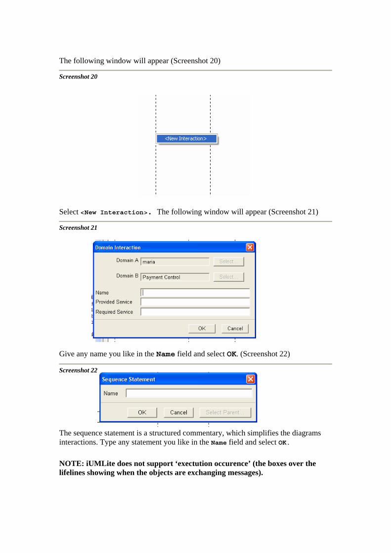
The following window will appear (Screenshot 20)
Screenshot 20 Select <New Interaction>. The following window will appear (Screenshot 21)
Screenshot 21 Give any name you like in the Name field and select OK. (Screenshot 22)
Screenshot 22 The sequence statement is a structured commentary, which simplifies the diagrams interactions. Type any statement you like in the Name field and select OK. NOTE: iUMLite does not support ‘exectution occurence’ (the boxes over the lifelines showing when the objects are exchanging messages).
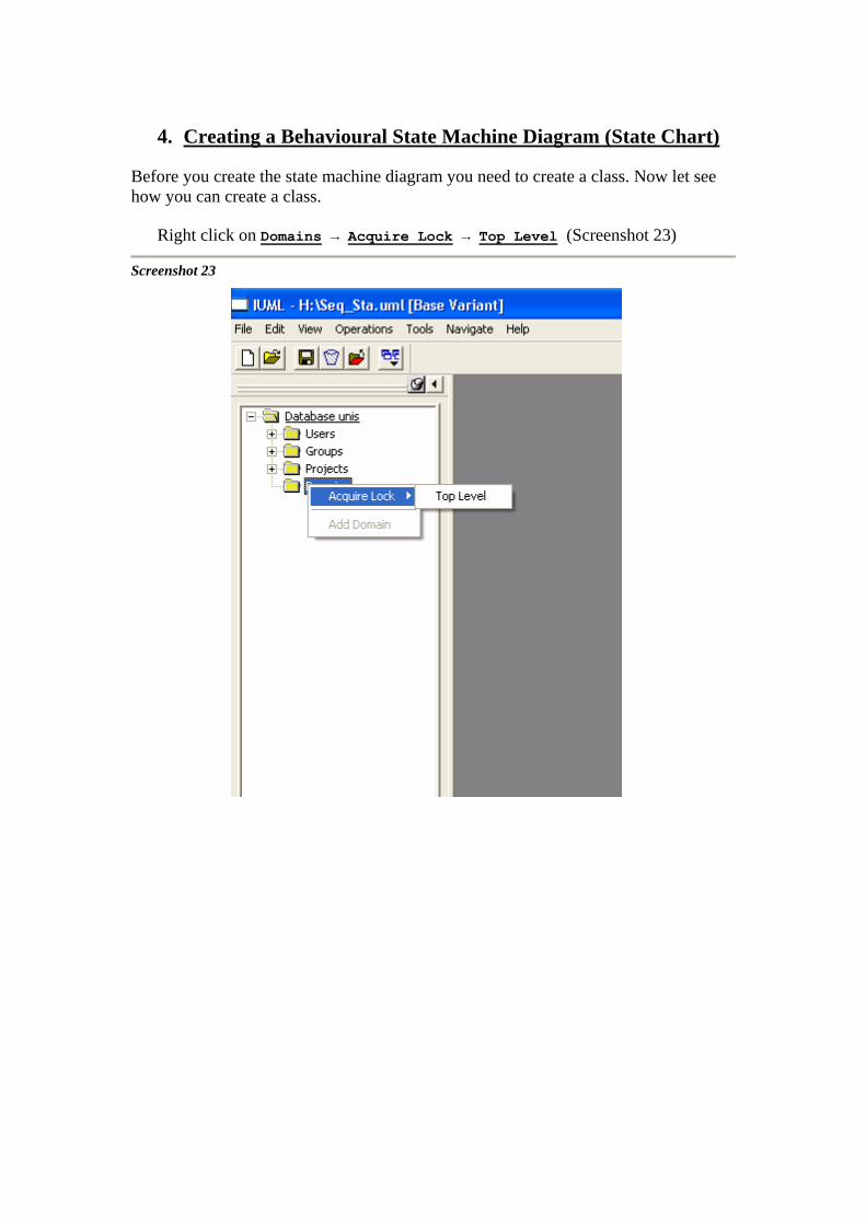
4. Creating a Behavioural State Machine Diagram (State Chart)
Before you create the state machine diagram you need to create a class. Now let see how you can create a class.
Right click on Domains → Acquire Lock → Top Level (Screenshot 23)
Screenshot 23

Right click on Domains → Add Domain → <New> (Screenshot 24)
Screenshot 24
The following screenshot will appear (Screenshot 25)
Screenshot 25

• Enter the following fields (for example, VideoClass, in the name field and any letter in the Key Letter field.
• Select OK.
Expand the tree to Domains → VideoClass (Screenshot 26)
Screenshot 26
Right click on Initial Version and select Show Class Diagram (Screenshot 27)
Screenshot 27

The following screenshot will appear (Screenshot 28)
Screenshot 28
Right click on the canvas → Add → Class. (Screenshot 29)
Screenshot 29

The following screenshot will appear (Screenshot 30)
Screenshot 30
Give any name you like in the Name field (example Video) and select OK.
The following screenshot will appear (Screenshot 31)
Screenshot 31

Now that you create a class let's see how you can create a state machine diagram for this class.
Right click on the class → Modify → Create State Machine. (Screenshot 32)
Screenshot 32
The following screenshot will appear (Screenshot 33)
Screenshot 33
Select Yes.

Right click on the class and select Show State Chart. (Screenshot 34)
Screenshot 34

Add a state
Right click on the canvas → Add → State. (Screenshot 35)
Screenshot 35
The following screenshot will appear. (Screenshot 36)
Screenshot 36 Give any name you like in the Name field and select OK.

Add a Transition, Creation Transition (Initial State), Deletion Transition (Final State)
Right click on the class → Add → Transition or Creation Transition or Deletion. (Screenshot 37)
Screenshot 37 Note: you should use a text annotation to add an event for a Transition.