sequence & statechart diagrams month day, year. agenda training plan overview actors and use...
TRANSCRIPT
Sequence & Statechart Diagrams
Month Day, Year
AgendaTraining Plan OverviewActors and Use Case DiagramsSequence Diagrams
Diagram ElementsEvolution in the Models
Statechart DiagramsState MachinesStates
ExerciseNext Steps
Training Plan OverviewIntroductionUsing Rational AdministratorUsing ClearCaseUsing ClearQuestUsing Rational Rose XDEIdentifying & Creating Use-Cases – Part 1Identifying & Creating Use-Cases – Part 2Detailing Requirements withRequisiteProActors and Use-Case DiagramsSequence and Statechart DiagramsCollaboration and Class DiagramsIntegration and Development with the .NET Framework
Review - Actors & EntitiesBusiness Actor
Represents a role played in relation to the business by someone or something in the business environment
Business WorkerRepresents an abstraction of a human that interacts within the systemActive
Business EntityRepresent an object that business workers access, inspect, manipulate, produce, …Provide the basis for sharing Passive
ActorRepresents someone in a role who interacts with the systemInteracts with but have no control over use-cases
EntityRepresents an object used to model information and associated behaviorMay be persistentMay be active or passive
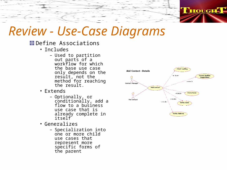
Review - Use-Case DiagramsDefine Associations
• Includes– Used to partition out
parts of a workflow for which the base use case only depends on the result, not the method for reaching the result.
• Extends– Optionally, or
conditionally, add a flow to a business use case that is already complete in itself
• Generalizes– Specialization into
one or more child use cases that represent more specific forms of the parent
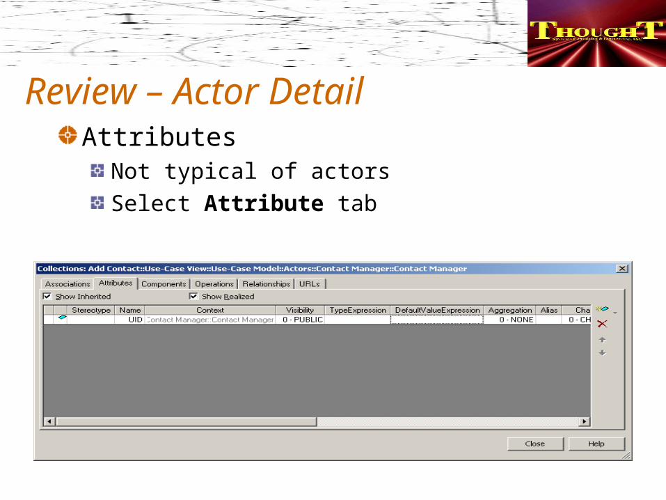
Review – Actor DetailAttributes
Not typical of actorsSelect Attribute tab
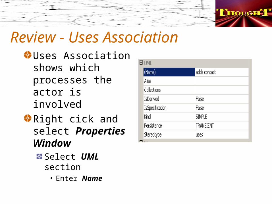
Review - Uses AssociationUses Association shows which processes the actor is involved Right cick and select Properties Window
Select UML section
• Enter Name
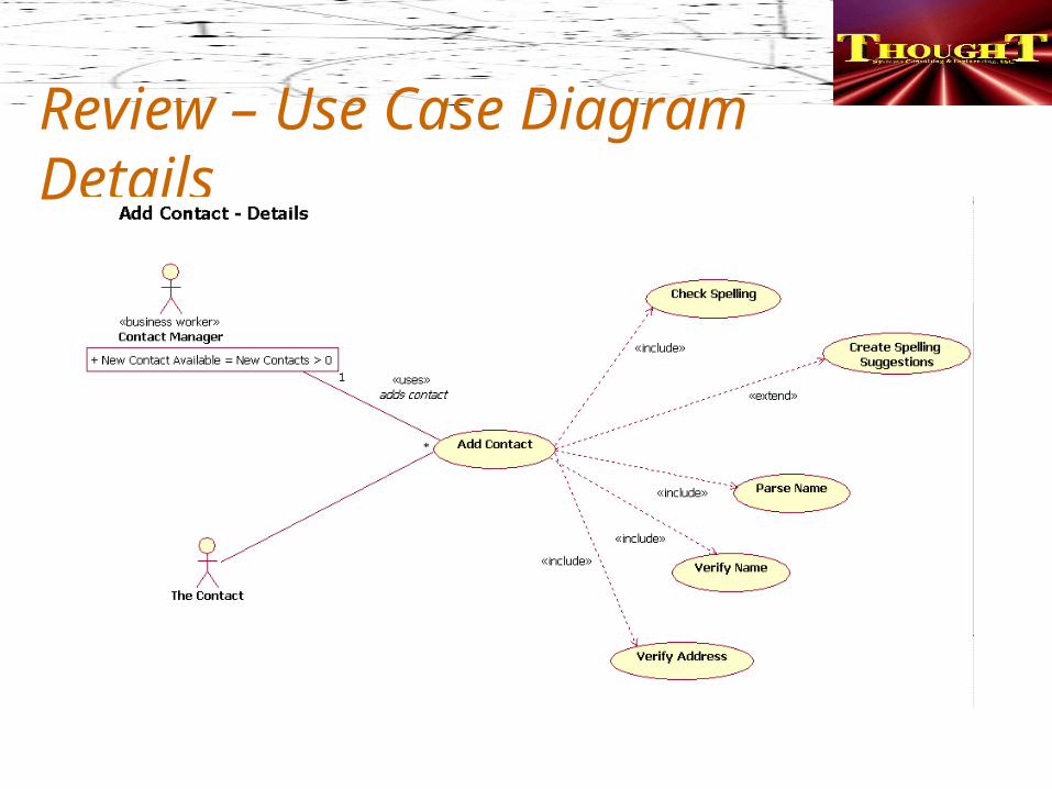
Review – Use Case Diagram Details
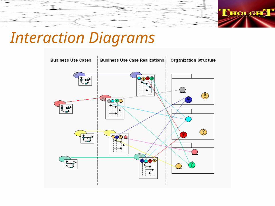
Interaction Diagrams
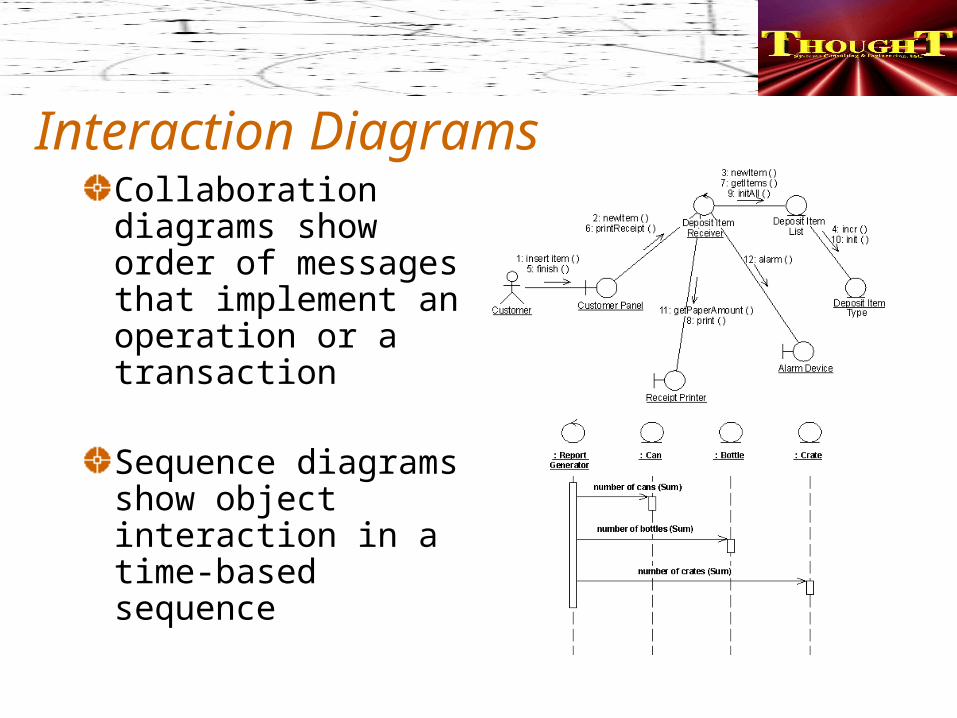
Interaction DiagramsCollaboration diagrams show order of messages that implement an operation or a transaction
Sequence diagrams show object interaction in a time-based sequence
Sequence Diagrams - OverviewUses
Show object interaction in a time-based sequenceEstablish the roles of objects Provide essential information to determine class responsibilities and interfaces
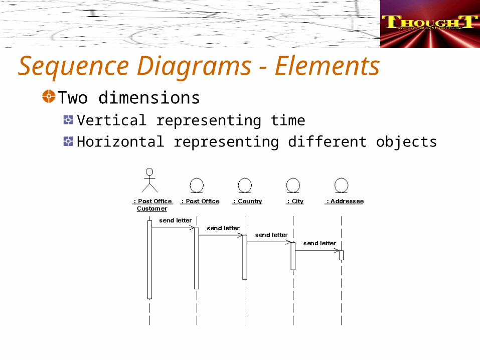
Sequence Diagrams - ElementsTwo dimensions
Vertical representing time Horizontal representing different objects
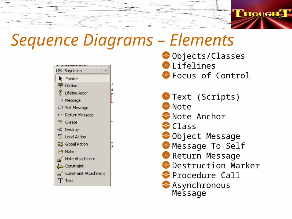
Sequence Diagrams – ElementsObjects/ClassesLifelinesFocus of Control
Text (Scripts)NoteNote AnchorClassObject MessageMessage To SelfReturn MessageDestruction MarkerProcedure CallAsynchronous Message
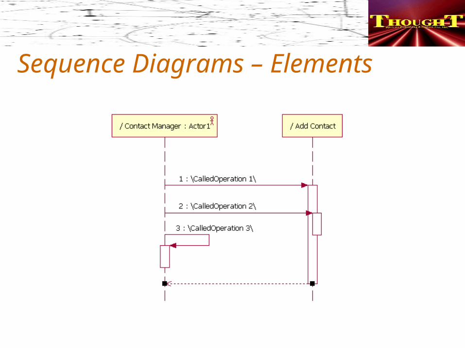
Sequence Diagrams – Elements
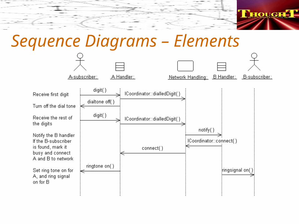
Sequence Diagrams – Elements
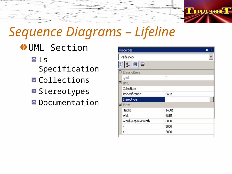
Sequence Diagrams – LifelineUML Section
Is SpecificationCollectionsStereotypesDocumentation
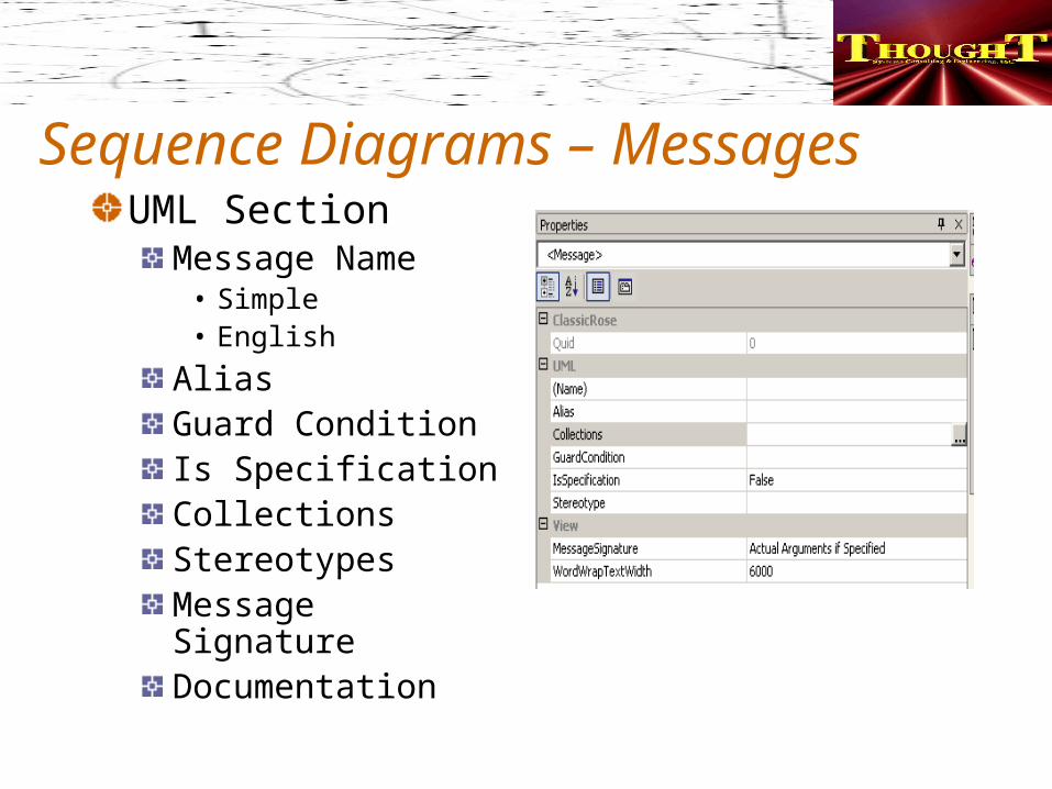
Sequence Diagrams – MessagesUML Section
Message Name• Simple• English
AliasGuard ConditionIs SpecificationCollectionsStereotypesMessage SignatureDocumentation
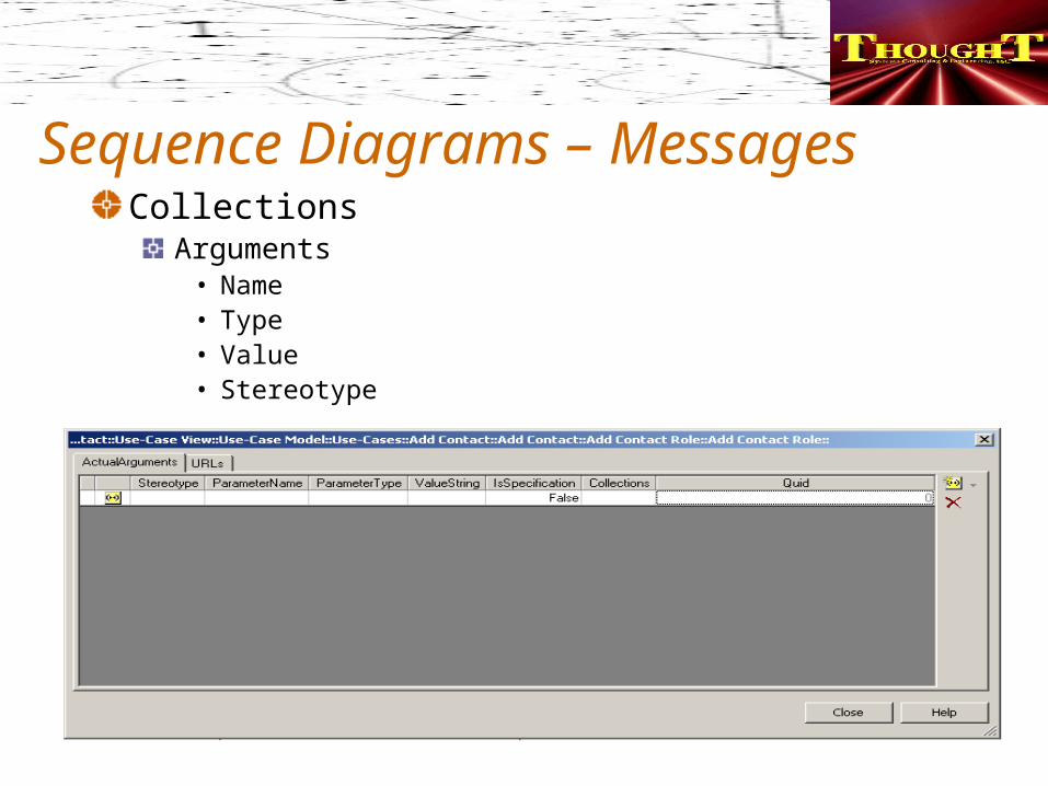
Sequence Diagrams – MessagesCollections
Arguments• Name• Type• Value• Stereotype
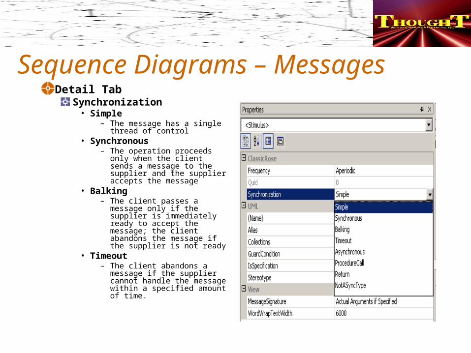
Sequence Diagrams – MessagesDetail Tab
Synchronization• Simple
– The message has a single thread of control
• Synchronous– The operation proceeds
only when the client sends a message to the supplier and the supplier accepts the message
• Balking– The client passes a
message only if the supplier is immediately ready to accept the message; the client abandons the message if the supplier is not ready
• Timeout– The client abandons a
message if the supplier cannot handle the message within a specified amount of time.
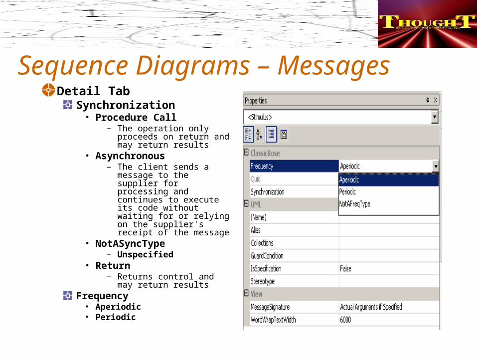
Sequence Diagrams – MessagesDetail Tab
Synchronization• Procedure Call
– The operation only proceeds on return and may return results
• Asynchronous– The client sends a
message to the supplier for processing and continues to execute its code without waiting for or relying on the supplier's receipt of the message
• NotASyncType– Unspecified
• Return– Returns control and
may return resultsFrequency
• Aperiodic• Periodic
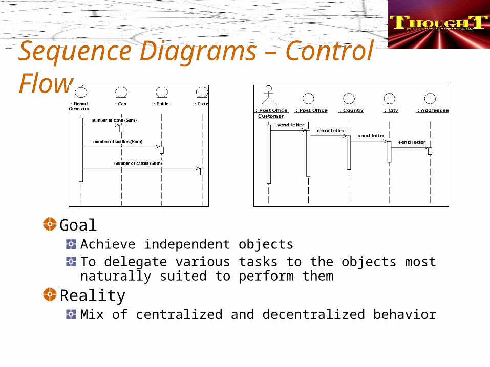
Sequence Diagrams – Control Flow
GoalAchieve independent objectsTo delegate various tasks to the objects most naturally suited to perform them
RealityMix of centralized and decentralized behavior
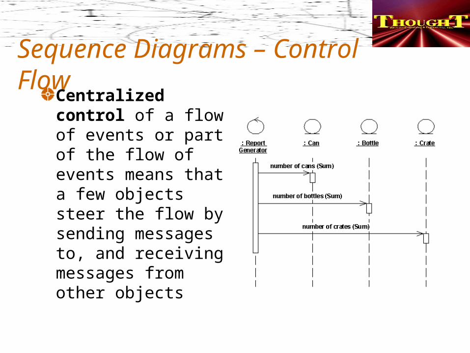
Sequence Diagrams – Control FlowCentralized control of a flow of events or part of the flow of events means that a few objects steer the flow by sending messages to, and receiving messages from other objects
Sequence Diagrams – Control FlowCentralized control
Use• If the order in which the sub-event phases will be
performed is likely to change• To insert new sub-event phases• To keep parts of the functionality reusable as
separate pieces
To recognize look for fork-shaped structure
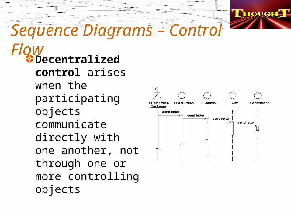
Sequence Diagrams – Control FlowDecentralized control arises when the participating objects communicate directly with one another, not through one or more controlling objects
Sequence Diagrams – Control FlowDecentralized control
Use• If sub-event phases are tightly coupled• If forming a part-of or consists-of hierarchy• To form a conceptual inheritance hierarchy• To represent a fixed chronological progression• To encapsulate and thereby make abstractions of
functionality
To recognize look for stairway-shaped structure
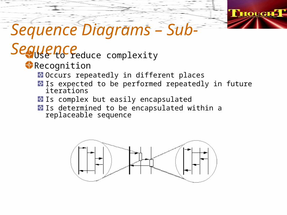
Sequence Diagrams – Sub-SequenceUse to reduce complexityRecognition
Occurs repeatedly in different placesIs expected to be performed repeatedly in future iterationsIs complex but easily encapsulatedIs determined to be encapsulated within a replaceable sequence
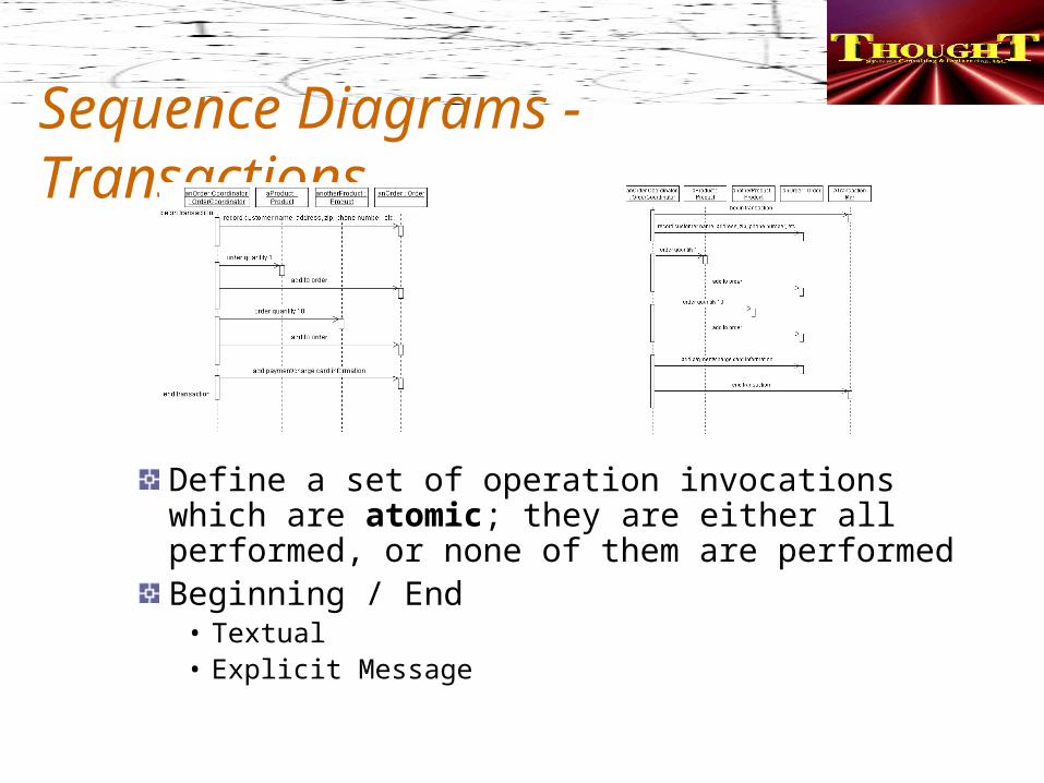
Sequence Diagrams - Transactions
Define a set of operation invocations which are atomic; they are either all performed, or none of them are performedBeginning / End
• Textual• Explicit Message
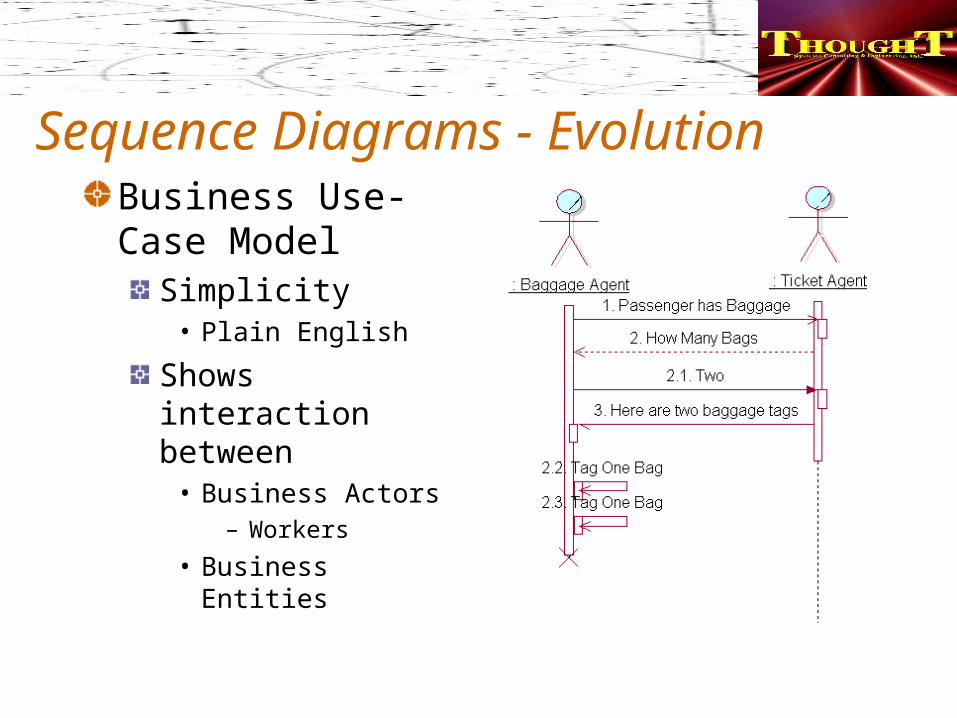
Sequence Diagrams - EvolutionBusiness Use-Case Model
Simplicity• Plain English
Shows interaction between
• Business Actors– Workers
• Business Entities
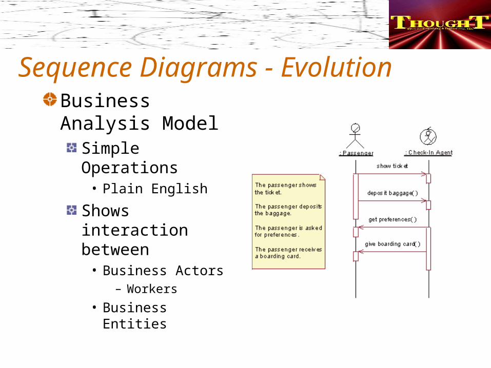
Sequence Diagrams - EvolutionBusiness Analysis Model
Simple Operations• Plain English
Shows interaction between
• Business Actors– Workers
• Business Entities
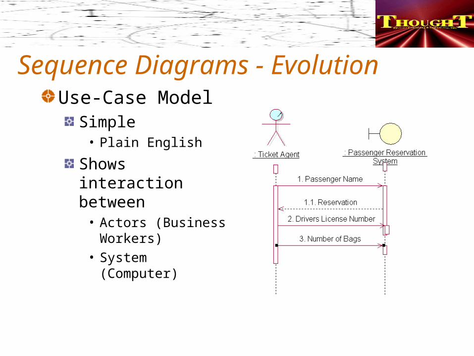
Sequence Diagrams - EvolutionUse-Case Model
Simple• Plain English
Shows interaction between
• Actors (Business Workers)
• System (Computer)
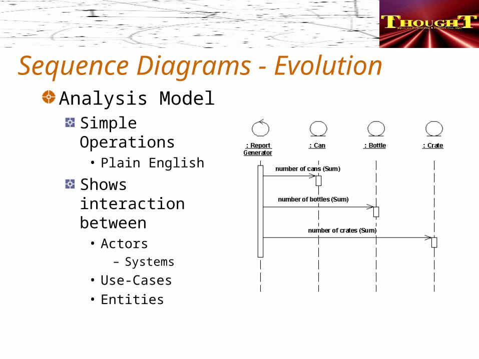
Sequence Diagrams - EvolutionAnalysis Model
Simple Operations• Plain English
Shows interaction between
• Actors– Systems
• Use-Cases• Entities
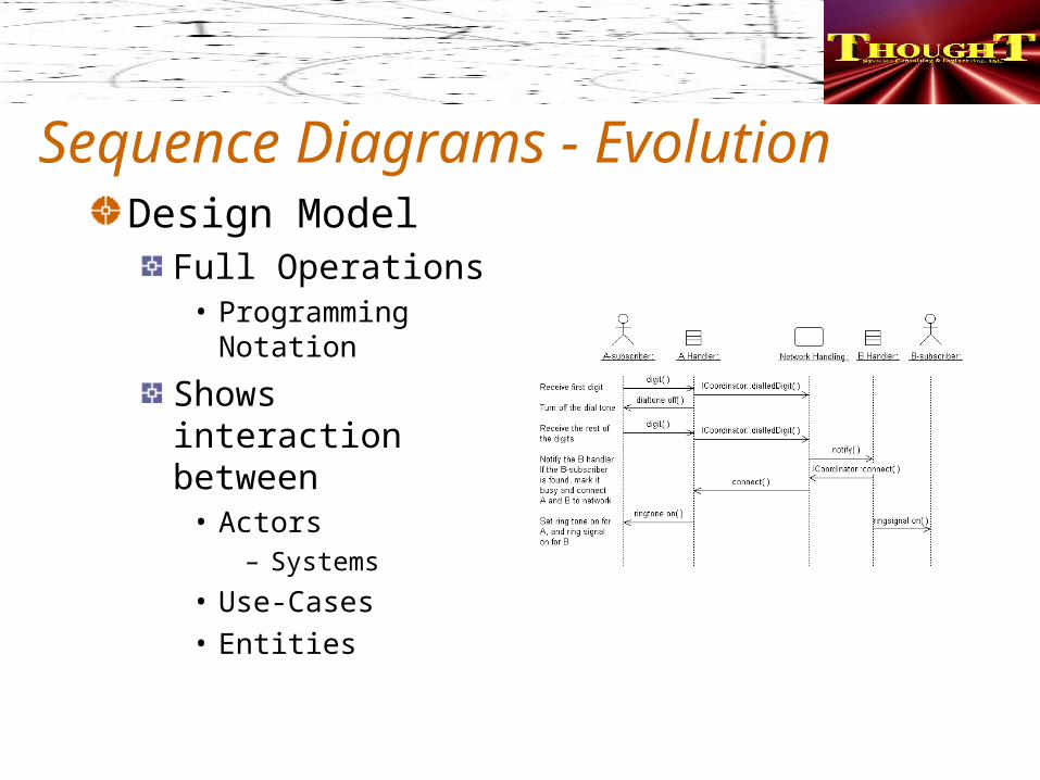
Sequence Diagrams - EvolutionDesign Model
Full Operations• Programming
Notation
Shows interaction between
• Actors– Systems
• Use-Cases• Entities
States & TransitionsA state is a condition of an object in which it performs some activity or waits for an event. A transition is a relationship between two states which is triggered by some event, which performs certain actions or evaluations, and which results in a specific end-state
State MachinesConsists of states, linked by transitions. Used To Model Dynamic Behavior
Event-driven aspects of the system's behavior• Are required for objects who call events and
signal events to implement their operations
State-dependent behavior• Are required for active objects whose
behavior varies base on their state• Are not required for passive objects whose
behavior does not vary with their state
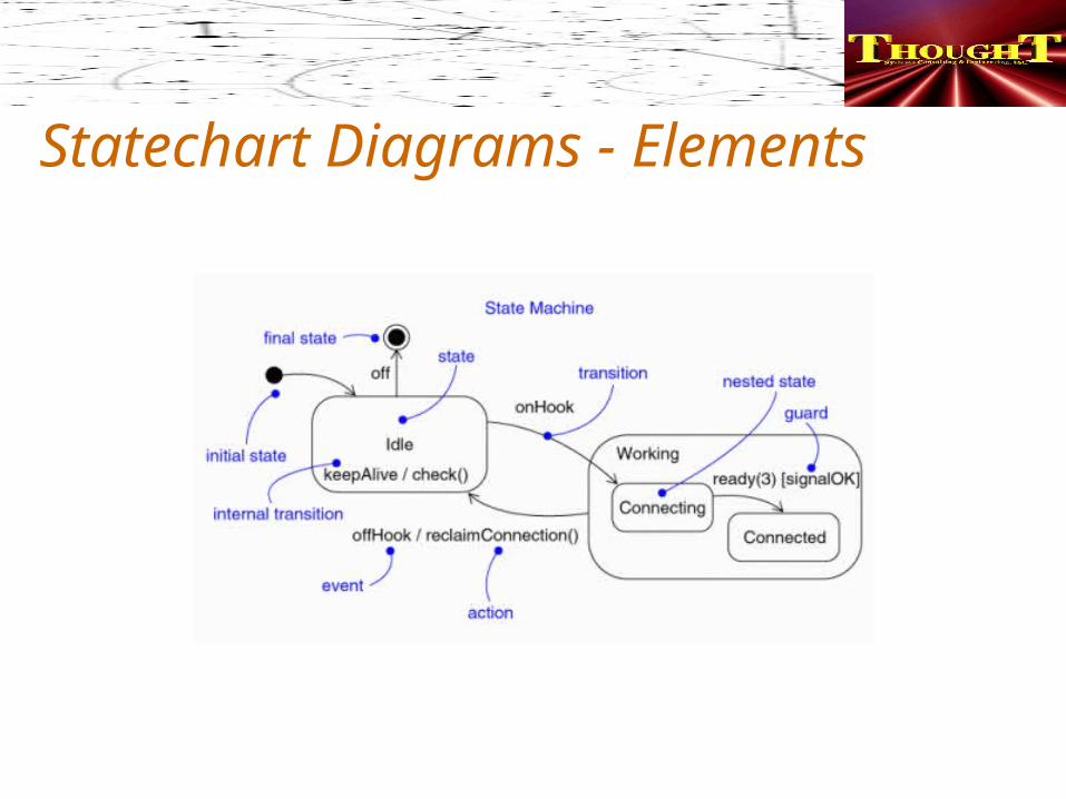
Statechart Diagrams - Elements
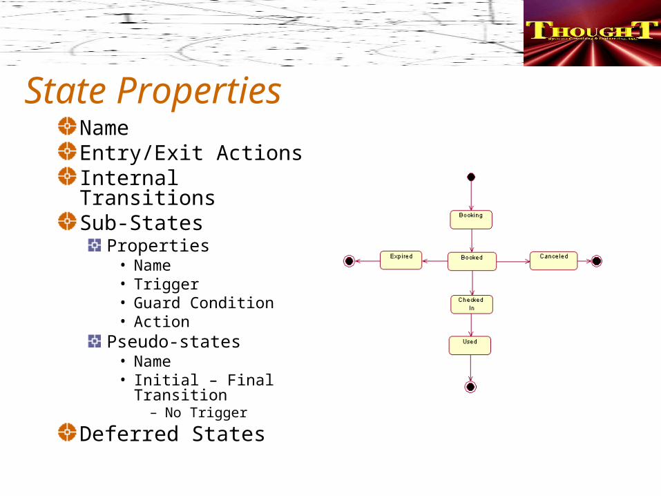
State PropertiesNameEntry/Exit ActionsInternal TransitionsSub-States
Properties• Name• Trigger• Guard Condition• Action
Pseudo-states• Name• Initial – Final
Transition– No Trigger
Deferred States
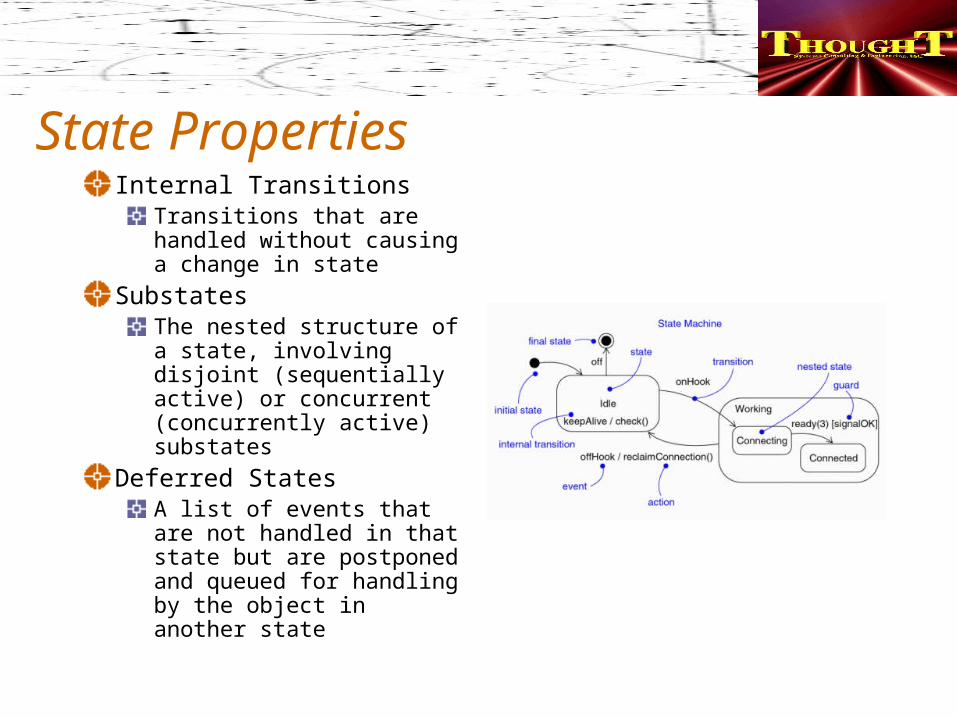
State PropertiesInternal Transitions
Transitions that are handled without causing a change in state
SubstatesThe nested structure of a state, involving disjoint (sequentially active) or concurrent (concurrently active) substates
Deferred StatesA list of events that are not handled in that state but are postponed and queued for handling by the object in another state
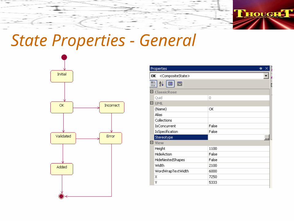
State Properties - General
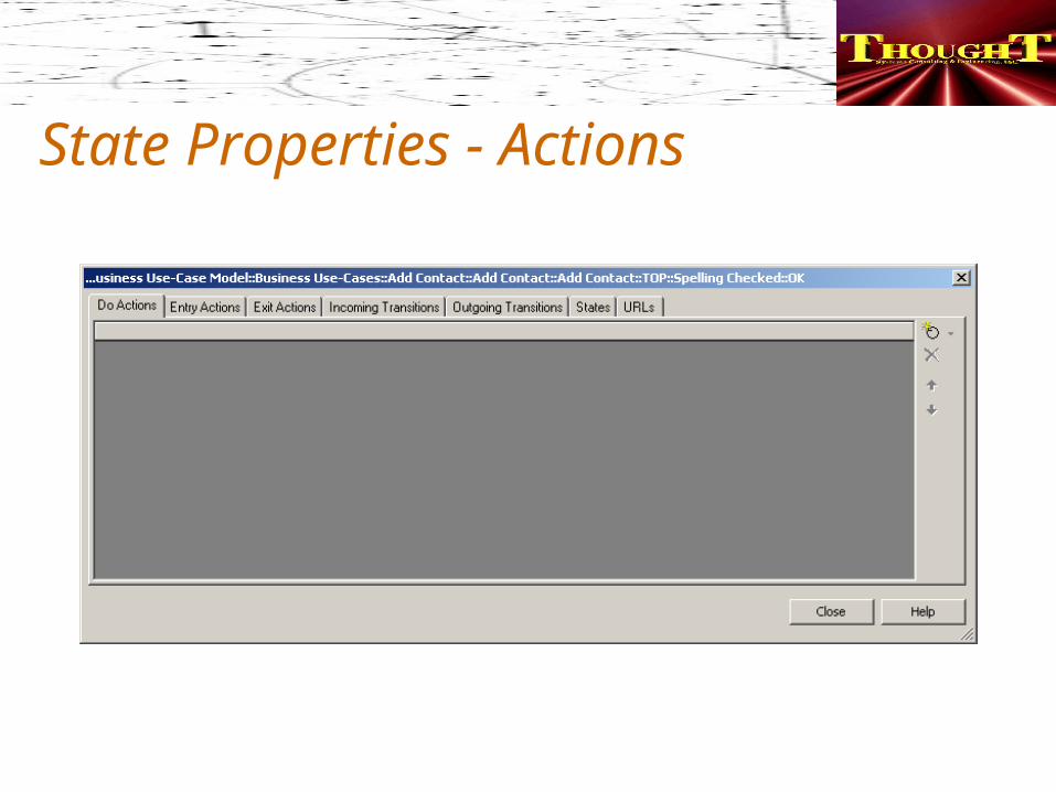
State Properties - Actions
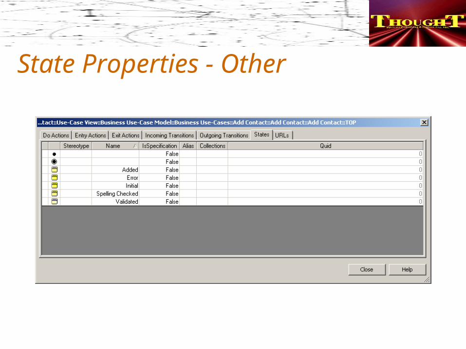
State Properties - Other
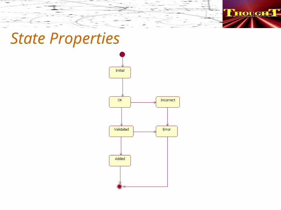
State Properties
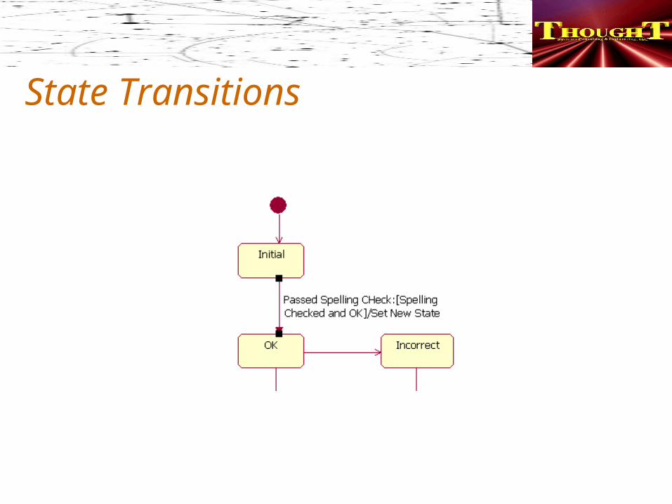
State TransitionsA relationship between two states indicating that an object in the “Source State” will perform certain actions and enter the “Target State” when a specified event occurs and specified conditions are satisfiedTransaction state becomes “Firing”
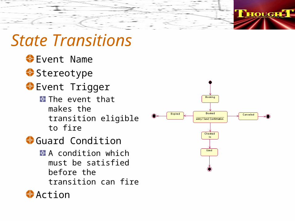
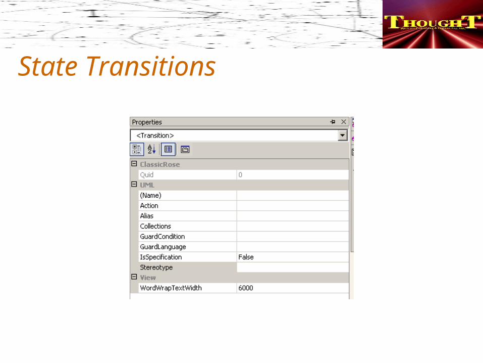
State TransitionsEvent NameStereotypeEvent Trigger
The event that makes the transition eligible to fire
Guard ConditionA condition which must be satisfied before the transition can fire
Action
State Transitions
State Transitions
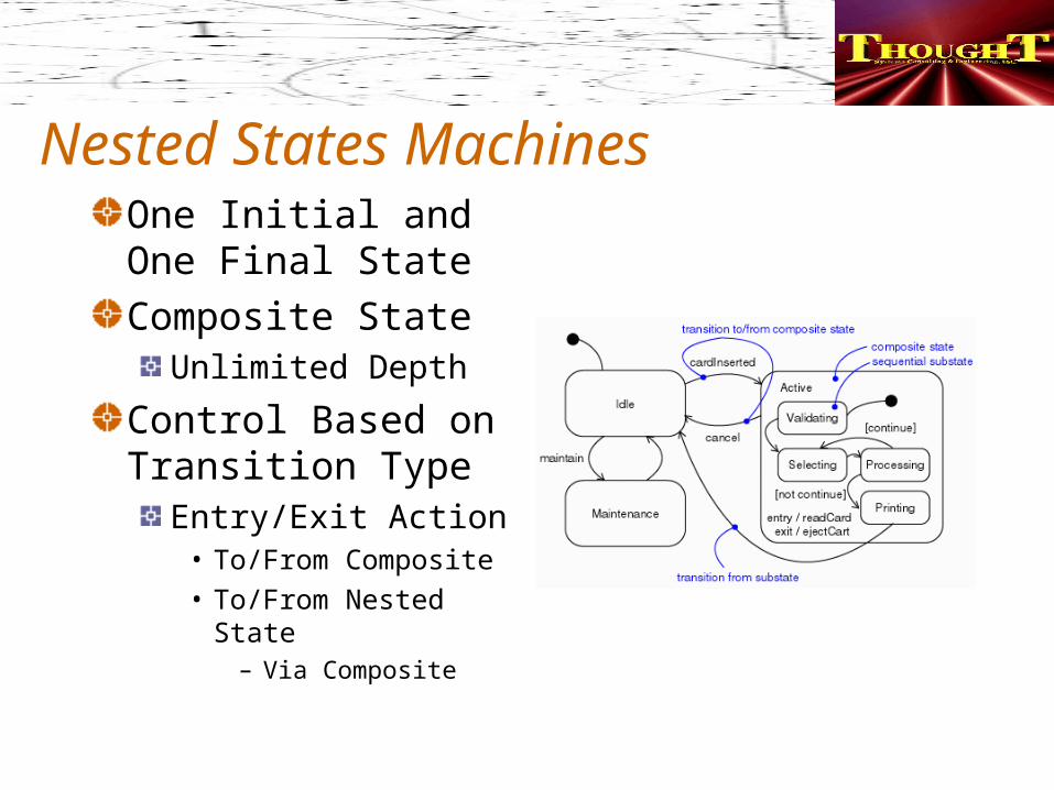
Nested States MachinesOne Initial and One Final StateComposite State
Unlimited Depth
Control Based on Transition Type
Entry/Exit Action• To/From Composite• To/From Nested
State– Via Composite
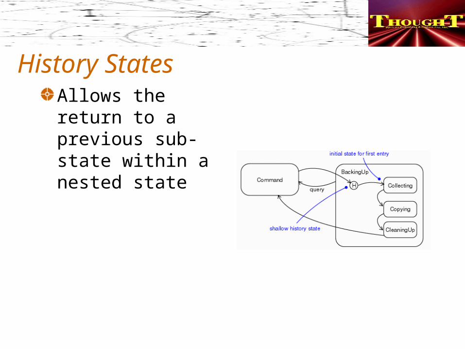
History StatesAllows the return to a previous sub-state within a nested state

Abstract State MachinesNeed to have more detail added before it can be used for practical purposesUtilize Inheritance
Root Class
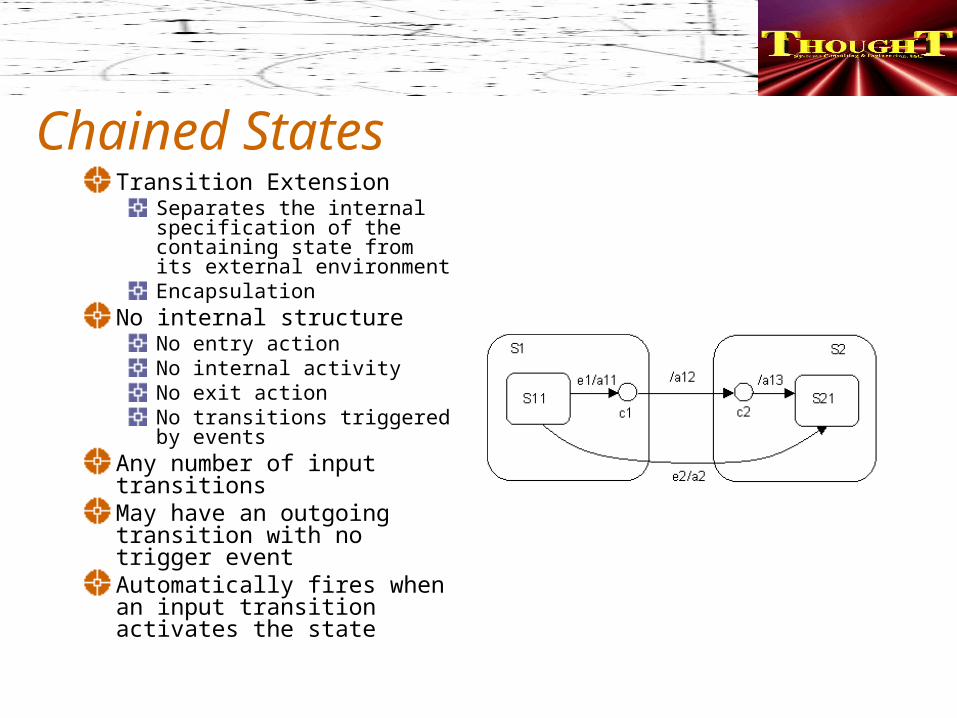
Chained StatesTransition Extension
Separates the internal specification of the containing state from its external environmentEncapsulation
No internal structureNo entry actionNo internal activityNo exit action No transitions triggered by events
Any number of input transitionsMay have an outgoing transition with no trigger eventAutomatically fires when an input transition activates the state
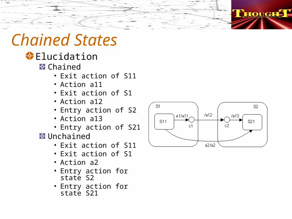
Chained StatesElucidation
Chained• Exit action of S11 • Action a11 • Exit action of S1 • Action a12 • Entry action of S2 • Action a13 • Entry action of S21
Unchained• Exit action of S11 • Exit action of S1 • Action a2 • Entry action for state
S2 • Entry action for state
S21
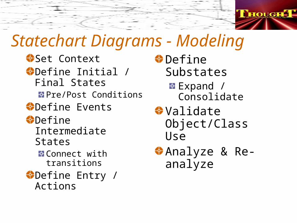
Statechart Diagrams - ModelingSet ContextDefine Initial / Final States
Pre/Post Conditions
Define EventsDefine Intermediate States
Connect with transitions
Define Entry / Actions
Define SubstatesExpand / Consolidate
Validate Object/Class UseAnalyze & Re-analyze
Next StepsHomework
Homework Model• Add Sequence and Statechart Diagrams
– Use modeling elements
Classes AheadCollaboration and Class DiagramsIntegration and Development with the .NET Framework