cr12 cr12 audio/video multizone control system - andovercg
TRANSCRIPT

McIntosh Laboratory, Inc. 2 Chambers Street Binghamton, New York 13903-2699 Phone: 607-723-3512 FAX: 607-724-0549
OWNER�SMANUAL
CR12
CR12 Audio/Video Multizone Control System
20

2
Thank You.......................................................................... 2Please Take a Moment ....................................................... 2Customer Service ............................................................... 2Table of Contents ............................................................... 2Safety Instructions ............................................................. 3Introduction ........................................................................ 4Performance Features ........................................................ 4Pre-Installation .................................................................. 5Installation ......................................................................... 6Rear Panel Controls, Connections and Switches ............... 7How to Connect the CR12 with a C39/MX130................. 8How to Connect Additional CR12�s .................................. 9How to Connect the CR12 in a Stand Alone System ...... 10CR12 Front Panel Displays, Push-Buttons,and Switch ....................................................................... 11How to Operate from the Front and Rear ........................ 12How to Operate in Remote Zones ................................... 13How to Program the CR12 .............................................. 14HR-033 Push-Buttons ...................................................... 16How to Operate by Remote Control ................................ 17Specifications .................................................................. 18Packing Instructions ........................................................ 19
NOTES:1. Up to four sensors or keypads can be wired in parallel for a
single zone.2. For additional information on Video and Audio connections ,
refer to the owner�s manual(s) for the component(s).
Serial Number:
Purchase Date:
Dealer Name:
Customer Service
Copyright 1997 by McIntosh Laboratory, Inc.
Thank You, Please Take A Moment,Customer Service and Table of Contents
Thank You
Please Take A MomentThe serial number, purchase date and McIntosh dealer nameare important to you for possible insurance claim or futureservice. The serial number is located on the rear panel of theequipment. The spaces below have been provided for you torecord that information:
For your decision to own this McIntosh CR12 Auido/VideoMultizone Control System ranks you at the very top amongdiscriminating music listeners. You now have �The Best.�The McIntosh dedication to �Quality,� is assurance that youwill receive many years of musical enjoyment from thisunit.
Please take a short time to read the information in thismanual. We want you to be as familiar as possible with allthe features and functions of your new McIntosh CR12.This will ensure that you receive all the performance ben-efits this equipment can offer you, and that it will become ahighly valued part of your home entertainment system.
If at any time you have questions about your CR12 Auido/Video Multizone Control System, please contact:
McIntosh Laboratory, Inc.2 Chambers StreetBinghamton, New York 13903Phone: 607-723-3512FAX: 607-724-0549
Table of Contents
3
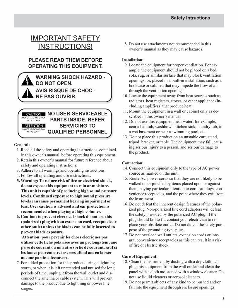
IMPORTANT SAFETYINSTRUCTIONS!
PLEASE READ THEM BEFOREOPERATING THIS EQUIPMENT.
Safety Intructions
WARNING SHOCK HAZARD -DO NOT OPEN.AVIS RISQUE DE CHOC -NE PAS OUVRIR.
NO USER-SERVICEABLEPARTS INSIDE. REFER
SERVICING TOQUALIFIED PERSONNEL
General:1. Read all the safety and operating instructions, contained
in this owner�s manual, before operating this equipment.2. Retain this owner�s manual for future reference about
safety and operating instructions.3. Adhere to all warnings and operating instructions.4. Follow all operating and use instructions.5. Warning: To reduce risk of fire or electrical shock,
do not expose this equipment to rain or moisture.This unit is capable of producing high sound pressurelevels. Continued exposure to high sound pressurelevels can cause permanent hearing impairment orloss. User caution is advised and ear protection isrecommended when playing at high volumes.
6. Caution: to prevent electrical shock do not use this(polarized) plug with an extension cord, receptacle orother outlet unless the blades can be fully inserted toprevent blade exposure. Attention: pour pevenir les chocs elecriques pasutiliser cette fiche polarisee avec un prolongateur, uneprise de courant ou un autre sortie de courant, sauf siles lames peuvent etre inserees afond ans en laisseraucune partie a decouvert.
7. For added protection for this product during a lightningstorm, or when it is left unattended and unused for longperiods of time, unplug it from the wall outlet and dis-connect the antenna or cable system. This will preventdamage to the product due to lightning or power linesurges.
8. Do not use attachments not recommended in thisowner�s manual as they may cause hazards.
Installation:9. Locate the equipment for proper ventilation. For ex-
ample, the equipment should not be placed on a bed,sofa, rug, or similar surface that may block ventilationopenings; or, placed in a built-in installation, such as abookcase or cabinet, that may impede the flow of airthrough the ventilation openings.
10. Locate the equipment away from heat sources such asradiators, heat registers, stoves, or other appliance (in-cluding amplifiers) that produce heat.
11. Mount the equipment in a wall or cabinet only as de-scribed in this owner�s manual
12. Do not use this equipment near water; for example,near a bathtub, washbowl, kitchen sink, laundry tub, ina wet basement or near a swimming pool, etc.
13. Do not place this product on an unstable cart, stand,tripod, bracket, or table. The equipment may fall, caus-ing serious injury to a person, and serious damage tothe product.
Connection:14. Connect this equipment only to the type of AC power
source as marked on the unit.15. Route AC power cords so that they are not likely to be
walked on or pinched by items placed upon or againstthem, paying particular attention to cords at plugs, con-venience receptacles, and the point where they exit fromthe instrument.
16. Do not defeat the inherent design features of the polar-ized plug. Non-polarized line cord adapters will defeatthe safety provided by the polarized AC plug. If theplug should fail to fit, contact your electrician to re-place your obsolete outlet. Do not defeat the safety pur-pose of the grounding-type plug.
17. Do not overload wall outlets, extension cords or inte-gral convenience receptacles as this can result in a riskof fire or electric shock.
Care of Equipment:18. Clean the instrument by dusting with a dry cloth. Un-
plug this equipment from the wall outlet and clean thepanel with a cloth moistened with a window cleaner. Donot use liquid cleaners or aerosol cleaners.
19. Do not permit objects of any kind to be pushed and/orfall into the equipment through enclosure openings.

4
Performance Features
Safety Instructions con�t,Introduction and Performance Features
Never spill liquids into the equipment through enclosureopenings.
20. Unplug the power cord from the AC power outlet whenleft unused for a long period of time.
Repair of Equipment:21. Unplug this equipment from the wall outlet and refer
servicing to a qualified service personnel under the fol-lowing conditions:A. The AC power cord or the plug has been damaged,B. Objects have fallen, or liquid has been spilled into
the equipment,C. The equipment has been exposed to rain or water,D. The equipment does not operate normally by follow-
ing the operating instructions contained within thisowner�s manual. Adjust only those controls that arecovered by the operating instructions, as an im-proper adjustment of other controls may result indamage and will often require extensive work by aqualified technician to restore the product to its nor-mal operation,
E. The equipment has been dropped or damaged in anyway,
F. The equipment exhibits a distinct change in perfor-mance - this indicates a need for service.
22. Do not attempt to service beyond that described in theoperating instructions. All other service should be re-ferred to qualified service personnel.
23. When replacement parts are required, be sure the ser-vice technician has used replacement parts specified byMcIntosh or have the same characteristics as the origi-nal part. Unauthorized substitutions may result in fire,electric shock, or other hazards.
24. Upon completion of any service or repairs to this prod-uct, ask the service technician to perform safety checksto determine that the product is in proper operating con-dition.
Introduction
· Four Independent PreampliersThe CR12 consists of four independent stereo Audio/Videopreamplifiers that can be remotely controlled from fourseparate zones.
· Separate ProgrammingEach of the four zones can be programmed from the CR12front panel for selection of signal source and wakeup vol-ume level.
· Eight Source SelectionSelect any of four stereo audio/video signal sources, andfour stereo audio signal sources in each zone using a key-pad or Remote Control.
· Local Source Zone SelectionAn audio/video or audio signal source component can bededicated to operate only in a specific zone.
· Independent Zone Tone AdjustmentIndividual bass and treble controls for each zone allow toneshaping to optimize audio performance for different speak-ers and room acoustics.
· Video SwitchingMatched and buffered video switching ensures perfect pic-ture integrity from the latest high resolution video sources.
· Font Panel Zone DisplayThe front panel display shows the status of each zone.
· Accepts all McIntosh KeypadsThree different McIntosh keypad models can be used withthe CR12.
· Four Keypads and/or Sensors per ZoneEach remote zone can accommodate up to four keypads orwall sensors to select and operate all the available signalsource components.Now you can take advantage of traditional McIntosh stan-
dards of excellence in the CR12 advanced design Audio/Video Multizone Control System. You only need to push abutton on a remote controller or a keypad to enjoy musicand video programs throughout your home with McIntoshquality and reliability. The heart of the CR12 consists offour, independent. remotely controlled stereo preamplifiers.

5
If the CR12 is interconnected with a McIntosh C39 orMX130 A/V Control Center, and both components are lo-cated together, the internal front panel IR sensor must bedisabled. This avoids interference problems caused bysending IR commands simultaneously to the front panelsensors of BOTH units.
1. Remove the top cover of the CR12.
2. With the CR12 front facing you, locate a small slideswitch on the large vertical circuit board near the top ofthe right side behind the front panel.
3. Move the switch to the Right.
Pre-Installation
CR12 Front Panel Sensor Disabling
Keypad Terminal ConnectorTo use a WK-3 or WK-4 keypad, connect the shield andfour leads of a shielded 4 conductor cable to a keypad ter-minal connector, according to the numbers listed below.There is a similar numbered connector built-in to each key-pad.
1. Supply Voltage Positive2. Supply Voltage Ground3. Cable Shield4. Signal Data5. Signal Data Ground
Din Connector Pin Layouts for Balanced Outputs1. Left Channel (-)2. (Not used)3. Right Channel(-)4. Left Channel Ground5. Right Channel Ground6. Left Channel (+)7. Right Channel (+)
Connector Information
Connecting Cables and ConnectorsConnecting Cables and Connectors are available from theMcIntosh Parts Department:
Data and Power Control Cable Part No. 170-202Six foot, shielded 2 conductor, with 118 inch stereomini phone plugs on each endControl Center to CR12 Cable Part No. 170-203Three foot, DB25, Shielded, straight through, 25 con-ductor male-to-male cable.CR12 to CR12 Cable Part No. 170-430Six foot, DB3 7, shielded, straight through, 3 7 conduc-tor male-to-male cable.Control Center to Multi Channel Power AmplifierCable Part No. 170-631Six foot, DB25, shielded, straight through, 25 conduc-tor male-to-female cable.CR12 Keypad Terminal Plug Part No. 117-634Five Pin connector for attaching the 4 conductor cableto the CR12 Keypad Socket.
Located inside the CR12

6
InstallationThe CR12 can be placed upright on a table or shelf, stand-ing on its four feet. It also can be custom installed in apiece of furniture or cabinet of your choice. The requiredpanel cutout, ventilation cutout and unit dimensions areshown.
Always provide adequate ventilation for your CR12.Cool operation ensures the longest possible operating lifefor any electronic instrument. Do not install the CR12 di-rectly above a heat generating component such as a highpowered amplifier. If all the components are installed in asingle cabinet, a quiet running ventilation fan can be a defi-
Installation
17-1/2"444mm
17-1/16"433.4mm
7/32"5.3mm
Support Shelf
Outline of Front Panel
Edge of Cutout
Panel Height 7.00" 177.8mm
6-9/16" 166.7mm
1/4"6mm
3/16"5.1mm
End Caps7-1/16"179.8mm
Bottom of Cutout and Topof Support Shelf MustCoincide
Mounting Surface
Outline of Unit
(Side View)
Support Shelf
Mounting Bracket at Both Sides of the Rear Panel.Fasten with 6-32 x 3/8 Machine Screw and Washer to Chassis.Fasten with 6 x 1/2 Wood Screw and Washer to Support Shelf
6"
15"
9"
Mounting Surface
Cut Out Centerfor Ventilation
(Bottom View)
(Front View)
Cut Out Centerfor Ventilation
FrontView of a CR12custom installed
nite asset in maintaining all the system components at thecoolest possible operating temperature.
A custom cabinet installation should provide the follow-ing minimum spacing dimensions for cool operation. Allowat least 1-1/2 inches (3.8cm) above the unit so airflow isnot obstructed. Allow 17-1/2 inches (44.5cm) depth behindthe mounting panel, which includes clearance for connec-tors. Allow 1-1/8 inches (2.9cm) in front of the mountingpanel for knob clearance. Be sure to cut out a ventilationhole in the mounting shelf according to the dimensions inthe drawing.
Side View of a CR12custom installed
Bottom View of a CR12custom installed

7
CR12 Rear Panel Controls,Connections and Switches
CR12 Rear Panel Controls, Connections andSwitches
Connect the CR12power cord to a liveAC outlet. Refer toinformation on theback panel to deter-mine the correctvoltage
EXT (external)SENSOR for aMcIntosh Key-pad or IR sensor
DATA PORTs sendsignals to compatiblesource components toallow you to remotelycontrol them.
PWR CTL sendsa turn-on signalto a McIntoshComponent
BALANCEDOUTPUTSsends signalsto power am-plifier inputsand the switchthat selectsFixed or Vari-able Outputs
HOME Data Portconnects to the op-tional HC-1 HomeController
UNBALancedOUTPUTS feedsignals to poweramplifier inputs
AUDIO INPUTS acceptsignals from the outputsof source components.
BASS and TREBLEcontrols provides±12dB adjustmentfrom the flat centerposition
TO NEXT CONTROLLERconnects to the next CR12Controller Input B
CONTROLLER INPUTA connects to a McIntoshA/V Control Center
Dedicated LocalZone Audio/Video SignalSource
Keypad connectorallows use ofWK-3 or WK-4keypads
Level control pro-vides ± 6dB adjust-ment, for themaximun volumelevel, from the cen-ter position
MULTI-CHANNELAMP, connects to aMcIntosh multi-chan-nel power amplifier
MULTI-CHANNELconnector whichsends a turn on sig-nal to a McIntoshmulti-channel poweramplifier
RS232 connectorfor future usewith an adapter(supplies Dataand Power)
VIDEO INPUTSfor Video signalsource components
VIDEO OUTPUTS to send videosignals to another CR12 or to aMcIntosh Control Center
POWER CON-TROL Outputssend turn-on sig-nals to a McIntoshPower Controller
VIDEO OUT TOMONitor sends avideo signal to amonitor/TV
CONTROLLER INPUT Bconnects to the previousCR12 to next controlleroutput

8
McIntosh Audio/Video Control Center
McIntosh PC-3
How to Connect the CR12with a C39/MX130
To AC Outlet
How to Connect the CR12 with a C39/MX130
McIntosh LD Player
123456789123456789123456789123456789123456789123456789123456789123456789123456789123456789123456789123456789
123456789123456789123456789123456789123456789123456789123456789123456789123456789123456789123456789123456789
LeftLoudspeaker
RightLoudspeaker
Zone 1 Room
McIntoshKeypad
Monitor/TV
�Y�Adapter
To PC-3 ACOutlets
McIntosh Tuner
Dedicated ZoneSource Component
To PC-3 ACOutlet
McIntosh Multi-Channel Amplifier
1. Connect the CR12 power cord to a live AC outlet.2. Connect a McIntosh Power Controller to the CR12 us-
ing either the Din or Pwr Ctl connector and connectzone amplifier power cords to the appropriate outletson the Power Controller.
3. Connect a McIntosh multi channel amplifier with aDB25 computer type cable from the CR12 Multi-Chan-nel Amp connector to amplifier input connector.
Note: Both audio and zone power control pass through thiscable. Discrete zone audio cables may also be used,either balanced or unbalanced. Refer to on Page 5 forthe Din plug balanced terminal connections. Alsoconnect a cable from the CR12 Din Multi-Channel Ampconnector to the matching connector on the amplifier toprovide zone power control.
4. Connect a WK-3/WK-4 keypad, using 4 conductorshielded cable to a zone terminal connector or connecta WK-2 keypad or R649 wall sensor to a zone sensorconnector with RG6 or RG59U coax cable.
5. Connect the video outputs of A/V source components tothe CR12 video inputs and the CR12 video outputs to
the matching C39/MX130 video inputs.6. Connect the Audio Outputs from A/V source compo-
nents to both the CR12 and C39/MX130 inputs using a�Y� adapter if necessary.
7. For dedicated zone source components, connect theirAudio, Video and Data outputs to the CR12 Zone AuxIn connectors.
Note: The A/V source signals used in a dedicated zone replacethe Aux signal source selection and are automaticallyswitched when a plug is inserted into the Data port. If nodata cable is used, insert 1/8 inch mini Stereo phoneplug, (with a lead connected from the tip to the ring), toactivate the switching.
8. Connect the Video Out to Mon to the Video input of aremote zone TV or monitor.
9. Connect a DB25 cable from the CR12 Controller InputA Connector to the To Multi-Room Controller connec-tor on a McIntosh Control Center.
NOTE: The DB25 cable passes only the CD2, Tuner, Tape 1and Aux audio along with matching Data, Sys Off andPower Control signals from the control center to theCR12.

9
How to ConnectAdditional CR12�s
How to Connect Additional CR12�s
McIntosh PC-3
First CR12 for Zones 1-4
Second CR12 for Zones 5-8
To AC Outlet
To AC Outlet
To Third CR12Controller Input B
McIntosh LD Player
To Third CR12LV Video Input
To PC-3AC Outlet
McIntosh Multi-Channel Amplifier
McIntosh Multi-Channel Amplifier
As many as six CR12�s can be cascaded to supply audioand video to a maximum of 24 zones. Cascaded CR12�scan also be connected with a McIntosh Control Center,which adds two additional zones.
1. Connect a DB37 shielded 37 conductor cable from theTo Next Controller socket of the first CR12, to theController Input B of the second CR12. All Audio sig-nals and the audio portion of A/V sources connected tothe first CR12 will be sent down the cable to each suc-ceeding CR12 to allow all remote zones to receive au-dio from all the Audio/Video sources.
2. Connect video cables from the video outputs of the firstCR12 to the video inputs of the second CR12.
3. Repeat the video connections in and out of each CR12.
4. When cascaded CR12 systems are used with a McIn-tosh Control Center, connect the video outputs of thelast CR12 to the matching video inputs of the controlcenter

10
How to Connect the CR12in a Stand Alone System
How to Connect the CR12 in a Stand AloneSystem
McIntosh PC-3
To AC Outlet
McIntosh LD Player
123456789123456789123456789123456789123456789123456789123456789123456789123456789123456789123456789123456789
123456789123456789123456789123456789123456789123456789123456789123456789123456789123456789123456789123456789
LeftLoudspeaker
RightLoudspeaker
Zone 1 Room
McIntoshKeypad
Monitor/TV
To PC-3AC Outlets
McIntosh Tuner
Dedicated ZoneSource Component
To PC-3 ACOutlet
McIntosh Multi-Channel Amplifier
To SecondCR12
To Second CR12
To PC-3AC Outlets
McIntosh CD Player
1. Connect the CR12 power cord to a live AC outlet.2. Connect a McIntosh Power Controller to the CR12 us-
ing either the Din or Pwr Ctl (power control) connectorand connect zone amplifier power cords to the appro-priate outlets on the Power Controller.
3. Connect a McIntosh multi channel amplifier with aDB25 computer type cable from the CR12 Multi-Chan-nel Amp connector to amplifier input connector.
Note: Both audio and zone power control pass through thiscable. Discrete zone audio cables may also be used,either balanced or unbalanced. Refer to Page 5 for theDin plug balanced terminal connections. Also connect acable from the CR12 Din Multi-Channel Amp connectorto the matching connector on the amplifier to providezone power control.
4. Connect a WK-3/WK-4 keypad, using 4 conductorshielded cable to a zone keypad terminal connector orconnect a WK-2 keypad or R649 wall sensor to a zone
sensor connector with RG6 or RG59U coax cable.5. Connect the video outputs of A/V source components to
the CR12 video inputs and audio outputs to CR12 au-dio inputs.
6. For dedicated zone source components, connect theirAudio, Video and Data outputs to the CR12 Zone AuxIn connectors.
Note: The A/V source signals used in a dedicated zone replacethe front panel Aux signal source selection and areautomatically switched when a plug is inserted into theData port. If no data cable is used, insert 1/8 inch miniStereo phone plug, (with a lead connected from the tip tothe ring), into the Data port to activate the switching.
7. Connect the outputs of audio source components to theCR12 audio inputs.
8. Connect the Video Out to Mon to the Video input of aremote zone TV or monitor.

11
CR12 Front Panel Displays, Push-Buttons andSwitch
20
CR12 Front Panel Displays,Push-Buttons and Switch
Allows you todisable controloperations ofaccessory com-ponents in anyzone
Program an ac-cessory turn oncommand whenthat source isselected
LED is on when the ACpower cord is connectedto a live AC outlet, andthe front panel POWERswitch is turned to ON
The LED Displaysindicate what signalsources have beenselected for eachzone
Mutes or unmutesaudio in any zonethat is turned on
Select the zone youwish to program Turns all AC
power on or off
Resets all CR12microprocessors
Select any one of the Audioor Audio/Video signalsources for use in any zone
Turns off the entireMcIntosh Audio/Video System
Program a startplaying com-mand when thatsource is se-lectedThe digital display indi-
cates the % (Percent) ofthe maximum volume forthe zone selected. After 10seconds the display revertsto the volume setting forZone 1
Adjust the volumelevel up or down inany zone
Turns on or off aspecific zone tooperate or to allowprogramming
The LED indicatesif the mute func-tion is active forthe zone selected
The LED�s indi-cate which zonesare turned on
IR Sensor receivescommands from aremote control
The LED�s indicatewhich zones are in theprogramming mode
The LED indicates if thezone selected has the ac-cessory control off com-mand programmed
The LED indicates ifthe zone selected hasthe accessory on com-mand programmed
The LED indi-cates if the zoneselected has thetransport playcommand pro-grammed

12
How to Operate from the Front and RearPanel
Power OnPress the front panel Power switch to turn on the CR12.The power switch is normally left in the on position withthe power cord in a live AC outlet. The red LED power in-dicator will stay on to indicate the CR12 is ready for use.Refer to figure 1.
Note: Turn the power switch off only when the system is notgoing to be used for an extended time.
Zone On/OffTurn on and operate any of the four zones by pressing aZone On/Off push-button. The zone will turn on with thedefault or programmed signal source and volume level.Press the Zone On/Off push-button a second time to turnthe zone off.
Note: If zones 2, 3 or 4 are turned on, all front paneloperating functions return to zone 1 after 10 seconds. Ifno programming has been performed, all zones will turnon to the tuner source at a volume indication of 20.
Reset of MicroprocessorsIn the event that the controls of the CR12 stop functioning,there is a user reset function built in. Press the Reset push-button and this will reset the CR12 microprocessors.
Dedicated zone source componentsIf a specific CR12 zone has a source component dedicatedexclusively to that zone, it can be operated in that zonewith a keypad or remote control. When a dedicated zonesource component is connected, it replaces the source com-ponent that is connected to the CR12 Aux inputs. If theCR12 is connected with a ControlCenter which has a source componentconnected to its Aux inputs, that com-ponent will not be available in thezone with the dedicated source com-ponent.
System OffNormally remote zones are turned onand off individually in each respec-tive zone by pressing the Power push-button on a keypad or remote control.
If you desire to turn off all zones of an entire CR12 systemsimultaneously, including a control center and accessorysource components, you can press the Sys Off push-buttonon the front panel,. You can also turn off the entire systemin any remote zone by pressing the Sys Off push-button ona keypad or remote control.
Note: Individual remote zones should normally be turned offwith the Power push-button since there may be otherzones in use that would automatically be turned off bythe Sys Off push-button in a specific zone.
Bass, Treble and Level ControlsAdjust the bass and treble controls for the desired toneshaping in each zone.Adjust the zone levelcontrols to increase ordecrease a maximum of6dB from the center de-tent position. Volumechanges with the levelcontrols add or subtractfrom the turn on levels.Refer to figure 2.
Balanced and UnBalanced OutputsPlace the slide switch to the correct position according tothe output hook-up, balanced or unbalanced connections.
How to Operate from the Frontand Rear Panel
2 6
Figure 1
Figure 2
13
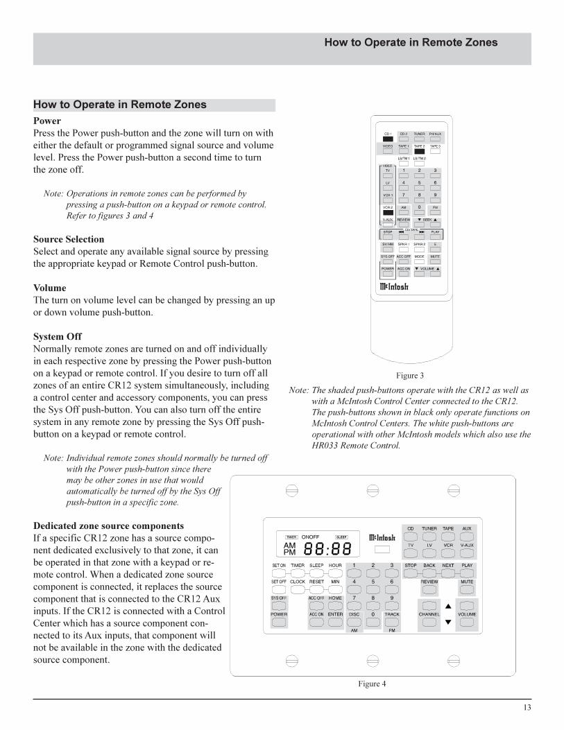
PowerPress the Power push-button and the zone will turn on witheither the default or programmed signal source and volumelevel. Press the Power push-button a second time to turnthe zone off.
Note: Operations in remote zones can be performed bypressing a push-button on a keypad or remote control.Refer to figures 3 and 4
Source SelectionSelect and operate any available signal source by pressingthe appropriate keypad or Remote Control push-button.
VolumeThe turn on volume level can be changed by pressing an upor down volume push-button.
System OffNormally remote zones are turned on and off individuallyin each respective zone by pressing the Power push-buttonon a keypad or remote control. If you desire to turn off allzones of an entire CR12 system simultaneously, includinga control center and accessory components, you can pressthe Sys Off push-button. You can also turn off the entiresystem in any remote zone by pressing the Sys Off push-button on a keypad or remote control.
Note: Individual remote zones should normally be turned offwith the Power push-button since theremay be other zones in use that wouldautomatically be turned off by the Sys Offpush-button in a specific zone.
Dedicated zone source componentsIf a specific CR12 zone has a source compo-nent dedicated exclusively to that zone, it canbe operated in that zone with a keypad or re-mote control. When a dedicated zone sourcecomponent is connected, it replaces the sourcecomponent that is connected to the CR12 Auxinputs. If the CR12 is connected with a ControlCenter which has a source component con-nected to its Aux inputs, that component willnot be available in the zone with the dedicatedsource component.
How to Operate in Remote Zones
How to Operate in Remote Zones
Figure 3
Figure 4
Note: The shaded push-buttons operate with the CR12 as well aswith a McIntosh Control Center connected to the CR12.The push-buttons shown in black only operate functions onMcIntosh Control Centers. The white push-buttons areoperational with other McIntosh models which also use theHR033 Remote Control.

14
1. Press a Program push-button for the zone you wish toturn on and program. The LED next to the selectedzone will turn on.
Note: After pressing a Program push-button, you must makeany programming selections with 10 seconds of eachother. If no further selection is made within 10 seconds,the zone programming will turn off and the CR12 frontpanel reverts to Zone 1 control. If the zone is alreadyturned on when programming is initiated, the zoneaudio will mute and any video signals will blank aswell.
2. Select a signal source for the zone by pressing any ofthe eight signal source push-buttons. The selected sig-nal source front panel LED will turn on for the zonebeing programmed. This will becomethe active signal source wheneverthat zone is turned on.
3. Press an Up or Down Volume push-button to select the desired volumelevel in the zone being programmed.The front panel display will indicatethe selected level.
4. Press Program again or wait 10 sec-onds to exit the programming mode.
1. Press the Program push-button for the zone you to wishchange.
2. Press the push-button for the signal source whose LEDis currently illuminated. The entire row of front panelsignal source LED�s for that zone will turn off.
3. Press Program again or wait 10 seconds to exit the pro-gramming mode.
4. The next time the zone is turned on it will come onwith the last selected signal source and volume level.
1. Press the Program push-button for the zone requiringAccessory on.
2. Press the push-button for the signal source requiring anaccessory on command.
3. Press Accessory On to program a turn on signal. TheLED next to the Accessory On push-button will turnOn to indicate accessory on command has been se-lected.
4. Press Program again or wait 10 seconds to exit the pro-gramming mode.
Note: The accessory source component must have a Datacable interconnected with the CR12 in order to receivethe turn on command and must also have a powerswitch that automatically cycles off when AC power isremoved.
How to Program the CR12
Introduction to ProgrammingIf no programming is performed, each zone will turn onwith the default tuner signal source at an indicated volumelevel of 20. You can program a desired signal source andvolume level for each separate zone which will appear ev-ery time that zone is turned on. It is also possible to changeprogramming so the zone will turn on with the last selectedsignal source and volume level. You can also program acompatible source component such as a CD player to turnon and start playing when the zone is first turned on. It isalso possible to program accessory source function controloff for a zone which allows listening or viewing withoutbeing able to operate accessory source component func-tions. All programming is stored in permanent memory andis retained until changed, even in the event of a power fail-ure. Refer to Figure 5.
How to program a zone with the same signalsource and volume level
How to program a zone with the last selectedsignal source and volume level
How to program Accessory On
Figure 5

15
How to Program the CR12con�t
If the selected signal source is a component with a Playfunction, such as a CD player, Video Disc player or taperecorder, you can program to have the player start in Playmode after its power turns on.
1. Press the Program push-button for the zone requiring aTransport Play command.
2. Press the push-button for the signal source requiring thetransport play command.
3. Press the Transport Play push-button. The LED next tothe Transport Play push-button will turn on to indicatethe transport play command has been selected.
Note: Programming Accessory source on in combinationwith Transport Play adds a 2 second time delay af-ter a zone is turned on.
4. Press Program again or wait 10 seconds to exit the pro-gramming mode.
How to program Transport Play
1. Press the program push-button for the zone requiringAccessory source Control Off.
2. Press the push-button for the signal source requiringAccessory source Control Off.
3. Press the Accessory Control Off push-button. The RedLED to the right of the Accessory Control Off push-button will turn ON to indicate that the Control func-tion is OFF.
Note: Any source components connected for use in adedicated zone will not be affected by the Accessorysource Control Off function.
4. To exit the programming mode, press a Program push-button again or wait 10 seconds.
How to program accessory control off
To change the previously programmed wakeup or turn onsignal source and volume level, using a keypad or remotecontrol.
1. Press a push-button for the desired new signal source.
2. Adjust the volume to the desired level.
3. Press and hold the new signal source push-button for 3seconds.
4. The zone audio will mute, indicating that the changehas occurred. Release the push-button to unmute.
5. The next time that zone is turned on, the new signalsource and volume level will be in effect.
Remote Zone Programming with a keypad orremote control
16
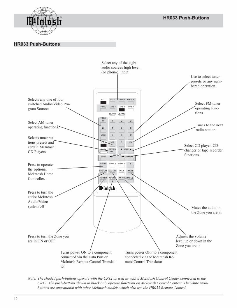
HR033 Push-Buttons
HR033 Push-Buttons
Select any of the eightaudio sources high level,(or phono), input.
Selects any one of fourswitched Audio/Video Pro-gram Sources
Adjusts the volumelevel up or down in theZone you are in
Selects tuner sta-tions presets andcertain McIntoshCD Players.
Select CD player, CDchanger or tape recorderfunctions.
Press to operatethe optionalMcIntosh HomeController.
Press to turn theentire McIntoshAudio/Videosystem off
Press to turn the Zone youare in ON or OFF
Use to select tunerpresets or any num-bered operation.
Select FM tuneroperating func-tions.
Select AM tuneroperating functions.
Mutes the audio inthe Zone you are in
Tunes to the nextradio station.
Turns power ON to a componentconnected via the Data Port orMcIntosh Remote Control Transla-tor
Turns power OFF to a componentconnected via the McIntosh Re-mote Control Translator
Note: The shaded push-buttons operate with the CR12 as well as with a McIntosh Control Center connected to theCR12. The push-buttons shown in black only operate functions on McIntosh Control Centers. The white push-buttons are operational with other McIntosh models which also use the HR033 Remote Control.

17
How to Operate the HR033
How to Operate HR033VideoPress any of the four video signal source push-buttons toturn the zone on and select the video signal source for use.
CD/TapeWhen a CD Player or Tape Recorder is selected, the fol-lowing operations are possible. Stop, Back Track, NextTrack, and Play.
HomePress the Home push-button, and within 5 seconds, the ap-propriate number push-buttons (0 through 9) to operate theoptional HC-1 Home Controller which in turn will controlpower to accessories.
Sys OffPress Sys Off (System Off), to turn off the entire McIntoshAudio/Video system. (This function is not possible in azone that has been programmed for a priority AccessoryControl lockout.)
PowerPress Power to turn on the zone where the Remote Controlis located.
Acc On / Acc OffPress the Acc On push-button to turn power on of ansource component connected to the CR12 System and pro-grammed. If a McIntosh Remote Control Translator is con-nected, press the Acc Off. to turn power Off of an acces-sory component connected to the CR12 System.
CD2, Tuner, PH/Aux and Tape 1Press any of these push-buttons to select the desired audiosignal source.
0 through 9 Push-buttonsPress one or more numbered push-buttons for any functionrequiring direct number key access. This could be operat-ing the HC-1 Home Controller, accessing tuner station pre-sets, accessing tracks on a McIntosh MCD7009 CD Player,MLD7020 Laser Video Disc Player, or any similar functionrequiring direct key access. These push-buttons also can beused to operate accessory components interconnected witha McIntosh Remote Control Translator.
Tuner Push-buttonsUse with a McIntosh tuner. Select AM or FM broadcastband. Press and release SEEK Up or Down to move fromstation to station. Press and hold a SEEK push-button tomove continuously from station to station. Press REVIEWto start the automatic brief audition of each of the presetsstored in the tuner memory. Press REVIEW a second timeto stop on a station preset and exit the Review process.
E (Enter)Press E (Enter) to activate a programming process requiredby an accessory component connected to the CR12 with aMcIntosh Remote Control Translator.
MutePress Mute to silence or mute audio in any zone where theRemote Control is being used. Press Mute again, adjust themain volume or switch to a different signal source tounmute.
Volume Up or DownPress these push-buttons to raise or lower volume in anyzone where the remote control is being used.
Note: Remote Control Push-button Additional Functions when aMcIntosh MCD7009 or MLD720 is being used:
CR12 Push-Button MCD7009 Function MLD7020 FunctionReview +10 +10Seek Down REVerse REVerseSeek Up FF (Fast Forward) FF (Fast Forward)E (Enter) Pause PauseAM Side AFM Side BACC On Power

18
Specifications
Frequency Response+0, -0.5dB from 20Hz to 20,000Hz
Total Harmonic Distortion0.01% From 20Hz to 20,000Hz
Signal To Noise Ratio90dB below rated output, (A Weighted)
Sensitivity250mV for 1.5V rated output
Input Impedance22K ohms
Output Impedance600 ohms, Balanced and Unbalanced
Maximum Input Signal8Volts
Maximum Voltage Output6Volts
Voltage GainInput to Variable Outputs, 14dBInput to Fixed (Balanced) Outputs, 0dB
Tone Controls+12dB, -12dB from center detent position
Power Requirements100 Volts, 50/60Hz at 25 watts.110 Volts, 50/60Hz at 25 watts.120 Volts, 50/60Hz at 25 watts.220 Volts, 50/60Hz at 25 watts.230 Volts, 50/60Hz at 25 watts.240 Volts, 50/60Hz at 25 watts.
NOTE: Refer to the rear panel of the CR12 for the correctvoltage
Dimensions17-1/2 inches (44.5cm) W, 7-1/16 inches (17.9cm) H, 20inches (50.8cm) D, (including clearance for connectors)
Specifications

19
Packing Instructions
In the event it is necessary to repack the equipment for ship-ment, the equipment must be packed exactly as shown be-low. It is very important that the four plastic feet are at-tached to the bottom of the equipment. This will ensure theproper equipment location on the bottom pad. Failure to dothis will result in shipping damage.
Use the original shipping carton and interior parts only ifthey are all in good serviceable condition. If a shipping car-ton or any of the interior part(s) are needed, please call orwrite Customer Service Department of McIntosh Labora-tory. Please see the Part List for the correct part numbers.
Quantity Part Number Description1 033762 Shipping carton only2 033763 End Cap
1 033620 Inside carton only1 033726 Top Pad1 033729 Bottom pad
4 018578 Plastic foot4 100159 #10-32 x 3/4� screw4 104080 #10 Flat washer
1 047920 Shipping carton complete withall the above parts
Packing Instructions
TopPad
Unit with (4)feet on BottomCover
Foot (4)
10-32 x -3/4�screws withwashers
BottomPad
InsideCarton
IMPORTANT(Read Above)
End Cap
InsideCarton
ShippingCarton

McIntosh Part No. 04042001
McIntosh Laboratory, Inc.2 Chambers Street
Binghamton, NY 13903