coupling grain boundary motion to shear deformationphysics.gmu.edu/~ymishin/coupling.pdf ·...
TRANSCRIPT

www.actamat-journals.com
Acta Materialia 54 (2006) 4953–4975
Coupling grain boundary motion to shear deformation
John W. Cahn a, Yuri Mishin b,*, Akira Suzuki b
a Materials Science and Engineering Laboratory, National Institute of Standards and Technology, Gaithersburg, MD 20899-8555, USAb Department of Physics and Astronomy, George Mason University, MSN 3F3, 4400 University Drive, Fairfax, VA 22030-4444, USA
Received 23 June 2006; received in revised form 5 August 2006; accepted 7 August 2006Available online 5 October 2006
Abstract
Molecular dynamics (MD) simulations confirm that normal grain boundary (GB) motion must often be coupled to tangential trans-lation of grains and will then produce shear deformation of the lattice traversed by the GB. Conversely, shear stresses applied to a GBcan induce its normal motion. Using [001] symmetrical tilt GBs in copper as a model, the coupling factor b between the GB motion andgrain translations has been calculated by MD simulations over the entire misorientation range and a wide range of temperatures. Thecoupling factor is multivalued, can be positive or negative, and shows an abrupt switch from one branch to another at a tilt angle ofabout 35�. At high temperatures the response of high-angle GBs to shear changes from coupling to sliding until coupling disappears.No sliding is observed for low-angle GBs up to near the melting point. A geometric model of coupling proposed in this work predictsthe misorientation dependence of b in excellent agreement with MD results and relates the multivalued character of b to the point sym-metry of the crystal. Two kinds of low-angle GBs with different dislocations occur when the tilt angle is small and again when itapproaches 90�. In these limits, the multiplicity of b is explained by different Burgers vectors of the dislocations. The results of this workare summarized as a temperature–misorientation diagram of mechanical responses of GBs. Unsolved problems and future work in thisarea are discussed.� 2006 Acta Materialia Inc. Published by Elsevier Ltd. All rights reserved.
Keywords: Grain boundary motion; Shear deformation; Dislocations; Molecular dynamics; Copper
1. Introduction
Grain boundaries (GBs), i.e., interfaces between differ-ently oriented crystallites of the same phase (grains), playa significant role in many processes in materials [1,2]. Aunified approach to four fundamental phenomena associ-ated with GBs has recently been formulated [3]:
1. Normal motion (migration), i.e., the process by which aGB moves in its normal direction. The local GB velocityvn is parallel to the GB normal vector bn and is taken tobe positive if it is in the direction of bn and negativeotherwise. In this process, one grain grows into anotherand the GB plays the role of the growth and dissolutionfront.
1359-6454/$30.00 � 2006 Acta Materialia Inc. Published by Elsevier Ltd. All
doi:10.1016/j.actamat.2006.08.004
* Corresponding author. Tel.: +1 703 993 3984; fax: +1 703 993 1269.E-mail address: [email protected] (Y. Mishin).
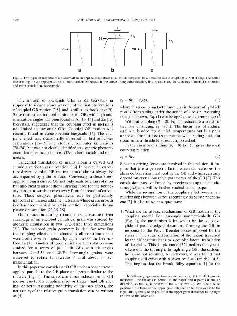
2. Relative translation of the grains parallel to the GBplane coupled to normal GB motion (Fig. 1(a) and(b)). During this process, the GB shears the material tra-versed by its motion. The coupled GB motion followsone of several possible geometric relations between vn
and the relative grain translation velocity vi [4,5].3. Relative rigid-body translation of the grains along the
GB by sliding (Fig. 1(c)). In this paper we define andidentify GB sliding by grain translation events that arenot coupled to normal GB motion.
4. Grain rotation, a process which changes the lattice mis-orientation across the GB. This process is always accom-panied by a relative grain translation along the GB.
In this paper we confine ourselves to cases in which themotions of the grains are parallel to the GB; the case inwhich the grain translation requires shape accommodationis treated elsewhere [6].
rights reserved.
GB
GBGB
v v||
v||
n
a b c
τ τ
Fig. 1. Two types of response of a planar GB to an applied shear stress s. (a) Initial bicrystal; (b) GB motion due to coupling; (c) GB sliding. The dottedline crossing the GB represents a set of inert markers embedded in the lattice or any other fiduciary line. vn and vi are the velocities of normal GB motionand grain translation, respectively.
1 The following sign convention is assumed in Eq. (1): the GB plane ishorizontal, the tilt axis is normal to the paper and n points in the updirection, so that vn is positive if the GB moves up. We take s to bepositive if the force on the upper grain relative to the lower one is to theright, and vi and vs to be positive if the upper grain translates to the rightrelative to the lower one.
4954 J.W. Cahn et al. / Acta Materialia 54 (2006) 4953–4975
The motion of low-angle GBs in Zn bicrystals inresponse to shear stresses was one of the first observationsof coupled GB motion [7,8], and is still a textbook case [9].Since then, stress-induced motion of tilt GBs with high mis-orientation angles has been found in Al [10–14] and Zn [15]bicrystals, suggesting that the coupling effect in metals isnot limited to low-angle GBs. Coupled GB motion wasrecently found in cubic zirconia bicrystals [16]. The cou-pling effect was occasionally observed in first-principlescalculations [17–19] and atomistic computer simulations[20–24], but was not clearly identified as a generic phenom-enon that must occur in most GBs in both metals and non-metals.
Tangential translation of grains along a curved GBshould give rise to grain rotation [3,6]. In particular, curva-ture-driven coupled GB motion should almost always beaccompanied by grain rotation. Conversely, a shear stressapplied along a curved GB not only leads to grain rotationbut also creates an additional driving force for the bound-ary motion towards or even away from the center of curva-ture. These coupled phenomena can be particularlyimportant in nanocrystalline materials, where grain growthis often accompanied by grain rotation, especially duringplastic deformation [23,25–28].
Grain rotation during spontaneous, curvature-drivenshrinkage of an enclosed cylindrical grain was studied byatomistic simulations in two [29,30] and three dimensions[31]. The enclosed grain geometry is ideal for revealingthe coupling effects as it eliminates all constraints thatwould otherwise be imposed by triple lines or the free sur-face. In [31], kinetics of grain shrinkage and rotation werestudied for a series of [001] tilt GBs with tilt anglesbetween h = 5.5� and 38.3�. Low-angle grains wereobserved to rotate to increase h until about h = 37�misorientation.
In this paper we consider a tilt GB under a shear stress sapplied parallel to the GB plane and perpendicular to thetilt axis (Fig. 1). The stress can either induce normal GBmotion due to the coupling effect or trigger rigid GB slid-ing, or both. Assuming additivity of the two effects, thenet rate vi of the relative grain translation can be writtenas [3]
vk ¼ bvn þ vsðsÞ; ð1Þ
where b is a coupling factor and vs(s) is the part of vi whichresults from sliding under the action of stress s. Assumingthat b is known, Eq. (1) can be applied to determine vs(s).1
Without coupling (b = 0), Eq. (1) reduces to a constitu-tive law of sliding, vi = vs(s). The linear law of sliding,vs(s) � s, is adequate at high temperatures but is a poorapproximation at low temperatures when sliding does notoccur until a threshold stress is approached.
In the absence of sliding (vs = 0) Eq. (1) gives the idealcoupling relation
vk ¼ bvn: ð2Þ
Since no driving forces are involved in this relation, it im-plies that b is a geometric factor which characterizes theshear deformation produced by the GB and which can onlydepend on crystallographic parameters of the GB [3]. Thisconclusion was confirmed by previous computer simula-tions [4,5] and will be further studied in this paper.
While the recognition of the coupling effect reveals newrelationships between various seemingly disparate phenom-ena [3], it also raises new questions:
1. What are the atomic mechanisms of GB motion in thecoupling mode? For low-angle symmetrical-tilt GBs(Fig. 2), the mechanism is known to be the collectiveglide of parallel edge dislocations, forming the GB, inresponse to the Peach–Koehler forces imposed by thestress s. The shear deformation of the region traversedby the dislocations leads to a coupled lateral translationof the grains. This simple model [32] predicts that b � h,where h is the tilt angle. In high-angle GBs the disloca-tions are not resolved. Nevertheless, it was found thatcoupling still exists with b given by b = 2tan(h/2) [4,5].This implies that the Frank–Bilby equation [1] for the

Dynamic atoms
Fixed atoms
x
y
z
v||
Grain boundary
Fig. 3. Geometry of the GB simulation block used in this work. For thefixed boundary condition the atoms in the gray slab are fixed relative toeach other and move as a rigid body. The free boundary condition isobtained by replacing all fixed atoms by dynamic atoms. vi is the velocityimposed on the upper fixed slab.
New location
Sheared region
Original location
θ
Fig. 2. The dislocation glide mechanism of coupled motion of low-anglesymmetrical tilt GBs, and the shear it produces. The solid and dashed linesshow selected atomic planes before and after the boundary displacement,respectively. The old and new boundary locations are indicated.
J.W. Cahn et al. / Acta Materialia 54 (2006) 4953–4975 4955
GB dislocation content is applicable to high angles.While simulations [4,5] show good agreement with theFrank–Bilby equation for both small and large anglesh, detailed atomistic mechanisms of coupling in high-angle GBs remain largely unknown.
2. What are the mechanisms of GB sliding? When the GBcontains dislocations that can slip in the GB plane, slid-ing can occur by dislocation glide. Twist GBs do containsuch dislocations. The dislocations in the tilt GBs stud-ied in this paper cannot slip in the GB plane and the slid-ing we observe must happen by some other mechanism.At low temperatures, GB sliding could occur by thenucleation and glide of extrinsic GB dislocations withBurgers vectors parallel to the boundary plane.
3. When and how does the mechanical response of a GBchange from coupling to sliding? Is it either couplingor sliding, or can they coexist as postulated in Eq. (1)?Coupling is found to be predominant at relatively lowtemperatures, whereas sliding is activated at high tem-peratures and large misorientations. How does the cou-pling to sliding transition depend on temperature andcrystallographic characteristics of the GB?
We attempt to answer these questions with atomisticcomputer simulations performed on planar Æ001æ symmet-rical tilt GBs in Cu over the entire range of tilt angles and awide range of temperatures. Since the GBs are symmetrical,the grains are oriented to have the same shear moduli par-allel to the boundary. Consequently, applied shear stressesdo not produce any volume driving forces. The GBs haveno curvature and periodic boundary conditions preventany grain rotation. Thus, in the absence of coupling toshear stresses the GBs can only display random walk bythermal fluctuations. We thus have ideal conditions tostudy the coupling effect. Since the bicrystal lacks twofoldsymmetry around the tilt axis, it can interact with shearstresses. Such stresses can only induce GB motion providedthis motion produces shear deformation of the bicrystal.
In Section 2, we describe our methodology, which weapply in Sections 3–7 to study GB motion at relativelylow temperatures dominated by coupling. We establishthe misorientation dependence of b and determine theatomic mechanisms of GB motion. In Section 8, weexamine the temperature effect on the GB motion and
demonstrate a crossover between coupling and sliding athigh temperatures. Our geometric theory of coupling ispresented in Sections 9 and 10. Finally, in Section 11 wesummarize our findings and outline future work.
2. Methodology
A series of [001] symmetrical tilt GBs was studied usingan embedded-atom potential fit to a large database ofexperimental and first-principles data for Cu [33]. Thepotential accurately reproduces a variety of properties ofCu, including the elastic constants, phonon frequencies,thermal expansion, the intrinsic stacking fault energy, thecoherent twin boundary energy and others.
A GB was created by constructing two separate crystalswith desired crystallographic orientations and joining themalong a plane normal to the x-direction (Fig. 3). Periodicboundary conditions were applied in the y- and z-directionsparallel to the GB plane, the z-direction being parallel tothe tilt axis. Each grain had an approximately cubic shape.Depending on the tilt angle h and the goal of a particularsimulation, the simulation block contained between(1–5) · 104 atoms. Molecular dynamics (MD) simulationswere performed in the canonical ensemble (Nose–Hooverthermostat) under a fixed volume. To include the effect ofthermal expansion, prior to MD simulations the blockwas expanded uniformly by the lattice thermal expansionfactor at the desired temperature T. The thermal expansionfactors had been determined previously by zero-pressureMonte Carlo simulations [33]. The MD integration timestep was 2 fs and the total time of an MD run was typicallya few nanoseconds.
Two types of boundary condition were imposed in thex-direction. In the fixed boundary condition [34], the grainsare sandwiched between two slabs in which the atoms arefixed in their perfect-lattice positions relative to oneanother. The fixed atoms do not participate in MD simula-tions and only serve to impose interatomic forces on neigh-boring dynamic atoms. The thickness of each fixed slab istwice the cutoff radius of atomic interactions. The fixed

Table 1Characteristics of [001] symmetrical tilt GBs in Cu studied in this work. cis the GB energy at 0 K
Boundary h (�) c(J/m2) Mode bMD bideal
R101(1010) 11.42� 0.684 Æ100æ 0.199 0.200R25(710) 16.26� 0.796 Æ100æ 0.287 0.286R37(610) 18.92� 0.837 Æ100æ 0.333 0.333R13(510) 22.62� 0.878 Æ100æ 0.402 0.400R17(410) 28.07� 0.914 Æ100æ 0.497 0.500R53(720) 31.89� 0.939 Æ100æ 0.590 0.571R5(310) 36.87� 0.905 Æ110æ �1.010 �1.000R5(210) 53.13� 0.952 Æ110æ �0.667 �0.667R17(530) 61.93� 0.856 Æ110æ �0.496 �0.500R13(320) 67.38� 0.790 Æ110æ �0.391 �0.400R37(750) 71.08� 0.732 Æ110æ �0.338 �0.333R25(430) 73.74� 0.677 Æ110æ �0.285 �0.286R41(540) 77.32� 0.595 Æ110æ �0.222 �0.222R61(650) 79.61� 0.533 Æ110æ �0.195 �0.182
bMD and bideal are values of the coupling factor b computed by MDsimulations at 800 K and predicted by the geometric model, respectively.
4956 J.W. Cahn et al. / Acta Materialia 54 (2006) 4953–4975
boundary condition restricts spontaneous translations ofthe grains. Lattice regions adjacent to the GB can stilltranslate relative to each other but such translations areaccompanied by elastic deformation of those regions. Thisboundary condition was used to apply a shear parallel tothe GB by moving all fixed atoms of the upper grain withthe same constant velocity vi, while the lower slab remainedfixed.
Most of the simulations reported here were performedunder the fixed boundary condition with vi = 1 m/s in they-direction, although some runs were made with smallervelocities down to 10�2 m/s in order to probe the strain-ratedependence of the results. This scheme is computationallyefficient because it guarantees a significant grain translationover a period of time accessible by MD. We emphasize thatthis simulation procedure implements shear deformationwith a constant rate, whereas the shear stress can vary dur-ing the simulation. While constant-stress conditions couldbe more suitable for testing the observed GB dynamicsagainst theoretical models, they make it difficult to avoid‘‘wasteful’’ runs in which no interesting events happen ifthe chosen stress level is too low.
In the free boundary condition, all atoms of the simula-tion block are made dynamic, so that the grains terminateat free surfaces. MD simulations under this boundary con-dition are ideal for studying spontaneous GB motion in thecoupled regime since the grains are able to translate againsteach other without any lateral constraints.
The stress tensor averaged over all dynamic atoms wascomputed using the standard virial expression and wasconstantly monitored during the MD simulations. TheGB position was tracked automatically using the layeredstructure factor proposed in [35]. The static structure factorjS(k)j2 averaged over atomic layers parallel to the GB planewas calculated for the wave vector k = [0, 0,4p/a] (a beingthe lattice parameter of Cu). Since the function jS(k)j2(x) isalmost constant in the grains and has a sharp minimum atthe GB, the position of the minimum can be used as a con-venient GB locator. Preliminary results of these simula-tions have been reported in [4,5].
2 Unless otherwise specified, all crystallographic indices used in thiswork are taken relative to the lattice of the upper grain.
3 In defining the sign of the Burgers vector we assume that thedislocation line vector is pointing away from the viewer and use the right-hand finish–start (RH/FS) convention [36].
3. Grain boundary structures and coupling modes
The following convention is used to describe the GBcrystallography. The tilt axis is parallel to the [001] direc-tion and normal to the viewer. A symmetrical tilt GB isobtained by taking two identical face-centered cubic (fcc)crystals aligned with the coordinate system and rotatingone of them (upper grain) around the tilt axis by h/2 coun-terclockwise and the other (lower grain) by h/2 clockwise.The GB plane is always horizontal and normal to the ini-tially common [100] direction. Due to the mirrors in thecrystal symmetry around the tilt axis, the tilt of each grainby 45� recovers the perfect crystal structure with the (11 0)plane horizontal. All distinct GB structures can beobserved within the interval 0� < h < 90�. Accordingly,
there are two different types of low-angle GBs: when h issmall and when it approaches 90� from below.
Due to the periodic boundary conditions, all GBs stud-ied here had to be coincident site lattice (CSL) boundaries[1]. Each symmetrical CSL GB is uniquely defined by theindices (h k0) of the GB plane2 and is characterized by aR value (reciprocal density of CSL sites). The ground-statestructure of each GB was determined by minimizing thetotal energy of the simulation block with respect to localdisplacements of dynamic atoms and relative rigid-bodytranslations of the fixed slabs. Table 1 summarizes crystal-lographic characteristics and 0 K energies of the bound-aries studied in this work. They cover tilt angles from11.42� to 79.61� and R values between 5 and 101.
All the GBs contain topologically identical kite-shapedstructural units always pointing to the left (Fig. 4). TheGBs only differ in the distance separating the kites andtheir positions relative to the GB plane. The relativelylow-angle R37(61 0) (h = 18.9�) GB shown in Fig. 4(a) con-tains an array of dislocations whose cores are formed bythe kite units and the Burgers vectors are b = [10 0]. Like-wise, the relatively low-angle R41(540) (h = 77.3�) GBshown in Fig. 4(d) is composed of b = �1/2[110] disloca-tions formed by the kites. The Burgers vectors of the dislo-cations were determined by the standard Burgers circuitconstruction.3 Note that the dislocations in the GBs withh approaching 0� and 90� have not only different Burgersvectors but also different signs. This can be readily seenby tracing crystal planes which are almost parallel to theGB and noting that the extra half-planes terminating atthe dislocations come from the right in Fig. 4(a) and fromthe left in Fig. 4(d).

[1 6 0]
[6 1 0]
-
[0 0 1]
[3 5 0]
[5 3 0]
[0 0 1]
-
[4 5 0]
[5 4 0]
[0 0 1]
-
a
c
d
[1 3 0]
[3 1 0]
-
[0 0 1]
b
Fig. 4. Atomic structure of selected [001] symmetrical tilt GBs in Cu at0 K. (a) R37(610) (h = 18.9�); (b) R5(310) (h = 36.9�); (c) R17(530)(h = 61.9�); (d) R41(540) (h = 77.3�). The filled and open circles representrows of atoms with positions in alternating (002) planes. The structuralunits and the GB plane are outlined. (a), (b) and (d) are flat boundaries;(c) is an example of a zigzag boundary.
4 In typical MD simulations with periodic boundary conditions theinitial shape of the simulation block is preserved by mapping atoms backinto the block if they attempt to leave it. While this scheme hascomputational advantages, it masks the deformation and motion of thegrains and is not suitable for studying GB coupling or sliding. In oursimulations the atoms are not mapped back into the initial block.
J.W. Cahn et al. / Acta Materialia 54 (2006) 4953–4975 4957
In high-angle GBs, the kites approach each other andform either flat (Fig. 4(b)) or zigzag (Fig. 4(c)) arrays.The zigzag structures are found when h > 45� and the indi-ces (hk0) of the GB plane satisfy the conditionh2 + k2 = 2R. Such boundaries are called centered [37]and for the [001] tilt family occur only if both indices h
and k are odd numbers. In such cases the GB plane is par-allel to a {110} plane of the CSL of the bicrystal. The non-centered (flat) boundaries are parallel to a {100} CSLplane and satisfy the condition h2 + k2 = R.
It has been shown [5] that the 4mm crystal symmetryaround the Æ100æ axis gives rise to two branches of the mis-orientation dependence of b. One branch, termed Æ10 0æaccording to the slip direction of GB dislocations, origi-nates from the coupled motion of low-angle GBs withh! 0 and is described by the equation
bh1 0 0i ¼ 2 tanh2
� �: ð3Þ
The other branch termed Æ110æ corresponds to coupledmotion of low-angle GBs with h! 90� and is given by
bh1 1 0i ¼ �2 tanp4� h
2
� �: ð4Þ
These equations are derived from geometric models of cou-pling which will be discussed later (Section 9). Here we onlyintroduce these equations for future references.
4. Stress-induced boundary motion at medium temperatures
Shear was applied to all GBs by shifting the fixed atomsof the upper grain to the right with a constant velocity vi.At temperatures above �500 K and up to at least 800 K,all GBs were observed to move either up or down with aconstant average velocity vn. The situation at lower andhigher temperatures can be different and will be discussedseparately (Sections 5 and 8). The stress-induced GBmotion is illustrated in Fig. 5, which shows that vn canbe either positive or negative, depending on h. Note theuniform shear deformation of the initially rectangularshape of the simulation block in the region traversed bythe GB.4 This shear is a signature of the coupled GBmotion and can be contrasted to rigid sliding along theGB in which the block would be simply cut in two halvesalong the GB plane (cf. Fig. 1). The lattice regions leftbehind the moving GBs were carefully examined for vacan-cies or any other lattice defects. No defect generation wasfound in any simulations reported in this work. It was alsofound that by reversing the direction of the grain transla-tion each GB could be moved in the opposite direction withexactly the same vn.
Fig. 6 shows typical plots of the normal GB displace-ment versus time at 800 K. The average GB velocities vn
were determined by mean-squared linear fits to such plots.Note that all GBs with h < 36.9� move up while the rest ofthe GBs move down, indicating that the coupling effect isdiscontinuous and changes sign.
Some of the GBs clearly reveal an incremental, stop-and-go, character of motion while others appear to movein a more stochastic manner at this temperature. At lowertemperatures, all GBs move by a stop-and-go mechanism,each with its own increment of the normal displacementH and the associated grain translation S. The relation ofH and S to GB structure will be discussed later (Sections9.4 and 9.5). Incremental motion of GBs has been observedexperimentally [38].

-2.0
-1.5
-1.0
-0.5
0.0
0.5
1.0
1.5
2.0
0.0 0.2 0.4 0.6 0.8 1.0
GB
disp
lace
men
t (nm
)
Time (ns)
Σ37(610) θ=18.92o
Σ13(510) θ=22.62o
Σ17(410) θ=28.07o
Σ53(720) θ=31.89o
Σ5(310) θ=36.87o
Σ5(210) θ=53.13o
Σ17(530) θ=61.93o
Σ13(320) θ=67.38o
Σ41(540) θ=77.32o
Fig. 6. GB displacement versus time during MD simulations at 800 Kunder a shear parallel to the GB plane and normal to the tilt axis. Theshear rate is 1 m/s.
-1.5
-1.0
-0.5
0.0
0.5
1.0
1.5
0 10 20 30 40 50 60 70 80 90
Cou
plin
g fa
ctor
θ (degrees)
<100> mode
<110> mode
Σ37(610)Σ13(510)
Σ17(410)Σ53(720)
Σ5(310)
Σ5(210)
Σ17(530)Σ13(320)
Σ37(750)Σ25(430)
Σ41(540)Σ61(650)
Σ101(1010)Σ25(710)
Fig. 7. The coupling factor b obtained by MD simulations at 800 K as afunction of the tilt angle h. The lines represent two branches of b predictedby the geometric model of coupling.
GB
GB
a bFig. 5. Typical snapshots of MD simulations of stress-induced motion of the (a) R17(530) (h = 61.93�) and (b) R37(610) (h = 18.92�) GBs at 800 K underthe same shear direction. The circles and crosses show projections of dynamic and fixed atoms, respectively. The initial position of the GB is shown by ahorizontal dotted line and the final position is indicated by an arrow. The shear rate is 1 m/s and the MD time is 1.2 ns. The different directions of the GBmotion point to different signs of the coupling factor b.
4958 J.W. Cahn et al. / Acta Materialia 54 (2006) 4953–4975
The coupling factor b = vi/vn was calculated from thesesimulations. The results obtained at 800 K with vi = 1 m/sare listed in Table 1 and the observed misorientationdependence of b is plotted as points in Fig. 7. The twocurves shown in this figure were calculated from Eqs. (3)and (4). All b values obtained by the MD simulations fallon these two curves. Note the sudden switch between thecurves between the R53(720) (h = 31.9�) and R5(310)(h = 36.9�) misorientations. This switch is accompaniedby a change of sign of b from b > 0 at h 6 31.9� to b < 0at h P 36.9�. Calculations of b at all temperatures between500 and 800 K and with vi between 0.01 and 1 m/s gave vir-tually identical results, confirming that b behaves as a geo-metric factor. Such agreement between the observed andgeometrically predicted b values will be called ‘‘perfect cou-pling’’. The angle at which b changes sign does not dependon temperature within the 500–800 K range as indicated inFig. 8.
Fig. 7 displays the central result of our work, which willbe discussed and interpreted in subsequent sections of thispaper: not only does the perfect coupling exist for bothlow- and high-angle GBs, but also the misorientationdependence of the coupling factor derived for low-angleGBs continues to be perfectly accurate for all high-anglemisorientations. The observation of the discontinuousbehavior of b is another important result of the simulations.
Typical shear stress behavior during the coupled GBmotion is illustrated in Fig. 9. The stress increases almostlinearly due to elastic deformation of the material until acritical value is reached at which the boundary makes arapid move to a new position a distance H away fromthe previous one. The stress drops to a value which dependson the simulation block size in the normal direction andcan be either positive or negative. This drop of stress is

0
200
400
600
800
1000
1200
1400
0 10 20 30 40 50 60 70 80 90
Tem
pera
ture
(K
)
Tilt angle (o)
<100> coupling<110> couplingCoupling/slidingSlidingDual behavior
Fig. 8. Diagram of mechanical responses to shear of [001] symmetrical tiltGBs in Cu.
-1.0
-0.5
0.0
0.5
1.0
0.0 0.2 0.4 0.6 0.8 1.0 1.2-2.0
-1.0
0.0
1.0
2.0
Str
ess
(GP
a)
GB
dis
plac
emen
t (nm
)
Time (ns)
Stress
GB displacement
Fig. 9. Time dependencies of the shear stress and GB displacement duringthe coupled motion of the R5(210) GB at 700 K with vi = 1 m/s,illustrating the stick–slip character of GB migration.
J.W. Cahn et al. / Acta Materialia 54 (2006) 4953–4975 4959
followed by a new increase until the next peak, and the pro-cess repeats. Thus, the shear stress displays a very clearstick–slip behavior which is well known in sliding friction[39,40]. As expected, the scatter in the stress peak heightsand positions increases with temperature. While the aver-age values of H and S typically remain nearly constantand are determined by the GB geometry,5 the averageheight of the stress peak decreases with increasing temper-ature or decreasing vi.
Examination of MD snapshots shows that GB self-diffu-sion took place during some of the coupling simulations atthe high end of the temperature range. As a crude estimateof the range of diffusional motion, one can compare the dif-
5 See Fig. 10 for an exception.
fusion length over the time when an atom resides within themoving GB, [Dd/vn]1/2, with interatomic distance (d is theGB width). For example, at 800 K a typical value of Ddin R5 Cu GBs calculated with the same EAM potential isabout 2.5 · 10�20 m2/s [41]. Taking one of our GB velocitiesvn � 0.01 m/s, we obtain [Dd/vn]1/2 � 1.2 · 10�9 m, which isabout four times the interatomic distance 3 · 10�10 m. Athigher temperatures the amount of GB diffusion increases.This estimate confirms that GB diffusion can occur anddoes not seem to affect perfect coupling. This is consistentwith the notion that coupling is associated with a geometri-cal correspondence between lattice sites but not necessarilybetween individual atoms.
5. Stress-induced boundary motion at low temperatures
Coupled GB motion continues to exist at low tempera-tures, where it is strongly dominated by stick–slip behaviorof the stress. Under such conditions, the frequentlyassumed linear relation between GB velocity and stress isnot an adequate approximation. Instead, we postulate thatthere is a critical value of the applied shear stress, sci,needed to activate a particular coupling mode i = Æ100æor Æ110æ. The GB does not move unless s > min(scÆ1 0 0æ,scÆ1 1 0æ).
For low-angle GBs we expect that sci satisfies therelation
sciSiðhÞ ¼ rciðhÞ; ð5Þwhere Si(h) is the Schmid factor for the dislocation slipplane and slip direction corresponding to mode i and rci(h)is the respective critical resolved shear stress. The resolved(glide) shear stress sSi(h) is proportional to the glide com-ponent of the Peach–Koehler force acting on the disloca-tions. Relation (5) expresses the postulated Schmid law,which ignores all non-glide components of the stress andpredicts that the coupling mode with the smaller ratiorci(h)/Si(h) must prevail. At low enough temperatures, rci
can be identified with the Peierls–Nabarro stress for thecollective glide of the array of parallel straight dislocations,which can be different from the Peierls–Nabarro stress ofan isolated dislocation. Note that the GB dislocations con-sidered here can have unusual Burgers vectors and glide onunusual slip planes. At higher temperatures, the disloca-tions can move by kink-pair formation and extension andthe meaning of rci becomes more complex.
For the [001] tilt GBs we have Si(h) = cosh for theÆ1 00æ mode and cos(p/2 � h) for the Æ110æ mode. Thetwo Schmid factors are equal when h = p/4. Assuming thatEq. (5) continues to hold for high-angle boundaries, andrecalling that the change of the coupling mode occurs ath < p/4 (Fig. 7), we conclude that rci for the Æ100æ modeis larger than for the Æ110æ mode in this misorientationrange. We will be examining rci in both modes in moredetail later (Section 10).
As shown in Fig. 8, as the temperature drops, the hrange of the Æ110æ mode expands and at T! 0 may cover

0 20 40 60 800.0
0.1
0.2
0.3
0.4
θ (degrees)
|S| (
nm)
<100> mode <110> mode
b
0 20 40 60 800.00
0.05
0.10
0.15
0.20
0.25
0.30
θ (degrees)
|H| (
nm)
<100> mode <110> mode
a
Flat
Flat
Zigzag
Zigzag
Fig. 11. Absolute values of the increments of (a) normal GB displacementH and (b) tangential grain translation S, during coupled motion of [001]symmetrical tilt GBs. The circles and triangles represent results ofatomistic simulations for the Æ100æ and Æ110æ modes, respectively. Thesolid lines are obtained from Eqs. (9)–(15), the dash-dotted linecorresponds to a half of the H and S values for the Æ110æ mode. Thevertical dashed line indicates the angle of switch between the couplingmodes at 500–800 K.
4960 J.W. Cahn et al. / Acta Materialia 54 (2006) 4953–4975
all angles studied, while the range of the Æ100æ mode sh-rinks to small h. There is an overlap area, which we term‘‘dual behavior’’, in which both modes are observed atthe same h. In all cases of dual behavior, the GB beginsto move in the Æ110æ mode but later switches to theÆ100æ mode and remains in it until the end of the simula-tion. This observation of spontaneous reversal of coupledGB motion shows that both coupling modes can be imple-mented in the same boundary at the same temperature.This dual behavior is only observed within a relatively nar-row (�100 K) temperature range specific to each GB. Thetime of the switch between the coupling modes depends onthe temperature, h and vi. At temperatures above the dualarea in Fig. 8, the GB makes its first movement in the Æ1 00æmode and the Æ110æ mode is never observed.
An example of dual behavior is given in Fig. 10. Theaverage slopes of the displacement–time curves in thebeginning of the run and after the reversal give b valueswhich are in good agreement with Eqs. (4) and (3), respec-tively. Thus, the reversal signifies an abrupt switch fromone branch of the ideal coupling relation b(h) to anotherat the same h. This clearly demonstrates that b is a multi-valued function of h. Note that after the initial period oftime comprising three stick–slip events the critical stressdrops and the increments H and S of the GB motionchange. The switch to the Æ100æ mode after 1.5 ns is asso-ciated with another, although smaller, decrease of the crit-ical stress. The time-dependent critical stress reflects thechange in the GB migration mechanism as well as possiblechanges in the boundary structure.
For each boundary there is a temperature below whichonly Æ1 10æ motion is observed; a switch to the Æ10 0æ modenever occurs during the simulation times available to us.This allowed us to determine bÆ1 1 0æ for all GBs studied hereby choosing low enough temperatures. The values thusobtained lie exactly on the theoretically predicted Æ11 0æbranch of b(h), given by Eq. (4), over the entire misorienta-
-1.5
-1.0
-0.5
0.0
0.5
1.0
1.5
0.0 0.5 1.0 1.5 2.0-1.5
-1.0
-0.5
0.0
0.5
1.0
1.5
Str
ess
(GP
a)
GB
dis
plac
emen
t (nm
)
Time (ns)
Stress
GB displacement
<110><100>
Fig. 10. Shear stress and GB displacement as functions of time for theR53(720) GB at 400 K. The GB switches from the Æ110æ to the Æ100æmode of coupling after 1.5 ns. The peak stress and the time intervalbetween GB displacements change after 0.7 ns.
tion range we studied. On the other hand, we were unableto observe the Æ100æ mode of coupling below a certain tem-perature which depends on h. This limited our bÆ1 0 0æ calcu-lations to relatively high temperatures and the angularrange h [ 35� (Fig. 8), where bÆ1 0 0æ was found to be inde-pendent of temperature.
Fig. 11 displays the h dependence of H and S determinedfrom MD snapshots under ideal coupling and stick–slipconditions. There is one branch for the Æ1 00æ mode andtwo branches for the Æ110æ mode. Their interpretation willbe discussed in Sections 9.4 and 9.5.
6. Spontaneous boundary motion
Some of the GBs were observed to move during the MDsimulations as a result of thermal fluctuations evenwithout applied shear. This spontaneous GB motion wasespecially extensive under the free boundary condition,

J.W. Cahn et al. / Acta Materialia 54 (2006) 4953–4975 4961
which allowed free grain translations relative to each other.Under this condition, the GB motion had the character of anearly random walk, during which some GBs could wanderfar away from their initial position, especially at hightemperatures.
The spontaneous GB motion was often found to be cou-pled to grain translations. When spontaneous GB motionwas coupled, it always occurred at temperatures wherestress-driven motion was also coupled. Fig. 12 illustratesthe strong coupling of the R17(530) GB at 800 K. This plotshows that there is a close correlation between the graintranslations (which occur in opposite directions by equalamounts) and the normal GB motion. Furthermore, byplotting the relative grain translation against the GB dis-placement, the coupling factor b was estimated and wasfound to be in good agreement with results of stress-induced simulations. Note that the random walk velocityat this temperature can be about 1 m/s, which is compatiblewith the imposed velocities in our stress-driven simulations.
In one of the runs performed at 1200 K, the R17(53 0)boundary was observed to reach one of the free surfacesand disappear on it, turning the simulation block into a sin-gle crystal. Interestingly, when this GB was about 1 nmaway from the surface, the material confined between theGB and the surface quickly turned into metastable melt,which then crystallized with the lattice orientation of theremaining grain. Other GBs were less mobile and neverapproached a surface.
The fixed boundary condition strongly suppresses thespontaneous GB motion but does not eliminate it com-pletely. In this case, the grains can only translate at theexpense of elastic deformation, which completely changesthe character of the GB motion. Instead of a random walk,the GB now moves up and down around its average posi-tion with a correlation time and amplitude that depend onthe particular GB misorientation, temperature and the sys-tem size in the normal direction.
-1.2
-1.0
-0.8
-0.6
-0.4
-0.2
0.0
0.2
0.4
0.0 0.2 0.4 0.6 0.8 1.0 1.2 1.4
Dis
plac
emen
t (nm
)
Time (ns)
Upper grain
Lower grain
GB plane
Fig. 12. Coupling during spontaneous motion of the R17(530) GB at800 K. Simulations were performed with the free boundary condition.
7. Atomic mechanisms of coupled boundary migration
In the previous sections we saw that there are two modesof coupled GB motion differing in sign of b, that there canbe a switch between them as the tilt angle is varied, andthat there can be dual behavior in which the mode changesat a given h. In this section we examine the atomic mecha-nisms of coupled GB motion and then relate the dualbehavior to their change. Before explaining them, note thatthe perfect FCC lattice viewed along [001] can be thoughtof as containing many types of structural units. Two six-member units are relevant to this discussion, which we labelas B and C as indicated in Fig. 13. The black and white cir-cles represent atomic rows with different depths of atomicpositions. The six-member kite-shaped units forming theGB structure are referred to as units A (see examples inFig. 4). Note that black and white circles alternate in unitsA and B while unit C has three adjacent circles with thesame color.
The atomic mechanisms of coupled GB motion weredetermined by examining multiple snapshots stored duringthe MD simulations along with relevant parts of atomictrajectories. Two different types of mechanisms were found,corresponding to GB motion in the Æ100æ and Æ110æmodes.
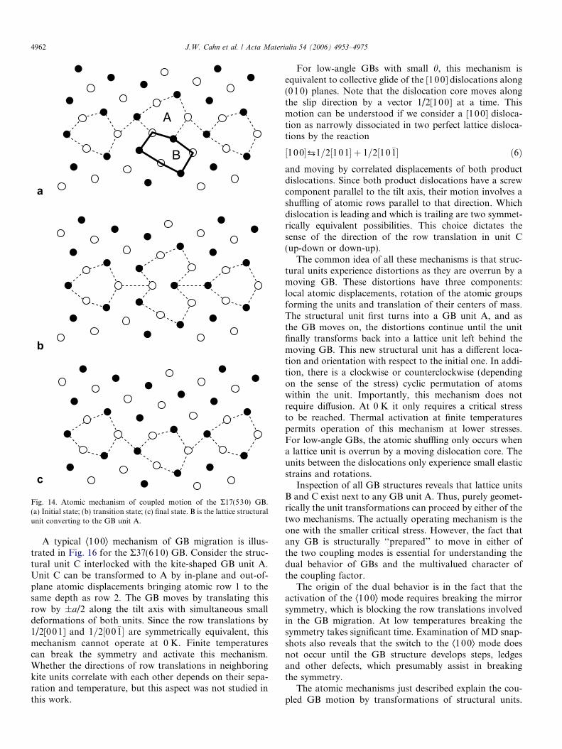
A typical Æ110æ mode mechanism is illustrated in Fig. 14using the zigzag R17(530) GB as an example. Note a struc-tural unit B adjacent to every GB unit A (Fig. 14(a)). Thetwo units can be transformed by relatively small in-planeatomic displacements, so that B becomes a kite and Abecomes a B unit in the upper grain. If this transformationhappens in every other GB unit, the boundary makes onestep down while the upper grain translates to the right inorder to accommodate the unit deformations (Fig. 14(c)).The transition state of this process is a mirror-symmetricalstructure shown in Fig. 14(b). Similar mechanisms operatein all other GBs moving in the Æ110æ mode up to some dif-ferences in relative positions of the A and B units. In GBswith a planar stacking of the A units, the A–B transforma-tions occurs in all such units simultaneously (see examplesin Fig. 15). In low-angle GBs with h approaching 90�, thismechanism represents collective glide of an array of�1/2[11 0] lattice dislocations along ð�1 10Þ planes. TheA–B transformations within the dislocation cores representelementary steps of the dislocation glide.
CB
Fig. 13. Perfect fcc lattice viewed along the [001] direction can be thoughtof as composed of structural units B or C.
a
b
c
A
B
Fig. 14. Atomic mechanism of coupled motion of the R17(530) GB.(a) Initial state; (b) transition state; (c) final state. B is the lattice structuralunit converting to the GB unit A.
4962 J.W. Cahn et al. / Acta Materialia 54 (2006) 4953–4975
A typical Æ100æ mechanism of GB migration is illus-trated in Fig. 16 for the R37(610) GB. Consider the struc-tural unit C interlocked with the kite-shaped GB unit A.Unit C can be transformed to A by in-plane and out-of-plane atomic displacements bringing atomic row 1 to thesame depth as row 2. The GB moves by translating thisrow by ±a/2 along the tilt axis with simultaneous smalldeformations of both units. Since the row translations by1/2[0 01] and 1=2½00�1� are symmetrically equivalent, thismechanism cannot operate at 0 K. Finite temperaturescan break the symmetry and activate this mechanism.Whether the directions of row translations in neighboringkite units correlate with each other depends on their sepa-ration and temperature, but this aspect was not studied inthis work.
For low-angle GBs with small h, this mechanism isequivalent to collective glide of the [100] dislocations along(01 0) planes. Note that the dislocation core moves alongthe slip direction by a vector 1/2[1 00] at a time. Thismotion can be understood if we consider a [100] disloca-tion as narrowly dissociated in two perfect lattice disloca-tions by the reaction
½10 0�¡1=2½101� þ 1=2½10�1� ð6Þand moving by correlated displacements of both productdislocations. Since both product dislocations have a screwcomponent parallel to the tilt axis, their motion involves ashuffling of atomic rows parallel to that direction. Whichdislocation is leading and which is trailing are two symmet-rically equivalent possibilities. This choice dictates thesense of the direction of the row translation in unit C(up-down or down-up).
The common idea of all these mechanisms is that struc-tural units experience distortions as they are overrun by amoving GB. These distortions have three components:local atomic displacements, rotation of the atomic groupsforming the units and translation of their centers of mass.The structural unit first turns into a GB unit A, and asthe GB moves on, the distortions continue until the unitfinally transforms back into a lattice unit left behind themoving GB. This new structural unit has a different loca-tion and orientation with respect to the initial one. In addi-tion, there is a clockwise or counterclockwise (dependingon the sense of the stress) cyclic permutation of atomswithin the unit. Importantly, this mechanism does notrequire diffusion. At 0 K it only requires a critical stressto be reached. Thermal activation at finite temperaturespermits operation of this mechanism at lower stresses.For low-angle GBs, the atomic shuffling only occurs whena lattice unit is overrun by a moving dislocation core. Theunits between the dislocations only experience small elasticstrains and rotations.
Inspection of all GB structures reveals that lattice unitsB and C exist next to any GB unit A. Thus, purely geomet-rically the unit transformations can proceed by either of thetwo mechanisms. The actually operating mechanism is theone with the smaller critical stress. However, the fact thatany GB is structurally ‘‘prepared’’ to move in either ofthe two coupling modes is essential for understanding thedual behavior of GBs and the multivalued character ofthe coupling factor.
The origin of the dual behavior is in the fact that theactivation of the Æ100æ mode requires breaking the mirrorsymmetry, which is blocking the row translations involvedin the GB migration. At low temperatures breaking thesymmetry takes significant time. Examination of MD snap-shots also reveals that the switch to the Æ100æ mode doesnot occur until the GB structure develops steps, ledgesand other defects, which presumably assist in breakingthe symmetry.
The atomic mechanisms just described explain the cou-pled GB motion by transformations of structural units.

a b
A
B
AB
B'
A'
Fig. 15. Atomic mechanisms of coupled motion of the (a) R5(210) and (b) R5(310) GBs. In both cases B is the lattice structural unit converting to the GBunit A. An alternative mechanism for the R5(310) GB could involve the units A 0 and B0, but this mechanism is never observed.
1
2
A
C
Fig. 16. Atomic mechanism of coupled motion of the R37(610) GB. C isthe lattice structural unit converting to the GB unit A. 1 and 2 are atomicrows normal to the viewer discussed in the text.
J.W. Cahn et al. / Acta Materialia 54 (2006) 4953–4975 4963
In reality, such transformations are unlikely to happensimultaneously in all units over a large GB area. MD sim-ulations reveal that GBs typically move by a nucleationand growth mechanism initiated by the formation of a rel-atively small area over which the GB has advanced(‘‘embryo’’). The ‘‘embryo’’ is separated from the rest ofthe boundary by a one-dimensional defect, which can beidentified as a GB disconnection [42–44]. Sidewise propa-gation of the disconnection loop eventually results in a nor-mal displacement of the entire boundary by one elementarystep H, accompanied by a tangential grain translation by S.Crystallographic characteristics of the disconnections willbe discussed later (Section 9.5) and their effect on GBdynamics will be the subject of a separate publication.
The formation of a critical ‘‘embryo’’ is a thermally acti-vated process, which can either occur spontaneously or bedriven by an applied shear stress. At a critical level of thestress, the nucleation activation barrier is eliminated andthe boundary migration becomes athermal. It should be
Imentioned that the disconnection loops were onlyobserved in MD simulations with large lateral dimensionsof the simulation block. In small blocks, the boundary dis-placements took place uniformly over the entire GB area.
8. Transition between coupling and sliding
So far we have only examined conditions under whichthe GB response to applied shear was perfect coupledmotion. We will now consider situations when the responsechanges, partially or completely, from coupling to slidingwith increasing temperature.
MD simulations of stress-driven GB motion were per-formed at temperatures up to �30 K below the bulk melt-ing point Tm (Tm = 1327 K) with this embedded-atompotential [41]; the experimental value for copper is1358 K. Above about 800 K the coupled GB motion beginsto be interrupted by occasional sliding events as illustratedin Fig. 17. Such events are identified as sliding because theyare accompanied by relative grain translations and a dropof stress without normal GB displacement. Between thesliding events, the GB continues to move in a coupledmode with a characteristic geometric value of b. This sug-gests that the GB sliding occurs by a mechanism that pre-serves the boundary structure. As the temperature increasesfurther, the relative frequency of the sliding eventsincreases and thus the average normal velocity vn decreases.In high-angle GBs, at high enough temperatures the cou-pled motion ceases to be observed and sliding becomesthe dominant mode of the GB response, although the GBcontinues to execute random movements over small dis-tances. Under such conditions we assign vn a zero value.
Fig. 18 shows the temperature dependence of the velocityratio vn/vi calculated for different GBs with the same shearrate vi = 1 m/s. The tilt angle increases monotonically from

-0.5
0.0
0.5
1.0
1.5
2.0
2.5
3.0
3.5
4.0
0.0 0.2 0.4 0.6 0.8 1.0
GB
dis
plac
emen
t (nm
)
Time (ns)
β = 2/5
700K800K1000K1100K1200K
-2.0
-1.5
-1.0
-0.5
0.0
0.5
0.0 0.2 0.4 0.6 0.8 1.0
GB
dis
plac
emen
t (nm
)
Time (ns)
β = -1/2
800K900K1000K1100K1200K1300K
a bFig. 17. Displacements of the (a) R13(510) and (b) R17(530) GBs as functions of time at selected temperatures. The imposed shear rate is 1 m/s. Thearrows indicate nearly horizontal regions corresponding to individual sliding events.
-5.0
-4.0
-3.0
-2.0
-1.0
0.0
1.0
2.0
3.0
4.0
700 800 900 1000 1100 1200 1300
Vel
ocity
rat
io, v
n/v
||
T (K)
16.26o
18.92o
22.62o
28.07o
31.89o
36.87o
53.13o
61.93o
71.08o
73.74o
77.32o Tm
Fig. 18. Temperature dependence of the velocity ratio vn/vi obtained byMD simulations with the shear rate vi = 1 m/s. Open symbols indicatetemperatures at which GB sliding events were observed. Tm is the bulkmelting temperature.
4964 J.W. Cahn et al. / Acta Materialia 54 (2006) 4953–4975
the upper curves to the lower ones. At relatively low temper-atures vn/vi remains practically constant and matches thegeometric value of 1/b, which confirms that the couplingis perfect. For high-angle GBs there is a temperature, whichwe refer to as the crossover temperature, at which jvn/vijbegins to decrease due to random switches between cou-pling and sliding. The scatter of vn/vi values in the crossoverregime is due to the limited statistics collected under condi-
tions when only a few sliding events could happen during anMD run. Above the crossover temperature range, slidingdominates over coupling. These data can be mapped ontothe diagram of mechanical responses, Fig. 8, creating adomain of sliding separated from the coupling domainsby relatively narrow crossover regions.
To check whether the crossover from coupling to slidingis sensitive to vi, the calculations for the R5(210) GB wererepeated with a shear rate of 0.5 m/s. The temperaturedependence of vn/vi obtained, and thus the crossover tem-perature, were found to be nearly the same as forvi = 1 m/s. This observation only indicates that the resultsshown in Fig. 18 are not extremely sensitive to vi; we can-not, however, exclude their shear-rate dependence undermuch greater variations in vi.
The observation of the crossover regime indicates thatcoupling and sliding can coexist in the same GB, which val-idates our postulated Eq. (1). Furthermore, because b(h) isknown from both theory and low-temperature simulations,we are in a position to evaluate the sliding component vs ofthe grain translation velocity by rearranging Eq. (1):
vs ¼ vk � bðhÞvn: ð7Þ
Since vi is imposed and vn is measured by the simulations,the right-hand side of this equation is known and we candeduce vs. We can also introduce the quantity
f � vs
vk¼ 1� bvn
vk; ð8Þ
which characterizes the fraction of vi associated with slid-ing events. (Note that b has the same sign as the ratiovn/vi, so that bvn/vi is always positive.)
Fig. 19 displays the temperature dependencies of f forvarious GBs. As expected, high-angle GBs show a rapidincrease in f in the crossover temperature range and eventu-ally reach the condition f � 1 (pure sliding). For low-angle

0.0
0.2
0.4
0.6
0.8
1.0
700 800 900 1000 1100 1200 1300
Fra
ctio
n of
slid
ing,
ζ
T (K)
Σ25(710)Σ37(610)Σ13(510)Σ17(410)Σ53(720)Σ5(310)Σ5(210)Σ17(530)Σ37(750)Σ25(430)Σ41(540)
Fig. 19. The fraction of sliding as a function of temperature for selectedGBs. The GBs are listed in increasing tilt angle.
J.W. Cahn et al. / Acta Materialia 54 (2006) 4953–4975 4965
GBs, f remains practically zero until the melting point.Using the criterion f = 0.5 as a definition we can quantifythe crossover temperature. If this condition is never satis-fied, we identify the crossover temperature with Tm for thisdiscussion. Fig. 20 shows that this crossover temperaturereaches a minimum of about 0.7Tm in the high-angle region,where b changes sign. Although these estimates of the cross-over temperatures relative to Tm are obtained for Cu, weexpect them to be valid for other metals as well.
We expect that the critical stresses for coupling and slid-ing for the same h are different, and that both are temper-ature-dependent. The coupling to sliding transition can beexplained by a crossover of the respective critical stresses.Note that the temperature range of the crossover regimeis wider when it occurs a lower temperatures. This is con-trary to what one would expect for Arrhenius behaviorof two competing reactions with different but tempera-ture-independent barriers. In our case, however, the barri-ers and the critical stresses do vary with temperature.
0.5
0.6
0.7
0.8
0.9
1.0
0 10 20 30 40 50 60 70 80 90
Cro
ssov
er te
mpe
ratu
re /
T m
θ (degrees)
<100>-mode<110>-mode
Fig. 20. The coupling-to-sliding crossover temperature, normalized by themelting temperature Tm, as a function of the tilt angle h. The couplingmodes of the GBs are indicated.
To put these observations in a different perspective,choose a temperature, e.g., 0.85Tm (�1100 K for Cu), forwhich sliding dominates at high tilt angles. Suppose wevary the tilt angle of a planar boundary gradually from 0to 90� under a fixed vi. The diagram of mechanicalresponses, Fig. 8, predicts that the boundary will initiallybe moving with perfect coupling in the small-angle Æ100æmode (b � h > 0). As h increases, individual sliding eventswill begin to happen, which will reduce the average vn. Atsome point the GB response will switch completely fromcoupling to sliding and the GB will stop moving, althoughsmall random displacements may still be observed. At lar-ger angles, coupling events will begin to be seen, but nowthey will be driving the GB in the opposite direction(Æ110æ mode, b < 0). Finally, with h approaching 90� wewill arrive at a low-angle GB moving with a perfect cou-pling factor b � h � p/2 < 0.
A similar situation may have been realized during thesimulations of the shrinkage and rotation of an enclosedcylindrical grain when the temperature was about 2/3 ofthe melting point of the Lennard-Jones solid [31]. This tem-perature is large enough to give rise to sliding in high-angleGBs, which may explain the observed gradual reduction inthe rotation velocity at large tilt angles relative to its idealvalue bvn.
9. Geometric models of coupling
9.1. General considerations
The goal of this section is to relate the coupling factor band the increments H and S of GB motion to crystallo-graphic characteristics of symmetrical tilt GBs. We willalso show how the multiplicity of possible geometricdescriptions of the same GB, arising from point symmetryof the crystal lattice, leads to the multivalued character ofb, H and S.
As a GB moves, it produces a rotation of the lattice ofthe receding grain into the orientation of the growing grain.The essence of the coupling effect is that this lattice reorien-tation is accompanied by a specific shape deformation ofthe material. If we label atoms residing within a relativelylarge (‘‘macroscopic’’) material region in front of the mov-ing GB, the shape of this region will be altered by the pas-sage of the GB. In the case of ideal coupling, the shapechange of any such region can be described by a uniquedeformation tensor, D, which depends on crystallographiccharacteristics of the GB. For a planar tilt GB, the shapedeformation D is a simple shear parallel to the GB charac-terized by a coupling factor b, with the GB plane being theinvariant plane of the shear.6 Any other type of deforma-tion would produce a long-range elastic strain field in thegrains.
6 For a boundary with a twist component, D can also include a rotationaround the boundary normal.
Final GB
Initial GB
B
O
C B
A
O
C
B'
A'
A
O A'
B'C C'
θ
θ/2
ψ
a
b
c
L
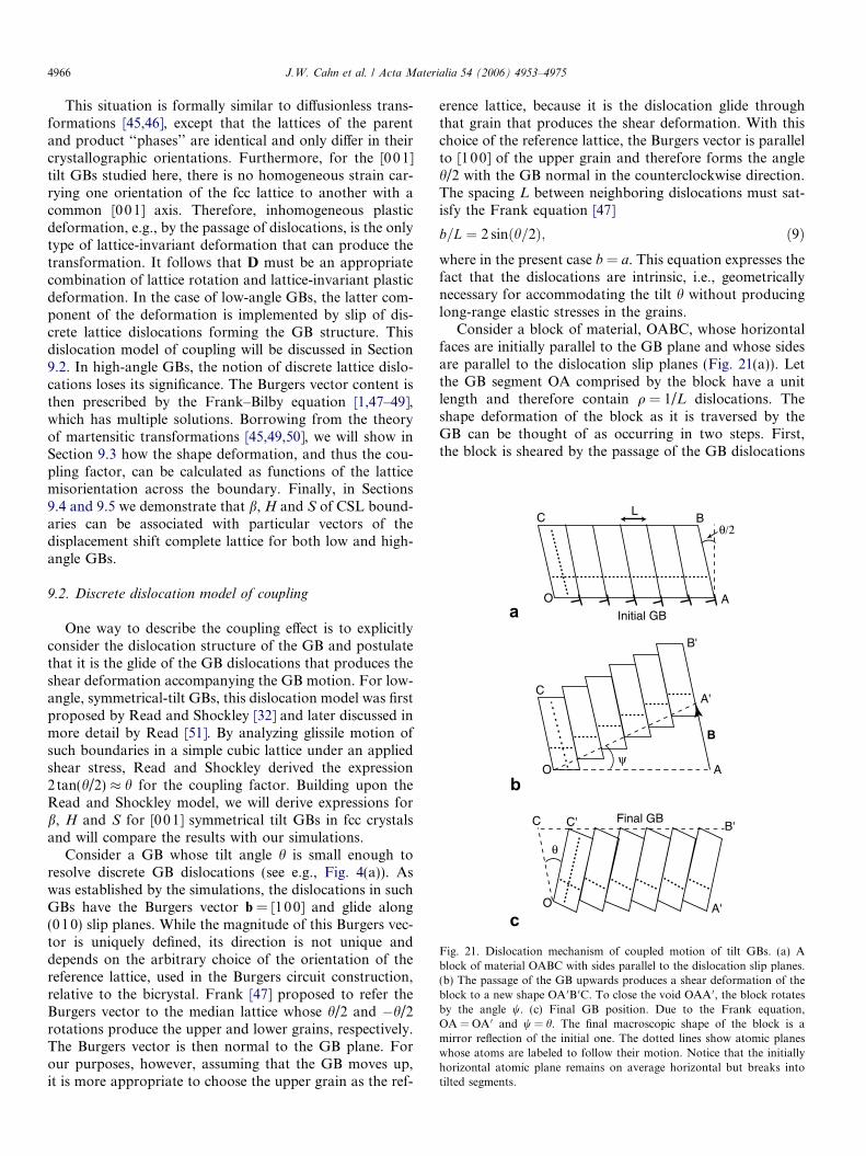
Fig. 21. Dislocation mechanism of coupled motion of tilt GBs. (a) Ablock of material OABC with sides parallel to the dislocation slip planes.(b) The passage of the GB upwards produces a shear deformation of theblock to a new shape OA 0B 0C. To close the void OAA 0, the block rotatesby the angle w. (c) Final GB position. Due to the Frank equation,OA = OA 0 and w = h. The final macroscopic shape of the block is amirror reflection of the initial one. The dotted lines show atomic planeswhose atoms are labeled to follow their motion. Notice that the initiallyhorizontal atomic plane remains on average horizontal but breaks intotilted segments.
4966 J.W. Cahn et al. / Acta Materialia 54 (2006) 4953–4975
This situation is formally similar to diffusionless trans-formations [45,46], except that the lattices of the parentand product ‘‘phases’’ are identical and only differ in theircrystallographic orientations. Furthermore, for the [00 1]tilt GBs studied here, there is no homogeneous strain car-rying one orientation of the fcc lattice to another with acommon [001] axis. Therefore, inhomogeneous plasticdeformation, e.g., by the passage of dislocations, is the onlytype of lattice-invariant deformation that can produce thetransformation. It follows that D must be an appropriatecombination of lattice rotation and lattice-invariant plasticdeformation. In the case of low-angle GBs, the latter com-ponent of the deformation is implemented by slip of dis-crete lattice dislocations forming the GB structure. Thisdislocation model of coupling will be discussed in Section9.2. In high-angle GBs, the notion of discrete lattice dislo-cations loses its significance. The Burgers vector content isthen prescribed by the Frank–Bilby equation [1,47–49],which has multiple solutions. Borrowing from the theoryof martensitic transformations [45,49,50], we will show inSection 9.3 how the shape deformation, and thus the cou-pling factor, can be calculated as functions of the latticemisorientation across the boundary. Finally, in Sections9.4 and 9.5 we demonstrate that b, H and S of CSL bound-aries can be associated with particular vectors of thedisplacement shift complete lattice for both low and high-angle GBs.
9.2. Discrete dislocation model of coupling
One way to describe the coupling effect is to explicitlyconsider the dislocation structure of the GB and postulatethat it is the glide of the GB dislocations that produces theshear deformation accompanying the GB motion. For low-angle, symmetrical-tilt GBs, this dislocation model was firstproposed by Read and Shockley [32] and later discussed inmore detail by Read [51]. By analyzing glissile motion ofsuch boundaries in a simple cubic lattice under an appliedshear stress, Read and Shockley derived the expression2tan(h/2) � h for the coupling factor. Building upon theRead and Shockley model, we will derive expressions forb, H and S for [00 1] symmetrical tilt GBs in fcc crystalsand will compare the results with our simulations.
Consider a GB whose tilt angle h is small enough toresolve discrete GB dislocations (see e.g., Fig. 4(a)). Aswas established by the simulations, the dislocations in suchGBs have the Burgers vector b = [100] and glide along(010) slip planes. While the magnitude of this Burgers vec-tor is uniquely defined, its direction is not unique anddepends on the arbitrary choice of the orientation of thereference lattice, used in the Burgers circuit construction,relative to the bicrystal. Frank [47] proposed to refer theBurgers vector to the median lattice whose h/2 and �h/2rotations produce the upper and lower grains, respectively.The Burgers vector is then normal to the GB plane. Forour purposes, however, assuming that the GB moves up,it is more appropriate to choose the upper grain as the ref-
erence lattice, because it is the dislocation glide throughthat grain that produces the shear deformation. With thischoice of the reference lattice, the Burgers vector is parallelto [100] of the upper grain and therefore forms the angleh/2 with the GB normal in the counterclockwise direction.The spacing L between neighboring dislocations must sat-isfy the Frank equation [47]
b=L ¼ 2 sinðh=2Þ; ð9Þwhere in the present case b = a. This equation expresses thefact that the dislocations are intrinsic, i.e., geometricallynecessary for accommodating the tilt h without producinglong-range elastic stresses in the grains.
Consider a block of material, OABC, whose horizontalfaces are initially parallel to the GB plane and whose sidesare parallel to the dislocation slip planes (Fig. 21(a)). Letthe GB segment OA comprised by the block have a unitlength and therefore contain q = 1/L dislocations. Theshape deformation of the block as it is traversed by theGB can be thought of as occurring in two steps. First,the block is sheared by the passage of the GB dislocations

J.W. Cahn et al. / Acta Materialia 54 (2006) 4953–4975 4967
without changing its lattice orientation. Assuming thatpoint O is fixed, the block experiences the plastic deforma-tion shown in Fig. 21(b). Side AB undergoes a parallel dis-placement by the total Burgers vector of the dislocations,B = qb, while the segment OA rotates by an angle w to anew position OA 0.
At the second step, the block rotates clockwise by the tiltangle h to align the lattice within the block with the latticeof the lower grain. This rotation aligns [100] directions ofboth grains parallel to each other. To maintain the contigu-ity of the material, this rotation must close the void OAA 0
existing at the GB. This void does close perfectly since, byEq. (9), the length of the side OA is conserved and w = h. Ifthe sides OA and OA 0 were different, a tensile strain wouldbe required to close the void and the GB motion wouldproduce a long-range elastic strain field. As mentionedabove, the Frank equation (9) guarantees that such fieldsdo not arise.
In reality, the shear and rotation steps occur simulta-neously. The resulting shape change of the block representsa simple shear parallel to the GB plane (Fig. 21(c)). It fol-lows that the angles formed by the sides OC and AB withthe GB normal before and after the deformation are h/2and �h/2, respectively. From the symmetry of the triangleOCC 0 we immediately obtain the coupling factor
bh1 0 0i ¼ 2 tanðh=2Þ: ð10Þ
This factor is positive by our sign convention and repre-sents the Æ1 00æ mode of coupling.
The [100] dislocations advance along the slip directionby increments of a/2 (Fig. 16). Therefore, each step ofthe GB motion is accompanied by a normal displacement
H h1 0 0i ¼ ða=2Þ cosðh=2Þ ð11Þ
and a tangential translation of the upper grain to the rightby
Sh1 0 0i ¼ a sinðh=2Þ: ð12Þ
These relations are readily derived from the triangle OCC 0
assuming OC = OC 0 = a/2.As indicated in Fig. 21, the shear deformation produced
by the dislocations is inhomogeneous. Atomic layers paral-lel to the dislocation slip planes rotate by the angle h butotherwise remain undistorted. By contrast, layers parallelto the GB plane break into segments confined betweenneighboring slip planes and each segment rotates by theangle h individually. In fact, all atomic layers that are notparallel to the slip planes break into segments. This seg-mentation is caused by the inhomogeneous atomic move-ments (‘‘shuffling’’) at the slip planes during thedislocation glide. The segmentation of atomic planes wasverified in the atomistic simulations by labeling atomsresiding in particular planes and plotting their new posi-tions after they were swept by a moving GB.
Despite the segmentation, any layer of labeled atomswhich is initially parallel to the GB plane remains on aver-age parallel to it after the deformation. This is consistent
with the notion that the shape deformation is a macro-scopic property defined by averaging over atomic-leveldetails. It is only on this macroscopic scale that the defor-mation produced by the GB represents pure shear and thatthe GB plane is the invariant plane of this shear.
This model is readily extended to GBs with h approach-ing 90�. In this case, the GB dislocations have the Burgersvector b = �1/2[1 10] (e.g., Fig. 4(d)) and glide along ð�110Þplanes. A schematic illustrating the shear deformation pro-duced by these dislocations is not shown here but can beobtained by a 180� rotation of Fig. 21 around the axis nor-mal to the viewer, with a replacement of h by u = 90� � h.The Frank equation now becomes
b=L ¼ 2 sinðu=2Þ; ð13Þwhere b ¼ a=
ffiffiffi2p
. As the GB moves down, the block OABCexperiences a shear deformation parallel to the GB plane,accompanied by a translation of the lower grain to the left.In this process, the ½1�1 0� direction of the lower grain ro-tates clockwise by the angle u and becomes parallel tothe [110] direction of the upper grain. Since the two direc-tions are equivalent by cubic symmetry, the lattice remainscontinuous across the GB plane.
Assuming that the dislocations move by increments of b
and repeating the preceding calculations, we obtain theincrements of normal GB motion and grain translation
H h1 1 0i ¼ �ða=ffiffiffi2pÞ cosðu=2Þ; ð14Þ
Sh1 1 0i ¼ affiffiffi2p
sinðu=2Þ: ð15Þ
Their ratio b = S/H gives the expression for the couplingfactor,
bh1 1 0i ¼ �2 tanðu=2Þ ð16Þcorresponding to the Æ110æ mode of coupling. Note thatb < 0.
This model has been verified by the MD simulations(Section 4). The coupling factors obtained perfectly followEq. (10) when h is small and Eq. (16) when it approaches90� (Fig. 7). More importantly, both equations continueto work perfectly well beyond the low-angle misorienta-tions, suggesting that these equations have a more generalmeaning. This meaning will be discussed below.
9.3. Extended model of coupling
The discrete dislocation model discussed in the previoussection essentially rests on the Frank equation, which relatesthe intrinsic Burgers vector density to the lattice misorienta-tion across a low-angle GB. The Frank equation remainsvalid for high-angle GBs in a generalized form proposedby Bilby [48,49] in the context of his continuously dislocatedcrystal theory. In that theory, Eqs. (9) and (13) representdefinitions of the intrinsic dislocation content which is for-mally assigned to a GB in order to accommodate the misori-entation between the grains without producing long-rangestresses. For a general GB, this formal dislocation contentis characterized by a ‘‘surface dislocation density tensor’’

GB
g
p
m
r
Sru
Dr - r
O
B Dr
n
R
Fig. 22. The shape deformation D produced by a moving GB as acombination of shear S and rotation R, showing that Dr � r is parallel tothe GB. r is any macroscopic vector scribed in the upper grain.
4968 J.W. Cahn et al. / Acta Materialia 54 (2006) 4953–4975
and the entire GB is treated as one entity called a ‘‘surfacedislocation’’ [48,49].
For a pure tilt GB, the surface dislocation density tensorcan be replaced by a vector quantity B, which representsthe total Burgers vector of all formal dislocations crossinga unit vector bp which lies in the GB plane and is normal tothe tilt axis. If Ru and Rl are matrices of rotation of theupper and lower grains relative to a chosen reference lat-tice, the Frank–Bilby equation defining B reads7
B ¼ ðR�1l � R�1
u Þbp: ð17ÞA major problem associated with applications of this equa-tion is the non-uniqueness of the dislocation content as-signed to a GB. Indeed, point symmetry operationsapplied to the lattice of either grain can alter the rotationsRl or Ru, and thus B, without changing the actual GBstructure or energy.
As before, if the GB moves upwards, we choose theupper grain as the reference lattice. The lower grain is thenobtained by a rotation R ¼ RuRlR
�1u of the upper grain and
Eq. (17) takes the form
B ¼ ðR�1 � IÞbp; ð18Þwhere I is the identity matrix. Applying the rotation R toboth sides of this equation, we obtain a useful relation
RB ¼ bp � Rbp: ð19ÞRepresent B as Bbg, where bg is a unit vector parallel to B.We postulate that the ‘‘surface dislocation’’ is capable ofgliding along the plane containing B and the tilt axis(Fig. 22). Let bm be the unit normal to this plane, so thatbm � bg ¼ 0. Following Bullough and Bilby [50], we assumethat the material swept by the ‘‘surface dislocation’’ under-goes a shape change D = RS consisting of two compo-nents: (i) plastic deformation S performed withoutaltering the lattice orientation, and (ii) lattice rotation byR. (A third component considered in [50] is a homogeneouslattice strain, which is absent in our case.) The role of therotation is to align the lattice traversed by the GB parallelto the lattice of the lower grain. The role of the plasticdeformation is to accommodate the shape change of thematerial and eliminate any long-range stresses.
To calculate S, consider a macroscopic vector r scribedin the upper grain and crossing the boundary at point O.Resolving it along bg and bp we have r ¼ xbg þ ybp, wherex ¼ ðr � bnÞ=ðbg � bnÞ and y ¼ ðr � bmÞ=ðbg � bnÞ.8 We postulatethat under the transformation S the tip of r experiences adisplacement u equal to the net Burgers vector, yB, of alldislocations crossed by the parallel component ybp. Thus,
7 In Bilby’s original theory [48,49] the matrices Ru and Rl representarbitrary lattice transformations which may include not only rotations butalso homogeneous lattice strains. This general form of the theory appliesto both GBs and interphase interfaces. For the present discussion we limitthe transformation matrices to lattice rotations around the tilt axis.
8 The component of r parallel to the tilt axis is invariant under alltransformations and can be safely disregarded.
u ¼ yB ¼ bðr � bmÞbg; ð20Þwhere we introduced
b � Bbg � bn : ð21Þ
Eq. (20) defines S through the relation Sr ¼ rþ u ¼ðxþ yBÞbg þ ybp. It shows that S is a simple shear by b inthe direction bg parallel to the slip plane bm. Note that forany r lying in the plane bm, Eq. (20) gives u = 0, showingthat bm is an invariant plane of this shear.
The total shape deformation D is now obtained byapplying the rotation R to the deformed vector Sr
Dr ¼ RSr ¼ ðxþ yBÞRbg þ yRbp; ð22Þwhich after some manipulation using Eq. (19) becomes
Dr ¼ rþ ðRbg � bgÞ r � bnbg � bn : ð23Þ
It can be shown (see Appendix) that Rbg � bg ¼ Bbp, whichallows us to rewrite Eq. (23) as
Dr ¼ rþ bðr � bnÞbp ð24Þwith b given by Eq. (21). This relation shows that the shapedeformation produced by the moving boundary is indeedsimple shear by b parallel to the GB plane and normal tothe tilt axis. The GB plane is an invariant plane of theshear, since for any r lying in the GB plane we haver � bn ¼ 0 and Eq. (24) gives Dr = r.
Eq. (21) predicts coupling factors for both low- andhigh-angle misorientations. As mentioned above, b and B
are not unique due to the point symmetry of the crystal.For example, we can choose R as a clockwise rotation bythe smallest possible angle h. Then the Frank–Bilby equa-tion (18) dictates that B has the magnitude B = 2sin(h/2)and forms the angle h/2 counterclockwise with respect tobn. This makes B parallel to the [100] direction of the uppergrain, so that the ‘‘surface dislocation’’ glides along (010)planes. We then have bg � bn ¼ cosðh=2Þ and Eq. (21) givesb = 2 tan(h/2), an expression which was previously derivedfor the Æ100æ mode of coupling within the discrete disloca-tion model.
On the other hand, this rotation R can be combined witha counterclockwise 90� rotation of the lattice of the lower

J.W. Cahn et al. / Acta Materialia 54 (2006) 4953–4975 4969
grain around [001], which is a point-symmetry operationthat cannot affect the GB structure. With this new choiceof R, B becomes parallel to the ½�1�10� direction of the uppergrain and has the magnitude B = 2sin(u/2), whereu = 90� � h. The ‘‘surface dislocation’’ now glides alongð�110Þ planes, which corresponds to the Æ110æ mode of cou-pling. Considering that bg � bn ¼ � cosðu=2Þ, Eq. (21) yieldsb = �2tan(u/2), which is the familiar Æ110æ mode expres-sion derived earlier within the discrete dislocation model.Thus, the shift of the rotation angle h by 90� gives rise toa new mode of GB motion, in which the lattice of the reced-ing grain rotates by the angle h � 90� instead of h. For-mally, two more branches of b(h) could be obtained byshifting h by �180� and �270�, but they are unlikely tobe realized in experiments or simulations since they requirelarger lattice rotations than the previous two.
Thus, using the concept of a ‘‘surface dislocation’’ andthe formal analogy with martensitic transformations, wehave extended the discrete dislocation model of couplingto high-angle GBs. In the limiting cases of low-angle GBsarising at the ends of the misorientation range, we correctlyrecover the expressions for b(h) obtained within the dis-crete dislocation model. The extended model therefore pre-dicts that those expressions continue to be valid across theentire misorientation range, which was indeed verified byatomistic simulations (Fig. 7). This analysis also demon-strates that the multivalued character of b originates fromthe invariance of the GB structure under point symmetryoperations in the grains.
Another important feature of the extended model is thatit does not require that the GB be symmetrical. The modelpredicts that the coupling factor only depends on the tiltangle but not on the GB plane inclination. We are in theprocess of testing this prediction by atomistic simulations.A low-angle asymmetrical tilt GB of the [001] family con-tains a mixed array of Æ10 0æ and 1/2Æ110æ dislocations. It isnot immediately clear how the dislocations having differentBurgers vectors and gliding along intersecting slip planescan conspire to move together and maintain the same GBstructure without locking each other. Besides dislocationglide, this motion may involve other processes such ascross-slip and dissociation–recombination reactionsbetween the dislocations. Read and Shockley [32,51] sug-gested that glissile motion of asymmetrical GBs would beimpossible, but no convincing proof of this conjecturewas presented.
9.4. Increments of boundary motion
The dislocation model discussed in Section 9.2 also pre-dicts the multiplicity of the increments, H and S, of thecoupled GB motion. Fig. 11 displays the misorientationdependencies of H and S calculated from the dislocationmodel and compared with results of atomistic simulations.Two interesting features are revealed by this plot.
Firstly, excellent agreement is observed between predic-tions of the dislocation model and MD results for both
coupling modes, not only for low-angle GBs but acrossthe entire misorientation range. We again observe thatthe dislocation model proposed for low-angle GBs contin-ues to work for high-angle misorientations, despite the factthat individual dislocations can no longer be resolved.
Secondly, while H and S obtained for flat GBs perfectlyagree with Eqs. (14) and (15), the values for zigzag GBs areexactly half of those predictions and thus fall on a separatecurve. This indicates that zigzag GBs actually move byincrements of b/2 and not b as was assumed in derivingEqs. (14) and (15). As a result, the Æ110æ branches ofH(h) and S(h) split in two sub-branches corresponding toflat and zigzag GBs. The only exception is the R5(310)GB, which has a planar structure but still lies on the zigzagsub-branch. We emphasize that both sub-branches arecharacterized by the same coupling factor b(h).
The origin of this difference between the flat and zigzagGBs can be understood from the atomic mechanisms oftheir motion. A zigzag GB structure can be considered asbeing split into two layers formed by the structural units,as illustrated in Fig. 14. Such boundaries always move inthe Æ110æ mode by translating one layer of structural unitsat a time. Although the layer moves by the full Burgers vec-tor b, the GB plane (which can be identified as a medianplane between the two layers) only translates by b/2. Bycontrast, during the Æ110æ motion of flat GBs all structuralunits translate by b simultaneously (see example inFig. 15(a)).
The R5(310) GB presents a special case. By analogywith other flat GBs one could expected it to move by A 0–B 0 unit transformations as indicated in Fig. 15(b). Thiswould lead to H and S values consistent with Eqs. (14)and (15). However, the actual motion of this GB involvesthe lattice unit B situated one (310) layer closer to theGB plane, resulting in H and S which are twice as small.
It is interesting to note that all boundaries lying on thelower sub-branch (dash-dotted line in Fig. 11) belong tothe class of centered GBs [37] with h2 + k2 = 2R (both hand k are odd), whereas the higher sub-branch is populatedby non-centered GBs (h2 + k2 = R). Because in any smallvicinity of a centered misorientation there are non-centeredones and vise versa, the functions H(h) and S(h) corre-sponding to the Æ110æ mode of coupling are not only mul-tivalued but also non-analytical.
9.5. Disconnections at grain boundaries
As discussed in Section 7, the motion of a planar GBunder an applied shear stress is unlikely to happen uni-formly over a large area. Rather, an area of a criticalnucleus size should first undergo a normal displacementand expand by spreading sidewise in a manner similar tothe nucleation and growth of a new ‘‘phase’’. The shearstress provides the driving force of this process and playsa role similar to the undercooling in a first-order phasetransformation. The critical nucleation size is dictated bya balance between the elastic strain energy released due
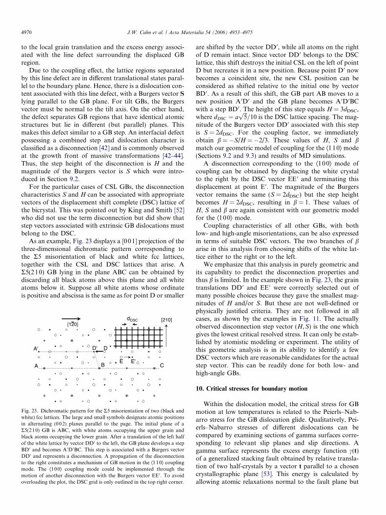
4970 J.W. Cahn et al. / Acta Materialia 54 (2006) 4953–4975
to the local grain translation and the excess energy associ-ated with the line defect surrounding the displaced GBregion.
Due to the coupling effect, the lattice regions separatedby this line defect are in different translational states paral-lel to the boundary plane. Hence, there is a dislocation con-tent associated with this line defect, with a Burgers vector S
lying parallel to the GB plane. For tilt GBs, the Burgersvector must be normal to the tilt axis. On the other hand,the defect separates GB regions that have identical atomicstructures but lie in different (but parallel) planes. Thismakes this defect similar to a GB step. An interfacial defectpossessing a combined step and dislocation character isclassified as a disconnection [42] and is commonly observedat the growth front of massive transformations [42–44].Thus, the step height of the disconnection is H and themagnitude of the Burgers vector is S which were intro-duced in Section 9.2.
For the particular cases of CSL GBs, the disconnectioncharacteristics S and H can be associated with appropriatevectors of the displacement shift complete (DSC) lattice ofthe bicrystal. This was pointed out by King and Smith [52]who did not use the term disconnection but did show thatstep vectors associated with extrinsic GB dislocations mustbelong to the DSC.
As an example, Fig. 23 displays a [001] projection of thethree-dimensional dichromatic pattern corresponding tothe R5 misorientation of black and white fcc lattices,together with the CSL and DSC lattices that arise. AR5(210) GB lying in the plane ABC can be obtained bydiscarding all black atoms above this plane and all whiteatoms below it. Suppose all white atoms whose ordinateis positive and abscissa is the same as for point D or smaller
A B
A' D' D
E E'C
dDSC [210][120]
Fig. 23. Dichromatic pattern for the R5 misorientation of two (black andwhite) fcc lattices. The large and small symbols designate atomic positionsin alternating (002) planes parallel to the page. The initial plane of aR5(210) GB is ABC, with white atoms occupying the upper grain andblack atoms occupying the lower grain. After a translation of the left halfof the white lattice by vector DD 0 to the left, the GB plane develops a stepBD 0 and becomes A 0D 0BC. This step is associated with a Burgers vectorDD 0 and represents a disconnection. A propagation of the disconnectionto the right constitutes a mechanism of GB motion in the Æ110æ couplingmode. The Æ100æ coupling mode could be implemented through themotion of another disconnection with the Burgers vector EE 0. To avoidoverloading the plot, the DSC grid is only outlined in the top right corner.
are shifted by the vector DD 0, while all atoms on the rightof D remain intact. Since vector DD 0 belongs to the DSClattice, this shift destroys the initial CSL on the left of pointD but recreates it in a new position. Because point D 0 nowbecomes a coincident site, the new CSL position can beconsidered as shifted relative to the initial one by vectorBD 0. As a result of this shift, the GB part AB moves to anew position A 0D 0 and the GB plane becomes A 0D 0BCwith a step BD 0. The height of this step equals H = 3dDSC,where dDSC ¼ a
ffiffiffi5p
=10 is the DSC lattice spacing. The mag-nitude of the Burgers vector DD 0 associated with this stepis S = 2dDSC. For the coupling factor, we immediatelyobtain b = �S/H = �2/3. These values of H, S and bmatch our geometric model of coupling for the Æ1 10æ mode(Sections 9.2 and 9.3) and results of MD simulations.
A disconnection corresponding to the Æ100æ mode ofcoupling can be obtained by displacing the white crystalto the right by the DSC vector EE 0 and terminating thisdisplacement at point E 0. The magnitude of the Burgersvector remains the same (S = 2dDSC) but the step heightbecomes H = 2dDSC, resulting in b = 1. These values ofH, S and b are again consistent with our geometric modelfor the Æ100æ mode.
Coupling characteristics of all other GBs, with bothlow- and high-angle misorientations, can be also expressedin terms of suitable DSC vectors. The two branches of barise in this analysis from choosing shifts of the white lat-tice either to the right or to the left.
We emphasize that this analysis in purely geometric andits capability to predict the disconnection properties andthus b is limited. In the example shown in Fig. 23, the graintranslations DD 0 and EE 0 were correctly selected out ofmany possible choices because they gave the smallest mag-nitudes of H and/or S. But these are not well-defined orphysically justified criteria. They are not followed in allcases, as shown by the examples in Fig. 11. The actuallyobserved disconnection step vector (H,S) is the one whichgives the lowest critical resolved stress. It can only be estab-lished by atomistic modeling or experiment. The utility ofthis geometric analysis is in its ability to identify a fewDSC vectors which are reasonable candidates for the actualstep vector. This can be readily done for both low- andhigh-angle GBs.
10. Critical stresses for boundary motion
Within the dislocation model, the critical stress for GBmotion at low temperatures is related to the Peierls–Nab-arro stress for the GB dislocation glide. Qualitatively, Pei-erls–Nabarro stresses of different dislocations can becompared by examining sections of gamma surfaces corre-sponding to relevant slip planes and slip directions. Agamma surface represents the excess energy function c(t)of a generalized stacking fault obtained by relative transla-tion of two half-crystals by a vector t parallel to a chosencrystallographic plane [53]. This energy is calculated byallowing atomic relaxations normal to the fault plane but

J.W. Cahn et al. / Acta Materialia 54 (2006) 4953–4975 4971
prohibiting atomic movements in parallel directions. Bur-gers vectors of perfect dislocations correspond to transla-tion vectors t connecting nearby global minima on thegamma surface. The energy c(t) along a Burgers vector,together with the relevant elastic constants, provide inputto the Peierls–Nabarro model of a planar-core dislocation[54,55]. A higher energy barrier on c(t) leads to a morecompact dislocation core and thus a larger Peierls–Nab-arro stress.
Applying this approach, the gamma surfaces shown inFig. 24 indicate that the {100}Æ100æ slip responsible forthe Æ100æ mode of coupling must be much more difficultthan the {110}Æ11 0æ slip corresponding to the Æ110æ mode.As was established by the MD simulations (Section 7), the[100] dislocations behave as if dissociated in the (010) slipplane in two 1/2Æ11 0æ dislocations according to the reac-tion (6). They glide by a vector 1/2Æ110æ at a time. This slipbehavior can now be understood by noting that the energymaximum on the gamma surface for the {10 0}Æ110æ slip ismuch lower than for the purely cubic {100}Æ10 0æ slip.
Furthermore, the {100}Æ11 0æ energy maximum is stillhigher than for the {110}Æ110æ slip. This suggests thatthe critical resolved shear stress required for activatingthe Æ100æ mode of coupling must be larger than for theÆ110æ mode. Of course, this prediction should be takenwith caution since the slip of [100] dislocations involvescomplex atomic movements in both the edge and screwdirections and may not closely follow the one-dimensionalPeierls–Nabarro model. In addition, elastic interactionsbetween the GB dislocations can modify the Peierls–Nabarro stress relative to that for an isolated dislocation.Nevertheless, the prediction of the relative easiness of theÆ110æ coupling mode is consistent with the observationthat the switch between the modes occurs at h < 45�(Fig. 7).
Note that pre-existing GB disconnections and otherextrinsic defects, as well as various stress concentrators inthe material, can significantly reduce the critical stress ofcoupled GB motion.
0.0
0.2
0.4
0.6
0.8
1.0
1.2
1.4
0.00 0.05 0.10 0.15 0.20 0.25 0.30 0.35 0.40
γ (J/
m2)
Translation (nm)
{100}<100>
{100}<110>
{110}<110>
Fig. 24. Sections of gamma surfaces of Cu calculated with the embedded-atom potential used in this work, showing that the {100}Æ100æ slip forlow-angle GB motion is very difficult.
11. Discussion and outlook
11.1. Summary
That shear stresses can trigger the motion of high-angleGBs, and that conversely, the volume swept by a GBundergoes a shear b, has been found only recently [3–5].Our atomistic simulations of this coupled GB motion showthat both effects occur and follow our geometric predic-tions with high accuracy for all misorientation angles h attemperatures below �0.7Tm and for most low-angle GBsat almost all temperatures. Our geometric model of cou-pling predicts that, in the range 0 < h < 90� for a positiveshear stress, there is a positive and a negative branch(mode) of coupling, on which the GB dislocation contentB, the coupling factor b and the normal GB velocity vn
are all, respectively, positive and negative. Each branchconnects smoothly, and without change of sign, to therespective low-angle limit where individual GB dislocationsare resolved. We find the dislocation Burgers vector b =Æ1 00æ and b � h when h is small, and b = �(1/2)Æ110æand b � �(p/2 � h) when h approaches 90�.
Our simulations of copper GBs reveal an abrupt tran-sition between the positive and negative branches of cou-pling at h � 35� for temperatures between 500 and 800 K.At lower temperatures, the negative Æ110æ branch contin-ues to very small h values. There is a range of tempera-tures and angles, where dual behavior is seen: GB motionbegins with negative behavior and is replaced by positiveafter a short time. All boundaries studied are able tomove in either mode of coupling. The selection of themode depends on the critical stresses and Schmid factors,as well as on symmetry-breaking imperfections in the GBstructure.
The details of atomic movements in the two modes ofcoupling have been studied and the mechanism of motionhas been found for each mode. All GBs move by deforma-tion of their structural units, accompanied by relativelysmall and highly correlated (‘‘military’’) displacements ofthe atomic sites. During the passage of the GB, atomscan diffuse but must eventually settle on geometrically pre-scribed sites once the GB has passed. Thus, perfect cou-pling does not require diffusion, but diffusion can occurwithout affecting perfect coupling.
In the low-angle regimes of the two coupling modes, thecorrelated atomic movements are localized in the neigh-borhood of the dislocation cores and represent atomicmechanisms of dislocation glide. When h is near 90�, thelow-temperature stress required to move the GBapproaches the Peierls–Nabarro stress of the usual �1/2[110] dislocations gliding on unusual ð1�10Þ slip plane.As h decreases, interactions between the dislocationschange this stress and make it a function of h that is sensi-tive to whether the GB is flat or zigzag.
At high temperatures, coupled motion of high-angleGBs begins to be interrupted by individual sliding events,whose frequency grows with temperature. The mechanism

4972 J.W. Cahn et al. / Acta Materialia 54 (2006) 4953–4975
of the sliding events can be associated with stress-inducedGB premelting. In our simulations, the stress drops aftereach sliding event and the GB resolidifies. The next eventcan be coupling in one of the modes or sliding. The exis-tence of this crossover regime at high temperatures clearlyindicates that coupling and sliding can coexist in the sameboundary. As the temperature is increased further, cou-pling disappears and the GB response to shear changesentirely to rigid sliding. Low-angle GBs remain coupledup to almost the melting point. The diagram of mechanicalresponses of the GBs (Fig. 8) shows domains of coupling,sliding and dual behavior in the temperature–angle coordi-nates. We suggest that such diagrams can be useful for theinterpretation and prediction of mechanical behavior ofGBs.
The coupling provides a low-temperature, stress-induced mechanism for GB motion and for additional plas-ticity of the material down to 0 K. GB sliding is anotherplasticity mechanism, which replaces coupled GB motionat high temperatures.
11.2. Implications of this work
GB and heterophase-interface motion are part of manyprocesses in materials, including grain growth, recrystalli-zation, plasticity, phase transformations and diffusion-induced GB migration (DIGM) [56]. The discovery of thecoupling effect suggests a need for a major re-examinationof our understanding of these and many other phenomenain materials science, in which coupled interface motionmight play a significant role. Such phenomena includethe following:
1. It was thought for a long time that motion of high-angle GBs occurs by random diffusive jumps of atomsacross the GB [57]. The only known exception wasthe motion of twin boundaries, which produces sheardeformation and does not involve any diffusion. Ourwork amends this picture in two ways. Firstly, thereis a large class of high-angle GBs that can move in acoupled manner similar to twin boundaries. Secondly,we have shown that diffusion and coupled GB motiondo not exclude each other.
2. Grain rotation is a likely result of coupled motion ofcurved interfaces. This effect was studied in simulationsof included grains [3,6], but the process becomes morecomplicated when the grain is bounded by junctionsof GBs.
3. As grains grow, the coupling will produce inhomoge-neous shear deformation, incompatibilities and stresseswhich can affect the kinetics and morphology of graingrowth. Grain growth should produce upheavals onthe free surface which are different from thermalgrooving.
4. The 6 � n ‘‘law’’ of grain growth in two dimensions [58]is derived by assuming motion by curvature and p/3corners. The parabolic ‘‘law’’ of grain growth is derived
from self-similarity and scaling. Both ‘‘laws’’ assumeuniform isotropic GBs and thus are rarely expected tohold in experiment. Coupling should lead to additionaldeviations from these ‘‘laws’’.
5. Recrystallization on heating after cold deformation isprobably triggered by the existence of dislocation-freevolumes swept by coupled GB motion during laterstages of the cold work. Such volumes are able to growwithout a nucleation barrier at high temperatures, dri-ven by the stored cold work in their surroundings. Thetextures found in many recrystallized structures mayoriginate from the dislocation-free volumes formedalong cold-worked GBs moved by coupling.
6. Dynamic recrystallization occurs during high-tempera-ture deformation. The current understanding of thisprocess is based on apparent continual nucleation ofnew grains, their growth and subsequent deformation.This view may change if coupled GB motion inducedby the deformation leads to a continual formation ofvolumes large enough to continue to grow. Grain rota-tion can contribute an additional driving force for theGB motion.
7. Stress-induced GB migration can produce grain shapechanges and rotation, and thus plastic deformation ofpolycrystalline materials without diffusion or slip inthe grains. This is another deformation mechanism,besides diffusional creep and slip, which is characterizedby a different grain-size and temperature dependenciesof the deformation rate. This mechanism is especiallyimportant in deformation behavior of nanocrystallinematerials.
8. Stress-induced GB displacements have been found totrigger grain growth during tensile tests at room tem-perature [26,27] and the more extensive grain growthat cryogenic temperatures than at room temperatureduring indentation creep tests of nanostructured mate-rials [28].
9. The moving GBs in DIGM and discontinuous precipi-tation are thought to be driven by strains from compo-sitional inhomogeneities. The nucleation during theseprocesses has long been a mystery. It too could be trig-gered by coupling to the coherency stress. This could beverified by studying the effect of applied stresses onthese processes.
10. Coupled motion of interfaces can occur during phasetransformations The well-known example is offered bymartensitic transformations, in which there is a geomet-ric relation between the phases and a habit plane deriv-able from the transformation shear. Closely related isanother class of transformations, which are controlledby long-range diffusion but display a morphology ofshear transformations. This coexistence of shear anddiffusion was the subject of a long-standing polemic inthe literature [59,60]. The new phase grows in the formof plates with a strict orientation relationship and ahabit plane derivable from martensite theory. But,because the new phase is required by thermodynamics

J.W. Cahn et al. / Acta Materialia 54 (2006) 4953–4975 4973
to have a chemical composition different from thematrix composition, long-range diffusion must occur[61]. This process has a certain similarity with coupledGB motion, which we have found to coexist with diffu-sion (Section 4). It is the lattice that is sheared duringboth processes, while individual atoms can diffusebetween the lattice sites.
This list could be continued to other topics, such asdeformation of thin films and nanowires, superplasticity,etc.
11.3. Existing challenges and future work
Planar grain boundaries are characterized by fiveangles and the direction of the shear in the GB plane,which adds another angle. We have explored this six-dimensional configuration space by studying only a setof [001] symmetrical tilt GBs with the shear applied inthe direction normal to the tilt axis. These GBs samplea trajectory in this space on which five angles are fixedand only the tilt angle h is varied. We intend to exploreother simple one- or two-angle trajectories: changing thetilt axis to produce other sets of CSLs, varying the GBplane to produce asymmetrical tilt boundaries or to followa trajectory from tilt to twist GBs, or rotating the direc-tion of vi. Preliminary simulations reveal that asymmetri-cal tilt GBs do couple with shear stresses and produceshear deformation of the lattice. This work would greatlybenefit from concurrent experimental measurements ofcoupling in precisely oriented bicrystals [62]. The geomet-ric model of coupling introduced in Section 9.3 must beextended to general angles and its predictions tested byMD simulations.
Because GBs have atomic structure and are usually notisotropic about their normals, coupling should be a generalphenomenon, but it is forbidden for special symmetries ofthe GBs and of the shear direction. For example, couplingshould not be seen for pure twist GBs or for a strain appliedparallel to the tilt axis. All such symmetries can be formu-lated as specific equations among the angles. One suchequation defines a hypersurface in the six-dimensionalspace, several equations define lower-dimensional features,but all of them together occupy a very small portion of thisspace, specifically with no six-dimensional volume. Thus,almost every ‘‘general’’ point in the six-dimensional spacerepresents a GB that can move by coupling, including thepoints representing the symmetric tilt CSL GBs that wehave studied, which are often called ‘‘special’’ by a differentcriterion.
Junctions of GBs provide another complication for cou-pling, easily seen for small-angle GBs. While the disloca-tions in the GB of an included grain are conserved andincrease in density as the grain shrinks [6], those in theGBs bounding a grain with more than one neighbor canleak from one GB into another at the triple junctions. For-mulating this complication is a formidable task, with con-
siderable history in the study of polygonization [63]. Thereis also a problem of compatibility among coupled move-ments of GBs meeting at multiple junctions.
We cannot describe our results by the concept of GBmobility [57]. The dynamics of coupled GB motion canbe diverse, ranging from stick–slip behavior to stochasticmotion. In our simulations the stress continues to rise untilthe GB yields. At 0 K, the GB moves only when a criticalstress is reached. As the temperature increases, the peakstress is reduced, presumably by several quite different,thermally activated mechanisms, which need to be studied.Our simulations show that at relatively high temperatureswith the free boundary condition, GB motion is stochasticwith zero average velocity. The effect of a very small vi(down to 10�4 m/s) imposed by the fixed boundary condi-tion is currently being studied. It is expected that suchsmall velocities should impose a net normal GB motionwithout changing its stochastic character. In this limit, alinear relation between the average vn and stress is expectedand the concept of mobility will be plausible.
Our simulation geometry is that of a soft machine, inwhich a large amount of strain is accumulated in the grainsand is reduced by S/L at each step of the grain translationS along the GB, where L is the grain size in the normaldirection. This results in the saw-tooth behavior of thestress. This behavior should be observable experimentally,although it becomes too small if L is large. It manifestsitself in a stop–go (jerky) GB motion, sometimes seen inexperiments, including in situ high-resolution electronmicroscopy observations [38]. The stick–slip behavior isvery similar to sliding friction [39,40]. Some of the ideasand models developed in that area should be adapted fordescribing the temperature dependence of the velocity–stress relations for GBs.
We have demonstrated that coupling ceases to exist athigh temperatures for our high-angle tilt GBs. The transi-tion from coupling to sliding seems to occur by stress-assisted melting fluctuations at the GB at temperaturesbelow the GB premelting temperature without stress. Suchfluctuations were introduced by Frenkel [64] and postu-lated as the activated process in GB motion by Mott [65].We believe that the increase in the GB free energy causedby the stress facilitates such fluctuations. A liquid regionslides easily, which puts more mechanical load on theunmelted portion of the boundary. This load, in turn,increases the probability of premelting in other regionsand they also begin to slide. As a result, the sliding quicklypropagates over a large GB area until the stress drops andthe premelted regions resolidify.
The multiplicity of coupling modes endows high-angleGBs with much flexibility in responding to applied stressesor other driving forces. This flexibility is important formany processes involving GB motion, in particular foraccommodating the incompatibility in the movements ofadjacent GBs or parts of a curved one [66]. Consider a pro-cess in which a GB moves up and down by switchingbetween one mode with b1 > 0 and another with b2 < 0.

4974 J.W. Cahn et al. / Acta Materialia 54 (2006) 4953–4975
If the grains are forced to translate relative to each otherwith a velocity vi > 0, the GB velocity can switch backand forth between vn1 = vi/b1 > 0 and vn2 = vi/b2 < 0. Thedurations of the two modes can be adjusted to give anyaverage between vn1 and vn2, including Ævnæ = 0, for whichthe boundary will appear to be stationary and the processwill look like GB sliding. As indicated in Fig. 8, switchesbetween coupling modes are most probable at high misori-entation angles; low-angle boundaries are unlikely to‘‘slide’’ by this mechanism. Although it is conceptuallyplausible, some evidence for this mechanism has only beenobtained in the range of dual behavior (Fig. 10).
Note that coupled GB motion can also occur withoutproducing net shear deformation of the bulk. Suppose adriving force induces normal GB motion with a constantvelocity vn > 0. If this motion is coupled but there are con-straints imposed on grain translations, the GB can move byswitching back and forth between two modes. The latticeregions adjacent to the boundary will then experience rela-tive translations with alternate velocities vi1 = b1vn > 0 andvi2 = b2vn < 0. The switching times between the modes canbe adjusted to give a range of Æviæ values, including Æviæ = 0.
In conclusion, we believe that the consideration ofthe coupling effect might lead to solution of many long-standing puzzles, and offer new and deeper understandingof the complexity of GBs.
Acknowledgements
We appreciate the constructive criticism by U.F. Kocks.This work was supported by the US Department of Energy(Office of Basic Energy Sciences, Division of MaterialsSciences) under contract DE-FG02-01ER45871-0006.
Appendix A
To derive the relation
Rbg � bg ¼ Bbp ð25Þappearing in Section 9.3 we first use Eq. (19) with B substi-tuted from Eq. (18). We have
X � RB� B ¼ bp � Rbp � ðR�1bp � bpÞ ¼ 2bp � Rbp � R�1bp:Since the second and third terms in the right-hand side ofthis equation are obtained by rotations of bp in oppositedirections, X is parallel to bp. Therefore, the length of vectorX equals
X ¼ Xbp ¼ ð2bp � Rbp � R�1bpÞbp ¼ 2bpðbp � R�1bpÞ; ð26Þwhere we used the fact that ðRbpÞbp ¼ ðR�1bpÞbp (vectors ob-tained by opposite rotations of bp have identical projectionson bp). Using Eq. (18) we can rewrite (26) as
X ¼ �2Bbp: ð27ÞOn the other hand, since rotations preserve length, we haveðR�1bpÞðR�1bpÞ ¼ 1, or by Eq. (18),
ðBþ bpÞ2 ¼ B2 þ 2Bbp þ 1 ¼ 1
and thus
B2 ¼ �2Bbp: ð28ÞComparing Eqs. (27) and (28) we conclude that X = B2, ormultiplying this relation by bp,
Xbp ¼ X ¼ RB� B ¼ B2bp:Finally, dividing the latter relation by B we arrive at Eq.(25) with bg � B=B.
References
[1] Sutton AP, Balluffi RW. Interfaces in crystalline materi-als. Oxford: Clarendon Press; 1995.
[2] Balluffi RW, Allen SM, Carter WC. Kinetics of materials. Hoboken(NJ): John Wiley and Sons; 2005.
[3] Cahn JW, Taylor JE. Acta Mater 2004;52:4887.[4] Suzuki A, Mishin Y. Mater Sci Forum 2005;502:157.[5] Cahn JW, Mishin Y, Suzuki A. Philos Mag 2006;86:3965.[6] Taylor JE, Cahn JW. Acta Mater, in press.[7] Li CH, Edwards EH, Washburn J, Parker J. Acta Metall 1953;1:223.[8] Bainbridge DW, Li CH, Edwards EH. Acta Metall 1954;2:322.[9] Kittel C. Introduction to sold state physics. New York (NY): Wiley-
Interscience; 1986.[10] Biscondi M, Goux C. Mem Sci Rev Met 1968;75:167.[11] Fukutomi H, Iseki T, Endo T, Kamijo T. Acta Mater 1991;39:1445.[12] Winning M, Gottstein G, Shvindlerman LS. Acta Mater 2001;49:211.[13] Winning M, Gottstein G, Shvindlerman LS. Acta Mater 2002;50:353.[14] Winning M, Rollett AD. Acta Mater 2005;53:2901.[15] Sheikh-Ali AD, Szpunar JA, Garmestani H. Interface Sci
2003;11:439.[16] Yoshida H, Yokoyama K, Shibata N, Sakuma YIAT. Acta Mater
2004;52:2349.[17] Molteni C, Francis GP, Payne MC, Heine V. Phys Rev Lett
1996;76:1284.[18] Molteni C, Marzari N, Payne MC, Heine V. Phys Rev Lett
1997;79:869.[19] Hamilton JC, Foiles SM. Phys Rev B 2002;65:064104.[20] Chen LQ, Kalonji G. Philos Mag A 1992;66:11.[21] Shiga M, Shinoda W. Phys Rev B 2004;70:054102.[22] Chandra N, Dang P. J Mater Sci 1999;34:655.[23] Haslam AJ, Moldovan D, Yamakov V, Wolf D, Phillpot SR, Gleiter
H. Acta Mater 2003;51:2097.[24] Sansoz F, Molinari JF. Acta Mater 2005;53:1931.[25] Shan Z, Stach EA, Wiezorek JMK, Knapp JA, Follstaedt DM, Mao
SX. Science 2004;305:654.[26] Jin M, Minor M, Morris JW. J Mater Res 2005;20:1735.[27] Gianola DS, Van Petegem S, Legros M, Brandstetter S, Van
Swygenhoven H, Hemker KJ. Acta Mater 2006;54:2253.[28] Zhang K, Weertman JR, Eastman JA. Appl Phys Lett
2005;87:061921.[29] Upmanyu M, Smith RW, Srolovitz DJ. Interface Sci 1998;6:41.[30] Upmanyu M, Srolovitz DJ, Lobkovsky AE, Warren JA, Carter WC.
Acta Mater 2006;54:1707.[31] Srinivasan SG, Cahn JW. In: Ankem S, Pande CS, Ovidko I,
Ranganathan R, editors. Science and technology of interfaces. Seat-tle (WA): TMS; 2002. p. 3–14.
[32] Read WT, Shockley W. Phys Rev 1950;78:275.[33] Mishin Y, Mehl MJ, Papaconstantopoulos DA, Voter AF, Kress JD.
Phys Rev B 2001;63:224106.[34] Suzuki A, Mishin Y. Interface Sci 2003;11:131.[35] Lutsko JF, Wolf D, Phillpot SR, Yip S. Phys Rev B 1989;40:2841.[36] Hirth JP, Lothe J. Theory of dislocations. 2nd ed. New York
(NY): Wiley; 1982.

J.W. Cahn et al. / Acta Materialia 54 (2006) 4953–4975 4975
[37] Sutton AP, Vitek V. Philos Trans Roy Soc Lond A 1983;309:1.[38] Merkle KL, Thompson LJ, Phillips F. Interface Sci 2004;12:277.[39] Persson BNJ. Sliding friction. Physical properties and applications.
2nd ed. Berlin: Springer; 2000.[40] Reimann P, Evstigneev M. New J. Phys. 2005;7:1.[41] Suzuki A, Mishin Y. J Mater Sci 2005;40:3155.[42] Hirth JP. J Phys Chem Solids 1994;55:985.[43] Hirth JP, Pond RC. Acta Mater 1996;44:4749.[44] Pond RC, Celotto S. Int Mater Rev 2003;48:225.[45] Christian JW, Crocker AG. In: Nabarro FRN, Duesbery MS, editors.
Dislocations in solids, vol. 10. Amsterdam: Elsevier/North-Holland;1980. p. 165–249.
[46] Christian JW. The theory of transformations in metals andalloys. Oxford: Elsevier; 2002.
[47] Frank FC. In: Symposium on the plastic deformation of crystallinesolids. Pittsburgh (PA): Office of Naval Research; 1950. p. 150.
[48] Bilby BA. In: Bristol conference report on defects in crystallinematerials. London: Physical Society; 1955. p. 123.
[49] Bilby BA. In: Sneddon IN, Hill RP, editors. Progress in solidmechanics, vol. 1. p. 330–98.
[50] Bullough R, Bilby BA. Proc Phys Soc B 1956;69:1276.[51] Read WT. Dislocations in crystals. New York (NY): McGraw-Hill;
1953.
[52] King AH, Smith DA. Acta Crystallogr A 1980;36:335.[53] Vitek V. Crystal Lattice Defects 1974;5:1.[54] Nabarro FRN. Proc Phys Soc 1947;59:256.[55] Nabarro FRN. Theory of crystal dislocations. New York (NY): D-
over; 1987.[56] King AH. Int Mater Revs 1987;32:173.[57] Gottstein G, Shvindlerman LS. Grain boundary migration in
metals. Bota Raton (FL): CRC Press; 1999.[58] Mullins WW. J Appl Phys 1957;28:333.[59] Aaronson H, Reynolds WT. Scripta Metall 1988;22:567;
Aaronson H, Reynolds WT. Scripta Metall 1988;22:575.[60] Christian JW, Edmonds DV. Scripta Metall 1988;22:573;
Christian JW, Edmonds DV. Scripta Metall 1988;22:577.[61] Aaronson HI, Hirth JP, Rath BB, Wayman CM. In: Pacific rim
conference on the roles of shear and diffusion in the formation ofplate-shaped transformation products, Kona, Hawaii December 18–22, 1992; Proceedings published in Metall Mater Trans A, 1994;25.
[62] Molodov DA, Ivanov VI, Gottstein G. Acta Mater, in press.[63] Hibbard WA, Dunn CG. Creep and recovery. Metals Park
(OH): ASM; 1957.[64] Frenkel J. Kinetic theory of liquids. New York: Dover; 1955.[65] Mott NF. Proc Phys Soc 1948;60:391.[66] Taylor JE. in press.