contributions regarding the constructive and...
TRANSCRIPT
"LUCIAN BLAGA "UNIVERSITY OF SIBIU
FACULTY OF ENGINEERING
Eng. CRISTINA MARIA BIRIŞ
CONTRIBUTIONS REGARDING THE
CONSTRUCTIVE AND FUNCTIONAL
OPTIMISATION OF NUMERICAL
CONTROL CUTTING SYSTEMS
- ABSTRACT OF THE PH.D. THESIS -
PH.D. ADVISOR
PROF. OCTAVIAN BOLOGA, PH.D.
2008

2
CONTENTS
Introduction 5 5
1. State of the art in the domain of NC cutting systems 7 9
1.1 Modern cutting procedures 7 9
1.1.1 Generalities 9
1.1.2 Thermal cutting by burning the metal 11
1.1.3 Thermal cutting by melting the metal 13
1.1.3.1 Plasma jet cutting 13
1.1.3.2 Laser cutting 16
1.1.3.3 Arc cutting 18
1.1.4 Other cutting procedures 19
1.1.4.1 Waterjet and abrasive jet cutting 19
1.1.4.2 Electron beam cutting 21
1.1.4.3 Cutting by electro-discharge machining 22
1.1.5 Critical analysis of the various cutting systems 23
1.2 Structural analysis of the NC cutting machines 11 26
1.3 Motion control systems used in cutting machines. Numerical axes 12 29
1.3.1 Generalities 29
1.3.2 Numerical axes 31
1.4 Aspects of the analysis of automated systems from NC machines 14 37
1.4.1 Generalities 37
1.4.2 Defining the transfer functions of automated systems 40
1.5 Study of the dynamic behaviour and of the kinematic precision in
NC cutting machines 15 48
1.5.1 Disturbance factors in the functioning of kinematic feed chains 48
1.5.2 Optimisation of the dynamic behaviour by using controllers 51
1.5.2.1. The PID controller 51
1.5.2.2. The fuzzy controller 52
1.5.2.3. The feed-forward controller 53
1.5.2.4. The cross-coupling controllers 54
1.5.2.5. Adaptive controllers 55
1.6 Preliminary conclusions and objectives of the thesis 16 56
1.6.1 Conclusions regarding the state of the art in the domain 56
1.6.2 Objectives of the Ph.D. thesis 59

3
2. The mathematical model of a feed drive from the structure of
numerical-control cutting machines 18 61
2.1 General considerations regarding the mathematical modelling 18 61
2.2 Structure of the studied numerical axis 18 62
2.3 Determining of the relationships that characterise the functioning
of the numerical axis 19 64
2.4 Analysis of the kinematic precision of the numerical axis 21 72
2.4.1 Characterisation of the positioning regime 75
2.4.2 Characterisation of the contouring regime 78
3. Study by simulation of the behaviour of a feed drive from the structure of
numerical-control cutting machines 25 82
3.1 Generalities regarding the analysis by simulation of numerical axes 25 82
3.2 Structure and characteristic parameters of the studied numerical axis 25 84
3.3 Study by simulation of the dynamic behaviour in positioning regime 27 90
3.3.1. Generation of the reference kinematic parameters 90
3.3.2. Carrying out the simulation and interpretation of the results 92
3.3.3. Tuning of the position controller 95
3.4 Study by simulation of the generation, by cutting, of 90° corners 30 105
3.5 Study by simulation of the generation, by cutting, of circular contours 33 117
4. Experimental researches regarding the optimisation of the dynamic behaviour of
kinematic feed chains from the structure of numerical control cutting machines 36 126
4.1 Equipments used for experimental researches 36 126
4.1.1 The oxy-gas cutting machine OXYTOME HPC 20 126
4.1.2 The laser cutting machine MAZAK NT-X48 Champion 128
4.1.3 The numerical control unit FAGOR 8055 131
4.1.4 The coordinate measuring machine ZEISS PRISMO 7 S-ACC 132
4.1.5 The measuring machine ZEISS CONTOURECORD 1600D 134
4.2 The material used and the parts realised for the experimental researches 37 136
4.3 Studies concerning the influence of the cutting regime on the mechanical
and technological characteristics 38 139
4.3.1 Determining the surface roughness 139
4.3.1.1 General theoretical considerations 139
4.3.1.2 The equipment used for determining the roughness 139
4.3.1.3 Influence factors and determining the experimenting conditions 141
4.3.1.4 Statistical processing of the experimental data 146
4.3.1.5 Conclusions 149
4.3.2 Determining the microhardness 150
4.3.3 Determining the microstructure 153

4
4.4 Studies regarding the optimisation of processing by laser cutting on
NC machine-tools 41 155
4.4.1 Experimental study of generating, by cutting, of 900 corners 156
4.4.2 Experimental study of generating a circular profile 161
5. Final conclusions and considerations. Main contributions of the thesis 47 167
5.1 Final conclusions and considerations 47 167
5.2 Contributions of the thesis 50 170
5.3 Directions for continuing the researches 50 171
References 51 172
5
INTRODUCTION
The current Ph.D. thesis was realised in the period November 2005 – October
2008, within a full-time Ph.D. preparation stage, at the Faculty of Engineering of the
"Lucian Blaga" University of Sibiu.
The thesis' topic falls within the larger topical area related to optimising the
functioning of NC machine-tools, tackled by the members of the Research Centre
for Metal Forming from the Faculty of Engineering of the "Lucian Blaga"
University of Sibiu.
Currently, at world level, non-traditional technologies account for about 15-
20% of the total technologies applied, whereas for Romania the percentage is of only
3-4% [140]. With regard to the processing by cutting, the various non-traditional
cutting processes - with laser beam, plasma jet, water jet or abrasive jet, electro-
discharge machining etc., have come to basically hold a monopoly. Therefore, the
study of modern numerical control (NC) machine tools, used for carrying out cutting
operations, presents a justified interest.
The specific structure of these systems, especially the lack of a main kinematic chain
that would provide the rotation motion of the main shaft (which is replaced by the unit
carrying the processing beam), determines the processing precision to be decisively
influenced by the structure and characteristics of the feed kinematic chains.
The usage of an open NC architecture allows the modifying of regulation
parameters by the user in order to gain optimal performances. The current thesis aims
to contribute to clarifying several problems related to this aspect, as well as to create
useful theoretical and experimental instruments that could aid the user in realising the
above-mentioned process.
The formulation of the thesis' objectives was based on the conclusions drawn from
the analysis and synthesis of the state of the art of researches in the domain of cutting
processes and in the domain of feed motion control on NC cutting machines.
In order to achieve these objectives, the author has unfolded direct experimental
studies on NC cutting machines, but resorted also to a series of methods specific for
modern scientific research, such as mathematical modelling and numerical simulation
of motion control processes.
The thesis' structure takes in account, on the one hand, the specific elements of
the tackled domain and on the other hand the manner in which research activities were
drawn out in the author's doctoral programme, combining bibliographical researches
with detailed theoretical and experimental researches.
6
For the competent guidance, trust and support that he granted her throughout
the Ph.D. preparation period, the author wishes to express sincere thanks and deep
gratitude to her scientific advisor, Prof. Octavian Bologa, Ph.D.
Also, the author wishes to thank the members of the Commission for the
analysis and presentation of the Ph.D. thesis for their contribution in the phase of
thesis finalisation and evaluation.
The finishing of the thesis in such a short timeframe is also due to the support
which the author had in realising the theoretical and practical researches comprised in
the thesis, from the colleagues from the Faculty of Engineering of the "Lucian Blaga"
University of Sibiu, especially from those within the Machines and Equipment
Department, whom the author wishes to express here too warm thanks.
Feelings of gratitude are aimed also at the management of the company S.C.
COMPA S.A. Sibiu, who allowed the author the access to the oxy-gas cutting systems
and laser cutting systems, but also to coordinates measuring machines within the
company, all equipments without which a large part of the experimental researches
carried out would not have been possible.
A large part of the researches within this thesis were possible also thanks to the
financing provided by CNCSIS through the financing programme for researches for
young Ph.D. students type PN-II-RU-TD-2007, the author gaining through national
competition and successfully finalising the project TD-250 titled, like the thesis,
"Contributions regarding the constructive and functional optimisation of
numerical control cutting systems", contract no. 154/2007. Hereby the author wishes
to thank the CNCSIS personnel for the good cooperation during the entire period of
the project's unfolding.
Not least, the author wishes to express her love and profound gratitude for her
family, for the understanding and moral support provided in all these years, in which
the professional considerents often were put in first place.

7
Chapter 1
STATE OF THE ART IN THE DOMAIN OF
NC CUTTING SYSTEMS
1.1 Modern cutting procedures
The current industrial production is characterised by shorter and shorter design-
production cycles and by an increasingly larger variety of products that have to cover
the growing demands of consumers. The usage degree of sheet metal processing
technologies has steadily gained ground in the last years compared to other
technologies, because the processing of sheet metal gives the producers access to
design methods that are less restricted by rules and the possibility to manufacture parts
in a more simple, cheaper manner, while respecting the technical and quality
requirements of the beneficiaries.
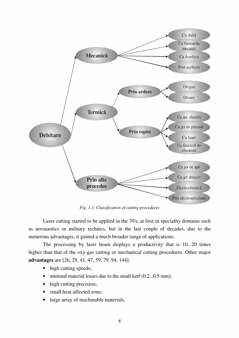
The choice of a cutting procedure can be made function of the precision imposed
to the cut parts, of the material's hardness, its quality and the procedure's energy
consumption. Figure 1.1 presents the general classification of cutting procedures:
Compared to mechanical cutting, thermal cutting presents several advantages [11]:
• higher productivity;
• possibility to cut a very complex contour;
• possibility to mechanise and automate the process;
• reduced consumption of materials and energy;
• lower price.
There exist however also some disadvantages of thermal cutting [11]:
• it produces structural changes and changes in the chemical composition near
the cutting area;
• it produces remnant strains and stresses;
• the cut surface requires sometimes supplementary mechanical processing.
Around 85% of all thermal cutting operations are currently realised with gas flame
and oxygen [8, 87].
Due to the numerous technical-economic advantages, currently there is however
a tendency of replacing the cutting by burning with cutting by melting, especially with
plasma cutting or laser cutting.
8
DebitarePrin topire
Prin ardere
Cu daltă
Cu fierestrăumecanic
Cu foarfece
Prin aşchiere
Oxigaz
Oxiarc
Cu arc electric
Cu jet de plasmă
Cu laser
Cu fascicol deelectroni
Cu jet de apă
Cu jet abraziv
Electrochimică
Prin electroeroziune
Mecanică
Termică
Prin alteprocedee
Fig. 1.1: Classification of cutting procedures
Laser cutting started to be applied in the 70's, at first in speciality domains such
as aeronautics or military technics, but in the last couple of decades, due to the
numerous advantages, it gained a much broader range of applications.
The processing by laser beam displays a productivity that is 10...20 times
higher than that of the oxy-gas cutting or mechanical cutting procedures. Other major
advantages are [26, 29, 41, 47, 59, 79, 94, 144]:
• high cutting speeds;
• minimal material losses due to the small kerf (0.2...0.5 mm);
• high cutting precision;
• small heat-affected zone;
• large array of machinable materials.

9
Among the disadvantages of using a laser cutting system, there can be mentioned:
• higher capital costs than for other cutting systems;
• the maximal cuttable material thickness is 12 mm;
• cutting shiny metals such as aluminium or copper, where a large part of the laser
energy may be reflected outside of the cutting area, can be difficult.
Based on the technical, technological and economic characteristics of all cutting
systems presented, a comparative critical analysis was done. The main factors that
have to be taken into account, according to the speciality literature [98, 116, 120, 141,
154, 163] are:
• achievable cutting speed;
• edge precision;
• required precision level;
• types and material thicknesses that can be cut;
• dimension of the heat-affected zone;
• productivity;
• need for applying further machining stages on the cut surfaces;
• capital investment required for equipment, auxiliary materials etc.;
• operating costs;
• required skill level of the operators;
Thus, from the point of view of the cutting speed, the speciality studies indicate,
for all processed materials, a higher cutting speed with a laser beam, at lower material
thicknesses. At higher material thicknesses, however, the highest cutting speeds are
registered with plasma jet cutting. Figure 1.2 (adapted from [141]) presents the
evolution of cutting speeds for a mild steel, a stainless steel and aluminium, machined
with a laser beam of 4000 W, a plasma jet with a current intensity of 200 A and a
water jet of 50 HP, respectively. It should be added that plasma cutting systems
sometimes cut thinner metal sheets at lower speeds due to the choice of a smaller
current intensity which would lead to a better quality and precision of the cut.
Figure 1.3 (adapted from [141]) presents a comparative graph of the cutting
precision for the case of cutting with a laser beam of 4000 W, a plasma jet with a
current intensity of 200 A and a water jet of 50 HP, respectively.
It can be noticed that, regardless of the part thickness to be cut, the highest
precision is reached with laser cutting, while the large amount of heat set free during
plasma cutting leads to lower precisions.

10
a)
b)
c)
Fig. 1.2: Cutting speed for a part made of mild steel (a), stainless steel (b) and aluminium (c),function
of the material's thickness, for the case of cutting with a 4000 W laser, a 200 A plasma jet and a 50
HP waterjet, respectively.
Fig. 1.3: Cutting precision function of the material's thickness, for the case of cutting with a
4000 W laser, a 200 A plasma jet and a 50 HP waterjet, respectively.
With regard to the specific costs, table 1.1 [141] presents a comparative
overview, considering a cutting machine with a workspace of 1.8 x 3.6 m.
Table 1.1 Comparison of capital and operating costs
Cost element 4000 W laser
200 A high density
plasma burner
Water jet / Abrasive jet
with 50 HP pump
Capital costs 500.000 USD 115.000 USD 170.000 USD
Operating costs
10 USD/hour 10 USD/hour 10 USD/hour
Supplementary costs
2 - 15 USD/hour for auxiliary gas
3 USD/hour for auxiliary gas
15 USD/hour for the abrasive

11
As a preliminary conclusion, it can be said that, for the cutting of relatively thin
metal sheets, the best technology from the point of view of precision, cutting speed
and surface quality is laser cutting, but its main disadvantage is the high cost of the
equipment.
1.2 Structural analysis of the NC cutting machines
The goal of a machine tool is to process parts by cutting, under certain
conditions of productivity, dimensional precision and surface quality. If the processing
orders are programmed with a numerical control equipment, the machine is called a
numerical control machine tool (NCMT).
Regardless of the cutting procedure employed, the components of a cutting machine
must provide following functions [30, 92, 138]:
• bringing and fastening the blanks in the work area;
• moving the work units with precisions as high as possible;
• providing an optimal distance between work unit and blank;
• tuning and maintaining the cutting parameters at optimal levels;
• cutting the blanks under optimal quality and productivity conditions.
The cutting machines, or more precisely the numerical control equipment
controlling them, must allow movements along three axes: x, y, z. Each of these
movements is done by means of a kinematic chain. The generalised functional scheme
of a feed kinematic chain used in the structure of cutting machines is presented in
figure 1.4.
Fig. 1.4: Generalised functional scheme of a feed kinematic chain
M - direct current electrical motor; MR – control mechanism;
Sig – safety mechanism; RT – trajectory changing mechanism;
PO – start/stop mechanism; UL - work unit.
I – inversion mechanism;

12
The design of an actuation system for such feed kinematic chains in the case of
modern cutting machines, where the tools is materialised by an energy beam, must
take into account the technological particularities of such machines:
• Minimal resistive forces and moments;
• Work strokes and feed rates that can vary in a relatively broad range.
Therefore, the feed system has to provide both an adequate functioning from
the point of view of stability and safety, as well as an adequate productivity. Moreover,
a high programming flexibility must be provided, in order to be able to change quickly
and efficiently the parameters of the work cycle.
1.3 Motion control systems used for cutting machines. Numerical axes
The notion of motion control defines the control of the movement's kinematic
parameters (position, speed, acceleration), as well as their correlation for the case of
motions controlled on several directions.
Generally, the structure of a motion control system has to include following
subsystems (figure 1.5):
Fig. 1.5: The block diagram of a motion control system
• control block;
• amplifier block;
• actuation block;
• mechanical motion support;
• reaction transducers;
• interface elements.
Numerical axes must provide following functions [118]:

13
displacing the work unit with the imposed feed rate, in conditions of
achieving a good regularity in time and space;
control of feed rates for a broad range of these (from a technological feed rate
in the order of mm/min, for very precise applications, to tens of m/min, for the
case of rapid positioning of mobile elements of NCMTs);
tracking the feed rate variation in the shortest possible times;
precise control of the positions of work units on each axis and precise coordination
of several axes in the case of contouring operations;
providing moments capable of surpassing all resistance forces that occur in
the process; any variation of this moment must not influence the positioning
or contouring precision and must not lead to variations in the feed rate.
The block diagram of a secondary loop for the closed-loop control of the feed
rate is presented in figure 1.6.
Fig. 1.6: Block diagram for the closed-loop control of the feed rate
In this case, a direct current servo-motor is used. The power amplifier generates the
voltage level Ub by amplifying the feed rate error signal, this being the input parameter for
the current loop. Most often, the current loop may be assimilated with a proportional
block, with a proportionality constant I/R, where R is the resistivity of the DC motor's
armature. The servomotor is controlled by means of the current through the motor Im.
Under the action of this variable, the motor produces the couple needed for accelerating
the moving masses until reaching the imposed angular speed ω. The motor couple thus
generated cancels the effect of disturbances in the system (occurring as resistive moments
and friction moments). Therefore, the usage of DC servomotors represents an optimal
solution for the actuation of this type of systems.

14
1.4 Aspects of the analysis of automated systems from NC machines
If a nonlinear function yi is considered, representing the dynamic behaviour of the element i from the system,
)( ii xfy = , (1.1)
the differential equation of the global system can be written as:
0)(,...,)(
,)(
),(,...,)(
,)(
1
1
1
1
=
−
−
−
−
txdt
txd
dt
txdty
dt
tyd
dt
tydf
m
m
m
m
n
n
n
n
, (1.2)
or:
x(t)b + dt
dx(t)b+ ... +
dt
x(t)db
+ dt
x(t)db =y(t)a +
dt
dy(t)a ... +
dt
y(t)da +
dt
y(t)da
01-1m
-1m
-1m
m
m
m01-1n
-1n
-1nn
n
n +
. (1.3)
The general solution of this equation is of the form: )()()()( tytytYty sftftl ++= , (1.4)
where: ytl(t) is the free transitory component, which does not depend on the input, being determined only by the system's dynamics and by the initial non-zero output conditions;
ytf(t) is the forced transitory component, depending both on the system's
dynamics and on the input;
ysf(t) is the forced component in stabilised regime.
Differential equations such as the one described by (1.3) can be solved relatively
easily using the Laplace transform. Then, the differential equation is changed into a
polynomial equation:
If: ., Y(s)s=F(s) atunci dt
y(t)d=f(t) n
n
n
(1.5)
In the current case, by applying the Laplace transform to the initial differential equation, there results:
.X(s)b+ sX(s)b +...+ X(s)sb +
X(s)sb =Y(s)a + sY(s)a +...+ Y(s)sa + Y(s)sa
01-1m
-1m
mm01
-1n-1n
nn +
(1.6)
The transfer function can be defined as ratio between the Laplace transform of the output parameter and the Laplace transform of the input parameter, for initial zero conditions:
a+sa+...+sa+sa
b+sb+...+sb+sb=
X(s)
Y(s)=H(s)
011-n
1-nn
n
011-m
1-mm
m . (1.7)

15
1.5 Study of the dynamic behaviour and of the kinematic precision in
NC cutting machines
Any error occurring in the functioning of a motion control system is
automatically transformed into errors when generating the parts' contour. Experimental
researches presented in the speciality literature [2, 9, 16, 21, 118, 127] indicated that
errors introduced by the functioning of numerical axes are the main component in the
total amount of errors occurring during the functioning of a NC machine-tool.
Among the factors significantly influencing the dynamic behaviour and the
kinematic precision of numerical axes an important role is held by the dynamic constraints.
Within this category of factors there needs to be mentioned firstly the system's dynamic
untuning. It can manifest itself through the existence of different amplifying factors on each
axis, case in which especially the contouring error in stationary regime is affected, or by
different time constants on each axis, case in which the transitory regime is negatively
affected. An element that would require a more in-depth study, as yet not fully solved
[118, 127], is the presence or absence of contouring errors in the case of perfectly
tuned numerical axes. Such errors occur for example when a circular contour is cut, it
being deformed as an ellipse along the axis with a smaller amplifying factor.
When cutting parts with 90º corners at constant speed (without stopping in the
corner point), contouring errors are noticeable that depends on the dynamic behaviour of
the numerical axes.
The constructive and functional elements that allow the optimisation of the
dynamic behaviour from the point of view of work parameters stability are the
controllers. These are feedback control systems with the role of maintaining a
constant input value during the functioning cycle of the controlled system.
A PID controller is characterised by the fact that the correction signal at its output
represents a combination of three components: a proportional component (P), an integral
one (I) and a derivative one (D), resulting from the processing of the error signal [42].
The functioning of a feed-forward controller is relatively simple: a transfer
function G0-1
(z) is introduced in the control system, that is the precise reverse function of
the system's global transfer function G(z), so that:
G0-1
(z) · G(z) = 1, (1.8)
and the reference input value (the imposed value) becomes equal to the system's output
value (the realised value) [8, 58, 118]. Feed-forward controllers reduce mainly the
tracking errors Ex and Ey on the two axes, but the contouring error ε is indirectly
reduced too as a result [118].

16
1.6 Preliminary conclusions and objectives of the thesis
As a consequence of the facts presented above, the current thesis aims at carrying
out theoretical and experimental researches regarding the evaluation of dynamic behaviour
and kinematic precision of feed kinematic chains from the structure of NC laser cutting
equipments, as well as the investigation of means to improve these elements.
The thesis' proposed objectives are:
From the point of view of theoretical researches
• elaborating a mathematical model for the numerical axes using as execution
element the DC servomotor. As has been shown earlier, this constructive solution is
currently the best technical-economic compromise for this kind of equipment;
• taking into account at the model's construction of the influence of as many
disturbance factors as possible (masses, inertia forces, possible technological
forces). There is an obvious need for the modelling results to be as close as possible
to the studied system's real behaviour. For this, it is necessary for the modelling to
take into account as many as possible of the influences exerted during functioning
on the numerical axes;
• introducing in the model's structure of the influence of numerical control (discrete
transfer functions, sampling periods, numerical controllers). The methods being
currently applied in studying linear continuous systems cannot be used also for
studying numerical axes. Computer control implies not only a structural modification
of servosystems for the automated position control, but it is also necessary to tackle
this study with methods specific for automated control systems with sampling;
• elaborating mathematical models for generating reference parameters, both in
rapid positioning regime and in linear and circular interpolation regime. The
functioning time of numerical axes, in either of the two regimes, is
approximately equal, so both situations have to be studied. Furthermore,
kinematic and dynamic conditions differ significantly in the two cases, requiring
their separate tackling;
• study through simulation of the dynamic behaviour and of the kinematic precision of
numerical axes. The study through simulation aims at emphasising the influence of
various factors (constructive solutions employed, variation of the kinematic
parameters, disturbance factors etc.) on the numerical axes' behaviour. Also, though
simulation there will be identified the main methods and techniques for improving
the axes' behaviour.

17
From the point of view of experimental researches
• studying the influence of the various categories of technological factors,
including the control level at the numerical control, on the structural,
mechanical and surface quality characteristics of parts processed by cutting.
There will be realised by cutting with energy beams (oxy-gas, laser), from
sheet-type blanks, with different cutting regimes, parts that will later be
analysed not only from a dimensional and shape point of view, but also from the
point of view of microstructure, microhardness and roughness.
• experimental research of the precision of numerical axes from the structure of
NC machines for cutting with energy beams, in positioning regime and in
contouring regime. This implies the actual unfolding of determinations,
following an experimental programme according to the current norms, including
the processing of the acquired data;
• experimental validation of the theoretical methods for improving the dynamic
behaviour and the kinematic precision of numerical axes. The validity of solutions
resulting from theoretical researches will be checked, by carrying out the needed
modifications on the experimental system, in order to improve its behaviour.

18
Chapter 2
THE MATHEMATICAL MODEL OF A FEED DRIVE FROM
THE STRUCTURE OF NUMERICAL-CONTROL CUTTING
MACHINES
2.1 General considerations regarding the mathematical modelling
The behaviour of an automated system, under given exploitation conditions, may
be described by group of algebraic and differential equations that express the dependence
of the output parameter on the input parameter. Based on this, a mathematical model can
be obtained, that allows not only the description of the system's current behaviour, but
also the behaviour in conditions of modified working conditions.
In order to define a mathematical model for a numerical axis, it is necessary to
go through following steps [118]:
1. Decomposing the analysed system in its basic components that take part in realising its functionality and equating these components with pure (and if possible linear) dynamic elements;
2. Writing the characteristic equations for each of these elements; 3. Linearising these equations (in order to achieve a linear global system); 4. Determining the interconnection relationships between the component dynamic
elements. By eliminating the intermediate variables, one can determined the differential
equation of the global system. This equation (defined through relation (1.2) in the previous chapter), together with the initial conditions: values of x and y parameters and of their derivatives function of time at the moment t = t0, composes the system's mathematical model.
2.2. Structure of the studied numerical axis
Starting from the basic elements presented in the previous chapter and from the
idea that an actuation based on DC motors is more efficient than the one based on AC
motors, the theoretical researches regarding the modelling and simulation of a
numerical axis' control, presented in the following, were based on the actual case of a
feed kinematic chain having as execution element a DC servomotor.

19
The principle structure of such a numerical axis is presented in figure 2.1. In
this case, there was adopted the solution of mounting the incremental transducer on the
servomotor's shaft.
Fig. 2.1: Structure of a numerical axis with DC servomotor
RP - position controller; I – integrator;
CNA - numerical-analogical converter; TG - speed voltage generator;
A – amplifier; TID - incremental displacement transducer
M - DC servomotor
The position reference θc, which in the context of the systemic approach
represents the main input parameter in the system constituted by the numerical axis, is
generated at time intervals equal to the sampling period T by the control equipment's
interpolator. It is then compared to the feedback parameter from the incremental
transducer, sampled at the same time interval.
The output parameter in this system is the effective displacement of the work unit on
the considered direction.
2.3. Determining of the relationships that characterise the functioning
of the numerical axis
In order to correctly determine the analysed numerical axis' characteristics, the
starting point has to be the axis' global transfer function. For determining this function,
there need to be taken into account, according to the theory of automated control, the
transfer functions of each component, taken separately.
20
For a DC motor, the system's transfer function for the disturbance (static
moment Ms) is:
sτ+
KKRB+
R
= (s)M
ω(s) =
)ML(
L(ω
m
vt
ss ⋅1)
. (2.1)
Following the calculations, in the closed speed control system, the revolution
speed can be written as:
][ (s)MKK+RB
R-
KK+RB
KKU(s)
s+1=(s) s
vtvt
ta
⋅τ
αω (2.2)
or
s+1
(s)MK-U(s)K=(s)
s21
τω . (2.3)
where two components of the transfer function of the closed speed loop can be noticed:
function of the input (control voltage) and function of the disturbance (static moment).
Applying the Laplace transform, the motor's revolution speed ω(t) could be
written as:
)e-(1)MKK+RB
RK-U
KK+RB
KK(=(t)
t-
s
vt
t
vt
ta τ⋅α⋅αω . (2.4)
At maximal values of the control voltage Um and of the static moment Msm, the
motor's revolution speed must reach a maximal value ωm:
MKK+RB
RK-U
KK+RB
KK= sm
vt
tm
vt
tam
⋅α⋅αω . (2.5)
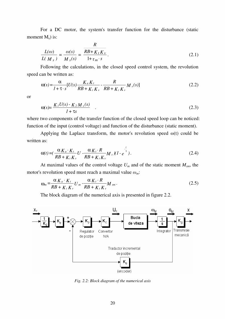
The block diagram of the numerical axis is presented in figure 2.2.
Fig. 2.2: Block diagram of the numerical axis

21
The incremental transducer is characterised by its amplifying coefficient Ke,
defined by the number of impulses sent during a full rotation of the lead screw:
[imp/rad] 2
N=K
imp
eπ
, (2.6)
where Nimp is the number of impulses emitted by the transducer during a rotation.
The Laplace transform of the position error can be expressed as:
K+s+s
(s)MKK+(s)x)ss+(1K
K
=E(s)2
sg2r
g
e
⋅τ
τ ][
. (2.7)
Relation (2.7) allows the distinguishing of the two components of the transfer
function, relative to the input and relative to the disturbance:
K+s+s
s)+s(K
K
= (s)x
E(s) = (s)H 2
2
g
e
r
0⋅τ
τ
; (2.8)
K+s+s
KK =
(s)M
E(s) = (s)H 2
2e
s
0Pτ
. (2.9)
These two relations represent the global transfer functions of the numerical axis
with DC servomotor and will be used subsequently for its mathematical modelling.
2.4. Analysis of the kinematic precision of the numerical axis
The problem of motion control of numerical axes in the case of cutting
machines must be discussed for two distinct situations:
- the case of rapid positioning motions (point by point positioning); during such
displacements there are no machining operations, reaching of the final point under the most
accurate conditions in the shortest possible time being most important;
- the case of machining (contouring) motions, carried out with the technological
feed rate, on one or several axes; in this case, the realised trajectory and the accuracy with
which it reproduces the imposed trajectory, is essential.
An important parameter in this regard is the tracking error, defined as distance
between the instant values of the realised position and of the imposed position.
Figure 2.6 presents the variation of the kinematic parameters (distance covered,
speed/feed rate, acceleration) for a point by point positioning cycle on a movement axis.

22
Fig. 2.3: Distance covered, speed/feed rate, acceleration) for a point by point positioning cycle
Tac, sac - acceleration time, distance covered during acceleration
Tvc, svc - duration of movement at constant speed, distance covered with constant speed;
Tdc, scc - duration of deceleration, distance covered during deceleration;
For a positioning displacement, it is easy to realise in practice a trapezoidal
speed profile, but it presents the disadvantage that the acceleration varies abruptly,
which might pose problems especially during contouring operations, through the
occurrence of the "jerking" phenomenon, which influences negatively the accuracy of
the realised contour and introduces vibrations into the system.
Nevertheless, if considering displacements on only one axis, the trapezoidal
profile is the most used one, being easier to generate than a paraboloidal one and
therefore it is found with all motion-controller-type industrial system. Moreover,
in practice the jerking is considerably diminished, because the delaying effects
introduced by various elements of the control system determine the actual shape
to be close to the paraboloid one.
Considering the acceleration equal in absolute value on the acceleration and
deceleration phases, respectively, and considering also the periods ta and td equal, between
the kinematic parameters for a trapezoidal profile there can be written following relations:
23
a
vtt da
max== ; (2.10)
)(max
dact
ct ttTv
st +−== ; (2.11)
22
maxmax dada
tvtvss
⋅=
⋅== ; (2.12)
a
vss da
⋅==
2max ; (2.13)
ctct tvs ⋅= max , (2.14)
where: a is the acceleration during the acceleration and deceleration phases;
sa – distance covered during the acceleration period;
sd – distance covered during the deceleration period;
sct – distance covered during the period of movement at constant speed.
The contouring regime implies the correlation in time of the displacements on
the numerically controlled machine axes and involves the introduction in the
equipment's memory and the processing of a very large amount of coordinates of
points from the trajectory that defines the constructive shape of the part.
For practical reasons, however, the trajectory is decomposed in elementary curves, and in the equipment's memory there are introduced only the coordinates of the initial and final points, the coordinates of intermediate points being calculated by the equipment by means of interpolation algorithms. These can be easily implemented in the software. Currently there are mainly two types of interpolators:
• interpolators using the reference impulses technique;
• interpolators using the binary words technique. The reference impulses technique, the first to be implemented, was
implemented by means of two method: the method of differential digital analysis (DDA) and the method of direct function calculus (DFC). These methods have however the disadvantage of using a large amount of mathematical operations (in the case of the DDA method) or of logical operations (in the case of the DFC method). Therefore currently there is used especially the binary words (reference words) technique, which will be also tackled in more detail in the following. In the case of circular interpolation, the values of reference words for the control of the two axes, at the moment Tk, can be described with the relations:
⋅π
=
⋅π
=
,2
cos
;2
sin
kk
kk
TT
Ry
TT
Rx
(2.15)
24
where: R is the radius of the circle of which the arc is a part; T – period of the sine and cosine functions (depending on the feed rate on the axis). Tk can be determined function of the sampling period according to the relation:
sk TkT ⋅= . (2.16)
The angular displacement increment θincr is determined with the relation:
ssincr TR
vT
T⋅=⋅
π=θ
2, (2.17)
and the linear displacement increment lincr with the relation:
sincr
incr Tv
Rlπ
=π
θ⋅=
22 , (2.18)
The equations found within this chapter for realising the mathematical model were used in the next stage of theoretical researches, for the numerical simulation of the behaviour of a feed system from the structure of a laser cutting machine, presented in chapter 3 of this thesis, for the calculus of the optimal functioning parameters of the DC servomotor used for actuation.
Thus, the equations characterising the functioning of the numerical axis were implemented for the actual case of the system with DC servomotor.
Also, the mathematical model that was determined here, was used also for the configuration and functional optimisation of the system employed for experimental researches, detailed in chapter 4 of this thesis.
25
Chapter 3
STUDY BY SIMULATION OF THE BEHAVIOUR OF
THE FEED SYSTEM FROM THE STRUCTURE OF A NC
LASER CUTTING MACHINE
3.1 Generalities regarding the analysis through simulation of the
numerical axes
Numerical simulation is a work method in systems analysis, by which, with the
help of adequate hardware and software, a system's model can be evaluated over a period of
time, collecting data on the setup and functioning of the model under various conditions and
using those data for estimating the real characteristics of the analysed system [75].
The simulations that were carried and that are presented in the following were
realised with the help of the MATLAB & Simulink software package, version 7.0.
MATLAB (MATrix LABoratory) is a performant, interactive software
environment, destined for engineering and scientific numerical calculations, that
appeared in a first shape at the end of the 70's and has been extended considerably in
the last few year. Its declared goal is to help the users to solve a large array of
analytical and numerical problems using methods based on matrix calculations,
offering easy access and simple implementation possibilities for state-of-the-art
numerical algorithms [82, 148, 161].
Simulink is a software for modelling, simulating and analysing linear or nonlinear,
continuous, discrete or hybrid dynamic systems, integrated with the Matlab software.
3.2. Structure and characteristic parameters of the studied numerical axis
In order to reflect the influence of the numerical control on the modelled system
and the model's hybrid character, the functional block diagram used for the study by
simulation of the behaviour of a numerical axis with DC servomotor, realised in the
Matlab & Simulink software package was completed with following elements (fig. 3.1):
- an extrapolation block (zero-order extrapolator) on the direct way;
- a sampling block on the feedback loop. for sampling the quantified signal
from the transducer.

26
v
Viteza
t
Timp
Ms
Uc
Omega
Subsistem
bucla de viteza
Kp
Regulator
pozitieKg
Kg x
Pozitia
Moment rezistent
static1
s
Integrator
pozitieKe1/Kg
Extrapolator
de ordinul zero
Extrapolare si retinere
semnal de reactie
Ke
Encoder
du/dt
Derivative
Kc
Convertor
numeric/analogic
Comparator
pozitie
Baza de timp
Afisaj viteza
Afisaj pozitie
Afisaj acceleratie
a
Acceleratia
1
Fig. 3.1: Block diagram used for the study by simulation of the numerical axis' behaviour
It was decided to analyse the numerical axis' dynamic behaviour both in
positioning regime and in contouring regime, by simulation.
Therefore, in the following there have been determined the values of parameters
needed for simulating the functioning of a numerical axis using a DC servomotor of
type Sanyo T 730-012 [158].
The mentioned servomotor has following characteristics:
- nominal couple Mn = 1,18 Nm;
- revolution speed nn = 2500 rpm;
- nominal current intensity In = 5,2 A;
- maximal impulse current intensity Imax = 40 A;
- nominal voltage Un = 75 V;
- resistivity at the terminals la borne Ra = 1,1 Ω;
- constant of the motor couple Kt = 0,273 Nm/A;
- speed coefficient Kv = 28,6 . 10-3 V/min-1;
- inertia moment Jm = 0,270 . 10-3 kgm2;
- viscous friction coefficient Bm = 0,039 . 10-3 Nm/min-1.
The speed voltage generator constant is: Kth = 7 . 10-3 V/min-1.

27
In the following the inertia moment for the whole system, reduced to the engine
shaft was calculated, considering that the maximal allowable speed on the axis is
vmax= 5 m/min = 0.0833 m/s:
001165,000027,000089532,000000088,0 =++=++= mspt JJJJ kgm2.
Similarly, there were determined the values of the maximal angular acceleration that
could be developed by the engine, of the linear acceleration, of the loop's time constant,
attenuation factor, amplifying factor and damping factor.
Based on these calculations it was possible to generate a data set used for
simulating the functioning of the numerical axis.
3.3 Study by simulation of the dynamic behaviour in positioning regime
In this research stage it was sought to analyse the behaviour of the numerical
axis with DC servomotor in positioning regime, at the displacement on a single
movement direction, in fast approach-retreat regime (in the absence of technological
forces) and in technological feed regime (in the presence of technological forces).
The necessary reference kinematic parameters (distance, speed (feed rate),
acceleration), were generated with the help of a Matlab program, at time intervals of 1
ms (10 × sampling period), following a trapezoidal speed profile.
Figure 3.2 shows the variations of the reference kinematic parameters for a
rapid approach movement and for a technological feed movement, respectively.
0 0.1 0.2 0.3 0.4 0.5 0.6 0.7 0.80
2
4
6x 10
-3
Pozitie
0 0.1 0.2 0.3 0.4 0.5 0.6 0.7 0.80
0.01
0.02
Viteza
0 0.1 0.2 0.3 0.4 0.5 0.6 0.7 0.8-0.5
0
0.5
Accele
ratie
Timp (s)
Fig. 3.2: Reference kinematic parameters for a technological feed movement

28
Using the results obtained following the mathematical calculations carried
out in paragraph 3.1, in the following there was simulated the system's dynamic
behaviour both for a fast approach and for a technological displacement, with the
help of the Matlab v.7.0 software and using the diagrams developed in Simulink
and presented in chapter 2 of the current doctoral thesis.
The results of simulations (the graphical display of the variation of output
parameters function of time) are presented in figures 3.3 - 3.5.
0 0.1 0.2 0.3 0.4 0.5 0.6 0.7 0.8 0.9 10
0.01
0.02
0.03
0.04
0.05
0.06
Timp [s]
Spatiu [
m]
Spatiul parcurs pe cursa rapida
0 0.1 0.2 0.3 0.4 0.5 0.6 0.7 0.8 0.9 1
-0.05
0
0.05
0.1
0.15
0.2
0.25
0.3Viteza pe cursa rapida
Timp [s]
Viteza [
m/s
]
Fig. 3.3: Distance covered during the rapid
approach
Fig. 3.4: Speed during the rapid approach
0 0.1 0.2 0.3 0.4 0.5 0.6 0.7 0.8 0.9 1-2
-1.5
-1
-0.5
0
0.5
1
1.5
2
Timp [s]
Accele
ratia [
m/s
2]
Acceleratia pe cursa rapida
Fig.3.5: Acceleration during the rapid approach
As can be seen especially from the speed and acceleration graphs above, the system's dynamic behaviour during the technological feed regime is unsatisfactory, because there exist very large oscillations.
An efficient method for tackling this problem, recommended also by the speciality literature [27, 33, 118, 139], is the tuning of the controller as for the case of a
29
continuous system. In this respect, the loop's amplifying factor was considered constant, both for the case of a continuous system and for the case of the hybrid system.
The amplifying factor is determined with the relation:
en
p
pd
KU
KK
⋅
=
−12
. (3.1)
where: Kpd is the controller's amplifying factor in the digital system variant; Kp - the controller's amplifying factor in the continuous system variant; KBV - the speed loop's amplifying factor.
Replacing with the corresponding numerical values, the amplifying factor is:
39,386506725000009765,0
15846,96
25002
815846,96
114
=⋅
=
⋅
=
−
pdK
The simulation was then redone with this new value of the amplifying factor. It can be noticed that under the new conditions, the oscillations are much smaller and there were no positioning errors.
In the following, with the tuned system, its behaviour during a technological feed was tested in the presence of a resistive moment of 1 Nm, as disturbance factor in the analysed system. It can be noticed that the disturbance is being annulled quickly.
The next step comprised the simulation of the system's dynamic behaviour, starting from the mathematical model that was presented earlier. For this, in a first phase there were analysed the system's reactions to a position ramp-type signal (as well as speed step and acceleration impulse), both in the presence and in the absence of a static resistive moment. Based on these results, following preliminary conclusions regarding the behaviour
of numerical axes with DC servomotor within NC cutting systems can be drawn:
• The tuning of controllers is a complicated process that has to be carried out
both analytically and by successive trials;
• The simulated behaviour in the two functioning regimes is in agreement with the
requirements for numerical axes: relatively small and constant, thus easily
compensable positioning errors (in the order of tens of micrometers), good
dynamic behaviour;
• The system is very robust with regard to resistive-moment-type disturbances
(positioning and speed errors are basically constant for resistive moments
between 0 – 1 Nm).
Based on the realised model and simulation diagram and on the above conclusions,
it was possible to tackle the next steps of researches, which imply the study by simulation of
the multiaxial movement and the unfolding of corresponding experimental researches.

30
3.4 Study by simulation of the generation, by cutting, of 90°°°° corners
The generation of 900 corners, without stopping in the corner point, marks one
of the situations in which the numerical axes' dynamic behaviour decisively influences
the machine's contouring precision.
The quality of the transitory regime (presence or absence of overregulation,
size of increasing and of stabilisation times etc.) influences the errors in the corner
point. It must be determined, however, whether the error at corner generation is
reduced only to the error in the corner point, determined by the behaviour of the
numerical axes in transitory regime, or whether there exists also an error determined
by the behaviour of the two orthogonal numerical axes in stationary regime. For
studying this situation through simulation, there has been realised in Simulink the
diagram presented in figure 3.6.
vy
Viteza axa y
vx
Viteza axa x
t
Timp
Subsistemul
axei y
Subsistemul
axei x
Out
Sistem abilitat
pentru generarea
impulsurilor pe axa Y
Out
Sistem abilitat
pentru generarea
impulsurilor pe axa X
Referinta
y
Pozitia axa y
x
Pozitia axa x
>
Operator
relational
axa Y
<=
Operator
relational
axa X
refy
Cuvinte de referinta
axa Y
refx
Cuvinte de referinta
axa X
11
12:34
Ceas digital
Actuala
ay
Acceleratia axa y
ax
Acceleratia axa x
Fig. 3.6: Block diagram for simulating the generation of 90
0 corners

31
In the following, the generation of corners with an identical amplifying factor of the position controller on both orthogonal axes: Kpdx=Kpdy= 39.38 was studied, considering at first that the resistant moment is 0. This leads to the graphs of displacement, speed and acceleration shown in figures 3.7 – 3.11. The system obviously had an unsatisfactory behaviour in the corner point, so the profile was also negatively influenced.
0.92 0.93 0.94 0.95 0.96 0.97 0.98 0.99 1 1.01 1.02
0
5
10
15
20
x 10-4
Timp [s]
Spatiul [m
]
Spatiul parcurs pe X
Ep = 2.86*10-4
distanta impusa
distanta parcursa
__
__
0.98 0.99 1 1.01 1.02 1.03 1.04
0.093
0.094
0.095
0.096
0.097
0.098
0.099
0.1
0.101
Timp [s]
Spatiu [
m]
Spatiul parcurs pe Y
Ep = 1.32*10-4
distanta impusa
distanta parcursa__
__
Fig. 3.7:Distance covered on the x axis Fig. 3.8: Distance covered on the y axis
0 0.2 0.4 0.6 0.8 1 1.2 1.4 1.6-0.04
-0.02
0
0.02
0.04
0.06
0.08
0.1
0.12
0.14
Timp [s]
Viteza [
m/s
]
Variatia vitezei in functie de timp
viteaza pe x
viteza pe y__
__
0 0.2 0.4 0.6 0.8 1 1.2 1.4 1.6-25
-20
-15
-10
-5
0
5
10
15
20
25
Timp [s]
Accele
ratia [
m/s
2]
Variatia acceleratiei in functie de timp
acceleratia pe x
acceleratia pe y__
__
Fig. 3.9: Speed variation function of time Fig. 3.10: Acceleration variation function of time
0 0.2 0.4 0.6 0.8 1 1.2 1.4 1.6-15
-10
-5
0
5
10
15
Timp [s]
Cure
ntu
l [A
]
Variatia curentului in functie de timp
curentul pe x
curentul pe y__
__
Fig. 3.11: Current intensity variation function of time

32
Next, a resistant moment due to inertia forces was taken into account, with the values on the x and y axis: Mix= 0.23 Nm and Miy= 0.69 Nm. Following the simulation it was noticed that the error Ex increases, reaching a value of 0.0005 m and also an error appeared on the y axis. While being small, Ey = 0.0001 m, it represents a shape error and thus influences the part's dimensional precision.
First it was attempted to reduce the system's oscillations by introducing in the position controller a derivative component, both for the x axis and for the y axis. The simulations run with this setup proved however that this derivative component did not influence the contour errors, they maintaining the initial values.
Another solution studied for improving the system's behaviour was the cutting with different amplifying factors on the two axes. In order to study this possibility, the damping factor on the x axis was kept at the value 1=ξ , while on the y axis, a damping factor of
2,1=ξ was implemented. It was noticed that the positioning errors decrease both on the x
axis, Ex = 5.48 .10-4 m and on the y axis, Ey=1.06 .10-4 m, the acceleration on the y axis decreases to aymax= 9.78 m/s2, and the current intensity is also smaller, remaining within the limits imposed by the employed motor. Most importantly, the speed's oscillation is very small, of about 0.1 m/s. The actual results are presented in figures 3.12 - 3.14.
0 1 2 3 4 5 6 7 8 9 10
x 10-3
0.091
0.092
0.093
0.094
0.095
0.096
0.097
0.098
0.099
0.1
X (BLU=0.001)
Y (
BLU
=0.0
01)
Generarea unui colt (Kpdx=19.69; Kpdy=13.68)
traiectorie programata
traiectorie realizata__
__
Fig. 3.12: Cutting of the 90
0 corner with Kpdx = 19.69; Kpdy=13.68
0 1 2 3 4 5 6 7 8
x 10-4
0.099
0.0991
0.0992
0.0993
0.0994
0.0995
0.0996
0.0997
0.0998
0.0999
0.1
X (BLU=0.001)
Y (
BLU
=0.0
01)
Generarea unui colt (Kpdx=19.69; Kpdy=13.68)
traiectorie programata
traiectorie realizata__
__
0.0592 0.0594 0.0596 0.0598 0.06 0.0602
0.099
0.0992
0.0994
0.0996
0.0998
0.1
0.1002
X (BLU=0.001)
Y (
BLU
=0.0
01)
Generarea unui colt (Kpdx=19.69; Kpdy=13.68)
traiectorie programata
traiectorie realizata
__
__
Ex
Ey
Fig. 3.13: Detail from fig.3.12 (corner area) Fig. 3.14: Detail from fig. 3.12 (error)
33
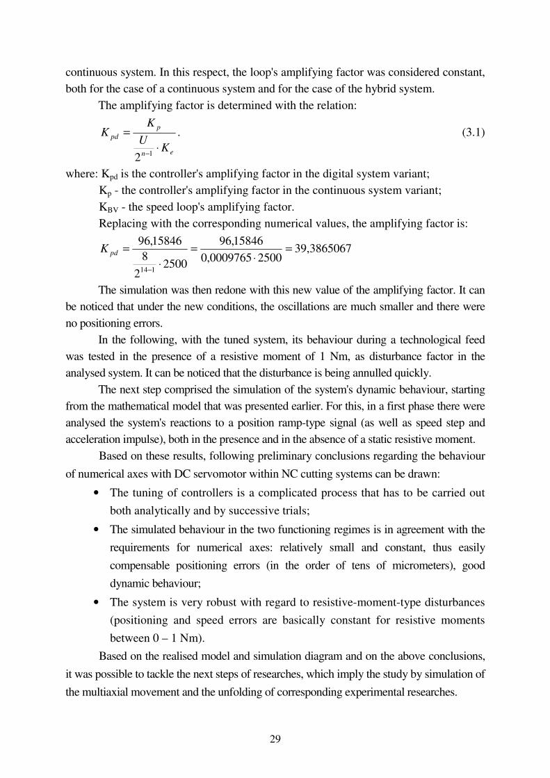
3.5 Study by simulation of the generation, by cutting, of circular contours
This chapter presents studies with regard to the numerical simulation, with the
Matlab & Simulink software package, of the generation of a circle with the radius of
30 mm, whereby it was attempted to minimise the contouring error by modifying
the technological parameters and the parameters of the motion control system.
In a first stage, there was studied the evolution of the contouring error for a feed rate
along the axis of 0.025 m/s and a sampling period of 0.001 s. Then the feed rate was
modified in steps to the value of 0.0133 m/s and the simulations were redone in order to
determine to what extent the feed rate influences the contouring error.
Then, as for the generation of the 90° corner, it was attempted to optimise the system
from the point of view of a reduced contouring error, by modifying the amplifying factor on
one axis at the time from Kpd = 39.38 la Kpd = 19.69. Also, a random disturbance was
introduced, which varies between a minimal value and a maximal value equal to the
laser beam radius of 0.02 m.
vy
Viteza axa y
vx
Viteza axa x
t
Timp
Subsistemul
axei x1
Subsistemul
axei x
Referinta
y
Pozitia axa y
x
Pozitia axa x
Generare
cuvinte de referinta
axa x
Generare
cuvinte de referinta
axa y
11
refy
Cuvinte de referinta
axa Y
refx
Cuvinte de referinta
axa X
0
30
12:34
Ceas digital
Actuala
ay
Acceleratia axa y
ax
Acceleratia axa x
Fig. 3.15: Block diagram used for simulating the generation through cutting of a circle

34
The simulation was based on the block diagram presented in figure 3.15,
realised with the Simulink software.
Figures 3.16 and 3.17 present the trajectory resulting when using a feed rate of
0.025 m/s, comparatively with the programmed trajectory and a detail of those trajectories.
As can be seen in figure 3.16, there exists a contouring error between the generated profile
and the programmed one, but it is small enough to not be visible for the scale used in fig.
3.17. The maximal value of the contouring error on the x axis is of 0.0672 mm, while the
maximal error on the y axis is of 0.3449 mm.
0 10 20 30 40 50 60 70
-30
-20
-10
0
10
20
30
Axa X
Axa Y
Eroarea de pozitie la generarea unei traiectorii circulare
traiectorie programata
traiectorie realizata__
__
58.8 59 59.2 59.4 59.6 59.8
3.5
4
4.5
5
5.5
6
6.5
7
7.5
Axa X
Axa Y
Eroarea de pozitie la generarea unei traiectorii circulare
traiectorie programata
traiectorie realizata__
__
Fig. 3.16: Positioning error at the generation of
a circular trajectory for v = 0.025 m/s
Fig. 3.17: Detail from fig.3.16
An important factor to be analysed in this case is the influence of the feed rate
on the contouring error. For this, the feed rate has again been varied in steps. It could
be noticed that, by decreasing the feed rate from 0.025 m/s la 0.0133 m/s, the contouring
errors also decrease to approximately half the initial values, their maximal values being
Exmax = 0.0358 mm and Eymax = 0.1839 mm. It can be therefore said that between the feed
rate and contouring error there is an almost linear dependence.
However, decreasing the cutting speed as method of increasing the cutting precision
is suitable only for complex parts or for parts produced in small batches. In the case of large
batches, it is not accepted by producers, as it considerably reduces the machine's
productivity.
Therefore, another way to optimise the cutting conditions with regard to the
trajectory generation precision. So, while keeping the feed rate at 0.025 m/s, the
amplifying factor was reduced successively on one axis at the time, from 39.38 to
19.69.

35
When reducing the amplifying factor on the x axis, the contouring error on the x
axis decreases to a maximal value Exmax = 0.0336 mm, while on the y axis the error
remains unchanged Eymax = 0.344 mm. When modifying the amplifying factor on the y
axis, no improvement is noticed, to the contrary, the maximal error on the y axis
reaches 0.6898 mm.
As a conclusion of the simulations carried out and described in this subchapter,
it can be concluded that in the case of circular interpolation, if it is sought to maintain
a high productivity, the best solution is to adopt different amplifying factors on the two
axes.

36
Chapter 4
EXPERIMENTAL RESEARCHES REGARDING THE
OPTIMISATION OF THE DYNAMIC BEHAVIOUR OF
KINEMATIC FEED CHAINS FROM THE STRUCTURE OF
NUMERICAL CONTROL CUTTING MACHINES
The experimental researches carried out within this doctoral thesis have
targeted the practical determination of the optimal setup parameters at a NC cutting
machine and, at the same time, the validation of the corresponding results achieved
through simulation with the help of the software package Matlab & Simulink and
presented in chapter 3 of the thesis.
These researches were carried out on machines and equipments from the
Faculty of Engineering of the "Lucian Blaga" University of Sibiu and from the company
S.C. COMPA S.A. Sibiu, respectively.
4.1 Equipments used for the experimental researches
The technological system used for the unfolding of experimental
researches comprised a NC machine tool for laser cutting MAZAK NT-X48
Champion, an oxy-gas cutting machine OXYTOME HPC 20 and two coordinate
measuring machines ZEISS PRISMO 7 and ZEISS CONTOURECORD 1600 D,
respectively.
The cutting machine OXYTOME HPC 20, made by the company SAF-FRO,
component of the AirLiquide Group [151], is an automated portal-type machine that
can cut metal sheets with a width of up to 2425 mm. It can be equipped on demand
also with a Nertajet HP plasma cutting system. The control system HPC Digital Process
allows a continuous monitoring of the gas flow and of the cutting process [10], while the
cutters are equipped with pilot valves for preheating, leading to a higher productivity.
In order to carry out the experimental researches with regard to laser cutting, which
are the main part of the researches presented in the following in this chapter, a laser cutting
machine MAZAK NT-X48 Champion manufactured by Yamazaki Mazak Optonics
Europe [165] was used, from the endowment of the company S.C. COMPA S.A Sibiu. The
machine is equipped with a CO2 laser.

37
Given the fact that the numerical control unit Mazatrol L-32B of this machine was
defective and the company did not want to invest at that moment in a new such unit, it was
attempted to replace it with a numerical control unit Fagor 8055 from a NC milling machine.
This replacement was justified by the fact that the company DANOBAT from Spain
produces laser cutting machines equipped with Fagor 8055 NC units [166].
The numerical control unit FAGOR 8055 [142, 166] is realised in a modular
system and can control up to 7 numerical axes and 2 shafts. It allows block processing
times of up to 1,5 ms, can analyse the cutting head trajectory with up to 75 blocks in
advance and offers the possibility of an advanced control of the displacement for
avoiding the occurrence of "jerking". This unit uses DC servomotors for the control of
numerical axes.
Prismo 7 S-Acc is a portal-type coordinate measuring machine, manufactured
by the company Zeiss from Germany. It represents an improved version of the Prismo
Navigator measuring system, is equipped with a VAST measuring device and allows
the active scanning of the parts to be measured [156].
The CONTOURECORD 1600D measuring machine, also manufactured by
the company Zeiss from Germany, is designed for the measuring and analysis of the
contours of parts [143]. Similarly to the Calypso software from the Prismo S-Acc
machine, the TiMS software integrated on the Contourecord machine and functioning
under Microsoft Windows operating system, allows not only an accurate acquisition of
the measured profile data, but also a comparison of these data with the initial design
data introduced as IGES or DXF files. Thus there can be determined both the potential
dimensional errors and position and shape errors.
4.2 The material used and the parts realised for the experimental researches
For the experiments the author has used sheet metal blanks made of S355JR
steel according to SR EN 10025-2:2004. This is a common use construction steel with
a minimal tensile strength of 510 N/mm2, used for heavily stressed metallic
construction elements, such as masts for aerial electrical lines, runways, cranes, car
chassis, large-volume reservoirs etc. [157].
This rather cheap and unpretentious material was chosen due to the fact that the
research goal was to check the optimal configuration determined for the machine and
the control equipment and less the manner in which the machining is influenced by the
nature of the processed material. Nevertheless, as is presented in the following
subchapters, some analyses were carried out also in this regard.

38
In a first phase, of this steel type there were realised, by cutting on the oxy-gas
cutting machine OYTOME 20 HPC, from steel sheet with a thickness of 20 mm, a set of 5
square-shaped parts, with a side length of 80 mm, with a central hole of 40 mm diameter
and 5 disk-shaped parts with a diameter of 60 mm and a central hole of 8 mm diameter.
The technical limitations of the machine and of the oxygas cutting procedure,
exposed through the occurrence of relatively large dimensional errors and heat-
affected area, even after the NC system was tuned in the same manner as was later
done on the laser cutting machine, have determined however the author to give up
using this machine for more detailed experimental tests.
As a consequence, the author has decided to realise more in-depth experimental
researches on the laser cutting machine MAZAK NT-X48 Champion, described earlier,
modified by replacing the defective NC unit MAZATROL 32B with a NC unit
FAGOR 8055 taken from a NC milling machine.
The parts realised on this machine were disk-shaped, with a diameter of 60 mm
and square-shaped, with a side length of 80 mm. The disk-shaped parts had a central
hole with a diameter of 8 mm, while the square-shaped ones had a central hole of 40
mm diameter, also realised by laser cutting.
Taking into account the fact that laser cutting is suitable mostly for thinner
metal sheets, these parts were cut from 400 x 400 mm steel sheets obtained by cold
rolling, with thicknesses of 3, 6 and 8 mm respectively.
From each steel sheet type and for each part shape there were realised 18 parts
each. Thus, three different cutting regimes were used, with each one being cut 12 parts
in all (both square-shaped and disk-shaped). Three of these parts were realised under
the conditions of an untuned system, while other 9 were cut with the system optimised
through various methods, according to the results of the theoretical researches by
simulation, carried out previously and described in chapter 3 of this thesis.
Some of these parts are presented in figure 4.1.
4.3 Studies concerning the influence of the cutting regime on the
mechanical and technological characteristics
In order to better assess the effect of various cutting regimes on the material of
the parts realised within the experimental researches, these were subjected to complex
analyses, consisting in microstructural, microhardness and roughness determinations in
the area adjacent to the cut, before and after the cutting.

39
Fig. 4.1: Parts realised on the laser cutting machine MAZAK NT-X48 Champion from S.C.
COMPA S.A. Sibiu as part of the experimental researches
With regard to the roughness of the cut parts, the tests carried out within the
scope of this doctoral thesis were aimed at determining the main roughness parameters,
indicated in the standard SR ISO 4287-2001 (Geometrical specifications for products.
Surface state: Profile method - terms, definitions and surface state parameters). The
tests were done with the help of the SURTRONIC 3+ roughness tester of the company
Rank Taylor Hobson and of a specialised software for the processing of the measured
data, TALYPROF, in agreement with SR ISO 4287-2001.
Following the roughness measurements and the evaluation of results, following
conclusions could be drawn:
a) No significant differences are registered between measurements done on
various areas of a part of on different parts, cut under identical conditions. This
illustrates the constancy of reproducibility at the laser cutting of metallic materials;
b) The quality of the part's cut surface is influenced mostly by the cutting speed
and by the frequency and is insignificantly influenced by the part's thickness;

40
c) There was noticed, as expected, a worsening of the cut part's surface quality as
the cutting speed increased and the frequency decreased;
d) The studied roughness parameters Ra, Rq, vary in the same manner function of
the feed rate and frequency;
e) It can be noticed that the thickness of the cut part does not significantly
influence the quality of the processed surface.
The microhardness tests were realised on an automated microhardness tester
CV-400DAT produced by CV Instruments Europe BV and currently within the
endowment of the Centre for Studies and Researches for Metal Forming from the
"Lucian Blaga" University of Sibiu.
For the microhardness test, there was chosen one part from each set of square-
shaped parts with thicknesses of 3, 6 and 8 mm, respectively, and a test sample was
extracted by cutting with a disk milling cutter from each of these parts, with a length
of 10 mm, from the area between the outer square contour and the inner circular
contour.
The microhardness tests were of HV 0.1 type, realised with a pyramid-shaped
indenter made of diamond, with a top angle of 136°±15', driven with a load of 0.1 kgf
(0.987 N) with a penetration duration of 15 seconds.
On the polished side of each analysed test sample there were realised three
parallel rows of eight indentations each, starting from the test sample's centre towards
the outer side (the rectilinear edge), the distance between indentations being of 0.05
mm.
The increasing dimension, from the sample's outer side, which was laser cut,
towards the inner side (unaffected by the laser energy) of the indentations left by the
microhardness tester's indenter in the material, indicates that, by cutting, the part's
superficial layer was hardened, but the hardness decreased gradually with the
increasing depth. On the other hand, no significant difference between the results
achieved for different cutting regimes could be noticed.
In order to examine the specific microstructural aspects that resulted through
laser cutting, the parts were subjected to grinding and polishing, after which the
metallographic etching was done.
From the analysis of the microstructures, following conclusions could be drawn,
strengthened also by the results of the microhardness tests, carried out previously:
- the material's initial microstructure reflected on the one hand the chemical
composition, with relatively few carbon, with predominant ferritic grains (which
following the etching with nital appear in white colour) mixed with pearlitic grains

41
(which following the etching with nital appear in dark colour), and on the other hand,
through the grain arrangement on rows, it reflected the obtaining of the blank by
cold rolling;
- at the material's surface, due to the thermal effect of the laser beam, there appeared a
material layer with distinctive characteristics, of slightly lighter colour, indicating the
existence of a non-equilibrium structure, of sorbite-troostite type;
- the thickness of the heat-affected superficial layer was generally very small, of under 0.3
mm. The maximal thickness is registered for medium values of the feed rate;
- using a tuned or untuned numerical axis did not affect the material's structure in
any way, the effects of tuning being limited to the recorded dimensional and
shape errors.
4.4 Studies regarding the optimisation of processing by laser cutting on
NC machine-tools
The experimental researches described in the following were carried out on the
laser cutting machine MAZAK NT-X48 Champion, modified by adding a NC unit
FAGOR 8055 and using the set of parts described earlier. They targeted on the one
hand the determining of optimal dynamic tuning coefficients for various laser cutting
regimes and on the other hand, the validation of results obtained in this regard in the
previous stage of simulating the process with the help of the Matlab & Simulink software
package.
The cutting of 900 corners, without stopping in the corner point, represents one
of the situations in which the control system's behaviour influences significantly the
machine's contouring precision.
The experimental studies presented in this subchapter had as reference base the theoretical researches by simulation described in chapter 3.
For the beginning, the practical study targeted the influence of the feed rate on
the error in the corner point. For this, square-shaped parts, with the dimensions as
described above, were cut on the laser cutting machine MAZAK NT-X48 from S.C.
COMPA.S.A. din Sibiu, with feed rates comprised between 2000 and 500 mm/min
(0.033 - 0.008 m/s). These parts were then measured on the shape measuring machine
ZEISS CONTOURECORD 1600 D.
As an example, figure 4.2 shows the errors occurring at the cutting of a corner from steel sheets with a thickness of 3 mm with two different feed rates 2000 mm/min and 1500 mm/min, respectively.

42
Fig. 4.2: Errors measured at 90
0 corners cut from 3 mm thick steel sheet, with a cutting speed
of: a) 2000 mm/min; b) 1500 mm/min
As has been done also during the researches through simulation, the
experimental researches too have targeted the testing of various error-reduction
solutions.
Thus, in a first stage, the damping factor ξ was modified and implicitly the
amplifying factor Kpd was modified from 39.38 to 19,69. Figure 4.3 presents an
example for the cutting, with these settings, of a 90º corner from a 3 mm thick steel
sheet. It can be noticed here that the contouring errors are smaller than in the above-
presented situation.
In agreement also with the theoretical study through simulation, the experimental
researches have continued in order to identify possibilities to reduce the level of the
positioning errors even more.
Thus, a derivative component was also introduced for reducing the system's
oscillations. This component influences the contouring errors.

43
Fig. 4.3: Errors measured at 900 corners cut from 3 mm thick steel sheet, with an amplifying
factor Kpd = 19,69
Figure 4.4 presents the result of the generation of a 900 corner with different
amplifying factors on the two axes. There could be noticed a reduction of the
contouring error on the x axis.
Fig. 4.4: Errors measured at 90
0 corners cut from 3 mm thick steel sheet, with different
amplifying factors on the two axes
In the motion control system there was then introduced a feed-forward regulator.
As can be seen from figure 4.5, in this situation there are obtained the lowest errors,
which confirms the results of simulations carried out earlier by the thesis' author.

44
Fig. 4.5: Errors measured at 90
0 corners cut from 8 mm thick steel sheet, after introducing a feed-
forward controller
Similarly to the situation from the generation of the corners, there were carried out
also extensive practical studies with regard to the cutting precision, of circular profiles and
with regard to the influence of modifying some parameters and the control system's
structure on the precision.
The real contour of the obtained parts was determined with the help of the
coordinates measuring machine ZEISS PRISMO 7 S-ACC, presented earlier.
The influence factors of the dynamic behaviour of motion control systems are:
• the control parameters of the position control system on each movement axis
(represented by the amplifying factors Kpd);
• the feed rate on the axis.
Figure 4.6 presents for example the results of measuring on the coordinates
measuring machine of the circularity error for the case of generating a complete circle
with a radius of 30 mm, of S355JR steel sheets with the thickness of 6 mm, using an
amplifying factor on the position loop of Kpd = 38,38, equal for both axes, with a feed
rate v = 1500 mm/min.

45
Fig. 4.6: Errors at the generation of a circular profile for a 6mm thick steel sheet, with v=1500
mm/min
Figure 4.7 presents the case of generating in practice a full circle with
amplifying factors on the position loop Kpd = 19.69, equal on both axes, and with
cutting speeds of 1500 mm/min. There can be noticed an improvement in the
correction of circularity errors compared to the previous case.
Then, the same type of disk-shaped parts were cut, this time modifying the
amplifying factor on one axis at a time, just as it has been done also during the
simulation phase, presented in the previous chapter.
Comparing the above-presented experimental results with the ones from the
numerical simulations realised in Matlab and presented in chapter 3, it can be seen that
the experimental results confirm the previously gained results.

46
Fig. 4.7: Errors at the generation of a circular profile for a 6mm thick steel sheet, with
Kpdx=Kpdy=19,69
As a general conclusion it can be said that, while the theoretical values of feed
rates indicated by the speciality literature represent optimal values, the precision of
processed parts is significantly influenced by the parameters of the numerical axes' control
system, as shown in the previous chapters. Thus, just using an optimal feed rate, even if it
leads to an adequate roughness of the cut part, cannot compensate for the errors that occur
due to a dynamically untuned control system.
The optimal tuning of the control parameters for each machining system, based
on mathematical models and on experimental researches, influences the quality of
machined parts at least as much as a well-chosen technology.
47
Chapter 5
FINAL CONCLUSIONS AND CONSIDERATIONS. THE MAIN
CONTRIBUTIONS OF THE THESIS
5.1. Final conclusions and considerations
The theoretical researches with regard to optimising the NC cutting systems,
presented in this thesis, have targeted mainly functional aspects of these systems, but
some favourable results were obtained also through the constructive modification of
the cutting machines, with regard to using alternative components in the construction
of the motion control system of these machines.
The results of theoretical researches allow the formulation of following
conclusions regarding the realising of models used for the simulation of these systems:
The transfer function remains the most useful and most used mathematical
instrument in studying the numerical axes, a fact emphasised both by the
speciality literature and by the many software packages that allow the operation
with transfer functions;
The hybrid character of these systems, using both digital signals on the automated
position control section and analogous signals on the automated speed control
section, requires using specific mathematical methods, such as using beneath
transfer functions with complex variable “s”, specific for continuous systems also
transfer functions with the variable “z”, specific for discrete systems.
With regard to the analysed functional aspects, the study by simulation of the
rapid positioning regime allows the formulation of following conclusions:
The tuning of the position controller through the theoretical methods specific for
continuous systems does not lead to acceptable results. The system is stable, but the
dynamic behaviour is unsatisfactory;
The tuning by emulation of the numerical controller, presented in chapter 3 of the
thesis, significantly improves the dynamic behaviour of the numerical axis, but is not
sufficient. The controller's tuning through the “trial and error" method is shortened in
this way, but still cannot be avoided;
The system's dynamic behaviour significantly influences the positioning precision
on the axis.

48
The study by simulation of the contouring regime has led to following
conclusions:
When using a higher feed rate, it is necessary to modify the amplifying
coefficient of the position controller, else there appears an error with regard
to the trajectory length. Therefore, there are needed two different values of
the amplifying coefficient of the position controller, one for the positioning
regime and one for the contouring regime;
A modification of the value of the amplifying coefficient is necessary also
here, for smaller feed rates, in order to compensate with regard to the
trajectory length;
The amplifying coefficient of the position controller represents the
controllable component of the amplifying factor on the direct route. The
circular interpolation process is influenced considerably by the different
values of the amplifying factors on the axes.
When cutting arcs with angles of less than 90°, the usage of different
amplifying factors, chosen adequately, influences the contouring precision in
a positive manner, so this can be used as compensation method;
When cutting arcs with angles of more than 90°, the usage of different
amplifying factors, chosen adequately, influences the contouring precision in
a negative manner. When cutting a full circle, the resulting trajectory under
these conditions is an ellipse elongated along the direction of the axis with
the larges amplifying factor;
When processing 90° corners, without stopping in the corner point, beneath
the errors in the corner point that are due to the transitory regime behaviour,
there were noticed also errors due to the system's behaviour in stationary
regime. As compensation method the author proposed the usage of different,
adequately chosen amplifying factors on the two orthogonal axes;
As a general conclusion, both in the case of the rapid positioning regime and
in the case of the contouring regime, the system's dynamic behaviour
influences decisively its precision. The best solution for achieving both a
good positioning precision (by reducing the tracking error) and a good
contouring error (by reducing the contouring error) is the system's dynamic
compensation.
The experimental researches unfolded within the scope of the thesis had as
main goal the realising of a numerical control structure with performances specific for
a NC cutting machine. Thus, a laser cutting machine was integrated with a NC
49
equipment specific for the machining by milling, which is actually more performant
than the existing equipments for cutting machines. Thus, a constructive-functional
optimisation of the machine was realised, solving also the problems that occurred
during the integration process. The experimental validation of this solution presents
several advantages, detailed in chapter 4 of the thesis.
The results of experimental researches led to following conclusions:
The tuning of the numerical axes' controllers through analytical methods is an
extremely complex process;
The analytical expressions recommended by the speciality literature for tuning
the position controller are useful and necessary, but not sufficient. The
controller's “fine” tuning can only be done through a “trial and error” type
series of tests. This process was realised through simulation and then confirmed
experimentally, thus reducing the system's testing time and the corresponding
costs;
According to the conclusions of the simulations, the main goal of tuning the
controllers in the experimental research phase was the system's dynamic
compensation.
From the point of view of the rapid positioning regime, the experimental
researches proved following:
The conclusions of the simulations were confirmed, both from the point of view
of the quality (the simulated tuning of position controllers provided a
satisfactory dynamic behaviour of the system) and from the point of view of the
quantity (the position errors achieved experimentally were close in value to
those obtained by simulation);
The size of the minimal displacement increment influences only the values of
the position errors, these being in the order of a BLU;
Using a trapezoidal speed profile during cutting leads to the achievement of
satisfactory results.
From the point of view of the contouring regime, the experimental researches
proved following:
The experimental tuning of the position controllers confirmed the results
achieved through simulation with regard to the best method for tuning the
controller;
The errors of closing the circular contours were relatively close to the ones
determined through simulation, namely in the order of one minimal
displacement increment.

50
5.2 Contributions of the thesis
Through the researches carried out and presented concisely in this thesis ((some
of the more important aspects being presented in more detail through the publication
of scientific papers), a series of original contributions were brought to the tackled
domain. In brief, the main contributions are as follows:
With regard to theoretical researches:
- Elaboration, based on selective bibliographical researches, of an analysis on the
state of the art and the perspectives of the precision of NC machine-tools and the
identification of numerical axes as main element in this regard;
- Elaboration of a mathematical model, with elements of originality, for
numerical axes using as execution element the DC servomotor, taking into
account the influence of performance-limiting factors;
- Introducing in the models' structure of the influence of numerical, computer-aided
control (discrete transfer functions, sampling periods, numerical controllers);
- Elaboration of mathematical models for the generation of reference parameters, both
in rapid positioning regime and in linear and circular interpolation regime;
With regard to experimental researches:
- Tuning of the controllers of the studied numerical axes, both based on the results of
simulations realised on theoretical models and based on “trial and error” procedures;
- Theoretical and experimental research and validation of solutions for the
improvement of the dynamic behaviour and kinematic precision;
5.3 Directions for continuing the researches
As has been shown also in the previous chapters, the results achieved within the
present thesis have a high potential of being applied in the industry. This fact allows
also for extension possibilities of the theoretical and experimental researches.
Thus, among the possible directions for continuing the researches, there can be mentioned:
- realising mechanical and control structures that allow the generation of spatial
trajectories (spatial contouring - simultaneous control of 3 or more axes);
- implementing interpolation algorithms with superior performances (spline-type
interpolation algorithms);
- replacing the control algorithms used so far (PID) with adaptive control
algorithms, fuzzy and neuro-fuzzy control algorithms, introducing control
algorithms based on neuronal networks etc.
51
REFERENCES
1. Achimaş Gh., Groze F., Lăzărescu L., Finite Element Simulation of the V Bending
Process of Sheet Metals. Academic Journal of Manufacturing Engineering, vol. 4, nr. 1, 2006;
2. Aekambaram, R., Raman, S., Improved tool path generation, error measures and analysis
for sculptured surface machining, International Journal of Production Research 37(2), ISSN 0020-7543, 413-431, 1999;
3. Aichele, G., Nickenig, L., Tăierea cu fascicul laser - principiul laserului şi indicaţii de
deservire privind laserele uzuale. Sudura nr. 1, an XV, 2005; 4. Åström, K.J., Hägglund, T., The future of PID control, Control Engineering Practice, nr. 9,
p. 1163–1175, 2001; 5. Aurite, T., Maşini-unelte automate, Universitatea Politehnica Bucureşti, 1992; 6. Barton, K.L., Alleyne, A.G., Cross-Coupled ILC for Improved Precision Motion Control:
Design and Implementation, American Control Conference, New York, 2007; 7. Batten, G. L., Programmable Controllers: Hardware, Software and Applications, 2nd Ed.,
McGraw-Hill, 1994; 8. Battilotti, S., Lyapunov-Based Design of iISS Feedforward Systems with Uncertainty and
Noisy Measurements, SIAM Journal on Control and Optimization, vol. 46, nr. 1 (mar. 2007) ISSN:0363-0129, p. 84-115, 2007;
9. Bârsan, I., Breaz, R.E., Automation System for the Feed Drives of Heavy Equipment - A
Computer Simulation Approach, Proceedings of the 1st International Conference on Economic Engineering and Manufacturing Systems, Braşov, 2001;
10. Belu, D., Procedee revoluţionare în tăiere: HPC Digital Process, Partener, nr.1/2004, Ductil S.A. Buzău, 2004;
11. Bibu, M., Tehnologia Construcţiilor Sudate, Editura Universităţii "Lucian Blaga" din Sibiu, 2004;
12. Biriş, C., Bologa O., Breaz R.E., Researches Regarding the Accuracy of a Profiling
Machine. 2nd International Conference on Computing and Solutions in Manufacturing Engineering - CoSME'08, Braşov, 2008;
13. Biriş C., Deac C., Tera M., Considerations on the Choice of the Cutting Method and
Technique Employed for the Cutting of Parts Made of Titanium Alloys. 17th International Metallurgical and Materials Conference "METAL 2008", Ostrava, Cehia, ISBN 978-80-254-1987-8, 2008;
14. Biriş, C., Deac, C., Tera, M., Aspects of Optimising the Positioning and Contouring
Precision of CNC Laser Cutting Machines. 19th International DAAAM Symposium, Trnava, Slovacia, 2008;
15. Biriş, C., Tera, M., Şerb, S., Considerations on the Precision of NC Machine-Tools Used
For Non-Conventional Cutting Operations. 17th International Conference on Manufacturing Systems – ICMAS 2008, Bucureşti, 2008;

52
16. Bohez, E.L.J., Compensating for systematic errors in 5-axis NC machining, Computer Aided Design 34, 391-403, 2002;
17. Bohez, E.L.J., Makhanov, S., Sonthipaumpoon, K., Adaptive non-linear tool-path
optimization for 5-axis machining, Journal of Production Research 38 (17), ISSN 0020-7543, 2000;
18. Bologa, O, Biriş, C. ş.a., Researches Regarding the Feed Drives of a Profiling Equipment, Conferinţa Internaţională CEEX 2008, Bucureşti, 2008;
19. Bologa, O., Breaz, R.E., 2004, The Use of Simulation Techniques for Establishing
Dependencies at Machine Tools Kinematic, International Conference Computing and Solutions in Manufacturing Engineering, - COSME 2004, Braşov, 109-110, ISBN 973-635-372-9, 2004;
20. Bologa, O., Breaz, R.E., Biriş, C., The Mathematical Model of a Feed Drive from a
Profiling Machine. 2nd International Conference Computing and Solutions in Manufacturing Engineering - COSME 2008, Braşov, 2008;
21. Bolton, W., Instrumentation and Control Systems, Elsevier’s Science, Amsterdam, 1988. 22. Borangiu, Th., Dobrescu, R., Ionescu, Fl., Structuri moderne de conducere automată a
maşinilor unelte. Editura Tehnică, Bucureşti, 1982; 23. Botez, E. ş.a., Maşini-unelte, vol. II, Organologia şi precizia maşinilor-unelte. Editura
Tehnică, Bucureşti, 1978; 24. Boucher, T.O., Computer Automation in Manufacturing: An Introduction, Chapman &
Hall, 1996; 25. Breaz, R.E., Biriş, C. ş.a., The Mathematical Model of a Feed Drive from a Profiling
Machine. 17th International Conference on Manufacturing Systems – ICMAS 2008, Bucureşti, 2008;
26. Bredt, J.F., Laser Machining of Ceramics and Metals. Development of a Laser Lathe, Massachussetts Institute of Technology, 1987;
27. Butler, J., Haack, B., Tomizuka, M., Reference Input Generation for High Speed
Coordinated Motion of a Two Axis System, ASME Journal of Dynamic Systems, Measurement and Control, vol. 113, 1991;
28. Buxbaum, A., Schierau, K., Straughen, A., Design of Control Systems for DC Drives, Springer Verlag, Berlin, 1990;
29. Caristan, Ch.L., Laser Cutting Guide for Manufacturing, Society of Manufacturing Engineers, 2003;
30. Catrina, D. ş.a., Maşini-unelte cu comandă numerică, vol. I+II, Universitatea "Politehnica" Bucureşti, Bucureşti, 1993;
31. Cervin, A. ş.a., Feedback–Feedforward Scheduling of Control Tasks, Real-Time Systems, vol. 23, nr. 1-2 (iul.-sept. 2002), ISSN:0922-6443, p. 25-53, 2002;
32. Chen J.M., Bao Y., Zuo T. Ch., Laser CAM system for 3-dimensional laser cutting, Journal of Materials Science Letters vol. 22, p. 1791 – 1792, 2003;
33. Chen, J.-Sh., Computer-Aided Accuracy Enhancement for Multi-Axis CNC Machine-Tools, International Journal of Machine Tools & Manufacture, No. 4, April 1995;
53
34. Cheng, J.G., Zhang, J., Chu, C.C., Zhe, J., Experimental Study and Computer Simulation
of Fracture Toughness of Sheet Metal after Laser Forming, The International Journal of Advanced Manufacturing Technology, vol. 26, nr. 11-12, ISSN 0268-3768, p. 1222-1230, 2005;
35. Choi, B.K., Choi, C.H., A Feedforward Controller by Modified Series Approximation, ASME Transactions on Mechatronics, vol. 3, 1998;
36. Chuang, H.-Y., Liu, Ch.-H., Cross-Coupled Adaptive Feedrate Control for Multiaxis Machine
Tools, J. Dyn. Sys., Meas., Control, vol. 113, nr. 3 (sept. 1991), p. 451-457, 1991; 37. Coughanowr, D.R., Process Systems Analysis and Control, 2nd Ed., Mc.Graw-Hill, New
York etc., 1991; 38. Craig, E., Thermal Cutting, în ASM Handbook, vol. 14: Forming and Forging, 9th
Edition, 4th Printing, ASM International, 1996; 39. Deac, C., Biriş C., Tera M., Aspects of Modern Procedures for Thermal cutting and
Welding of Small-Sized Titanium-Based Parts. Academic Journal of Manufacturing Engineering, Supplement Nr. 2/2007, Editura Politehnica Timişoara, ISSN 1583-7904, p. 21-25, 2007;
40. Deac, C., Studiul metalelor. Metalografie. Editura Universităţii "Lucian Blaga" din Sibiu, Sibiu, 2005;
41. Deneş C., Tehnologii neconvenţionale: Tăierea, Ed. Univ. Lucian Blaga, Sibiu, 2003; 42. DiStefano, J.J., Stubberud, A.R., Williams, I.J., Schaum’s Outline of Theory and
Problems of Feedback and Control Systems, McGraw-Hill, New York etc., 2000; 43. Dister, C.J., Royak, S., Using Simulink to Compare Fuzzy Logic and
Proportional+Integral Motor Speed Control, MATLAB International Conference, 1993; 44. Doraiswami, R., Gulliver, A., A Control Strategy for Computer Numerical Control
Machine Exhibiting Precision and Rapidity, ASME Journal of Dynamic Systems, Measurement and Control, vol. 106, 1984;
45. Drücke, P., Huber, Hochpräzise Positionsregelung für mechanische Systeme, VDI-Z, VDI-Verlag, 1989;
46. Dunning, G., Introduction to Programmable Logic Controllers, Delmar Publishers Inc., New York, 1998;
47. Dutta Majumdar, J., Manna, I., Laser Processing of Materials, Sadhana, Vol. 28, Parts 3 & 4, June/August 2003, pp. 495–562;
48. Eriksson, L., A PID tuning tool for networked control systems, Proceedings of the 4th WSEAS International Conference on Signal Processing, Robotics and Automation, Salzburg, Austria, ISBN:960-8457-09-2, 2005;
49. Eykhoff, P., System Identification, J. Wiley, London, 1974; 50. Feng, H.Y., Su, N., Integrated tool path and feed rate optimisation for the finishing
machining of 3D plane surfaces, International Journal of Machine Tools & Manufacture vol. 40, p. 1557–1572, ISSN 0890-6955, 2000;
51. Foltin, M., Murgaš, J., Sekaj, I., A new adaptive PID control approach based on closed-
loop response recognition, Proceedings of the 7th WSEAS International Conference on Automation & Information, Cavtat, Croatia, p. 156-160, 2006;
54
52. Gerin Sylvia, J., Abrasive Waterjet Cutting, în ASM Handbook, vol. 14: Forming and Forging, 9th Edition, 4th Printing, ASM International, 1996;
53. Gross, E., Tomizuka, M., Messner, W., Cancellation of Discrete Time Unstable Zeros by
Feedforward Control, ASME Journal of Dynamic Systems, Measurement and Control, vol. 116, 1994;
54. Hewett, J., Laser water jet cools and cuts in the material world, Optics & Laser Europe no.3, martie 2007;
55. Huang, S.-J., Lee Ch.-F., Servo-Drive Systems for Milling Machine Retrofit Application, International Journal of Machine Tools & Manufacture, vol. 33, nr. 3, 1993;
56. Huang, S.-J., Yan M.-T., Theoretical and Experimental Study of PI Control, Adaptive
Control and Variable Structure Control for Converted Traditional Milling Machines, International Journal of Machine Tools & Manufacture, vol. 33, nr. 5, 1993;
57. Huang, S.-J., Chen, C., Application of Self-Tunning Feed-Forward and Cross-Coupling
Control in a Retrofitted Milling Machine, International Journal of Machine Tools and Manufacture, vol. 35, nr. 4, 1995;
58. Immonen, E., Pohjolainen, S., Feedback and Feedforward Output Regulation of Bounded
Uniformly Continuous Signals for Infinite-Dimensional Systems, SIAM Journal on Control and Optimization, vol. 45, nr. 5 (nov. 2006) ISSN:0363-0129, p. 1714 – 1735, 2006;
59. Irmer, W., Karpenko, M., Tăiere cu flacără, cu plasmă şi cu laser prin folosirea oxigenului
drept gaz de tăiere. Sudura, nr.4, an XII, 2002; 60. Ishimitsu, S., Shibatani, N., Comparison with Adaptive Controllers for Feedforward
Control and its Application to the Active Control of Ship Interior Noise, Proceedings of the Second International Conference on Innovative Computing, Information and Control, ISBN:0-7695-2882-1, IEEE Computer Society Washington, DC, USA, p. 124, 2007;
61. Jantzen, J., Tuning of Fuzzy PID Controllers, Technical University of Denmark, Report 98-H 871, 1998. http://fuzzy.iau.dtu.dk/download/fpid.pdf;
62. Jee, S., Koren, Y., Fuzzy Logic Controller for Friction Compensation in Feed Drives, ASME Journal of Manufacturing Science and Engineering, vol. 118, 1996;
63. Joni, N., Trif I.N., Joni, A., Roboţii industriali utilizaţi la tăiere şi procese conexe, Robotica & Management, vol. 8, nr.1, Editura TIM Reşiţa, ISSN 1453 - 2069, 2003;
64. Juang, J.-N., Eure K.W., Predictive Feedback and Feedforward Control for Systems with
Unknown Disturbances Source, Technical Report: NASA-98-tm208744, 1998; 65. Kelemen, A., Imecs, M., Sisteme de reglare cu orientare după câmp ale maşinilor de
curent alternativ, Editura Academiei, Bucureşti, 1989; 66. Kim, J.-H. ş.a., Development of a trajectory generation method for a five-axis NC
machine, Mechanism and Machine Theory, 36, ISSN 0094-114X, p. 983–996, 2002; 67. Ko, R.C., Good, M.C., Halgamuge S.K., Performance Limiting Factors and Control
Strategies in High-Speed and High-Precision Contouring Control, Proceedings of the Fifth International Conference on Mechatronics and Machine Vision in Practice, Nanjing, China, p. 283-288, 1998;
68. Ko, R.C., Halgamuge, S.K., Good, M.C., An Improved Feed-Forward Extension and
Disturbance Observer Design in High-Speed and High-Precision Tracking Control,

55
Proceedings of the Fourth International Conference on Motion and Vibration Control, Zürich, Swizerland, August, 1998;
69. Ko, R.C., Good, M.C., Halgamuge, S.K., Adaptive Calibration on Feedforward
Controllers for Laser Profiling Machines, Proceedings of Information, Decision and Control, Adelaide, Australia, February, 1999;
70. Kookos, I.K. Lygeros, A.I. Arvanitis, K.G., On-line pi controller tuning for
integrator/dead time processes, European Journal of Control, no. 5 (1999), p. 19–31; 71. Koren, Y., Lo, C.C., Variable Gain Cross-Coupling Controller for Contouring, Annals of
the CIRP, vol. 40, 1991; 72. Koren, Y., Control of Machine Tools, ASME Journal of Manufacturing Science and
Engineering, vol. 119, 1997; 73. Kück, H., Funkenerosion, Institut für Zeitmeßtechnik, Fein- und Mikrotechnik,
Universität Stuttgart, 2007, http://www.uni-stuttgart.de/izfm/lehre/Funk_ECM.pdf; 74. Kuznetsov, S.I., Shubladze, A.M., On the possibility of PID control of the standard
inertial and oscillatory plants, Automation and Remote Control, vol. 68, nr. 7 (iul. 2007), p. 1134 – 1144, 2007;
75. Law, A.M., Kelton, W.D., Simulation Modelling and Analysis, McGraw-Hill, New York etc., 1992;
76. Lee, S.-G., Yang, S.-H., CNC tool-path planning for high-speed high-resolution
machining using a new tool-path calculation algorithm. International Journal of Advanced Manufacturing Technologies 20, ISSN 0268-3768, p. 326–333, 2002;
77. Lei, W.-T., Hsu, Y.-Y., Accuracy enhancement of five-axis CNC machines through real-
time error compensation, International Journal of Machine Tools & Manufacture 43, ISSN 0890-6955, p. 871-877, 2003;
78. Liang, H., Hong, H., Svoboda J., A Combined 3D Linear and Circular Interpolation
Technique for Multi-Axis CNC Machining, Journal of Manufacturing Science and Engineering, vol. 124, nr.2 (mai 2002), p. 305-312, 2002;
79. Luxon, J.T., Parker, D.E., Industrial Lasers and Their Applications, Prentice-Hall, Englewood Cliffs, SUA, 1985;
80. Luyben, W.L., Identification and tuning of integrating processes with deadtime and
inverse response, Ind. Eng. Chem. Res. nr. 42 (2003), p. 3030–3035; 81. Lyshevski, S. E., Control Systems Theory with Engineering Applications, Birkhauser,
Boston, MA, SUA, 2002; 82. Lyshevski, S. E., Engineering and Scientific Computations Using MATLAB, John Wiley
& Sons, Inc, Hoboken, NJ, SUA, 2003; 83. Manta, V. Zet, G., Fizica laserilor şi aplicaţii, Editura CERMI, Iaşi, 1999; 84. Marlin, T., Process Control. Designing Processes and Control Systems for Dynamic
Performance, 2nd Edition, McGraw Hill, New York, 2000; 85. McBeth, C., Carbon dioxide lasers experience rapid uptake, Optics & Laser Europe no.4,
aprilie 2007; 86. McLaughlin, M.P., A Tutorial on Mathematical Modeling, 1999.
http://www.causascientia.org/math_stat/Tutorial.pdf;
56
87. Miloş, L., Tăierea termică, Editura Sedona, Timişoara. 1997; 88. Morar, L., Pâslă, A., Ciortea, M., Sisteme integrate de prelucrare, Editura Dacia, Cluj-
Napoca, 1998; 89. Naeem M., Matthews M., Ingram S., Parametric study of laser cutting of steel using 1.5
KW continuous wave Nd-YAG laser, Proceedings of the Laser Materials Processing Conference ICALEO’99, LIA, Vol. 87, p. 152, 1999;
90. Nemeş, T., Petrescu, V., Tehnologia materialelor, vol.2: Elaborarea şi procesarea
materialelor metalice. Editura Universităţii "Lucian Blaga" din Sibiu, Sibiu, 2001; 91. Neuhaus, M., Grundlagen der Koordinatenmesstechnik, Michael Neuhaus Infopool, 2000,
http://www.michaelneuhaus.de/cmm/koordinatenmesstechnik.htm; 92. Oberg, E. ş.a., Machinery's Handbook, 27th Ed., Industrial Press Inc., New York, 2004; 93. Oprean, C., ş.a., Metode şi tehnici ale cunoaşterii ştiinţifice. Editura Universităţii "Lucian
Blaga" din Sibiu, ISBN (13) 978-973-739-284-8, Sibiu, 2006; 94. Oprean, C. ş.a., Gas-discharge sources of high-intensity optical radiations - New
nonconventional applications. 4th International Conference on Management of Technological Changes, Management of Technological Changes, Book 1. Technical University of Crete, Chania, Grecia, 2005;
95. Papaioannou, S., Omirou, S.L., 3-Dimensional Circular Interpolation for CNC Machines, Jorunal of Manufacturing Science and Engineering, vol. 118, nr. 2 (mai 1996), p. 274-277, 1996;
96. Park, S., Kim, S.-H., Hyunbo, C, Kernel software for efficiently building, re-configuring, and
distributing an open CNC controller, The International Journal of Advanced Manufacturing Technology, vol. 27, nr. 7-8, p. 788–796, ISSN 0268-3768, 2006;
97. Parr, E.A., Parr, A., Programmable Controllers: An Engineer's Guide, Butterworth- Heinemann, 1993;
98. Petrescu, V., Nemeş, T., Tehnologia materialelor, vol.1: Elaborarea şi procesarea
materialelor metalice. Editura Universităţii "Lucian Blaga" din Sibiu, Sibiu, 2001; 99. Petrovici, B., ş.a., Consideraţii asupra prelucrării cu jet de apă cu abraziv a materialelor
stratificate. Sudura, nr. 5, an XVIII, 2008; 100. Powell, P.J., Solid State Lasers Stand Their Manufacturing Ground, Photonics Spectra,
oct. 2003, p. 92-93; 101. Qiao, W. Z., Mizumoto, M., PID type fuzzy controller and parameters adaptive method,
Fuzzy sets and systems, ISSN 0165-0114, vol. 78, nr. 1, p. 23-35, 1996; 102. Radovanovic, M., Laser Cutting Machines for 3-D Thin Sheet Parts, 8th International
Conference, Universitatea "Constantin Brâncuşi" din Târgu-Jiu, Târgu-Jiu, 2002; 103. Recktenwald, G., Numerical Methods with MATLAB: Implementations and
Applications, Prentice Hall, Upper Saddle River, NJ, SUA, 2000; 104. Roth, J.R., Industrial Plasma Engineering, Institute of Physics Publishing, Bristol and
Philadelphia, 2001; 105. Ruset, C. Grigore, E., Current trends in plasma surface engineering of mechanical
components, 13th Conference on plasma physics and applications, Iaşi, 2005;
57
106. Seborg, D.E., Edgar, T.F., Mellichamp, D.A., Process Dynamics & Control, 2nd Ed., Wiley, New York, 1989;
107. Seethaler, R.J., Yellowley, I., The Regulation of Position Error in Contouring
Systems, International Journal of Machine Tools & Manufacture, No. 6, June, 1996; 108. Shaw, I.S., Fuzzy Control of Industrial Systems: Theory and Applications, Kluwer
Academic Publishers; ISBN: 0792382498, 1998; 109. Shiou, F.-J., Pfeifer, T., Strategies and Processes to Measure the Dimensional Geometry of
Sheet Metal Parts for Exact Laser Cutting, The International Journal of Advanced Manufacturing Technology, vol. 19, nr. 2, p. 101 - 106, ISSN 0268-3768, 2002;
110. Simler, H., Krink, V., Laurisch, F., Eficienţă economică, precizie şi calitate înaltă a
tăieturii. Sudura nr. 3, an XIII, 2003; 111. Simler, H., Krink, V., Laurisch, F., Potenţial lărgit de aplicaţie a procedeului de tăiere cu
jet de plasmă de înaltă precizie. Părţile 1-3, Sudura nr. 2, 3, 4, an XVI, 2006; 112. Simoes, M.G., Introduction to Fuzzy Control. Tutorial, Colorado School of Mines, 2003,
http://egweb.mines.edu/faculty/msimoes/tutorials/Introduction_fuzzy_logic/Intro_Fuzzy_Logic.pdf; 113. Smith, C.A., Automated Continuous Process Control, John Wiley and Sons, Inc., New
York, 2002; 114. Souza, G.C.D., Bose, B.K., Simoes, M.G., A simulation-implementation methodology
of a fuzzy logic based control system, Revista da Sociedade Brasileira de Eletrônica de Potência, vol. 2 nr. 1, p. 61-68, 1997. http://egweb.mines.edu/faculty/msimoes/ journal_papers/ gilberto_bose_marcelo_fuzzy_sobraep.pdf;
115. Srinivasan, K., Tsu Ch.T., Machine Tools Feed Drives and Their Control - A Survey
of the State of the Art, Journal of Manufacturing Science and Engineering, vol. 119, November 1997;
116. Strohl, R.L., Air-Carbon Arc Cutting, în ASM Handbook, vol. 6: Welding, Brazing and Soldering, 9th Edition, ASM International, 1993;
117. Tarng, Y.S., Cheng, H.E., An investigation of stick-slip friction on the contouring
accuracy of CNC machine tools, International Journal of Machine Tools & Manufacture, No. 4, April 1994;
118. Teodorescu, A., Teoria sistemelor automate, Editura Politehnica, Timişoara, 2003; 119. Tiechuan Z., Jimin C., 3-Dimensional welding and cutting using high power CO2 or
YAG Laser, Process Control and Inspection for Industry, in Proceedings of SPIE (2000) Vol. 4222, p. 1, 2000;
120. Todd, R. H., Allen, D. K., Alting, L., Manufacturing Processes Reference Guide, Industrial Press Inc., New York, SUA, 1994;
121. Tsao, T.-C., Tomizuka, F., Robust Adaptive and Repetitive Digital Tracking Control
and Application to a Hydraulic Servo for Noncircular Machining, Journal of Dynamic Systems, Measurement and Control, vol. 116, 1994;
122. Tyreus, B., Luyben, W.L., Tuning PI controllers for integrator/deadtime processes, Ind. Eng. Chem. Res. 31 (1992) 2625–2628;
123. Vanschen, W., Tăierea cu plasmă. Partea I: Principiu, geometria duzei, gaze. Sudura nr. 6, an XV, 2005;

58
124. Vickers, G.W., Bradley, C., Curved surface machining through circular arc
interpolation, Computers in Industry, vol. 19, nr. 3 (iun. 1992), p. 329 – 337, 1992; 125. Vida-Simiti, I. ş.a., Prelucrabilitatea materialelor metalice, Editura Dacia, Cluj-Napoca,
1996; 126. Vignardet, L., Oxycoupage et coupage plasma des elements a souder. Mise en oeuvre
des machines, Souder, nr. 1, 2002; 127. Wang, S.M., Liu, Y.L., Kang, Y., An efficient error compensation system for CNC multi-
axis machines, International Journal of Machine Tools & Manufacture 42, ISSN 0890-6955, p.1235-1245, 2002;
128. Weck, M., Werkzeugmaschinen, Band 3, Automatisierung und Steuerungtechnik, VDI Verlag, Düsseldorf, 1989;
129. Weck, M., Werkzeugmaschinen, Band 4, Messtechnische Untersuchung und Beurteilung, VDI Verlag, Düsseldorf, 1992;
130. Weekers, W., Schellekens, P., Assesment of dynamic errors of CMMs for fast probing, CIRP Annals-Manufacturing Technology vol. 44, nr. 1, p. 469-474, 1995;
131. Williams, H.P., Model Building in Mathematical Programming, 3rd Ed., Wiley, Chichester, 1997;
132. Yang, Y.P., Chu, J.S., Adaptive Velocity Control of DC Motors With Coulomb Friction
Identification, ASME Journal of Dynamic Systems, Measurement and Control, vol. 115, 1993;
133. Yeh, S.-S., Hsu, P.-L., An optimal and adaptive design of the feedforward motion
controller, IEEE/ASME Transactions on Mechatronics, vol. 4, nr. 4 (dec. 1999), ISSN: 1083-4435, p. 428-439;
134. Yeh, Z.-M., A cross-coupled bistage fuzzy controller for biaxis servomechanism control, Fuzzy Sets and Systems, vol. 97, nr. 3 (aug. 1998), p. 265-276, 1998;
135. Yilbas, B.S., A study into CO2 laser cutting process, Heat and Mass Transfer vol. 32, p. 175-180, 1997;
136. Younkin, G.W., Modeling Machine Tool Feed Servo Drives Using Simulation
Techniques to Predict Performance, IEEE Transactions on Industry Applications, vol. 27, nr. 2, (mar/apr. 1991), ISSN 0093-9994, 1991;
137. Yuzvinski, T.D. ş.a., Precision cutting of nanotubes with a low-energy electron beam. Applied Physics Letters, 86, 053109, 2005;
138. Zetu, D., Biber, Gh., Boncoi, Gh., Maşini-unelte automate şi cu comandă numerică, Editura Didactică şi Pedagogică, Bucureşti, 1982;
139. Zhang L., Deng J., Chan S.C.F., A next generation NC machining system based on NC
feature unit and real-time toolpath generation, Int J Adv Manuf Technol., 2000; 140. *** Asociaţia Română pentru Tehnologii Neconvenţionale, http://www.artn.ro, 2008; 141. *** CNC Cutting Method Comparison, CNC Machines Intl., 2005,
http://www.cncmachines.us/cuttingmethods.htm. Accesat în septembrie 2008; 142. *** CNC 8055 / CNC 8055i (Model M) - User's Guide, FAGOR Automation, 2003;

59
143. *** Contourecord 1600D/2600E - Die flexiblen Meßplätze zur Konturmessung und –analyse, Carl Zeiss, Inc., 2008, http://www.zeiss.com/C12567B60054FBF1/EmbedTitelIntern/60-22-720-d/$File/60-22-720-d.pdf;
144. *** Industrial Laser Processes – An Introduction. The Association For Manufacturing Technology, 1998;
145. *** Laser MicroJet, http://www.synova.ch, 2008; 146. *** Lasers, Optics & Photonics Resources and News, IOP Publishing, http://www.optics.org; 147. *** Laser Welding and Cutting Safety, Safety and Health Fact Sheet No. 19,
American Welding Society, 1998; 148. *** MATLAB 7, CD-ROM, Mathworks, Inc., 2006; 149. *** MAZAK NT-X48 Champion – Manuel de operation New Turbo - X48&X510,
Manual nr. E661 SA 0024, 2004; 150. *** Micro-Vickers Hardness Tester CV-400DAT, Handbook no. CV05-145, CV
Instruments Europe BV, 2007; 151. *** Optitome, Oxytome, Plasmatome, Alphatome et Cybertome, AirLiquide Welding,
http://www.saf-airliquide.com/FR/prod_mater/fiches/notvent/automatique/coupage/4119_7.pdf; 152. *** Oţeluri. Culegere de standarde de stat române comentate. Vol. 1 (CSCM – O1). Mărci şi
condiţii tehnice de calitate. Oficiul de Informare Documentară pentru Industria Construcţiilor de Maşini, Bucureşti, 1994;
153. *** Plasma Cutting Buyer's Guide, Miller, Inc., 2004; 154. *** Primary metal cutting processes - a comparison. TESKO Laser Division, 2008,
http://www.teskolaser.com/metal_cutting.html; 155. *** Principiile electroeroziunii, Charmilles – Reprezentanţa tehnică în România, 2007,
http://www.charmilles.ro/pages/eroziune.htm; 156. *** Prismo 7 S-Acc. User's Guide. Carl Zeiss Industrielle Messtechnik GmbH, 2006; 157. *** Produse Laminate la cald din oţeluri de construcţii nealiate. Partea 2: Condiţii
tehnice de livrare pentru oţeluri de construcţii nealiate. SR-EN 10025-2: 2004, Asociaţia Română pentru Standardizare, 2004;
158. *** Sanmotion. DC Servo Systems. Sanyo Denki Co. Ltd., 2006; 159. *** Simulink. Dynamic System Simulation for MATLAB. The MathWorks, Inc., 2003; 160. *** Single head tackles both laser cutting and welding . Optics &Laser Europe, June
2005, Issue 129, p. 17; 161. *** User’s Guide. The Student Edition of MATLAB: The Ultimate Computing
Environment for Technical Education, Mathworks, Inc., Prentice Hall, Upper Saddle River, NJ, SUA, 1995;
162. *** Waterjet Cutting: Omax Corp., Omax Corporation, 2008, http://www.omax.com; 163. *** Waterjet Web Reference, Olsen Software, 2008, http://www.waterjets.org; 164. *** Welder's Handbook for Gas Shielded Arc Welding, Oxy Fuel Cutting & Plasma
Cutting. Air Products PLC, 1999; 165. *** Yamazaki Mazak Optonics Europe, http://www.mazaklaser.be/index_e.html, 2008; 166. *** Prospecte ale firmelor Danobat, Fagor, Fanuc, Haidenhain;