contact voltmeter - coreinsight.co.kr · a universal ac/dc battery charger is provided for charging...
TRANSCRIPT
User Manual
cvM-780contact voltmeter
PROSTAT® cvm-780 cOnTAcT vOlTmeTeR
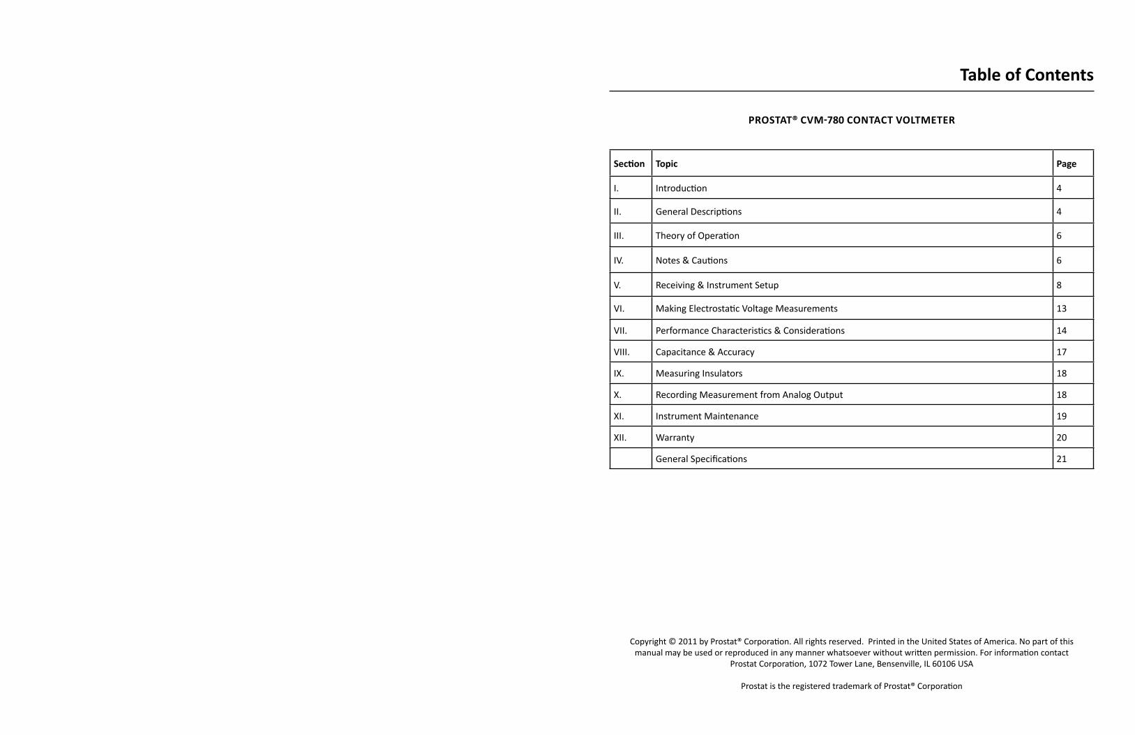
Section Topic Page
I. Introduction 4
II. General Descriptions 4
III. Theory of Operation 6
IV. Notes & Cautions 6
V. Receiving & Instrument Setup 8
VI. Making Electrostatic Voltage Measurements 13
VII. Performance Characteristics & Considerations 14
VIII. Capacitance & Accuracy 17
IX. Measuring Insulators 18
X. Recording Measurement from Analog Output 18
XI. Instrument Maintenance 19
XII. Warranty 20
General Specifications 21
Table of contents
Copyright © 2011 by Prostat® Corporation. All rights reserved. Printed in the United States of America. No part of this manual may be used or reproduced in any manner whatsoever without written permission. For information contact
Prostat Corporation, 1072 Tower Lane, Bensenville, IL 60106 USA
Prostat is the registered trademark of Prostat® Corporation

4 Rev. B / March 2012 5Rev. B / March 2012
CVM-780 Contact Voltmeter CVM-780 Contact Voltmeter
I. Introduction
The Prostat CVM-780 is a portable high impedance voltmeter with an active probe system used for locating and measuring electrostatic potentials on conductors and other materials. Its intended purpose is to determine voltages on critical conductors such as devices and assemblies in electronics industry manufacturing and test environ-ments. It is indispensible for
• Analyzing the electronic manufacturing/test/repair process to determine levels of protection for ESD sensitive devices from Machine Model (MM) and Charge Device Model (CDM) damage, and
• Locating cause(s) of ESD failures.
• Measuring voltages on devices, subassemblies, assembly equipment, fixtures, automatic test fixtures, tools, chassis, mobile equipment, dissipative materials, etc.
The CVM-780 Contact Voltmeter™ combines the ease of use of a digital voltmeter with the high input im-pedance and low input capacitance of a true electrostatic voltmeter in a small, portable, battery operated package. The contact probe enables you to measure voltages with pinpoint accuracy. Ceramic Probe Tips allow accurate measurement without significant ESD or RF generation. Robust metal tips are supplied for general audit and equipment measurements.
Being a true electrostatic voltmeter, not a field meter means that the CVM-780 reads real voltage, without confusing it with electrostatic field strength, which can be distinctly different. The CVM-780 uses a unique active probe design which is fully guarded and shielded for minimal interference with the surrounding E field. The CVM-780 is powered by rechargeable Nickel Metal Hydride batteries; a compact universal bat-tery charger is supplied for international use. Properly used, the CVM-780 Contact Voltmeter will become one of your most valuable portable ESD Analysis tools.
II. General Descriptions The CVM-780 features a large easy to read LED display, analog output, and rechargeable battery in a shock absorbent package, and a specially designed active probe assembly.
A. The probe assembly is connected to the CVM-780 case using a supplied 6-foot DB9 cable
B. Ceramic or metal probe tips are used to make direct contact with objects and surfaces under test. Voltage is shared with the probe assembly, the measurement is calculated, and shown on the LED display
ImPORTAnT nOTeCeramic tips are fragile and used for direct contact with ESD sen-sitive devices and assemblies. Metal tips are robust and used to measure equipment, fixtures, tools and other non-ESD sensitive
elements.
C. Connect the CVM-780 to a previously tested ground to provide a defined reference for accurate measurements
D. CVM-780 intended measurement range is 0 - 525 volts in one volt increments. All measurements are immediately shown in the 3 digit LED display. Polarity switching during measurements is automatic
E. The round brass front panel ground plate is used as a zero reference for the instrument. Between measurements the probe
tip (ceramic or metal pin) is placed in contact with the ground plate to confirm the probe tip’s zero voltage as displayed on the panel LED. Instrument zero is adjusted using the manual adjust-ment provided below the LED display.
F. An analog output mini-jack receptacle is provided for monitoring or recording CVM-780 measure-ments. The analog output jack provides an output of 0.1 millivolt for each 1.0 volt measured by the CVM-780. The output is independent of the meter indication to maximize response time. The output is compatible with the PROSTAT PGA-710 AutoAnalysis System.
G. A universal AC/DC battery charger is provided for charging the AA sized Metal Hydride recharge-able batteries. Battery life is approximately 3.5 hours. Fully charged batteries should provide a full day of measurements if the unit is turned OFF when not in use.

6 Rev. B / March 2012 7Rev. B / March 2012
CVM-780 Contact Voltmeter CVM-780 Contact Voltmeter
H. A small tip replacement tool is supplied to prevent probe and tip damage when exchanging tips. The tip should never be over tightened
I. An outer removable rubber boot reduces mechanical shock during portable operations and provides an easel stand during use.
J. few alcohol prep wipes are included to periodically clean the black insulator mounted at the front of the probe assembly. The wipe may be used to clean the probe and instrument cases. DO nOT USe the alcohol wipes on the display LED.
III. Theory of Operation
The CVM-780 operation is quite unique.
A. As the probe tip of the CVM-780 approaches a charged conductor it senses the conductor’s charge. The tip is driven by the probe to match the conductor’s polarity and increases tip voltage as its distance to the conductor decreases.
B. While tip voltage continues to increase as it approaches the charged conductor, the CVM-780 probe tip does not reach the conductor’s full voltage until it physically contacts the charged con-ductor.
C. At the moment of contact a small transfer of electrons occurs from the conductor to the CVM-780 tip that completes the measurement. The probe tip voltage will be well within
1. 5% of the conductor’s original voltage, ±2 counts from ±25 to ±525 volts, and2. Within 10% ±2 counts at <±25 volt measurements.
Therefore the change in conductor voltage at moment of tip contact is very small.
D. Though very small electron transfer occurs at moment of contact, there is no measureable “ESD” event when employing ceramic tips. The small amount of electron transfer is controlled by both tip and probe design. Also, there is no significant RF generated because the electron transfer is small and “relatively slow” to avoid a discharge event.
E. The resulting measurement accuracy depends on the actual voltage of the conductor, the length and types of probe tips, and the influences in the measurement environment. Environmental influences include presence and movement of objects and bodies, ambient conditions, and size of objects and their distance to ground (Capacitance).
IV. notes & cautions
The CVM-780 is a precision instrument designed to measure electrostatic DC voltage.
• Do not use the instrument or probe assembly for AC measurement applications• Do not expose the instrument it to shock or excessive moisture. • Use good measurement practices at all times.
Warranty is vOID if either the instrument case or probe assembly are opened or misused. There are no user adjustments inside the instrument or probe assembly. Contact Prostat Corporation for service, fur-ther information and operational suggestions
WARnInGHIGH vOlTAGe: Internal instrument and probe voltage can exceed ±575 volts.
• DO nOT OPen the instrument case or probe assembly as painful personal shock may occur.
• DO nOT InSeRT meTAl OBJecTS into instrument connectors • DO nOT cOnnecT any unauthorized instrument, fixture or device to the
CVM-780 instrument or probe assembly as permanent equipment damage and, or an unsafe condition may occur.
• DO nOT USe In FlAmmABle OR cOmBUSTABle envIROnmenTS when metal probe tip is installed
cAUTIOn: The CVM-780 probe assembly uses very sharp pin-like ceramic and metal tips for measure-ments that will cause painful and possibly serious injury if not handled with care.
• Keep probe tip covered with supplied probe tip cover when not in actual use.• Store reserve tips in supplied foam lined plastic accessories case• DO NOT make contact to people with ceramic or metal pin tips; REMOVE pin tips when making
personnel measurements
cAUTIOn: The CVM-780 instrument is designed to measure electrostatic voltage on objects; Do not mea-sure Ac energized circuits with this instrument
cAUTIOn: The operator is grounded during normal operations while holding the probe assembly. Do not make contact with, or touch energized AC circuits with your free hand or the probe tip assembly
cAUTIOn: This instrument is not intended for use in flammable or combustible environments
nOTe: Ceramic and metal measurement tips are supplied with this instrument. Tips are costly to replace and may be easily damaged. Handle them with care; store them in the supplied accessory box.
ceramic & metal probe tips are not covered by warranty. Lost or damaged tips can be replaced by con-tacting your Authorized PROSTAT Reseller.
nOTe: The CVM-780 must be connected to an approved ground for proper operation and accurate mea-surements
nOTe: The CVM-780 is powered by rechargeable metal hydride batteries. Dispose of depleted batteries in a safe manner and in accordance with local laws and ordinance.
nOTe: DO NOT OPEN the instrument or probe assembly. There are no customer serviceable parts or ad-justments inside the instrument package or probe assembly.
The CVM-780 has been in test and use for over 2 years prior to manufacture for general ESD applications.
8 Rev. B / March 2012 9Rev. B / March 2012
CVM-780 Contact Voltmeter CVM-780 Contact Voltmeter
It has proven itself reliable and quite stable. The customer should have few if any problems with this unique instrument. If after examining this manual and you have questions, contact Prostat or its Autho-rized Resellers for assistance. See the “Warranty” section later in this document for detailed information regarding further coverage and support.
Prostat Corporation assumes no liability in the event of instrument misuse, ignoring above Notes, CAU-TION’s and WARNING’s. Should the instrument be opened or serviced by unauthorized personnel or dam-aged by misuse, all liability, repair, replacement and freight costs are the customer’s responsibility.
V. Receiving & Instrument Setup
The CVM-780 meter assembly, probe and accessories set is shipped in foam lined shipping package and includes the following items:
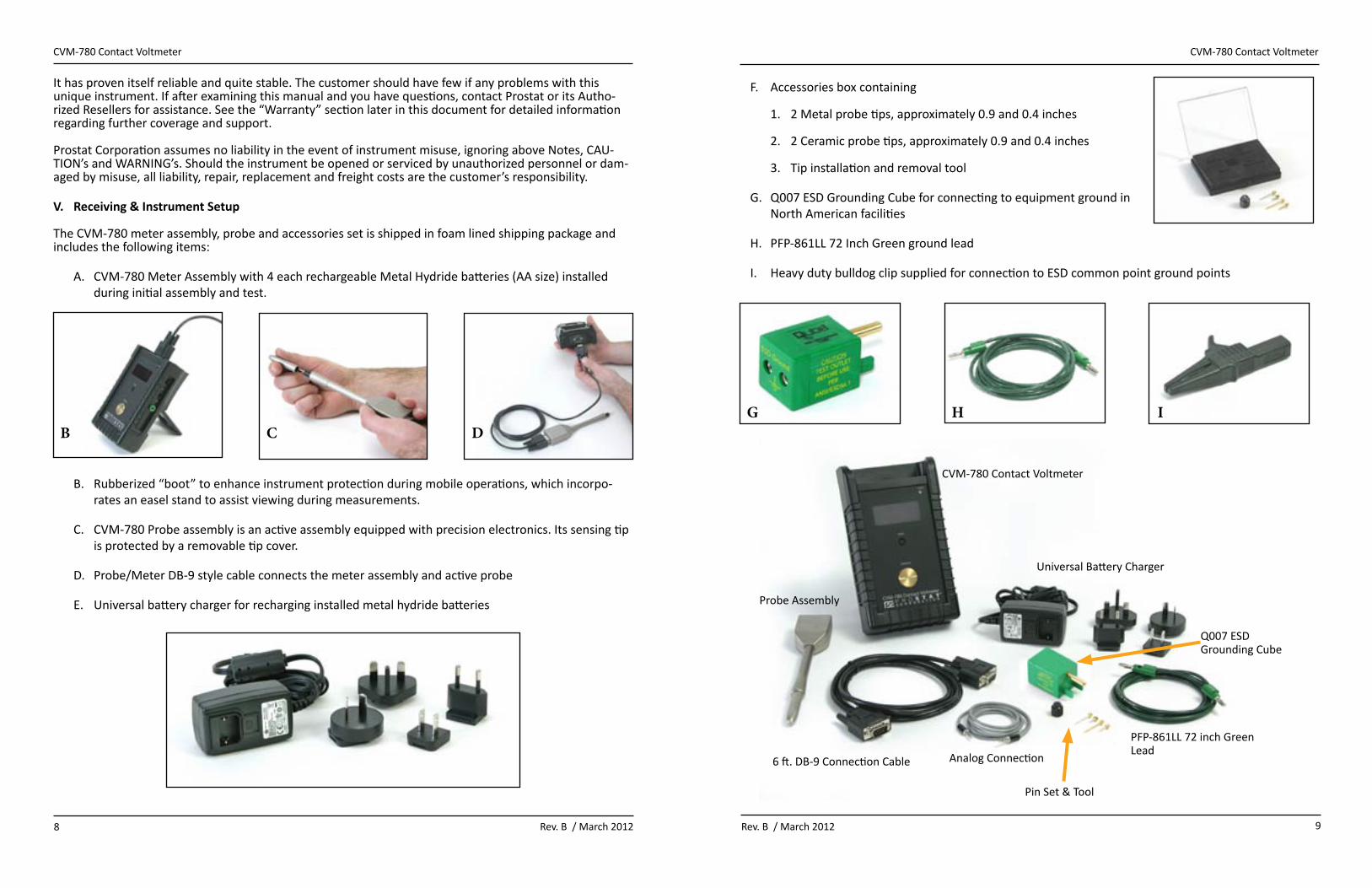
A. CVM-780 Meter Assembly with 4 each rechargeable Metal Hydride batteries (AA size) installed during initial assembly and test.
B. Rubberized “boot” to enhance instrument protection during mobile operations, which incorpo-rates an easel stand to assist viewing during measurements.
C. CVM-780 Probe assembly is an active assembly equipped with precision electronics. Its sensing tip is protected by a removable tip cover.
D. Probe/Meter DB-9 style cable connects the meter assembly and active probe
E. Universal battery charger for recharging installed metal hydride batteries
F. Accessories box containing
1. 2 Metal probe tips, approximately 0.9 and 0.4 inches
2. 2 Ceramic probe tips, approximately 0.9 and 0.4 inches
3. Tip installation and removal tool
G. Q007 ESD Grounding Cube for connecting to equipment ground in North American facilities
H. PFP-861LL 72 Inch Green ground lead
I. Heavy duty bulldog clip supplied for connection to ESD common point ground points
CVM-780 Contact Voltmeter
Probe Assembly
6 ft. DB-9 Connection Cable
Q007 ESD Grounding Cube
Universal Battery Charger
PFP-861LL 72 inch Green Lead
Pin Set & Tool
B C DG H I
Analog Connection
10 Rev. B / March 2012 11Rev. B / March 2012
CVM-780 Contact Voltmeter CVM-780 Contact Voltmeter
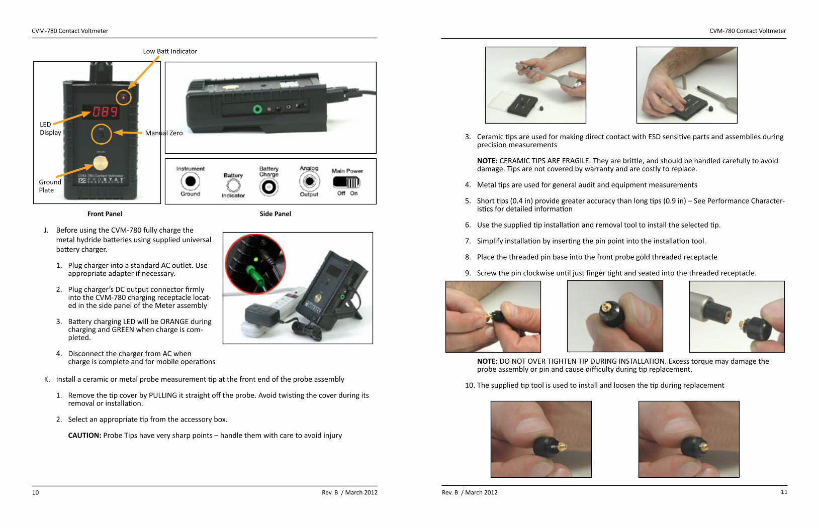
Front Panel Side Panel
Low Batt Indicator
Manual ZeroLED Display
Ground Plate
J. Before using the CVM-780 fully charge the metal hydride batteries using supplied universal battery charger.
1. Plug charger into a standard AC outlet. Use appropriate adapter if necessary.
2. Plug charger’s DC output connector firmly into the CVM-780 charging receptacle locat-ed in the side panel of the Meter assembly
3. Battery charging LED will be ORANGE during charging and GREEN when charge is com-pleted.
4. Disconnect the charger from AC when charge is complete and for mobile operations
K. Install a ceramic or metal probe measurement tip at the front end of the probe assembly
1. Remove the tip cover by PULLING it straight off the probe. Avoid twisting the cover during its removal or installation.
2. Select an appropriate tip from the accessory box. cAUTIOn: Probe Tips have very sharp points – handle them with care to avoid injury
3. Ceramic tips are used for making direct contact with ESD sensitive parts and assemblies during precision measurements nOTe: CERAMIC TIPS ARE FRAGILE. They are brittle, and should be handled carefully to avoid damage. Tips are not covered by warranty and are costly to replace.
4. Metal tips are used for general audit and equipment measurements
5. Short tips (0.4 in) provide greater accuracy than long tips (0.9 in) – See Performance Character-istics for detailed information
6. Use the supplied tip installation and removal tool to install the selected tip.
7. Simplify installation by inserting the pin point into the installation tool.
8. Place the threaded pin base into the front probe gold threaded receptacle
9. Screw the pin clockwise until just finger tight and seated into the threaded receptacle.
nOTe: DO NOT OVER TIGHTEN TIP DURING INSTALLATION. Excess torque may damage the probe assembly or pin and cause difficulty during tip replacement.
10. The supplied tip tool is used to install and loosen the tip during replacement

12 Rev. B / March 2012 13Rev. B / March 2012
CVM-780 Contact Voltmeter CVM-780 Contact Voltmeter
11. Always replace probe tip cover to prevent damage to tips and to avoid personal injury when
a. probe is not actually in useb. during transportc. While in storage.
L. Connect the Probe and Meter assemblies using the DB-9 cable
a. Carefully insert the 9 pin cable/meter connectors to the meter front end panel and to the probe connection box. Secure them in position with the installed thumb screws. Do not over tighten.
b. Insure the DB-9 cable is not twisted or kinked
cAUTIOn: Avoid tangling or catching the cable on foreign or moving objects during use
M. Connect the CVM-780 to an earth ground
a. Insert the Green ground wire banana in the green Ground receptacle located on the side panel of the Meter assem-bly.
b. Connect the free end of the ground wire to ground using the supplied grounding block or alligator clip
nOTe: the CVM-780 must be connected to an approved ground for proper operation and accurate measurements
cAUTIOn: Avoid tangling or catching the ground wire on foreign OR MOVING objects during use
cAUTIOn: The operator is grounded during normal operations while holding the probe assembly. Do not make contact with, or touch energized circuits with your free hand or the probe tip assembly
VI. making electrostatic voltage measurements
The CVM-780 is designed to measure electrostatic voltage on conductors without discharging the object in question. When using metal probe tips, a slight voltage differential during metal to metal contact will cause low level ESD and RFI generation. When using a ceramic probe tip small ESD events and low level RFI generation are avoided. Use the following guidelines for making measurements on conductors. These procedures assume the above receiving and setup steps above are completed, and all cautions and warn-ings are followed.
1. Release the easel stand at the back of the unit and stand the CVM in a semi vertical position. Place the instrument on a stable platform, or hand hold the instrument with the easel retracted
2. Locate the power switch on the side panel and slide it toward the meter’s front end to the ON position.
a. The front panel LED display will illuminate
b. The instrument is energized for operation
3. Remove the probe tip cover by pulling it straight off. Do not twist the cover unnecessarily.
4. Place the probe tip in direct contact with the round brass ground plate on the instrument’s front panel
a. The LED should indicate 000
b. To adjust LED indication while the probe is grounded, turn the slotted Manual Zero knob until the LED indicates 000 nOTe: Ground the tip using this procedure between measurements
OPeRATIOnAl nOTeWhen the probe tip is not in contact with ground or making a defined measurement,
the measurement system is “floating”. When floating free of a contact measurement any indicated displayed voltage is normal and not meaningful. (See Instrument
Maintenance, below.)

14 Rev. B / March 2012 15Rev. B / March 2012
CVM-780 Contact Voltmeter CVM-780 Contact Voltmeter
5. Once the probe is zeroed touch the tip to the conductive ob-ject being measured
a. Hold the probe steady with slight pressure on the tip. Avoid tip damage, DO nOT APPlY eXceSSIve PReSSURe TO THe TIP
b. The voltage measurement will be seen on the front panel LED display
c. Indicated voltage will stabilize quickly, usually within 2 to 5 seconds
d. Should changes in displayed voltage occur during measurement they are typically due to:
i. Natural ionization of the electrostatic charge to airii. The effect of nearby ionizationiii. Capacitive coupling with moving objects and personnel nearbyiv. Charging or Discharge of the conductive object being measured by means other than
the CVM-780 measurement
6. Ground probe tip to the front panel ground plate between measurements
7. Turn the CVM-780 power switch to OFF when instru-ment is not in use, and replace probe tip cover
8. If Low Batt LED on front panel illuminates, recharge the unit’s batteries. note: The CVM-780 may be used for measurements during charging. However, as battery voltage will be changing during the charge be sure to ground and re-zero the probe tip between measurements.
VII. Performance characteristics & considerations
While CVM-780 measurements are easily performed, one should develop and practice a consistent tech-nique to make accurate measurements with the CVM-780. Grounding the instrument is important for accurate results because “ground” is the instrument’s zero reference for its measurement circuit.
The CVM-780 probe is “active”. Its internal components assess tip voltage as it approaches a charged conductor. It communicates with the instrument package to increase, and provide similar tip voltage upon contact with the conductor being measured. The front panel LED displays tip voltage measurements upon contact with an object or material.
Once the measurement is obtained, separation from the conductor being measured does not reset the probe to zero. In effect it remains at a similar voltage as the last measurement, or may “float”. Grounding the tip between measurements resets the system to zero as can be seen of the front panel LED display.
nOTeWhen the probe tip is not in contact with ground or making a defined measurement, the measurement system is “floating”. When floating free of a contact measurement any indi-cated displayed voltage is not meaningful. (See Instrument Maintenance, below.)
Tip Selection
Tip selection is a matter of practicality, but will influence measurement ac-curacy. Typical measurement error is quite small regardless of tip selection:
≤ ±5%, ±2 Counts from ±25 to ±525 Volts ≤ ±10%, ±2 Counts from 0 to ± 25 Volts
However, performance accuracy will vary within these tolerances depending on tip material and tip length. Comparative measurements indicate the fol-lowing general guidelines for tip performance. Metal Tips Largest deviation from reference Small ESD/RFICeramic Tips Smallest deviation from reference No ESD/RFILong Tips (0.9 – 1.3”) Largest deviation from referenceShort Tips (0.4 – 0.6”) Smallest deviation from reference
Consequently, the least accurate tip is a long metal tip; while the most accurate is a short ceramic tip. In all cases, accuracy will also vary based on technique, ambient conditions, ground reference quality and other variables discussed below.
Measurement Error
When measuring a constant, precision DC voltage reference, error is typically 1 volt or less, but always equal to or less than ±2 volts. The circuit is capable of measuring the instrument’s entire voltage range, as follows:
ITem no. TARGeT 1A 500 V ≤ ±2 V2A 100 V ≤ ±2 V3A 50 V ≤ ±2 V1B 10 V ≤ ±1 V
This procedure confirms the ability of the CVM-780 to measure DC voltage accurately, as would be ex-pected of any good quality DC voltmeter. Variables within the error range are usually attributed to manual zeroing of the instrument to ground. Indication of practical measurement performance error in process applications is a different matter and most important.
There are many variables in the manufacturing environment that will influence measurement perfor-mance of a contact voltmeter. To minimize those variables and estimate instrument measurement er-ror, contact measurement of a charged precision 20 pF capacitor is made while the capacitor’s voltage is monitored by a second high impedance contact voltmeter. The procedure creates a stable contact voltage measurement situation, as follows:

16 Rev. B / March 2012 17Rev. B / March 2012
CVM-780 Contact Voltmeter CVM-780 Contact Voltmeter
1. A 20pF is placed on a ground plane and a high impedance contact voltage probe connected to its charging conductor.
2. The capacitor is charged to a defined voltage using a precision DC voltage supply.
3. The CVM-780 under test is grounded and its probe zeroed.
4. The capacitor’s charged conductor is measured with the CVM-780 under test.
5. The CVM-780’s measurement deviation from the (a) initial capacitor’s reference voltage before contact by the CVM under test and (b) the installed voltage monitor after test are recorded.
6. The data is then used to calculate the capacitor’s voltage change due to the measurement and any deviation seen between the installed reference instrument and the unit under test.
Typical measurement deviation is summarized below.
Performance measurements using Reference 20pF capacitor
ITem no. % Dev. FROm InITIAl cAPAcI-TOR vOlTAGe
TeST UnIT Dev FROm 2nd mOnITOR cvm
1C 450 - 525 V <±5% ±2 Counts ≤ ±2 Volts2C 75 - 150 V <±5% ±2 Counts ≤ ±2 Volts3C 40 - 65 V <±5% ±2 Counts ≤ ±2 Volts4C <25 V <±10% ±2 Counts ≤ ±2 Volts
In the Performance Measurements table, above, the % DEV. FROM INITIAL CAPACITOR VOLTAGE is the to-tal voltage change of the charged, monitored capacitor when the CVM under test makes contact with the reference capacitor’s conductor. At the moment of contact by the CVM under test, the reference capacitor system voltage changes slightly. The percent change from the capacitor’s initial voltage is based on a com-bination of two elements (a) the additional capacitance of the probe assembly tip to that of the floating capacitor and (b) some inevitable electron transfer between the capacitor conductor and the probe tip.
The instrument monitoring the capacitor and the CVM-780 under test are both high impedance contact voltmeters with very low capacitive loading on the measurement. Consequently, if well zeroed and prop-erly grounded they should each measure the same voltage on the capacitor after contact of the CVM-780.under test. Any error would be that of operator zero adjustment and ground anomalies. Thus a 2 volt or less difference between the two voltmeters would be considered acceptable.
Note that the precision reference capacitor is used to confirm CVM-780 performance by providing a stable voltage platform. The use of charge plate monitors in CVM-780 performance testing is avoided be-cause (a) while total CPM capacitance changes at the moment of probe contact, (b) total CPM capacitance varies dramatically with its design and surroundings, including the operator and other moving objects in the vicinity. Using a reference capacitor minimizes these measurement variables.
Thus, in real world the accuracy of practical CVM-780 measurements of a conductive object are based on:
• The object’s capacitance and charge in combination with • The probe assembly’s capacitance • Ambient conditions• Process dynamics • The small transfer of electrons between the probe tip and the object under test
Understanding these variables and the process conditions heightens the value of the operator’s measure-ments.
Metal Tips
Metal tips are far more robust than ceramic materials and less prone to damage. These tips are provided for general audit and analysis measurements of equipment, chairs, carts, material handling items, tools, fixtures, etc. where many voltage measurements may be required, but close tolerance accuracy, minor voltage discharge and low level RF generation are not major factors. Metal tips should be used in these applications to minimize use and potential damage to ceramic tips.
Note that when using metal tips to measure conductors the slight differential voltage between the tip and the conductor at the moment of contact will result in some electron transfer. This, in turn, creates a very small ESD event, and results in low level RFI signal being generated. These events are not harmful in all but the most sensitive environments, are difficult to see and usually not measureable in most applica-tions. However, this is why metal tips are recommend for general audit measurements and ceramic tips for ESD sensitive device and assembly measurements.
Ceramic Tips
Ceramic tips provide the most accurate contact voltage measurements, and do so without causing a mea-sureable ESD event or the resulting generation of RFI. These materials are compounded and formed to provide a controlled transfer of electrons upon contact with a conductive object. They are ideal for direct contact measurement of ESD sensitive devices and assemblies, or in areas and situations where any ESD or RFI may pose a problem.
Unfortunately, the ceramic tips are fragile, quite brittle and can be easily damaged if one is not careful. In addition, replacements are costly. When making general measurements use the metal tips and preserve your expensive ceramic tips for critical device and assembly applications.
VIII. capacitance & Accuracy
Actual accuracy is dependent on the user’s steady and reproducible technique, and environmental dy-namics. In particular, capacitance (C) of the item being measured relative to ground and other nearby objects. This is based on
Q = CVAnd, Q = V CWhere,
Q = Charge on the objectC = Capacitance of the item under test related to its size and distance to ground and other objectsV = Resulting voltage on object
Thus, any nearby movement of equipment components, personnel or objects may influence the item under test’s capacitance and subsequently its voltage. In a relatively non-dynamic environment measure-ments are very accurate and stable. As a guideline, define the measurement environment as the operator and objects within 1 to 2 feet of the item being measured.
The effect of capacitance can be easily demonstrated. Apply voltage to the floating plate of a Charge Plate Monitor (CPM). A standard six inch CPM will have a capacitance of approximately 20pF. While observing the CPM’s plate voltage move your hand slowly back and forth near the surface of the floating plate. If

18 Rev. B / March 2012 19Rev. B / March 2012
CVM-780 Contact Voltmeter CVM-780 Contact Voltmeter
you are grounded your capacitance will cause voltage measurement variance as your hand approaches, and then leaves the CPM’s immediate vicinity. If you are ungrounded, your combined body charge, field and capacitance will have a significant impact on the plate’s measurement. Repeat the measurement while measuring the approximate voltage of the CPM floating plate with the CVM-780. You will see a simi-lar shift in voltage as someone else’s hand approaches, and then leaves the vicinity of CPM’s surface.
The relationship of Charge (Q), Capacitance (C) and Voltage (V) is the essence of electrostatic measure-ment and analysis. Prostat uses this relationship to assess CVM-780 accuracy and performance.
IX. measuring Insulators
Insulators are very difficult to measure accurately as almost every charge combination may be on the material’s surface in immediate proximity to each other. When using a field meter, one typically sees the strongest field polarity although both positive and negative charges may reside on the surface.
The CVM-780 is not designed to provide accurate and repeatable measurements of insulators. It will mea-sure the voltage at the point of contact with an insulator. One might consider this an indication of voltage, but not an exact material measurement. Unfortunately once the tip makes contact and separates from the surface after the measurement, a new charge is triboelectrically generated at that point, and that spot’s voltage will be changed. Thus, the measurement is only an approximate indication of surface voltage at a point and is not repeatable.
X. Recording measurement from Analog Output
The CVM-780 may be used to record indicated voltage with the PROSTAT PGA-710 AutoAnalysis System™, or similar recording device. Be sure to zero both the CVM-780 and the recording device at the same time.
When using the PGA-710, follow these steps.
A. Start the PGA-710 Software on your computer, connect the PGA-710 and energize the operating system
B. In the PGA-710 Software:
1. Select the EDIT dropdown menu
2. Open the Current Measures window
C. Connect the PGA-710 supplied analog cable to the CVM-780 and PGA-710
D. Setup, ground and energize the CVM-780
E. Place the CVM probe assembly tip against the front panel ground plate and adjust its approximate zero point.
F. Click the PGA-710 Preview button to start the graph display operation.
G. Compare the CVM’s LED displayed voltage with the voltage displayed in the Current Measures window of the 710 screen.
1. If the PGA-710 and CVM-780 zero setting are the same measurement recordings can be made
2. If they are not the same, stop the Preview and proceed as follows.
H. Adjust the CVM carefully to display 000 on its LED.
I. Select the PGA-710 EDIT drop down menu and open the Device Control window. In the Voltage section:
a. Click clear Zero button, thenb. Click Set Zero button, thenc. Click Done button to close the window and active the zero reset
J. Start the PGA-710 Preview and compare the Currant Measures Voltage to the CVM-780’s LED volt-age; they should both be 000 ±1 volt.
As measured voltage increases, there is a small deviation between CVM-780 displayed voltage and PGA-710 recorded voltage. It may be as low as ±2 volts below ±200 volts and increase to 5 or 6 volts deviation at ±500 volts. The fact that the measurement can be made relatively accurately at that level is significant; the 5 to 6 volts deviation is generally not an important error.
XI. Instrument maintenance
Maintenance tips and care of the CVM-780 follow.
A. There are no user adjustments or maintenance items inside the instrument case or probe assem-bly. Do not open the case or probe as this will damage the instrument and VOID its warranty. War-ranty seals are a reminder not to open these units.
B. Clean the surfaces of the instrument case and probe assembly with a low linting, non-abrasive cloth lightly dampened with 70% solution of alcohol and 30% water.
C. It is important to keep the front probe assembly black insulator very clean. Surface contaminants on this insulator will cause voltage leakage to the probe’s grounded metal surface resulting in unstable measurements. Use a low linting, non-abrasive cloth lightly dampened with 70% solution of alcohol and 30% water to clean the insulator. Alcohol prep wipes are useful for removing finger oils and contaminants.
D. Excessive voltage drift while the probe is “floating” – that is, while not grounded or making a contact measurement – may be caused by a large charge on the black insulator used for probe tip mounting. Insulator surface charge is caused by installing and removing the probe tip cover. Exces-sive “twisting” of the tip cover increases this charge. This charge does not affect instrument ac-curacy, but may become distracting. If desired remove this charge by exposing the probe assembly to a balanced bench top ionizer. Note that the ionizer’s offset voltage (unbalance) will be displayed on the CVM-780’s LED.

20 Rev. B / March 2012 21Rev. B / March 2012
CVM-780 Contact Voltmeter CVM-780 Contact Voltmeter
E. Store the CVM-780 in a clean, dry environment with the tip cover installed. For long term storage, remove the Metal Hydride batteries.
F. Replacement Metal Hydride AA size rechargeable batteries are readily available in retail stores and from electrical suppliers. Do not use any other rechargeable battery in your CVM-780.
WARnInGThe CVM-780’s battery recharging circuit is designed for the specified Metal Hydride batter-
ies. Use of any other battery with the CVM battery circuit and recharger may damage the instrument, can be unsafe by causing overheating and possibly fire, which will also void the
instrument’s warranty.
Do not expose the instrument or probe assembly to excessive shock or vibration. The rubberized protec-tive boot is intended to minimize mechanical shock and damage. However, it is not a substitute for care-ful handling.
XII. Warranty
Prostat Warranty
Prostat Corporation expressly warrants that for a period of one (1) year from the date of purchase, that Prostat instruments will be free from defects in material (parts) and workmanship (labor). If PROSTAT receives notice of such defect during the warranty period, Prostat will replace at its expense such parts that it determines to be defective. Any defective part must be returned to PROSTAT postage prepaid with proof of purchase date.
Warranty Exclusions – THE FOREGOING EXPRESS WARRANTY IS MADE IN LIEU OF ALL OTHER PRODUCT WARRANTIES, EXPRESS AND IMPLIED, INCLUDING MERCHANTABILITY AND FITNESS FOR A PARTICULAR PURPOSE, WHICH ARE SPECIFICALLY DISCLAIMED. The express warranty will not apply to defects or dam-age due to accidents, neglect, misuse, alterations, operator error, or failure to properly maintain, clean, or repair products. Limit of Liability – in no event will Prostat or any seller be responsible or liable for special, incidental, or consequential losses or damages, under any legal theory including but not limited to contract, negligence, or strict liability.
Fulfillment by Prostat of its express warranty obligations described above will be purchaser’s exclusive remedy and will be Prostat’s and seller’s limit of liability for any breach of warranty or otherwise.
cvm-780 contact voltmeter Specifications
Basic Description: High impedance contact voltmeter with active probe
DC Characteristics: Intended Operating Range: 0 to ±525 volts Resolution: 1 volt, 3 digit display Circuit accuracy: <±1% note: Maximum measurement range is ±575 Volts for brief periods
Dynamic Characteristics: Response Time: Approximately 1ms for a voltage step of 200V at the probe tip to the monitor output. Digital display update: 3 readings per second.
Input charge/measurement: Approximately 100 femptocoulomb/volt (1.0x10⁻¹³ C/V)
Input Impedance: ≥1014 ohm in parallel with <1pF Capacitance
Monitor Output: Scale Factor: 10,000:1; 100uV/V (Compatible with Prostat™ PGA-710 Autoanalysis System™) Recording Deviation: Typically < ±10 volts at ± 500 Volts
Measurement Tolerances: When measuring DC voltage reference500 V ≤±2 V100 V ≤±2 V50 V ≤±2 V10 V ≤±1 V
When measuring floating conductors 500 V ≤±5% ±2 Counts100 V ≤±5% ±2 Counts50 V ≤±5% ±2 Counts
10 V ≤±10% ±2 Counts
Probe Tips: Metal: Nominally 0.95 and 0.45 inch Ceramic 0.90 and 0.40 inch ±0.05”
Portable Operation: Approximately 3.5 Hours on Full Battery Charge (Operates during Battery Charge)
Power: 4 each Energizer NH15-2500 Nickel-Metal Hydride rechargeable batteries (AA Size)
Charger: Universal 90 to 264 Volts, 47 to 63 Hz
Meter Dimension 6.5 in (16.5 cm) L x 4.25 in (10.8 cm) W x 1.57 in (4.0 cm) H(without boot):
Meter Dimension 7.5 in (19.1 cm) L x 4.25 in (10.8 cm) W x 2.36 in (6.0 cm) H(with boot):
Probe Dimension: 8.9 in (22.5 cm) L x 1.5 in (3.7 cm) W x 0.78 in (2.0 cm) H
Meter Weight: 1.5 lbs, with boot
Probe Weight: 3.6 oz

nOTeS nOTeS
22 Rev. B / March 2012 23Rev. B / March 2012
CVM-780 Contact Voltmeter CVM-780 Contact Voltmeter

nOTeS nOTeS
24 Rev. B / March 2012 25Rev. B / March 2012
CVM-780 Contact Voltmeter CVM-780 Contact Voltmeter

nOTeS
26 Rev. B / March 2012
CVM-780 Contact Voltmeter

P R O F E S S I O N A L S T A T I C C O N T R O L P R O D U C T S
Corporate Headquarters • 1072 Tower Lane • Bensenville, IL 60106 • 630-238-8883 • Fax: 630-238-9717 • 1-855-STATIC1 • www.prostatcorp.comProstat Corporation
Specifications are subject to change without notice.All Prostat trademarks and trade names are the property of Prostat Corporation.
All other trademarks and trade names are the property of their respective companies.