bipolar nickel metal hydride battery development and testing 2006... · bipolar nickel metal...
TRANSCRIPT

Bipolar Nickel Metal Hydride Battery Development and Testing
DOE ENERGY STORAGE SYSTEMS RESEARCH PROGRAM
ANNUAL PEER REVIEWNovember 2 – 3, 2006, Washington, D.C.
James Landi [email protected]

Program Objectives and Benefits
The objective of this program is to further develop the bipolar NiMH battery design to be used in high-energy and high-power energy storage applications.
– Build and demonstrate large-format batteries– Demonstrate these batteries in present and future applications
The bipolar NiMH battery could provide the following benefits: – Improve efficiencies by reducing transmission peaking losses
and shifting peak demands. – Reduce power and voltage sag to users.– Provide an efficient method to distribute backup energy/power
for utilities to ensure uninterruptible service to their customers. – Increase reliability of solar and wind systems that require energy
storage.

Program History
This program commenced September 2005, and is a continuation of previous development and demonstration programs.
Previous Accomplishments– Built and delivered a 600 V, 35 kWh, 20 kW Inverter battery system
Effort was in collaboration with First Energy Testing done by EPRI Solutions in Knoxville, TN
– Built a 500 V, 100 kVA UPS battery system, replacing ultra-capacitors– Built and delivered a 48 V, 50 Ah battery for a 3 kW UPS system– Successfully demonstrated a high power 40 kW, 350 V battery module
Present Program Milestones– Market Assessment– Design and Performance Improvements– System Builds and Demonstrations

EEI’s Bipolar Wafer Cell Battery Design
– Current flows perpendicular to all electrode surfaces
– Active materials are efficiently utilized, minimizing internal resistance
– Flexible form factor – 25% higher power– 25% less volume– 25% lower manufacturing cost– Environmentally friendly– Excellent life
8

Two Bipolar NiMH Battery TypesHigh Energy NiMH Thicker/higher capacity electrodes
– High Energy/Lower power per unit weight and volume >50 Wh/kg, >140 Wh/L 35 W/kg, 100 W/L – Continuous
12 V to >600 V systems
High Power Applications Thinner/lower capacity electrodes High power/Lower energy per unit weight and volume
– >1 kW/kg, >2.6 kW/L - <10 second pulse– >30 Wh/kg, >80 Wh/L
12 V to >700 V systems

Electro Energy’s Market Assessment of High Power and High Energy Storage
EEI is conducting an ongoing market assessment to identify opportunities and pilot demonstrations for the bipolar batteries
Three market segments identified as prime candidates for bipolar battery applications– Electric Utilities– Critical Infrastructure Service Providers– Multi-Tenant Buildings
Energy storage solutions have two significant hurdles to overcome:– Education: Understanding the benefits associated with batteries– Investment: The economics of battery technology remains a
barrier

Design Improvements
Optimized negative-to-positive ratio resulting in improved performance and increased cycle life.
Improved electrode production processes– Established a continuous nickel foam based production process
for energy cells– Developed in-house capability to produce hydride electrodes for
energy cells– Developed a thin coating process for nickel and hydride
electrodes for power cells Implemented an automatic electrolyte filling process Developed and implemented a sealed stack formation process Investigated alternate materials leading to cost reductions

Cell Balancing System EEI has been utilizing a commercial cell balancing system to balance
every 5, 10, 15, 20, or 30 cells in battery systems Results in improved capacity, reduced heat, and increased efficiency
EEI 40 Cell Module Testing (Capacities With and Without Balancing System
-
2.0
4.0
6.0
8.0
10.0
12.0
14.0
16.0
18.0
20.0
22.0
1 2 3 4 5 6 7 8 9 10 11 12 13 14 15
Cycle
Cap
acity
(Ah)
Charge_Capacity Discharge_Capacity
EEI 20 Cell Module (Capacities With and Without Balancing System)
0
2
4
6
8
10
12
14
16
18
20
0 1 2 3 4 5 6 7 8
Cycle #
Cap
acity
(Ah)
Discharge_Capacity(Ah)
Typical Pack Shows Greater than 5% Capacity Increase
Severely Unbalanced Pack Shows 100% Capacity Increase

EEI 4 kW Inverter Peak Shaving/Back-Up System
•4 kW Inverter
•1.5 kW Generator
•3 – 1 kWh Batteries (Each 48 V, 20 Ah)

EEI 4 kW Inverter Peak Shaving/Back-Up System
EEI 4 kW Inverter - Peak Shaving and Back-Up Operation
-4000
-3000
-2000
-1000
0
1000
2000
3000
4000
0 10 20 30 40 50 60 70 80 90 100
Time (min)
Pow
er (W
atts
)
Grid Power Generator Power Inverter Output Power Battery Power
Peak Shaving Back-Up Peak Shaving/Battery Recharge

EEI 4 kW Inverter Battery Performance
EEI 4 kW Inverter System - Battery Performance
-100
-80
-60
-40
-20
0
20
40
0 10 20 30 40 50 60 70 80 90 100
Time (min)
Cur
rent
(A)
0
10
20
30
40
50
60
Volta
ge (V
)
Batt_I Batt_V
Peak Shaving Back-Up Peak Shaving/Battery Recharge
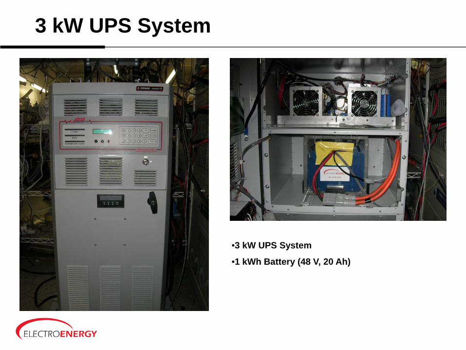
3 kW UPS System
•3 kW UPS System
•1 kWh Battery (48 V, 20 Ah)

3 kW UPS System – Battery Data3 kW Inverter System Battery Performance
Charge and 5 Minute 1500 W Loads
0
10
20
30
40
50
60
70
800 1000 1200 1400 1600 1800 2000
Time (min)
Volta
ge (V
), Te
mpe
ratu
re (d
eg.C
)
Voltage(V) Temperature (C)_1
5 Minute 1500 W Load on Inverter
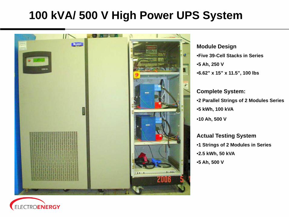
100 kVA/ 500 V High Power UPS System
Module Design•Five 39-Cell Stacks in Series
•5 Ah, 250 V
•6.62” x 15” x 11.5”, 100 lbs
Complete System: •2 Parallel Strings of 2 Modules Series
•5 kWh, 100 kVA
•10 Ah, 500 V
Actual Testing System•1 Strings of 2 Modules in Series
•2.5 kWh, 50 kVA
•5 Ah, 500 V

100 kVA UPS Battery 1-Day Test Profile (50% Load) Cycles 793-804
Battery System has Maintained Consistent Performance Through 800 Cycles
100kVA UPS Battery System 1-Day Test Profile 12 Cycles (793 - 804)
0.00
100.00
200.00
300.00
400.00
500.00
600.00
0 2000 4000 6000 8000 10000 12000 14000 16000 18000
Data Point #
Volta
ge (V
)
-80.00
-60.00
-40.00
-20.00
0.00
20.00
40.00
60.00
Cur
rent
(A)
String 1 Volts Mod 1 Volts Mod 2 Volts DC String Amps

100 kVA UPS Battery Daily Energy In and Out (50% Load), at 800 Cycles
100kVA UPS Total Energy In/Out for Each Day (50% Load)
0
500
1000
1500
2000
2500
1 3 5 7 9 11 13 15 17 19 21 23 25 27 29 31 33 35 37 39 41 43 45 47 49 51 53 55 57 59 61 63 65 67
Day Number
Ener
gy In
or O
ut (W
h)
Total WH Out Total WH Ret
Energy Out of Batteries
Energy In To Batteries
Battery System has Maintained Consistent Performance Through 800 Cycles

Plug-In Hybrid Electric Prius With Electro Energy’s Bipolar Nickel Metal Hydride Battery
Module Configuration Battery System
60 cells, 15 Ah, 73 V, 1.1 kWh Two parallel strings of three modules in series
60 lbs 21.25” x 39.00” x 8.00”, <400 lbs
All electric range: 20-22 miles
23

Plug-In HEV - 19.7 Mile Drive (All-Electric)PHEV Battery Discharge Profile - Parallel with HEV Battery
21.3Ah, 4.5kWh removed – 0.92Miles/Ah, 4.38Miles/kWh)
24
PHEV Prius Test Run07-11-06
100
120
140
160
180
200
220
240
0 400 800 1200 1600 2000 2400 2800 3200 3600 4000 4400
Elapsed Time (Secs)
Bat
tery
Vol
tage
(V)
-60
-40
-20
0
20
40
60
80
100
Bat
tery
Cur
rent
(A)
Battery VoltageB tt C t

Summary and Conclusions
Bipolar cell design was optimizedModule and battery performance was improved
through cell/stack balancingBipolar cell production processes were
developed for volume manufacturingHigh-voltage modules/systems were tested,
achieving multiple cyclesThe bipolar NiMH batteries were demonstrated
in multiple applications

Continued and Future Efforts
Manufacturing Process Development
Bipolar Battery Module Optimization –144 V, 6 Ah High Power Modules–75 V, 20 Ah Energy Modules–110 V, 15 Ah Energy Modules
Battery Systems Pilot and Demonstration

Company Developments April 2006, acquired assets of battery facility in Gainesville,
Florida area formerly owned by Energizer — Leased 200,000 Ft2 of manufacturing space– Simultaneous with acquisition raised working capital to be
used for: Equipment up-grades New Equipment
Gainesville acquisition will accelerate commercialization and growth plans:
High volume electrode manufacturing for Li-Ion and Ni based products
Highly automated capabilities for 18650 Li-Ion cells –30m/yr
Equipment can be adapted for bipolar battery manufacturing
High volume commercialization of bipolar Ni-MH batteries Leverage bipolar expertise developed for Ni-MH into
Lithium-Ion batteries Gainesville facility provides EEI with necessary manufacturing
assets to become a leading supplier of specialty rechargeable batteries in North America
4

Acknowledgements
Electro Energy, Inc. has received funding for this effort from the
Department of Energy.
In particular EEI would like to thank Dr. Imre Gyuk
of The Department of Energy
Nancy Clark and David Ingersoll of
Sandia National Laboratories for Program Management