construction training facility (essu philippines)
TRANSCRIPT
Construction Training Facility
(ESSU Philippines)
A Senior Project Presented to
James Mwangi from the Department of Architectural Engineering
By Omar Ramirez
May 2016
© 2016 Omar Ramirez

TABLE OF CONTENTS
Abstract………………………………………………………………………… Page 3
Background…………………………………………………………………..… Pages 4-6
Background Figures…………………………………………………..………… Pages 6-7
Background Quantity Takeoff and Structural Plans…….…………………….. Pages 8-45
Training Station Layout …..…..…….………………………………………… Pages 46-49
Training Station Layout Figures …..…………...….………………………….. Pages 50-54
The Outcome ………………….…....……………............................................. Pages 55-57
The Outcome Figures………………….…....…………………………………. Pages 55-62
Acknowledgements …………………………………………………………… Page 63

ABSTRACT:
The purpose of this project was to work hand in hand with the engineers and construction
managers from the non-profit organization Build Change in order to build a training facility in
The Philippines. Thus, this project is consistent of three major components and a general image
album for every section. The three major components are as follows:
The first section (Background) of this report exposes the finding and inspiration of this
project. This section also includes estimating the cost of the project and reviewing the structural
details to ensure that all of the necessary components are included. Along with this there is also a
brief summary of the challenges faced when coordinating a project that is being constructed over
7,000 miles away.
The secondary focus of this report (Training Station Layout) describes in essence the role
that every layout of the training facility and gives a detailed description of the importance that
every step in this training has.
The third section of this report (The Outcome) describes what the experience of working
with Build Change was like. There are also more descriptions about preparing for construction
and how my participation in the project concluded. Lastly it describes the benefits of
overcoming the challenges and the personal growth that I have seen in myself as a professional.
Page 3 of 63

BACKGROUND:
Throughout the past five years in the Architectural Engineering program at California
Polytechnic State University I have experienced a multitude of great life changing experiences.
These experiences include challenges anywhere from learning how to cook to learning how to
manage the time to work full time while also attending school full time. From all my life
changing experiences in this program there are two that are the most memorable. One is the
Structural Engineering Students for Humanity (SESH) trip to Haiti in the summer of 2014, and
the other is my senior project. For my senior project I had the opportunity to work with the Build
Change non profit organization in the Philippines. Even though both projects were in very
different locations, they both resemble one another very much. Both projects served one purpose
and this purpose was to help those who are in greater need than us.
After being a part of SESH I decided that I wanted to focus my senior project on
something that would be more geared towards helping the less fortunate. Figure 1 is an image of
my trip to Haiti. The simplicity of an image discloses that the need of the people from third
world countries is greater one can imagine. With this in mind, I knew the right person to
approach for something like this. Professor James Mwangi has been the one professor in the
Architectural Engineering department who has seen it all. He was there right after the Haiti
Earthquake helping assess buildings and he was also there supporting the people in Nepal after
their recent earthquake.
After discussing with him what my goal was with my senior project he contacted me with
the right people. My direct contact for my senior project would be Michael Collins. Michael is
the Director of Education for The Build Change Group and the person behind the construction
Page 4 of 63

and design of all of the training centers that are built by Build Change. The first live chat that I
had with Michael was when he was in Bogota, Colombia. During this FaceTime chat with
Michael, He gave me a general overview of Build Change and then expanded by asking me
several questions about myself.
As mentioned by Michael, Build Change is an organization dedicated to serve the
communities in third world countries by educating the locals with better building techniques. The
Build Change group focuses their efforts to establish a consistent building pattern that is broken
down into different phases which include: determining suitable construction material,
establishing a stable building foundation, reinforcing appropriately in accordance to the use of
the facility, assuring quality control throughout the extent of the construction, and lastly tracking
costs during construction amongst other essentials tied in with construction management.
Michael then proceeded by asking me what my interests were and what he could do to
make a project more interesting for me. I then expressed to him my interest in construction
management along with my interest in making an impact on the lives of people. He immediately
knew exactly what project to place me on. Michael expressed how there was an Eastern Samar
State University (ESSU) project that was expected to start in Guiuan which is located in The
Philippines. The ESSU project consists of building a facility to better train local construction
workers to perform greater quality construction. This construction includes the basic tips to
improve building performance during catastrophic events such as hurricanes and earthquakes.
The goal of Build Change in the Philippines is to push the locals to construct a safe room in case
a catastrophic event occurs. Build Change understands the cost behind constructing a strong
stable home and they know that the locals will not be able to afford such a drastic modification
but they will definitely be able to afford something smaller and still efficient such as a safe room.
Page 5 of 63

When I became a part of this project, there was already a general structural design made
for this safe room. Therefore my first task would be to do a takeoff for the design in order to get
quantities for the construction material. This task was conducted by using a general template that
was sent to me by Michael and which can be at the end of this section. Michael was very specific
about using their template because this would allow anyone on the design team to make any
necessary changes at any time. During the time that I was doing my takeoff I ran into several
conflicts. I encountered issues with the spread sheet, I had to do research on the currency used in
The Philippines, I had to keep in touch with Michael while he was on a different zone, and lastly
I had to begin using metric units for all of my quantity calculations and this is something that I
was not familiar with.
In the documents attached after this section there are copies of the structural plans and
details that were designed and drafted by Build Change engineers as a reference for this project.
The majority of these plans were provided to me after my initial talk with Michael and it was
stated to reference these plans to complete a quantity takeoff for what would be an individual
unit (safe room). I will state that I replicated some of the structures in these plans with Revit in
order to obtain a greater understanding of the building but all of the structural design credit goes
to Build Change. The preliminary models that I created can be seen in Figures 2,3, and 4 and
they were created in a n effort to find any design flaws and to assure that the rebar in the safe
room would fit accordingly.
Page 6 of 63

Figure 1Structura(From left to
Figure 2by Build to providthe rebarcongeste
: This is an ial Engeeringo right: James M
2: This modeChange and
de further detr in this modd for when r
image taken Students fo
Mwangi, Omar R
el was made d a an Autodtail of the buel to ensure real construc
n in Haiti durr Humanity
Ramirez, Hatian C
by using thedesk softwareuilding itselfthat the spac
ction began.
ring the 2014(SESH) tripChildren)
e set of planse product calf. I made surcing would n
4 p.
s provided alled Revit 20re to incorponot be too
015 orate
Page 7 of 63

Last updated: 2014-12-11
Homeowner: Design Date:Address: Printing Date:
Telephone: Engineer/Architect:
Design Code B 1 - CV - CU 1.02 - CU 1.02 - CU 1.02 - CU 1.02 - E OK
Plan Type: B Warnings: 3.5m Front and BackNo. of Stories: 1 Check front wall pier: 1 OK SW-Veranda Type: CV 2 OK CU-
Front Elevation Type: CU Check rear wall pier: 3 OK EU-Front Wall Pier Length: 1.02 m 4 OK EF-
Front Qty Wall Piers: 2 Check left wall pier: 5 OK 4m Front and BackRear Elevation Type: CU 6 OK SW-
Rear Wall Pier Length: 1.02 m 7 OK CU-Rear Qty Wall Piers: 2 Check right wall pier: 8 OK EU-Left Elevation Type: CU 9 OK EF- 2.90
Left Wall Pier Length: 1.02 m 10 OK 3.1m Side Elevation (TV)Left Qty Wall Piers: 2 CU-
Right Elevation Type: CU EU-Right Wall Pier Length: 1.02 m EF-
Right Qty Wall Piers: 2 2.9m Side Elevation (CV)Extension Option: E CU-Verandah Bench: No EU-
Shading: No EF-Parapet: No
Building Info Price of the HouseFootprint Area: m2 ₱167,262
₱10,199 /m2
2.281.85 2.06 2.27
1.02 1.231.65 1.86 2.07
1.85 2.06 2.27 2.481.65 1.86 2.07 2.28 2.49
2.482.48
Wall Pier Lengths for Block Units(m)
1.02 1.23 1.44
1.64 1.85 2.06 2.272.27
1.02 1.231.64 1.85 2.06
1.64 1.85 2.06 2.48
16.4
DARIO BAGOYOROS1-12 (PUROK1, SULANGAN PROPER, GUIUAN)
front back left right
1.47
Bill of Quantities - Basic Design InputsTECHNICAL ASSISTANCE & TRAINING FOR FAMILY-DRIVEN RECONSTRUCTION IN SULANGAN
2/5/20152015/02/09 3:39 PMClement
1.021.64 1.85 2.06
Page 8 of 63

English Homeowner Evaluation Date:PHP Address Print Date:
GPS: Engineer:Design Code
Last updated: 12/16/2014
Item Unit Price (Php) Unit Qty.Cost(Php)
Qty.Cost(Php)
Qty.Cost(Php)
Qty.Cost(Php) Qty.
Cost(Php)
Cement ₱270 /bag 36.00 ₱9,720 35.00 ₱9,450 36.00 ₱9,720 0.00 ₱0 107.0 ₱28,890Black Sand ₱1,300 /m3 2.50 ₱3,250 3.50 ₱4,550 3.50 ₱4,550 0.00 ₱0 9.5 ₱12,350Gravel 12-20 ₱1,300 /m3 2.50 ₱3,250 2.00 ₱2,600 2.50 ₱3,250 0.00 ₱0 7.0 ₱9,10015cm Block ₱38 /each 63.00 ₱2,394 234.00 ₱8,892 0.00 ₱0 0.00 ₱0 297.0 ₱11,28610cm Block ₱20 /each 0.00 ₱0 0.00 ₱0 8.00 ₱160 0.00 ₱0 8.0 ₱160Rebar 8 ₱98 /Bar 40.00 ₱3,920 0.00 ₱0 20.00 ₱1,960 0.00 ₱0 60.0 ₱5,880Rebar 10 ₱135 /Bar 6.00 ₱810 38.00 ₱5,130 0.00 ₱0 0.00 ₱0 44.0 ₱5,940Rebar 12 ₱170 /Bar 79.00 ₱13,430 0.00 ₱0 60.00 ₱10,200 0.00 ₱0 139.0 ₱23,630Binding Wire ₱75 /kg 8.50 ₱638 2.00 ₱150 6.00 ₱450 0.00 ₱0 16.5 ₱1,2381x2 Coconut Lumber ₱2 /foot 0.00 ₱0 0.00 ₱0 71.00 ₱142 0.00 ₱0 71.0 ₱1422x2 Coconut Lumber ₱4 /foot 0.00 ₱0 0.00 ₱0 18.00 ₱72 0.00 ₱0 18.0 ₱72Door (1.1mx2.8m) ₱1,500 /each 0.00 ₱0 0.00 ₱0 2.00 ₱3,000 0.00 ₱0 2.0 ₱3,000Window (1.2mx1.6m) ₱583 //m 0.00 ₱0 0.00 ₱0 4.00 ₱2,333 0.00 ₱0 4.0 ₱2,333
Cost of Materials ₱37,412 ₱30,772 ₱35,837 ₱0 ₱104,021Plywood sheet (4'x8'x1/4") Formwork ₱370 /sheet 3.00 ₱1,110 8.00 ₱2,960 0.00 ₱0 0.00 ₱0 11.0 ₱4,070Plywood sheet (4'x8'x3/4") Formwork ₱980 /sheet 0.00 ₱0 0.00 ₱0 7.00 ₱6,860 0.00 ₱0 7.0 ₱6,8602x2 Coconut Lumber Formwork ₱4 /foot 245.00 ₱980 918.00 ₱3,672 0.00 ₱0 0.00 ₱0 1163.0 ₱4,6522x4 Coconut Lumber Formwork ₱8 /foot 0.00 ₱0 0.00 ₱0 170.00 ₱1,360 0.00 ₱0 170.0 ₱1,3601.5" Nails Formwork ₱75 /kg 3.00 ₱225 0.00 ₱0 0.00 ₱0 0.00 ₱0 3.0 ₱2252.5" Nails Formwork ₱65 /kg 4.00 ₱260 0.00 ₱0 0.00 ₱0 0.00 ₱0 4.0 ₱260
Cost of Formwork ₱2,575 ₱6,632 ₱8,220 ₱0 ₱17,427Cost of Labor ₱12,733 ₱10,404 ₱10,171 ₱0 ₱33,309Holdback: 25% of the cost of labor -₱3,183.35 -₱2,601 -₱2,543 ₱8,327 ₱0 TRANCHES COST FROM FROM
Amount Provided for Labor ₱9,550 ₱7,803 ₱7,628 ₱8,327 ₱33,309 CORDAID BENEFICIARY
Cost of Transport ₱1,999 ₱1,870 ₱2,203 ₱0 ₱6,072 1st ₱53,725 ₱46,463 ₱7,262
Sub-Total ₱54,719 ₱49,678 ₱56,431 ₱0 ₱160,829 2nd ₱49,064 ₱49,064
04% for unforseen costs ₱2,189 ₱1,987 ₱2,257 ₱0 ₱6,433 3rd ₱56,146 ₱56,146
Supplemental unforseen 0% ₱0 ₱0 ₱0 ₱0 4th ₱8,327 ₱8,327
₱53,725 ₱49,064 ₱56,146 ₱8,327 ₱167,262 TOTAL ₱167,262 ₱160,000 ₱7,262
TOTAL FOR ALL TRANCHESTRANCHE 4
Holdback/ Additional
Totals
2015/02/05 12:00 AM
Clement2015/02/09 3:43 PM
TRANCHE 1 TRANCHE 2
DARIO BAGOYOROS1-12 (PUROK1, SULANGAN PROPER, GUIUAN)0B1-CV-CU1.02-CU1.02-CU1.02-CU1.02-E
TRANCHE 3
Page 9 of 63

T-100 TITLE PAGEG-100 GENERAL NOTESG-101 GENERAL NOTESA-001 SITE PLANA-100 GROUND FLOOR PLANA-200 EXTERIOR ELEVATIONSA-201 EXTERIOR ELEVATIONSS-100 FOUNDATION PLANS-101 ROOF PLANS-300 LONGITUDINAL SECTION
S-500 DETAILSS-501 DETAILSS-502 DETAILSS-503 DETAILSS-504 DETAILSS-505 DETAILSS-506 DETAILSS-507 DETAILSS-509 DETAILSS-510 DETAILSS-511 DETAILSS-512 DETAILSS-513 DETAILSS-514 DETAILSS-515 DETAILS
T-100SCALE: N/A
DRAWN BY:MLB
TITLE PAGE
REV :
TECHNICAL ASSISTANCE AND TRAINING FOR FAMILY DRIVEN RECONSTRUCTION IN SULANGAN
STRUCTURAL AND ARCHITECTURAL DRAWINGS FOR THE
DARIO BAGOYORO FAMILY RESIDENCE(S1-12)
PUROK 1, SULANGAN, GUIUANHOME OWNER INFORMATION
NAME: DARIO BAGOYOROPHONE NUMBER:
LOCATION GENERAL BUILDING INFORMATION
AREAGROUNDFLOOR ( M2 )
UPPERLEVEL ( M2 )
HABITABLE AREA 17.3m2 0.0
VENTILATION AREA REQUIRED
VENTILATION AREA PROVIDED
0.0
0.0
1.25m2
6.768m2
DRAWINGS LISTINTERIOR AREA 12.5m2 0.0
DATE : 05/02/2015RESIDENCE OF DARIO BAGOYORO FAMILY
PUROK 1, SULANGAN, GUIUANHOUSE NO. S1-12 Page 10 of 63

A-001REV :
SCALE: N/A
SITE PLAN
DRAWN BY:MT
DESIGN CODE : B1 - CV - CU 1.02 - CU 1.02 - CU 1.02 - CU 1.02 - E
DATE : 05/02/2015RESIDENCE OF DARIO BAGOYORO FAMILY
PUROK 1, SULANGAN, GUIUANHOUSE NO. S1-12
PROPOSED SITE PLANA3
SITE PLANA1
EXISTING SITE PLANA2
Page 11 of 63

GENERAL NOTESI. GENERALA. AN DESINYO HAN BALAY IN NABASE HAN REQUIREMENTS HAN 2010 NATIONAL
STRUCTURAL CODE OF THE PHILIPPINES (NSCP)B. AN MAGHIHIMU HAN BALAY IN RESPONSABLE HAN PAG COORDINATE HAN MGA
TRABAHO NGADA HAN MGA TRABAHANTE NGAN PAG CHECK HAN MGA DIMENSIONS.IGSUMAT HAN ENGINEER NGIN MAYDA PAGKAKAIBA HAN DIMENSION NGAN MAAYUSHIYA BAG O MAG PASIGE AN TRABAHO
C. AN MAGHIHIMU HAN BALAY IN DAPAT MAGHINAY PARA DIRE MAHIBANG ANESTRAKTURA. DAPAT GUMAMIT HIN MGA BRACING NGAN SHORING PARA HAN BUG ATHAN ESTRAKTURA.
D. AN MAGHIHIMU HAN BALAY NGAN AN TAG BALAY IN MAGSUSUMAT HAN ENGINEER ANMGA NATATABO HA SITE NGA DIRE NAAYON HAN DRAWING.
E. AN MAGHIHIMU HAN BALAY IN DAPAT ISIGURADO AN SIGURIDAD HA SITE BASE WARAYMADISGRASYA NGA TAWO.
II. PUNDASYUN
A. AN DESINYO HAN PUNDASYUN IN BASE HAN MGA RESULTA NGA RECOMENDASYONHAN GEOTECHNICAL INVESTIGATION NGAN "RETROFITTING AND RECONSTRUCTIONOF ONE - TWO STOREY HOMES NGOLOS AND SULUNGAN, GUIUA, EASTERN SAMAR"NGA GUINBUHAT HAN A.M. GEOCONSULT AND ASSOCIATES, INC, HAN AUGUST 2014.
B. DESINYO NG PUNDASYON PARAMETERS:1. GINAMIT AN 150KPA NGA ALLOWABLE SOIL BEARING CAPACITY UG AN
PERMITTED 133% NGA PAGHATAAS HAN LOAD UPOD AN TRANSIENT LOADSSUGAD HAN HANGIN O DI KAYA AN LINUG.
2. AN FRICTION COEFFECIENT PARA HAN SLIDING IN 0.45 AN GINAMIT PARAMAPUDNGAN AN LATERAL LOADS .
C. PARA MASUNOD AN NSCP, SITE PREPARATION NGAN FOUNDATION WORK IN DAPATSUMUNOD HAN MGA MASUNOD:
1. DAPAT MALINIS AN PAGTRATRABAHUAN BAG O MAG LEVEL HAN TUNA. 2. WARAY DAPAT BATO NGA MAS MADAKU PA HAN 20CM NGA AADA HAN
PAGTRATRABAHUAN3. AN TAMBAK IN DAPAT NA COMPACT NGA DIRI MAHATAAS AN DAKMUL HIN 20
CM NGAN MAY PINAKAGUTI NGA MAXIMUM DRY DENSITY NGA 95 %4. PAGLAY OUT HAN PUNDASYON NGAN LOKASYON GAMIT AN NYLON NGAN
KAHOYD. FOUNDATION TRENCHES IN DAPAT MABUHAT BASE HAN MGA MASUNOD:
1. MARKAHE AN FOUNDATION TRENCH GAMIT HIN CHALK O NYLON PARA HANMGA DIMENSYUN NGA TIKANG HAN PLANO. DAPAT NAKA 90 DEGREE AN LINYA
2. AN MGA GUIN UKAD PARA PUNDASYON IN DAPAT MALINIS NGAN DAPATWARAY MGA BUTANG NGA MADALI MADUNOT
3. AN PINAKAILARUM HAN GUIN UKAD DAPAT NAKA LEVEL, MALINIS NGAN WARAYTINAMBAK NGA TUNA
E. TURUYA NGAN PROTEKTAHE AN MGA UTILITIES NGA AADA HABANG NGANPAGKATAPUS HAN CONSTRUCTION .
F. TANGGALA AN MGA DATI PA NGA FOOTING , UTILITIES ,ETC NGA POSSIBLEMAKAULANG HIT BAG O NGA CONSTRUCTION, PWERA NALA NGIN NAKABUTANG HAPLANO.
G. PAGSUMAT HAN ENGINEER NGIN MAYDA MAKIT AN NGA MGA ESTRACTURA SUGADHAN CESSPOOLS, CISTERNS, PUNDASYON NGA WARA HA PLANO .
H. AN MAGHIHIMO HAN BALAY IN RESPONSABILIDAD HAN PAG UKAD UPOD NA ANLAGGING, SHORING, UNDERPINNING NGAN PAGPROTEHIT HAN AADA NA NGAGUINBUBUHAT.
I. DAPAT MATANGGAL AN NA EXCAVATE NGA TUNA NGAN NABUBUO NGA DAMU NGATUBIG BAG O MAGBUHOS HAN CONRETO
III. PORMAA. AN PORMA IN DAPAT MAUPAY NGA KLASE ,TADUNG NGAN DI BUKOL BUKOL
B. AN PORMA NGA AADA HIT SALUG IN DAPAT DIRE MAHABUBU HIN 34" NGA PLYWOOD. AN
PANELS IN DAPAT SUPORTADO HIN 2X4 BIGA NGA KAHOY NGA IT HIGRAYO IN USAKAMETRO IT PINAKAHARAYO. DAPAT MASUPORTAHAN AN BIGA(KAHOY) HIN METALNGA POSTE O DI KAYA 2X4 NA POSTE NGA KAHOY O DI KAYA 6CM DIAMETRO NGAPOSTE
(KAHOY) NGA MAYDA PINAKAHATAAS NGA KAHIGRAYO NGA USA KAMETRO.PAGBUTANG HIN SHIMS NGADA HAN ILARUM HAN POSTE PARA HIYA MAGINGESTABLE
C. AN MGA PORMA IN DAPAT MAUPAY AN KAHIMU PARA DIRE TUMURO AN CEMENTPASTE.
D. AN PORMA IN DAPAT MAUPAY AN KABRACE O AN KAHIGUT PARA MAMINTINAR AN IYAPOSISYON NGAN PORMA
E. DAPAT DIRE MAHIBANG AN AADA NA NGA GUINHIMO NGA ESTRACTURA HANPAGHIMU HAN PORMA NGAN SUPORTA.
F. BAG O MAGBUHOS DAPAT AN MGA BUBUHOSAN IN TUBIG TUBIGAN HIN TALA NGANDAPAT TANGGALUN AN PARTE NGA DAMU AN TUBIG. .
G. BAG O MAG BUTANG HIN PORMA PARA CONCRETO NGA POSTE DAPAT TAPUS ANAYAN PAGCONSTRUCT HAN WALLING .
H. CONDUITS, PIPES NGAN SLEEVES NGA NAAGI HIT SALUG, WALLING NGAN BIGA INDIRE NAKAKAAPEKTO HAN KUSOG HAN ESTRACTURAL NGIN DIRE MAS MAMADAKUHIN ONE THIRD HAN DAKMUL HAN SALUG, WALLING NGAN BIGA. .
I. GAMIT HIN BRACE PARA HAN PORMA PARA MAMINTINAR AN TAMA NGA POSISYON.J. KAHUMAN HAN BUHOS AYAW DIRETSO TANGGALA AN PORMA NGAN SUPORTA.
DAPAT DI HIYA MAS MAMAGUTI HAN MGA NAKALISTA:1. VERTICAL TIES NGAN HORIZONTAL RING BEAM NGA DIRETSO NASUPORTA HAN
WALLING: 24 ORAS2. PUNDASYON: DUHA KA ADLAW3. SUSPENDED SLAB NGAN BIGA NGA DIRE DIRETSO NA SUPORTA HAN WALLING: 14
KA ADLAW
K. PAG UPAYA DIRETSO AN MGA AMPAW HIN BALUR HIN TULO KAADLAW PAGKAHUMANMATANGGAL AN MGA PORMA :
1. DIRETSO PAGSUMAT HIT ENGINEER PARA MAPANGINANO BAG O MAGPASIGEAN PAGTUHAY2. NGIN AN AMPAW IN NAKIT AN AN BAKAL DAPAT BASAGUN AN TANAN NGAESTRACTURA NGA NASASAKUPAN HAN MAY AMPAW. BUHUSI NADAMAN PARAWARA NA AMPAW NGA MATABO.3. KUN GUTI LA NGA AMPAW NGAN DI NAKIKIT AN AN BAKAL - TAPALI NALA HINMAS PURO NGA HALO
IV. KABILYAA. AN KABILYA IN DAPAT MAYDA PINAKAGUTI NGA KAKUSUGON HIN 40,000 PSI O 280
MPA (GRADE 40)B. AN MGA KABILYA NGA NAKADA HAN DRAWING IN DAPAT SUMUNOD HAN PINAKAGUTI
NGA KADAKUUN:
C. DAPAT DIRE GUINTATAUY AN BAKAL. AN MGA NABILIN O AN MGA TAPSIK NGACONCRETO NGA NAPIDAR HAN BAKAL IN DAPAT MATANGGAL GAMIT HIN WIRE BRUSHBAG O MAGBUHOS HIN CONCRETO .
D. DAPAT AN MGA HOOKS IN NASUNOD HAN STANDARD PWERA LA NGIN IBA AN GUINAARO HAN DRAWING.
E. DAPAT SUNDUN KUN ANU AN PINAPAKITA HAN PLANO O KUN MAY PUTOL AN KABILYANGAN PUYDE IDIRETSO NALA MAS MAUPAY KUN MAGIGING MAS TIPID HIYA
F. ISIGURADO NGA MAUPAY AN KINAKAPTAN HAN MGA KABILYA BAG O MAGBUHOS
V. CAST-IN-PLACE CONCRETE, MORTAR NGAN CEMENT PLASTERA. AN DESINYO HAN CONCRETO IN NABASE HAN COMPRESSIVE STRENCTH,f'C , NGA
2500 PSI O 17MPA (PINAKAGUTI) PAGKA 28 DAYS.B. CEMENTO: PORTLAND, TYPE 1, MAMARA NGAN DIRE ABRE NGA BAG.C. SAND: BLACK SAND ,MALINIS NGAN NAHUGASAN. BARAS IN PARA PAG PLASTER
NGAN MORTAR, GRABA PARA CONCRETOD. AGGREGATE: CRUSHED, ANGULAR GRAVEL NGA MAS MAGUTI HI 2CM AN KADAKUUN
PARA CONCRETO .E. TUBIG: MALINIS, DIRE MAASIN NGAN WARAY LAGAY
F. AN CONCRETE SPACERS IN DAPAT NAKABUTANG HIT KADA 0.8 METERS NGAN DAPATMAYDA BINDING WIRE NGA NAKAKABIT HA KABILYA BAG O MAGBUHOS HAN CONCRETO
G. DESINYO HAN HALO:
H. PAGPROPOTION, PAGHALO, PAGDARA NGA PAGBUTANG HAN CONCRETO IN NAKABUTANGHAN MGA NASUNOD:1. DAPAT DIDA HIT MALINIS NGA CONCRETO O ASPALTO NGIN MAGHAHALO HIN CONCRETO
DIRE NGADA HIN TUNA2. HALUA ANAY HIN MAUPAY AN BARAS, CEMENTO NGAN BATO BAG O BUTNGAN HIN TUBIG3. PAGDUGANG HIN TUBIG NGIN KAULANGAN PARA MAKUHA AN SAKTO NGA LAPUT HANHALO NGA DIRE MASOBRA HAN NAKADESINYO NGA HALO4. AN LAPUT IN DAPAT MAGRESULTA HIN 5CM NGADTU HAN 10CM SLUMP O PAGTESTINGGAMIT AN KAMUT NGA DIRE MAGAWAS AN TUBIG NGIN GUINKAKAPTAN AN HALO NGAN ANCONCRETO IN DIRE MABUO NGIN BUL IWAN NA
I. KUN MAGLALATAG HIN CHB O BAG O NGA BUHOS NGADA HIT MAY CONCRETO, KAULANGANMASILSILAN ANAY AN CONCRETO PARA DUMUKOT AN BAG O NGA BUHOS.
J. BAG O MAGPALITADA ,HULSA NGAN LINISI O SILSILAN AN PAPALITADAHAN PARA DUMUKOTAN CONCRETO.
K. PAGTUBIGI AN PORMA NGAN BAKAL BAG O MAGBUHOS HIN CONCRETOL. DAPAT BAGO MAG USA KA ORAS KAHUMAN MAGHALO DAPAT AN CONCRETO IN
MAIBUHOS NA. PWERA LA HAN COLUMN NGA MAYDA USA NGA COLD JOINT NGADANINTERMEDIATE BEAM LEVEL IN DAPAT TANAN HIRA MABUHOSAN HIN USA LA KAADALAW
M. GAMIT HIN VIBRATOR O MARTILYO NGAN ROD PARA DIRE MAG AMPAW AN CONCRETO.N. PAGKATAPUS MATANGGAL AN PORMA, HULSA AN CONCRETO LIMA KABESES HIT USA KA
ADLAW NGADA HIT IKA TULO KAADLAW O MAS MADAKU PA PARA MA CURE AN CONCRETOO. BASAGA NGAN BALYUI AN CONCRETO HA TANAN NGA APEKTADO NGA ESTRACTURA NGIN
AN BAG O NGA CONCRETO IN MAYDA HAN MGA NASUNOD : KITA AN BAKAL , MAS DAKO HAN3MM NGA BUTAK HAN CONCRETO, DAMU AN MGA BUTAK O DIAGONAL O PATAAS NGABUTAK HAN BIGA
VI. CONCRETE MASONRYA. AN PAGPALIT HAN MAUPAY NGA KLASE HIN CHB IN RESPONSABILIDAD HAN TAG ADA HAN
BALAY. BAG O PUMALIT HIN CONCRETE HALLOW BLOCKS DAPAT MATESTINGAN ANAY HANTAG ADA HAN BALAY AN KALIDAD HAN CHB TIKANG HAN GUIN PROPOS NGA PARAGHIMUHAN CHB.
B. AN DESINYO HAN CHB IN DAPAT MAYDA MINIMUM COMPRESSION STRENGTH NGA 4MPANGAN MYDA KADAKUUN NGA 15CMX20CMX40CM NGAN DAPAT MAYDA MGA 55% NGAKAHALAPADUN NGADA TULO NGA BUHO HAN CHB
C. TANAN NGA BUHO HAN CHB IN BUTANGAN HIN GROUTD. DAPAT TANAN NGA WALLING IN MAYDA PALITADA . DAPAT IT PALITADA IN MAYDA MGA 1.5
CM NGA KADAKMULUN NGAN DAPAT PALUYO PERO KUN AN DRAWING IN DIRE PALUYODAPAT MASUSUNOD AN DRAWING.
E. DAPAT AN KADAKMULUN HAN GROUT HAN PAGITAN HAN CHB IN DIRE MAGUTI HIN 1CMNGAN DIRE MAMANDAKU HIN 2CM.
F. DAPAT AN PAGLATAG HIT CHB IN KATUNGA HAN IYA HALABA PARA MAS MAKUSOG AN IYAPAGKABUTANG.
G. MORTAR NGAN GROUT: PAGHALUA AN BARAS NGAN CEMENTO NGAN DUGANGI HIN TUBIG.DAPAT MAGAMIT HIYA DIRETSO BAG O MAG 30 MINUTES
H. HULSA HIN MALINIS NGA TUBIG AN CHB BAG O IASINTADAI. AYAW GAGAMIT HIN HIBANG NGAN MAYBUTAK NA NGA CHB. NGIN KAULANGAN HIN DIRE
BUG OS NGA CHB HIT PAG ASINTADA DAPAT KATUNGA HIT BUG OS NGA KAHALABA HANCHB
J. IBUTANG ANAY TANAN NGA CHB PALIBUT BAG O MAGBUTANG HIN MORTAR O GROUT PARALEBELADO AN PAGKABUTANG .
LOKASYONILARUM NGAN LIGID HAN PUNDASYON
LIGID HIT BIGA NGAN POSTE
BUTNGA HAN TIE REINFORCING NGAN MASONRY WALL
ILARUM HAN SUSPENDED SLAB REINFORCING
USE CEMENTCONCRETE 1MORTAR 1GROUT 1PLASTER 1
DESIGNATION DIAMETER LAP LENGHTØ 8MMØ 10MMØ 12MMØ 16MM
8.0MM10.0MM12.0MM16.0MM
30CM40CM50CM65CM
SAND AGGREGATE WATER(MAX)2555
3 1111
SPACER LENGHT (COVER)7.5 CM
4.0 CM
2.5 CM
6.0 CM
G-100SCALE: N/A
DRAWN BY:MLB
GENERAL NOTES
REV :
DATE : 05/02/2015RESIDENCE OF DARIO BAGOYORO FAMILY
PUROK 1, SULANGAN, GUIUANHOUSE NO. S1-12 Page 12 of 63
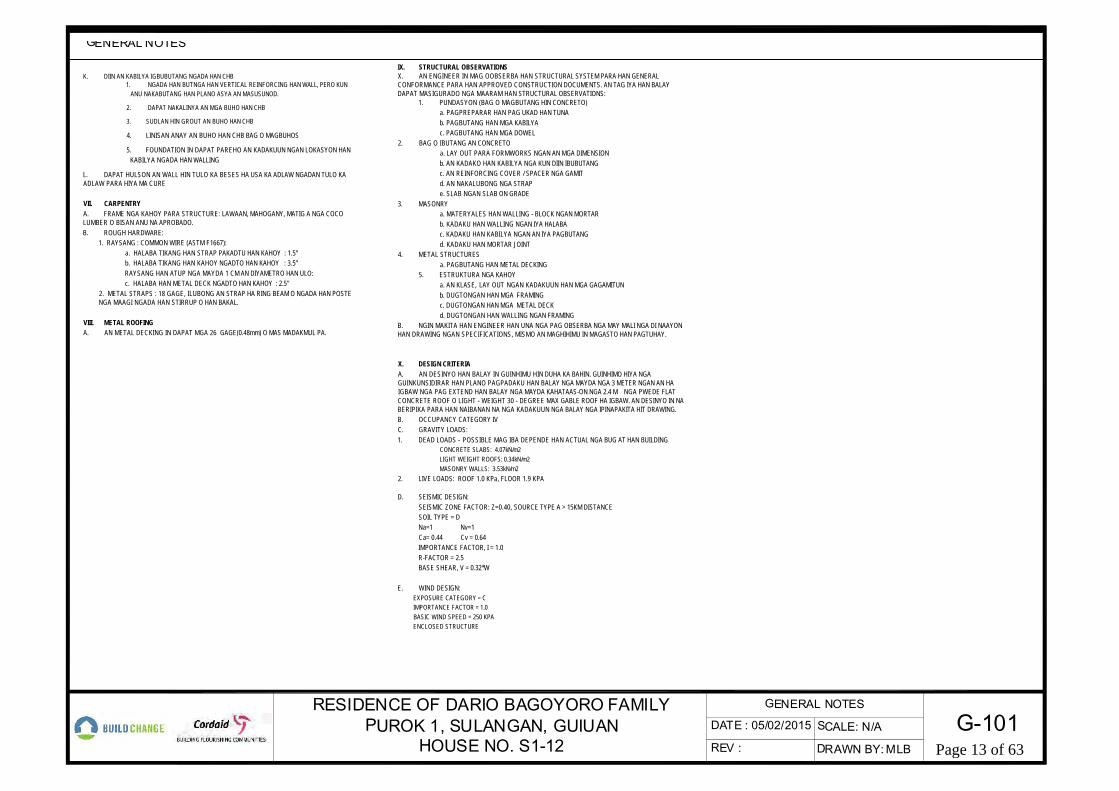
GENERAL NOTES
K. DIIN AN KABILYA IGBUBUTANG NGADA HAN CHB1. NGADA HAN BUTNGA HAN VERTICAL REINFORCING HAN WALL, PERO KUN
ANU NAKABUTANG HAN PLANO ASYA AN MASUSUNOD.
2. DAPAT NAKALINYA AN MGA BUHO HAN CHB
3. SUDLAN HIN GROUT AN BUHO HAN CHB
4. LINISAN ANAY AN BUHO HAN CHB BAG O MAGBUHOS
5. FOUNDATION IN DAPAT PAREHO AN KADAKUUN NGAN LOKASYON HANKABILYA NGADA HAN WALLING
L. DAPAT HULSON AN WALL HIN TULO KA BESES HA USA KA ADLAW NGADAN TULO KAADLAW PARA HIYA MA CURE
VII. CARPENTRYA. FRAME NGA KAHOY PARA STRUCTURE: LAWAAN, MAHOGANY, MATIG A NGA COCOLUMBER O BISAN ANU NA APROBADO.B. ROUGH HARDWARE:
1. RAYSANG : COMMON WIRE (ASTM F1667):a. HALABA TIKANG HAN STRAP PAKADTU HAN KAHOY : 1.5"b. HALABA TIKANG HAN KAHOY NGADTO HAN KAHOY : 3.5”RAYSANG HAN ATUP NGA MAYDA 1 CM AN DIYAMETRO HAN ULO:c. HALABA HAN METAL DECK NGADTO HAN KAHOY : 2.5"
2. METAL STRAPS : 18 GAGE, ILUBONG AN STRAP HA RING BEAM O NGADA HAN POSTENGA MAAGI NGADA HAN STIRRUP O HAN BAKAL.
VIII. METAL ROOFINGA. AN METAL DECKING IN DAPAT MGA 26 GAGE(0.48mm) O MAS MADAKMUL PA.
IX. STRUCTURAL OBSERVATIONSX. AN ENGINEER IN MAG OOBSERBA HAN STRUCTURAL SYSTEM PARA HAN GENERALCONFORMANCE PARA HAN APPROVED CONSTRUCTION DOCUMENTS. AN TAG IYA HAN BALAYDAPAT MASIGURADO NGA MAARAM HAN STRUCTURAL OBSERVATIONS:
1. PUNDASYON (BAG O MAGBUTANG HIN CONCRETO)a. PAGPREPARAR HAN PAG UKAD HAN TUNAb. PAGBUTANG HAN MGA KABILYAc. PAGBUTANG HAN MGA DOWEL
2. BAG O IBUTANG AN CONCRETOa. LAY OUT PARA FORMWORKS NGAN AN MGA DIMENSIONb. AN KADAKO HAN KABILYA NGA KUN DIIN IBUBUTANGc. AN REINFORCING COVER / SPACER NGA GAMITd. AN NAKALUBONG NGA STRAPe. SLAB NGAN SLAB ON GRADE
3. MASONRYa. MATERYALES HAN WALLING - BLOCK NGAN MORTARb. KADAKU HAN WALLING NGAN IYA HALABAc. KADAKU HAN KABILYA NGAN AN IYA PAGBUTANGd. KADAKU HAN MORTAR JOINT
4. METAL STRUCTURESa. PAGBUTANG HAN METAL DECKING
5. ESTRUKTURA NGA KAHOYa. AN KLASE, LAY OUT NGAN KADAKUUN HAN MGA GAGAMITUNb. DUGTONGAN HAN MGA FRAMINGc. DUGTONGAN HAN MGA METAL DECKd. DUGTONGAN HAN WALLING NGAN FRAMING
B. NGIN MAKITA HAN ENGINEER HAN UNA NGA PAG OBSERBA NGA MAY MALI NGA DI NAAYONHAN DRAWING NGAN SPECIFICATIONS, MISMO AN MAGHIHIMU IN MAGASTO HAN PAGTUHAY.
X. DESIGN CRITERIAA. AN DESINYO HAN BALAY IN GUINHIMU HIN DUHA KA BAHIN. GUINHIMO HIYA NGAGUINKUNSIDIRAR HAN PLANO PAGPADAKU HAN BALAY NGA MAYDA NGA 3 METER NGAN AN HAIGBAW NGA PAG EXTEND HAN BALAY NGA MAYDA KAHATAAS-ON NGA 2.4 M NGA PWEDE FLATCONCRETE ROOF O LIGHT - WEIGHT 30 - DEGREE MAX GABLE ROOF HA IGBAW. AN DESINYO IN NABERIPIKA PARA HAN NAIBANAN NA NGA KADAKUUN NGA BALAY NGA IPINAPAKITA HIT DRAWING.B. OCCUPANCY CATEGORY IVC. GRAVITY LOADS:1. DEAD LOADS - POSSIBLE MAG IBA DEPENDE HAN ACTUAL NGA BUG AT HAN BUILDING
CONCRETE SLABS: 4.07kN/m2LIGHT WEIGHT ROOFS: 0.34kN/m2MASONRY WALLS: 3.53kN/m2
2. LIVE LOADS: ROOF 1.0 KPa, FLOOR 1.9 KPA
D. SEISMIC DESIGN:SEISMIC ZONE FACTOR: Z=0.40, SOURCE TYPE A > 15KM DISTANCESOIL TYPE = DNa=1 Nv=1Ca= 0.44 Cv = 0.64IMPORTANCE FACTOR, I = 1.0R-FACTOR = 2.5BASE SHEAR, V = 0.32*W
E. WIND DESIGN:EXPOSURE CATEGORY = CIMPORTANCE FACTOR = 1.0BASIC WIND SPEED = 250 KPAENCLOSED STRUCTURE
G-101SCALE: N/A
DRAWN BY:MLBREV :
DATE : 05/02/2015RESIDENCE OF DARIO BAGOYORO FAMILY
PUROK 1, SULANGAN, GUIUANHOUSE NO. S1-12
GENERAL NOTES
Page 13 of 63
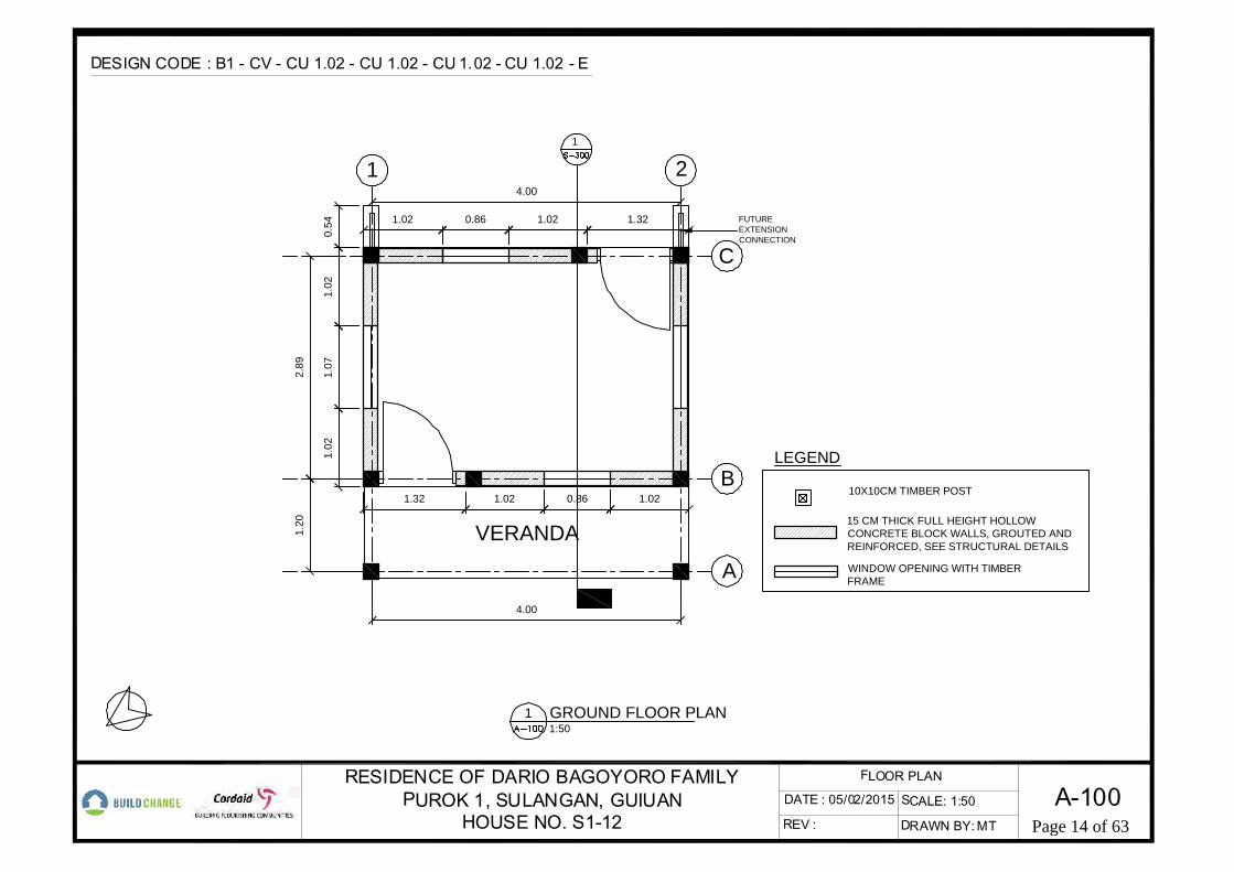
4.00
VERANDA
1
1.02
1.07
1.02
0.54
2.89
1.32 0.86 1.02
1.02 0.86 1.02 1.32
21
C
B
A
1.20
1.02
FUTUREEXTENSIONCONNECTION
10X10CM TIMBER POST
15 CM THICK FULL HEIGHT HOLLOWCONCRETE BLOCK WALLS, GROUTED ANDREINFORCED, SEE STRUCTURAL DETAILS
WINDOW OPENING WITH TIMBERFRAME
LEGEND
4.00
A-100REV :
SCALE: 1:50
FLOOR PLAN
DRAWN BY:MT
GROUND FLOOR PLAN1:50
1
DESIGN CODE : B1 - CV - CU 1.02 - CU 1.02 - CU 1.02 - CU 1.02 - E
DATE : 05/02/2015RESIDENCE OF DARIO BAGOYORO FAMILY
PUROK 1, SULANGAN, GUIUANHOUSE NO. S1-12 Page 14 of 63

0.30
2.84
2.89 1.20
0.54
EXTEND BARS COVEREDWITH LEAN CONCRETEFOR FUTURE 2NDSTOREY EXPANSION
20X20 CM CONCRETECOLUMN
FOUNDATIONBELOW
4.00
3.68
B AC1 2
A-200REV :
SCALE: 1:50
FRONT AND LEFT ELEVATION
DRAWN BY:MT
FRONT ELEVATION1:50
1
DESIGN CODE : B1 - CV - CU 1.02 - CU 1.02 - CU 1.02 - CU 1.02 - E
DATE : 05/02/2015RESIDENCE OF DARIO BAGOYORO FAMILY
PUROK 1, SULANGAN, GUIUANHOUSE NO. S1-12
LEFT ELEVATION1:50
2
Page 15 of 63

2.84
2.891.20
0.54
EXTEND BARSCOVERED WITH LEANCONCRETE FORFUTURE 2ND STOREYEXPANSION
20X20 CM CONCRETECOLUMN
FOUNDATIONBELOW
3.68
EXTENSION FORFUTURE EXPANSION
0.60
4.002 1 A B C
A-201REV :
SCALE: 1:50
FLOOR PLAN
DRAWN BY:MT
DESIGN CODE : B1 - CV - CU 1.02 - CU 1.02 - CU 1.02 - CU 1.02 - E
DATE : 05/02/2015RESIDENCE OF DARIO BAGOYORO FAMILY
PUROK 1, SULANGAN, GUIUANHOUSE NO. S1-12
REAR ELEVATION1:50
1 LEFT ELEVATION1:50
2
Page 16 of 63

80X80X26CMCONCRETE FOOTING,SEE FOUNDATIONDETAIL
50CM WIDE, 26CMTHICK CONCRETESTRIP FOOTING
2 COURSES OF 15CMTHICK CONCRETEBLOCKS
20X20CM CONCRETECOLUMN
2.89
1.20
0.40
1.312.69
4.00
0.40
1.31 2.69
4.00
0.40
0.40
0.250.25
0.60
21
C
B
A
FOUNDATION REBAREXTENSIONPROTECTED BY LEANCONCRETE, FORFUTURE EXPANSION
S-100REV :
SCALE: 1:50
FOUNDATION PLAN
DRAWN BY:MT
FOUNDATION PLAN1:50
1
DESIGN CODE : B1 - CV - CU 1.02 - CU 1.02 - CU 1.02 - CU 1.02 - E
DATE : 05/02/2015RESIDENCE OF DARIO BAGOYORO FAMILY
PUROK 1, SULANGAN, GUIUANHOUSE NO. S1-12 Page 17 of 63
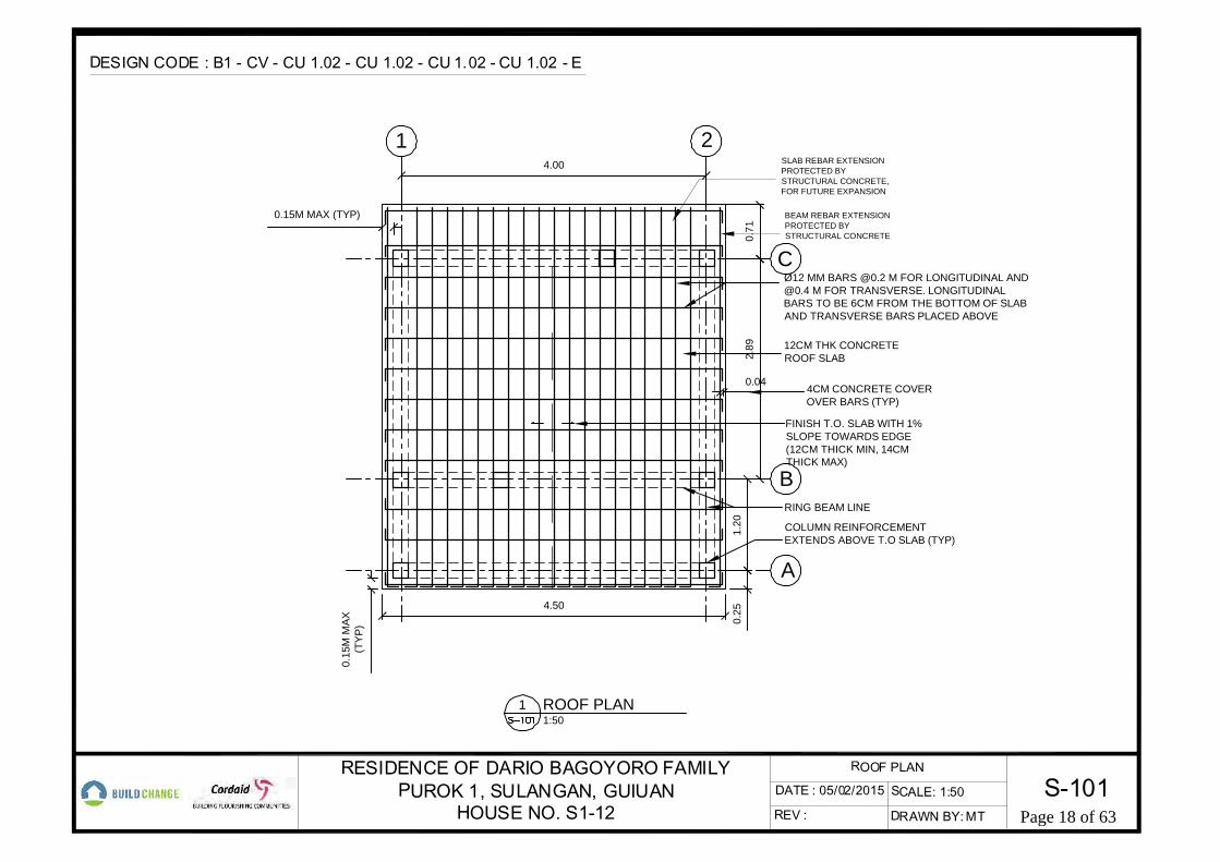
1.20
2.89
0.25
12CM THK CONCRETEROOF SLAB
RING BEAM LINE
FINISH T.O. SLAB WITH 1%SLOPE TOWARDS EDGE(12CM THICK MIN, 14CMTHICK MAX)
Ø12 MM BARS @0.2 M FOR LONGITUDINAL [email protected] M FOR TRANSVERSE. LONGITUDINALBARS TO BE 6CM FROM THE BOTTOM OF SLABAND TRANSVERSE BARS PLACED ABOVE
4.00
0.15M MAX (TYP)
4CM CONCRETE COVEROVER BARS (TYP)
0.04
0.15
M M
AX(T
YP)
4.50
COLUMN REINFORCEMENTEXTENDS ABOVE T.O SLAB (TYP)
C
B
A
21
BEAM REBAR EXTENSIONPROTECTED BYSTRUCTURAL CONCRETE
SLAB REBAR EXTENSIONPROTECTED BYSTRUCTURAL CONCRETE,FOR FUTURE EXPANSION
0.71
S-101REV :
SCALE: 1:50
ROOF PLAN
DRAWN BY:MT
ROOF PLAN1:50
1
DESIGN CODE : B1 - CV - CU 1.02 - CU 1.02 - CU 1.02 - CU 1.02 - E
DATE : 05/02/2015RESIDENCE OF DARIO BAGOYORO FAMILY
PUROK 1, SULANGAN, GUIUANHOUSE NO. S1-12 Page 18 of 63

0.30
2.84
2.89
0.60
20X30CM CONCRETERING BEAM IN FRONTOF VERANDAH
0.54
3.68
COMPACTED SOIL
COMPACTED SOIL
RING BEAM AT BOTHSIDES OF VERANDAHTO BE AT 30CM
CONCRETE STRIP FOOTING WITH (2) CONTINUOUS12MM BARS, SEE PLAN. ALTERNATE DIRECTION OFVERTICAL WALL REINFORCING HOOKS
15 CM HOLLOW CONCRETEBLOCK, FULLY GROUTED WITH10MM VERTICAL BARS @42CMOC MAX, AND HORIZONTALBARS EVERY 3 COURSES OFBLOCKS
EXTEND BARS ANDGROUT WITH LEANCONCRETE FORFUTURE 2ND STOREYEXPANSION
EXTEND SLAB ANDBEAM BARS FORFUTURE EXPANSION
EXTEND WALLREINFORCEMENTBARS FOR FUTUREEXPANSION
EXTEND TIE BEAMBARS FOR FUTUREEXPANSION
EXTENDFOUNDATIONBARS FORFUTUREEXPANSION
0.6MMAX
12CM THICKCONCRETE SLAB
1.20B AC
S-300REV :
SCALE: 1:50
SECTION
DRAWN BY:MT
LONGITUDINAL SECTION1:50
1
DESIGN CODE : B1 - CV - CU 1.02 - CU 1.02 - CU 1.02 - CU 1.02 - E
DATE : 05/02/2015RESIDENCE OF DARIO BAGOYORO FAMILY
PUROK 1, SULANGAN, GUIUANHOUSE NO. S1-12 Page 19 of 63

4.00
1.12 1.02 0.86 1.02
CU - 1.02
1.021.02 1.07
2.89
AT FRONT AND AT REAR
CU - 1.02
AT SIDES
Ø10 MM VERTICAL BARS@42 CM OC MAX (TYP)WITH 15 CM STANDARDHOOK INTO FOOTING ANDBEAM. BARS TO BEINSERTED AT THE 1ST OR3RD CELL OF BLOCKS
MIN
40C
MO
VER
LAP
ATC
ON
NEC
TIO
N
Ø10 MM HORIZONTALREINFORCEMENT IN BEDJOINT EVERY 3 COURSESOF BLOCKS (TYP)THROUGH COLUMN, WITHMIN 40CM OVERLAP ATTHE CONNECTION
(2) Ø10 MM VERTICAL ANDHORIZONTAL BARS ATEDGE OF OPENING
MIN
(4)C
OU
RSE
SO
F BL
OC
KSBE
LOW
WIN
DO
W
NOTE:DO NOT LAP WALL REINFORCING WITHIN MIDDLETHIRD OF WALL LENGHT BETWEEN COLUMNS, ORWITHIN MIDDLE 1.2M OF WALL LENGHT.
MINIMUM BENDING OF BAR WITH NO PARAPET IS 40CM
S-503REV :
SCALE: N/A
DETAILS
DRAWN BY:MT
WALL REINFORCEMENT LAYOUTNOT TO SCALED2.1
DESIGN CODE : B1 - CV - CU 1.02 - CU 1.02 - CU 1.02 - CU 1.02 - E
DATE : 05/02/2015RESIDENCE OF DARIO BAGOYORO FAMILY
PUROK 1, SULANGAN, GUIUANHOUSE NO. S1-12 Page 20 of 63

STRUCTURAL AND ARCHITECTURAL DRAWINGS FOR THE
T-100 TITLE PAGEG-100 GENERAL NOTESA-001 SITE PLANA-100 GROUND FLOOR PLANA-200 EXTERIOR ELEVATIONSA-201 EXTERIOR ELEVATIONSS-100 FOUNDATION PLANS-101 ROOF PLANS-300 LONGITUDINAL SECTION
PUROK 1, SULANGAN, GUIUAN
18.40
12.40
S-500 DETAILSS-501 DETAILSS-502 DETAILSS-503 DETAILSS-504 DETAILSS-505 DETAILSS-506 DETAILSS-507 DETAILSS-509 DETAILSS-510 DETAILSS-511 DETAILSS-512 DETAILSS-513 DETAILSS-514 DETAILSS-515 DETAILS
NAME: FRANCISCO CABERIO PHONE NUMBER: 09265390622
RESIDENCE OF FRANCISCO CABERIO FAMILYPUROK 1, SULANGAN, GUIUAN
HOUSE NO. S1-24
FRANCISCO CABERIO FAMILY RESIDENCE(S1-24)
2.00
7.00
Page 21 of 63

I. GENERALA. THE DESIGN OF THIS HOUSE IS BASED ON THE REQUIREMENTS OF THE 2010
NATIONAL STRUCTURAL CODE OF THE PHILIPPINES (NSCP).B. THE BUILDER IS RESPONSIBLE FOR COORDINATING THE WORK OF ALL WORKERS AND
FOR CHECKING DIMENSIONS. NOTIFY THE ENGINEER OF ANY DISCREPANCIES ANDRESOLVE BEFORE PROCEEDING WITH THE WORK.
C. THE BUILDER SHALL PROVIDE MEASURES NECESSARY TO PROTECT THE STRUCTUREDURING CONSTRUCTION. SUCH MEASURES INCLUDE, BUT MAY NOT BE LIMITED TO,BRACING AND SHORING FOR LOADS DURING CONSTRUCTION.
D. THE BUILDER AND HOMEOWNER SHALL REPORT TO THE ENGINEER ANY CONDITIONSON SITE THAT CONFLICT WITH THE DRAWINGS.
E. THE BUILDER SHALL ASSURE THAT SITE SAFETY IS RESPECTED TO PREVENT INJURYOF PERSONS ON SITE OR ANY DAMAGE.
II. FOUNDATIONSA. THE DESIGN OF THE FOUNDATIONS IS BASED ON THE RESULTS AND
RECOMMENDATIONS OF THE GEOTECHNICAL INVESTIGATION AND REPORT“RETROFITTING AND RECONSTRUCTION OF ONE-TWO STOREY HOMES NGOLOS ANDSULUNGAN, GUIUAN, EASTERN SAMAR” PERFORMED BY A.M. GEOCONSULT ANDASSOCIATES, INC, AND DATED AUGUST 2014.
B. FOUNDATION DESIGN PARAMETERS:1. AN ALLOWABLE SOILD BEARING CAPACITY OF 150KPA WAS USED, WITH A
PERMITTED 133% INCREASE FOR LOAD CASES INCLUDING TRANSIENT LOADS,SUCH AS WIND OR EARTHQUAKE.
2. A FRICTION COEFFEICENT FOR SLIDING OF 0.45 WAS USED TO RESISTLATERAL LOADS.
C. IN ACCORDANCE WITH THE NSCP, SITE PREPARATION AND FOUNDATION WORK SHALLCONFORM TO THE FOLLOWING:
1. CLEAR THE SITE OF ORGANIC MATERIAL PRIOR TO LEVELING THE SOIL. 2. NO ROCK OR SIMILAR IRREDUCIBLE MATERIAL WITH A MAXIMUM DIMENSION
GREATER THAN 20CM SHALL BE PLACED IN FILLS.3. ALL FILLS SHALL BE COMPACTED IN LIFTS NOT EXCEEDING 20CM IN
THICKNESS TO A MINIMUM OF 95 PERCENT OF MAXIMUM DRY DENSITY.4. LAYOUT THE FOUNDATION GEOMETRY AND LOCATION USING NYLON STRING
AND STAKES.D. FOUNDATION TRENCHES SHALL BE CONSTRUCTED WITH THE FOLLOWING
REQUIREMENTS:1. MARK THE FOUNDATION TRENCH LOCATIONS WITH CHALK OR STRING LINE
ACCORDING TO THE DIMENSIONS SHOWN ON PLAN. LINES SHALL BE AT RIGHTANGLES.
2. TRENCHES SHALL BE FREE FROM ORGANIC MATTER.3. THE BOTTOM OF THE TRENCH MUST BE LEVEL, CLEAN AND FREE OF LOOSE
SOIL.E. LOCATE AND PROTECT EXISTING UTILITIES TO REMAIN DURING AND/OR AFTER
CONSTRUCTION.F. REMOVE ABANDONED FOOTINGS, UTILITIES, ETC. WHICH INTERFERE WITH NEW
CONSTRUCTION, UNLESS OTHERWISE INDICATED.G. NOTIFY THE ENGINEER IF ANY BURIED STRUCTURES NOT INDICATED, SUCH AS
CESSPOOLS, CISTERNS, FOUNDATIONS, ETC., ARE FOUND.H. THE CONTRACTOR IS SOLELY RESPONSIBLE FOR EXCAVATION PROCEDURES
INCLUDING LAGGING, SHORING, UNDERPINNING AND PROTECTION OF EXISTINGCONSTRUCTION.
I. REMOVE LOOSE SOIL AND STANDING WATER FROM FOUNDATION EXCAVATIONSPRIOR TO PLACING CONCRETE.
III. FORMWORKA. FORMWORK SHALL BE OF GOOD QUALITY, STRAIGHT AND UNWARPED.B. FORMWORK BELOW SLABS SHALL CONSIST OF ¾” PLYWOOD MINIMUM. THE PANELS
SHALL BE SUPPORTED BELOW BY 2X4 WOOD BEAMS SPACED AT 1 METER MAXIMUM.SUPPORT EACH WOOD BEAM WITH METAL POSTS, 2X4 WOOD POSTS OR 6CM MINIMUMDIAMETER WOOD LOGS AT 1 METER MAXIMUM SPACING. PROVIDE SHIMS AT THEPOST BASES AS REQUIRED FOR STABILITY.
C. FORMS SHALL BE SUBSTANTIAL AND SUFFICIENTLY TIGHT TO PREVENT LEAKAGE OFCEMENT PASTE.
D. FORMS SHALL BE PROPERLY BRACED OR TIED TOGETHER TO MAINTAIN POSITIONAND SHAPE.
E. FORMS AND SUPPORT SHALL NOT DAMAGE PREVIOUSLY BUILT STRUCTURE.F. IMMEDIATELY BEFORE NEW CONCRETE IS PLACED, ALL CONSTRUCTION JOINTS
SHALL BE WETTED AND STANDING WATER REMOVED.
G. INSTALL FORMWORK AT THE VERTICAL TIES AFTER THE WALL CONSTRUCTION ISCOMPLETE AND USE A LEVEL TO CHECK THAT THE FORMWORK IS INSTALLEDPLUMB.
H. CONDUITS, PIPES AND SLEEVES PASSING THROUGH A SLAB, WALL OR BEAM SHALLNOT IMPAIR SIGNIFICANTLY THE STRENGTH OF THE CONSTRUCTION. THEY SHALLNOT BE LARGER IN OUTSIDE DIMENSION THAN ONE THIRD THE OVERALL THICKNESSOF SLAB, WALL OR BEAM IN WHICH THEY ARE EMBEDDED.
I. USE BRACES AS REQUIRED TO MAINTAIN ALL FORMWORK FIRMLY IN THE CORRECTPOSITION.
J. DO NOT REMOVE FORM WORK and supports SOONER THAN THE TIMES INDICATEDBELOW AFTER CASTING THE CONCRETE:
1. VERTICAL TIES AND HORIZONTAL RING BEAMS DIRECTLY SUPPORTED ON WALLS:24 HOURS
2. FOUNDATIONS: TWO DAYS3. SUSPENDED SLABS AND BEAMS NOT DIRECTLY SUPPORTED ON WALLS: FOURTEEN
DAYSK. REPAIR ALL VOIDS IN CONCRETE WITHIN (3) DAYS AFTER FORMS ARE REMOVED AS
FOLLOWS:1. IMMEDIATELY NOTIFY THE ENGINEER FOR REVIEW AND APPROVAL PRIOR TOPROCEEDING WITH A REPAIR.2. VOIDS THAT LEAVE REINFORCING STEEL EXPOSED - CHIP OUT ENTIRESTRUCTURAL ELEMENT. RE-POUR CONCRETE SO THAT NO VOIDS ARE FORMED.3. SMALL VOIDS WITH NO REINFORCING STEEL EXPOSED - FILL VOIDS WITH
CEMENT RICH MORTAR.
IV. REINFORCING STEELA. REINFORCEMENT SHALL BE DEFORMED REINFORCEMENT.B. REINFORCING TO HAVE A MINIMUM STRENGTH OF 40,000 PSI OR 280 MPA (GRADE
40).C. BARS INDICATED IN THE DRAWINGS SHALL CONFORM TO THE FOLLOWING MINIMUM
DIMENSIONS:
D. STEEL SHALL BE RUST FREE. CONCRETE FROM PREVIOUS POURS SHALL BEREMOVED WITH A WIRE BRUSH PRIOR TO POURING CONCRETE.
E. TERMINATE REINFORCING STEEL IN STANDARD HOOKS, UNLESS OTHERWISESHOWN.
F. PROVIDE REINFORCING SHOWN OR NOTED CONTINUOUS IN LENGTHS AS LONG ASPRACTICABLE.
G. PROVIDE MEASURES NECESSARY TO STABLIZE REINFORCING ASSEMBLIES PRIORTO PLACING CONCRETE.
V. CAST-IN-PLACE CONCRETE, MORTAR AND CEMENT PLASTERA. THE DESIGN IS BASED ON CONCRETE COMPRESSIVE STRENGTH, f'C, AT 28 DAYS TO
BE 2500 PSI OR 17.0 MPa, MINIMUM.B. CEMENT: PORTLAND CEMENT, TYPE 1, DRY AND UNOPENED BAGS.C. SAND: BLACK SAND, CLEAN AND WASHED. FINE FOR CEMENT PLASTER AND
MORTAR, COARSE FOR CONCRETE.D. AGGREGATE: CRUSHED, ANGULAR GRAVEL LESS THAN 2CM IN SIZE FOR CONCRETE.E. WATER: CLEAN, NOT SALTY OR MUDDY
F. CONCRETE SPACERS SHALL BE PLACCED AT 0.8M ON CENTER MAXIMUM AND SECUREDWITH BINDING WIRE TO THE REINFORCING BARS PRIOR TO PLACING CONCRETE INACCORDANCE WITH THE FOLLOWING, UNLESS OTHERWISE NOTED IN THE DRAWINGS:
G. MIX DESIGN PROPORTIONS SHALL BE AS FOLLOWS:
H. PROPORTION, MIX, TRANSPORT AND PLACE CAST-IN-PLACE CONCRETE AS NOTED BELOW:
1. MIX ON A CLEAN CONCRETE OR ASPHALT SURAFCE, NOT ON SOIL.2. MIX DRY UNTIL MATERIALS REACH A CONSISTENT COLOR, THEN ADD WATER.3. ADD WATER ONLY AS NEEDED TO REACH DESIRED CONSISTENTCY, NOT EXCEEING THEAMOUNT NOTED IN THE MIX DESIGN PROPORTIONS BELOW.4. CONSISTENCY SHALL RESULT IN SLUMP OF 5CM TO 10CM, OR A HAND TEST THATRESULTS IN NO WATER SPILLING OUT WHEN CONCRETE IS HELD TIGHTLY IN THE HAND, BUTTHE CONCRETE DOES NOT HOLD ITS FORM WHEN RELEASED.
I. AT LOCATIONS WHERE BLOCKS OR NEW CONCRETE WILL BE PLACED ABOVE CONCRETE,SCRAPE THE SURFACE AT ALL INTERFACES AFTER CASTING TO CREATE A ROUGHENEDSURFACE.
J. AT LOCATIONS WHERE CONCRETE IS CAST OR CEMENT PLASTER APPLIED AGAINSTMASONRY, WET SURFACES PRIOR TO PLACEMENT AND CLEAN OF LAITANCE, FOREIGNMATTER, AND LOOSE PARTICLES WITH A WIRE BRUSH OR BY CHIPPING.
K. WET FORMWORK AND STEEL PRIOR TO PLACING CONCRETE.L. PLACE CONCRETE WITHIN 60 MINUTES AFTER MIXING. WITH THE EXCEPTION OF COLUMNS
WHICH CAN HAVE A SINGLE COLD JOINT AT THE INTERMEDIATE BEAM LEVEL, PLACE ANENTIRE ELEMENT (I.E. BEAM) WITHIN ONE DAY.
M. USE A VIBRATOR OR HAMMER AND ROD TO CONSOLIDATE CONCRETE AROUNDREINFORCING.
N. AFTER REMOVING FORMS, CURE THE CONCRETE BY WETTING FIVE TIMES PER DAY FORTHREE DAYS MINIMUM.
O. CHIP OUT CONCRETE FOR THE ENTIRE ELEMENT AND REPOUR ALL CONCRETE ELEMENTSTHAT CONTAIN ANY OF THE FOLLOWING: EXPOSED STEEL REINFORCING, CRACKSLARGER THAN 3MM, NUMEROUS CRACKS IN A LOCALIZED AREA, OR DIAGONAL ORVERTICAL CRACKS IN A BEAM.
VI. CONCRETE MASONRYA. THE PURCHASE OF GOOD QUALITY BLOCKS IS THE HOMEOWNERS RESPONSIBILITY. PRIOR
TO THE PURCHASE OF CONCRETE HOLLOW BLOCKS, THE HOMEOWNER SHALL CONFIRMVIA TESTING, THE QUALITY OF THE BLOCKS MADE BY THE PROPOSED PRODUCER WHOWILL SUPPLY BLOCKS FOR THE HOUSE CONSTRUCTION.
B. THE DESIGNS ARE BASED ON BLOCKS WITH A MINIMUM COMPRESSION STRENGTH OF 4MPa AND OVERALL DIMENSIONS OF 15cm x20cmx40cm AND AT LEAST 55% NET AREA,
WITH THREE CELLS.C. ALL BLOCK CELLS TO BE GROUTED SOLID.D. PROVIDE CEMENT PLASTER FINISH TO ALL MASONRY WALLS. PLASTER TO BE AT LEAST
1.5cm THICK AND APPLIED AT EACH SIDE OF THE WALL, UNLESS OTHERWISE NOTEDE. THE VERTICAL AND HORIZONTAL JOINT THICKNESS SHALL BE BETWEEN 1CM MINIMUM AND2CM MAXIMUM.F. USE A MINIMUM OF 1/2 BLOCK LENGTH BONDING.G. MORTAR AND GROUT: FIRST MIX SAND AND CEMENT AND THEN ADD WATER. USE WITHIN
30 MINUTES OF MIXING OR DISCARD.H. WET BLOCKS WITH CLEAN WATER PRIOR TO PLACING.I. DO NOT USE DAMAGED BLOCKS. IF USING PARTIAL BLOCKS, USE AT LEAST 1
2 OF BLOCK.J. PLACE BLOCKS SO THAT THE UPPER FACE IS LEVEL BEFORE PLACING MORTAR OR GROUT.E.
DESIGNATION DIAMETER8.0MMØ8MM10.0MMØ10MM12.0MMØ12MM16.0MMØ16MM
LOCATION SPACER LENGTH (COVER)
7.5CMBELOW AND AT SIDES OF FOUNDATION REINFORCING
LAP LENGTH30CM40CM50CM65CM
4.0CMSIDES OF BEAMS AND COLUMNS
2.5CMBETWEEN TIE REINFORCING AND MASONRY WALLS
6.0CMBELOW RAISED SLAB REINFORCING
USE CEMENT SAND AGGREGATE WATER (MAX)
CONCRETE 1 2 3 1
MORTAR 1 5
GROUT 1 5
PLASTER 1 5
1
1
1
RESIDENCE OF FRANCISCO CABERIO FAMILYPUROK 1, SULANGAN, GUIUAN
HOUSE NO. S1-24 Page 22 of 63

K. WHERE BARS ARE PLACED WITHIN THE BLOCKS :1. CENTER THE VERTICAL REINFORCING IN THE WALL, UNLESS OTHERWISE
NOTED.
2. VERTICALLY ALIGN THE BLOCK CELLS.
3. FILL ALL CELLS WITH GROUT
4. CLEAN THE CELLS OF MORTAR AND DEBRIS PRIOR TO PLACING THE GROUT.
5. BARS IN THE FOUNDATION SHOULD CORRESPOND WITH THE SIZE ANDLOCATIONS OF THE WALL REINFORCING WITHIN THE BLOCKS.
L. CURE THE WALL BY LIGHTLY WETTING 3 TIMES PER DAY FOR 3 DAYS.
VII. CARPENTRYA. STRUCTURAL WOOD FRAMING: LAWAAN, MAHAGONY, HARD COCO LUMBER ORAPPROVED EQUAL.B. ROUGH HARDWARE:
1. NAILS : COMMON WIRE (ASTM F1667):a. LENGTH AT STRAP-TO-WOOD CONNECTION: 1.5"b. LENGTH AT WOOD-TO-WOOD CONNECTION: 3.5”ROOFING NAILS WITH 1cm DIA. HEADS:c. LENGTH AT METAL DECK-TO-WOOD CONNECTION: 2.5"
2. METAL STRAPS : 18 GAGE, EMBED STRAPS IN RING BEAM OR COLUMN, PASSINGTHE STRAP AROUND THE REINFORCING STIRRUP OR BAR.
VIII. METAL ROOFINGA. THE METAL DECKING SHOULD BE AT LEAST 26 GAGE (0.48mm) OR THICKER.
IX. STRUCTURAL OBSERVATIONSX. THE ENGINEER WILL PROVIDE VISUAL OBSERVATION OF THE STRUCTURAL SYSTEM FORGENERAL CONFORMANCE TO THE APPROVED CONSTRUCTION DOCUMENTS. THE HOMEOWNERSHALL ENSURE ACCESS FOR THE FOLLOWING STRUCTURAL OBSERVATIONS:
1. FOUNDATIONS (PRIOR TO PLACEMENT OF CONCRETE)a. EXCAVATION PREPARATIONb. REINFORCEMENT PLACEMENTc. PLACEMENT OF DOWELS
2. CONCRETE, PRIOR TO PLACEMENTa. FORMWORK LAYOUT AND DIMENSIONSb. REINFORCING STEEL SIZE AND PLACEMENTc. REINFORCING COVER/SPACERS USEDd. EMBEDDED STRAPSe. SLABS AND SLABS ON GRADE
3. MASONRYa. WALL MATERIALS - BLOCK AND MORTARb. WALL SIZES AND LENGTHSc. WALL REINFORCING STEEL SIZE AND PLACEMENTSd. MORTAR JOINT SIZE
4. METAL STRUCTURESa. METAL DECKING INSTALLATION
5. WOOD STRUCTURESa. THE TYPE, LAYOUT AND SIZE OF ELEMENTSb. CONNECTIONS BETWEEN FRAMING ELEMENTSc. CONNECTION TO THE METAL DECKd. CONNECTIONS TO THE WALLS AND FRAMING
B. IF INITIAL OBSERVATIONS MADE BY THE ENGINEER REVEAL THAT ANY PORTION OF THEWORK DOES NOT COMPLY WITH THE DRAWINGS AND SPECIFICATIONS, THE NECESSARY REPAIRSWILL BE MADE AT THE BUILDER'S EXPENSE.
X. DESIGN CRITERIAA. THE DESIGN OF THIS HOME WAS PERFORMED FOR TWO CASES. THE DESIGN WASPERFORMED CONSIDERING A HORIZONTAL EXTENSION TO THE REAR OF THE HOME WHICH IS 3MLONGER THAN THE FLOOR PLAN INCLUDED IN THESE DRAWINGS AS WELL AS A VERTICALEXPANSION OF ONE 2.4M LEVEL WITH EITHER A FLAT CONCRETE SLAB ROOF OR LIGHT-WEIGHT30-DEGREE MAX GABLE ROOF ABOVE. THE DESIGN WAS ALSO VERIFIED FOR THE REDUCED SIZEOF THE BUILDING PRESENTED IN THESE DRAWINGS.B. OCCUPANCY CATEGORY IVC. GRAVITY LOADS:1. DEAD LOADS - VARY BASED ON ACTUAL BUILDING WEIGHTS
CONCRETE SLABS: 4.07kN/m2LIGHT WEIGHT ROOFS: 0.34kN/m2MASONRY WALLS: 3.53kN/m2
2. LIVE LOADS: ROOF 1.0 KPa, FLOOR 1.9 KPA
D. SEISMIC DESIGN:SEISMIC ZONE FACTOR: Z=0.40, SOURCE TYPE A > 15KM DISTANCESOIL TYPE = DNa=1 Nv=1Ca= 0.44 Cv = 0.64IMPORTANCE FACTOR, I = 1.0R-FACTOR = 2.5BASE SHEAR, V = 0.32*W
E. WIND DESIGN:EXPOSURE CATEGORY = CIMPORTANCE FACTOR = 1.0BASIC WIND SPEED = 250 KPAENCLOSED STRUCTURE
RESIDENCE OF FRANCISCO CABERIO FAMILYPUROK 1, SULANGAN, GUIUAN
HOUSE NO. S1-24 Page 23 of 63

A-001REV :
SCALE: 1:100
SITE PLAN
DRAWN BY: MT
DATE : 01/12/2015RESIDENCE OF FRANCISCO CABERIOPUROK 1, SULANGAN, GUIUAN
HOUSE NO. S1-24
N
SITE PLAN PROPOSED SITE PLANEXISTING SITE PLAN
Page 24 of 63

LEGEND
10X10 CM TIMBER POST
1.20
4.30
4.00
B
C
21
A
VERANDAWINDOW OPENING WITH TIMBER FRAME
FUTURE EXTENSIONCONNECTION
1
15 CM THICK FULL HEIGHT HOLLOWCONCRETE BLOCK WALLS, GROUTED ANDREINFORCED, SEE STRUCTURAL DETAILS
TIMBER BENCH WITHDECORATIVE BLOCKS BELOW
PARAPET WITHDECORATIVE BLOCKS
2.00 2.00
3.10
1.47
1.65
1.00 1.641.38
1.00 1.641.38
N
Page 25 of 63

0.30
2.84
3.10 1.20
B AC
0.54 T.O. SLAB
T.O. TIE BEAM
B.O. FOOTING
T.O. COLUMN
EXISTING GRADE
3.68
1.80
4X4" TIMBER POST
TIMBER SCREENFOR SHADING
CGI METAL ROOF
PARAPET WITHDECORATIVEBLOCKS
EXTENSIONFOR FUTUREEXPANSION
1.451.47
4.00
EXTEND BARSCOVERED WITHLEAN CONCRETEFOR FUTURE 2NDSTOREY EXPANSION
FOUNDATIONBELOW
1 2
10X10CMTIMBER POST
CGI METALROOF
TIMBER BENCHWITHDECORATIVEBLOCKS
2.38 1.44
2.00 2.00
Page 26 of 63

TIMBER BENCHWITH DECORATIVEBLOCKS
T.O. SLAB
T.O. TIE BEAM
B.O. FOOTING
T.O. COLUMN
EXISTING GRAD
3.101.20
BA C
EXTENSIONFOR FUTUREEXPANSION
EXTEND BARCOVERED WILEAN CONCRFOR FUTURESTOREY EXP
2.84
0.54
EXTEND BARSCOVERED WITHLEAN CONCRETEFOR FUTURE 2NDSTOREY EXPANSION
20X20 CMCONCRETECOLUMN
FOUNDATIONBELOW
4.001.64 1.38
2 1
1.00
Page 27 of 63

B
C
A
50CM WIDE, 26CM THICKCONCRETE STRIPFOOTING
2 COURSES OF 15CM THICKCONCRETE BLOCKS
20X20CM CONCRETECOLUMN
3.10
1.20
0.40
0.40
0.40
0.40
50X50CM CONCRETEBASE FOOTING, SEEDETAIL D1.3 & D1.4
1
4.002.47
2
1.53
80X80X26CM CONCRETE FOOTINGSEE FOUNDATION DETAIL
FOUNDATION REBAREXTENSION PROTECTEDBY LEAN CONCRETE,FOR FUTURE EXPANSION
0.250.250.25 0.25
0.100.10 1.901.90
2.58 1.64
Page 28 of 63

B
C
A
3.10
12CM THK CONCRETEROOF SLAB
RING BEAM LINE
Ø12 MM BARS @0.2 M FOR LONGITUDINALAND @0.4 M FOR TRANSVERSE.LONGITUDINAL BARS TO BE 6CM FROMTHE BOTTOM OF SLAB AND TRANSVERSEBARS PLACED ABOVE
14.00
2
0.15M MAX (TYP)
BEAM REBAR EXTENSIONPROTECTED BYSTRUCTURAL CONCRETE
SLAB REBAR EXTENSIONPROTECTED BYSTRUCTURALCONCRETE, FOR FUTUREEXPANSION
0.60
4CM CONCRETE COVEROVER BARS (TYP)
0.04
2X4" RAFTER AT EVERY 1 M
2X2" PURLIN AT 0.9M MAX SPACING
TERMINATE SLAB FLUSH WITHFACE OF BEAM. HOOK DOWNSLAB BARS INTO BEAM AT FRONT
4.500.250.25
FINISH T.O. SLAB WITH 1% SLOPETOWARDS EDGE (12CM THICK MIN,14CM THICK MAX)
2X4" FLAT BRACE NAIL WITH (2) 3.5" NAILSTO TOP OF EACH RAFTER AND (3) 3.5" NAILSTO TOP OF POST AND END (TYP)
PERIMETER 2X4" WITH(2) 3.5" NAILS TO EACH PURLIN
COLUMN REINFORCEMENTEXTENDS ABOVE T.O SLAB (TYP)
1.20
0.3M
MAX
Page 29 of 63

0.30
2.84
T.O. TIE BEAM
T.O. SLAB
T.O. COLUMN
B.O. FOOTING
EXISTING GRADE
3.10
BC
0.60
A
0.54
COMPACTEDSOIL
1.80
1.20
CGI METAL ROOFWITH TIMBERSTRUCTURE
COMPACTEDSOIL
CONCRETE STRIP FOOTING WITH (2)CONTINUOUS 12MM BARS, SEE PLAN.ALTERNATE DIRECTION OF VERTICALWALL REINFORCING HOOKS
15 CM HOLLOW CONCRETEBLOCK, FULLY GROUTEDWITH 10MM VERTICAL BARS@42CM OC MAX, ANDHORIZONTAL BARS EVERY 3COURSES OF BLOCKS
EXTEND BARS ANDGROUT WITH LEANCONCRETE FORFUTURE 2NDSTOREY EXPANSION
EXTEND SLABAND BEAM BARSFOR FUTUREEXPANSION
EXTEND WALLREINFORCEMENTBARS FORFUTUREEXPANSION
EXTEND TIE BEAMBARS FORFUTUREEXPANSION
EXTENDFOUNDATIONBARS FORFUTUREEXPANSION
0.6MMAX
12CM THICKCONCRETE SLAB
TIMBER BENCH WITHDECORATIVE BLOCKS
Page 30 of 63

0.80
0.80
0.50
0.50
0.75
0.75
0.75
0.64
0.75 0.64
(4) Ø12 MM COLUMNBARS, WITH 20CM HOOKINTO FOOTING, SEECOLUMN DETAIL FORBARS PLACING
Ø10 MM VERTICAL BARS @42 CMOC (TYP) WITH 15 CM STANDARDHOOK INTO FOOTING,ALTERNATE POSITION
50CM WIDE, 26 CM THICKCONTINUOS CONCRETESTRIP FOOTING
12MM BARS
(2) 12MM BARS
RESIDENCE OF FRANCISCO CABERIO FAMILYPUROK 1, SULANGAN, GUIUAN
HOUSE NO. S1-24 Page 31 of 63

0.80
0.20
2 C
OU
RS
ES O
F BL
OC
KS
0.30
(4) Ø12 MM BARS
0.34
Ø8 MM STIRRUPSFIRST 5 @0.1 M
Ø8 MM [email protected] M (TYP)
80X80X26 CMCONCRETE FOOTING
4 CM THICK CONCRETECOVER (TYP)
20x20 CM TIE BEAM
15 CM THICKNESSBLOCKS
50CM WIDE, 26 CM THICKCONTINUOUS CONCRETESTRIP FOOTING
Ø10 MM VERTICAL BARS@42 CM OC MAX (TYP)WITH 15 CM STANDARDHOOK INTO FOOTING.BARS TO BE INSERTEDAT THE 1ST OR 3RD CELLOF BLOCKS
Ø12 MM BARS EW, WITH10.5CM MIN OF 180° HOOK
0.20
T.O. TIE BEAM
0.757.5CM MIN
CONCRETE COVERB.O. FOOTING
Ø10 MM HORIZONTALREINFORCEMENT IN BED JOINTEVERY 3 COURSES OF BLOCKS (TYP)THROUGH COLUMN, WITH MIN 40CMOVERLAP AT THE CONNECTION
0.26
15CMMAX
0.66
M M
AX
40C
M L
AP
10.5CM
EXISTING GRADE
RESIDENCE OF FRANCISCO CABERIO FAMILYPUROK 1, SULANGAN, GUIUAN
HOUSE NO. S1-24 Page 32 of 63
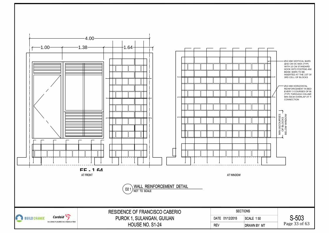
4.00
1.641.381.00
EF - 1.64
Ø10 MM VERTICAL BARS@42 CM OC MAX (TYP)WITH 15 CM STANDARDHOOK INTO FOOTING ANDBEAM. BARS TO BEINSERTED AT THE 1ST OR3RD CELL OF BLOCKS
Ø10 MM HORIZONTALREINFORCEMENT IN BED JOEVERY 3 COURSES OF BLOC(TYP) THROUGH COLUMN, WMIN 40CM OVERLAP AT THECONNECTION
MIN
(4)C
OU
RSE
SO
F BL
OC
KSB
ELO
W W
IND
OW
Page 33 of 63

Ø8 MM STIRRUPSTOP 5 @0.05M
Ø8 MM [email protected]
SEE DETAIL D1.5 FORPOST CONNECTIONTO FOOTING
0.26
(4) Ø10 MM BARS,135° HOOK,12.5CM LONG
50CM MIN
(2) Ø12MM TRANSVERSEBARS, 12CM HOOK LONG
(2) Ø12 MMLONGITUDINAL BARS,12CM HOOK LONG
7.5CMMIN
7.5C
MM
IN
20X20CMCONCRETE PIER
0.12
Ø8 MM STIRRUPS
135° HOOK, ALTERNATEHOOK LOCATION
0.41
0.50
0.50
CONCRETE BASEFOOTING BELOW
0.45
4 CM CONCRETECOVER (TYP)
TIMBERVERANDAHFOOTING, SEEDETAIL D1.3 &D1.4
Ø10MM [email protected] OC EW,WITH 15CM HOOK
0.12
0.12
80X80CM FOUNDATION,SEE DETAIL D1.1 & D1.2
50CM WIDE. 26CM THICKSTRIP FOOTING
15CM THICKCONCRETE BLOCKS
20X20CM TIE BEAM,SEE DETAIL D3.1
COMPACTED SOILBELOW
0.15
0.07
5MM
IN
0.15
2X8" TIMBERBENCH
4X4" POST
PARAPETDECORATIVEBLOCKS
CONCRETE PIERBELOW POSTBEHIND
0.33
STEEL SUPPORTOR TIMBERBLOCK
0.04
VERANDA
SEE DETAIL D1.4 ONWOOD GRAVITY POSTPIER FOUNDATION
4CM WIDE METAL STRAP,EMBEDDED INSIDE THECONCRETE FOUNDATIONHOOK AROUND THIRD TIE
(6) 2.5" LONG NAILS ATEACH SIDE
4X4" OR (2) 2X4" WOODENPOST
0.10
5CM
MIN
2.5C
MM
IN
RESIDENCE OF FRANCISCO CABERIO FAMILYPUROK 1, SULANGAN, GUIUAN
HOUSE NO. S1-24 Page 34 of 63

Ø10 MM HORIZONTAL REINFORCEMENTEVERY 3 COURSES OF BLOCKS (TYP)THROUGH COLUMN, WITH MIN 40CMOVERLAP AT THE CONNECTION
0.15
15 CM THICK BLOCKS,ALL CELLS GROUTED
INSIDE
0.20
0.20
0.055 0.110.
110.035
0.05
50.
035
MINIMUM OVERLAP 40CM (TYP)
135° HOOK, 5 CM LONG,ROTATED (TYP)
Ø8 MM STIRRUPS
(4) Ø12 MM BARS
20X20CM CONCRETE COLUMN
15C
M M
AX
Ø10 MM VERTICAL BARS @0.42M OC MAX (TYP),CENTERED IN WALL
15CM MAX
EQEQ
CEMENT PLASTER, EACH SIDE OF WALL,1.5CM MIN
0.01
50.
015
0.030.
03
0.18
Ø10 MM VERTICAL BARS @42 CM OC MAX (TYP)WITH 12 CM STANDARD HOOK INTO FOOTING.BARS TO BE INSERTED AT THE 1ST OR 3RDCELL OF BLOCKS, CENTERED IN WALL
(2) Ø10 MM BARS, AT EDGE OF OPENING, SEE DETAIL D2.1
15CM THICK CONCRETE BLOCKS,ALL CELLS GROUTED
WINDOW FRAME, REFER TO WINDOW DETAIL
EQEQ
CEMENT PLASTER, EACH SIDE OF WALL,1.5CM MIN
RESIDENCE OF FRANCISCO CABERIO FAMILYPUROK 1, SULANGAN, GUIUAN
HOUSE NO. S1-24 Page 35 of 63
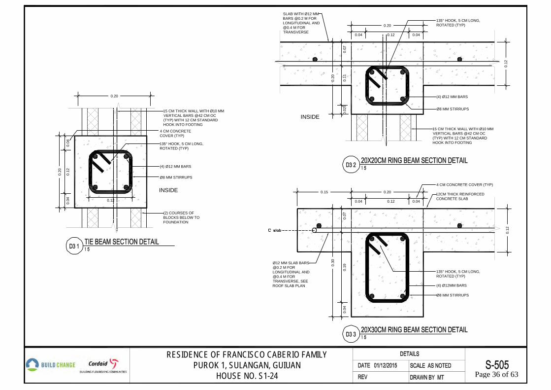
0.20
15 CM THICK WALL WITH Ø10 MMVERTICAL BARS @42 CM OC(TYP) WITH 12 CM STANDARDHOOK INTO FOOTING
(4) Ø12 MM BARS
135° HOOK, 5 CM LONG,ROTATED (TYP)
(2) COURSES OFBLOCKS BELOW TOFOUNDATION
Ø8 MM STIRRUPS
4 CM CONCRETECOVER (TYP)
INSIDE
0.20
0.04
0.12
0.04 0.12
0.20
0.20
0.07
(4) Ø12 MM BARS
Ø8 MM STIRRUPS
135° HOOK, 5 CM LONG,ROTATED (TYP)
0.11
0.12
0.02
5
0.04
15 CM THICK WALL WITH Ø10 MMVERTICAL BARS @42 CM OC(TYP) WITH 12 CM STANDARDHOOK INTO FOOTING
0.04
0.12
SLAB WITH Ø12 MMBARS @0.2 M FORLONGITUDINAL [email protected] M FORTRANSVERSE
INSIDE
0.20
0.30
0.07
0.19
0.12
0.04
0.040.04
135° HOOK, 5 CM LONG,ROTATED (TYP)
Ø8 MM STIRRUPS
4 CM CONCRETE COVER (TYP)
(4) Ø12MM BARS
0.12
0.15
Ø12 MM SLAB [email protected] M FORLONGITUDINAL [email protected] M FORTRANSVERSE, SEEROOF SLAB PLAN
12CM THICK REINFORCEDCONCRETE SLAB
RESIDENCE OF FRANCISCO CABERIO FAMILYPUROK 1, SULANGAN, GUIUAN
HOUSE NO. S1-24 Page 36 of 63

MINIMUM OVERLAP 40 DIA OR 50 CM (TYP)
0.20
COLUMN LINE BELOW
RING BEAM LINE
Ø8 MM STIRRUPSFIRST 5 @0.1 M
Ø12 MM BARS
Ø8 MM [email protected] M (TYP)
INSIDE
0.20
0.04 X 0.04 M CONCRETE SPACER,4 CM THICK CONCRETE COVER (TYP)
0.20
COLUMN LINE BELOW
RING BEAM LINE
Ø8 MM STIRRUPSFIRST 5 @0.1 M
Ø12 MM BARS
Ø8 MM [email protected] M (TYP)
0.20
0.04 X 0.04 M CONCRETE SPACER,4 CM THICK CONCRETE COVER (TYP)
MIN
IMU
M O
VER
LAP
40
DIA
OR
50
CM
(TY
P)0.
055
0.11
0.04
0.12
0.04
Ø12 MM BARS
RESIDENCE OF FRANCISCO CABERIO FAMILYPUROK 1, SULANGAN, GUIUAN
HOUSE NO. S1-24 Page 37 of 63

1.6M MAX
2.50m MAX.
ADDITIONAL (2) Ø12 MM BOTTOMBARS WITH 90-DEGREE HOOK INTOCOLUMN AT EACH END
0.20
0.30
0.20
0.20
20X20CM RING BEAM
20X20CM CONCRETERING BEAM
20X30CM CONCRETERING BEAM
OPENING SOLID WALL
OPENING SOLID WALL
20X20CM CONCRETE COLUMN
COLUMN REBAR EXTENSION
20X20CM CONCRETE COLUMN
COLUMN REBAR EXTENSION
RESIDENCE OF FRANCISCO CABERIO FAMILYPUROK 1, SULANGAN, GUIUAN
HOUSE NO. S1-24 Page 38 of 63

D3.11
SCREEN ELEVATIONAT STRUCTUREPROVISION FORFUTURE EXPANSION
40CM HORIZONTALREINFORCEMENT WALLEXTENSION PROTECTEDFROM WEATHER BY LEANCONCRETE, FOR FUTUREEXPANSION
2X2 TIMBER
1X2 TIMBER OR BAMBOO
50CM SLAB REBAREXTENSION PROTECTEDFROM WEATHER BYSTRUCTURAL CONCRETE,FOR FUTURE EXPANSION
50CM TIE BEAM REBAREXTENSION PROTECTEDFROM WEATHER BY LEANCONCRETE, FOR FUTUREEXPANSION
TIEBEAM
0.08
1% SLOPE
60CM MAX
2.5C
MM
IN4C
MM
IN
Ø10MM HORIZONTALBARS AT EVERY 3COURSES OF BLOCKS
40CM HORIZONTALREINFORCEMENT EXTENSIONPROTECTED FROM WEATHERBY CONCRETE, FOR FUTUREEXPANSION
2X2 TIMBER
1X2 TIMBEROR BAMBOO
20X20CM COLUMN,SEE DETAIL D2.2
MINIMUM OVERLAP 40 DIA OR 50 CM (TYP)
RESIDENCE OF FRANCISCO CABERIO FAMILYPUROK 1, SULANGAN, GUIUAN
HOUSE NO. S1-24 Page 39 of 63

0.75
0.26
(4) Ø12MM DOWELS TO LAPWITH TIE BEAM REINFORCING,COVERED WITH LEANCONCRETE
50CM FOUNDATION REBAREXTENSION PROTECTEDFROM WEATHER BY LEANCONCRETE
10CM THICK BLOCKSUNDER TIE BEAMEXTENSION
TIE BEAM LINE
50CM50CM LAP
COLUMN CENTER LINE
40CM STRUCTURAL CONCRETE 60CM LEAN CONCRETE
0.05
0.10
PROVIDE BLOCK OUT AT TOPOF FOUNDATION AT COLDJOINT BETWEEN STRUCTURALAND LEAN CONCRETE
7.5CM MINCONCRETE COVER
Ø10MM BAR
RESIDENCE OF FRANCISCO CABERIO FAMILYPUROK 1, SULANGAN, GUIUAN
HOUSE NO. S1-24 Page 40 of 63

0.20
1% SLOPE
50CM RING BEAM REBAREXTENSION PROTECTEDFROM WEATHER BYSTRUCTURAL CONCRETE
40CM HORIZONTALREINFORCEMENTEXTENSION PROTECTEDFROM WEATHER BY LEANCONCRETE
0.06
M E
W
50CM COLUMN REBAREXTENSION PROTECTEDFROM WEATHER BYLEAN CONCRETE AND (2)ROWS OF CONCRETEBLOCKS
(5) Ø8MM TIES
40CM VERTICAL BARSEXTENSION, HOOK DOWNAND PROTECT WITH LEANCONCRETE
0.20
0.09
RESIDENCE OF FRANCISCO CABERIO FAMILYPUROK 1, SULANGAN, GUIUAN
HOUSE NO. S1-24 Page 41 of 63

2X2 PURLIN
CGI / METAL ROOF SHEET
1X6 FASCIA BOARD
(2) 2.5" NAILS
2X6" BEAM WITH 58"Ø BOLT
2X4 RAFTER @1M OC MAX
2X4" TOP PLATE
CONTINUOUS 2X4 WOODLEDGER MOUNTED TOCOLUMN, HOOK STRAPFROM RAFTER AROUNDTHE BLOCK
20X20CM REINFORCEDCONCRETE RING BEAM
4X4" POST
18GA X 5CM STRAP WITH (4) 1.5"NAILS TO EACH SIDE OF RAFTER.PROVIDE SIMILAR STRAP TO TOPAND BOTTOM FACES OF 2X4 FLATBRACES.
2X4" FLAT BRACE
(3) 3.5" NAILS TOTOP OF POST
NOTCH RAFTER AND BEAM
TOP PLATE CONNECT WITHMETAL STRAO TO CONCRETECOLUMN, SEE DETAIL D4.2
2X4 BLOCK BELOW PURLIN WITH (4) 3" TOENAILS TO RAFTERS AT EACH END ATCENTER TWO BAYS WHERE PURLINS ARECUT BACK FOR FLAT BRACING. 3.5" NAIL ATEND OF CUT PURLIN TO BLOCK.
(2) 3.5" NAILS FLAT BRACETO EACH RAFTER
RESIDENCE OF FRANCISCO CABERIO FAMILYPUROK 1, SULANGAN, GUIUAN
HOUSE NO. S1-24 Page 42 of 63

2X4"
20X20 CONCRETE COLUMN
0.10
20X20CM CONCRETE COLUMN
18GA 5X15CM METAL STRAP WITH(5) 1.5" NAILS TO FRAMING
2x4" TOP PLATE
4x4" POST
(4) 3.5" NAILS TO COLUMN
PLAN
SECTION
0.025
0.0250.
10
18GA 5X15CM METAL STRAPWITH 1.5" NAILS TO FRAMING
58"Ø BOLT WITH WASHER
EACH SIDE
4X4" POST
2X6" BEAM
EQEQ
2X4" FLAT BRACE
RESIDENCE OF FRANCISCO CABERIO FAMILYPUROK 1, SULANGAN, GUIUAN
HOUSE NO. S1-24 Page 43 of 63

ROOFING NAILS, NAILED AT EVERY WAVE (15CM OC MAX)AT ROOF EDGES, OVERHANGS, AND RIDGES. NAILED TO
THE PURLIN AT EVERY TWO WAVES ELSEWHERE
2X4" RAFTER
PURLIN AT 90 CM SPACING MAXIMUM, SEE D4.4
15CM OVERLAP
CGI / METAL SHEET ROOF AT MINIMUM26GATHICK. PLACE SHEET STRAIGHT
AND IN LINE WITH ONE ANOTHER
18GA X 4 CM METAL STRAP ON BOTHSIDES TO CONNECT WITH RAFTER, USE
(4) 2" NAILS TOTAL AT PURLIN AND(4) TOTAL AT RAFTER
2X4" WOOD RAFTER AT 1M SPACING MAXIMUM
90 CM SPACING MAXIMUM
2X2" WOOD PURLIN ATMAXIMUM 90 CM SPACING
2X4" RAFTER(2) 4" NAILS EACH BLOCKTO 2X2 AND (2) 4" NAILSTO 2X4
2X2" PURLIN
(4) BLOCKS
BB
A
A
(2) 4" NAILS EACHBLOCK TO 2X2
(2) 4" NAILS EACHBLOCK TO 2X4
PLAN
SECTION A-ASECTION B-B
2.5CM
2.5C
M
1.25
CMTY
P
RESIDENCE OF FRANCISCO CABERIO FAMILYPUROK 1, SULANGAN, GUIUAN
HOUSE NO. S1-24 Page 44 of 63

Ø12 MM COLUMN BARS,EXTEND TO 50 CM FORFUTURE UPPER STOREYEXPANSION, COVEREDWITH LEAN CONCRETE
CONCRETE ROOF SLABEDGE LINE, UNLESSOTHERWISE STATED
9CMX9CM LEAN CONCRETECOVER
0.15
0.15
0.09
0.20
0.15
50CM REBAR EXTENSIONPROTECTED FROMWEATHER BY LEANCONCRETE AND (2)ROWS OF CONCRETEBLOCKS
(4) Ø12 MM BARS
Ø8 MM [email protected] M (TYP)
Ø8 MM STIRRUPSFIRST 5 @0.1 M
0.04 X 0.04 M CONCRETESPACER, 4 CM THICKCONCRETE COVER (TYP)
50C
M M
IN A
BO
VE
SLAB
0.20
DRIP MOLD
Ø10 MM HORIZONTALREINFORCEMENT EVERY 3COURSES OF BLOCKS (TYP)THROUGH COLUMN, WITH MIN40CM OVERLAP AT THECONNECTION
Ø10 MM VERTICAL BARS@42 CM OC (TYP) WITH12 CM STANDARD HOOKINTO FOOTING. BARS TOBE INSERTED AT THE1ST OR 3RD CELL OFBLOCKS
Ø12 MM SLAB BARS @0.2 MOC FOR LONGITUDINAL [email protected] M OC FOR TRANSVERSE
40CM VERTICAL BARS EXTENSION,HOOK DOWN AND PROTECT WITHLEAN CONCRETE
0.09
RESIDENCE OF FRANCISCO CABERIO FAMILYPUROK 1, SULANGAN, GUIUAN
HOUSE NO. S1-24 Page 45 of 63

TRAINING STATION LAYOUT:
The concept behind The ESSU Training Center is to have qualified people training
builders to use their local materials in an effort to build structurally stable buildings. The
sequence of training at this center has been set up to assimilate every day construction. By
dividing the learning phases into seven different training stations, Build Change believes that the
locals will be able to have a better understanding of what building seismically sound building
consists of.
The first training station of the facility addresses site lay-out along with assuring the
appropriate material usage before starting. Laying out the site, which is often done through a
surveyor in this country, is essential to getting a project started at the correct location. Figure 5
shows the local Build Change engineer showing the locals how to lay-out a site. Keeping in
mind that most of these less fortunate countries use masonry for the majority of their
construction, Build Change has found ways to provide both builders and suppliers with the
appropriate information to determine whether or not their material is adequate for seismically
stable construction.
In order to select a good material for construction, the builder must know where the
aggregates for the supply are being pulled from. A lot of times the sand used sill contain
corrosive materials which will affect the chemical reaction within the aggregates during the
CMUs cure time. Having CMUs that look good but do not perform as they should, determines
whether a building will stand or collapse during severe weather conditions and other natural
disasters.
The second training station, and probably one of the most critical is the placement of the
rebar reinforcement in the foundation (Figures 6,7,and 8 for more details). As I learned in my
Page 46 of 63

Masonry Design Class at California State University San Luis Obispo with Professor James
Mwangi, CMU is mainly strong in compression. Knowing and understanding a materials
strengths and weaknesses is important. Logically we believe that a heavy material such as a
CMU will be strong in every way due to its appearance but what we do not see is what makes it
strong. In order to make CMUs the amazing material that it is, one must place rebar inside during
construction. Assuring that rebar is securely placed is just as important as assuring that it is
properly tied. Rebar is the strengthening component that allows a greater tolerance when tension
is applied to the members. It is important to know that when a building is standing still the
majority of its components act in compression. However, when movement is incorporated into
the equation, the CMU components begin to fluctuate between compression and tension forces.
This is when a materials real strength is tested. How much force can be applied on a material
before failure, and when failure occurs will this failure be detrimental to the stability of the
remainder of the structure. In simpler terms, will a falling wall make the entire building collapse?
Rebar placement is so crucial that the third station continues to address the handling of
rebar in beams and columns (See Figure 9). As previously mentioned, setting up rebar
appropriately and tying it accordingly can go a long way. The main structural designers in this
case are the engineers from build change. I had no input on the actual structural designs
implemented on this project; however, I did manage to obtain essential knowledge about the
importance of blending two materials such as rebar and CMUs.
Fourthly, the continuing station is dedicated to the masonry layout. Placing CMU in a
proper fashion is a crucial step in construction. In accordance to the engineering knowledge
obtained from the various material classes that I participated in throughout my college career, I
can affirm that in order to appropriately design masonry, one must consider the joint thickness of
Page 47 of 63

the CMU placement during the structural design phase. Setting an appropriate joint thickness and
making sure that this joint thickness is consistent during construction will give assurance that the
building is acting in accordance to its design. In order to comply with this necessity, the walls
must be string lined during erection. By string lining, the mason laying down the CMUs will be
able to maintain a level wall both vertically and horizontally. The term string lining is generally
setting up a string that runs on the upper portion of the CMU blocks that are being placed. This
string line will already have the appropriate joint thickness taken into account and when laying
down the blocks the mason must align the blocks to the string line by taping the corners
accordingly until the block is leveled.
In station five, the locals are trained to properly stage the construction of the building. It
is obvious that a building cannot be started at the roof and work its way down to the foundation,
but there are other steps that are not as obvious. An example is displayed in Figure 10 found in
the image section of this report. In this image you can see the difference between two column
designs. One is a typical square concrete column that is formed and poured straight from the
foundation and then the masonry is placed to fill in the holes. This is in fact the way that Build
Change opted to design these trainings. The other is an example of an interlocking system that
requires the CMU wall placement before the column can be poured. This system, even though
very effective, was not necessary in this project. From both of these examples it is possible to see
how one will require columns to be poured prior to laying down a wall and the other requires a
wall to be placed before a column can be poured. Once all of the walls are poured there comes
the part that most people are skeptical about during an earthquake; the roof.
The sixth training station elaborates on the construction and assembly of the roof. After
experiencing the fear in the people of Haiti of being trapped under the collapse of a heavy roof,
Page 48 of 63

many people have opted to go back to a light weight roof which is of course not as efficient
during a hurricane if the anchorage is not designed accordingly. Studies have shown that with the
proper fasteners and the proper assembly, a light weight roof can perform just as good as a heavy
solid roof. It is conceptually important to know how both roofs are assembled because a well-
designed solid roof/ceiling must be in place if the owner intends to ever use it as a floor for an
additional story. A brief engineering explanation for this would be that a second story floor will
experience larger loads that a typical roof, therefore the structural design for this would possibly
require additional rebar and possibly a thicker slab in order to support the loads.
The last station is more of an observational station. Station seven explicitly demonstrates
a finished product allowing the trainees to view a finished product of what they are training for.
By observing and knowing the importance of every component of a building the trainees will be
able to make appropriate decisions during construction. Without a good understanding of what is
being built it is hard to have a nice deliverable product. With something as simple as the
connection from the foundation to the walls and the connections from the walls/beams to the
roof, it is possible to maximize the structural performance of a building during a seismic event.
In essence a good structural design is one that ensures that all of its connections will yield before
they fail. Yielding is an important factor in structural design because it allows the different
components to give a warning before failure. In essence a yielding connection will allow for two
things such as a roof and a wall to remain connected even though there might be signs of
deformation. Allowing this connection to remain acting as one is important because if this
connection were to fail, then roof and the walls would act as separate components and then the
roof would most likely collapse as it is separated from its only vertical support, the wall.
Page 49 of 63

Figure 5: Build Change Resident Engineer Gilbert Appa wearing a white hard hat and a black shirt is explaining the site specific dimensions to begin construction.
Figure 6: This rebar is for the column foundation which will be poured after the CMU is placed on the sides as seen in some of the following figures.
Page 50 of 63

Figure 7: Local Pilipino mason places foundation CMU blocks and is getting ready to place the horizontal rebar above the CMU. The horizontal rebar can be seen laying besides the CMU. Also a good idea to observe the string line method used to keep the CMU lined up correctly.
Page 51 of 63

Figure 8: This image shows the initial digging of the foundation trenches. Pay close attention to the small work area of the work station as it plays a huge roll in the design of the general site layout.
Page 52 of 63

Figure 9: In this image the locals are observing how rebar should be tied in columns. On the right side of the picture there is column steelwork that is all tied up and ready for concrete. notice that the column steelwork has been leveled out and supported with wood cross braces in preparation for the concrete pour.
Page 53 of 63

Figure 10: This is a demonstration of two types of columns in masonry. To the left is a column poured before the placement of any CMU. To the right is a column poured after the placement of concrete. Note that the interlocking pattern on the left helps to keep the walls united to the column and it also creates a better lateral support for the walls by creating moment connections on the sides.
Page 54 of 63

THE OUTCOME
Building the ESSU Training Facility was not an easy task. One of the largest challenges
to begin the project was cleaning the rumble that was found in the existing site. The existing
rumble can be seen in Figures 11 and 12 at the end of this section. Aside from the entire rumble,
the chosen site was also a very compact site. This means that the majority of the work during the
stripping of the site was manual labor.
While the cleaning of the site was being done, Michael and myself coordinated together
to establish the best fit for the training station layout. In order to do this we had to take into
account the necessary spacing between each station to allow for appropriate movement when
constructing. This site layout planning also entailed incorporating accessibility to transfer
material in and out of the site during construction. The proposed and final layouts can be seen in
Figures 13, 14, and 15. Once our general layout was established, the takeoff that was originally
done had to be manipulated accordingly to account for the building material in each training
station. Once all of the material was accounted for the following step was trying to find the
material through the websites of the local vendors. This is when Google Translator came in
handy.
Throughout the project, maintaining communication with Michael out of Colombia was
challenging enough. Later in the project, maintaining communication with Gilbert Appa, the
resident engineer in The Philippines, became even more challenging. In occasions our calls
would be at 3:00am just so that all three of us could be in the call at once. Managing waking up
at that time while having to manage going to school, doing homework, and working early shifts
on a daily basis really helped me become a better organized person. Another challenge that
expanded my knowledge and made me a more resourceful person was fact that I had to learn the
Page 55 of 63

use of software programs such as Sketchbook, which is the primary aesthetic design program
used by Build Change.
Prior to this project the majority of my experience with drafting had been done through
Revit and AutoCAD. When I initially started this project I modeled the safe room in Revit and
then I made typical details in AutoCAD. After a couple of weeks the majority of my work was
being performed in Sketchup.
Being a part of the College of Architecture and Environmental Design was a great benefit
for me. Luckily while doing my project I was taking an interdisciplinary class with a few
architects and construction managers. These people really helped me out to learn such programs.
The one architect student who helped me out the most through this entire project was Thomas
Husser. Thomas was a foreign exchange student from France who was attending CalPoly for a
year and who had a clear understanding of the project and an extensive knowledge of all of the
programs that I was using.
Right after the clearing of the site and prior to the official start of construction, Thomas
asked me if he could assist with doing anything else for the project. He then volunteered to
model out some of the sketch up model while I assisted Michael and Gilbert with assuring that
the material that would be ordered would meet quality standards for building. Once the visual
model was finished and presented to Michael we all agreed that some necessary changes had to
be made to the overall project. Having a visual understanding of what the site would look like
through the model, we were able to point out some flaws and downsides to the elected order of
the construction phasing. In addition to the changes in phasing, Gilbert noted that it would be
best if we incorporated a station to demonstrate the construction of light weight roofs. The reason
being is because the material cost for building a light weight tin roof is typically cheaper than a
Page 56 of 63

heavy solid roof. These substantial changes obligated us to start redesigning the layout from
scratch.
As imagined, these design changes caused frustration amongst many of us. Thomas was
no longer able to create another model due to availability issues, contacting the material
suppliers to change the original orders became hectic, and the intended time of completion for
the project had to be extended. Even though these changes caused frustration they were also a
great learning experience. It has been proven through this project that even though the changes
caused frustration, the right decisions were made by making these changes. Overall the purpose
of this project was to help the locals to improve their building skills and by expanding their
training through the changes made, the locals were able to obtain more out of the learning
experience.
In conclusion I can state that the experience of being a part of a project focused on saving
lives through proper living was great. The outcome of the project has had and will continue
having a positive impact in my life and in the life of those that go through the training of this
program. Attached in Figure 16 it is possible to see the attentiveness in which the locals grasp all
of the given information. It is because of images like this that this project was worth the time,
effort, and stress to complete.
Page 57 of 63

Figure 11: This image displays the rumble that had to be cleared from the site location for the ESSU Construction Training Facility in Guiuan, the Philippines. Mini Excavator in the back (Northeast Corner)
Figure 12: This image displays the rumble that had to be cleared from the site location for the ESSU Construction Training Facility in Guiuan, the Philippines. (South Side)
Page 58 of 63
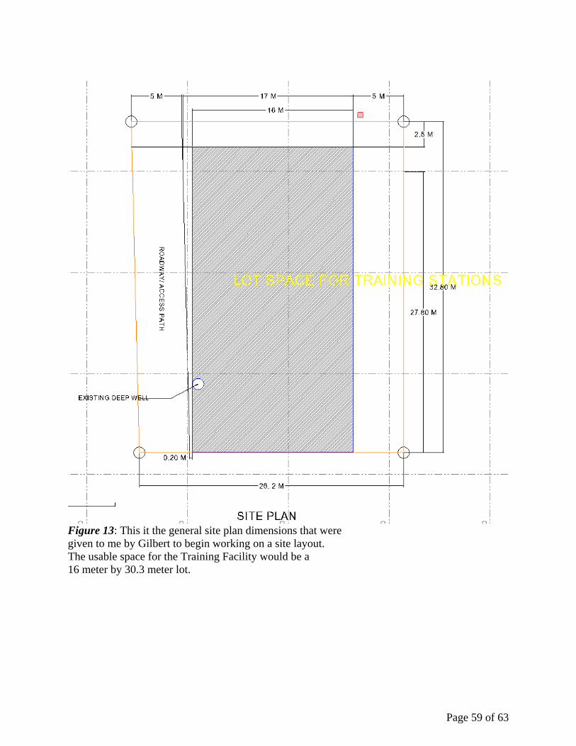
Figure 13: This it the general site plan dimensions that were given to me by Gilbert to begin working on a site layout. The usable space for the Training Facility would be a 16 meter by 30.3 meter lot.
Page 59 of 63

Figure 14: This is the proposed site layout plan for the training stations that I submitted to the Build Change staff for approval.
Page 60 of 63

Figure 15: This was the final site plan position of training stations that was approved by Build Change and that was constructed as part of the ESSU Construction Training Facility.
Page 61 of 63

Figure 16: This image reveals the eagerness in learning as Gilbert Appa, The Build Change Resident Engineer, explains the structural details of the foundation to the locals.
Page 62 of 63

ACKNOWLEDGEMENTS:
I would like to express my deepest appreciation to all of those who provided me the
possibility to complete this project. A special gratitude I give to my Senior Project Advisor
Professor James Mwangi for contacting me with the right people and for being my foundational
support throughout my years at Cal Poly.
In addition I would like to also acknowledge the crucial role of the Staff of Build
Change, who gave me the permission to use all of the required material to make this project
possible. A special thanks goes to the Director of Education of Build Change, Michael Collins,
and the Build Change Resident Engineer in The Philippines, Gilbert Appa. Without these two
people, The HSSU Training Facility would not exist.
One last acknowledgment goes to Thomas Husser, a Cal Poly colleague, for providing
his time and dedication to this project without asking for anything in return. Without the people
listed above, this project could not have been made possible. Thank you all for sharing your
time, knowledge, and passion for this project.
Page 63 of 63