configuring the ncu - siemens ag · and menu item “support”. ... (e.g. using an independent...
TRANSCRIPT

Valid for
ControlSINUMERIK 840DSINUMERIK 840DE (export version)SINUMERIK 840D powerlineSINUMERIK 840DE powerline
DriveSIMODRIVE 611 digital
03/2006 Edition
SINUMERIK 840D
Configuring the NCU
Manual
System Overview 1
Connection Conditions 2
Structure and Installation 3
Description of the NCU 4
I/O Modules 5
Terminal Block 6
DMP Compact Modules 7
Maintenance and Service 8
Abbreviations A
Index

SINUMERIK® documentation
Printing history
Brief details of this edition and previous editions are listed below.
The status of each edition is shown by the code in the “Remarks” column.
Status code in the “Remarks” column:
A New documentation.. . . . . B Unrevised reprint with new Order No.. . . . . C Revised edition with new status. . . . . .
Edition Order No. Remarks06.94 6FC5297-0AC10-0BP0 A08.94 6FC5297-0AC10-0BP1 C02.95 6FC5297-2AC10-0BP0 C04.95 6FC5297-2AC10-0BP1 C09.95 6FC5297-3AA01-0BP0 Description of differences03.96 6FC5297-3AC10-0BP0 C08.97 6FC5297-4AC10-0BP0 C12.97 6FC5297-4AC10-0BP1 C12.98 6FC5297-5AC10-0BP0 C08.99 6FC5297-5AC10-0BP1 C04.00 6FC5297-5AC10-0BP2 C10.00 6FC5297-6AC10-0BP0 C09.01 6FC5297-6AC10-0BP1 C11.02 6FC5297-6AC10-0BP2 C11.03 6FC5297-6AC10-0BP3 C12.04 6FC5297-7AC10-0BP0 C03.06 6FC5297-7AC10-0BP1 C
TrademarksAll product names mentioned may be trademarks or product designations of Siemens AG or their suppliers,whose use by third parties for their own purposes may infringe the rights of the trademark owners.
Further information is available in the Internet under:http://www.siemens.com/motioncontrol
This publication was produced with Interleaf V 7.
Copyright© Siemens AG, 2006.
Other functions not described in this documentation might beexecutable in the control. However, no claim can be made regardingthe availability of these functions when the equipment is first suppliedor in the event of servicing.
We have checked that the contents of this document correspond tothe hardware and software described. Nevertheless, differencesmight exist and therefore we cannot guarantee that they arecompletely identical. However, the information contained in thisdocument is reviewed regularly and any necessary changes includedin subsequent editions. We welcome suggestions for improvement.
Subject to change without prior notice.
Siemens AGOrder No. 6FC5297-7AC10-0BP1Printed in Germany
iii© Siemens AG, 2006. All rights reservedSINUMERIK 840D Configuring Manual NCU (PHD) – 03.06 Edition
Preface
The SINUMERIK documentation is subdivided into 3 parts:
General Documentation
User documentation
Manufacturer/Service documentation
A list of documents with the respective available languages is updated on amonthly basis and is available on the Internet at:http://www.siemens.com/motioncontrolSelect “Support” → “Technical Documentation” → “Overview of Documents”.
The Internet version of the DOConCD (DOConWEB) is available at:http://www.automation.siemens.com/doconweb
Information on the training offerings and on FAQs (frequently asked questions)can be found in the Internet under:http://www.siemens.com/motioncontrol and menu item “Support”.
This documentation is intended for:
Project engineers, electricians and installers
Maintenance and service personnel
The information in this manual enables installation of the SINUMERIK 840DNumerical Control and measures for maintenance and service to be carried out.
This documentation only describes the functionality of the standard version.Extensions or changes made by the machine tool manufacturer are docu-mented by the machine tool manufacturer. Other functions not described in thisdocumentation might be executable in the control. This does not, however, rep-resent an obligation to supply such functions with an initial delivery or when ser-vicing.
For the sake of simplicity, this documentation does not contain all detailed infor-mation about all types of the product and cannot cover every conceivable caseof installation, operation, or maintenance.
If you have any questions about the control, please contact the hotline:
Europe and Africa time zone
A&D Technical SupportTel.: +49 (0) 180 / 5050 222Fax: +49 (0) 180 / 5050-223Internet: http://www.siemens.com/automation/support-requestE-mail: mailto:[email protected]
SINUMERIKDocumentation
Target group
Benefits
Standard version
Technical Support
03.06
iv© Siemens AG, 2006. All rights reserved
SINUMERIK 840D Configuring Manual NCU (PHD) – 03.06 Edition
Asia and Australia time zone
A&D Technical SupportTel.: +86 1064 719 990Fax: +86 1064 747 474Internet: http://www.siemens.com/automation/support-requestE-mail: mailto:[email protected]
America time zone
A&D Technical SupportTel.: +1 423 262 2522Fax: +1 423 262 2289Internet: http://www.siemens.com/automation/support-requestE-mail: mailto:[email protected]
Note
Country-specific telephone numbers for technical support are provided underthe following Internet address:
http://www.siemens.com/automation/service&support
For questions on the documentation (suggestions, corrections), please send afax or e-mail to the following address:
Fax: +49 (0) 9131 / 98 - 63315E-mail: mailto:[email protected]
Fax form: See the reply form at the end of the brochure
http://www.siemens.com/sinumerik
The EC conformity declarations on EMC are to be found at/can be obtainedfrom:
In the Internet:http://www.ad.siemens.com/csinfounder the product/order no. 15257461
At the relevant branch office of the A&D MC group of Siemens AG.
This manual contains information which you should observe in order to ensureyour own personal safety, as well to avoid material damage. Notices which arerelevant to your own personal safety are highlighted by a safety alert symbol;notices which are relevant only to equipment and property damage have nosafety alert symbol. The warnings appear in decreasing order of risk as givenbelow.
!Danger
Indicates that death or serious injury will result if proper precautions are nottaken.
Questions aboutthe manual
SINUMERIKInternet address
EC ConformityDeclaration
Safety information
Preface

03.06
v© Siemens AG, 2006. All rights reservedSINUMERIK 840D Configuring Manual NCU (PHD) – 03.06 Edition
!Warning
Indicates that death or serious injury may result if proper precautions are nottaken.
!Caution
With a safety alert symbol, indicates that minor personal injury may result ifproper precautions are not taken.
Caution
Without a safety alert symbol, indicates that property damage can result ifproper precautions are not taken.
Notice
Indicates that an undesirable event or state may arise if the relevant notes arenot observed.
If several hazards of different degrees occur, the hazard with the highest degreemust always be given priority. If a warning note with a warning triangle warns ofpersonal injury, the same warning note can also contain a warning of materialdamage.
Startup and operation of the device / equipment / system in question must onlybe performed using this documentation. Only qualified personnel should beallowed to commission and operate the device/system. Qualified persons aredefined as persons who are authorized to commission, to ground, and to tagcircuits, equipment, and systems in accordance with established safety prac-tices and standards.
Please note the following:
!Warning
The equipment may only be used for single purpose applications explicitlydescribed in the catalog and in the technical description and it may only beused along with third-party devices and components recommended bySiemens. To ensure trouble-free and safe operation of the product, it must betransported, stored and installed as intended and maintained and operated withcare.
Qualifiedpersonnel
Proper use
Preface

03.06
vi© Siemens AG, 2006. All rights reserved
SINUMERIK 840D Configuring Manual NCU (PHD) – 03.06 Edition
Should it be necessary to test or take measurements on live equipment, thenthe specifications and procedures defined in Accident Prevention Regulation ofthe Berufsgenossenschaft BGV A3 (German employer’s liability insurance as-sociation) must be adhered to, in particular § 8 “Permissible deviations whenworking with live components”. Suitable electric tools should be used.
!Danger
Operating electrical equipment has parts and components that are athazardous voltage levels.
After disconnecting all the supply voltages, a hazardous voltage will be presentin the DC link of all SIMODRIVE modules for another 5 minutes! See Operating Guide
!Danger
Repairs to devices that have been supplied by our company must only becarried out by SIEMENS Customer Service or by repair centersauthorized by SIEMENS. When replacing parts or components, only usethose parts that are included in the spare parts list.
Before opening the equipment, always ensure that the power is off.
EMERGENCY STOP devices complying with EN 60204 (VDE 0113 Part 1)must remain effective in all automation equipment modes. Resetting theEMERGENCY STOP device must not cause an uncontrolled or undefinedrestart.
Anywhere in the automation equipment where faults might cause majormaterial damage or even physical injury, in other words, where faults couldbe dangerous, additional external precautions must be taken, or facilitiesmust be provided, that guarantee or enforce a safe operational state, evenwhen there is a fault (e.g. using an independent limit value switch,mechanical interlocks etc.).
!Warning
Connecting cables and signal lines should be installed so that inductive andcapacitive interference does not in any way impair the automation functions.
Warning
The modules contain electrostatically sensitive devices. Discharge yourself ofelectrostatic energy before touching the components. The easiest way to dothis is to touch a conductive, grounded object immediately beforehand (forexample, bare metal parts of control cabinet or the protective ground contact ofa socket outlet).
Danger notes
Preface
03.06
vii© Siemens AG, 2006. All rights reservedSINUMERIK 840D Configuring Manual NCU (PHD) – 03.06 Edition
Electrostatically Sensitive Devices
!Important
Handling of modules containing devices sensitive toelectrostatic discharge:
When handling components which can be destroyed by electrostaticdischarge, it must be ensured that personnel, the workstation andpackaging are well grounded!
Generally, electronic modules must not be touched unless work has to becarried out on them. Only touch electronic modules after you havegrounded yourself.
Touch components only if:
– you are constantly grounded via an ESD arm band,
– ESD-shoes or ESD-shoe grounding strips if there is an ESD floor.
Modules may be placed only on electrically conductive surfaces (table withESD top, conductive ESD foam plastic, ESD packing bags, ESD transportcontainers).
Keep modules away from visual display units, monitors or TV sets(minimum distance from screen 10 cm).
Do not bring ESD-sensitive modules into contact with chargeable and highly-insulating materials, such as plastic, insulating table tops or clothingmade of synthetic materials.
Measurements on modules are allowed only if
– the measuring instrument is properly earthed (e.g. equipment groundingconductor), or
– before measuring with a potential-free measuring instrument, the probeis briefly discharged (e.g. touch the unpainted metal parts of the controlhousing).
!Important
This notice indicates important facts that must be taken into consideration.
Note
This note contains additional important information.
ESDS information
Additional notes
Preface

03.06
viii© Siemens AG, 2006. All rights reserved
SINUMERIK 840D Configuring Manual NCU (PHD) – 03.06 Edition
Preface
Notes

ix© Siemens AG, 2006. All rights reservedSINUMERIK 840D Configuring Manual NCU (PHD) – 03.06 Edition
1 System Overview 1-11. . . . . . . . . . . . . . . . . . . . . . . . . . . . . . . . . . . . . . . . . . . . . . . . . . . .
1.1 System configuration 1-11. . . . . . . . . . . . . . . . . . . . . . . . . . . . . . . . . . . . . . . . .
1.2 Labels and stickers 1-16. . . . . . . . . . . . . . . . . . . . . . . . . . . . . . . . . . . . . . . . . .
1.3 Non-Siemens keyboards 1-17. . . . . . . . . . . . . . . . . . . . . . . . . . . . . . . . . . . . . .
2 Connection Conditions 2-19. . . . . . . . . . . . . . . . . . . . . . . . . . . . . . . . . . . . . . . . . . . . . .
2.1 Secondary electrical conditions 2-19. . . . . . . . . . . . . . . . . . . . . . . . . . . . . . . . 2.1.1 Power supply 2-20. . . . . . . . . . . . . . . . . . . . . . . . . . . . . . . . . . . . . . . . . . . . . . . 2.1.2 Safe isolation to EN 61800–5–1 2-21. . . . . . . . . . . . . . . . . . . . . . . . . . . . . . . 2.1.3 Grounding concept 2-23. . . . . . . . . . . . . . . . . . . . . . . . . . . . . . . . . . . . . . . . . . . 2.1.4 RI suppression measures 2-24. . . . . . . . . . . . . . . . . . . . . . . . . . . . . . . . . . . . .
2.2 Climatic and mechanical environmental conditions 2-26. . . . . . . . . . . . . . . 2.2.1 Transport and storage conditions 2-26. . . . . . . . . . . . . . . . . . . . . . . . . . . . . . 2.2.2 Operating conditions 2-27. . . . . . . . . . . . . . . . . . . . . . . . . . . . . . . . . . . . . . . . .
2.3 MPI/OPI network rules 2-29. . . . . . . . . . . . . . . . . . . . . . . . . . . . . . . . . . . . . . .
3 Structure and Installation 3-31. . . . . . . . . . . . . . . . . . . . . . . . . . . . . . . . . . . . . . . . . . . .
3.1 Structure of the SINUMERIK 840D 3-31. . . . . . . . . . . . . . . . . . . . . . . . . . . . .
3.2 Installation of the SINUMERIK 840D 3-32. . . . . . . . . . . . . . . . . . . . . . . . . . .
4 Description of the NCU 4-37. . . . . . . . . . . . . . . . . . . . . . . . . . . . . . . . . . . . . . . . . . . . . .
4.1 Components 4-37. . . . . . . . . . . . . . . . . . . . . . . . . . . . . . . . . . . . . . . . . . . . . . . .
4.2 Mounting 4-41. . . . . . . . . . . . . . . . . . . . . . . . . . . . . . . . . . . . . . . . . . . . . . . . . . . 4.2.1 NCU box without a fan box 4-41. . . . . . . . . . . . . . . . . . . . . . . . . . . . . . . . . . . . 4.2.2 NCU box with a fan box 4-42. . . . . . . . . . . . . . . . . . . . . . . . . . . . . . . . . . . . . .
4.3 NCU module interfaces 4-45. . . . . . . . . . . . . . . . . . . . . . . . . . . . . . . . . . . . . . .
4.4 Cable distributor (distributor box) 4-56. . . . . . . . . . . . . . . . . . . . . . . . . . . . . . .
4.5 Technical data 4-60. . . . . . . . . . . . . . . . . . . . . . . . . . . . . . . . . . . . . . . . . . . . . . .
5 I/O Modules 5-63. . . . . . . . . . . . . . . . . . . . . . . . . . . . . . . . . . . . . . . . . . . . . . . . . . . . . . . . .
5.1 Single I/O module 5-63. . . . . . . . . . . . . . . . . . . . . . . . . . . . . . . . . . . . . . . . . . . .
6 Terminal Block 6-71. . . . . . . . . . . . . . . . . . . . . . . . . . . . . . . . . . . . . . . . . . . . . . . . . . . . . .
6.1 NCU terminal block 6FC5211-0AA00-0AA0 6-71. . . . . . . . . . . . . . . . . . . . . .
7 DMP Compact Modules 7-77. . . . . . . . . . . . . . . . . . . . . . . . . . . . . . . . . . . . . . . . . . . . . .
7.1 DMP compact module 16E 6FC5111-0CA01-0AA0 7-77. . . . . . . . . . . . . .
7.2 DMP compact module 16 A 6FC5111-0CA02-0AA1 7-79. . . . . . . . . . . . . .
7.3 DMP compact module 8 A 6FC5111-0CA03-0AA1 7-81. . . . . . . . . . . . . . .
7.4 DMP compact module 1I analog 6FC5 111-0CA04-0AA0 7-83. . . . . . . . . .
7.5 DMP compact module 1E NC analog 6FC5211-0AA10-0AA0 7-86. . . . . .
7.6 DMP compact module 1A analog 6FC5111-0CA05-0AA0 7-88. . . . . . . . . .
Contents

03.06
x© Siemens AG, 2006. All rights reserved
SINUMERIK 840D Configuring Manual NCU (PHD) – 03.06 Edition
8 Maintenance and Service 8-91. . . . . . . . . . . . . . . . . . . . . . . . . . . . . . . . . . . . . . . . . . . . .
8.1 Battery and fan replacement 8-91. . . . . . . . . . . . . . . . . . . . . . . . . . . . . . . . . .
A Abbreviations A-93. . . . . . . . . . . . . . . . . . . . . . . . . . . . . . . . . . . . . . . . . . . . . . . . . . . . . . .
B Index Index-95. . . . . . . . . . . . . . . . . . . . . . . . . . . . . . . . . . . . . . . . . . . . . . . . . . . . . . . . . . . . . . .

1-11© Siemens AG, 2006. All rights reservedSINUMERIK 840D Configuring Manual NCU (PHD) – 03.06 Edition
System Overview
1.1 System configuration
A numeric control is modular in design. The central control units of an 840Dsystem are shown in Fig. 1-1:
Battery and fan slide-in module
Infeed/Regenerative feedback module Feed DriveMain Spindle DriveNCU box
Round cable to theNCU terminal block
NCU
Device bus
I/R FDMSD
Fig. 1-1 Central control units SINUMERIK 840D
The subject of this document is the NCU, the central processing unit of the840D controller. It contains the NC-CPU and the PLC-CPU.
The NCU has the following tasks:
Execute the NC program
Maintain communication with the peripherals.
Note
When using I/O devices, ensure that they are suitable for industrial use!
The NCU is installed in a housing called the NCU box. This housing also con-tains a power supply and a fan subassembly.
Introduction
1

03.061.1 System configuration
1-12© Siemens AG, 2006. All rights reserved
SINUMERIK 840D Configuring Manual NCU (PHD) – 03.06 Edition
The NCU can communicate with the peripheral components via numerous inter-faces. These are shown in Fig. 1-2 with their connections to the NCU and ex-plained in more detail in Table 1-1:
NCU terminal block
IN OUT
X20 X21
Distributionbox
SIMATIC S7-300
Handheld unit Type B-MPI
X3
IM
X2
or
2x sensor
2x handwheel
PG / PC, e.g. Field PG
–X102
–X112
–X11
1–X
121
X13
0B
X13
0A
–X17
2
–X101
NCU
–X122
Cable distributor
PROFIBUS DP I/Os
Reserved for service
X1X2
X4
: Optional
MP
I cab
le
*)
SIMODRIVE components
MPI bus
for PCU / MCP (see Fig. 1-3)
*) MPI cable or MPI PG cable
Memory card(PCMCIA)
ÄÄ
Handheld terminal HT 6
orMini-handheld unit
4x digit. input4x digit. output
Fig. 1-2 SINUMERIK 840D system overview
Connectionconfiguration
1 System Overview
03.061.1 System configuration
1-13© Siemens AG, 2006. All rights reservedSINUMERIK 840D Configuring Manual NCU (PHD) – 03.06 Edition
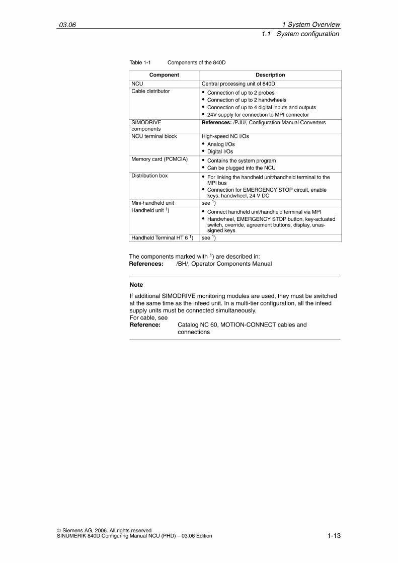
Table 1-1 Components of the 840D
Component Description
NCU Central processing unit of 840DCable distributor Connection of up to 2 probes
Connection of up to 2 handwheels Connection of up to 4 digital inputs and outputs 24V supply for connection to MPI connector
SIMODRIVE components
References: /PJU/, Configuration Manual Converters
NCU terminal block High-speed NC I/Os
Analog I/Os Digital I/Os
Memory card (PCMCIA) Contains the system program Can be plugged into the NCU
Distribution box For linking the handheld unit/handheld terminal to theMPI bus
Connection for EMERGENCY STOP circuit, enablekeys, handwheel, 24 V DC
Mini-handheld unit see 1)Handheld unit 1) Connect handheld unit/handheld terminal via MPI
Handwheel, EMERGENCY STOP button, key-actuatedswitch, override, agreement buttons, display, unas-signed keys
Handheld Terminal HT 6 1) see 1)
The components marked with 1) are described in:References: /BH/, Operator Components Manual
Note
If additional SIMODRIVE monitoring modules are used, they must be switchedat the same time as the infeed unit. In a multi-tier configuration, all the infeedsupply units must be connected simultaneously.For cable, seeReference: Catalog NC 60, MOTION-CONNECT cables and
connections
1 System Overview
03.061.1 System configuration
1-14© Siemens AG, 2006. All rights reserved
SINUMERIK 840D Configuring Manual NCU (PHD) – 03.06 Edition
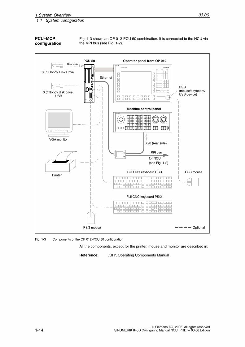
Fig. 1-3 shows an OP 012-PCU 50 combination. It is connected to the NCU viathe MPI bus (see Fig. 1-2).
Operator panel front OP 012PCU 50
Full CNC keyboard PS/2
3.5” Floppy Disk Drive
PS/2 mouse
VGA monitor
Printer
Machine control panel
X20 (rear side)
MPI bus
Ethernet
for NCU(see Fig. 1-2)
Rear side
Optional
USB(mouse/keyboard/USB device)
* TEMP* POWER
SIEMENS
SINUMERIK
USB mouse Full CNC keyboard USB
3.5” floppy disk drive, USB
Fig. 1-3 Components of the OP 012-PCU 50 configuration
All the components, except for the printer, mouse and monitor are described in:
Reference: /BH/, Operating Components Manual
PCU–MCP configuration
1 System Overview

03.061.1 System configuration
1-15© Siemens AG, 2006. All rights reservedSINUMERIK 840D Configuring Manual NCU (PHD) – 03.06 Edition
The following tables show the possible combinations of software and hardware:
Table 1-2 Software - hardware combination options for NCU 5xx.3 to SW 6.4
NCU system software NCU hardware
Designation Order No. 561.3 571.3 572.3 573.3
NCU system software 2 axeson PC card, Export 840DE
6FC5250-PX10-AH – –
NCU system software 6 axeson PC card, Export 840DE
6FC5250-BX10-AH – – –
NCU system software 12 axeson PC card
C Standard 840D Export 840DE
6FC5250-BX30-AH
6FC5250-BY30-AH
––
––
NCU system software 12 axeson PC card, standard 840Dincl. software version-specific additional functions
6FC5270-BX30-AH – –
NCU system software 31 axeson PC card
Standard 840D Export 840DE
6FC5250-AX30-AH
6FC5250-AY30-AH
––
––
NCU system software 31 axeson PC card, standard 840Dincl. software version-specific additional functions
6FC5270-AX30-AH
6FC5270-AX31-AH
6FC5270-AX32-AH
– –
combination possible; – combination not possible
Table 1-3 Combination possibilities for software and hardware for NCU 5xx.4 and NCU 5xx.5, SW 6.5 or higher
NCU hard-are
NCU system softwareware
2 axes 6 axes 12 axes 31 axes
561.4/.5 max. 2 out of 2 axes,max. 2 channels
max. 2 out of 2 axes,max. 2 channels
max. 2 out of 2 axes,max. 2 channels
max. 2 out of 2 axes,max. 2 channels
571.4/.5 max. 2 out of 2 axes,max. 2 channels
max. 6 out of 31 axes,max. 2 channels
max. 6 out of 31 axes,max. 2 channels
max. 6 out of 31 axes,max. 2 channels
572.4/.5 max. 2 out of 2 axes, max. 6 out of 31 axes, max. 12 out of 31 axes, max. 31 out of 31 axes,,max. 2 channels
,max. 2 channels
,max. 2 channels *)
,max. 10 channels
573.4/.5 max. 2 out of 2 axes,max. 2 channels
max. 6 out of 31 axes,max. 2 channels
max. 12 out of 31 axes,max. 2 channels *)
max. 31 out of 31 axes,max. 10 channels
*) for SW 7.2 or higher: max. 4 channels
SW – HWcombinations
1 System Overview

03.061.2 Labels and stickers
1-16© Siemens AG, 2006. All rights reserved
SINUMERIK 840D Configuring Manual NCU (PHD) – 03.06 Edition
1.2 Labels and stickers
In case of technical queries or service, please quote all data on the rating plateto the local SIEMENS office responsible for your equipment.
One of the following labels is attached to the components and modules:
Example: Component number: 570 573.9001.00Product version: B (last cross)
AB
Example: Component name: NCU 573.4MLFB: 6FC5357-0BB34-0AE0Component number: GWE-570038963520Version F (printed)
Example: Component name: NCU boxMLFB: 6FC5247-0AA00-0AA2Component number: GWE-570038901611Version H (printed)
PCBs with screenprinting
NCU
NCU box
1 System Overview

03.061.3 Non-Siemens keyboards
1-17© Siemens AG, 2006. All rights reservedSINUMERIK 840D Configuring Manual NCU (PHD) – 03.06 Edition
1.3 Non-Siemens keyboards
When standard PC keyboards are used, ensure that they have a CE symboland correspond to industrial requirements. Otherwise, there may be problemswith the PC keyboard.
If you encounter problems, contact the relevant regional office.
Standard PC keyboard
1 System Overview
03.061.3 Non-Siemens keyboards
1-18© Siemens AG, 2006. All rights reserved
SINUMERIK 840D Configuring Manual NCU (PHD) – 03.06 Edition
1 System Overview
Notes

2-19© Siemens AG, 2006. All rights reservedSINUMERIK 840D Configuring Manual NCU (PHD) – 03.06 Edition
Connection Conditions
2.1 Secondary electrical conditions
The controller is tested for compliance with the environmental conditions speci-fied below. Fault-free operation is only ensured if:
These environmental conditions are maintained when storing, transportingand operating the equipment,
Original components and spare parts are used. This applies in particular tothe use of specified cables and plug connectors,
The equipment has been correctly mounted/installed.
!Danger
The equipment may not be commissioned until it has been clearly identifiedthat the machine in which the controller is installed is in full conformance withthe specifications in EC Machinery Directive 98/37/EC.
The connection conditions must be carefully maintained for the complete sys-tem. Please contact your local Siemens office or representative for any assis-tance.
Compliance withthe connection conditions
Assistance andsupport
2
03.062.1 Secondary electrical conditions
2-20© Siemens AG, 2006. All rights reserved
SINUMERIK 840D Configuring Manual NCU (PHD) – 03.06 Edition
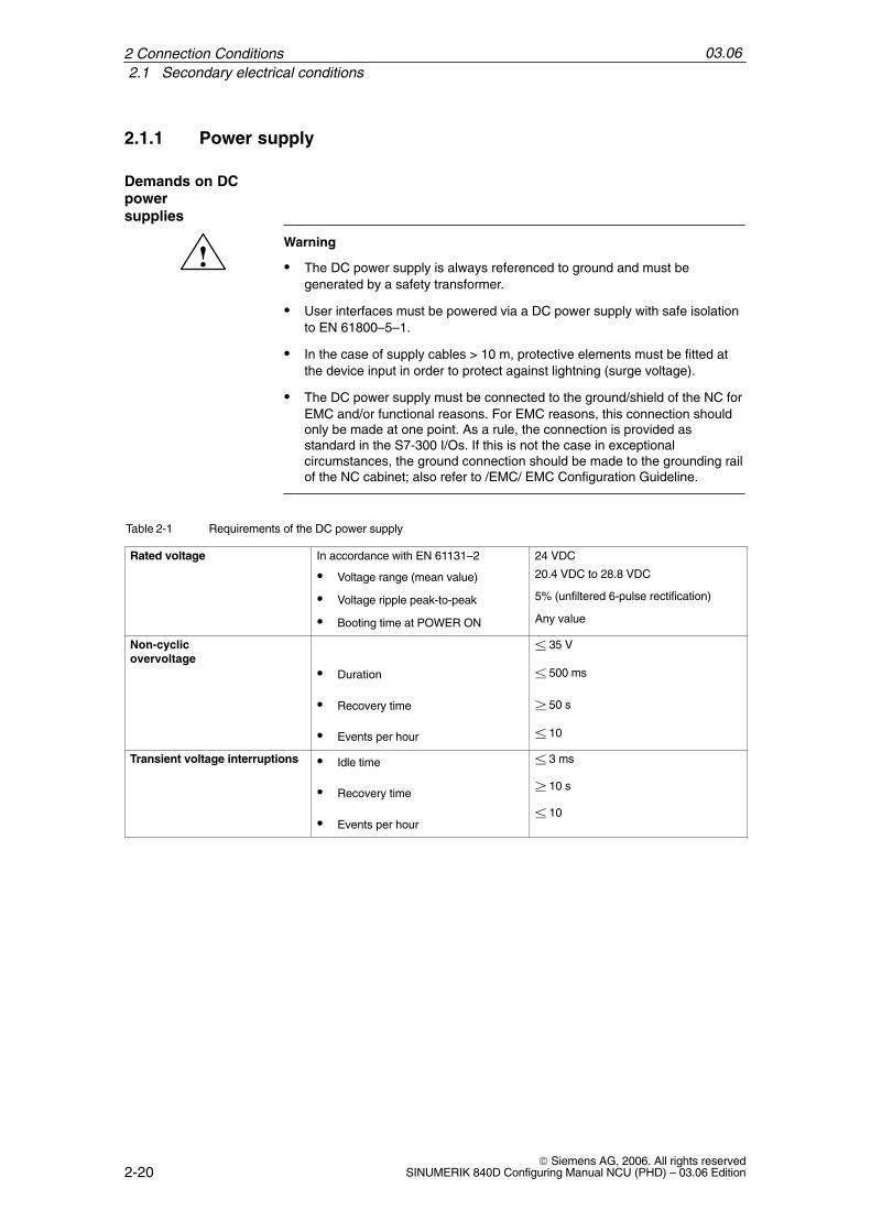
2.1.1 Power supply
!Warning
The DC power supply is always referenced to ground and must begenerated by a safety transformer.
User interfaces must be powered via a DC power supply with safe isolationto EN 61800–5–1.
In the case of supply cables > 10 m, protective elements must be fitted atthe device input in order to protect against lightning (surge voltage).
The DC power supply must be connected to the ground/shield of the NC forEMC and/or functional reasons. For EMC reasons, this connection shouldonly be made at one point. As a rule, the connection is provided asstandard in the S7-300 I/Os. If this is not the case in exceptionalcircumstances, the ground connection should be made to the grounding railof the NC cabinet; also refer to /EMC/ EMC Configuration Guideline.
Table 2-1 Requirements of the DC power supply
Rated voltage In accordance with EN 61131–2
Voltage range (mean value)
Voltage ripple peak-to-peak
Booting time at POWER ON
24 VDC
20.4 VDC to 28.8 VDC
5% (unfiltered 6-pulse rectification)
Any value
Non-cyclicovervoltage
Duration
Recovery time
Events per hour
35 V
500 ms
50 s
10
Transient voltage interruptions Idle time
Recovery time
Events per hour
3 ms
10 s
10
Demands on DCpower supplies
2 Connection Conditions

03.062.1 Secondary electrical conditions
2-21© Siemens AG, 2006. All rights reservedSINUMERIK 840D Configuring Manual NCU (PHD) – 03.06 Edition
2.1.2 Safe isolation to EN 61800–5–1
The complete system includes user interfaces (UIs) and interfaces for servicing,startup and maintenance.
UIs are all the interfaces that are freely accessible to the machine operator wi-thout the need for tools or aids. These user interfaces are designed with safeisolation to EN 61800–5–1.
!Danger
The interfaces for servicing, start-up and maintenance purposes are providedwithout safe isolation.
If necessary, these interfaces can be isolated safely using a supplementaryadapter (insulation voltage 230 V AC). Although these adapters are not includedin the Siemens scope of delivery, you can buy these parts from your localdealer, who will be happy to advise you.
!Danger
Safe isolation can only be ensured if the system configuration specified belowis strictly adhered to. When mounting additional components (e.g., S7-300 FM,IP) with a UI, please make sure that the UI has basic insulation for at least230 V AC.
End user interfaces (UI)
Interfaces forservicing, startupand maintenance
2 Connection Conditions

03.062.1 Secondary electrical conditions
2-22© Siemens AG, 2006. All rights reserved
SINUMERIK 840D Configuring Manual NCU (PHD) – 03.06 Edition
Basic insulation Safety isolation
G
3ph 400 V AC
N
Housing/shield
840D / 611 digital
1
2
3
4
10
44
5
6
11
S7-300 I/Os
MSTT/MCPPCU
9
24 V
8
Person
G
7
10
11
Terminalblock
11
ÎÎMotor
5
4
HHU/ HT 6
Distribution box
Fig. 2-1 Safe isolation to EN 61800–5–1
Fig. 2-1 shows the various electrical potentials of the 840D/611D/S7-300 sys-tem. Legend:
1. Floating power supply of the SIMODRIVE electronics unit with 230 V AC basic insulation.
2. Floating transistor triggers for the three-phase rectifier bridge with 230 V ACbasic insulation.
3. Floating transistor triggers for each axis of the three-phase inverter bridgewith 230 V AC basic insulation.
4. Floating signal connection from the NCU to the PCU or HHU with 230 V ACbasic insulation.
5. Non-floating signal connection between NCU and I/O devices.
6. Non-floating end user interface with protective separation for 230 VACthrough interfaces 1 to 4 and 7.
7. Protectively separated 5 V DC power supply, fed from a protectively sepa-rated 24 V DC supply.
8. 24 V DC power supply unit for external devices and for the machine adapta-tion control according to applicable standards in the form of a PELV (Protec-tive Extra Low Voltage) circuit featuring safe isolation.
9. Floating interfaces to the machine (not accessible to the end user).
10. Floating signal interfaces directly accessible to the end user (e.g., V.24). Forthese interfaces, you must always make sure that there is either safe isola-tion with respect to the line supply voltage or that there are two basic insula-tion levels, for 230 V AC each.
11. 5 V DC power supply with basic insulation, fed from a safely-isolated 24 V DC supply.
2 Connection Conditions

03.062.1 Secondary electrical conditions
2-23© Siemens AG, 2006. All rights reservedSINUMERIK 840D Configuring Manual NCU (PHD) – 03.06 Edition
2.1.3 Grounding concept
The SINUMERIK 840D system consists of a number of individual components,each of which must comply with the appropriate EMC and safety standards. Theindividual system components are:
NCU box
Machine control panel MCP
Keyboard
Operator panels (operator panel front + PCU/TCU)
NCU terminal block
Distributor box and handheld unit
S7-300 I/O with IM 361 interface module
Single I/O module
The NCU box is a 50 mm wide cassette that is integrated into the infeed/regen-erative feedback (I/RF) unit, FSD and MSD.
The individual modules are attached to a metal cabinet panel by means ofscrews. Make sure that near the screws a low-impedance contact of the NCUbox with the cabinet wall can be made. Insulating paints at the contact pointmust be removed. The electronic grounding points of the modules are intercon-nected via the device and drive bus and at the same time conducted to theX131 terminal of the I/RF module.
The ground and module ground M should be connected at the power supplyterminal of the IM 361. Further, for the EFP, “SHIELD” and “M24” must be con-nected in connector X1.
2 Connection Conditions

03.062.1 Secondary electrical conditions
2-24© Siemens AG, 2006. All rights reserved
SINUMERIK 840D Configuring Manual NCU (PHD) – 03.06 Edition
Operator panel front
ÏÏÏÏÏÏÏÏÏ
SL SL
Powerelectronics
Machine bed
Grounding bar
Central ground connection conductor/protectiveconductor
PAG
G
PA
Gatingelectronics
NCU
SL in the motor cable
Machine control panel
S7-300 peripherals/single I/O module
PA
MB
MB: Shielded signal cable with reference ground
PA: Equipotential bonding conductorSL: Protective conductor
M: MotorG: Encoders
– Ground (frame) –
SL
Terminalblock
SL
Distribu–tion box
Cross-sections (mm2) 10
Line supply conn. S SL minimumS 1616 S 35S 35
S 16 S/2
MB
IM 361
PCU/TCU
MB
Fig. 2-2 Grounding concept
References: /EMC/ EMC Configuring Guidelines
2.1.4 RI suppression measures
In addition to the protective grounding of system components, special precau-tions must be taken to ensure safe, fault-free operation of the system. Thesemeasures include shielded signal cables, special equipotential bonding, isola-tion, and shielding measures.
To ensure safe, interference-free operation of the installation, it is essential touse the cables specified in the individual diagrams.
For digital signal transmission, the shield must have a conductive connection atboth sides of the housing.
Exception:
Standard shielded cables grounded on only one side can be used for devicesfrom other manufacturers (printers, programming devices, etc.).
Shieldedsignal cables
2 Connection Conditions

03.062.1 Secondary electrical conditions
2-25© Siemens AG, 2006. All rights reservedSINUMERIK 840D Configuring Manual NCU (PHD) – 03.06 Edition
These external devices may not be connected to the control during normal op-eration. However, if the system cannot be operated without them, then the cableshields must be connected at both ends. Furthermore, the external device mustbe connected to the control via an equipotential bonding cable.
Definition:
Signal cables (example)
– Data cables (MPI, sensor cables, etc.)
– Binary inputs and outputs
– EMERGENCY OFF lines
Load cables (example)
– Low-voltage supply cables (230 V AC, +24 V DC etc.)
– Supply cables to contactors (primary and secondary circuit)
In order to achieve the best possible noise immunity of the complete system(control, power module, machine), the following EMC measures must be care-fully observed:
Signal cables and load cables must be routed at the greatest possible dis-tance from one another.
If necessary, signal and load cables may cross one another (if possible, atan angle of 90°), but must never be laid close or parallel to one another.
Only cables provided by the manufacturer should be used as signal cablesfrom and to the NCU.
Signal cables may not be routed close to strong external magnetic fields(e.g. motors and transformers).
Pulse-carrying HC/HV cables must always be laid completely separatelyfrom all other cables.
If signal lines cannot be routed a sufficient distance away from other cables,they must be installed in grounded cable ducts (metal).
The clearance (interference injection area) between the following lines mustbe kept to a minimum:
– Signal line and electrical circuit signal line (twisted)
– Signal line and associated equipotential bonding conductor
– Equipotential bonding conductor and PE conductor (routed together)
!Important
For further notes on interference suppression measures and the connection ofshielded cables, please refer to References: /EMC/ EMC Configuring Guidelines
Cable definitions
Rules for routingcables
2 Connection Conditions
03.062.2 Climatic and mechanical environmental conditions
2-26© Siemens AG, 2006. All rights reserved
SINUMERIK 840D Configuring Manual NCU (PHD) – 03.06 Edition
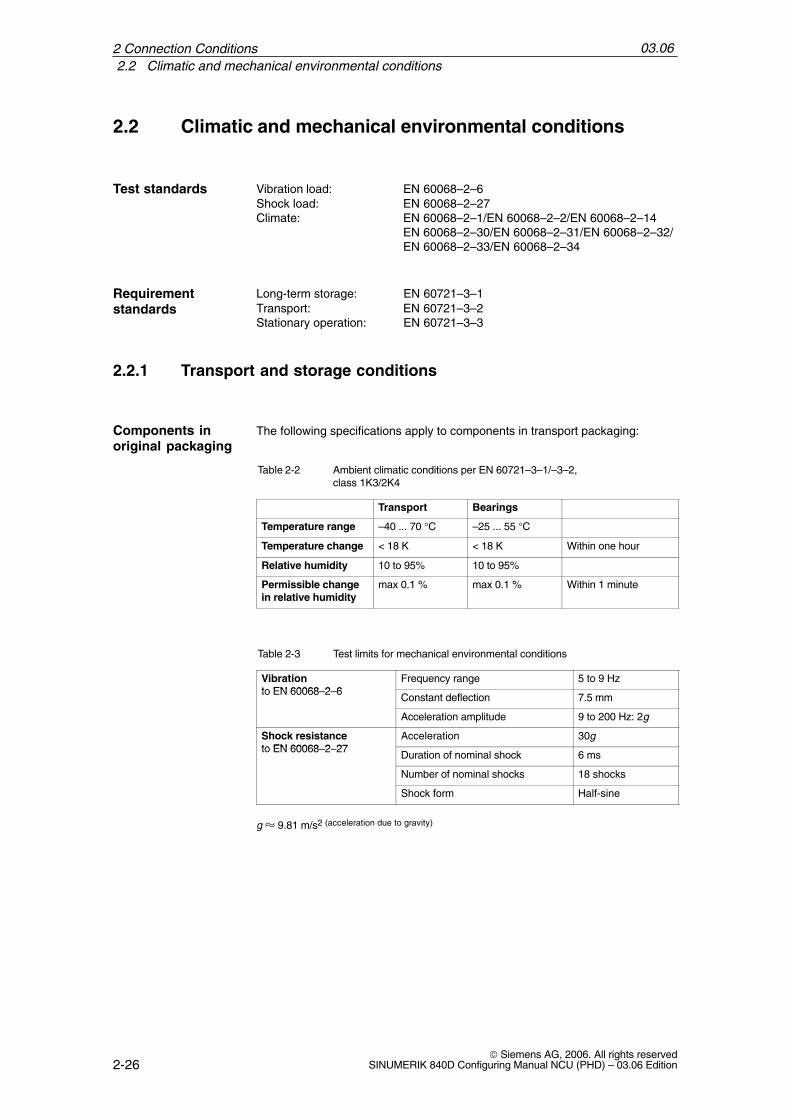
2.2 Climatic and mechanical environmental conditions
Vibration load: EN 60068–2–6Shock load: EN 60068–2–27Climate: EN 60068–2–1/EN 60068–2–2/EN 60068–2–14
EN 60068–2–30/EN 60068–2–31/EN 60068–2–32/EN 60068–2–33/EN 60068–2–34
Long-term storage: EN 60721–3–1Transport: EN 60721–3–2Stationary operation: EN 60721–3–3
2.2.1 Transport and storage conditions
The following specifications apply to components in transport packaging:
Table 2-2 Ambient climatic conditions per EN 60721–3–1/–3–2, class 1K3/2K4
Transport Bearings
Temperature range –40 ... 70 °C –25 ... 55 °C
Temperature change < 18 K < 18 K Within one hour
Relative humidity 10 to 95% 10 to 95%
Permissible changein relative humidity
max 0.1 % max 0.1 % Within 1 minute
Table 2-3 Test limits for mechanical environmental conditions
Vibrationto EN 60068 2 6
Frequency range 5 to 9 Hzto EN 60068–2–6
Constant deflection 7.5 mm
Acceleration amplitude 9 to 200 Hz: 2g
Shock resistanceto EN 60068 2 27
Acceleration 30gto EN 60068–2–27
Duration of nominal shock 6 ms
Number of nominal shocks 18 shocks
Shock form Half-sine
g 9.81 m/s2 (acceleration due to gravity)
Test standards
Requirement standards
Components inoriginal packaging
2 Connection Conditions

03.062.2 Climatic and mechanical environmental conditions
2-27© Siemens AG, 2006. All rights reservedSINUMERIK 840D Configuring Manual NCU (PHD) – 03.06 Edition
Backup batteries must only be transported in the original packaging. No specialauthorization is required to ship backup batteries. The lithium content is approxi-mately 300 mg.
Note
The backup battery is classified as a hazardous substance, Class 9, inaccordance with the relevant air-freight transportation regulations.
!Danger
Incorrect handling of backup batteries can lead to a risk of ignition, explosionand combustion. The stipulations of EN 60086-4, in particular regardingavoidance of mechanical or electrical tampering of any kind, must be compliedwith.
For more information on handling batteries, see Chapter 8.1.
2.2.2 Operating conditions
If the specified values cannot be maintained, then a heat exchanger or air con-ditioner must be provided.
Table 2-4 Climatic environmental conditions to EN 60721–3–3, Class 3K3
Temperature range 0 to 55 °C
Temperature change max. 0.5 K Within 1 minute
Relative humidity 5 to 90 %
Permissible change in therelative air humidity
max. 0.1% Within 1 minute
Moisture condensationand ice formation
Not permitted
Dripping water, spray,splash water, water jets
Not permitted
Supply air Without caustic gases, dusts and oils
Air pressure 1060 to 920 kPa 0 to 1000 meters above mean sealevel
Derating At altitudes of 1000 to 4000 m above SL, the upper limittemperature is to be lowered by 3.5 °C/500 m.
Shipment of backup batteries
Climatic environmentalconditions
2 Connection Conditions
03.062.2 Climatic and mechanical environmental conditions
2-28© Siemens AG, 2006. All rights reserved
SINUMERIK 840D Configuring Manual NCU (PHD) – 03.06 Edition
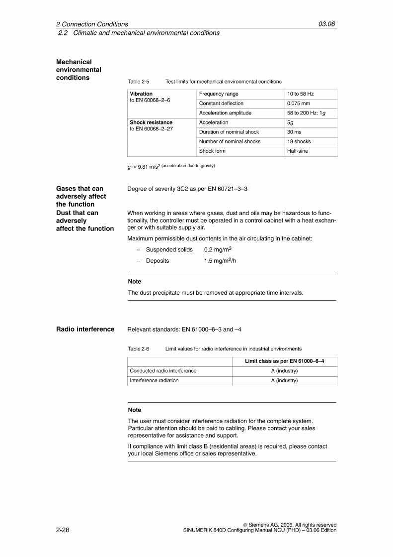
Table 2-5 Test limits for mechanical environmental conditions
Vibrationt EN 60068 2 6
Frequency range 10 to 58 Hzto EN 60068–2–6
Constant deflection 0.075 mm
Acceleration amplitude 58 to 200 Hz: 1g
Shock resistancet EN 60068 2 27
Acceleration 5gto EN 60068–2–27
Duration of nominal shock 30 ms
Number of nominal shocks 18 shocks
Shock form Half-sine
g 9.81 m/s2 (acceleration due to gravity)
Degree of severity 3C2 as per EN 60721–3–3
When working in areas where gases, dust and oils may be hazardous to func-tionality, the controller must be operated in a control cabinet with a heat exchan-ger or with suitable supply air.
Maximum permissible dust contents in the air circulating in the cabinet:
– Suspended solids 0.2 mg/m3
– Deposits 1.5 mg/m2/h
Note
The dust precipitate must be removed at appropriate time intervals.
Relevant standards: EN 61000–6–3 and –4
Table 2-6 Limit values for radio interference in industrial environments
Limit class as per EN 61000–6–4
Conducted radio interference A (industry)
Interference radiation A (industry)
Note
The user must consider interference radiation for the complete system.Particular attention should be paid to cabling. Please contact your salesrepresentative for assistance and support.
If compliance with limit class B (residential areas) is required, please contactyour local Siemens office or sales representative.
Mechanical environmentalconditions
Gases that canadversely affectthe functionDust that canadversely affect the function
Radio interference
2 Connection Conditions

03.062.3 MPI/OPI network rules
2-29© Siemens AG, 2006. All rights reservedSINUMERIK 840D Configuring Manual NCU (PHD) – 03.06 Edition
2.3 MPI/OPI network rules
The following devices can be interconnected across the MPI bus:
NCU
PCU
HT 6
HHU
MSTT/MCP
The MPI interconnecting cables are available in different lengths.
When installing a network, observe the following basic rules:
1. The MPI connection can be routed from one user to the next by plugging theMPI connector of the outgoing cable onto the MPI connector of the incomingcable.
2. The bus line must be terminated at both ends. To do this, enable the termi-nating resistor in the MPI connector of the first and last node and disable theremaining terminating resistors (see Fig. 2-3).
Note
Only two inserted terminating resistors are permitted.
In the case of the HHU/HT 6, bus terminating resistors are permanentlyintegrated in the device.
3. At least 1 terminal must be supplied with 5 V.This is done by connecting an MPI connector with the terminating resistorconnected to an energized device.
Note
The NCU must be located at the end of the connection.
4. Drop cables (feeder cable from bus segment to node) should be as short aspossible.
Note
Unused spurs must be removed.
5. Every MPI node must first be connected and then activated.When disconnecting an MPI node, first deactivate the connection and thenremove the connector.
6. A maximum of two of the HHU and HT 6 components can be connected foreach bus segment.
Use
Networkinstallations
2 Connection Conditions

03.062.3 MPI/OPI network rules
2-30© Siemens AG, 2006. All rights reserved
SINUMERIK 840D Configuring Manual NCU (PHD) – 03.06 Edition
Another possibility is two identical components, provided they have differentnode addresses.For setting the addresses (also see corresponding component section):
– HHU: Via DIP switch or display (see “Handheld unit” section),
– For HT 6, by adapting the address before commissioning (refer to Oper-ating Components “Handheld Terminal HT 6”).
No bus terminating resistors may be inserted at the distributor boxes of anHHU or HT 6 (refer to the note on item 2.)
If required, more than one HHU/HT 6 can be connected to a bus segmentusing intermediate repeaters.
7. The following cable lengths for MPI or OPI for standard use without repeatermay not be exceeded:
MPI (187.5 kbaud): Max. total cable length is 1000 m
OPI (1.5 Mbaud): Max. total cable length is 200 m.
ON
Terminating resistor
OFF ON
ON
46 46
55
Fig. 2-3 MPI connector
Reference: Catalog IK PI – Industrial Communication for Automation and Drives
2 Connection Conditions

3-31© Siemens AG, 2006. All rights reservedSINUMERIK 840D Configuring Manual NCU (PHD) – 03.06 Edition
Structure and Installation
3.1 Structure of the SINUMERIK 840D
The SINUMERIK 840D consists of two components:
1. NCU box (sheet metal housing with a combined battery/fan slide-in module)for housing the NCU module.
2. NCU module (Numeric Control Unit)
NCU module
NCU box
Fig. 3-1 Components of the SINUMERIK 840D
SINUMERIK 840D
3
03.063.2 Installation of the SINUMERIK 840D
3-32© Siemens AG, 2006. All rights reserved
SINUMERIK 840D Configuring Manual NCU (PHD) – 03.06 Edition
3.2 Installation of the SINUMERIK 840D
You need the following tool to assembly the SINUMERIK 840D:
Screwdriver for slot-head screws sizes 0 and 1
Screwdriver for Torx screws M4 and M5
Note
The NCU is exclusively intended for installation in ESD-protected zones. TheESD interference immunity limits relevant to CE compliance can only beachieved by installation in a cabinet. Make contact only while taking suitableESD protective measures (see ESD information in the preface).
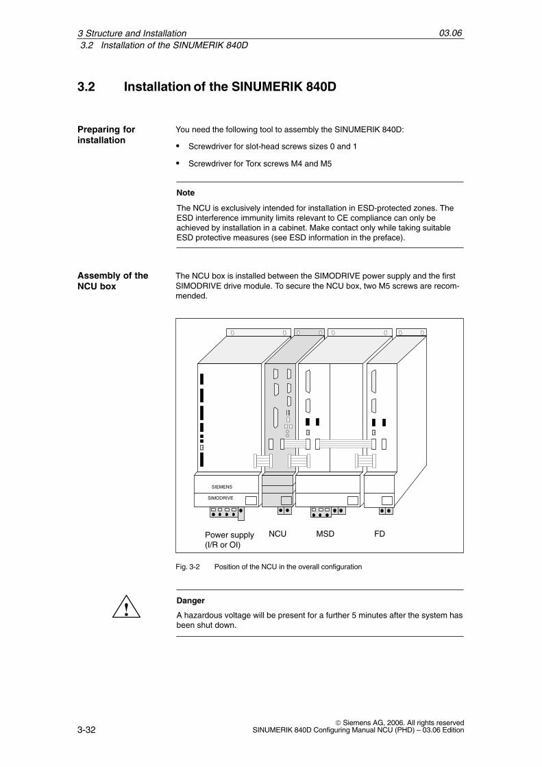
The NCU box is installed between the SIMODRIVE power supply and the firstSIMODRIVE drive module. To secure the NCU box, two M5 screws are recom-mended.
SIMODRIVE
NCU MSDPower supply(I/R or OI)
FD
SIEMENS
Fig. 3-2 Position of the NCU in the overall configuration
!Danger
A hazardous voltage will be present for a further 5 minutes after the system hasbeen shut down.
Preparing forinstallation
Assembly of theNCU box
3 Structure and Installation

03.063.2 Installation of the SINUMERIK 840D
3-33© Siemens AG, 2006. All rights reservedSINUMERIK 840D Configuring Manual NCU (PHD) – 03.06 Edition
1. Remove the plastic cover over the DC link busbars by loosening it with a flatscrewdriver in the gap on the top and then folding it forward and down.
2. Remove the DC link busbars at the module to the right of the NCU box.
3. Now mount the DC link busbars from the accessory kit of the NCU box be-tween the power module and the first drive module. Use the screws locatedon the modules (observe tightening torque, M4: 1.8 Nm, M5: 3 Nm).
4. Place the cover into the matching cut-outs with the plastic lugs facing down-ward and close the DC link by folding the cover backward until the topsidelatch clicks.
The NCU module is secured when it clicks into the NCU box.
In order to guarantee the vibration resistance, both slotted screws (1) must betightened (see Fig. 3-3).
The battery/fan module is delivered completely assembled with the NCU box.
Battery/fan slide-in module
Memory card
PE conductor connection
1
1
NCU module
NCU box
End-to-endDC linkbusbars
Fig. 3-3 Installation of the NCU module in the NCU box
Mounting the DClink busbar
Inserting the NCU
3 Structure and Installation

03.063.2 Installation of the SINUMERIK 840D
3-34© Siemens AG, 2006. All rights reserved
SINUMERIK 840D Configuring Manual NCU (PHD) – 03.06 Edition
Certain distances must be maintained with regard to cable routing and openventilation when mounting the NCU box.
A
A
Space for exhaust air
Space for supply air 24.823
208
24.8
49.6130
100
443
127
20
100
466
480
8
Fig. 3-4 NCU cassette for Sinumerik 840D, dimensional drawing and installation instructions
Maintainingdistances
3 Structure and Installation

03.063.2 Installation of the SINUMERIK 840D
3-35© Siemens AG, 2006. All rights reservedSINUMERIK 840D Configuring Manual NCU (PHD) – 03.06 Edition
200
ÎÎÎÎÎÎÎÎ
ÏÏÏÏÏÏÏÏÏÏÏÏ
ÎÎÎÎ
ÏÏÏÏÏÏ
Cooling clearance
60
Cooling clearance
Cooling clearance
60
60
288
Cooling clearance
Variant 1 Variant 2
60
100
100
100
80
20 20
80 100
Fig. 3-5 Cable routing and ventilation space when mounting modules
For installation, it is recommended that the front plate at the link module be re-moved and then reattached after the installation.
Mounting the link module
3 Structure and Installation

03.063.2 Installation of the SINUMERIK 840D
3-36© Siemens AG, 2006. All rights reserved
SINUMERIK 840D Configuring Manual NCU (PHD) – 03.06 Edition
3 Structure and Installation
Notes

4-37© Siemens AG, 2006. All rights reservedSINUMERIK 840D Configuring Manual NCU (PHD) – 03.06 Edition
Description of the NCU
4.1 Components
The components of the SINUMERIK 840D are compatible with the module se-ries SIMODRIVE 611D. The 840D is operated with the power supply of SIMODRIVE 611 and the SIMODRIVE 611D drive modules.
The NCU module (Numeric Control Unit) is the CPU of the SINUMERIK 840D. Ittakes over all the CNC, PLC and communication tasks. It is available in variousperformance variants:
Table 4-1 Components from the NCU 5xx.3 series:
NCU Order no. (MLFB) Processor CNC user memory
min. / max.
PLC PLC memory
min. / max.
Front plate
Fanbox
561.3 6FC5356-0BB11-0AE1
Intel 486 DX4100 MHz
0.25/1.5 MB PLC 315-2DP 96 / 288 KB Type 1 No
561.3 6FC5356-0BB13-0AA1
Celeron400 MHz
0.5/2.5 MB *) PLC 315-2DP 96 / 288 KB Type 3 No
571.3 6FC5357-0BB11-0AE1
Intel 486 DX4100 MHz
0.25/1.5 MB PLC 315-2DP 96 / 288 KB Type 1 No
571.3 6FC5357-0BB13-0AA1
Celeron 400 MHz
0.5/2.5 MB *) PLC 315-2DP 96 / 288 KB Type 3 No
572.3 6FC5357-0BB22-0AE0
AMD K6-2233 MHz
0.25/1.5 MB PLC 315-2DP 96 / 288 KB Type 2 No
572.3 6FC5357-0BB23-0AA0/1
Celeron 400 MHz
0.5/2.5 MB *) PLC 315-2DP 96 / 288 KB Type 3 No
573.3 6FC5357-0BB33-0AE2
Pentium III500 MHz
2.5/2.5 MB *) PLC 315-2DP 96 / 288 KB Type 3 Yes
573.3 6FC5357-0BB33-0AE3
Celeron 650 MHz
2.5/2.5 MB *) PLC 315-2DP 96 / 288 KB Type 3 No
573.3 6FC5357-0BB33-0AA0/1
Celeron 650 MHz
2.5/2.5 MB *) PLC 315-2DP 96 / 288 KB Type 3 No
*) With technological cycles and measuring cycles, max. 1.5 MB available for users. With ShopMill/ShopTurn 1.2 MBavailable to users in the basic configuration and no other CNC user memory options are possible.
Configuration
NCU module
4

03.064.1 Components
4-38© Siemens AG, 2006. All rights reserved
SINUMERIK 840D Configuring Manual NCU (PHD) – 03.06 Edition
Table 4-2 Components from the NCU 5xx.4 series:
NCU Order no. (MLFB) Processor CNC user memory
min. / max.
PLC PLC memory
min. / max.
Front plate
Fanbox
561.4 6FC5356-0BB12-0AE0
AMD K6-2233 MHz
0.5/2.5 MB *) PLC 314C-2DP 96 / 480 KB Type 2 No
561.4 6FC5356-0BB14-0AA0
Celeron 400 MHz
0.5/3 MB *) PLC 314C-2DP 96 / 480 KB Type 3 No
571.4 6FC5357-0BB12-0AE0
AMD K6-2233 MHz
0.5/2.5 MB *) PLC 314C-2DP 96 / 480 KB Type 2 No
571.4 6FC5357-0BB14-0AA0
Celeron 400 MHz
0.5/3 MB *) PLC 314C-2DP 96 / 480 KB Type 3 No
572.4 6FC5357-0BB23-0AE0
AMD K6-2233 MHz
0.5/2.5 MB *) PLC 314C-2DP 96 / 480 KB Type 2 No
572.4 6FC5357-0BB24-0AA0
Celeron 400 MHz
0.5/3 MB *) PLC 314C-2DP 96 / 480 KB Type 3 No
573.4 6FC5357-0BB34-0AE0
Pentium III500 MHz
2.5/2.5 MB *) PLC 314C-2DP 96 / 480 KB Type 3 Yes
573.4 6FC5357-0BB34-0AE1
Celeron 650 MHz
2.5/2.5 MB *) PLC 314C-2DP 96 / 480 KB Type 3 No
573.4 6FC5357-0BB34-0AA0
Celeron 650 MHz
2.5/3 MB *) PLC 314C-2DP 96 / 480 KB Type 3 No
*) With technological cycles and measuring cycles, max. 1.5 MB available for users. With ShopMill/ShopTurn 1.2 MBavailable to users in the basic configuration and no other CNC user memory options are possible.
Table 4-3 Components from the NCU 5xx.5 series:
NCU Order no. (MLFB) Processor CNC user memory
min. / max.
PLC PLC memory
min. / max.
Frontpanel
Fanbox
561.5 6FC5356-0BB15-0AA0
Celeron 400 MHz
3 **) / 6 MB PLC 317-2DP 128 / 768 KB Type 3 No
571.5 6FC5357-0BB15-0AA0
Celeron 400 MHz
3 **) / 6 MB PLC 317-2DP 128 / 768 KB Type 3 No
572.5 6FC5357-0BB25-0AA0
Celeron 650 MHz
3 **) / 6 MB PLC 317-2DP 128 / 768 KB Type 3 No
573.5 6FC5357-0BB35-0AE0
Pentium III933 MHz
3 **) / 6 MB PLC 317-2DP 128 / 768 KB Type 3 No
573.5 6FC5357-0BB35-0AA0
Pentium III 933 MHz
3 **) / 6 MB PLC 317-2DP 128 / 768 KB Type 3 No
**) Available to the user in the basic configuration: – with technological cycles and measuring cycles max. 1.5 MB– with ShopMill/ShopTurn 1.2 MB
Features of the NCU modules:
Standard PCMCIA card
4 High-speed NC inputs and 4 rapid NC outputs
2 Measuring pulse inputs
2 Handwheel inputs
Voltage and temperature monitoring
4 Description of the NCU
03.064.1 Components
4-39© Siemens AG, 2006. All rights reservedSINUMERIK 840D Configuring Manual NCU (PHD) – 03.06 Edition
The NCU box is the module rack of the NCU module and consists of:
NC rack assembly with cable distributor
Battery/fan slide-in module
Sheet metal housing with integrated guide bars for accommodating the NCU and the fan/battery slide-in modules and power supply unit
Order number: 6FC5247-0AA00-0AA3
The fan box is absolutely required for the 573.3 (Pentium III) and 573.4 (Pen-tium III) NCUs. Mount the fan box to the NCU box if necessary.
Order number: 6FC5247-0AA30-0AA0
As a submodule of the NCU, the PLC module supports machine monitoring andrepresents a PLC-CPU that is compatible to the S7-300 family of products. Viathe P bus, three external lines can be connected for every eight S7-300 periph-eral modules.
Reference: Installation manual for setting up the S7-300: CPU
The COM module is a submodule of the NCU. It is used for communication withthe PCU and peripherals.
The driver module is a submodule of the NCU (...-...-0AEx). It forms the inter-face to the operator panel front, to the programming device, to the decentralizedperipherals and to S7-300 peripherals.
The NCU contains a plug-in unit for standard PCMCIA cards (PC card or NCcard), via which all flash cards of type II up to 8 MB storage capacity can beoperated.
The PCMCIA card serves as a bulk memory for the NC system software (NCcard).
In addition to the software upgrade, the PCMCIA card can also be used for se-ries start-up; see References: /IAD/ Commissioning Manual 840D
Caution
Plugging the PCMCIA card in and out while energized will cause data to belost!
NCU box
Fan box
PLC module
COM module187.5 kBd/1.5 MBd
Driver module187.5 kBd/1.5 MBd
PCMCIA card
4 Description of the NCU

03.064.1 Components
4-40© Siemens AG, 2006. All rights reserved
SINUMERIK 840D Configuring Manual NCU (PHD) – 03.06 Edition
The link module is a submodule of the NCU 573.3/4/5. If it is plugged in, youcan reach the interface via the front plate of the NCU (above X122).
The module allows synchronization and an additional data exchange betweenseveral NCU 573.3/4/5 in a group.
Order No.: 6FC5212-0AA01-1AA0
2.4 +0.4–1.4
163.
3
16.8
37.4
96.5
Fig. 4-1 Link submodule
Standard Profibus cable
Link module(option for NCU 573.3/4/5)
Link cable
4 Description of the NCU
03.064.2 Mounting
4-41© Siemens AG, 2006. All rights reservedSINUMERIK 840D Configuring Manual NCU (PHD) – 03.06 Edition
4.2 Mounting
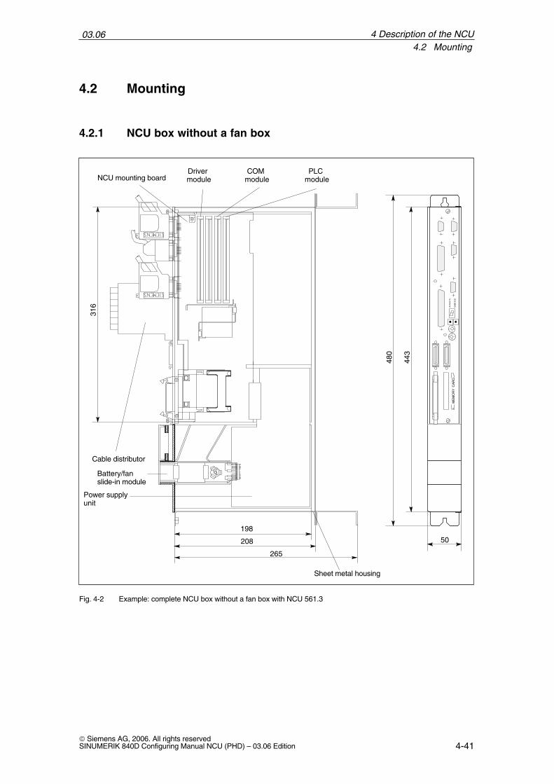
4.2.1 NCU box without a fan box
316
480
443
198
265
50
Battery/fan slide-in module
Power supply unit
Sheet metal housing
Driver module
COM module
PLC moduleNCU mounting board
Cable distributorM
EM
OR
Y C
AR
D
208
Fig. 4-2 Example: complete NCU box without a fan box with NCU 561.3
4 Description of the NCU
03.064.2 Mounting
4-42© Siemens AG, 2006. All rights reserved
SINUMERIK 840D Configuring Manual NCU (PHD) – 03.06 Edition
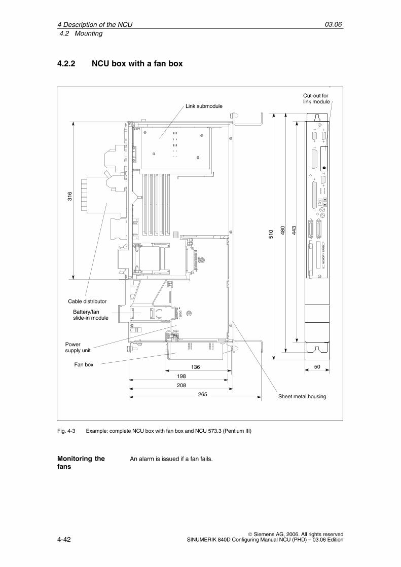
4.2.2 NCU box with a fan box
480
443
50
ME
MO
RY
CA
RD
198
265
208
316
136
510
Battery/fan slide-in module
Power supply unit
Cable distributor
Sheet metal housing
Fan box
Cut-out for link module
Link submodule
Fig. 4-3 Example: complete NCU box with fan box and NCU 573.3 (Pentium III)
An alarm is issued if a fan fails.Monitoring thefans
4 Description of the NCU

03.064.2 Mounting
4-43© Siemens AG, 2006. All rights reservedSINUMERIK 840D Configuring Manual NCU (PHD) – 03.06 Edition
1. Slide the back of the fan box into the locking mechanism on the NCU box.
Fan box
2. Push the front section into the guide until the spring locks.
Guide
For replacing the fan box
1. Apply pressure to the locking spring on the front section of the fan box and
2. Slide the fan box downward.
Mountingthe fan box
Replacement
4 Description of the NCU

03.064.2 Mounting
4-44© Siemens AG, 2006. All rights reserved
SINUMERIK 840D Configuring Manual NCU (PHD) – 03.06 Edition
Fan box
!Warning
Only trained personnel may replace a fan box. The regulations for handlingelectrostatic sensitive devices must be observed.
Completely switch off the system. Check that it is safely isolated from thesupply and safeguard against unauthorized switch-on.
4 Description of the NCU

03.064.3 NCU module interfaces
4-45© Siemens AG, 2006. All rights reservedSINUMERIK 840D Configuring Manual NCU (PHD) – 03.06 Edition
4.3 NCU module interfaces
The NCU module has the following interfaces:
Operating panel front interface X101 (MPI 1.5 MBaud, floating)
PROFIBUS DP X102 interface
SIMATIC S7 I/O bus X111 (P/C bus)
Link interface (option for NCU 573.3/4/5)
Connection for handwheel, sensor, NC-I/O X121 (cable distributor)
Interface for programming device X122 (MPI 187.5 KBaud, non-isolated)
SIMODRIVE 611D interface X130A (611D module and NCU terminal block)
Device bus connection X172
PCMCIA slot X173
Displays for faults, status, start-up
Operating elements for start-up, general reset, reset
Brief descriptionof the interfaces
4 Description of the NCU

03.064.3 NCU module interfaces
4-46© Siemens AG, 2006. All rights reserved
SINUMERIK 840D Configuring Manual NCU (PHD) – 03.06 Edition
For component assignments, see Section 4.1
SIMATIC interface
PG-MPI interface
I/O interface (cable distributor)
Various error and status LEDs(H1/H2)
7-segment display (H3)
RESET button (S1)NMI button (S2)
PLC start-up switch
Reserved
NCK start-up switch
SIMODRIVE 611D interface
PCMCIA slot (X173)
Device bus interface
ME
MO
RY
CA
RD
–X17
2
S3
X13
0B
X13
0A
–X12
1–X
111
S4
–X102–X101
–X112
–X122
RESET NMI
Operator panel front interface
Reserved for service
+5V
NF
CF
CB
CP
PR
PS
PF
PFO
−
PROFIBUS DP interface
Fig. 4-4 Front plate type 1
Interfaces,Operator Controlsand Displays
4 Description of the NCU

03.064.3 NCU module interfaces
4-47© Siemens AG, 2006. All rights reservedSINUMERIK 840D Configuring Manual NCU (PHD) – 03.06 Edition
SIMATIC interface
PG-MPI interface
I/O interface (cable distributor)
Various error and status LEDs(H1/H2)
7-segment display (H3)
RESET button (S1)
PLC start-up switch
NCK start-up switch
SIMODRIVE 611D interface
PCMCIA slot (X173)
Device bus interface
ME
MO
RY
CA
RD
–X17
2
S3
X13
0A
–X12
1–X
111
S4
–X102–X101
–X103
–X122
RESET
Operator panel front interface
Reserved
+5V
NF
CF
CB
CP
PR
PS
PF
PFO
T
PROFIBUS DP Interface
Fig. 4-5 Front plate type 2
4 Description of the NCU

03.064.3 NCU module interfaces
4-48© Siemens AG, 2006. All rights reserved
SINUMERIK 840D Configuring Manual NCU (PHD) – 03.06 Edition
SIMATIC interface
PG-MPI interface
I/O interface (cable distributor)
Various error and status LEDs(H1/H2)
7-segment display (H3)
RESET button (S1)
NMI button (S2)
PLC start-up switch
Reserved
NCK start-up switch
SIMODRIVE 611D interface
PCMCIA slot (X173)
Device bus interface
ME
MO
RY
CA
RD
–X17
2
S3
X13
0B
X13
0A
–X12
1–X
111
S4
–X102–X101
–X122
Operator panel front interface
POK
NF
CF
CB
CP
PR
PS
PF
PFO
DP
Slot for link module(blank plate)
PROFIBUS DP Interface
NM
IR
ES
ET
Fig. 4-6 Front plate type 3
4 Description of the NCU

03.064.3 NCU module interfaces
4-49© Siemens AG, 2006. All rights reservedSINUMERIK 840D Configuring Manual NCU (PHD) – 03.06 Edition
Operator panel front interface (MPI)
Connector name: X101Connector type: 9-pole sub D socket connectorMaximum cable length: 200 mSpecial features: Isolation (safe isolation)
Table 4-4 Pin assignments on connector X101
X101
Pin Name Type Pin Name Type
1 Not assigned 6 2P5 VO
2 Not assigned 7 Not assigned
3 RS_OPI B 8 XRS_OPI B
4 RTSAS_BTSS O 9 RTSPG_BTSS I
5 2M VO
Signal names
XRS_BTSS, RS_BTSS differential RS485 data – BTSSRTSAS_BTSS Request to Send AS – BTSSRTSPG_BTSS Request to Send PG – BTSS2M Signal Ground, isolated2P5 + 5 V, isolatedP24ext, M24ext 24 V supply voltage
Signal type
B BidirectionalO OutputVO Voltage OutputI Input
PROFIBUS DP interface
Connector name: X102Connector type: 9-pole sub D socket connectorMaximum cable length: 200 mSpecial features: Isolation (safe isolation)
1.5 MBaud
Table 4-5 X10² pin assignments
X102
Pin Name Type Pin Name Type
1 Not assigned 6 VP VO
2 M24ext *) VO 7 P24ext *) VO
3 RS_PROFIBUSDP B 8 XRS_PROFIBUSDP B
4 RTSAS_PROFIBUSDP O 9 RTSPG_PROFIBUSDP I
5 DGND VO
*) 24 V only present if 24 V is fed to X121 (cable distributor).
X101
X102
4 Description of the NCU

03.064.3 NCU module interfaces
4-50© Siemens AG, 2006. All rights reserved
SINUMERIK 840D Configuring Manual NCU (PHD) – 03.06 Edition
Signal names
XRS_PROFIBUSDP,RS_PROFIBUSDP Differential RS485 data – PROFIBUSDPRTSAS_PROFIBUSDP Request to Send AS – PROFIBUSDPRTSPG_PROFIBUSDP Request to Send PG – PROFIBUSDPDGND Signal Ground, isolatedVP + 5 V, isolatedP24ext, M24ext 24 V supply voltage
Signal type
B BidirectionalO OutputVO Voltage OutputI Input
SIMATIC interface
Connector name: X111Connector type: 25-pole sub D socket connectorMaximum cable length: 10 mSpecial features: Non-isolated (basic isolation)
Serial interface RS232 (reserved for service)
Connector name: X112Connector type: 9-pole sub D male connectorMaximum cable length: 10 mSpecial features: Non-isolated (no safe isolation)
Table 4-6 X112 pin assignments
X112
Pin Name Type Pin Name Type
1 Not assigned 6 Not assigned
2 RxD I 7 RTS O
3 TxD O 8 CTS I
4 Not assigned 9 Not assigned
5 G VO
Signal names
RxD Receive DataTxD Transmit DataRTS Request to SendCTS Clear to SendM Ground
Signal type
O OutputI InputVO Voltage Output
X111
X112(only NCUs with frontplate type 1)
4 Description of the NCU

03.064.3 NCU module interfaces
4-51© Siemens AG, 2006. All rights reservedSINUMERIK 840D Configuring Manual NCU (PHD) – 03.06 Edition
Link module interface
Connector name: NoneConnector type: 9-pole sub D socket connectorMaximum cable length: 100 m
Table 4-7 Pin assignment of plug X112 at the link module
X112
Pin Name Type Pin Name Type
1 Not assigned 6 VP VO
2 Not assigned 7 Not assigned
3 RS_LINK B 8 XRS_LINK B
4 Not assigned 9 Not assigned
5 DGND VO
Signal names
XRS_LINK, RS_LINK Differential RS485 data – LINKXRS_CLKCY; RS_CLKCY Differential RS485 data – CLKCYDGND Signal Ground, isolatedVP +5 V, isolated
Signal type
B BidirectionalO OutputVO Voltage OutputI Input
Only NCU 573.3/4/5with link module
4 Description of the NCU

03.064.3 NCU module interfaces
4-52© Siemens AG, 2006. All rights reserved
SINUMERIK 840D Configuring Manual NCU (PHD) – 03.06 Edition
I/O interface (cable distributor)
Connector name: X121Connector type: 37-pole sub D male connectorMaximum cable length: 25 m for all functionsSpecial features: Isolation for binary inputs/
outputs, handwheels non-isolated
Table 4-8 X121 pin assignments
X121
Pin Name Type Pin Name Type
1 M24EXT VI 20 P24EXT VI
2 M24EXT VI 21 P24EXT VI
3 OUTPUT 1 O 22 OUTPUT 3 O
4 OUTPUT 0 O 23 OUTPUT 2 O
5 INPUT 3 I 24 MEXT VI
6 INPUT 2 I 25 MEXT VI
7 INPUT 1 I 26 MEXT VI
8 INPUT 0 I 27 MEXT VI
9 MEPUS 0 I 28 MEPUS 1 I
10 MEPUC 0 I 29 MEPUC 1 I
11 MPG1 XA I 30 MPG1 A I
12 MPG1 5 V VO 31 MPG1 0 V VO
13 MPG1 5 V VO 32 MPG1 0 V VO
14 MPG1 XB I 33 MPG1 B I
15 MPG0 XA I 34 MPG0 A I
16 MPG0 5 V VO 35 MPG0 0 V VO
17 MPG0 5 V VO 36 MPG0 0 V VO
18 MPG0 XB I 37 MPG0 B I
19 Not assigned
Signal names
MPG 0/1 5V supply voltage handwheel 0/1. 5 V, max. 500 mA 1)
MPG 0/1 0V supply voltage handwheel 0/1.0 VMPG 0/1 A/XA differential handwheel input 0/1, A/XAMPG 0/1 B/XB differential handwheel input 0/1, B/XBMEPUS 0/1 measuring pulse signal 0/1 2)
MEPUC 0/1 measuring pulse common (reference ground) 0/1INPUT [0...3] binary NC input 0...3 2)
MEXT external ground (reference ground for binary NC inputs)OUTPUT [0...3] binary NC output 0...3 3)
M24EXT external 24 V infeed (–) for binary NC outputsP24EXT external 24 V infeed (+) for binary NC outputs
1) Max. 500 mA per handwheel, i.e. a total of max. 1 A2) High level: rated value 24 V, limits 15 ...30 V / 2 mA...15 mA
Low level: rated vale 0 V or open, limits –3...5 V3) The binary outputs are short-circuit proof.
Max. switching current per output: 500 mA (coincidence factor 100%).For an inductive load, an external protective circuit is required for unloadingthe inductivity
X121
4 Description of the NCU

03.064.3 NCU module interfaces
4-53© Siemens AG, 2006. All rights reservedSINUMERIK 840D Configuring Manual NCU (PHD) – 03.06 Edition
Signal type
O OutputVO Voltage OutputI InputVI Voltage Input
PG-MPI interface
Connector name: X122Connector type: 9-pole sub D socket connectorMaximum cable length: 200 mSpecial features: Non-isolated (no safe isolation)
Table 4-9 X122 pin assignments
X122
Pin Name Type Pin Name Type
1 Not assigned 6 P5 VO
2 M24EXT *) VO 7 P24EXT *) VO
3 RS_KP B 8 XRS_KP B
4 RTSAS_KP O 9 RTSPG_KP I
5 G VO
*) 24 V only present if 24 V is fed to X121 (cable distributor).
Signal names
RS_KP, XRS_KP Differential RS485 data – C bus from PLCRTSAS_KP Request to Send AS – C bus from PLCRTSPG_KP Request to Send PG – C bus from PLCM GroundP5 5 V
Signal type
B BidirectionalO OutputVO Voltage OutputI Input
SIMODRIVE 611D interface
Connector name: X130AConnector type: 2x36-pole Micro RibbonMaximum cable length: 10 mSpecial features: Non-isolated (no safe isolation)
X122
X130A
4 Description of the NCU

03.064.3 NCU module interfaces
4-54© Siemens AG, 2006. All rights reserved
SINUMERIK 840D Configuring Manual NCU (PHD) – 03.06 Edition
Device bus interface
Connector name: X172Connector type: 2x17-pole ribbon cable connector, male
Table 4-10 X172 pin assignments
X172
Pin Name Type Pin Name Type
1 HF1 VI 18 P27 VI
2 HF2 VI 19 M27 VI
3 HF1 VI 20 G VI
4 HF2 VI 21 Not assigned
5 Not assigned 22 G VI
6 Not assigned 23 Not assigned
7 Not assigned 24 G VI
8 Not assigned 25 Not assigned
9 P15 VI 26 G VI
10 Not assigned 27 Not assigned
11 P15 VI 28 Not assigned
12 Not assigned 29 Not assigned
13 N15 VI 30 Not assigned
14 Not assigned 31 SIM_RDY OC
15 N15 VI 32 Not assigned
16 I2T_TMP OC 33 Not assigned
17 Not assigned 34 Not assigned
Signal names
HF 1, 2 Voltage supply 57 V, 20 kHzP15 + 15 VM GroundP27 + 27 V fan supply M27 Reference ground to P27N15 – 15 VI2T_TMP I2t advance warning (NC-specific: fan/temperature alarm)SIM_RDY Drive and NC operationally ready
Signal type
OC Open CollectorVI Voltage Input
PCMCIA slot
Connector name: X173Connector type: 68-pole PCMCIA card connector, male
X172
X173
4 Description of the NCU
03.064.3 NCU module interfaces
4-55© Siemens AG, 2006. All rights reservedSINUMERIK 840D Configuring Manual NCU (PHD) – 03.06 Edition
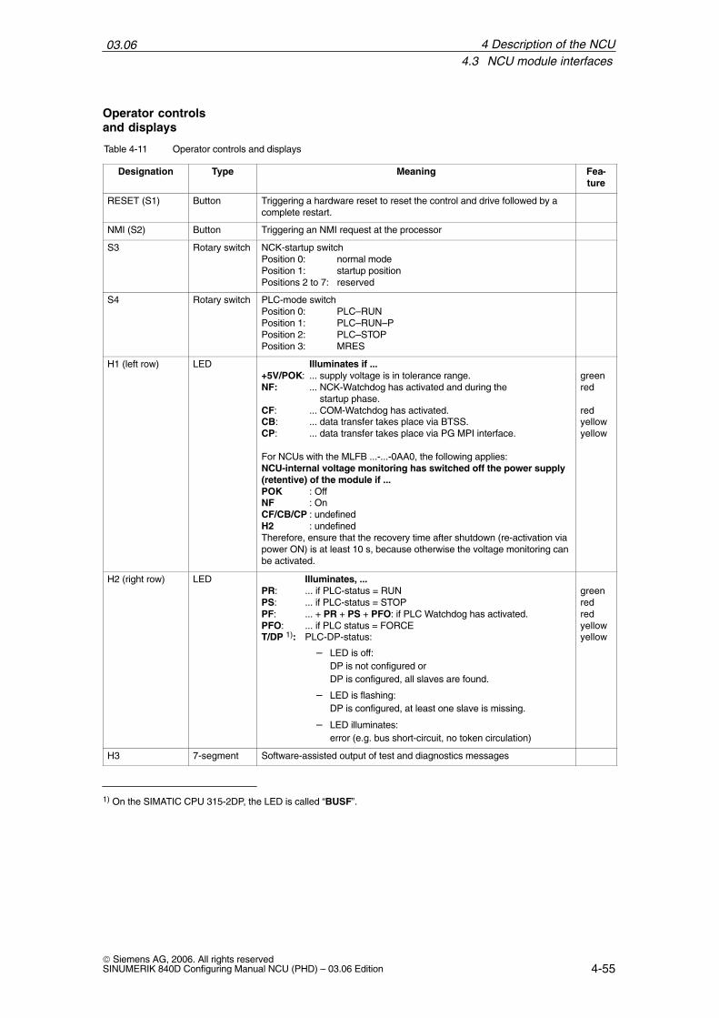
Table 4-11 Operator controls and displays
Designation Type Meaning Fea-ture
RESET (S1) Button Triggering a hardware reset to reset the control and drive followed by acomplete restart.
NMI (S2) Button Triggering an NMI request at the processor
S3 Rotary switch NCK-startup switchPosition 0: normal modePosition 1: startup positionPositions 2 to 7: reserved
S4 Rotary switch PLC-mode switchPosition 0: PLC–RUNPosition 1: PLC–RUN–PPosition 2: PLC–STOPPosition 3: MRES
H1 (left row) LED Illuminates if ... +5V/POK: ... supply voltage is in tolerance range.NF: ... NCK-Watchdog has activated and during the startup phase.CF: ... COM-Watchdog has activated.CB: ... data transfer takes place via BTSS.CP: ... data transfer takes place via PG MPI interface.
For NCUs with the MLFB ...-...-0AA0, the following applies:NCU-internal voltage monitoring has switched off the power supply(retentive) of the module if ...POK : OffNF : OnCF/CB/CP : undefinedH2 : undefinedTherefore, ensure that the recovery time after shutdown (re-activation viapower ON) is at least 10 s, because otherwise the voltage monitoring canbe activated.
greenred
redyellowyellow
H2 (right row) LED Illuminates, ...PR: ... if PLC-status = RUNPS: ... if PLC-status = STOPPF: ... + PR + PS + PFO: if PLC Watchdog has activated.PFO: ... if PLC status = FORCET/DP 1): PLC-DP-status:
– LED is off:DP is not configured orDP is configured, all slaves are found.
– LED is flashing:DP is configured, at least one slave is missing.
– LED illuminates:error (e.g. bus short-circuit, no token circulation)
greenredredyellowyellow
H3 7-segment Software-assisted output of test and diagnostics messages
1) On the SIMATIC CPU 315-2DP, the LED is called “BUSF”.
Operator controlsand displays
4 Description of the NCU
03.064.4 Cable distributor (distributor box)
4-56© Siemens AG, 2006. All rights reserved
SINUMERIK 840D Configuring Manual NCU (PHD) – 03.06 Edition
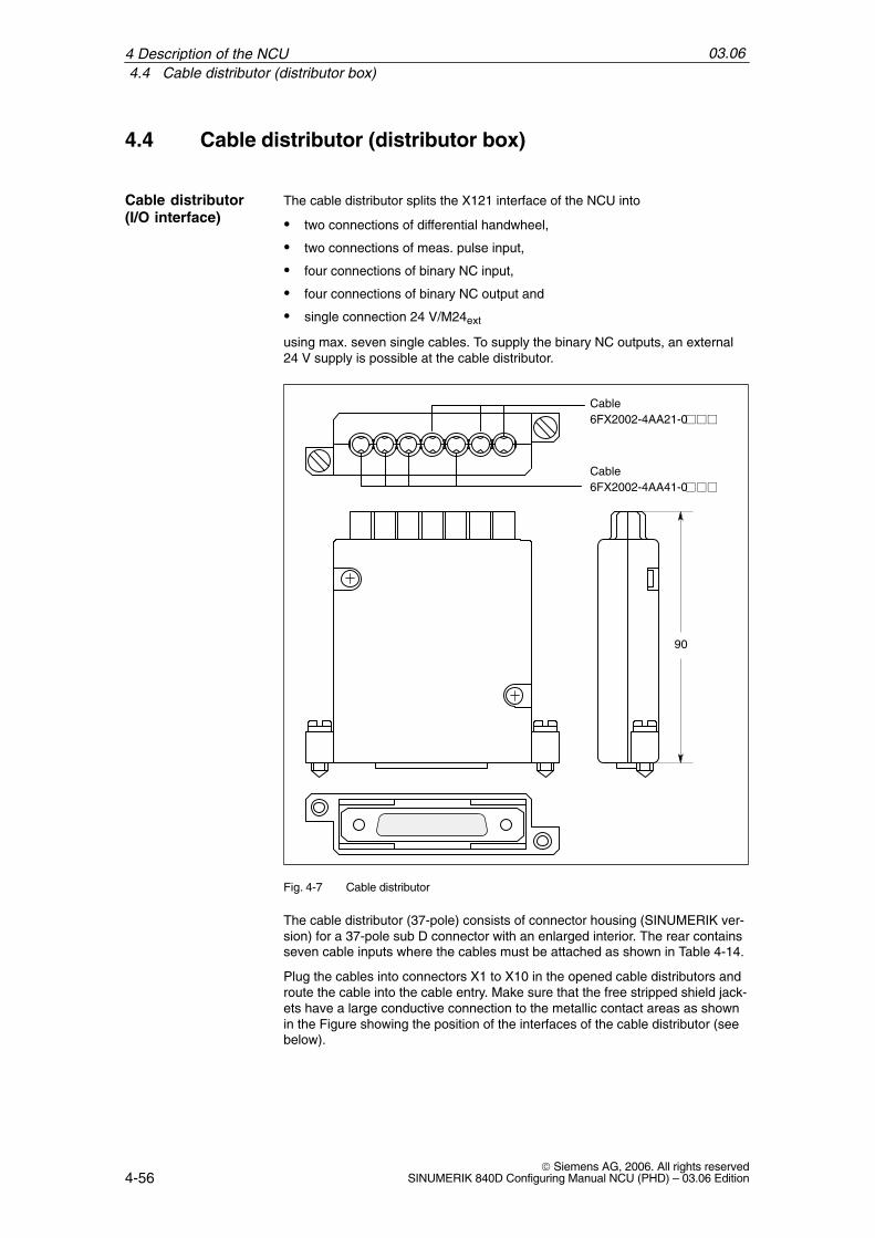
4.4 Cable distributor (distributor box)
The cable distributor splits the X121 interface of the NCU into
two connections of differential handwheel,
two connections of meas. pulse input,
four connections of binary NC input,
four connections of binary NC output and
single connection 24 V/M24ext
using max. seven single cables. To supply the binary NC outputs, an external24 V supply is possible at the cable distributor.
Cable6FX2002-4AA21-0
Cable6FX2002-4AA41-0
90
Fig. 4-7 Cable distributor
The cable distributor (37-pole) consists of connector housing (SINUMERIK ver-sion) for a 37-pole sub D connector with an enlarged interior. The rear containsseven cable inputs where the cables must be attached as shown in Table 4-14.
Plug the cables into connectors X1 to X10 in the opened cable distributors androute the cable into the cable entry. Make sure that the free stripped shield jack-ets have a large conductive connection to the metallic contact areas as shownin the Figure showing the position of the interfaces of the cable distributor (seebelow).
Cable distributor(I/O interface)
4 Description of the NCU

03.064.4 Cable distributor (distributor box)
4-57© Siemens AG, 2006. All rights reservedSINUMERIK 840D Configuring Manual NCU (PHD) – 03.06 Edition
Insert the upper terminal bar in such a way that its “teeth” are facing the “teeth”of the lower terminal bar and then secure the upper housing section.
This will reliably press the cable shields between the contact areas of the con-tact springs and contact them. Securing to the front panel of the NCU routes theshield potential via the contact springs of the cable distributor.
Status table for switches S1...S5 (Order No. 6FX 2006-1BA00)
The DIP FIX switches in the cable distributor must be set as follows:
Table 4-12 Setting the DIP-FIX switches in the cable distributor (S1...S5)
Switch S1 S2 S3 S4 S5
Open x x x x x
Closed
Status table for switches S1...S6 (Order No. 6FX 2006-1BA01)
The DIP FIX switches in the cable distributor must be set as follows:
Table 4-13 Setting the DIP-FIX switches in the cable distributor (S1...S6)
Switch S1 S2 S3 S4 S5 S6
Open x x x x
Closed x x
Open
Closed
X1 X2 X4 X5 X6 X7 X8 X9 X10X3
X11
Cable inlets
Terminal caps
Contact surfaces
Plug-in connectors X1...X10
S3S4S5 S1S2
Sub-D female connector
S6
1)
1) Not for Order No. 6FX 2006-1BA00
S1 to S6:
Fig. 4-8 Position of the interfaces of the cable distributor
Location of interfaces
4 Description of the NCU

03.064.4 Cable distributor (distributor box)
4-58© Siemens AG, 2006. All rights reserved
SINUMERIK 840D Configuring Manual NCU (PHD) – 03.06 Edition
Table 4-14 Connector assignments
Connector No. Cable No. Peripherals
X1 11 Hand wheel
X21
(top)1. Hand wheel
X32 2 Hand wheel
X42 2. Hand wheel
X5 3 2. Probe
X64 4 binary inputs
X74 4 binary inputs
X8 5 4 binary outputs
X9 6 Supply for 4 binary outputs
X107
(bottom)1. Probe
Pin 1
= coding pin
= no coding pin
Viewing direction:from behind toward the cabledistributor
Fig. 4-9 Position of the coding pins
Note
When assembling the cable distributor, make absolutely sure that the suppliedinsulating washer is installed correctly and the coding pins are installed.
Connectorassignments
Connector coding
4 Description of the NCU

03.064.4 Cable distributor (distributor box)
4-59© Siemens AG, 2006. All rights reservedSINUMERIK 840D Configuring Manual NCU (PHD) – 03.06 Edition
Connector designation: X1...X10Connector type: DU-BOX plug connectors
Table 4-15 Cable distributor pin assignment
Pin no.37-pin
connec-tor
Signalname
DU BOXconnector
No./pin
Cable No. Cable OrderNo.
6FX2002-4AACore color I/Os Terminal
9
10
–MEPUS 0
–MEPUC 0
X10/2X10/1X10/4X10/3
7 41–0
rdorbrbk
shield
1. Probe
1. Probe
Signal +24 V
Reference-signal 0 V
120221
M24EXTP24EXTM24EXTP24EXT
X9/2X9/1X9/4X9/3
6 41–0
rdorbrbk
shield
Supply of the 4 binary
outputs
Ground24 V
Ground24 V
322423
OUTPUT 1OUTPUT 3OUTPUT 0OUTPUT 2
X8/2X8/1X8/4X8/3
5 41–0
rdorbrbk
shield
4 binary outputs
2. Output4. Output1. Output3. Output
524625726827
INPUT 3MEXTINPUT 2MEXTINPUT 1MEXTINPUT 0MEXT
X7/2X7/1X7/4X7/3X6/2X6/1X6/4X6/3
4 21–0
rdorbrbkgnyeviobl
shield
4 binary inputs
4. input ground3. Input ground2. Input ground1. Input ground
28
29
–MEPUS 1
–MEPUC 1
X5/2X5/1X5/4X5/3
3 41–0
rdorbrbk
shield
2. Probe
2. Probe
Signal + 24 V
Referencesignal 0 V
1130123113321433
MPG1 XAMPG1 AMPG1 5VMPG1 0VMPG1 5VMPG1 0VMPG1 XBMPG1 B
X4/2X4/1X4/4X4/3X3/2X3/1X3/4X3/3
2 21–0
rdorbrbkgnyeviobl
shield
2. Handwheel
6FC9320-5DB
XAA
5 V0 V5 V0 VXBB
1534163517361837
MPG0 XAMPG0 AMPG0 5VMPG0 0VMPG0 5VMPG0 0VMPG0 XBMPG0 B
X2/2X2/1X2/4X2/3X1/2X1/1X1/4X1/3
1 21–0
rdorbrbkgnyeviobl
shield
1. Handwheel
6FC9320-5DB
XAA
5 V0 V5 V0 VXBB
Signal names
MPG 0/1 5V supply voltage handwheel 0/1. 5 V 1)
MPG 0/1 0V supply voltage handwheel 0/1.0 VMPG 0/1 A/XA differential handwheel input 0/1, A/XAMPG 0/1 B/XB differential handwheel input 0/1, B/XB
Pin assignment
4 Description of the NCU

03.064.5 Technical data
4-60© Siemens AG, 2006. All rights reserved
SINUMERIK 840D Configuring Manual NCU (PHD) – 03.06 Edition
MEPUS 0/1 measuring pulse signal 0/1 MEPUC 0/1 measuring pulse common (reference ground) 0/1INPUT [0...3] binary NC input 0...3 2)
MEXT external ground (reference ground for binary NC inputs)OUTPUT [0...3] binary NC output 0...3 3)
M24EXT external 24 V infeed (–) for binary NC outputsP24EXT external 24 V infeed (+) for binary NC outputs
1) Max. 500 mA per handwheel, i.e. a total of max. 1 A2) High level: rated value 24 V, limits 15 ..30 V / 2 mA...15 mA
Low level: rated vale 0 V or open, limits –3...5 V3) The binary outputs are short-circuit proof.
Max. switching current per output: 500 mA (coincidence factor 100%).For an inductive load, an external protective circuit is required for unloading
the inductivity
4.5 Technical data
Table 4-16 General technical data
Security
Protection class I (protective conductor) as per EN 61800–5–1
Degree of protection per EN 60529
IP20 (with NCU box)or IPXXB
IP00 (without NCU box)
Approvals CE / cULus
Degree of contamination 2
Cooling Open circuit ventilation
Mechanical ambient conditions
Transport (in transport packaging)
2M2 according to EN 60721–3–2
Bearings 1M2 according to EN 60721–3–1
4 Description of the NCU
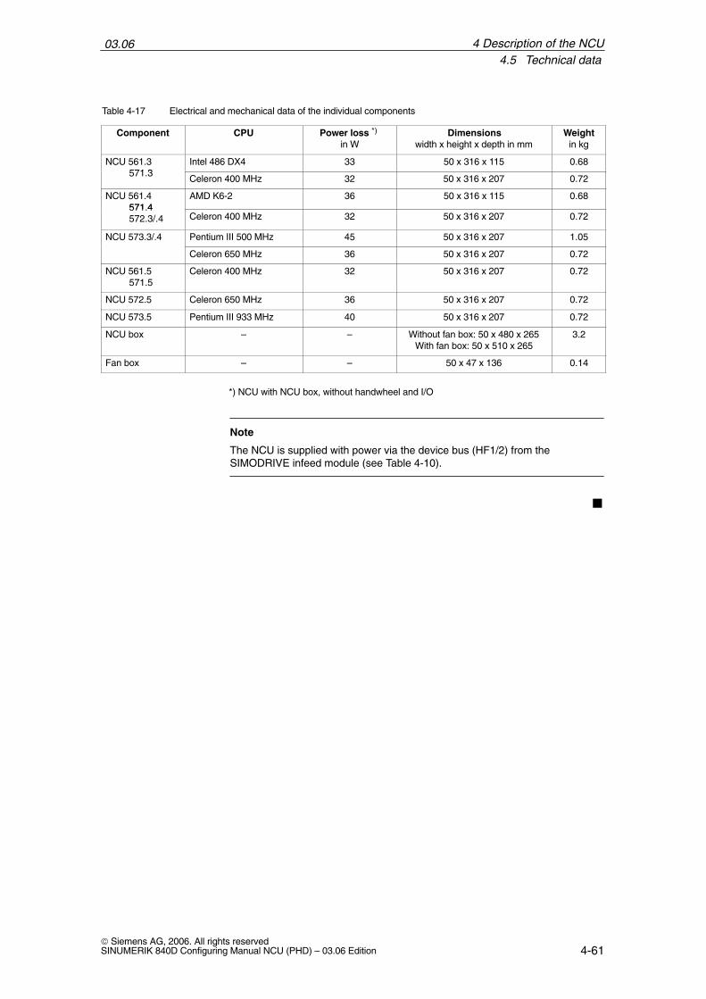
03.064.5 Technical data
4-61© Siemens AG, 2006. All rights reservedSINUMERIK 840D Configuring Manual NCU (PHD) – 03.06 Edition
Table 4-17 Electrical and mechanical data of the individual components
Component CPU Power loss *) in W
Dimensionswidth x height x depth in mm
Weightin kg
NCU 561.3571 3
Intel 486 DX4 33 50 x 316 x 115 0.68571.3
Celeron 400 MHz 32 50 x 316 x 207 0.72
NCU 561.4571 4
AMD K6-2 36 50 x 316 x 115 0.68571.4572.3/.4 Celeron 400 MHz 32 50 x 316 x 207 0.72
NCU 573.3/.4 Pentium III 500 MHz 45 50 x 316 x 207 1.05
Celeron 650 MHz 36 50 x 316 x 207 0.72
NCU 561.5571.5
Celeron 400 MHz 32 50 x 316 x 207 0.72
NCU 572.5 Celeron 650 MHz 36 50 x 316 x 207 0.72
NCU 573.5 Pentium III 933 MHz 40 50 x 316 x 207 0.72
NCU box – – Without fan box: 50 x 480 x 265With fan box: 50 x 510 x 265
3.2
Fan box – – 50 x 47 x 136 0.14
*) NCU with NCU box, without handwheel and I/O
Note
The NCU is supplied with power via the device bus (HF1/2) from theSIMODRIVE infeed module (see Table 4-10).
4 Description of the NCU

03.064.5 Technical data
4-62© Siemens AG, 2006. All rights reserved
SINUMERIK 840D Configuring Manual NCU (PHD) – 03.06 Edition
4 Description of the NCU
Notes

5-63© Siemens AG, 2006. All rights reservedSINUMERIK 840D Configuring Manual NCU (PHD) – 03.06 Edition
I/O Modules
5.1 Single I/O module
The single I/O module has 64 inputs and 32 short-circuit-proof outputs (iso-lated). Each output can be loaded with 0.5 A. The coincidence factor is 75%.
Up to three single I/O modules can be connected to the SINUMERIK 840D;combinations with SIMATIC S7-300 lines are possible.
The single I/O module (connector X3 IN) is connected to the SINUMERIK 840D(connector X111). The max. cable length is 10 m. Two cable variants are avail-able for the connection from one single I/O module to the next:
For single mounting: 6ES7368-30-0AA0
For single-tier configuration with several single I/O modules: 6FC5411-0AA80-0AA0, length 150 mm
840D
X111
ÏÏÏÏÏÏÏÏÏÏÏÏÏÏÏÏÏÏÏÏÏÏÏÏ
ÏÏÏÏÏÏÏÏÏÏÏÏÏÏÏÏÏÏÏÏÏÏÏÏ
ÏÏÏÏÏÏÏÏÏÏÏÏÏÏÏÏÏÏÏÏÏÏÏÏ
EFP EFP EFP
X3 X3 X3
ÏÏÏÏÏÏÏÏÏÏÏÏÏÏÏÏÏÏÏÏ
IM 361 or second single I/O module
X404
32 I
X405
32 I
X402
32 O
Terminal strip converter
Terminal strip converter
Terminal strip converter
6ES7368-30-0AA06FC5411-0AA80-0AA0, length 150 mm
6ES7368-30-0AA0
Ribbon cable
Ribbon cable
Ribbon cable
X3 IN
X3 OUT
SINUMERIK 840D 6ES7368-30-0AA0
EFP
Connecting cable shielded for single-tier configuration only6FC5411-0AA80-0AA0, length 150 mm
OUTIN OUTIN OUTIN
Fig. 5-1 Overview of connections, single I/O modules on the SINUMERIK 840D
Short description
Connection to 840D
5

03.065.1 Single I/O module
5-64© Siemens AG, 2006. All rights reserved
SINUMERIK 840D Configuring Manual NCU (PHD) – 03.06 Edition
360
135
374
25
Cooling clearance 50 mm
Cooling clearance 50 mm 70
Space for frontconnector
25
P24LogicM24SHIELD
P24PowerM24SHIELD
Fig. 5-2 Dimension drawing of single I/O module
The single I/O module has an equipotential bonding terminal. To conduct inter-ference currents away, a low-resistance finely stranded bonding conductor tothe ground bus is required (see Subsection 2.1.3) with a cross-section of atleast 10 mm2. The connection must be as short as possible. When the PE andinterference conductors are in common, the PE conductor rules in EN61800–5–1 must be followed.
EMC measures
5 I/O Modules

03.065.1 Single I/O module
5-65© Siemens AG, 2006. All rights reservedSINUMERIK 840D Configuring Manual NCU (PHD) – 03.06 Edition
Table 5-1 Technical data of the single I/O module
Power supply for LOGIC (X1) and POWER (X5)
– Nominal value– Perm. range– Ripple– Polarity reversal protection– Fuse-protection
Current consumption – LOGIC– POWER
Power loss – LOGIC– POWER
DC 24 V18.5 ... 30.2 V3.6 V ssyesLOGIC: 1 A/250 VPOWER: notype: 0.3 A , max. 1 Amax. 12 Atype: 7.2 W, max. 30.2 Wmax: 362 W
InputsNumber of inputsSignal level for signal “0”Signal level for signal “1”IsolationInput current 1-signal
64 digital inputs –3 V to + 5 V+ 15 V to +30 Vyes (optocoupler)2–15 mA type: 6 mAInput current 1-signal
Input current 0-signalDelay time TPHLDelay time TPLHNoise immunity (DIN 57847) Cable length terminal block
2–15 mA, type: 6 mA –9 mA to 1 mA 0.5 to 3 ms0.5 to 3 ms2 kVmax. 3 m
OutputsNumber of outputsSignal level for signal “0”Signal level for signal “1”IsolationShort-circuit-proofMax. output current
Switching frequency
Noise immunity (DIN 57847)Cable length terminal block
32 digital outputsopenUPower – 0.5 Vyes (optocoupler)yesresistive: 0.6 Ainductive: 0.6 Alamp: 6 Wohmic load: 100 Hzinductive load: 2 Hzlamp load: 11 Hz2 kVmax. 3 m
Overtemperature protection block-specific shutdown
Coincidence factorTotal of all nominal currents within each group of 0.5 A
75%
Degree of protection IP20 or IPXXB
Weight 1.7 kg
Technical data
5 I/O Modules
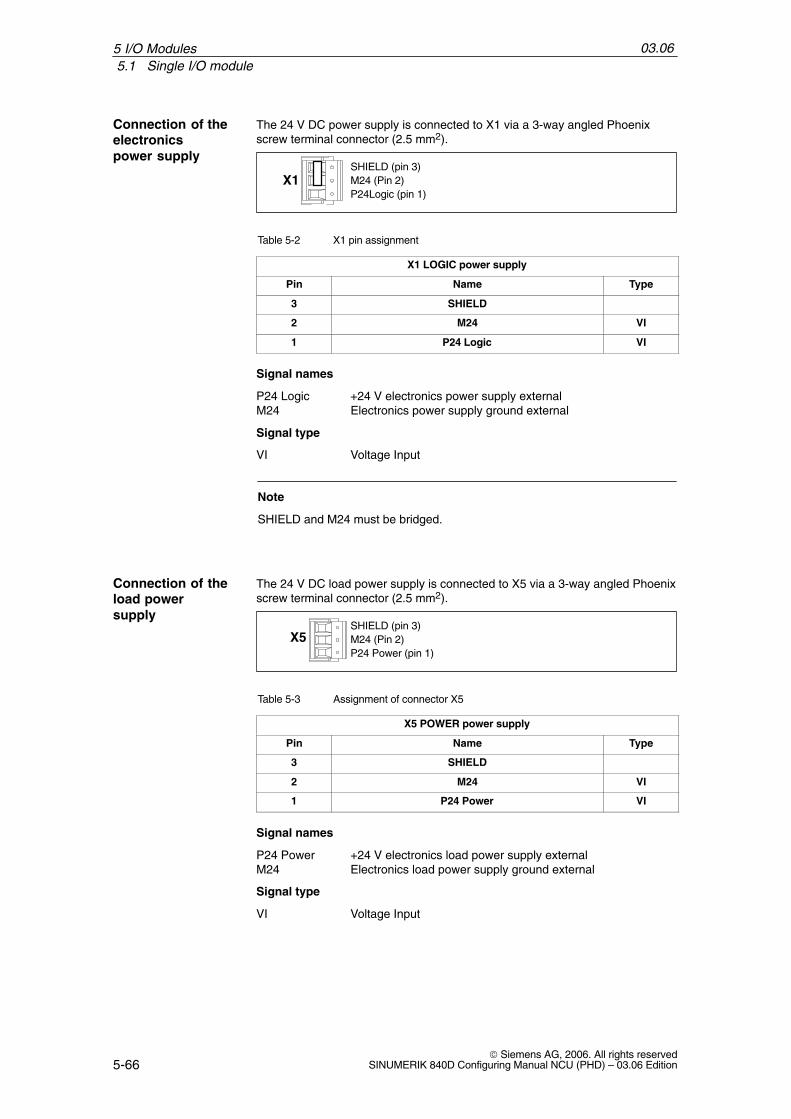
03.065.1 Single I/O module
5-66© Siemens AG, 2006. All rights reserved
SINUMERIK 840D Configuring Manual NCU (PHD) – 03.06 Edition
The 24 V DC power supply is connected to X1 via a 3-way angled Phoenixscrew terminal connector (2.5 mm2).
P24Logic (pin 1)M24 (Pin 2)SHIELD (pin 3)
X1
Table 5-2 X1 pin assignment
X1 LOGIC power supply
Pin Name Type
3 SHIELD
2 M24 VI
1 P24 Logic VI
Signal names
P24 Logic +24 V electronics power supply externalM24 Electronics power supply ground external
Signal type
VI Voltage Input
Note
SHIELD and M24 must be bridged.
The 24 V DC load power supply is connected to X5 via a 3-way angled Phoenixscrew terminal connector (2.5 mm2).
P24 Power (pin 1)M24 (Pin 2)SHIELD (pin 3)
X5
Table 5-3 Assignment of connector X5
X5 POWER power supply
Pin Name Type
3 SHIELD
2 M24 VI
1 P24 Power VI
Signal names
P24 Power +24 V electronics load power supply externalM24 Electronics load power supply ground external
Signal type
VI Voltage Input
Connection of the electronics power supply
Connection of theload power supply
5 I/O Modules
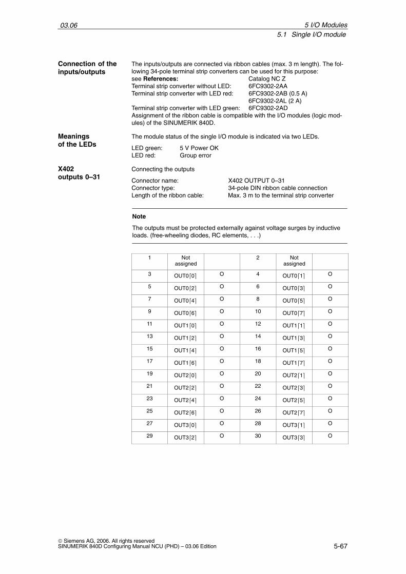
03.065.1 Single I/O module
5-67© Siemens AG, 2006. All rights reservedSINUMERIK 840D Configuring Manual NCU (PHD) – 03.06 Edition
The inputs/outputs are connected via ribbon cables (max. 3 m length). The fol-lowing 34-pole terminal strip converters can be used for this purpose:see References: Catalog NC ZTerminal strip converter without LED: 6FC9302-2AATerminal strip converter with LED red: 6FC9302-2AB (0.5 A)
6FC9302-2AL (2 A)Terminal strip converter with LED green: 6FC9302-2ADAssignment of the ribbon cable is compatible with the I/O modules (logic mod-ules) of the SINUMERIK 840D.
The module status of the single I/O module is indicated via two LEDs.
LED green: 5 V Power OKLED red: Group error
Connecting the outputs
Connector name: X402 OUTPUT 0–31Connector type: 34-pole DIN ribbon cable connectionLength of the ribbon cable: Max. 3 m to the terminal strip converter
Note
The outputs must be protected externally against voltage surges by inductiveloads. (free-wheeling diodes, RC elements, . . .)
1 Notassigned
2 Notassigned
3 OUT00 O 4 OUT01 O
5 OUT02 O 6 OUT03 O
7 OUT04 O 8 OUT05 O
9 OUT06 O 10 OUT07 O
11 OUT10 O 12 OUT11 O
13 OUT12 O 14 OUT13 O
15 OUT14 O 16 OUT15 O
17 OUT16 O 18 OUT17 O
19 OUT20 O 20 OUT21 O
21 OUT22 O 22 OUT23 O
23 OUT24 O 24 OUT25 O
25 OUT26 O 26 OUT27 O
27 OUT30 O 28 OUT31 O
29 OUT32 O 30 OUT33 O
Connection of the inputs/outputs
Meanings of the LEDs
X402outputs 0–31
5 I/O Modules
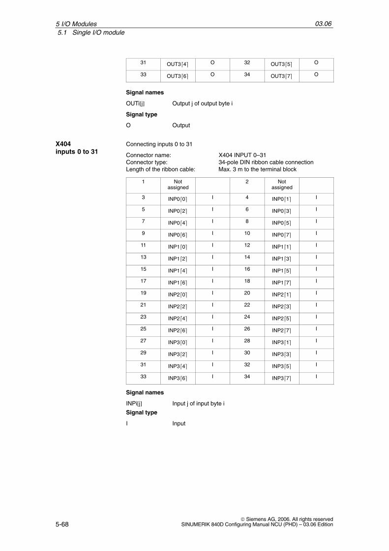
03.065.1 Single I/O module
5-68© Siemens AG, 2006. All rights reserved
SINUMERIK 840D Configuring Manual NCU (PHD) – 03.06 Edition
31 OUT34 O 32 OUT35 O
33 OUT36 O 34 OUT37 O
Signal names
OUTi[j] Output j of output byte i
Signal type
O Output
Connecting inputs 0 to 31
Connector name: X404 INPUT 0–31Connector type: 34-pole DIN ribbon cable connection Length of the ribbon cable: Max. 3 m to the terminal block
1 Notassigned
2 Notassigned
3 INP00 I 4 INP01 I
5 INP02 I 6 INP03 I
7 INP04 I 8 INP05 I
9 INP06 I 10 INP07 I
11 INP10 I 12 INP11 I
13 INP12 I 14 INP13 I
15 INP14 I 16 INP15 I
17 INP16 I 18 INP17 I
19 INP20 I 20 INP21 I
21 INP22 I 22 INP23 I
23 INP24 I 24 INP25 I
25 INP26 I 26 INP27 I
27 INP30 I 28 INP31 I
29 INP32 I 30 INP33 I
31 INP34 I 32 INP35 I
33 INP36 I 34 INP37 I
Signal names
INPi[j] Input j of input byte i
Signal type
I Input
X404inputs 0 to 31
5 I/O Modules

03.065.1 Single I/O module
5-69© Siemens AG, 2006. All rights reservedSINUMERIK 840D Configuring Manual NCU (PHD) – 03.06 Edition
Connecting inputs 32 to 63
Connector name: X405 INPUT 32–63Connector type: 34-pole DIN ribbon cable connection Length of the ribbon cable: Max. 3 m to the terminal block
1 Notassigned
2 Notassigned
3 INP40 I 4 INP41 I
5 INP42 I 6 INP43 I
7 INP44 I 8 INP45 I
9 INP46 I 10 INP47 I
11 INP50 I 12 INP51 I
13 INP52 I 14 INP53 I
15 INP54 I 16 INP55 I
17 INP56 I 18 INP57 I
19 INP60 I 20 INP61 I
21 INP62 I 22 INP63 I
23 INP64 I 24 INP65 I
25 INP66 I 26 INP67 I
27 INP70 I 28 INP71 I
29 INP72 I 30 INP73 I
31 INP74 I 32 INP75 I
33 INP76 I 34 INP77 I
Signal names
INPi[j] Input j of input byte i
Signal type
I Input
From the PLC’s viewpoint, the 840D single I/O is equivalent to a S7-300 I/Ochain with the following configuration:
P-bus interface IM-R
2 x 32-bit input module
1 x 32-bit output module
X405inputs 32 to 63
Address space
5 I/O Modules
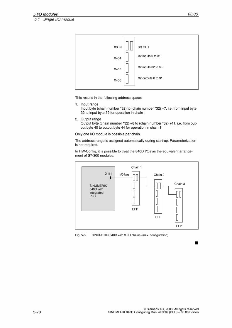
03.065.1 Single I/O module
5-70© Siemens AG, 2006. All rights reserved
SINUMERIK 840D Configuring Manual NCU (PHD) – 03.06 Edition
X404
X405
X406
X3 IN X3 OUT
32 inputs 0 to 31
32 inputs 32 to 63
32 outputs 0 to 31
This results in the following address space:
1. Input rangeInput byte (chain number *32) to (chain number *32) +7, i.e. from input byte32 to input byte 39 for operation in chain 1
2. Output rangeOutput byte (chain number *32) +8 to (chain number *32) +11, i.e. from out-put byte 40 to output byte 44 for operation in chain 1
Only one I/O module is possible per chain.
The address range is assigned automatically during start-up. Parameterizationis not required.
In HW-Config, it is possible to treat the 840D I/Os as the equivalent arrange-ment of S7-300 modules.
SINUMERIK840D with integratedPLC
X111
Chain 1
Chain 3
Chain 2I/O bus
EFP
EFP
EFP
Fig. 5-3 SINUMERIK 840D with 3 I/O chains (max. configuration)
5 I/O Modules

6-71© Siemens AG, 2006. All rights reservedSINUMERIK 840D Configuring Manual NCU (PHD) – 03.06 Edition
Terminal Block
6.1 NCU terminal block 6FC5211-0AA00-0AA0
PEconductor connection
Shielding plate
1 2 3 4 5 6 7 8
DMP compact module slots
X9: Terminal external 24 V logic power supply3 2 1
24 V
X20: Interface with the drive bus X21: Interface with the next NCU terminal block
40 V
237
257
74,4
2.5 mm2
Status LED green : 5V OKStatus LED yellow : Internal fault terminal blockStatus LED red : External fault (drive bus interface)
100
Depth: 40 mm or 130 mm (with DMP compact module)
Fig. 6-1 Front view of NCU terminal block
In order to ensure optimum heat dissipation of the DMP compact module, theterminal block should be secured horizontally, so that the modules can be sus-pended vertically.
Mounting
6

03.066.1 NCU terminal block 6FC5211-0AA00-0AA0
6-72© Siemens AG, 2006. All rights reserved
SINUMERIK 840D Configuring Manual NCU (PHD) – 03.06 Edition
The terminal block is connected to connector X20 on the drive bus of the lastdrive module via round cables. These cables are available in different lengths.(cable lengths 1, 2, 5, and 10 m). Up to 2 terminal blocks can be operated (inaccordance with the available NCK addresses for rapid analog and digital I/Os).The round cables are also used in conjunction with individual terminal blocks.
!Important
Please make sure that the total length of the cable connections does notexceed 10 m.
SIMODRIVE
NCU MSD FD
SIEMENS
Up to 2 NCU terminalblocks can be connected
Round cable
I/R
Terminationconnector
Drive busmax. length 10 m
Device bus
Connection PROFIBUS DP terminal block
Fig. 6-2 Connection of terminal block to 840D
The termination connector must be plugged into slot X21 on the last NCU termi-nal block.
When the PE and interference conductors are in common, the PE conductorrules in EN 61800–5–1 must be followed. PE conductor connection, seeFig. 6-1.
Connection to thedrive bus
Terminator
Protectiveconductor
6 Terminal Block
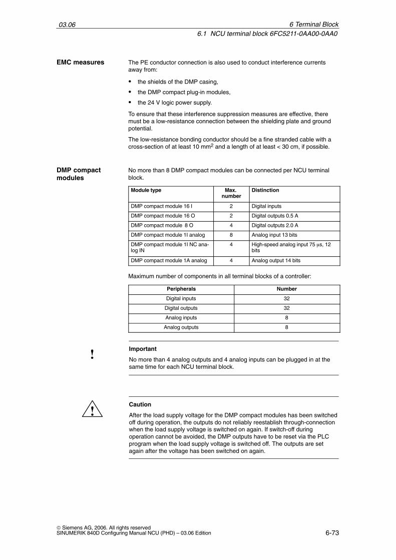
03.066.1 NCU terminal block 6FC5211-0AA00-0AA0
6-73© Siemens AG, 2006. All rights reservedSINUMERIK 840D Configuring Manual NCU (PHD) – 03.06 Edition
The PE conductor connection is also used to conduct interference currentsaway from:
the shields of the DMP casing,
the DMP compact plug-in modules,
the 24 V logic power supply.
To ensure that these interference suppression measures are effective, there must be a low-resistance connection between the shielding plate and groundpotential.
The low-resistance bonding conductor should be a fine stranded cable with across-section of at least 10 mm2 and a length of at least < 30 cm, if possible.
No more than 8 DMP compact modules can be connected per NCU terminalblock.
Module type Max. number
Distinction
DMP compact module 16 I 2 Digital inputs
DMP compact module 16 O 2 Digital outputs 0.5 A
DMP compact module 8 O 4 Digital outputs 2.0 A
DMP compact module 1I analog 8 Analog input 13 bits
DMP compact module 1I NC ana-log IN
4 High-speed analog input 75 s, 12bits
DMP compact module 1A analog 4 Analog output 14 bits
Maximum number of components in all terminal blocks of a controller:
Peripherals Number
Digital inputs 32
Digital outputs 32
Analog inputs 8
Analog outputs 8
!Important
No more than 4 analog outputs and 4 analog inputs can be plugged in at thesame time for each NCU terminal block.
!Caution
After the load supply voltage for the DMP compact modules has been switchedoff during operation, the outputs do not reliably reestablish through-connectionwhen the load supply voltage is switched on again. If switch-off duringoperation cannot be avoided, the DMP outputs have to be reset via the PLCprogram when the load supply voltage is switched off. The outputs are setagain after the voltage has been switched on again.
EMC measures
DMP compactmodules
6 Terminal Block

03.066.1 NCU terminal block 6FC5211-0AA00-0AA0
6-74© Siemens AG, 2006. All rights reserved
SINUMERIK 840D Configuring Manual NCU (PHD) – 03.06 Edition
+5 V monitoring
Temperature monitoring 60° C3°C
Configuration monitoring
Sign-of-life monitoring (watchdog) of the microcontroller
Sign-of-life monitoring of the NC
Error Acquisition Effect
Undervoltage (< 4.75 V)
Limit monitor Disabling of the NC outputs, LED(green) off
Ambient temperature Temperature sensor Status signal to NC, screen display
Sign of life NCU Cyclic signaling Disabling of the NC outputs, LED(red) on
Watchdog Timing Disabling of the NC outputs, LED(red) on
Hardware combination Hardware configura-tion
Disabling of the NC outputs LED(red, yellow) an, status signal to NC
The binary and analog outputs are switched to a safe state (0 V at the output)with the XOUTDS signal in the event of disturbances or faults in the NCU, themicrocontroller, and power failure.
DC 24 V (20.4 V DC to 28.8 V DC)Connector designation: X9Connector type: 4-pole terminal block, 2.5 mm2 Terminal
Table 6-1 X9 pin assignments
X9
Pin Name Type
1 P24 ext VI
2 P24 ext VI
3 M24 ext VI
4 M24 ext VI
Note
Pins 1 and 2 or 3 and 4 are bridged in a group on the module.
Signal names
P24 ext +24 V power supply externalM24 ext Power supply ground external
Signal type
VI Voltage Input
Monitoring
Power supply
6 Terminal Block

03.066.1 NCU terminal block 6FC5211-0AA00-0AA0
6-75© Siemens AG, 2006. All rights reservedSINUMERIK 840D Configuring Manual NCU (PHD) – 03.06 Edition
X Drive bus interface Connector name: X20 (IN) X21 (OUT)Connector type: 36-pole micro ribbonSpecial features: Non-isolated, no protective separationCaution: Max. length of the drive bus is 10 m
Module connectorConnector name: X11 ... X18 (slots 1 ... 8)Connector type: 30-pole male connector ELCO Microleaf
Table 6-2 Technical data of the NCU terminal block
Mechanical data
Dimensions Height Width Depth
100 mm 257 mm 40 mm
Weight Approx. 0.5 kg
Ambient conditions
Degree of protection IP20 or IPXXB
Power consumption (24 V)
During operation 150 – 500 mA
X20/X21
X11–X18
6 Terminal Block

03.066.1 NCU terminal block 6FC5211-0AA00-0AA0
6-76© Siemens AG, 2006. All rights reserved
SINUMERIK 840D Configuring Manual NCU (PHD) – 03.06 Edition
6 Terminal Block
Notes

7-77© Siemens AG, 2006. All rights reservedSINUMERIK 840D Configuring Manual NCU (PHD) – 03.06 Edition
DMP Compact Modules
The following dimensions must be observed when mounting:
Table 7-1 Dimensions of the DMP compact modules
Width 25 mm
Height 90 mm
115 mm with plugged in connecting plugs
130 mm with terminal block
Depth 108 mm
Degree ofprotection
IP20 or IPXXB
7.1 DMP compact module 16E 6FC5111-0CA01-0AA0
The DMP compact module 16E is an encapsulated module. It can be pluggedinto a slot of the (PROFIBUS DP or NCU) terminal block as a plug-in module.
P G 7 6 5
InputsIN 7 ... IN 0HIGH byte
X1
4 3 2 1 0
0 1 2 3 4 5 6 7 G P
Status LEDs
Fixing screw
Labeling strips
InputsIN 0 ... IN 7LOW byte
0 V
X3
X2
0..7
X3
X2
LOW byte
0..7
HIGH byte
1.5
0 V1.5
Fig. 7-1 Front view and side view of a DMP compact module 16E
Mounting
7
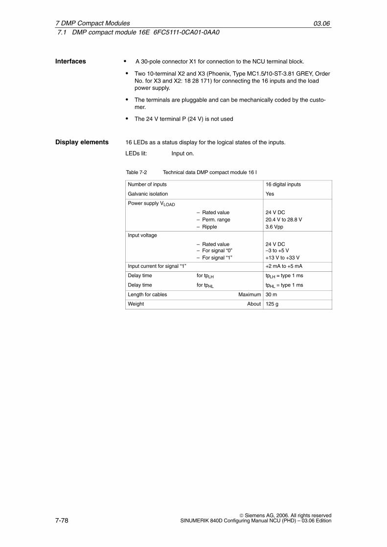
03.067.1 DMP compact module 16E 6FC5111-0CA01-0AA0
7-78© Siemens AG, 2006. All rights reserved
SINUMERIK 840D Configuring Manual NCU (PHD) – 03.06 Edition
A 30-pole connector X1 for connection to the NCU terminal block.
Two 10-terminal X2 and X3 (Phoenix, Type MC1.5/10-ST-3.81 GREY, OrderNo. for X3 and X2: 18 28 171) for connecting the 16 inputs and the loadpower supply.
The terminals are pluggable and can be mechanically coded by the custo-mer.
The 24 V terminal P (24 V) is not used
16 LEDs as a status display for the logical states of the inputs.
LEDs lit: Input on.
Table 7-2 Technical data DMP compact module 16 I
Number of inputs 16 digital inputs
Galvanic isolation Yes
Power supply VLOAD
– Rated value 24 V DC– Perm. range 20.4 V to 28.8 V– Ripple 3.6 Vpp
Input voltage
– Rated value– For signal “0”
24 V DC–3 to +5 V
– For signal “1” +13 V to +33 V
Input current for signal “1” +2 mA to +5 mA
Delay time for tpLH tpLH = type 1 ms
Delay time for tpHL tpHL = type 1 ms
Length for cables Maximum 30 m
Weight About 125 g
Interfaces
Display elements
7 DMP Compact Modules
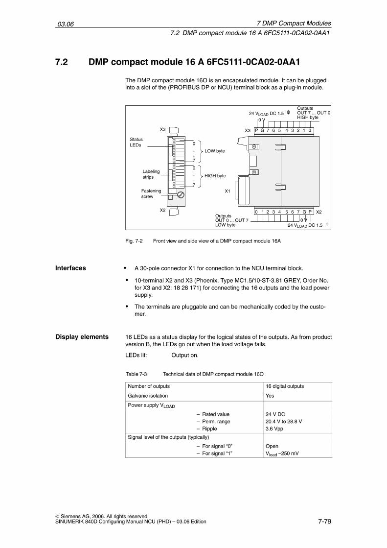
03.067.2 DMP compact module 16 A 6FC5111-0CA02-0AA1
7-79© Siemens AG, 2006. All rights reservedSINUMERIK 840D Configuring Manual NCU (PHD) – 03.06 Edition
7.2 DMP compact module 16 A 6FC5111-0CA02-0AA1
The DMP compact module 16O is an encapsulated module. It can be pluggedinto a slot of the (PROFIBUS DP or NCU) terminal block as a plug-in module.
P G 7 6 5
OutputsOUT 7 ... OUT 0HIGH byte
X1
4 3 2 1 0
0 1 2 3 4 5 6 7 G P
Status LEDs
Fastening screw
Labeling strips
OutputsOUT 0 ... OUT 7LOW byte
0 V
X3
X2
0..7
X3
X2
LOW byte
0..7
HIGH byte
24 VLOAD DC 1.5
0 V24 VLOAD DC 1.5
Fig. 7-2 Front view and side view of a DMP compact module 16A
A 30-pole connector X1 for connection to the NCU terminal block.
10-terminal X2 and X3 (Phoenix, Type MC1.5/10-ST-3.81 GREY, Order No.for X3 and X2: 18 28 171) for connecting the 16 outputs and the load powersupply.
The terminals are pluggable and can be mechanically coded by the custo-mer.
16 LEDs as a status display for the logical states of the outputs. As from productversion B, the LEDs go out when the load voltage fails.
LEDs lit: Output on.
Table 7-3 Technical data of DMP compact module 16O
Number of outputs 16 digital outputs
Galvanic isolation Yes
Power supply VLOAD
– Rated value 24 V DC– Perm. range 20.4 V to 28.8 V– Ripple 3.6 Vpp
Signal level of the outputs (typically)
– For signal “0” Open– For signal “1” Vload –250 mV
Interfaces
Display elements
7 DMP Compact Modules

03.067.2 DMP compact module 16 A 6FC5111-0CA02-0AA1
7-80© Siemens AG, 2006. All rights reserved
SINUMERIK 840D Configuring Manual NCU (PHD) – 03.06 Edition
Table 7-3 Technical data of DMP compact module 16O
Output load for signal “1” (rated value)
– Ohmic load 500 mA– Lamp load 5 W– Inductive load 500 mA
Short-circuit protection Yes
Power loss at 30 V max. 3.8 W
Operating frequency for
– Ohmic load 100 Hz– Lamps 11 Hz– Inductive load (for rated
load, higher values arepermissible for lowerloads)
2 Hz
Derated loading at 55 C (relative to the total of the ratedcurrents of all outputs)
50%
Delay time for tpLH tpLH = max. 0.5 ms
Delay time for tpHL tpHL = max. 0.5 ms
Length for cables Maximum 30 m
Weight About 160 g
!Important
As of version C, a new output driver is used for the DMP compact module 16A.The following behavior is to be observed:In the event of a fault triggered by overcurrent or short-circuit, the outputsautomatically reconnect after the fault has been rectified. (previously: aretentive shutdown until the output is energized again by the PLC userprogram).When an output is short-circuited, the three additional outputs of thecorresponding half byte can also be shutdown.In normal mode, with currents of < 0.7 A, no opposing effect occurs.
8 outputs each are powered by a power supply. For each group of 8 outputs(2 x outputs 0 ... 7), the total of the output currents must not be greater than 2 A.(This corresponds to a coincidence factor of 50% if each output is under fullload). All 16 outputs can be loaded simultaneously with 0.25 A for example.
!Important
If inductive loads are used, switching voltage peaks must be limited by externalfree-wheeling diodes or RC connections.
7 DMP Compact Modules
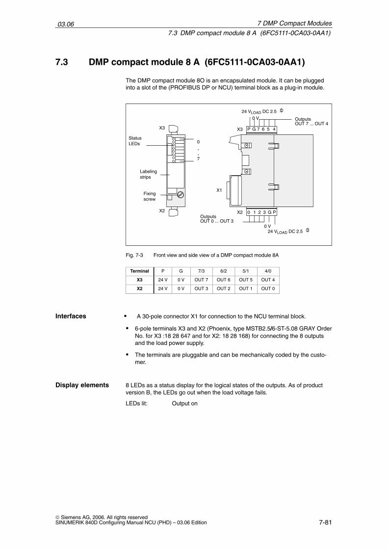
03.067.3 DMP compact module 8 A (6FC5111-0CA03-0AA1)
7-81© Siemens AG, 2006. All rights reservedSINUMERIK 840D Configuring Manual NCU (PHD) – 03.06 Edition
7.3 DMP compact module 8 A (6FC5111-0CA03-0AA1)
The DMP compact module 8O is an encapsulated module. It can be pluggedinto a slot of the (PROFIBUS DP or NCU) terminal block as a plug-in module.
X3 7 6 5
OutputsOUT 7 ... OUT 4
X1
4
Status LEDs
Fixing screw
Labeling strips
OutputsOUT 0 ... OUT 3
0 V
X2
0..7
X3
X2
24 VLOAD DC 2.5
210
0 V24 VLOAD DC 2.5
P G
PG3
Fig. 7-3 Front view and side view of a DMP compact module 8A
Terminal P G 7/3 6/2 5/1 4/0
X3 24 V 0 V OUT 7 OUT 6 OUT 5 OUT 4
X2 24 V 0 V OUT 3 OUT 2 OUT 1 OUT 0
A 30-pole connector X1 for connection to the NCU terminal block.
6-pole terminals X3 and X2 (Phoenix, type MSTB2.5/6-ST-5.08 GRAY OrderNo. for X3 :18 28 647 and for X2: 18 28 168) for connecting the 8 outputsand the load power supply.
The terminals are pluggable and can be mechanically coded by the custo-mer.
8 LEDs as a status display for the logical states of the outputs. As of productversion B, the LEDs go out when the load voltage fails.
LEDs lit: Output on
Interfaces
Display elements
7 DMP Compact Modules

03.067.3 DMP compact module 8 A (6FC5111-0CA03-0AA1)
7-82© Siemens AG, 2006. All rights reserved
SINUMERIK 840D Configuring Manual NCU (PHD) – 03.06 Edition
Table 7-4 Technical data of DMP compact module 8O
Number of outputs 8 digital outputs
Galvanic isolation Yes
Power supply VLOAD
– Rated value 24 V DC– Perm. range 20.4 V to 28.8 V– Ripple 3.6 Vpp
Signal level of the outputs (typically)
– For signal “0” Open– For signal “1” Vload –80 mV
Output load for signal “1” (rated value)
– Ohmic load 2000 mA– Lamp load 25 W– Inductive load 2000 mA
Short-circuit protection Yes
Power loss at 30 V max. 3.1 W
Operating frequency for
– Ohmic load 100 Hz– Lamps 11 Hz– Inductive load (for rated
load, higher values arepermissible for lowerloads)
2 Hz
Derated loading at 55 C (relative to the total of the ratedcurrents of all outputs)
50%
Delay time for tpLH tpLH = max. 0.5 ms
Delay time for tpHL tpHL = max. 0.5 ms
Length for cables Maximum 30 m
Weight About 145 g
4 outputs each are powered by a power supply. For each group of 4 outputs(outputs 0 to 3 and 4 to 7), the total of the output currents must not be greaterthan 4 A. (This corresponds to a coincidence factor of 50 % if each output isunder full load). All 8 outputs can be loaded simultaneously with 1 A for exam-ple.
!Important
If inductive loads are used, switching voltage peaks must be limited by externalfree-wheeling diodes or RC connections.
7 DMP Compact Modules

03.067.4 DMP compact module 1I analog 6FC5 111-0CA04-0AA0
7-83© Siemens AG, 2006. All rights reservedSINUMERIK 840D Configuring Manual NCU (PHD) – 03.06 Edition
7.4 DMP compact module 1I analog 6FC5 111-0CA04-0AA0
The DMP compact module 1I analog is an encapsulated module. It can beplugged into a slot of the (PROFIBUS DP or NCU) terminal block as a plug-inmodule. The conversion time is a max. of 60 ms in the rated range and a max.of 80 ms in the overshoot range.
M2M1P2P1
24 V DC
6, 1 Shield2 Curr. source for PT1003 Analog input In+4 Analog input In–5 Ground
X1
StatusLED
Fastening screw
Labeling strips
POWERSUPPLY
O.K.
ANALOG
IN
Connection terminalsX3
X2
0 V
13 2
1 2
S1S2
2,5
2.5
6 . . 1 Terminal:
Fig. 7-4 Front view and side view of a DMP compact module 1E analog
A 30-pole connector X1 for connection to the NCU terminal block.
4x terminal X3 (Phoenix, Type MSTB2.5/4-ST-5.08 GREY, Order No. for X3:18 48 407) for connecting the power supply for the analog part and 6x termi-nal X2 (Phoenix, Type MSTB2.5/6-ST-5.08 GREY, Order No. for X2: 17 87076) for connecting the analog input.
The terminals are pluggable and can be mechanically coded by the custo-mer.
1 LED as a status display for the power supply.
LED lit: Internal power supply OK
S1: Setting of the measurement range1–2 closed: +10 V1–3 closed: +500 mV
S2: Setting the line frequencyclosed: for 50 Hz systemsopen: for 60 Hz systems
Interfaces
Display elements
Jumpering
7 DMP Compact Modules
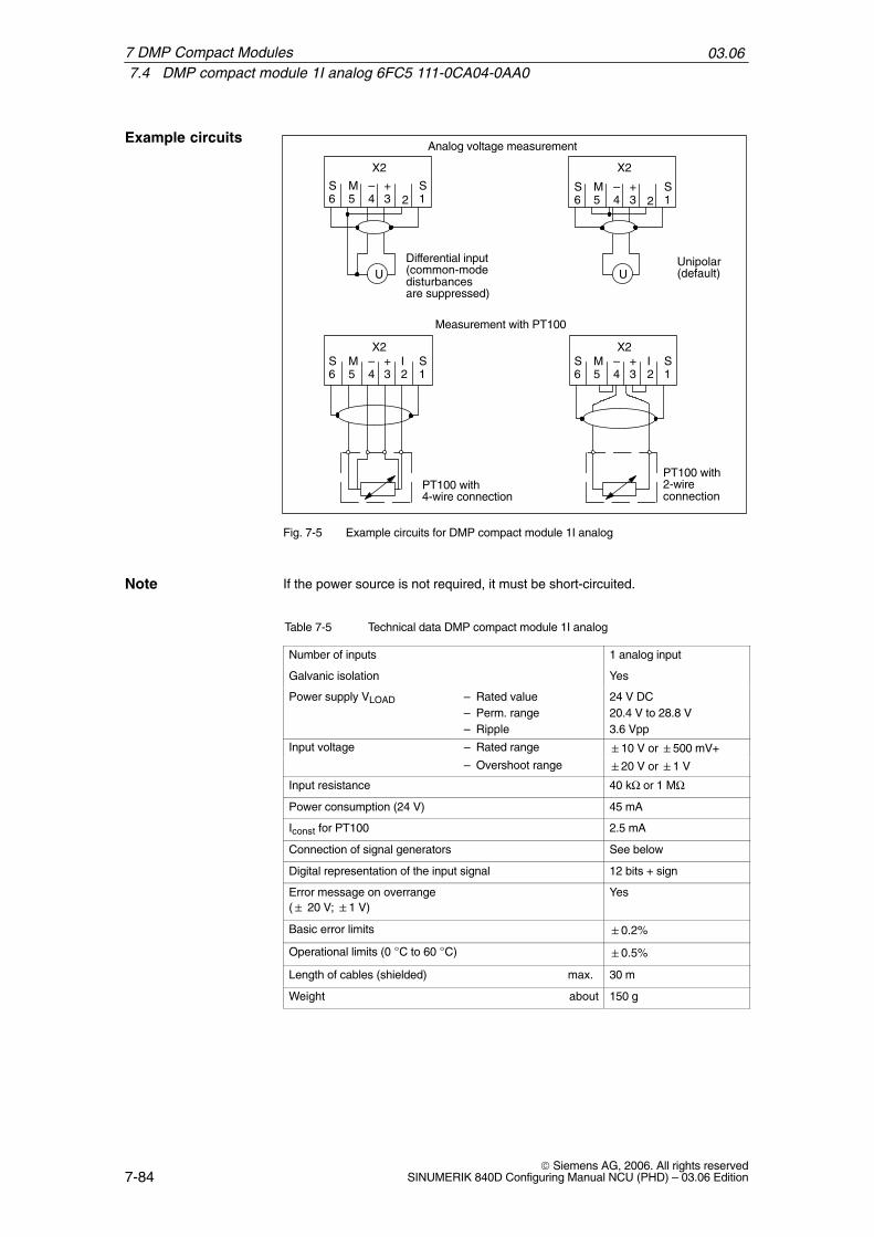
03.067.4 DMP compact module 1I analog 6FC5 111-0CA04-0AA0
7-84© Siemens AG, 2006. All rights reserved
SINUMERIK 840D Configuring Manual NCU (PHD) – 03.06 Edition
Analog voltage measurement
U U
Measurement with PT100
Differential input(common-modedisturbancesare suppressed)
Unipolar(default)
PT100 with4-wire connection
PT100 with2-wire connection
S6
M5
–4
+3 2
S1
X2
S6
M5
–4
+3 2
S1
X2
S6
M5
–4
+3
S1
X2S6
M5
–4
+3
I2
S1
X2I2
Fig. 7-5 Example circuits for DMP compact module 1I analog
If the power source is not required, it must be short-circuited.
Table 7-5 Technical data DMP compact module 1I analog
Number of inputs 1 analog input
Galvanic isolation Yes
Power supply VLOAD – Rated value 24 V DC– Perm. range 20.4 V to 28.8 V– Ripple 3.6 Vpp
Input voltage – Rated range 10 V or 500 mV+– Overshoot range 20 V or 1 V
Input resistance 40 kΩ or 1 MΩ
Power consumption (24 V) 45 mA
Iconst for PT100 2.5 mA
Connection of signal generators See below
Digital representation of the input signal 12 bits + sign
Error message on overrange ( 20 V; 1 V)
Yes
Basic error limits 0.2%
Operational limits (0 C to 60 C) 0.5%
Length of cables (shielded) max. 30 m
Weight about 150 g
Example circuits
Note
7 DMP Compact Modules

03.067.4 DMP compact module 1I analog 6FC5 111-0CA04-0AA0
7-85© Siemens AG, 2006. All rights reservedSINUMERIK 840D Configuring Manual NCU (PHD) – 03.06 Edition
The DMP compact module 1I analog is used to input and digitize an analogvoltage value. This voltage value is measured by an isolated differential input.
In conjunction with the installed constant current source (2.5 mA), it is possibleto connect PT100 resistance thermometers.
The conversion time depends on the level of the input voltage.Input voltage in the dimensioning range ––> conversion time < 60 ms input voltage in the overshoot range ––> conversion time < 80 ms The integration time is included in the conversion time, which determines thenoise suppression:S 2 closed––> Integration time 20 ms 50 Hz noise suppression. S 2 open ––> Integration time 16 2/3 ms 60 Hz noise suppression.
Table 7-6 Digital analog value representation for DMP compact module 1E analog
Input word IB m IB m+1 Analog input voltage
7 6 5 4 3 2 1 0 7 6 5 4 3 2 1 0 10V range 500 mV range
Significance VZ 211 210 29 28 27 26 25 24 23 22 21 20 0 0R PFrange
0 1 1 1 1 1 1 1 1 1 1 1 1 0 0 0 19.995 V 999.76 mV
: : : :
0 1 0 0 0 0 0 0 0 0 0 0 1 0 0 0 10.005 V 500.24 mV
0 1 0 0 0 0 0 0 0 0 0 0 0 0 0 0 10 V 500 mV
0 0 1 1 1 1 1 1 1 1 1 1 1 0 0 0 9.995 V 499.76 mV
: : : :
Digital value 0 0 0 0 0 0 0 0 0 0 0 0 1 0 0 0 0.005 V 0.24 mV
0 0 0 0 0 0 0 0 0 0 0 0 0 0 0 0 0 V 0 mV
1 1 1 1 1 1 1 1 1 1 1 1 1 0 0 0 –0.005 V –0.24 mV
: : : :
1 1 0 0 0 0 0 0 0 0 0 0 1 0 0 0 –9.995 V –499.76 mV
1 1 0 0 0 0 0 0 0 0 0 0 0 0 0 0 –10 V –500 mV
1 0 1 1 1 1 1 1 1 1 1 1 1 0 0 0 –10.005 V –500.24 mV
: : : :
1 0 0 0 0 0 0 0 0 0 0 0 1 0 0 0 –19.995 V – 999.76 mV
0 = Always 0
OR= Overflow bit, input voltage is greater than 20 V or 1 V (double inputrange)
PF = Power supply failure of the analog part
Conversion time
7 DMP Compact Modules

03.067.5 DMP compact module 1E NC analog
7-86© Siemens AG, 2006. All rights reserved
SINUMERIK 840D Configuring Manual NCU (PHD) – 03.06 Edition
7.5 DMP compact module 1E NC analog6FC5211-0AA10-0AA0
The DMP compact module 1E NC analog is an encapsulated high-speed ana-log input module with 75s access time. It can be plugged into a slot of the NCUterminal block as a plug-in module.The DMP compact module 1E NC analog serves for inputting and digitizing ananalog voltage value. This voltage value is measured by an isolated differentialinput.
M2M1P2P1
24 V DC
6, 1 Shield2 Ground3 Analog input In+4 Analog input In–5 Ground
X1
StatusLED
Fastening screw
Labeling strips
POWERSUPPLY
O.K.
ANALOG
IN
Connection terminalsX3
X2
0 V
13 2
1 2
2.5
2.5
6 . . 1 Terminal:
Fig. 7-6 Front view and side view of a DMP compact module 1E NC analog
A 30-pole connector X1 for connection to the NCU terminal block.
4x terminal X3 (Phoenix, Type MSTB2.5/4-ST-5.08 GREY, Order No. for X3:18 48 407) for connecting the power supply for the analog part and 6x termi-nal X2 (Phoenix, Type MSTB2.5/6-ST-5.08 GREY, Order No. for X2: 17 87076) for connecting the analog input.
The terminals are pluggable and can be mechanically coded by the custo-mer.
1 LED as a status display for the power supply. LED lit: internal power supply OK.
The converter result is available to the user as two’s complement. The resolu-tion is 4.88 mV for one bit. The duration for a converter cycle (from triggering ofconversion to the time at which the result can be read out) is max. 75 µs.
Interfaces
Display elements
Analog-valuerepresentation
7 DMP Compact Modules
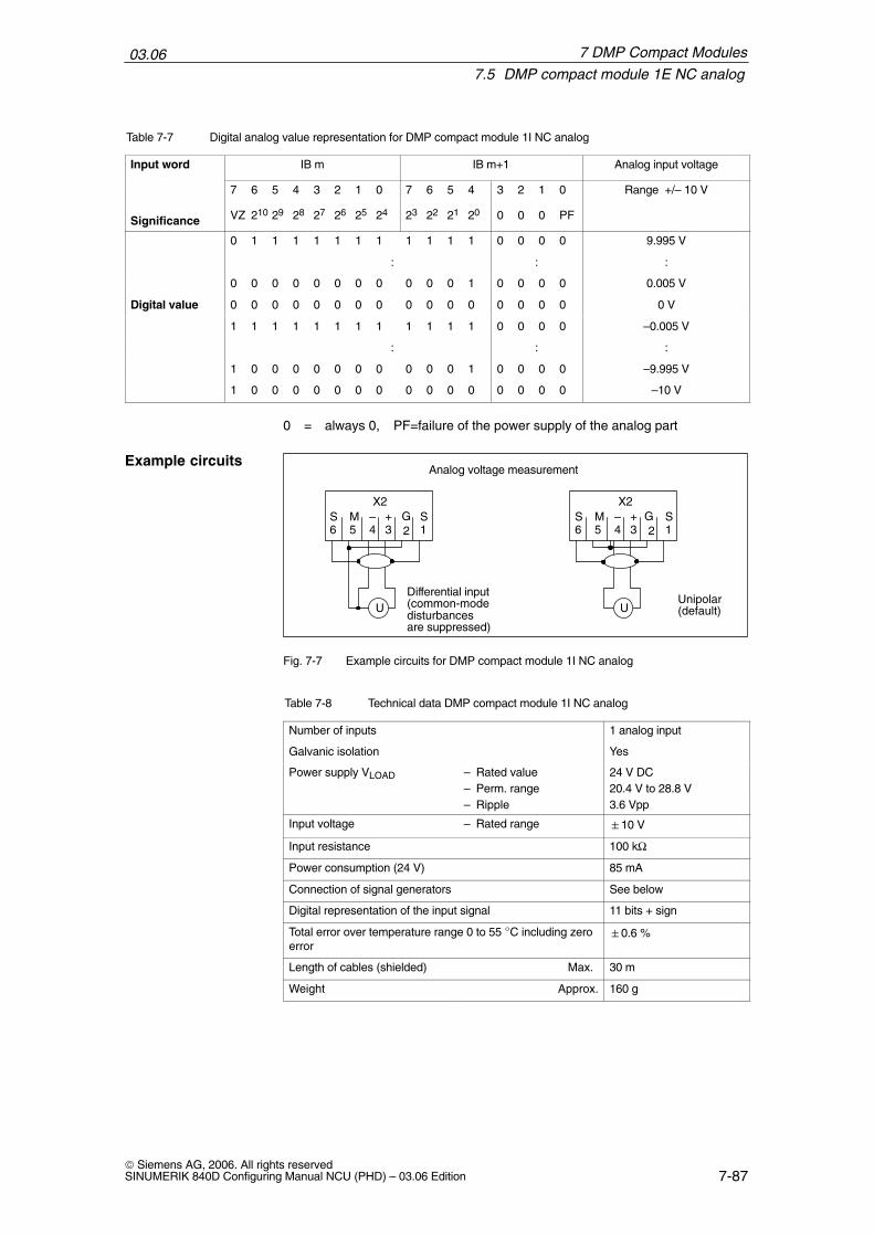
03.067.5 DMP compact module 1E NC analog
7-87© Siemens AG, 2006. All rights reservedSINUMERIK 840D Configuring Manual NCU (PHD) – 03.06 Edition
Table 7-7 Digital analog value representation for DMP compact module 1I NC analog
Input word IB m IB m+1 Analog input voltage
7 6 5 4 3 2 1 0 7 6 5 4 3 2 1 0 Range +/– 10 V
Significance VZ 210 29 28 27 26 25 24 23 22 21 20 0 0 0 PF
0 1 1 1 1 1 1 1 1 1 1 1 0 0 0 0 9.995 V
: : :
0 0 0 0 0 0 0 0 0 0 0 1 0 0 0 0 0.005 V
Digital value 0 0 0 0 0 0 0 0 0 0 0 0 0 0 0 0 0 V
1 1 1 1 1 1 1 1 1 1 1 1 0 0 0 0 –0.005 V
: : :
1 0 0 0 0 0 0 0 0 0 0 1 0 0 0 0 –9.995 V
1 0 0 0 0 0 0 0 0 0 0 0 0 0 0 0 –10 V
0 = always 0, PF=failure of the power supply of the analog part
Analog voltage measurement
U UDifferential input(common-modedisturbancesare suppressed)
Unipolar(default)
S6
M5
–4
+3 2
S1
X2S6
M5
–4
+3 2
S1
X2G G
Fig. 7-7 Example circuits for DMP compact module 1I NC analog
Table 7-8 Technical data DMP compact module 1I NC analog
Number of inputs 1 analog input
Galvanic isolation Yes
Power supply VLOAD – Rated value 24 V DC– Perm. range 20.4 V to 28.8 V– Ripple 3.6 Vpp
Input voltage – Rated range 10 V
Input resistance 100 kΩ
Power consumption (24 V) 85 mA
Connection of signal generators See below
Digital representation of the input signal 11 bits + sign
Total error over temperature range 0 to 55 C including zeroerror
0.6 %
Length of cables (shielded) Max. 30 m
Weight Approx. 160 g
Example circuits
7 DMP Compact Modules
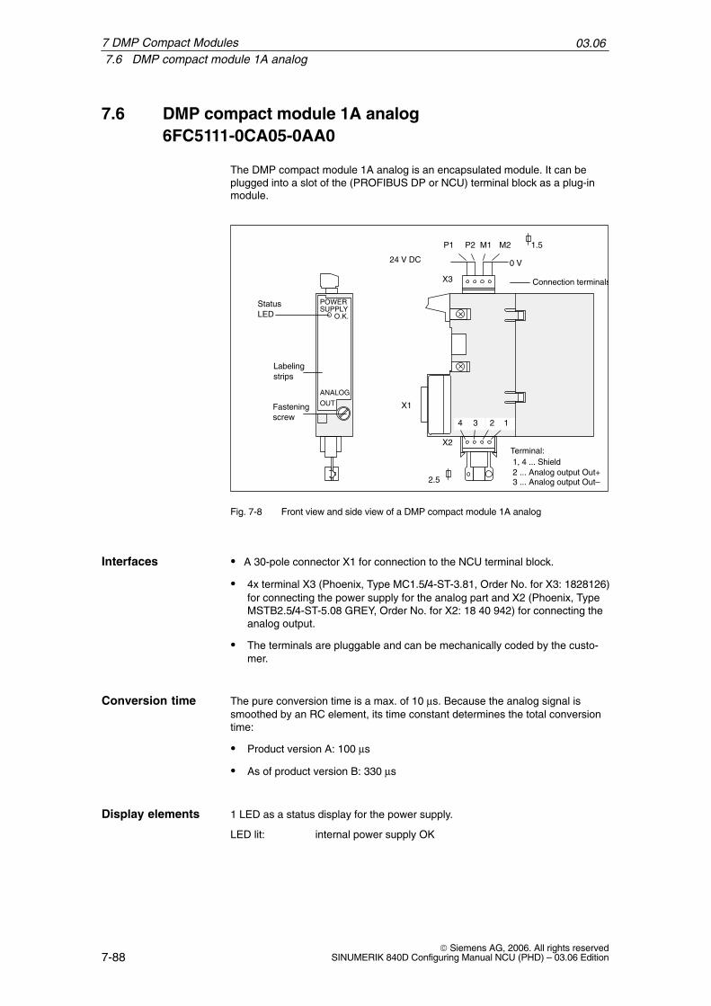
03.067.6 DMP compact module 1A analog
7-88© Siemens AG, 2006. All rights reserved
SINUMERIK 840D Configuring Manual NCU (PHD) – 03.06 Edition
7.6 DMP compact module 1A analog6FC5111-0CA05-0AA0
The DMP compact module 1A analog is an encapsulated module. It can beplugged into a slot of the (PROFIBUS DP or NCU) terminal block as a plug-inmodule.
24 V DC
1, 4 ... Shield2 ... Analog output Out+
X1
StatusLED
Fastening screw
Labeling strips
POWERSUPPLY
O.K.
ANALOG
OUT
Connection terminalsX3
X2
0 V
2.5
1.5
1234
P1 P2 M1 M2
Terminal:
3 ... Analog output Out–
Fig. 7-8 Front view and side view of a DMP compact module 1A analog
A 30-pole connector X1 for connection to the NCU terminal block.
4x terminal X3 (Phoenix, Type MC1.5/4-ST-3.81, Order No. for X3: 1828126)for connecting the power supply for the analog part and X2 (Phoenix, TypeMSTB2.5/4-ST-5.08 GREY, Order No. for X2: 18 40 942) for connecting theanalog output.
The terminals are pluggable and can be mechanically coded by the custo-mer.
The pure conversion time is a max. of 10 µs. Because the analog signal issmoothed by an RC element, its time constant determines the total conversiontime:
Product version A: 100 µs
As of product version B: 330 µs
1 LED as a status display for the power supply.
LED lit: internal power supply OK
Interfaces
Conversion time
Display elements
7 DMP Compact Modules

03.067.6 DMP compact module 1A analog
7-89© Siemens AG, 2006. All rights reservedSINUMERIK 840D Configuring Manual NCU (PHD) – 03.06 Edition
Table 7-9 Technical data DMP compact module 1A analog
Number of outputs 1 analog output
Galvanic isolation Yes
Power supply VLOAD
– Rated value 24 V DC– Perm. range 20.4 V to 28.8 V– Ripple 3.6 Vpp
Power consumption (24 V) 60 mA
Output voltage – Rated range 10 V DC
Output current 3 mA
Load resistance at voltage outputs Min. 3.3 kΩDigital representation of the input signal 13 bits + sign
Short-circuit protection Yes
Length of cables (shielded) Max. 30 m
Weight About 140 g
Table 7-10 Digital analog value representation DMP compact module 1A analog
Outputword QB m QB m+1
Analogoutput vol-
tageSignifi-cance
7 6 5 4 3 2 1 0SG 212 211 210 29 28 27 26
7 6 5 4 3 225 24 23 22 21 20
1 0always
tage
cance SG 212 211 210 29 28 27 26 25 24 23 22 21 20 always
0
0 1 1 1 1 1 1 1 1 1 1 1 1 1 0 0 +9.9988 V
0 0 0 0 0 0 0 0 0 0 0 0 0 1 0 0 +1.22 mV
Digitalvalue
0 0 0 0 0 0 0 0 0 0 0 0 0 0 0 0 0 V
1 1 1 1 1 1 1 1 1 1 1 1 1 1 0 0 –1.22 mV
1 0 0 0 0 0 0 0 0 0 0 0 0 0 0 0 –10 V
7 DMP Compact Modules

03.067.6 DMP compact module 1A analog
7-90© Siemens AG, 2006. All rights reserved
SINUMERIK 840D Configuring Manual NCU (PHD) – 03.06 Edition
7 DMP Compact Modules
Notes

8-91© Siemens AG, 2006. All rights reservedSINUMERIK 840D Configuring Manual NCU (PHD) – 03.06 Edition
Maintenance and Service
8.1 Battery and fan replacement
2
3
4 1
1) Battery2) Red cable (polarity +)3) Latch4) Fan
+
Fig. 8-1 Battery/fan slide-in module
!Danger
Do not attempt to reactivate discharged batteries with heat or by any othermeans. The batteries must not be recharged because this could cause leakageand/or explosion.
Non-compliance can cause injury to people or damage to property.
8
03.068.1 Battery and fan replacement
8-92© Siemens AG, 2006. All rights reserved
SINUMERIK 840D Configuring Manual NCU (PHD) – 03.06 Edition
The NCU features battery-backed SRAMs and clock modules. The NCU moni-tors the backup voltage. The battery must be replaced within 6 weeks of a moni-toring response. The battery/fan slide-in module in the NCU box can only bechanged after switching off the controller. The data is backed up for a period ofapprox. 15 minutes.
The service life of the batteries used is at least 3 years.
The battery/fan subassembly is located under the DC link busbars (see Fig 3-3).The slide-in module is replaced in its entirety.
Order number of the battery/fan slide-in unit: 6FC5247-0AA06-0AA0
1. Switch off the control.
2. Pull out the slide-in module. There is a latch (3) on the lower side of theslide-in module, see Fig. 8-1. Press this latch (3) up and pull the slide-inmodule forwards and out at the same time.
3. Install the new slide-in module. (within 15 minutes)
4. Switch the controller on again, the battery alarm should now be off.
Backup time
Replacement ofthe battery/fanslide-in module
8 Service and Maintenance
A-93© Siemens AG, 2006. All rights reservedSINUMERIK 840D Configuring Manual NCU (PHD) – 03.06 Edition
Abbreviations
AC Alternating Current
Communication Bus
Communauté Européenne – European Community
Computerized Numerical Control
Communication Module
Central Processor Unit
Direct Current
Automation System
Distributed Machine Peripherals (I/Os)
Distributed I/Os
Single I/O Module
Electrostatic Sensitive Device
Electromagnetic Compatibility
Electro Static Discharge
Feed Drive
Handheld Unit
Human Machine Interface: Operator function of SINUMERIK for operation,programming and simulation.
SIMATIC S7 Tool for configuring and parameterizing S7 hardware within an S7project
Peripherals Bus
Infeed/regenerative feedback module
Interface Module: SIMATIC S7-300 interface module
Interface Module Address
Industry Standard Architecture
Light Emitting Diode
Handheld Terminal
Machine Control Panel
Machine-Readable Product Designation (order no.)
Multi Point Interface: Multi-point serial interface
C Bus
CE
CNC
COM
CPU
DC
DE
DMIO
DP
EFP
EGB
EMC
ESD
FD
HHU
HMI
HW-Config
I/O bus
I/R
IM
IM address
ISA
LED
LFT
MCP
MLFB (Order no.)
MPI
A

03.06
A-94© Siemens AG, 2006. All rights reserved
SINUMERIK 840D Configuring Manual NCU (PHD) – 03.06 Edition
Main Spindle Drive
Numerical Control
Numerical Control Kernel: NC kernel with block preparation, traversing range,etc.
Numerical Control Unit – Hardware Unit of the NCK
Mains Supply
Non Maskable Interrupt
Unstabilized power supply
Operator Panel: Operator panel front
Operator Panel Interface
Personal Computer Memory Card International Association
Personal Computer Unit: NC controller component which allows the operator tocommunicate with the machine and vice versa.
Programming device
Programmable Logic Control
Process Field Bus: Serial data bus
Power Supply: SIMATIC S7-300 power supply
Random Access Memory: Program memory that can be read and written to
Static RAM: Static memory (battery-backed)
End User Interface
Video Graphics Adapter
MSD
NC
NCK
NCU
NE
NMI
OI
OP
OPI
PCMCIA
PCU
PG
PLC
PROFIBUS
PS
RAM
SRAM
UI
VGA
A Abbreviations

Index-95© Siemens AG, 2006. All rights reservedSINUMERIK 840D Configuring Manual NCU (PHD) – 03.06 Edition
Index
AAbbreviations, A-93Assembly of the NCU box, 3-32
BBackup battery, transport, 2-27Backup time, battery, 8-92Battery replacement, 8-91Battery/fan slide-in module, 8-92
CCable distributor
Connector assignments, 4-58Set up and connection, 4-56Status table for S1–S6, 4-57
Cable routing, 3-35Climatic environmental conditions, 2-26
Operation, 2-27, 2-28Transport and storage, 2-26
COM module, 4-39Connection assignment, cable distributor, 4-59Connector coding, 4-58Constraints, electric, 2-19Conversion time
DMP compact module 1A analog, 7-88DMP compact module 1I analog, 7-83, 7-85
Cooling clearance, 3-35
DDC power supplies, 2-20Description of the NCU, 4-37Device bus interface, X172, 4-54Distribution box, 4-56DMP compact module 8O, 7-81DMP compact module 16I, 7-77DMP compact module 16O, 7-79DMP compact module 1A analog, 7-88DMP compact module 1I analog, 7-83DMP compact module 1I, NC analog, 7-86DMP compact modules, 6-73, 7-77Driver module, 4-39Dust, that can adversely affect function, 2-28
FFan box
Mounting, 4-39Replacement, 4-43
Function-impairing gases, 2-28
GGases, function-impairing, 2-28Grounding concept, 2-23
II/O interface (cable distributor), X121, 4-52I/O modules, 5-63Installation of the SINUMERIK 840D, 3-32Installing the NCU module, 3-33
LL2-DP interface, X102, 4-49Link module interface, X112, 4-51Link submodule, 4-40
MMaintaining distances, 3-34Mechanical environmental conditions
Operation, 2-28Transport and storage, 2-26
Mounting the DC link busbar, 3-33MPI/OPI network rules, 2-29
NNCU, description, 4-37NCU box, 4-39NCU box with a fan box, dimensions, 4-42NCU box without a fan box, dimensions, 4-41NCU module, 4-37NCU module interfaces, 4-45NCU switch positions, meaning, 4-55NCU terminal block, 6-71
03.06
Index-96© Siemens AG, 2006. All rights reserved
SINUMERIK 840D Configuring Manual NCU (PHD) – 03.06 Edition
Noise immunity of the complete system, 2-25Non-Siemens keyboards, 1-17
OOperating conditions, 2-27Operator controls and displays, meaning, 4-55Operator panel interface (MPI), X101, 4-49
PPCMCIA card, 4-39PCMCIA slot, X173, 4-54PCU-MCP configuration, 1-14PG-MPI interface, X122, 4-53PLC module, 4-39Power supply, 2-20
RRadio interference, 2-28Replacing the fan, 8-91RI suppression measures, 2-24RS232 serial interface, X112, 4-50
SSafety isolation, 2-21Secondary electrical conditions, 2-19Shielded signal cables, 2-24SIMATIC interface, X111, 4-50SIMODRIVE 611D interface, X130A, 4-53
Single I/O, address space, 5-69Single I/O module
Connection, 5-63Dimension drawing, 5-64Electronics power supply, 5-66EMC, 5-64Inputs/outputs, 5-67LED, 5-67Load power supply, 5-66Technical data, 5-65X402, 5-67X404, 5-68X405, 5-69
Software and hardware combinations, 1-15Storage conditions, 2-26Structure of the SINUMERIK 840D, 3-31System configuration, 1-11
TTransport conditions, 2-26Type plate, 1-16
XX101, 4-49X102, 4-49X111, 4-50X112, 4-50X121, 4-52X122, 4-53X130A, 4-53X172, 4-54X173, 4-54

From
Name
Company/Dept.
Street
Zip code: City:
Telephone: /
Suggestions
Corrections
For Publication/Manual:
SINUMERIK 840DConfiguring the NCU
Manufacturer/Service Documentation
Manual
Order No.: 6FC5297-7AC10-0BP103.06 Edition
Should you come across any printing errorswhen reading this publication, please notifyus on this sheet.Suggestions for improvement arealso welcome.
To SIEMENS AGA&D MC MSPostfach 318091050 ERLANGEN, GERMANYTel.: +49 (0) 180 5050 – 222 [Hotline]
Fax: +49 (0) 9131 98 – 63315 [Documentation]
mailto:[email protected]
Fax: /
Suggestions and/or corrections

User Documentation
SINUMERIK SINUMERIK
Documentation Overview SINUMERIK 840D/840Di/810D (03/2006)
Brochure Catalog NC 60 *)
Startup Manual *)– 840D– 810D– HMI
SINUMERIK
Equipment ManualOperator Components *)
SINUMERIK
Function Manual– Fundamentals *)– Expansion functions– Special functions– Synchronous actions– ISO dialects– EMC guidelines
SINUMERIKSIMODRIVEMotors
DOCONCD *)DOCONWEB
General Documentation
Electronic Documentation
Manufacturer/Service Documentation
Manufacturer/Service Documentation
Diagnostics Manual *)
Programming Manual– Fundamentals *)– Job planning *)– Programming compact– Lists of system variables– ISO Turning/Milling
*) Recommended minimum scope of documentation
Operating Manual – HMI Embedded *)– ShopMill– ShopTurn– HT6
SINUMERIK840D840Di810D
Configuration (HW) *)– 840D– 810D
Function Manual– Drive functions– Tool management– Hydraulic module– Analog module
Function Manual – Remote diagnostics– @Event
840D840Di810D
Function ManualSafety Integrated
Configuration– Operator interface OP030– HMI Embedded
SafetyIntegrated
Safety IntegratedApplication Manual
Operating Manual – HMI Advanced *)– Operation compact
SINUMERIK
840D sl840D840Di sl840Di810D
System Overview
Startup Manual
Lists Manual *)– Part 1– Part 2
840D sl840D840Di sl840Di810D
MCIS– Computer Link– Tool Data Information– NC Data Management– NC Data Transfer– Tool Data Communication
Function Manual– ShopMill– ShopTurn
Programming Manual– Cycles– Measuring cycles
840D sl840D840Di sl840Di810D
SINUMERIK840D sl840D840Di sl840Di810D
SINUMERIK840D sl840D840Di sl840Di810D
SINUMERIK840Di
SINUMERIK840D840Di810D
SINUMERIK840D840Di810D
SINUMERIK840Di
SINUMERIK840D sl840D840Di sl840Di810D
SINUMERIK
840D810D
SINUMERIK840D sl840D840Di sl840Di810D
SINUMERIK840D840Di810D
SINUMERIK840D840Di810D
SINUMERIK840Di
SINUMERIK840D810D
SINUMERIK840D810D