concrete road pavement by wirtgen sp500 paverconcrete road pavement . by . wirtgen sp500 paver ....
TRANSCRIPT

Erbil OfficeEinkawa
Tel: 00964 (0) 770 511 1003
00964 (0) 750 777 1003
Sulaimani Office,
Tel: 00964 (0) 770 511 1002
00964 (0) 770 156 4149
00964 (0) 750 355 1002
Kirkuk Head Quarter – Almaz St.
Cheman Office,
Tel: 00964 (0) 750 735 3825
00964 (0) 770 511 3700
CONCRETE ROAD PAVEMENT
by
WIRTGEN SP500 PAVER
Index:
- General Specification
- Execution Work Plan
- Method of Statement
- Chemical Treatment’s Materials
- Typical Road Pavement Design
Prepared By: Dalo Group Engineering
Reviewed By :- Eng. Hamno Aziz
Approved By :- Eng. Hamno Aziz

Erbil OfficeEinkawa
Tel: 00964 (0) 770 511 1003
00964 (0) 750 777 1003
Sulaimani Office,
Tel: 00964 (0) 770 511 1002
00964 (0) 770 156 4149
00964 (0) 750 355 1002
Kirkuk Head Quarter – Almaz St.
Cheman Office,
Tel: 00964 (0) 750 735 3825
00964 (0) 770 511 3700
Concrete Pavement
For
Heavy Duty Pavement
General Specification
Prepared By: Dalo Group Engineering
Reviewed By :- Eng.Hamno Aziz
Approved By :- Eng.Hamno Aziz
1

Erbil OfficeEinkawa
Tel: 00964 (0) 770 511 1003
00964 (0) 750 777 1003
Sulaimani Office,
Tel: 00964 (0) 770 511 1002
00964 (0) 770 156 4149
00964 (0) 750 355 1002
Kirkuk Head Quarter – Almaz St.
Cheman Office,
Tel: 00964 (0) 750 735 3825
00964 (0) 770 511 3700
SECTION 32 13 11
CONCRETE PAVEMENT FOR HEAVY-DUTY PAVEMENTS
1 1 / 1 2
PART 1 GENERAL
1.1 UNIT PRICES
1.1.1 Measurements
The quantity of concrete to be paid for will be the volume of concrete in cubic meters including
thickened edges monolithic curb, where required, placed in the completed and accepted pavement.
Concrete will be measured in place in the completed and accepted pavement only within
the neat line dimensions shown in the plan and cross section. No deductions will be made for
rounded or beveled edges or the space occupied by pavement reinforcement, dowel bars, tie bars, or
electrical conduits, nor for any void, or other structure extending into or through the pavement slab,
measuring 0.1 cubic meter or less in volume. No other allowance for concrete will be made unless
placed in specified locations in accordance with written instructions previously issued by
the Contracting Officer. The quantity of other materials specified herein, and used in the construction
of the work covered by this section, will not be measured for payment, but will be considered a
subsidiary obligation of the Contractor, covered under the price per cubic meter for concrete. Joint
sealing materials are covered in Section 32 01 19 FIELD MOLDED SEALANTS FOR SEALING
JOINTS IN RIGID PAVEMENTS or Section 32 13 73 COMPRESSION JOINT SEALS FOR CONCRETE
2

Erbil OfficeEinkawa
Tel: 00964 (0) 770 511 1003
00964 (0) 750 777 1003
Sulaimani Office,
Tel: 00964 (0) 770 511 1002
00964 (0) 770 156 4149
00964 (0) 750 355 1002
Kirkuk Head Quarter – Almaz St.
Cheman Office,
Tel: 00964 (0) 750 735 3825
00964 (0) 770 511 3700
PAVEMENTS.
1.2 REFERENCES
The publications listed below form a part of this specification to the
extent referenced. The publications are referred to within the text by
the basic designation only.
AMERICAN ASSOCIATION OF STATE HIGHWAY AND TRANSPORTATION
OFFICIALS (AASHTO)
AASHTO M 182 (2005; R 2009) Standard Specification for Burlap Cloth Made from Jute or Kenaf
and Cotton MatsAMERICAN CONCRETE INSTITUTE INTERNATIONAL (ACI)
ACI 211.1 (1991; R 2009) Standard Practice for Selecting Proportions for Normal,
Heavyweight and Mass Concrete
ACI 214R (2011) Evaluation of Strength Test Results of Concrete
ACI 305R (2010) Guide to Hot Weather Concreting
ACI 306R (2010) Guide to Cold Weather Concreting
ASTM INTERNATIONAL (ASTM)
Printed with FinePrint trial version - purchase at www.fineprint.com
ASTM A1064/A1064M (2013) Standard Specification for Carbon-Steel Wire and Welded Wire
Reinforcement, Plain and Deformed, for
3

Erbil OfficeEinkawa
Tel: 00964 (0) 770 511 1003
00964 (0) 750 777 1003
Sulaimani Office,
Tel: 00964 (0) 770 511 1002
00964 (0) 770 156 4149
00964 (0) 750 355 1002
Kirkuk Head Quarter – Almaz St.
Cheman Office,
Tel: 00964 (0) 750 735 3825
00964 (0) 770 511 3700
Concrete
ASTM A184/A184M (2006; E2011) Standard Specification for Fabricated Deformed Steel Bar Mats for
Concrete Reinforcement
ASTM A615/A615M (2014) Standard Specification for Deformed and Plain Carbon-Steel Bars for
Concrete Reinforcement
ASTM A775/A775M (2007b; R2014) Standard Specification for Epoxy-Coated Steel Reinforcing Bars
ASTM A996/A996M (2014) Standard Specification for Rail-Steel and Axle-Steel Deformed Bars
for Concrete Reinforcement
ASTM C1017/C1017M (2013) Standard Specification for Chemical Admixtures for Use in Producing
Flowing Concrete
ASTM C1064/C1064M (2011) Standard Test Method for Temperature of Freshly Mixed
Hydraulic-Cement Concrete
ASTM C1077 (2014) Standard Practice for Laboratories Testing Concrete and
Concrete Aggregates for Use in Construction and Criteria for Laboratory
Evaluation
ASTM C117 (2013) Standard Test Method for Materials Finer than 75-um (No. 200)
Sieve in Mineral Aggregates by Washing
ASTM C123/C123M (2012) Standard Test Method for Lightweight Particles in Aggregate
ASTM C1240 (2014) Standard Specification for Silica Fume Used in Cementitious Mixtures
4
Erbil OfficeEinkawa
Tel: 00964 (0) 770 511 1003
00964 (0) 750 777 1003
Sulaimani Office,
Tel: 00964 (0) 770 511 1002
00964 (0) 770 156 4149
00964 (0) 750 355 1002
Kirkuk Head Quarter – Almaz St.
Cheman Office,
Tel: 00964 (0) 750 735 3825
00964 (0) 770 511 3700
ASTM C1260 (2007) Standard Test Method for Potential Alkali Reactivity of Aggregates (Mortar-Bar
Method)
ASTM C131 (2006) Standard Test Method for Resistance to Degradation of Small-Size
Coarse Aggregate by Abrasion and Impact in the Los Angeles Machine
ASTM C136 (2006) Standard Test Method for Sieve Analysis of Fine and Coarse Aggregates
ASTM C138/C138M (2013a) Standard Test Method for Density ("Unit Weight"), Yield, and Air
Content
(Gravimetric) of Concrete
ASTM C142/C142M (2010) Standard Test Method for Clay Lumps and Friable Particles in Aggregates
ASTM C143/C143M (2012) Standard Test Method for Slump of Hydraulic-Cement Concrete
ASTM C150/C150M (2012) Standard Specification for Portland Cement
ASTM C1567 (2013) Standard Test Method for Potential Alkali-Silica Reactivity of Combinations of
Cementitious Materials and Aggregate (Accelerated Mortar-Bar Method)
ASTM C1602/C1602M (2012) Standard Specification for Mixing Water Used in Production of
Hydraulic Cement Concrete
ASTM C1646/C1646M (2008a) Making and Curing Test Specimens for Evaluating Frost Resistance of
Coarse Aggregate in Air-Entrained Concrete by Rapid Freezing and Thawing
5
Erbil OfficeEinkawa
Tel: 00964 (0) 770 511 1003
00964 (0) 750 777 1003
Sulaimani Office,
Tel: 00964 (0) 770 511 1002
00964 (0) 770 156 4149
00964 (0) 750 355 1002
Kirkuk Head Quarter – Almaz St.
Cheman Office,
Tel: 00964 (0) 750 735 3825
00964 (0) 770 511 3700
ASTM C172/C172M (2014) Standard Practice for Sampling Freshly Mixed Concrete
ASTM C174/C174M (2013) Standard Test Method for Measuring Thickness of Concrete Elements
Using Drilled Concrete Cores
ASTM C192/C192M (2013a) Standard Practice for Making and Curing Concrete Test Specimens in the
Laboratory
ASTM C231/C231M (2010) Standard Test Method for Air Content of Freshly Mixed Concrete by the
Pressure Method
ASTM C260/C260M (2010a) Standard Specification for Air-Entraining Admixtures for Concrete
ASTM C29/C29M (2009) Standard Test Method for Bulk Density ("Unit Weight") and Voids in
Aggregate
ASTM C294 (2012) Standard Descriptive Nomenclature for Constituents of Concrete Aggregates
ASTM C295/C295M (2012) Petrographic Examination of Aggregates for Concrete
ASTM C309 (2011) Standard Specification for Liquid Membrane-Forming Compounds for Curing
Concrete
ASTM C31/C31M (2012) Standard Practice for Making and Curing Concrete Test Specimens in the
Field
ASTM C33/C33M (2013) Standard Specification for Concrete Aggregates
6
Erbil OfficeEinkawa
Tel: 00964 (0) 770 511 1003
00964 (0) 750 777 1003
Sulaimani Office,
Tel: 00964 (0) 770 511 1002
00964 (0) 770 156 4149
00964 (0) 750 355 1002
Kirkuk Head Quarter – Almaz St.
Cheman Office,
Tel: 00964 (0) 750 735 3825
00964 (0) 770 511 3700
ASTM C39/C39M (2014) Standard Test Method for Compressive Strength of Cylindrical
Concrete Specimens
ASTM C494/C494M (2013) Standard Specification for Chemical Admixtures for Concrete
ASTM C595/C595M (2013) Standard Specification for Blended Hydraulic Cements
ASTM C618 (2012a) Standard Specification for Coal Fly Ash and Raw or Calcined Natural
Pozzolan for Use in Concrete
ASTM C666/C666M (2003; R 2008) Resistance of Concrete to
Rapid Freezing and Thawing
ASTM C78/C78M (2012; E 2013) Standard Test Method for Flexural Strength of Concrete (Using
Simple Beam with Third-Point Loading)
ASTM C88 (2013) Standard Test Method for Soundness of Aggregates by Use of Sodium
Sulfate or Magnesium Sulfate
ASTM C881/C881M (2013) Standard Specification for Epoxy-Resin-Base Bonding Systems for
Concrete
ASTM C94/C94M (2014) Standard Specification for Ready-Mixed Concrete
ASTM C989/C989M (2013) Standard Specification for Slag Cement for Use in Concrete and Mortars
ASTM D1751 (2004; E 2013; R 2013) Standard Specification for Preformed Expansion
Joint Filler for Concrete Paving and Structural Construction (Nonextruding
7

Erbil OfficeEinkawa
Tel: 00964 (0) 770 511 1003
00964 (0) 750 777 1003
Sulaimani Office,
Tel: 00964 (0) 770 511 1002
00964 (0) 770 156 4149
00964 (0) 750 355 1002
Kirkuk Head Quarter – Almaz St.
Cheman Office,
Tel: 00964 (0) 750 735 3825
00964 (0) 770 511 3700
and Resilient Bituminous Types)
ASTM D1752 (2004a; R 2013) Standard Specification for Preformed Sponge Rubber Cork and
Recycled PVC Expansion
ASTM D2995 (1999; R 2009) Determining Application Rate of Bituminous Distributors
ASTM D3665 (2012) Random Sampling of Construction Materials
ASTM D4791 (2010) Flat Particles, Elongated Particles, or Flat and Elongated
Particles in Coarse Aggregate
ASTM D75/D75M (2013) Standard Practice for Sampling Aggregates
ASTM E1274 (2003; R 2012) Standard Test Method for Measuring Pavement Roughness Using a
Profilograph
NATIONAL READY MIXED CONCRETE ASSOCIATION (NRMCA)
NRMCA QC 3 (2011) Quality Control Manual: Section
3, Plant Certifications Checklist:
Certification of Ready Mixed Concrete Production Facilities STATE OF CALIFORNIA DEPARTMENT
OF TRANSPORTATION (CALTRANS) CTM 526 (2002) Operation of California
Profilograph and Evaluation of Profiles U.S. ARMY CORPS OF ENGINEERS (USACE)
COE CRD-C 130 (2001) Standard Recommended Practice for Estimating Scratch Hardness of Coarse
Aggregate Particles
COE CRD-C 143 (1962) Specifications for Meters for Automatic Indication of Moisture in Fine
Aggregate
8

Erbil OfficeEinkawa
Tel: 00964 (0) 770 511 1003
00964 (0) 750 777 1003
Sulaimani Office,
Tel: 00964 (0) 770 511 1002
00964 (0) 770 156 4149
00964 (0) 750 355 1002
Kirkuk Head Quarter – Almaz St.
Cheman Office,
Tel: 00964 (0) 750 735 3825
00964 (0) 770 511 3700
COE CRD-C 300 (1990) Specifications for Membrane-Forming Compounds for Curing
Concrete
COE CRD-C 521 (1981) Standard Test Method for Frequency and Amplitude of Vibrators for
Concrete
COE CRD-C 55 (1992) Test Method for Within-Batch Uniformity of Freshly Mixed Concrete
COE CRD-C 662 (2009) Determining the Potential Alkali-Silica Reactivity of Combinations
of Cementitious Materials, Lithium Nitrate Admixture and Aggregate (Accelerated Mortar-Bar Method)
1.3 SYSTEM DESCRIPTION
This section is intended to stand alone for construction of concrete pavement. However, where the
construction covered herein interfaces with other sections, the construction at each interface shall
conform to the requirements of both this section and the other section, including tolerances for both.
1.3.1 Surface Smoothness
Use the profilograph method for all longitudinal testing, except for paving lanes less than 60 m in
length. Use the straightedge method for transverse testing, for longitudinal testing where the length of
each pavement lane is less than 60 m, within 60 m on both the approach and departure sides of an
aircraft arresting gear, and at the ends of the paving limits for the project. Where drawings show
required deviations from a plane surface (crowns, drainage inlets, etc.) or existing rough or high PI
pavement, finish the surface to meet the approval of the Contracting Officer. Detailed notes shall be
kept of the results of the testing and a copy furnished to the Government after each day's testing.
a. Straightedge Testing: The finished surfaces of the pavements shall have no abrupt change of 6
mm or more, and all pavements shall be within the limits specified when checked with an approved 4
m straightedge. Roads, streets, tank hardstands, vehicular parking
9

Erbil OfficeEinkawa
Tel: 00964 (0) 770 511 1003
00964 (0) 750 777 1003
Sulaimani Office,
Tel: 00964 (0) 770 511 1002
00964 (0) 770 156 4149
00964 (0) 750 355 1002
Kirkuk Head Quarter – Almaz St.
Cheman Office,
Tel: 00964 (0) 750 735 3825
00964 (0) 770 511 3700
areas, and open storage areas shall have a variation from the specified straight edge not greater than
in either the longitudinal or transverse direction.
b. Profilograph Testing: The finished surfaces of the pavements shall have no abrupt change of 6
mm or more, and each 0.1 km segment of each pavement lot shall have a Pofile Index not greater than
specified when tested with an approved California-type profilograph. Roads, streets, tank hardstands,
vehicular parking areas and open storage areas shall have a Profile index not greater
than 140 mm per km in the longitudinal direction.
c. Bumps ("Must Grind" Areas): Any bumps ("must grind" areas) shown on the profilograph trace
which exceed 10 mm in height shall be reduced by diamond grinding in accordance with subparagraph
"Diamond Grinding of PCC Surfaces" below until they do not exceed 7.5 mm when retested. Such
grinding shall be tapered in all directions to provide smooth transitions to areas not requiring grinding.
d. Testing Method: After the concrete has hardened sufficiently to permit walking thereon, but not
later than 48 hours after placement, test the entire surface of the pavement in each lot in such a
manner as to reveal all surface irregularities exceeding the tolerances specified above. If any pavement
areas are ground, these areas shall be retested immediately after diamond grinding. The entire
area of the pavement shall be tested in both a longitudinal and a transverse direction on parallel lines.
The transverse lines shall be 4.5 m or less apart, as directed. The longitudinal lines shall
be at the centerline of each paving lane shown on the drawings, regardless of whether the Contractor
is allowed to pave two lanes at a time, and at the 1/8th point in from each side of the lane. Other
areas having obvious deviations shall also be tested. Longitudinal testing lines shall be continuous
across all joints. Transverse testing lines for pilot lanes shall be carried to construction joint
lines and for fill-in lanes shall be carried 600 mm across construction joints, and the readings in this
area applied to the fill-in lane. Straightedge testing of the longitudinal edges of
slipformed pilot lanes shall also be performed before paving fill-in lanes as specified below.
10

Erbil OfficeEinkawa
Tel: 00964 (0) 770 511 1003
00964 (0) 750 777 1003
Sulaimani Office,
Tel: 00964 (0) 770 511 1002
00964 (0) 770 156 4149
00964 (0) 750 355 1002
Kirkuk Head Quarter – Almaz St.
Cheman Office,
Tel: 00964 (0) 750 735 3825
00964 (0) 770 511 3700
(1) Straightedge Testing: The straightedge shall be held in contact with the surface and moved
ahead one-half the length of the straightedge for each successive measurement. Determine the
amount of surface irregularity by placing the freestanding (unleveled) straightedge on the pavement
surface and measuring the maximum gap between the straightedge and the pavement
surface. Measurements shall be determined along the entire length of the straight edge.
(2) Profilograph Testing: Perform profilograph testing using approved California profilograph and
procedures described in ASTM E1274. The equipment shall utilize electronic recording
and automatic computerized reduction of data to indicate "must-grind" bumps and the Profile Index for
each 0.1 km segment of the pavement lot. Grade breaks on aprons parking lots shall
be accommodated by breaking the profile segment into short sections and repositioning the blanking
band on each section. The "blanking band" shall be 5 mm wide and the "bump template"
shall span 25 mm with an offset of 10 mm. The profilograph testing of the last 9.1 m of a paving
lane in the longitudinal direction from each day's paving operation shall be counted on
the following day's continuation lane. The profile index shall be computed for each pass of the
profilograph (3 per lane) in each 0.1 km segment. The profile index for each segment shall
be the average of the profile indices for each pass in each segment. Profilographs of unequal lengths
shall be scaled and proportioned to an equivalent 0.1 km as outlined in the CTM 526.
A copy of the reduced tapes shall be furnished the Government at the end of each day's testing.
1.3.2 Edge Slump and Joint Face Deformation
a. Edge Slump: When slip-form paving is used, not more than 15.0 percent of the total free edge of
each pavement panel shall have an edge slump exceeding 6 mm and none of the free edge of the
pavement lot shall have an edge slump exceeding 9 mm. (A pavement panel is defined as a lane width
by the length between two adjacent transverse contraction joints. The total free edge of the pavement
will be considered to be the cumulative total linear measurement of pavement panel edge originally
constructed as non-adjacent to any existing pavement; i.e., 30 m of pilot lane originally constructed
11

Erbil OfficeEinkawa
Tel: 00964 (0) 770 511 1003
00964 (0) 750 777 1003
Sulaimani Office,
Tel: 00964 (0) 770 511 1002
00964 (0) 770 156 4149
00964 (0) 750 355 1002
Kirkuk Head Quarter – Almaz St.
Cheman Office,
Tel: 00964 (0) 750 735 3825
00964 (0) 770 511 3700
as a separate lane, will have 60 m of free edge; 30 m of fill-in lane will have no free edge, etc.,). The
area affected by the downward movement of the concrete along the pavement edge shall not
exceed 450 mm back from the edge.
b. Joint Face Deformation: In addition to the edge slump limits specified above, the vertical joint
face shall have a surface within the maximum limits shown below:
c. Slump Determination: Immediately after the concrete has hardened sufficiently to permit walking
thereon, the pavement surface of each lot shall be tested by the Contractor. Testing shall be
performed with a minimum 4 m straightedge to reveal irregularities exceeding the edge slump tolerance
specified above. The vertical edge slump shall be determined at each free edge of each slipformed
paving lane constructed. The straightedge shall be placed transverse to the direction of paving and the
end of the straightedge located at the edge of the paving lane. Measurements shall be made at 1.5 to
4.5 m spacing’s, as directed, commencing at the header where paving was started. Initially
measurements shall be made at 1.5 m intervals in each lane. When no deficiencies are present, the
Contracting Officer may approve an increase in the interval. When any deficiencies exist, the interval
will be returned to 1.5 m. In no case shall the interval exceed 4.5 m. In addition to the transverse
edge slump determination above, the Contractor, at the same time, shall check the longitudinal surface
smoothness of the joint on a continuous line 25 mm back from the joint line using the 4 m
12

Erbil OfficeEinkawa
Tel: 00964 (0) 770 511 1003
00964 (0) 750 777 1003
Sulaimani Office,
Tel: 00964 (0) 770 511 1002
00964 (0) 770 156 4149
00964 (0) 750 355 1002
Kirkuk Head Quarter – Almaz St.
Cheman Office,
Tel: 00964 (0) 750 735 3825
00964 (0) 770 511 3700
straightedge advanced one-half its length for each reading. Other tests of the exposed joint face shall
be made to ensure that a uniform, true vertical joint face is attained. The measurements
shall be made by the Contractor, shall be properly referenced in accordance with paving lane
identification and stationing, and a report given to the Contracting Officer within 24 hours after
measurement is made. The report shall also identify areas requiring replacement.
d. Excessive Edge Slump: When edge slump exceeding the limits specified above is encountered on
either side of the paving lane, additional straightedge measurements shall be made, if required, to
define the linear limits of the excessive slump. The concrete slabs having excessive edge slump or
joint deformation shall be removed and replaced to the next transverse joint in conformance with
paragraph: REPAIR, REMOVAL, REPLACEMENT OF NEWLY CONSTRUCTED SLABS. Use of
slip-form paving equipment and procedures that fail to consistently provide edges within the specified
tolerances on edge slump and joint face deformation shall be discontinued and the pavements shall
be constructed by means of standard paving procedures using fixed forms.
1.3.3 Plan Grade
Within 5 days after paving of each lot, the finished surface of the pavement area shall be tested, by
running lines of levels at intervals corresponding with every longitudinal and transverse joint to
determine the elevation at each joint intersection. The results of this survey shall be recorded and a
copy given to the Government at the completion of the survey of each lot. The finished surfaces of
airfield runway, taxiway, and apron pavements shall vary not more than 13 mm above or below the
plan grade line or elevation indicated. The surfaces of other pavements shall vary not more than 19
mm. The above deviations from the approved grade line and elevation will not be permitted in areas
where closer conformance with the planned grade and elevation is required for the proper functioning
of appurtenant structures. The finished surfaces of new abutting pavements shall coincide at their
juncture.
13

Erbil OfficeEinkawa
Tel: 00964 (0) 770 511 1003
00964 (0) 750 777 1003
Sulaimani Office,
Tel: 00964 (0) 770 511 1002
00964 (0) 770 156 4149
00964 (0) 750 355 1002
Kirkuk Head Quarter – Almaz St.
Cheman Office,
Tel: 00964 (0) 750 735 3825
00964 (0) 770 511 3700
1.3.4 Flexural Strength
Submit certified copies of laboratory test reports and sources for cement, supplementary cementitious
materials (SCM), aggregates, admixtures, curing compound, epoxy, and proprietary patching materials
proposed for use on this project. All aggregate tests shall have been performed no earlier than 6
months prior to contract award. Each lot of pavement will be evaluated for acceptance in accordance
with the following procedures.
a. Sampling and Testing: For acceptance, one composite sample of
concrete from each sublot shall be obtained in accordance with
ASTM C172/C172M from one batch or truckload.
b. Computations: Average the eight 14-day strength tests for the lot.
The average strength shall be used in accordance with paragraph
"Concrete Strength for Final Acceptance" in PART 2.
1.3.5 Thickness
Each lot of pavement will be evaluated for acceptance and payment adjustment in accordance with the
following procedure. Two cores, between 100 and 150 mm in diameter, shall be drilled from the
pavement, per sublot (8 per lot). The Contractor is responsible for drilling the cores within 3 days
after lot placement, filling the core holes with an approved non-shrink concrete, respraying the cored
areas with curing compound, and for measuring the cores. Each core shall be inspected for
voids, thickness of paste on the surface, and depth of reinforcement (if required). Provide the results
with the thickness measurement data. Eight measurements of thickness shall be made around the
circumference of each core and one in the center, in accordance with ASTM C174/C174M,
using calibrated calipers for specimens longer than 250 mm. The pavement thickness from the 8 cores
for the lot shall be averaged and shall be evaluated as described in paragraph: PAYMENT
ADJUSTMENT FOR THICKNESS above.
14

Erbil OfficeEinkawa
Tel: 00964 (0) 770 511 1003
00964 (0) 750 777 1003
Sulaimani Office,
Tel: 00964 (0) 770 511 1002
00964 (0) 770 156 4149
00964 (0) 750 355 1002
Kirkuk Head Quarter – Almaz St.
Cheman Office,
Tel: 00964 (0) 750 735 3825
00964 (0) 770 511 3700
1.3.6 Diamond Grinding of PCC Surfaces
In areas not meeting the specified limits for surface smoothness and plan grade, high areas shall be
reduced to attain the required smoothness and grade, except as depth is limited below. High areas
shall be reduced by grinding the hardened concrete with an approved diamond grinding machine after
the concrete is 14 days or more old. Grinding shall be accomplished by sawing with an industrial
diamond abrasive which is impregnated in the saw blades. The saw blades shall be assembled in a
cutting head mounted on a machine designed specifically for diamond grinding that will produce the
required texture and smoothness level without damage to the concrete pavement or joint faces. The
saw blades shall be 3 mm wide and there shall be a minimum of 55 to 60 blades per 300 mm of cutting
head width depending on the hardness of the aggregate. Each machine shall be capable of cutting a
path 0.9 to 1.2 m wide. Grinding equipment that causes ravels, aggregate fractures, spalls or
disturbance to the joints will not be permitted. The area corrected by grinding the surface of the
hardened concrete shall not exceed 10 percent of the total area of any sublot. The depth of diamond
grinding shall not exceed 6 mm. All pavement areas requiring plan grade or surface smoothness
corrections in excess of the limits specified above, shall be removed and replaced in conformance
with paragraph REPAIR, REMOVAL, REPLACEMENT OF NEWLY CONSTRUCTED SLABS.
In pavement areas given a wire comb or tined texture, areas exceeding 2 square meters that have been
corrected by diamond grinding shall be retextured by transverse grooving using an approved grooving
machine of standard manufacture. The grooves shall be 6 mm deep by 6 mm wide on 37 mm centers
and shall be carried into, and tapered to zero depth within the non-corrected surface, or shall match
any existing grooves in the adjacent pavement. All areas in which diamond grinding has been
performed will be subject to the thickness tolerances specified in paragraph: Thickness, above.
15

Erbil OfficeEinkawa
Tel: 00964 (0) 770 511 1003
00964 (0) 750 777 1003
Sulaimani Office,
Tel: 00964 (0) 770 511 1002
00964 (0) 770 156 4149
00964 (0) 750 355 1002
Kirkuk Head Quarter – Almaz St.
Cheman Office,
Tel: 00964 (0) 750 735 3825
00964 (0) 770 511 3700
1.4 SUBMITTALS
Government approval is required for submittals with a "G" designation; submittals not having a "G"
designation are for Contractor Quality Control approval. Submit the following in accordance with
Section 01 33 00 SUBMITTAL PROCEDURES:
SD-03 Product Data
Equipment
Proposed Techniques; G
Dowels; G
Dowel Bar Assemblies; G
SD-05 Design Data
Proportioning Studies; G, ED
SD-06 Test Reports
Sampling and Testing; G, ED
SD-07 Certificates
Contractor Quality Control Staff; G, ED
Laboratory Accreditation; G, ED
NRMCA Certificate of Conformance; G, ED
Commercial Laboratory; G, ED
16

Erbil OfficeEinkawa
Tel: 00964 (0) 770 511 1003
00964 (0) 750 777 1003
Sulaimani Office,
Tel: 00964 (0) 770 511 1002
00964 (0) 770 156 4149
00964 (0) 750 355 1002
Kirkuk Head Quarter – Almaz St.
Cheman Office,
Tel: 00964 (0) 750 735 3825
00964 (0) 770 511 3700
1.5 QUALITY ASSURANCE
1.5.1 Contractor Quality Control StaffSubmit American Concrete Institute certification for Contractor
Quality Control staff. Qualifications and resumes for petrographer, surveyor, concrete batch plant
operator, and profilograph operator. All Contractor Quality Control personnel assigned to concrete
construction shall be American Concrete Institute (ACI) certified in the following grade (or shall have
written evidence acceptable to the Contracting Officer's representative of having completed similar
qualification programs):
a. CQC personnel responsible for inspection of concrete paving operations: ACI Concrete
Transportation Inspector.
b. Lead Foreman or Journeyman of the Concrete Placing, Finishing, and Curing Crews: ACI Concrete
Flatwork Technician/Finisher.
c. Field Testing Technicians: ACI Concrete Field Testing Technician, Grade I.
d. Laboratory Testing Technicians: ACI Concrete Strength Testing Technician and Laboratory Testing
Technician, Grade I or II.
1.5.2 Other Staff
Submit for approval, the qualifications and resumes for the following
staff:
a. Petrographer: Bachelor of Science degree in geology or petrography, trained in petrographic
examination of concrete aggregate according to ASTM C294 and ASTM C295/C295M and trained in
identification of the specific deleterious materials and tests identified in this
specification. Resume shall detail the education, training and experience related to the project-specific
test methods and deleterious materials and shall be submitted at least 20 days before
petrographic and deleterious materials examination is to commence.
17

Erbil OfficeEinkawa
Tel: 00964 (0) 770 511 1003
00964 (0) 750 777 1003
Sulaimani Office,
Tel: 00964 (0) 770 511 1002
00964 (0) 770 156 4149
00964 (0) 750 355 1002
Kirkuk Head Quarter – Almaz St.
Cheman Office,
Tel: 00964 (0) 750 735 3825
00964 (0) 770 511 3700
b. Licensed Surveyor: All survey work shall be performed under the supervision of a Licensed
Surveyor.
c. Concrete Batch Plant Operator: National Ready Mix Concrete Association (NRMCA) Plant
Manager certification at the Plant Operator level.
d. Profilograph Operator: Certification by equipment manufacturer or a state Department of
Transportation.
1.5.3 Laboratory Accreditation
Laboratory and testing facilities shall be provided by and at the expense of the Contractor. Submit
accreditation of the commercial laboratory by an independent evaluation authority, indicating
conformance to ASTM C1077, including all applicable test procedures. The laboratories performing the
tests shall be accredited in accordance with ASTM C1077, including ASTM C78/C78M and ASTM
C1260. The accreditation shall be current and shall include the required and optional test methods, as
specified throughout this Section. Onsite temperature-controlled concrete curing facilities shall be
provided.
a. Aggregate Testing and Mix Proportioning: Aggregate testing and mixture proportioning studies
shall be performed by a commercial laboratory.
b. Acceptance Testing: Furnish all materials, labor, and facilities required for molding, curing,
testing, and protecting test specimens at the site and in the laboratory. Steel molds shall be used for
molding the beam specimens. Furnish and maintain boxes or other facilities suitable for storing and
curing the specimens at the site while in the mold within the temperature range stipulated by
ASTM C31/C31M. Flexural loading equipment shall be in accordance with ASTM C78/C78M.
18

Erbil OfficeEinkawa
Tel: 00964 (0) 770 511 1003
00964 (0) 750 777 1003
Sulaimani Office,
Tel: 00964 (0) 770 511 1002
00964 (0) 770 156 4149
00964 (0) 750 355 1002
Kirkuk Head Quarter – Almaz St.
Cheman Office,
Tel: 00964 (0) 750 735 3825
00964 (0) 770 511 3700
c. Contractor Quality Control: All sampling and testing shall be performed by an approved, onsite,
independent, commercial laboratory, or for cementitious materials and admixtures, the manufacturer's
laboratory. Submit USACE validation letter for commercial laboratory.
d. Laboratory Inspection: The Government will inspect the laboratory equipment and test procedures
prior to the start of concreting operations for conformance to ASTM C1077. The laboratory shall
maintain this certification for the duration of the project.
1.5.4 Preconstruction Testing of MaterialsAll sampling and testing shall be performed by, and at the
expense of, the Contractor. Use an approved commercial laboratory or, for cementitious materials and
chemical admixtures, a laboratory maintained by the manufacturer of the material. No material shall
be used until notice of acceptance has been given. The Contractor will not be entitled to any
additional payment or extension of time due to failure of any material to meet project requirements,
or for any additional sampling or testing required. Additional tests may be performed by the
Government at the discretion of the Contracting Officer; such Government testing will not relieve the
Contractor of any testing responsibilities.
1.5.4.1 Aggregates
Aggregates shall be sampled in the presence of a GovernmentRepresentative. Samples shall be
obtained in accordance with ASTM D75/D75M and shall be representative of the materials to be used
for the project. Test results shall be submitted 7 days beforecommencing mixture proportioning
studies.
1.5.4.2 Chemical Admixtures, Curing Compounds and EpoxiesAt least 30 days before the material
is used, submit certified copies of test results for the specific lots or batches to be used on the
project. Test results shall be not more than 6 months old prior to use in the work. Chemical
admixtures that have been in storage at the project site for longer than 6 months or that have been
subjected to freezing will be retested at the expense of the Contractor and will be
rejected if test results are not satisfactory.
19

Erbil OfficeEinkawa
Tel: 00964 (0) 770 511 1003
00964 (0) 750 777 1003
Sulaimani Office,
Tel: 00964 (0) 770 511 1002
00964 (0) 770 156 4149
00964 (0) 750 355 1002
Kirkuk Head Quarter – Almaz St.
Cheman Office,
Tel: 00964 (0) 750 735 3825
00964 (0) 770 511 3700
1.5.4.3 Cementitious Materials
Cement, ground granulated blast furnace (GGBF) slag, will be accepted on the basis of manufacturer's
certification of compliance, accompanied by mill test reports showing that the material in each shipment
meets the requirements of the specification under which it is furnished. Mill test reports shall be no
more than 1 month old, prior to use in the work. No cementitious material shall be used until notice of
acceptance has been given by the Contracting Officer. Cementitious material may be subjected to
testing by the Government from samples obtained at the mill, at transfer points, or at the project site.
If tests prove that a cementitious material that has been delivered is unsatisfactory, it shall be promptly
removed from the site of the work. Cementitious material that has not been used within 6 months
after testing shall be retested at the Contractor's expense and shall be rejected if test results are not
satisfactory.
1.5.5 Testing During Construction
During construction, the Contractor is responsible for sampling and testing aggregates, cementitious
materials, and concrete as specified herein. The Government will sample and test concrete and
ingredient materials as considered appropriate. Provide facilities and labor as may be necessary for
procurement of representative test samples. Testing by the Government will in no way relieve the
Contractor of the specified testing requirements.
1.5.6 Test Section
Up to 10 days, but not more than 60 days, prior to construction of the concrete pavement, construct a
test section as part of the production paving area at an outer edge as indicated on the drawings. Use
the test section to develop and demonstrate to the satisfaction of the Contracting Officer the proposed
techniques of mixing, hauling, placing, consolidating, finishing, curing, initial saw cutting, start-up
20

Erbil OfficeEinkawa
Tel: 00964 (0) 770 511 1003
00964 (0) 750 777 1003
Sulaimani Office,
Tel: 00964 (0) 770 511 1002
00964 (0) 770 156 4149
00964 (0) 750 355 1002
Kirkuk Head Quarter – Almaz St.
Cheman Office,
Tel: 00964 (0) 750 735 3825
00964 (0) 770 511 3700
procedures, testing methods, plant operations, and the preparation of the construction joints. Variations
in mixture proportions, other than water, shall be made if directed. Vary the water content, as
necessary, to arrive at the appropriate content. The mixing plant shall be operated and calibrated prior
to start of placing the test section. Use the same equipment, materials, and construction techniques on
the test section as will be used in all subsequent work. Base course preparation, concrete production,
placing, consolidating, curing, construction of joints, and all testing shall be in accordance with
applicable provisions of this specification. Three days after completion of the test section, provide
eight cores at least 150 mm diameter by full depth cut from points selected in the test section by
the Government. The cores will be evaluated for homogeneity, consolidation and segregation.
Construct the test section meeting all specification requirements and being acceptable to the
Contracting Officer in all aspects, including surface texture. Failure to construct an acceptable test
section will necessitate construction of additional test sections at no additional cost to the Government.
Test sections allowed to be constructed as part of the production paving which do not
meet specification requirements shall be removed at the Contractor's expense. If the Contractor
proposes to use slipform paving and is unable to construct an acceptable test section, the slipform
paving equipment shall be removed from the job and the construction completed using stationary side
forms and equipment compatible with them. Production paving shall not commence until the results on
aggregates and concrete, including evaluation of the cores, and all pavement measurements for edge
slump, joint face deformation, actual plan grade, surface smoothness and thickness have been submitted
and approved by the Contracting Officer. Pavement accepted as a production lot will be
evaluated and paid in accordance with Paragraph: ACCEPTABILITY OF WORK below.
1.5.6.1 Pilot Lane
The test section shall consist of one paving lane at least 130 m long and shall be constructed to the
same thickness as the thickest portion of pavement shown on the Drawings. The lane width shall be
the same as that required for use in the project. The test section shall contain at least one transverse
construction joint. If keyed or doweled longitudinal construction joints are required in any of the
production pavements, they shall be installed full length along one side of the
21

Erbil OfficeEinkawa
Tel: 00964 (0) 770 511 1003
00964 (0) 750 777 1003
Sulaimani Office,
Tel: 00964 (0) 770 511 1002
00964 (0) 770 156 4149
00964 (0) 750 355 1002
Kirkuk Head Quarter – Almaz St.
Cheman Office,
Tel: 00964 (0) 750 735 3825
00964 (0) 770 511 3700
test strip throughout the test section. If both keys and dowels are required, each shall be installed in
half of the test section. Two separate days shall be used for construction of the test section.
1.5.6.2 Fill-In Lane
The first 130 m of the initial production fill-in lane shall be considered a fill-in lane test section for
purposes of testing and evaluation. All requirements for the test section are applicable, as
appropriate. Obtain cores from the fill-lane lane side of the longitudinal construction joint with the
pilot lane. The cores will be evaluated for homogeneity, consolidation, and segregation.
1.5.7 Acceptability of Work
The materials and the pavement itself will be accepted on the basis of tests made by the Contractor.
The Government may make check tests to validate the results of the Contractor's testing. If the
results of the Contractor tests vary by less than 2.0 percent of the Government's test results, the results
of the Contractor's tests will be used. If the results of the Government and Contractor tests vary by
2.0 percent, but less than 4.0 percent, the average of the two will be considered the value to be used.
If these vary by 4.0 percent or more, each sampling and testing procedure shall be carefully evaluated
and both the Government and the Contractor shall take another series of tests on duplicate samples of
material. If these vary by 4.0 percent or more, the results of the tests made by the Government shall
be used and the Government will continue check testing of this item on a continuous basis until the
two sets of tests agree within less than 4.0 percent on a regular basis. Testing performed by the
Government will in no way at any time relieve the Contractor from the specified testing requirements.
22

Erbil OfficeEinkawa
Tel: 00964 (0) 770 511 1003
00964 (0) 750 777 1003
Sulaimani Office,
Tel: 00964 (0) 770 511 1002
00964 (0) 770 156 4149
00964 (0) 750 355 1002
Kirkuk Head Quarter – Almaz St.
Cheman Office,
Tel: 00964 (0) 750 735 3825
00964 (0) 770 511 3700
1.5.8 Acceptance Requirements
1.5.8.1 Pavement Lots
A lot will be that quantity of construction that will be evaluated for acceptance with specification
requirements. A lot will be equal to one shift of production not to exceed 750 cubic meters. In order
to evaluate thickness, each lot will be divided into four equal sublots. Grade determinations will be
made on the lot as a whole. Surface smoothness determinations will be made on every 0.1 km
segment in each lot. Location of all samples shall be selected on a random basis in accordance with
ASTM D3665. When operational conditions cause a lot to be terminated before the specified four
sublots have been completed, the following procedure shall be used to adjust the lot size and number
of tests for the lot. Where three sublots have been completed, they shall constitute a lot. Where one
or two sublots have been completed, they shall be incorporated into the next lot (except for the last
lot), and the total number of sublots shall be used and acceptance criteria adjusted accordingly.
1.5.8.2 Evaluation
Provide all sampling and testing required for acceptance and payment adjustment at the Contractor's
expense. Individuals performing sampling, testing and inspection duties shall meet the required
Qualifications. The Contracting Officer reserves the right to direct additional samples and tests for
any area which appears to deviate from the specification requirements. Testing in these areas will be
in addition to the sublot or lot testing, and the requirements for these areas will be the same as those
for a sublot or lot. Provide facilities for and, where directed, personnel to assist in obtaining samples
for any Government testing.
23

Erbil OfficeEinkawa
Tel: 00964 (0) 770 511 1003
00964 (0) 750 777 1003
Sulaimani Office,
Tel: 00964 (0) 770 511 1002
00964 (0) 770 156 4149
00964 (0) 750 355 1002
Kirkuk Head Quarter – Almaz St.
Cheman Office,
Tel: 00964 (0) 750 735 3825
00964 (0) 770 511 3700
1.6 DELIVERY, STORAGE, AND HANDLING
1.6.1 Bulk Cementitious Materials
Furnish all cementitious material in bulk. The temperature of the cementitious material, as delivered
to storage at the site, shall not exceed 65 degrees C. Sufficient cementitious materials shall be in
storage to sustain continuous operation of the concrete mixing plant while the pavement is being
placed. Provide separate facilities to prevent any intermixing during unloading, transporting, storing,
and handling of each type of cementitious material.
1.6.2 Aggregate Materials
Store aggregate at the site of the batching and mixing plant avoiding breakage, segregation,
intermixing or contamination by foreign materials. Each size of aggregate from each source shall be
stored separately in free-draining stockpiles. Aggregate stored on ground shall have a minimum 0.6 m
thick sacrificial layer left undisturbed. Fine aggregate and the smallest size coarse aggregate shall
remain in free-draining storage for at least 24 hours immediately prior to use. Sufficient aggregate shall
be maintained at the site at all times to permit continuous uninterrupted operation of the mixing plant
at the time concrete pavement is being placed. Tracked equipment shall not be allowed on coarse
aggregate stockpiles.
1.6.3 Other Materials
Store reinforcing bars and accessories above the ground on supports. All materials shall be stored
avoiding contamination and deterioration.
24

Erbil OfficeEinkawa
Tel: 00964 (0) 770 511 1003
00964 (0) 750 777 1003
Sulaimani Office,
Tel: 00964 (0) 770 511 1002
00964 (0) 770 156 4149
00964 (0) 750 355 1002
Kirkuk Head Quarter – Almaz St.
Cheman Office,
Tel: 00964 (0) 750 735 3825
00964 (0) 770 511 3700
PART 2 PRODUCTS
2.1 CEMENTITIOUS MATERIALS
Cementitious materials shall be portland cement, blended cement or only portland cement in
combination with supplementary cementitious materials (SCM), and shall conform to appropriate
specifications listed below. New submittals are required when the cementitious materials sources or
types change.
2.1.1 Portland Cement
Provide portland cement conforming to ASTM C150/C150M, Type II , low alkali including false set
requirements.
2.1.2 Blended Cements
Blended cement shall conform to ASTM C595/C595M, Type IP or IS, including the optional requirement
for mortar expansion . The pozzolan added to the Type IP blend shall be ASTM C618 Class F or
Class N and shall be interground with the cement clinker. The manufacturer shall state in writing that
the amount of pozzolan in the finished cement will not vary more than plus or minus 5 mass percent
of the finished cement from lot to lot or within a lot. The percentage and type of mineral admixture
used in the blend shall not change from that submitted for the aggregate evaluation and mixture
proportioning. The requirements of Table 2 in paragraph SUPPLEMENTARY CEMENTITIOUS
MATERIALS (SCM) CONTENT do not apply to the SCM content of blended cement.
25

Erbil OfficeEinkawa
Tel: 00964 (0) 770 511 1003
00964 (0) 750 777 1003
Sulaimani Office,
Tel: 00964 (0) 770 511 1002
00964 (0) 770 156 4149
00964 (0) 750 355 1002
Kirkuk Head Quarter – Almaz St.
Cheman Office,
Tel: 00964 (0) 750 735 3825
00964 (0) 770 511 3700
2.1.3 Pozzolan
2.1.3.1 Raw or Calcined Natural Pozzolan
Natural pozzolan shall be raw or calcined and conform to ASTM C618, Class N, including the
optional requirements for uniformity and effectiveness in controlling Alkali-Silica reaction and shall
have a loss on ignition not exceeding 3 percent. Class N pozzolan for use in mitigating Alkali-Silica
Reactivity shall have a total equivalent alkali content less than 3 percent.
2.1.3.2 Ultra Fine Fly Ash and Ultra Fine PozzolanUltra Fine Fly Ash (UFFA) and Ultra Fine
Pozzolan (UFP) shall conform to ASTM C618, Class F or N, and the following additional
requirements:
a. The strength activity index at 28 days of age shall be at least 95
percent of the control specimens.
b. The average particle size shall not exceed 6 microns.
2.1.4 Ground Granulated Blast-Furnace (GGBF) SlagGround Granulated Blast-Furnace Slag shall
conform to ASTM C989/C989M, Grade 100 or Grade 120.
2.1.5 Silica Fume
Silica fume shall conform to ASTM C1240, including the optional limits on reactivity with cement
alkalis. Silica fume may be furnished as a dry, densified material or as a slurry. Provide at the
Contractor's expense the services of a manufacturer's technical representative, experienced in mixing,
proportioning, placement procedures, and curing of concrete containing silica fume. This representative
must be present on the project prior to and during at least the first 4 days of concrete
26

Erbil OfficeEinkawa
Tel: 00964 (0) 770 511 1003
00964 (0) 750 777 1003
Sulaimani Office,
Tel: 00964 (0) 770 511 1002
00964 (0) 770 156 4149
00964 (0) 750 355 1002
Kirkuk Head Quarter – Almaz St.
Cheman Office,
Tel: 00964 (0) 750 735 3825
00964 (0) 770 511 3700
production and placement using silica fume.2.1.6 Supplementary Cementitious Materials (SCM)
ContentThe Contractor may elect to use one of the SCMs listed below, unless the
SCM is required to mitigate ASR. The use of SCMs is encouraged in accordance with Section 01 62
35, Recycled/Recovered Materials.
2.2 AGGREGATES
2.2.1 Aggregate Sources
2.2.1.1 Durability
Aggregate shall have a satisfactory service record in freezing and thawing of at least 5 years
successful service in three concrete paving projects. The service record shall include a condition
survey of the existing concrete and a review of the concrete-making materials, including coarse and
fine aggregates, cement, and mineral admixtures. This review should consider the previous aggregate
source and test results, cement mill certificate data, mineral admixture chemical and physical
27

Erbil OfficeEinkawa
Tel: 00964 (0) 770 511 1003
00964 (0) 750 777 1003
Sulaimani Office,
Tel: 00964 (0) 770 511 1002
00964 (0) 770 156 4149
00964 (0) 750 355 1002
Kirkuk Head Quarter – Almaz St.
Cheman Office,
Tel: 00964 (0) 750 735 3825
00964 (0) 770 511 3700
composition, and the mix design (cement factor and water-cementitious material ratio). Aggregate not
having a satisfactory demonstrable service record shall have a durability factor of 50 or more
when subjected to freezing and thawing of specimens prepared in accordance with ASTM
1646/C1646M and tested in accordance with ASTM C666/C666M, Procedure A.
2.2.1.2 Alkali-Silica Reactivity
Fine and coarse aggregates to be used in all concrete shall be evaluated and tested for alkali-aggregate
reactivity. Both coarse aggregate size groups shall be tested.
a. The fine and coarse aggregates shall be evaluated separately, using ASTM C1260. Test results of
the individual aggregates shall have a measured expansion equal to or less than 0.08 percent after 28
days of immersion in a 1N NaOH solution. Should the test data indicate an expansion of greater than
0.08 percent, the aggregate(s) shall be rejected or additional testing shall be performed as follows:
utilize the Contractor's proposed low alkali portland cement, blended cement, and/or SCM, and/or
Lithium Nitrate in combination with each individual aggregate. If only SCMs are being evaluated,
the testing shall be in accordance with ASTM C1567. If Lithium Nitrate is being evaluated, with or
without SCMs, the testing shall be in accordance with COE CRD-C 662. Determine the quantity that
will meet all the requirements of these specifications and that will lower the expansion equal to or
less than 0.08 percent after 28 days of immersion in a 1N NaOH solution. Mixture proportioning
shall be based on the highest percentage of SCM required to mitigate ASR-reactivity
b. If any of the above options does not lower the expansion to less than 0.08 percent after 28 days of
immersion in a 1N NaOH solution, reject the aggregate(s) and submit new aggregate sources for
retesting. Submit the results of testing to the Contracting Officer for evaluation and acceptance.
28

Erbil OfficeEinkawa
Tel: 00964 (0) 770 511 1003
00964 (0) 750 777 1003
Sulaimani Office,
Tel: 00964 (0) 770 511 1002
00964 (0) 770 156 4149
00964 (0) 750 355 1002
Kirkuk Head Quarter – Almaz St.
Cheman Office,
Tel: 00964 (0) 750 735 3825
00964 (0) 770 511 3700
2.2.1.3 Combined Aggregate Gradation
In addition to the grading requirements specified for coarse aggregate and for fine aggregate, the
combined aggregate grading shall meet the following requirements:
a. The materials selected and the proportions used shall be such that when the Coarseness Factor
(CF) and the Workability Factor (WF) are plotted on a diagram as described in d. below, the point
thus determined shall fall within the parallelogram described therein.
b. The Coarseness Factor (CF) shall be determined from the following equation:
CF = (cumulative percent retained on the 9.5 mm sieve)(100)/(cumulative percent retained on the 2.36
mm sieve)
c. The Workability Factor WF is defined as the percent passing the 2.36 mm sieve based on the
combined gradation. However, WF shall be adjusted, upwards only, by 2.5 percentage points for each
42 kg of cementitious material per cubic meter greater than 335 kg per cubic
meter.
d. A diagram shall be plotted using a rectangular scale with WF on the Y-axis with units from 20
(bottom) to 45 (top), and with CF on the X-axis with units from 80 (left side) to 30 (right side).
On this diagram a parallelogram shall be plotted with corners at the following coordinates (CF-75,
WF-28), (CF-75, WF-40), (CF-45, WF-32.5), and (CF-45, WF-44.5). If the point determined by the
intersection of the computed CF and WF does not fall within the above parallelogram, the grading of
each size of aggregate used and the proportions selected shall be changed as necessary.)
29

Erbil OfficeEinkawa
Tel: 00964 (0) 770 511 1003
00964 (0) 750 777 1003
Sulaimani Office,
Tel: 00964 (0) 770 511 1002
00964 (0) 770 156 4149
00964 (0) 750 355 1002
Kirkuk Head Quarter – Almaz St.
Cheman Office,
Tel: 00964 (0) 750 735 3825
00964 (0) 770 511 3700
2.2.2 Coarse Aggregate
2.2.2.1 Material Composition
Coarse aggregate shall consist of crushed or uncrushed gravel, crushed stone, crushed adequately
seasoned air-cooled iron blast-furnace slag; steel furnace slag will not be permitted, or a combination
thereof. Coarse aggregate used for paving power check pads shall be limestone, dolomite, basalt or
other approved low-silica content aggregate which will not cause thermal distress from jet blast.
Aggregates, as delivered to the mixers, shall consist of clean, hard, uncoated particles meeting the
requirements of ASTM C33/C33M except as specified herein. Coarse aggregate shall be washed.
Washing shall be sufficient to remove dust and other coatings. . Coarse aggregate shall not show
more than 40 percent loss when subjected to the Los Angeles abrasion test in accordance with ASTM
C131. The sodium sulfate soundness loss shall not exceed 12 percent, or the magnesium sulfate
soundness loss shall not exceed 18 percent after five cycles when tested in accordance
with ASTM C88.
2.2.2.2 Particle Shape Characteristics
Particles of the coarse aggregate shall be generally spherical or cubical in shape. The quantity of flat
and elongated particles in any size group coarser than the 9.5 mm sieve shall not exceed 20 percent
by weight as determined by the Flat Particle Test and the Elongated Particle Test of ASTM D4791. A
flat particle is defined as one having a ratio of width to thickness greater than 3; an elongated particle is
one having a ratio of length to width greater than 3.
2.2.2.3 Size and Grading
The nominal maximum size of the coarse aggregate shall be 37.5 mm. Grade and furnish the
individual aggregates in two size groups meeting the individual grading requirements of ASTM
C33/C33M, Size No. 4 (37 mm to 19 mm) and Size No. 67 (19 mm to No. 4) to meet the coarseness and
30

Erbil OfficeEinkawa
Tel: 00964 (0) 770 511 1003
00964 (0) 750 777 1003
Sulaimani Office,
Tel: 00964 (0) 770 511 1002
00964 (0) 770 156 4149
00964 (0) 750 355 1002
Kirkuk Head Quarter – Almaz St.
Cheman Office,
Tel: 00964 (0) 750 735 3825
00964 (0) 770 511 3700
workability factor criteria for the contractor-proposed combined gradation. A third aggregate size group
may be required to meet the above mentioned coarseness and workability criteria of paragraph
COMBINED AGGREGATE GRADATION.
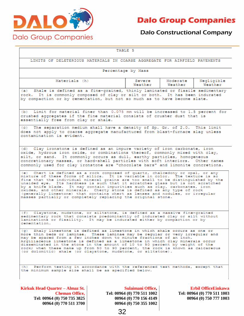
2.2.2.4 Deleterious Materials - Airfield Pavements
The amount of deleterious material in each size group of coarse aggregate shall not exceed the limits
shown in Table 5 below, determined in accordance with the test methods shown.
31
Erbil OfficeEinkawa
Tel: 00964 (0) 770 511 1003
00964 (0) 750 777 1003
Sulaimani Office,
Tel: 00964 (0) 770 511 1002
00964 (0) 770 156 4149
00964 (0) 750 355 1002
Kirkuk Head Quarter – Almaz St.
Cheman Office,
Tel: 00964 (0) 750 735 3825
00964 (0) 770 511 3700
32

Erbil OfficeEinkawa
Tel: 00964 (0) 770 511 1003
00964 (0) 750 777 1003
Sulaimani Office,
Tel: 00964 (0) 770 511 1002
00964 (0) 770 156 4149
00964 (0) 750 355 1002
Kirkuk Head Quarter – Almaz St.
Cheman Office,
Tel: 00964 (0) 750 735 3825
00964 (0) 770 511 3700
2.2.2.5 Testing Sequence/Deleterious Materials in Coarse Aggregate - Airfields Only
The Contractor will not be entitled to any extension of time or additional payment due to any delays
caused by the testing, evaluation, or personnel requirements. The size of the coarse aggregate sample
shall be at least 90 kg for the 19 mm and larger maximum size and 12 kg for the 4.75 to 19 mm coarse
aggregate and 5 kg for the fine aggregate. Provide facilities for the ready procurement of representative
test samples. The testing procedure on each sample of coarse aggregate for compliance with limits on
deleterious materials shall be as follows:
2.2.2.6 Deleterious Material - Road Pavements
The amount of deleterious material in each size group of coarse aggregate shall not exceed the limits
in the following table when tested as indicated.
The limit for material finer than the 0.075 mm sieve will be increased to 1.5 percent for crushed
aggregates consisting of crusher dust that is essentially free from clay or shale. The separation
medium for lightweight particles shall have a density of 2.0 specific gravity. This limit does not apply
to coarse aggregate manufactured from blast-furnace slag unless contamination is evident.
33

Erbil OfficeEinkawa
Tel: 00964 (0) 770 511 1003
00964 (0) 750 777 1003
Sulaimani Office,
Tel: 00964 (0) 770 511 1002
00964 (0) 770 156 4149
00964 (0) 750 355 1002
Kirkuk Head Quarter – Almaz St.
Cheman Office,
Tel: 00964 (0) 750 735 3825
00964 (0) 770 511 3700
2.2.3 Fine Aggregate
2.2.3.1 Composition
Fine aggregate shall consist of natural sand, manufactured sand, or a combination of the two, and
shall be composed of clean, hard, durable particles meeting the requirements of ASTM C33/C33M.
Aggregate used for paving compass calibration hardstands shall be free of materials having
undesirable magnetic properties, including magnetite in granite, high-iron minerals in traprock, and
pyrite in limestone. Each type of fine aggregate shall be stockpiled and batched separately. Particles
of the fine aggregate shall be generally spherical or cubical in shape.
2.2.3.2 Grading
Grading of the fine aggregate, as delivered to the mixer, shall conform to the requirements of ASTM
C33/C33M and shall have a fineness modulus of not less than 2.50 nor more than 3.40.
2.2.3.3 Deleterious Material
The amount of deleterious material in the fine aggregate shall not exceed the following limits by
mass:
Material Percentage by Mass
34

Erbil OfficeEinkawa
Tel: 00964 (0) 770 511 1003
00964 (0) 750 777 1003
Sulaimani Office,
Tel: 00964 (0) 770 511 1002
00964 (0) 770 156 4149
00964 (0) 750 355 1002
Kirkuk Head Quarter – Almaz St.
Cheman Office,
Tel: 00964 (0) 750 735 3825
00964 (0) 770 511 3700
2.3 CHEMICAL ADMIXTURES
2.3.1 General Requirements
Chemical admixtures may only be used when the specific admixture type and manufacturer is the
same material used in the mixture proportioning studies. The air-entraining admixture shall conform
to ASTM C260/C260M. An accelerator conforming to ASTM C494/C494M, Type C, may be used only
when specified in paragraph: SPECIFIED CONCRETE STRENGTH AND OTHER PROPERTIES
below and shall not be used to reduce the amount of cementitious material used. Calcium chloride
and admixtures containing calcium chloride shall not be used. Retarding or water-reducing
admixture shall meet the requirements of ASTM C494/C494M, Type A, B, or D, except that the 6-
month and 1-year compressive strength tests are waived. ASTM C494/C494M, Type F and G high
range water reducing admixtures and ASTM C1017/C1017M flowable admixtures shall not be used.
2.3.2 Lithium Nitrate
The lithium admixture shall be a nominal 30 percent aqueous solution of Lithium Nitrate, with a
density of 1.2 kg/L, and shall have the approximate chemical form as shown below:
35
Erbil OfficeEinkawa
Tel: 00964 (0) 770 511 1003
00964 (0) 750 777 1003
Sulaimani Office,
Tel: 00964 (0) 770 511 1002
00964 (0) 770 156 4149
00964 (0) 750 355 1002
Kirkuk Head Quarter – Almaz St.
Cheman Office,
Tel: 00964 (0) 750 735 3825
00964 (0) 770 511 3700
Provide a trained representative to supervise the lithium nitrate admixture dispensing and mixing
operations.
2.4 MEMBRANE FORMING CURING COMPOUND
Membrane forming curing compound shall be a white pigmented compound conforming to COE CRD-
C 300. .
2.5 WATER
Water for mixing and curing shall be fresh, clean, potable, and free of injurious amounts of oil, acid,
salt, or alkali, except that non-potable water, or water from concrete production operations, may be
used if it meets the requirements of ASTM C1602/C1602M.
2.6 JOINT MATERIALS
2.6.1 Expansion Joint Material
Expansion joint filler shall be a preformed material conforming to ASTM D1752 Type II. Expansion
joint filler shall be 19 mm thick, unless otherwise indicated, and shall be furnished in a single full
depth piece.
2.6.2 Slip Joint Material
Slip joint material shall be 6 mm thick expansion joint filler, unless otherwise indicated, conforming to
paragraph: Expansion Joint Material.
36

Erbil OfficeEinkawa
Tel: 00964 (0) 770 511 1003
00964 (0) 750 777 1003
Sulaimani Office,
Tel: 00964 (0) 770 511 1002
00964 (0) 770 156 4149
00964 (0) 750 355 1002
Kirkuk Head Quarter – Almaz St.
Cheman Office,
Tel: 00964 (0) 750 735 3825
00964 (0) 770 511 3700
2.7 REINFORCING
All reinforcement shall be free from loose, flaky rust, loose scale, oil, grease, mud, or other coatings
that might reduce the bond with concrete. Removal of thin powdery rust and tight rust is not
required. However, reinforcing steel which is rusted to the extent that it does not conform to the
required dimensions or mechanical properties shall not be used.
2.7.1 Reinforcing Bars and Bar Mats
Reinforcing bars shall conform to ASTM A615/A615M, billet-steel, Grade 60 . Bar mats shall conform to
ASTM A184/A184M. The bar members may be billet rail or axle steel.
2.7.2 Welded Wire Reinforcement
Welded Wire Reinforcement shall be deformed or smooth, conforming to ASTM A1064/A1064M, and
shall be furnished in flat sheets.
2.8 DOWELS AND TIE BARS
2.8.1 Dowels
Dowels shall be single piece bars fabricated or cut to length at the shop or mill before delivery to
the site. Dowels shall be free of loose, flaky rust and loose scale and shall be clean and straight.
Dowels may be sheared to length provided that the deformation from true shape caused by shearing
does not exceed 1 mm on the diameter of the dowel and does not extend more than 1 mm from the end
of the dowel. Dowels shall be plain (non-deformed) steel bars conforming to ASTM A615/A615M,
Grade 40 or 60; ASTM A996/A996M, Grade 50 or 60. Dowel bars shall be epoxy coated in conformance
with ASTM A775/A775M. Grout retention rings shall be fully circular metal or plastic devices capable
of supporting the dowel until the epoxy hardens. Dowel sleeves or inserts are not permitted.
37

Erbil OfficeEinkawa
Tel: 00964 (0) 770 511 1003
00964 (0) 750 777 1003
Sulaimani Office,
Tel: 00964 (0) 770 511 1002
00964 (0) 770 156 4149
00964 (0) 750 355 1002
Kirkuk Head Quarter – Almaz St.
Cheman Office,
Tel: 00964 (0) 750 735 3825
00964 (0) 770 511 3700
2.8.2 Dowel Bar Assemblies
Dowel bar assemblies shall consist of a framework of metal bars or wires arranged to provide rigid
support for the dowels throughout the paving operation, with a minimum of four continuous bars or
wires extending along the joint line. The dowels shall be welded to the assembly or held firmly by
mechanical locking arrangements that will prevent them from rising, sliding out, or becoming distorted
during paving operations.
2.8.3 Tie Bars
Tie bars shall be deformed steel bars conforming to ASTM A615/A615M, or ASTM A996/A996M,
Grade 60 , and of the sizes and dimensions indicated. Deformed rail steel bars and high-strength billet
or axle steel bars, Grade 50 or higher, shall not be used for bars that are bent and straightened during
construction.
2.9 EPOXY RESIN
All epoxy-resin materials shall be two-component materials conforming to the requirements of ASTM
C881/C881M, Class as appropriate for each application temperature to be encountered, except that in
addition, the materials shall meet the following requirements:
a. Material for use for embedding dowels and anchor bolts shall be Type IV, Grade 3.
b. Material for use as patching materials for complete filling of spalls and other voids and for use in
preparing epoxy resin mortar shall be Type III, Grade as approved.
c. Material for use for injecting cracks shall be Type IV, Grade 1.
d. Material for bonding freshly mixed portland cement concrete or mortar or freshly mixed epoxy
resin concrete or mortar to hardened concrete shall be Type V, Grade as approved.
38

Erbil OfficeEinkawa
Tel: 00964 (0) 770 511 1003
00964 (0) 750 777 1003
Sulaimani Office,
Tel: 00964 (0) 770 511 1002
00964 (0) 770 156 4149
00964 (0) 750 355 1002
Kirkuk Head Quarter – Almaz St.
Cheman Office,
Tel: 00964 (0) 750 735 3825
00964 (0) 770 511 3700
2.10 EQUIPMENT
All plant, equipment, tools, and machines used in the work shall be maintained in satisfactory working
conditions at all times. Submit the following:
a. Details and data on the batching and mixing plant prior to plant assembly including manufacturer's
literature showing that the equipment meets all requirements specified herein.
b. Obtain National Ready Mixed Concrete Association (NRMCA) certification of the concrete plant.
The concrete plant shall be inspected by an engineer approved by the NRMCA. A list of NRMCA
approved engineers is available on the NRMCA website at http://www.nrmca.org. All fees and costs
associated with this inspection shall be paid by the Contractor. Submit a copy of the NRMCA QC
Manual Section 3 Concrete Plant Certification Checklist, NRMCA Certificate of Conformance, and
Calibration documentation on all measuring and weighing devices prior to uniformity testing.
c. A description of the equipment proposed for transporting concrete mixture from the central mixing
plant to the paving equipment.
d. A description of the equipment proposed for the machine and hand placing, consolidating and
curing of the concrete mixture. Manufacturer's literature on the paver and finisher, together with
the manufacturer's written instructions on adjustments and operating procedures necessary to assure a
tight, smooth surface on the concrete pavement. The literature shall show that the equipment
meets all details of these specifications.
2.10.1 Batching and Mixing Plant
a. Location: The batching and mixing plant shall be located on project site as indicated on the
drawings. Water and electrical power are available on the project site. There shall be operable
telephonic or radio communication between the plant and the placing site at all times concreting is
taking place.
39

Erbil OfficeEinkawa
Tel: 00964 (0) 770 511 1003
00964 (0) 750 777 1003
Sulaimani Office,
Tel: 00964 (0) 770 511 1002
00964 (0) 770 156 4149
00964 (0) 750 355 1002
Kirkuk Head Quarter – Almaz St.
Cheman Office,
Tel: 00964 (0) 750 735 3825
00964 (0) 770 511 3700
b. Type and Capacity: The batching and mixing plant shall be a stationary-type central mix plant,
including permanent installations or portable/relocatable plants installed on stable foundations. The
plant shall be designed and operated to produce concrete within the specified tolerances, and shall
have a capacity of at least 100 cubic meters per hour. The batching and mixing plant shall conform
to the requirements of NRMCA QC 3 including provisions addressing:
1. Material Storage and Handling
2. Batching Equipment
3. Central Mixer
4. Ticketing System
5. Delivery System
c. Tolerances: The following tolerances shall apply.
For volumetric batching equipment for water and admixtures, the above numeric tolerances shall apply
to the required volume of material being batched. Concentrated admixtures shall be uniformly diluted,
if necessary, to provide sufficient volume per batch to ensure that the batchers will consistently
operate within the above tolerance.
d. Moisture Control: The plant shall be capable of ready adjustment to compensate for the varying
moisture contents of the aggregates and to change the quantities of the materials being batched. An
electric moisture meter complying with the provisions of COE CRD-C 143 shall be provided for
measuring of moisture in the fine aggregate. The sensing element shall be arranged so that
40

Erbil OfficeEinkawa
Tel: 00964 (0) 770 511 1003
00964 (0) 750 777 1003
Sulaimani Office,
Tel: 00964 (0) 770 511 1002
00964 (0) 770 156 4149
00964 (0) 750 355 1002
Kirkuk Head Quarter – Almaz St.
Cheman Office,
Tel: 00964 (0) 750 735 3825
00964 (0) 770 511 3700
measurement is made near the batcher charging gate of the fine aggregate bin or in the fine aggregate
batcher.
2.10.2 Concrete Mixers
a. General: Mixers shall be stationary or truck mixers. Mixers shall be capable of combining the
materials into a uniform mixture and of discharging this mixture without segregation. The mixers
shall not be charged in excess of the capacity recommended by the manufacturer. The mixers shall be
operated at the drum or mixing blade speed designated by the manufacturer. The mixers shall be
maintained in satisfactory operating condition, and the mixer drums shall be kept free of hardened
concrete. Mixer blades or paddles shall be replaced when worn down more than 10 percent of their
depth when compared with the manufacturer's dimension for new blades or paddles.
b. Stationary: Stationary mixers shall be drum or pan mixers. Mixers shall be provided with an
acceptable device to lock the discharge mechanism until the required mixing time has elapsed.
c. Mixing Time and Uniformity for Stationary Mixers: For stationary mixers, before uniformity data
are available, the mixing time for each batch after all solid materials are in the mixer, provided that
all of the mixing water is introduced before one-fourth of the mixing time has elapsed, shall be 1
minute for mixers having a capacity of 0.75 cubic meter. For mixers of greater capacity, this
minimum time shall be increased 20 seconds for each additional cubic meter or fraction thereof. After
results of uniformity tests are available, the mixing time may be reduced to the minimum time
required to meet uniformity requirements; but if uniformity requirements are not being met, the mixing
time shall be increased as directed. The mixing time for full batch production shall be a
minimum of 75 seconds. Mixer performance tests at new mixing times shall be performed
immediately after any change in mixing time. The Regular Test sequence shall be conducted for
initial determination of the mixing time or as directed. When regular testing is performed, the
concrete shall meet the limits of any five of the six uniformity requirements listed in Table 1 below.
41

Erbil OfficeEinkawa
Tel: 00964 (0) 770 511 1003
00964 (0) 750 777 1003
Sulaimani Office,
Tel: 00964 (0) 770 511 1002
00964 (0) 770 156 4149
00964 (0) 750 355 1002
Kirkuk Head Quarter – Almaz St.
Cheman Office,
Tel: 00964 (0) 750 735 3825
00964 (0) 770 511 3700
d. The Abbreviated Test sequence shall be conducted for production concrete verification at the
frequency specified in Table 6. When abbreviated testing is performed, the concrete shall meet only
those requirements listed for abbreviated testing. The concrete proportions used for uniformity tests
shall be as used on the project. Regular testing shall consist of performing all six tests
on three batches of concrete. The range for regular testing shall be the average of the ranges of the
three batches. Abbreviated testing shall consist of performing the three required tests on a
single batch of concrete. The range for abbreviated testing shall be the range for one batch. If more than
one mixer is used and all are identical in terms of make, type, capacity, condition, speed of
rotation, etc., the results of tests on one of the mixers shall apply to the others, subject to the
approval of the Contracting Officer. All mixer performance (uniformity) testing shall be
performed in accordance with COE CRD-C 55 and with paragraph titled
TESTING AND INSPECTION FOR CONTRACTOR QUALITY CONTROL in PART 3.
42

Erbil OfficeEinkawa
Tel: 00964 (0) 770 511 1003
00964 (0) 750 777 1003
Sulaimani Office,
Tel: 00964 (0) 770 511 1002
00964 (0) 770 156 4149
00964 (0) 750 355 1002
Kirkuk Head Quarter – Almaz St.
Cheman Office,
Tel: 00964 (0) 750 735 3825
00964 (0) 770 511 3700
e. Truck: Truck mixers shall not be used for mixing or transporting slipformed paving concrete. The
only truck mixers used for mixing or transporting paving concrete shall be those designed
with extra large blading and rear opening specifically for low-slump paving concrete. Truck mixers,
the mixing of concrete therein, and concrete uniformity and testing thereof shall conform to the
requirements of ASTM C94/C94M. The number of revolutions between 70 to 100 for truck-mixed
concrete and the number of revolutions for shrink-mixed concrete shall be determined by uniformity
tests as specified in ASTM C94/C94M and in requirements for mixer performance stated in paragraph
TESTING AND INSPECTION FOR CONTRACTOR QUALITY CONTROL in PART 3. If
requirements for the uniformity of concrete are not met with 100 revolutions of mixing after all
ingredients including water are in the truck mixer drum, the mixer shall not be used until the
condition is corrected. Water shall not be added after the initial introduction of mixing water except,
when on arrival at the job site, the slump is less than specified and the water-cement ratio is less
than that given as a maximum in the approved mixture. Additional water may be added to bring the
slump within the specified range provided the approved water-cement ratio is not exceeded. Water
shall be injected into the head of the mixer (end opposite the discharge opening) drum under pressure,
and the drum or blades shall be turned a minimum of 30 additional revolutions at mixing speed.
Water shall not be added to the batch at any later time.
2.10.3 Transporting Equipment
Slipform concrete shall be transported to the paving site in nonagitating equipment conforming to
ASTM C94/C94M or in approved agitators. Fixed form concrete shall be transported in approved
truck mixers designed with extra large blading and rear opening specifically for low slump concrete.
All transporting equipment shall be designed and operated to deliver and discharge the required
concrete mixture completely without segregation.
43

Erbil OfficeEinkawa
Tel: 00964 (0) 770 511 1003
00964 (0) 750 777 1003
Sulaimani Office,
Tel: 00964 (0) 770 511 1002
00964 (0) 770 156 4149
00964 (0) 750 355 1002
Kirkuk Head Quarter – Almaz St.
Cheman Office,
Tel: 00964 (0) 750 735 3825
00964 (0) 770 511 3700
2.10.4 Transfer and Spreading Equipment
Equipment for transferring concrete from the transporting equipment to the paving lane in front of the
paver shall be specially manufactured, self-propelled transfer equipment which will accept the concrete
outside the paving lane and will transfer and spread it evenly across the paving lane in front of the
paver and strike off the surface evenly to a depth which permits the paver to operate efficiently.
2.10.5 Paver-Finisher
The following items a through e apply to both fixed-form and slip-form paver-finishers. Item f is
applicable to fixed-form paver-finishers and item g is applicable to slip-form paver-finishers.
a. General: The paver-finisher shall be a heavy-duty, self-propelled machine designed specifically for
paving and finishing high quality pavement. The paver-finisher shall weigh at least 3280 kg/m of lane
width, and shall be powered by an engine having at least 15,000 W/m of lane width. The paver-
finisher shall spread, consolidate, and shape the plastic concrete to the desired cross section in one
pass. The mechanisms for forming the pavement shall be easily adjustable in width and thickness and
for required crown. In addition to other spreaders required by paragraph above, the paver-finisher
shall be equipped with a full width knock-down auger or paddle mechanism, capable of operating in
both directions, which will evenly spread the fresh concrete in front of the screed or extrusion plate.
b. Vibrators: Immersion vibrators shall be gang mounted at the front of the paver on a frame
equipped with suitable controls so that all vibrators can be operated at any desired depth within the
slab or completely withdrawn from the concrete, as required. The vibrators shall be automatically
controlled so that they will be immediately stopped as forward motion of the paver ceases. The
spacing of the immersion vibrators across the paving lane shall be as necessary to properly consolidate
the concrete, but the clear distance between vibrators shall not exceed 750 mm. The outside vibrators
shall not be more than 300 mm from the lane edge. Spud vibrators shall operate at a frequency of
not less than 135 Hz and an amplitude of not less than 0.75 mm, as determined by COE CRD-C 521.
44

Erbil OfficeEinkawa
Tel: 00964 (0) 770 511 1003
00964 (0) 750 777 1003
Sulaimani Office,
Tel: 00964 (0) 770 511 1002
00964 (0) 770 156 4149
00964 (0) 750 355 1002
Kirkuk Head Quarter – Almaz St.
Cheman Office,
Tel: 00964 (0) 750 735 3825
00964 (0) 770 511 3700
c. Screed or Extrusion Plate: The paver-finisher shall be equipped with a transversely oscillating
screed or an extrusion plate to shape, compact, and smooth the surface and shall so finish the surface
that no significant amount of hand finishing, except use of cutting straightedges, is required. The
screed or extrusion plate shall be constructed to provide adjustment for crown in the pavement. The
entire machine shall provide adjustment for variation in lane width or thickness and to prevent more
than 200 mm of the screed or extrusion plate extending over previously placed concrete on either
end when paving fill-in lanes. Machines that cause displacement of properly installed forms or cause
ruts or indentations in the prepared underlying materials and machines that cause frequent delays due
to mechanical failures shall be replaced as directed.
d. Longitudinal Mechanical Float: A longitudinal mechanical float may be used. If used, the float
shall be specially designed and manufactured to smooth and finish the pavement surface without
working excess paste to the surface. It shall be rigidly attached to the rear of the paver-finisher or
to a separate self-propelled frame spanning the paving lane. The float plate shall be at least
1.5 m long by 200 mm wide and shall automatically be oscillated in the longitudinal direction while
slowly moving from edge to edge of the paving lane, with the float plate in contact with the surface
at all times.
e. Other Types of Finishing Equipment: Clary screeds, other rotating tube floats, or bridge deck
finishers are not allowed on mainline paving, but may be allowed on irregular or odd-shaped slabs,
and near buildings or trench drains, subject to the Contracting Officer's approval. Bridge deck
finishers shall have a minimum operating weight of 3400 kg and shall have a transversely operating
carriage containing a knock-down auger and a minimum of two immersion vibrators. Vibrating screeds
or pans shall be used only for isolated slabs where hand finishing is permitted as specified, and only
where specifically approved.
f. Fixed Forms: The paver-finisher shall be equipped with wheels designed to ride the forms, keep it
aligned with the forms, and spread the load so as to prevent deformation of the forms. Paver-finishers
45

Erbil OfficeEinkawa
Tel: 00964 (0) 770 511 1003
00964 (0) 750 777 1003
Sulaimani Office,
Tel: 00964 (0) 770 511 1002
00964 (0) 770 156 4149
00964 (0) 750 355 1002
Kirkuk Head Quarter – Almaz St.
Cheman Office,
Tel: 00964 (0) 750 735 3825
00964 (0) 770 511 3700
traveling on guide rails located outside the paving lane shall be equipped with wheels when traveling
on new or existing concrete to remain.
g. Slipform: The slipform paver-finisher shall be automatically controlled and crawler mounted with
padded tracks so as to be completely stable under all operating conditions. The paver-finisher shall
finish the surface and edges so that no edge slump beyond allowable tolerance occurs. Suitable
moving side forms shall be provided that are adjustable and will produce smooth, even edges,
perpendicular to the top surface and meeting specification requirements for alignment and freedom
from edge slump.
2.10.6 Curing Equipment
Equipment for applying membrane-forming curing compound shall be mounted on a self-propelled
frame that spans the paving lane. The reservoir for curing compound shall be constantly mechanically
(not air) agitated during operation and shall contain means for completely draining the reservoir. The
spraying system shall consist of a mechanically powered pump which will maintain constant pressure
during operation, an operable pressure gauge, and either a series of spray nozzles evenly spaced
across the lane to give uniformly overlapping coverage or a single spray nozzle which is mounted on
a carriage which automatically traverses the lane width at a speed correlated with the forward
movement of the overall frame. All spray nozzles shall be protected with wind screens.
Calibrate the spraying system in accordance with ASTM D2995, Method A, for the rate of application
required in paragraph: Membrane Curing. Any hand-operated sprayers allowed by that paragraph shall
be compressed air supplied by a mechanical air compressor. If the curing equipment fails
to apply an even coating of compound at the specified rate, it shall immediately be replaced.
46

Erbil OfficeEinkawa
Tel: 00964 (0) 770 511 1003
00964 (0) 750 777 1003
Sulaimani Office,
Tel: 00964 (0) 770 511 1002
00964 (0) 770 156 4149
00964 (0) 750 355 1002
Kirkuk Head Quarter – Almaz St.
Cheman Office,
Tel: 00964 (0) 750 735 3825
00964 (0) 770 511 3700
2.10.7 Texturing Equipment
a. General: Texturing equipment shall be as specified below. Before use, the texturing equipment
shall be demonstrated on a test section, and the equipment shall be modified as necessary to produce
the texture directed.b. Burlap Drag: A burlap drag shall be securely attached to a separate
wheel mounted frame spanning the paving lane or to one of the other similar pieces of equipment.
Length of the material shall provide 600 to 900 mm dragging flat on the pavement surface. Width
shall be at least equal to the width of the slab. The material shall be clean, reasonably new burlap,
completely saturated with water before attachment to the frame, always resaturated before start of use,
and kept clean and saturated during use. Burlap shall conform to
AASHTO M 182, Class 3 or 4.
c. Broom: Surface texture shall be applied using an approved mechanical stiff bristle broom drag of
a type that will uniformly score the surface transverse to the pavement center line. The broom shall
be capable of traversing the full width of the pavement in a single pass at a uniform speed and with
a uniform pressure. The scores shall be uniform in appearance and approximately 1.5 mm in depth
but not more than 3 mm in depth.
2.10.8 Sawing Equipment
Equipment for sawing joints and for other similar sawing of concrete shall be standard diamond-type
concrete saws mounted on a wheeled chassis which can be easily guided to follow the required
alignment. Blades shall be diamond tipped. If demonstrated to operate properly, abrasive blades may
be used. Provide spares as required to maintain the required sawing rate. Wheel saws used in the
removal of concrete shall be saws with large diameter tungsten carbide tipped blades mounted on a
heavy-duty chassis which will produce a saw kerf at least 40 mm wide. All saws shall be capable of
sawing to the full depth required.
Early-entry saws may be used, subject to demonstration and approval of the Contracting Officer. No
change to the initial sawcut depth shall be permitted.
47

Erbil OfficeEinkawa
Tel: 00964 (0) 770 511 1003
00964 (0) 750 777 1003
Sulaimani Office,
Tel: 00964 (0) 770 511 1002
00964 (0) 770 156 4149
00964 (0) 750 355 1002
Kirkuk Head Quarter – Almaz St.
Cheman Office,
Tel: 00964 (0) 750 735 3825
00964 (0) 770 511 3700
2.10.9 Straightedge
Furnish and maintain at the job site, in good condition, one 4 m straightedge for each paving train for
testing the hardened portland cement concrete surfaces. These straightedges shall be constructed of
aluminum or magnesium alloy and shall have blades of box or box-girder cross section with flat
bottom, adequately reinforced to insure rigidity and accuracy. Straightedges shall have handles for
operation on the pavement.
2.11 SPECIFIED CONCRETE STRENGTH AND OTHER PROPERTIES
2.11.1 Specified Flexural Strength
Specified flexural strength, R, for concrete is 4.2 MPa at 28 days, as determined by Maximum
allowable water-cementitious material ratio is 0.45. The water-cementitious material ratio will be the
equivalent water-cement ratio as determined by conversion from the weight ratio of water to cement
plus SCM by the mass equivalency method described in ACI 211.1. The concrete shall be air-
entrained with a total air content of 4 plus or minus 1.5 percentage points, at the point of placement.
Air content shall be determined in accordance with ASTM C231/C231M. The maximum allowable
slump of the concrete at the point of placement shall be 50 mm for pavement constructed with fixed
forms. For slipformed pavement, at the start of the project, select a maximum allowable slump
which will produce in-place pavement meeting the specified tolerances for control of edge slump.
The selected slump shall be applicable to both pilot and fill-in lanes.
2.11.2 Concrete Temperature
The temperature of the concrete as delivered shall conform to the requirements of paragraphs, Paving
in Hot Weather and Paving in Cold Weather, in PART 3. Temperature of concrete shall be
determined in accordance with ASTM C1064/C1064M.
48

Erbil OfficeEinkawa
Tel: 00964 (0) 770 511 1003
00964 (0) 750 777 1003
Sulaimani Office,
Tel: 00964 (0) 770 511 1002
00964 (0) 770 156 4149
00964 (0) 750 355 1002
Kirkuk Head Quarter – Almaz St.
Cheman Office,
Tel: 00964 (0) 750 735 3825
00964 (0) 770 511 3700
2.11.3 Concrete Strength for Final Acceptance
, and no individual set (2 specimens per sublot) in the lot are 170 kPa or more below the equivalent
'Specified Flexural Strength'. If any lot or sublot, respectively, fails to meet the above criteria, the lot
or sublot shall be removed and replaced at no additional cost to the Government. This is in addition
to and does not replace the average strength required for day-to-day CQC operations as specified in
paragraph: Average CQC Flexural Strength Required for Mixtures, below.
2.12 MIXTURE PROPORTIONS
2.12.1 Composition
Concrete shall be composed of cementitious material, water, fine and coarse aggregates, and
admixtures. Supplementary Cementitious Materials (SCM) choice and usage shall be in accordance
with paragraph: Supplementary Cementitious Materials (SCM) Content. The total cementitious material
content shall be at least 310 kg/cubic meter. Admixtures shall consist of air entraining admixture and
may also include, as approved, water-reducing admixture.
2.12.2 Proportioning Studies
Trial design batches, mixture proportioning studies, and testing requirements are the responsibility of
the Contractor. Submit the results of the mixture proportioning studies signed and stamped by the
registered professional engineer having technical responsibility for the mix design study, and submitted
at least 30 days prior to commencing concrete placing operations. The results shall include a
statement giving the maximum nominal coarse aggregate size and the weights and volumes of each
ingredient proportioned on a one cubic meter basis. Aggregate quantities shall be based on the mass in
a saturated surface dry condition. The recommended mixture proportions shall be accompanied
by test results demonstrating that the proportions selected will produce concrete of the qualities
indicated. Trial mixtures having proportions, slumps, and air content suitable for the work shall be
49

Erbil OfficeEinkawa
Tel: 00964 (0) 770 511 1003
00964 (0) 750 777 1003
Sulaimani Office,
Tel: 00964 (0) 770 511 1002
00964 (0) 770 156 4149
00964 (0) 750 355 1002
Kirkuk Head Quarter – Almaz St.
Cheman Office,
Tel: 00964 (0) 750 735 3825
00964 (0) 770 511 3700
based on methodology described in ACI 211.1, modified as necessary to accommodate flexural strength.
Submit test results including:
a. Coarse and fine aggregate gradations and plots.
b. Combined aggregate gradation and coarseness/workability plots.
c. Coarse aggregate quality test results, include deleterious
materials.
d. Fine aggregate quality test results.
e. Mill certificates for cement and supplemental cementitious
materials.
f. Certified test results for air entraining, water reducing,
retarding, non-chloride accelerating admixtures.
g. Specified flexural strength, slump, and air content.
h. Documentation of required average CQC flexural strength, Ra.
i. Recommended proportions/volumes for proposed mixture and each of
three trial water-cementitious materials ratios.
j. Individual beam breaks.
k. Flexural strength summaries and plots.
l. Correlation ratios for acceptance testing and CQC testing.
m. Historical record of test results, documenting production standard deviation (if available).
2.12.2.1 Water-Cement Ratio
At least three different water-cement ratios, which will produce a range of strength encompassing that
required on the project, shall be used. The maximum allowable water-cement ratio required in
paragraph: Specified Flexural Strength, above will be the equivalent water-cement ratio. Laboratory
trial mixtures shall be proportioned for maximum permitted slump and air content.
50

Erbil OfficeEinkawa
Tel: 00964 (0) 770 511 1003
00964 (0) 750 777 1003
Sulaimani Office,
Tel: 00964 (0) 770 511 1002
00964 (0) 770 156 4149
00964 (0) 750 355 1002
Kirkuk Head Quarter – Almaz St.
Cheman Office,
Tel: 00964 (0) 750 735 3825
00964 (0) 770 511 3700
2.12.2.2 Trial Mixture Studies
Separate sets of trial mixture studies shall be made for each combination of cementitious materials and
each combination of admixtures proposed for use. No combination of either shall be used until
proven by such studies, except that, if approved in writing and otherwise permitted by these
specifications, an accelerator or a retarder may be used without separate trial mixture study. Separate
trial mixture studies shall also be made for concrete for each placing method (slip form, fixed form,
or hand placement) proposed. The temperature of concrete in each trial batch shall be reported.
Each mixture shall be designed to promote easy and suitable concrete placement, consolidation
and finishing, and to prevent segregation and excessive bleeding.
2.12.2.3 Mixture Proportioning for Flexural Strength
The following step by step procedure shall be followed:
2.12.3 Average CQC Flexural Strength Required for Mixtures
In order to ensure meeting the strength requirements specified in paragraph: SPECIFIED CONCRETE
STRENGTH AND OTHER PROPERTIES above, during production, the mixture proportions selected
during mixture proportioning studies and used during construction shall produce a required average
CQC flexural strength exceeding the specified strength, R, by the amount indicated below. This
required average CQC flexural strength, Ra, will be used only for CQC operations as specified in
paragraph: TESTING AND INSPECTION FOR CONTRACTOR QUALITY CONTROL in PART
3 and as specified in the previous paragraph. During production, the required Ra shall be adjusted ,
as appropriate and as approved, based on the standard deviation of -day strengths being attained
during paving.
51

Erbil OfficeEinkawa
Tel: 00964 (0) 770 511 1003
00964 (0) 750 777 1003
Sulaimani Office,
Tel: 00964 (0) 770 511 1002
00964 (0) 770 156 4149
00964 (0) 750 355 1002
Kirkuk Head Quarter – Almaz St.
Cheman Office,
Tel: 00964 (0) 750 735 3825
00964 (0) 770 511 3700
a. From Previous Test Records: Where a concrete production facility has previous test records
current to within 18 months, a standard deviation shall be established in accordance with the
applicable provisions of ACI 214R. Test records from which a standard deviation is calculated shall
represent materials, quality control procedures, and conditions similar to those expected, shall
represent concrete produced to meet a specified flexural strength or strengths within 1 MPa of the 28 -
day flexural strength specified for the proposed work, and shall consist of at least 30 consecutive
tests. Perform verification testing, as directed by the Contracting Officer, to document the current
strength. A strength test shall be the average of the strengths of two specimens made from the same
sample of concrete and tested at 28 days. Required average CQC flexural strength, Ra, used as the
basis for selection of concrete proportions shall be the value from the equation that follows, using
the standard deviation as determined above:
Ra = R + 1.34S
Where: S = standard deviation
R = specified flexural strength
Ra = required average flexural strength
Where a concrete production facility does not have test records meeting the requirements above but
does have a record based on 15 to 29 consecutive tests, a standard deviation shall be established as
the product of the calculated standard deviation and a modification factor from the following table:
52

Erbil OfficeEinkawa
Tel: 00964 (0) 770 511 1003
00964 (0) 750 777 1003
Sulaimani Office,
Tel: 00964 (0) 770 511 1002
00964 (0) 770 156 4149
00964 (0) 750 355 1002
Kirkuk Head Quarter – Almaz St.
Cheman Office,
Tel: 00964 (0) 750 735 3825
00964 (0) 770 511 3700
b. Without Previous Test Records: When a concrete production facility does not have sufficient field
strength test records for calculation of the standard deviation, the required average strength, Ra, shall
be determined by adding 15 percent to the specified flexural strength, R.
PART 3 EXECUTION
3.1 PREPARATION FOR PAVING
Before commencing paving, perform the following. If used, forms shall be in place, cleaned, coated,
and adequately supported. Any reinforcing steel needed shall be at the paving site. All transporting
and transfer equipment shall be ready for use, clean, and free of hardened concrete and foreign
material. Equipment for spreading, consolidating, screeding, finishing, and texturing concrete shall be
at the paving site, clean and in proper working order. All equipment and material for curing and for
protecting concrete from weather or mechanical damage shall be at the paving site, in proper working
condition, and in sufficient amount for the entire placement.
3.1.1 Weather Precaution
When windy conditions during paving appear probable, equipment and material shall be at the paving
site to provide windbreaks, shading, fogging, or other action to prevent plastic shrinkage cracking or
other damaging drying of the concrete.
3.1.2 Proposed Techniques
Submit placing and protection methods; paving sequence; jointing pattern; data on curing equipment
and profilographs; demolition of existing pavements, as specified; pavement diamond grinding
equipment and procedures. Submit for approval the following items:
53
Erbil OfficeEinkawa
Tel: 00964 (0) 770 511 1003
00964 (0) 750 777 1003
Sulaimani Office,
Tel: 00964 (0) 770 511 1002
00964 (0) 770 156 4149
00964 (0) 750 355 1002
Kirkuk Head Quarter – Almaz St.
Cheman Office,
Tel: 00964 (0) 750 735 3825
00964 (0) 770 511 3700
a. A description of the placing and protection methods proposed when concrete is to be placed in or
exposed to hot, cold, or rainy weather conditions.
b. A detailed paving sequence plan and proposed paving pattern showing all planned construction
joints; transverse and longitudinal dowel bar spacing; and identifying pilot lanes and hand placement
areas. No deviation from the jointing pattern shown on the drawings shall be made without written
approval of the design engineer.
c. Plan and equipment proposed to control alignment of sawn joints within the specified tolerances.
d. Data on the curing equipment, media and methods to be used.
e. Data on profilograph and methods to measure pavement smoothness.
f. Pavement demolition work plan, presenting the proposed methods and equipment to remove
existing pavement and protect pavement to remain in place.
3.2 CONDITIONING OF UNDERLYING MATERIAL
3.2.1 General Procedures
Underlying material, upon which concrete is to be placed shall be clean, damp, and free from debris,
waste concrete or cement, frost, ice, standing or running water. Prior to setting forms or placement
of concrete, the underlying material shall be well drained and shall have been satisfactorily graded by
string-line controlled, automated, trimmer/fine grader and uniformly compacted in accordance with the
applicable Section of these specifications. The surface of the underlying material shall be tested as to
crown, elevation, and density in advance of setting forms or of concrete placement using slip-form
techniques. High areas shall be trimmed to proper elevation. Low areas shall be filled and
compacted to a condition similar to that of surrounding grade, or filled with concrete monolithically
with the pavement. Low areas filled with concrete shall not be cored for thickness to avoid biasing
the average thickness used for evaluation and payment adjustment. Any underlying material disturbed
by construction operations shall be reworked and recompacted to specified density immediately in front
of the paver. If a slipform paver is used, the same underlying material under the paving lane shall
54
Erbil OfficeEinkawa
Tel: 00964 (0) 770 511 1003
00964 (0) 750 777 1003
Sulaimani Office,
Tel: 00964 (0) 770 511 1002
00964 (0) 770 156 4149
00964 (0) 750 355 1002
Kirkuk Head Quarter – Almaz St.
Cheman Office,
Tel: 00964 (0) 750 735 3825
00964 (0) 770 511 3700
be continued beyond the edge of the lane a sufficient distance and shall be thoroughly compacted and
true to grade to provide a suitable trackline for the slipform paver and firm support for the edge of
the paving lane.
3.2.2 Traffic on Underlying Material
After the underlying material has been prepared for concrete placement, no equipment shall be
permitted thereon. Subject to specific approval, crossing of the prepared underlying material at
specified intervals for construction purposes may be permitted, provided rutting or indentations
do not occur. The surface shall be reworked and reprepared to the satisfaction of the Contracting
Officer before concrete is placed. Equipment shall be allowed to operate on the underlying material
only if approved by the Contracting Officer and only if no damage is done to the underlying material
and its degree of compaction. Any disturbance to the underlying material that does occur shall be
corrected, as approved, before the paver-finisher or the deposited concrete reaches the location
of the disturbance and the equipment shall be replaced or procedures changed to prevent any future
damage.
3.3 WEATHER LIMITATIONS
3.3.1 Placement and Protection During Inclement Weather
Do not commence placing operations when heavy rain or other damaging weather conditions appear
imminent. At all times when placing concrete, maintain on-site sufficient waterproof cover and means
to rapidly place it over all unhardened concrete or concrete that might be damaged by rain. Suspend
placement of concrete whenever rain, high winds, or other damaging weather commences to damage
the surface or texture of the placed unhardened concrete, washes cement out of the concrete, or
changes the water content of the surface concrete. All unhardened concrete shall be immediately
covered and protected from the rain or other damaging weather. Any slab damaged by rain or other
weather shall be completely removed full depth, by full slab width, to the nearest
55

Erbil OfficeEinkawa
Tel: 00964 (0) 770 511 1003
00964 (0) 750 777 1003
Sulaimani Office,
Tel: 00964 (0) 770 511 1002
00964 (0) 770 156 4149
00964 (0) 750 355 1002
Kirkuk Head Quarter – Almaz St.
Cheman Office,
Tel: 00964 (0) 750 735 3825
00964 (0) 770 511 3700
original joint, and replaced at the Contractor's expense as specified in paragraph: REPAIR, REMOVAL
AND REPLACEMENT OF NEWLY CONSTRUCTED SLABS below.
3.3.2 Paving in Hot Weather
When the ambient temperature during paving is expected to exceed 32 degrees C, the concrete shall be
properly placed and finished in accordance with procedures previously submitted, approved, and as
specified herein. The concrete temperature at time of delivery to the forms shall not exceed the
temperature shown in the table below when measured in accordance with ASTM C1064/C1064M.
Cooling of the mixing water or aggregates or placing in the cooler part of the day may be
required to obtain an adequate placing temperature. Steel forms and reinforcing shall be cooled as
needed to maintain steel temperatures below 49 degrees C. Transporting and placing equipment shall
be cooledor protected if necessary to maintain proper concrete placing temperature. The finished
surfaces of the newly laid pavement shall be kept damp by applying a fog spray (mist) with approved
spraying equipment until the pavement is covered by the curing medium.
3.3.3 Prevention of Plastic Shrinkage Cracking
During weather with low humidity, and particularly with high temperature and appreciable wind,
develop and institute measures to prevent plastic shrinkage cracks from developing. If plastic
shrinkage cracking occurs, halt further placement of concrete until protective measures are in
place to prevent further cracking. Periods of high potential for plastic shrinkage cracking can be
anticipated by use of Fig. 4.2 of ACI 305R. In addition to the protective measures specified in the
56

Erbil OfficeEinkawa
Tel: 00964 (0) 770 511 1003
00964 (0) 750 777 1003
Sulaimani Office,
Tel: 00964 (0) 770 511 1002
00964 (0) 770 156 4149
00964 (0) 750 355 1002
Kirkuk Head Quarter – Almaz St.
Cheman Office,
Tel: 00964 (0) 750 735 3825
00964 (0) 770 511 3700
previous paragraph, the concrete placement shall be further protected by erecting shades and
windbreaks and by applying fog sprays of water, the addition of monomolecular films, or wet
covering. Apply monomolecular films after finishing is complete, do not use in the finishing process.
When such water treatment is stopped, curing procedures shall be immediately commenced. Plastic
shrinkage cracks that occur shall be repaired in accordance with paragraph: REPAIR, REMOVAL,
REPLACEMENT OF NEWLY CONSTRUCTED SLABS. Plastic shrinkage cracks shall never be
troweled over or filled with slurry.
3.3.4 Paving in Cold Weather
Cold weather paving shall conform to ACI 306R. Special protection measures, as specified herein,
shall be used if freezing temperatures are anticipated before the expiration of the specified curing
period Placement of concrete shall not begin unless the ambient temperature is at least 2 degrees C and
rising. Thereafter, placement of concrete shall be halted whenever the ambient temperature drops
below 5 degrees C. When the ambient temperature is less than 10 degrees C, the temperature
of the concrete when placed shall be not less than 10 degrees C nor more than 25 degrees C. Heating
of the mixing water or aggregates will be required to regulate the concrete placing temperature.
Materials entering the mixer shall be free from ice, snow, or frozen lumps. Salt, chemicals or other
materials shall not be incorporated in the concrete to prevent freezing. If allowed under paragraph:
MIXTURE PROPORTIONS in PART 2, an accelerating admixture may be used when the ambient
temperature is below 10 degrees C. Covering and other means shall be provided for maintaining the
concrete at a temperature of at least 10 degrees C for not less than 72 hours after placing, and at a
temperature above freezing for the remainder of the curing period. Remove pavement slabs damaged
by freezing or falling below freezing temperature to full depth, by full slab width, to the nearest
original joint, and replace at the Contractor's expense as specified in paragraph REPAIR, REMOVAL,
REPLACEMENT OF NEWLY CONSTRUCTED SLABS.
57
Erbil OfficeEinkawa
Tel: 00964 (0) 770 511 1003
00964 (0) 750 777 1003
Sulaimani Office,
Tel: 00964 (0) 770 511 1002
00964 (0) 770 156 4149
00964 (0) 750 355 1002
Kirkuk Head Quarter – Almaz St.
Cheman Office,
Tel: 00964 (0) 750 735 3825
00964 (0) 770 511 3700
3.4 CONCRETE PRODUCTION
Batching, mixing, and transporting equipment shall have a capacity sufficient to maintain a continuous,
uniform forward movement of the paver of not less than 0.8 m per minute. Concrete transported in
non-agitating equipment shall be deposited in front of the paver within 45 minutes from the time
cement has been charged into the mixing drum, except that if the ambient temperature is above 32
degrees C, the time shall be reduced to 30 minutes. Concrete transported in truck mixers
shall be deposited in front of the paver within 90 minutes from the time cement has been charged
into the mixer drum of the plant or truck mixer. If the ambient temperature is above 32 degrees C,
the time shall be reduced to 60 minutes. Every load of concrete delivered to the paving site shall be
accompanied by a batch ticket from the operator of the batching plant. Tickets shall be on approved
forms and shall show at least the mass, or volume, of all ingredients in each batch delivered
and the time of day. Tickets shall be delivered to the placing foreman who shall keep them on file
and deliver them to the Government weekly, or as directed by the Contracting Officer.
3.4.1 Batching and Mixing Concrete
Scale pivots and bearings shall be kept clean and free of rust. Any equipment which fails to perform
as specified shall immediately be removed from use until properly repaired and adjusted, or replaced.
3.4.2 Transporting and Transfer - Spreading Operations
Non-agitating equipment shall be used only on smooth roads and for haul time less than 15 minutes.
Concrete shall be deposited as close as possible to its final position in the paving lane. All
equipment shall be operated to discharge and transfer concrete without segregation. In
no case shall dumping of concrete in discrete piles be permitted. No transfer or spreading operation
which requires the use of front-end loaders, dozers, or similar equipment to distribute the concrete will
be permitted.
58
Erbil OfficeEinkawa
Tel: 00964 (0) 770 511 1003
00964 (0) 750 777 1003
Sulaimani Office,
Tel: 00964 (0) 770 511 1002
00964 (0) 770 156 4149
00964 (0) 750 355 1002
Kirkuk Head Quarter – Almaz St.
Cheman Office,
Tel: 00964 (0) 750 735 3825
00964 (0) 770 511 3700
3.5 PAVING
3.5.1 General Requirements
Pavement shall be constructed with paving and finishing equipment utilizing rigid fixed forms or by
use of slipform paving equipment. Paving and finishing equipment and procedures shall be capable of
constructing paving lanes of the required width at a rate of at least 0.8 m of paving lane per minute
on a routine basis. Paving equipment and its operation shall be controlled, and coordinated with all
other operations, such that the paver-finisher has a continuous forward movement, at a reasonably
uniform speed, from beginning to end of each paving lane, except for inadvertent equipment
breakdown. Backing the paver and refinishing a lane is not permitted. Remove and replace
concrete refinished in this manner. Failure to achieve a continuous forward motion requires halting
operations, regrouping, and modifying operations to achieve this requirement. Workmen with foreign
material on their footwear or construction equipment that might deposit foreign material shall not be
permitted to walk or operate in the plastic concrete. Where an open-graded granular base is required
under the concrete, select paving equipment and procedures which will operate properly on the base
course without causing displacement or other damage.
3.5.2 Consolidation
Concrete shall be consolidated with the specified type of lane-spanning, gang-mounted, mechanical,
immersion type vibrating equipment mounted in front of the paver, supplemented, in rare instances as
specified, by hand-operated vibrators. The vibrators shall be inserted into the concrete to a depth that
will provide the best full-depth consolidation but not closer to the underlying material than 50 mm.
Excessive vibration shall not be permitted. If the vibrators cause visible tracking in the paving lane,
the paving operation shall be stopped and equipment and operations modified to prevent it. Concrete
in small, odd-shaped slabs or in isolated locations inaccessible to the gang-mounted vibration equipment
shall be vibrated with an approved hand-operated immersion vibrator operated from a bridge spanning
59

Erbil OfficeEinkawa
Tel: 00964 (0) 770 511 1003
00964 (0) 750 777 1003
Sulaimani Office,
Tel: 00964 (0) 770 511 1002
00964 (0) 770 156 4149
00964 (0) 750 355 1002
Kirkuk Head Quarter – Almaz St.
Cheman Office,
Tel: 00964 (0) 750 735 3825
00964 (0) 770 511 3700
the area. Vibrators shall not be used to transport or spread the concrete. Hand-operated vibrators shall
not be operated in the concrete at one location for more than 20 seconds. Insertion locations for
hand-operated vibrators shall be between 150 to 400 mm on centers. For each paving train, at least one
additional vibrator spud, or sufficient parts for rapid replacement and repair of vibrators shall be
maintained at the paving site at all times. Any evidence of inadequate consolidation (honeycomb
along the edges, large air pockets, or any other evidence) shall require the immediate stopping of the
paving operation and approved adjustment of the equipment or procedures.
3.5.3 Operation
When the paver approaches a header at the end of a paving lane, a sufficient amount of concrete
shall be maintained ahead of the paver to provide a roll of concrete which will spill over the header.
The amount of extra concrete shall be sufficient to prevent any slurry that is formed and carried along
ahead of the paver from being deposited adjacent to the header. The spud vibrators in front of the
paver shall be brought as close to the header as possible before they are lifted. Additional
consolidation shall be provided adjacent to the headers by hand-manipulated vibrators. When the
paver is operated between or adjacent to previously constructed pavement (fill-in lanes), provisions
shall be made to prevent damage to the previously constructed pavement. Screeds or extrusion plates
shall be electronically controlled from the previously placed pavement so as to prevent them from
applying pressure to the existing pavement and to prevent abrasion of the pavement surface. The
overlapping area of existing pavement surface shall at all times be kept completely free of any loose
or bonded foreign material as the paver-finisher operates across it. When the paver travels on
existing pavement, approved provisions shall be made to prevent damage to the existing pavement.
Pavers using transversely oscillating screeds shall not be used to form fill-in lanes that have widths
less than a full width for which the paver was designed or adjusted.
60

Erbil OfficeEinkawa
Tel: 00964 (0) 770 511 1003
00964 (0) 750 777 1003
Sulaimani Office,
Tel: 00964 (0) 770 511 1002
00964 (0) 770 156 4149
00964 (0) 750 355 1002
Kirkuk Head Quarter – Almaz St.
Cheman Office,
Tel: 00964 (0) 750 735 3825
00964 (0) 770 511 3700
3.5.4 Required Results
The paver-finisher, and its gang-mounted vibrators, together with its operating procedures shall be
adjusted and operated and coordinated with the concrete mixture being used to produce a thoroughly
consolidated slab throughout, true to line and grade within specified tolerances. The paver-finishing
operation shall produce a surface finish free of irregularities, tears, voids of any kind, and any other
discontinuities. The paver-finisher shall make only one pass across the pavement; multiple passes will
not be permitted. The equipment and its operation shall produce a finished surface requiring no hand
finishing other than the use of cutting straightedges, except in very infrequent instances. If any
equipment or operation fails to produce the above results, the paving shall be stopped, the equipment
shall be replaced or properly adjusted, the operation shall be appropriately modified, or the
mixture proportions modified, in order to produce the required results before recommencing paving.
No water, other than fog sprays (mist) as specified in paragraph: Prevention of Plastic Shrinkage
Cracking above, shall be applied to the concrete or the concrete surface during paving and finishing.
3.5.5 Fixed Form Paving
Paving equipment for fixed-form paving and the operation thereof shall conform to the requirements of
paragraph EQUIPMENT, and all requirements specified herein.
3.5.5.1 Forms for Fixed-Form Paving
a. Straight forms shall be made of steel and shall be furnished in sections not less than 3 m in
length. Flexible or curved forms of proper radius shall be used for curves of 31 m radius or less.
Wood forms for curves and fillets shall be made of well-seasoned, surfaced plank or plywood, straight,
and free from warp or bend. Wood forms shall be adequate in strength and rigidly braced. Forms
shall have a depth equal to the pavement thickness at the edge. Where the project requires several
different slab thicknesses, forms may be built up by bolting or welding a tubular metal section or by
61

Erbil OfficeEinkawa
Tel: 00964 (0) 770 511 1003
00964 (0) 750 777 1003
Sulaimani Office,
Tel: 00964 (0) 770 511 1002
00964 (0) 770 156 4149
00964 (0) 750 355 1002
Kirkuk Head Quarter – Almaz St.
Cheman Office,
Tel: 00964 (0) 750 735 3825
00964 (0) 770 511 3700
bolting wood planks to the bottom of the form to completely cover the underside of the base of the
form and provide an increase in depth of not more than 25 percent. The base width of the one-piece
or built-up form shall be not less than eight-tenths of the vertical height of the form, except than
forms 200 mm or less in vertical height shall have a base width not less than the vertical height of
the form. Maximum vertical deviation of top of any side form, including joints, shall not vary from
a true plane more than 3 mm in 3 m, and the upstanding leg shall not vary more than 6 mm.
b. Form sections shall be tightly locked and shall be free from play or movement in any direction.
Forms shall be provided with adequate devices for secure settings so that when in place they will
withstand, without visible spring or settlement, the impact and vibration of the consolidating and
finishing equipment.
c. Set forms for full bearing on foundation for entire length and width
and in alignment with edge of finished pavement. Support forms during entire operation of placing,
compaction, and finishing so that forms will not deviate vertically more than 3 mm from required
grade and elevations indicated. Conformity to the alignment and grade elevations shown on the
drawings shall be checked and necessary corrections shall be made immediately prior to placing the
concrete. The forms shall be cleaned and oiled each time before concrete is placed. No concrete
shall be placed until setting of forms has been checked and approved by the CQC team.
d. Do not anchor guide rails for fixed form pavers into new concrete or existing concrete to remain.
3.5.5.2 Form Removal
Keep forms in place at least 12 hours after the concrete has been placed. When conditions are such
that the early strength gain of the concrete is delayed, leave the forms in place for a longer time, as
directed. Remove forms by procedures that do not injure the concrete. Bars or heavy metal tools
shall not be used directly against the concrete in removing the forms. Any concrete found to be
defective after form removal shall be repaired promptly, using procedures specified or as directed.
62

Erbil OfficeEinkawa
Tel: 00964 (0) 770 511 1003
00964 (0) 750 777 1003
Sulaimani Office,
Tel: 00964 (0) 770 511 1002
00964 (0) 770 156 4149
00964 (0) 750 355 1002
Kirkuk Head Quarter – Almaz St.
Cheman Office,
Tel: 00964 (0) 750 735 3825
00964 (0) 770 511 3700
3.5.6 Slipform Paving
3.5.6.1 General
Paving equipment for slipform paving and the operation thereof shall conform to the requirement of
paragraph EQUIPMENT, and all requirements specified herein. The slipform paver shall shape the
concrete to the specified and indicated cross section, meeting all tolerances, in one pass. The slipform
paver shall finish the surface and edges so that only a very minimum isolated amount of hand
finishing is required. If the paving operation does not meet the above requirements and the specified
tolerances, immediately stop the operation, and regroup and replace or modify any equipment as
necessary, modify paving procedures or modify the concrete mix, in order to resolve the problem.
The slipform paver shall be automatically electronically controlled from a taut wire guideline for
horizontal alignment and on both sides from a taut wire guideline for vertical alignment, except that
electronic control from a ski operating on a previously constructed adjoining lane shall be used where
applicable for either or both sides. Automatic, electronic controls for vertical alignment shall always
be used on both sides of the lane. Control from a slope-adjustment control or control operating from
the underlying material shall never be used. Side forms on slipform pavers shall be properly adjusted
so that the finished edge of the paving lane meets all specified tolerances. Dowels in longitudinal
construction joints shall be installed as specified below. The installation of these dowels by dowel
inserters attached to the paver or by any other means of inserting the dowels into the plastic
concrete shall not be permitted.
3.5.6.2 Guideline for Slipform Paving
Accurately and securely install guidelines well in advance of concrete placement. Provide supports at
necessary intervals to eliminate all sag in the guideline when properly tightened. The guideline shall
be high strength wire set with sufficient tension to remove all sag between supports. Supports shall
be securely staked to the underlying material or other provisions made to ensure that the supports will
63

Erbil OfficeEinkawa
Tel: 00964 (0) 770 511 1003
00964 (0) 750 777 1003
Sulaimani Office,
Tel: 00964 (0) 770 511 1002
00964 (0) 770 156 4149
00964 (0) 750 355 1002
Kirkuk Head Quarter – Almaz St.
Cheman Office,
Tel: 00964 (0) 750 735 3825
00964 (0) 770 511 3700
not be displaced when the guideline is tightened or when the guideline or supports are accidentally
touched by workmen or equipment during construction. The appliances for attaching the guideline to
the supports shall be capable of easy adjustment in both the horizontal and vertical directions. When
it is necessary to leave gaps in the guideline to permit equipment to use or cross underlying material,
provisions shall be made for quickly and accurately replacing the guideline without any delay to the
forward progress of the paver. Supports on either side of the gap shall be secured in such a manner
as to avoid disturbing the remainder of the guideline when the portion across the gap is positioned
and tightened. The guideline across the gap and adjacent to the gap for a distance of 60 m shall be
checked for horizontal and vertical alignment after the guideline across the gap is tightened. Vertical
and horizontal positioning of the guideline shall be such that the finished pavement shall conform to
the alignment and grade elevations shown on the drawings within the specified tolerances for grade
and smoothness. The specified tolerances are intended to cover only the normal deviations in the
finished pavement that may occur under good supervision and do not apply to setting of the guideline.
The guideline shall be set true to line and grade.
3.5.6.3 Laser Controls
If the Contractor proposes to use any type of automatic laser controls, submit a detailed description of
the system and perform a trial field demonstration in the presence of the Contracting Officer at least
one week prior to start of paving. Approval of the control system will be based on the results of the
demonstration and on continuing satisfactory operation during paving.
3.5.7 Placing Reinforcing Steel
The type and amount of steel reinforcement shall be as shown on the drawings.
3.5.7.1 Pavement Thickness Greater Than 300 mm
64

Erbil OfficeEinkawa
Tel: 00964 (0) 770 511 1003
00964 (0) 750 777 1003
Sulaimani Office,
Tel: 00964 (0) 770 511 1002
00964 (0) 770 156 4149
00964 (0) 750 355 1002
Kirkuk Head Quarter – Almaz St.
Cheman Office,
Tel: 00964 (0) 750 735 3825
00964 (0) 770 511 3700
For pavement thickness of 300 mm or more, the reinforcement steel shall be installed by the strike-off
method wherein a layer of concrete is deposited on the underlying material, consolidated, and struck
to the indicated elevation of the steel reinforcement. The reinforcement shall be laid upon the
prestruck surface, and the remaining concrete shall then be placed and finished in the required manner.
When placement of the second lift causes the steel to be displaced horizontally from its original
position, provisions shall be made for increasing the thickness of the first lift and depressing the
reinforcement into the unhardened concrete to the required elevation. The increase in thickness shall
be only as necessary to permit correct horizontal alignment to be maintained. Any portions of the
bottom layer of concrete that have been placed more than 30 minutes without being covered with the
top layer shall be removed and replaced with newly mixed concrete without additional cost to the
Government.
3.5.7.2 Pavement Thickness Less Than 300 mm
For pavements less than 300 mm thick, the reinforcement shall be positioned on suitable chairs or
continuous mesh support devices securely fastened to the subgrade prior to concrete placement.
Concrete shall be vibrated after the steel has been placed. Regardless of placement procedure, the
reinforcing steel shall be free from coatings which could impair bond between the steel and concrete,
and laps in the reinforcement shall be as indicated. Regardless of the equipment or procedures used
for installing reinforcement, ensure that the entire depth of concrete is adequately consolidated.
3.5.8 Placing Dowels
The method used in installing and holding dowels in position shall ensure that the error in alignment
of any dowel from its required horizontal and vertical alignment after the pavement has been
completed will not be greater than 3 mm per 300 mm. Except as otherwise specified below, horizontal
spacing of dowels shall be within a tolerance of plus or minus 15 mm. The vertical location on the
face of the slab shall be within a tolerance of plus or minus 13 mmThe vertical alignment of the
65

Erbil OfficeEinkawa
Tel: 00964 (0) 770 511 1003
00964 (0) 750 777 1003
Sulaimani Office,
Tel: 00964 (0) 770 511 1002
00964 (0) 770 156 4149
00964 (0) 750 355 1002
Kirkuk Head Quarter – Almaz St.
Cheman Office,
Tel: 00964 (0) 750 735 3825
00964 (0) 770 511 3700
dowels shall be measured parallel to the designated top surface of the pavement, except for those
across the crown or other grade change joints. Dowels across crowns and other joints at grade
changes shall be measured to a level surface. Horizontal alignment shall be checked
perpendicular to the joint edge. The horizontal alignment shall be checked with a framing square.
Dowels shall not be placed closer than 0.6 times the dowel bar length to the planned joint line. If
the last regularly spaced longitudinal dowel is closer than that dimension, it shall be moved away from
the joint to a location 0.6 times the dowel bar length, but not closer than 150 mm to its nearest
neighbor. Dowel (tie bar) interference at a transverse joint-longitudinal joint intersection shall be
resolved by deleting the closest transverse dowel (tie bar). Dowels shall be installed as specified in
the following subparagraphs.
3.5.8.1 Contraction Joints
Dowels in longitudinal and transverse contraction joints within the paving lane shall be held securely
in place, as indicated, by means of rigid metal frames or basket assemblies of an approved type. The
basket assemblies shall be held securely in the proper location by means of suitable pins or anchors.
Do not cut or crimp the dowel basket tie wires. At the Contractor's option, in lieu of the above,
dowels in contraction joints shall be installed near the front of the paver by insertion into the plastic
concrete using approved equipment and procedures. Approval will be based on the results of a
preconstruction demonstration, showing that the dowels are installed within specified tolerances.
3.5.8.2 Construction Joints-Fixed Form Paving
Install dowels by the bonded-in-place method or the drill-and-dowel method. Installation by removing
and replacing in preformed holes will not be permitted. Dowels shall be prepared and placed across
joints where indicated, correctly aligned, and securely held in the proper horizontal and vertical
position during placing and finishing operations, by means of devices fastened to the forms. The
spacing of dowels in construction joints shall be as indicated, except that, where the planned spacing
66

Erbil OfficeEinkawa
Tel: 00964 (0) 770 511 1003
00964 (0) 750 777 1003
Sulaimani Office,
Tel: 00964 (0) 770 511 1002
00964 (0) 770 156 4149
00964 (0) 750 355 1002
Kirkuk Head Quarter – Almaz St.
Cheman Office,
Tel: 00964 (0) 750 735 3825
00964 (0) 770 511 3700
cannot be maintained because of form length or interference with form braces, closer spacing with
additional dowels shall be used.
3.5.8.3 Dowels Installed in Hardened Concrete
Install dowels in hardened concrete by bonding the dowels into holes drilled into the hardened
concrete. The concrete shall have cured for 7 days or reached a minimum before drilling
commences. Holes 3 mm greater in diameter than the dowels shall be drilled into the hardened
concrete using rotary-core drills. Rotary-percussion drills may be used, provided that excessive
spalling does not occur to the concrete joint face. Continuing damage shall require modification of
the equipment and operation. Depth of dowel hole shall be within a tolerance of plus/minus 13 mm of
the dimension shown on the drawings. Upon completion of the drilling operation, the dowel hole shall
be blown out with oil-free, compressed air. Dowels shall be bonded in the drilled holes using epoxy
resin. Epoxy resin shall be injected at the back of the hole before installing the dowel and extruded
to the collar during insertion of the dowel so as to completely fill the void around the dowel.
Application by buttering the dowel will not be permitted. The dowels shall be held in alignment at
the collar of the hole, after insertion and before the grout hardens, by means of a suitable metal or
plastic grout retention ring fitted around the dowel. Dowels required to be installed in any joints
between new and existing concrete shall be grouted in holes drilled in the existing concrete, all as
specified above.
3.5.8.4 Lubricating Dowel Bars
The portion of each dowel intended to move within the concrete or expansion cap shall be wiped
clean and coated with a thin, even film of
lubricating oil or light grease before the concrete is placed.
67

Erbil OfficeEinkawa
Tel: 00964 (0) 770 511 1003
00964 (0) 750 777 1003
Sulaimani Office,
Tel: 00964 (0) 770 511 1002
00964 (0) 770 156 4149
00964 (0) 750 355 1002
Kirkuk Head Quarter – Almaz St.
Cheman Office,
Tel: 00964 (0) 750 735 3825
00964 (0) 770 511 3700
3.6 FINISHING
Finishing operations shall be a continuing part of placing operations starting immediately behind the
strike-off of the paver. Initial finishing shall be provided by the transverse screed or extrusion
plate. The sequence of operations shall be transverse finishing, longitudinal machine floating if used,
straightedge finishing, texturing, and then edging of joints. Finishing shall be by the machine
method. The hand method shall be used only on isolated areas of odd slab widths or shapes and in
the event of a breakdown of the mechanical finishing equipment. Supplemental hand finishing for
machine finished pavement shall be kept to an absolute minimum. Any machine finishing
operation which requires appreciable hand finishing, other than a moderate amount of straightedge
finishing, shall be immediately stopped and proper adjustments made or the equipment replaced. Any
operations which produce more than 3 mm of mortar-rich surface (defined as deficient in plus 4.75 mm
size aggregate) shall be halted immediately and the equipment, mixture, or procedures modified as
necessary. Compensation shall be made for surging behind the screeds or extrusion plate and settlement
during hardening and care shall be taken to ensure that paving and finishing machines are properly
adjusted so that the finished surface of the concrete (not just the cutting edges of the screeds) will be
at the required line and grade. Finishing equipment and tools shall be maintained clean and in an
approved condition. At no time shall water be added to the surface of the slab with the finishing
equipment or tools, or in any other way, except for fog (mist) sprays specified to prevent plastic
shrinkage cracking.
3.6.1 Machine Finishing With Fixed Forms
The machine shall be designed to straddle the forms and shall be operated to screed and consolidate
the concrete. Machines that cause displacement of the forms shall be replaced. The machine shall
make only one pass over each area of pavement. If the equipment and procedures do not produce a
surface of uniform texture, true to grade, in one pass, the operation shall be immediately stopped and
the equipment, mixture, and procedures adjusted as necessary.
68

Erbil OfficeEinkawa
Tel: 00964 (0) 770 511 1003
00964 (0) 750 777 1003
Sulaimani Office,
Tel: 00964 (0) 770 511 1002
00964 (0) 770 156 4149
00964 (0) 750 355 1002
Kirkuk Head Quarter – Almaz St.
Cheman Office,
Tel: 00964 (0) 750 735 3825
00964 (0) 770 511 3700
3.6.2 Machine Finishing with Slipform Pavers
The slipform paver shall be operated so that only a very minimum of additional finishing work is
required to produce pavement surfaces and edges meeting the specified tolerances. Any equipment or
procedure that fails to meet these specified requirements shall immediately be replaced or modified as
necessary. A self-propelled nonrotating pipe float may be used while the concrete is still plastic, to
remove minor irregularities and score marks. Only one pass of the pipe float shall be allowed. If
there is concrete slurry or fluid paste on the surface that runs over the edge of the pavement, the
paving operation shall be immediately stopped and the equipment, mixture, or operation modified to
prevent formation of such slurry. Any slurry which does run down the vertical edges shall be
immediately removed by hand, using stiff brushes or scrapers. No slurry, concrete or concrete mortar
shall be used to build up along the edges of the pavement to compensate for excessive
edge slump, either while the concrete is plastic or after it hardens.
3.6.3 Surface Correction and Testing
After all other finishing is completed but while the concrete is still plastic, minor irregularities and
score marks in the pavement surface shall be eliminated by means of cutting straightedges. Such
straightedges shall be 4 m in length and shall be operated from the sides of the pavement and from
bridges. A straightedge operated from the side of the pavement shall be equipped with a handle 1 m
longer than one-half the width of the pavement. The surface shall then be tested for trueness with a
straightedge held in successive positions parallel and at right angles to the center line of the
pavement, and the whole area covered as necessary to detect variations. The straightedge shall
be advanced along the pavement in successive stages of not more than one-half the length of the
straightedge. Depressions shall be immediately filled with freshly mixed concrete, struck off,
consolidated with an internal vibrator, and refinished. Projections above the
required elevation shall also be struck off and refinished. The straightedge testing and finishing shall
continue until the entire surface of the concrete is free from observable departure from the
69
Erbil OfficeEinkawa
Tel: 00964 (0) 770 511 1003
00964 (0) 750 777 1003
Sulaimani Office,
Tel: 00964 (0) 770 511 1002
00964 (0) 770 156 4149
00964 (0) 750 355 1002
Kirkuk Head Quarter – Almaz St.
Cheman Office,
Tel: 00964 (0) 750 735 3825
00964 (0) 770 511 3700
straightedge and conforms to the surface requirements specified in paragraph: ACCEPTABILITY OF
WORK in PART 1. This straightedging shall not be used as a replacement for the straightedge
testing of paragraph: Surface Smoothness in PART 1. Long-handled, flat bull floats shall be
used very sparingly and only as necessary to correct minor, scattered surface defects. If frequent use
of bull floats is necessary, the paving operation shall be stopped and the equipment, mixture or
procedures adjusted to eliminate the surface defects. Finishing with hand floats and trowels shall be
held to the absolute minimum necessary. Extreme care shall be taken to prevent overfinishing joints
and edges. The surface finish of the pavement shall be produced essentially by the finishing machine
and not by subsequent hand finishing operations. All hand finishing operations shall be subject to
approval and shall be modified when directed.
3.6.4 Hand Finishing
Use hand finishing operations only as specified below.
3.6.4.1 Equipment and Template
In addition to approved mechanical internal vibrators for consolidating the concrete, provide a strike-
off and tamping template and a longitudinal float for hand finishing. The template shall be at least
300 mm longer than the width of pavement being finished, of an approved design, and sufficiently
rigid to retain its shape, and shall be constructed of metal or other suitable material shod with metal.
The longitudinal float shall be at least 3 m long, of approved design, and rigid and substantially braced,
and shall maintain a plane surface on the bottom. Grate tampers (jitterbugs) shall not be used.
3.6.4.2 Finishing and Floating
As soon as placed and vibrated, the concrete shall be struck off and screeded to the crown and cross
section and to such elevation above grade that when consolidated and finished, the surface of the
pavement will be at the required elevation. In addition to previously specified complete coverage with
handheld immersion vibrators, the entire surface shall be tamped with the strike-off and tamping
template, and the tamping operation continued until the required compaction and reduction of internal
70

Erbil OfficeEinkawa
Tel: 00964 (0) 770 511 1003
00964 (0) 750 777 1003
Sulaimani Office,
Tel: 00964 (0) 770 511 1002
00964 (0) 770 156 4149
00964 (0) 750 355 1002
Kirkuk Head Quarter – Almaz St.
Cheman Office,
Tel: 00964 (0) 750 735 3825
00964 (0) 770 511 3700
and surface voids are accomplished. Immediately following the final tamping of the surface, the
pavement shall be floated longitudinally from bridges resting on the side forms and spanning but
not touching the concrete. If necessary, additional concrete shall be placed, consolidated and screeded,
and the float operated until a satisfactory surface has been produced. The floating operation shall be
advanced not more than half the length of the float and then continued over the new and previously
floated surfaces.
3.6.5 Texturing
Before the surface sheen has disappeared and before the concrete hardens or curing compound is
applied, the surface of the pavement shall be given a texture as described herein. After curing is
complete, all textured surfaces shall be thoroughly power broomed to remove all debris.
3.6.5.1 Burlap Drag Surface
Surface texture shall be applied by dragging the surface of the pavement, in the direction of the
concrete placement, with an approved burlap drag. The drag shall be operated with the fabric moist,
and the fabric shall be cleaned or changed as required to keep clean. The dragging shall be done so
as to produce a uniform finished surface having a fine sandy texture without disfiguring marks.
3.6.5.2 Artificial Turf Drag SurfaceArtificial turf texture shall be applied by dragging the surface of
the pavement in the direction of concrete placement with an approved full-width drag made with
artificial turf.
3.6.5.3 Broom Texturing
Brooming should be completed before the concrete has hardened to the point where the surface will
be unduly torn or roughened, but after hardening has progressed enough so that the mortar will not
flow and reduce the sharpness of the scores. Successive passes of the broom shall be overlapped the
71

Erbil OfficeEinkawa
Tel: 00964 (0) 770 511 1003
00964 (0) 750 777 1003
Sulaimani Office,
Tel: 00964 (0) 770 511 1002
00964 (0) 770 156 4149
00964 (0) 750 355 1002
Kirkuk Head Quarter – Almaz St.
Cheman Office,
Tel: 00964 (0) 750 735 3825
00964 (0) 770 511 3700
minimum necessary to obtain a uniformly textured surface. Brooms shall be washed thoroughly at
frequent intervals during use. Worn or damaged brooms shall be removed from the job site. Hand
brooming will be permitted only on isolated odd shaped slabs or slabs where hand finishing is
permitted. For hand brooming, the brooms shall have handles longer than half the width of slab to
be finished. The hand brooms shall be drawn transversely across the surface from the center line to
each edge with slight overlapping strokes.
3.6.5.4 Wire-Comb Texturing
Surface texture shall be applied using an approved mechanical wire comb drag operated to comb the
surface transverse to the pavement center line. The comb shall be capable of traversing the full
width of the pavement in a single pass at a uniform speed and with a uniform pressure. Successive
passes of the comb shall be overlapped the minimum necessary to obtain a continuous and uniformly
textured surface. Texturing shall be completed before the concrete has hardened to the point where the
surface and edges will be unduly torn, but after hardening has progressed to the point where the
serrations will not close up. The serrations shall be 2 to 5 mm deep, 1.5 to 3 mm wide, and spaced 9.5
mm apart. Transverse texturing shall produce grooves in straight lines across each lane within a
tolerance of plus or minus 13 mm of a true line.
3.6.5.5 Surface Grooving
The areas indicated on the drawings shall be grooved with a spring tine drag producing individual
grooves 6 mm deep and 6 mm wide at a spacing between groove centerlines of 37 mm. These grooves
shall be cut perpendicular to the centerline. Before grooving begins, the concrete shall be allowed to
attain sufficient strength to prevent aggregate spalling. Grooves shall not be cut within 150 mm of a
runway centerline, transverse joint, or crack; and they shall not be cut through neoprene compression
seals. Transverse texturing shall produce grooves in straight lines across each lane within a tolerance
of plus or minus 13 mm of a true line.
72
Erbil OfficeEinkawa
Tel: 00964 (0) 770 511 1003
00964 (0) 750 777 1003
Sulaimani Office,
Tel: 00964 (0) 770 511 1002
00964 (0) 770 156 4149
00964 (0) 750 355 1002
Kirkuk Head Quarter – Almaz St.
Cheman Office,
Tel: 00964 (0) 750 735 3825
00964 (0) 770 511 3700
3.6.6 Edging
After texturing has been completed, the edge of the slabs along the forms, along the edges of
slipformed lanes, and at the joints shall be carefully finished with an edging tool to form a smooth
rounded surface of 3 mm radius. Tool marks shall be eliminated, and the edges shall be
smooth and true to line. No water shall be added to the surface during edging. Extreme care shall
be taken to prevent overworking the concrete.3.6.7 Outlets in PavementRecesses for the tie-down
anchors, lighting fixtures, and other outlets in the pavement shall be constructed to conform to the
details and dimensions shown. The concrete in these areas shall be carefully finished to provide a
surface of the same texture as the surrounding area that will be within the requirements for plan rade
and surface smoothness.
3.7 CURING
3.7.1 Protection of Concrete
Concrete shall be continuously protected against loss of moisture and rapid temperature changes for at
least 7 days from the completion of finishing operations. All equipment needed for adequate curing
and protection of the concrete shall be on hand and ready for use before actual concrete placement
begins. If any selected method of curing does not afford the proper curing and protection against
concrete cracking, the damaged pavement shall be removed and replaced, and another method
of curing shall be employed as directed. Curing shall be accomplished by one of the following
methods except that only moist curing shall be used for the first 24 hours.
3.7.2 Membrane Curing
A uniform coating of white-pigmented, membrane-forming, curing compound shall be applied to the
entire exposed surface of the concrete as soon as the free water has disappeared from the surface
after finishing. Along the formed edge faces, it shall be applied immediately after the forms are
removed. Concrete shall not be allowed to dry before the application of the membrane. If any
73

Erbil OfficeEinkawa
Tel: 00964 (0) 770 511 1003
00964 (0) 750 777 1003
Sulaimani Office,
Tel: 00964 (0) 770 511 1002
00964 (0) 770 156 4149
00964 (0) 750 355 1002
Kirkuk Head Quarter – Almaz St.
Cheman Office,
Tel: 00964 (0) 750 735 3825
00964 (0) 770 511 3700
drying has occurred, the surface of the concrete shall be moistened with a fine spray of water, and
the curing compound applied as soon as the free water disappears. The curing compound shall be
applied to the finished surfaces by means of an approved automatic spraying machine. The
application of curing compound by hand-operated, mechanical powered pressure sprayers will be
permitted only on odd widths or shapes of slabs and on concrete surfaces exposed by the removal of
forms. When the application is made by hand-operated sprayers, a second coat shall be applied in a
direction approximately at right angles to the direction of the first coat. If pinholes, abrasions, or
other discontinuities exist, an additional coat shall be applied to the affected areas within 30 minutes.
Concrete surfaces that are subjected to heavy rainfall within 3 hours after the curing compound has
been applied shall be resprayed by the method and at the coverage specified above. Areas where the
curing compound is damaged by subsequent construction operations within the curing period shall be
immediately resprayed. Concrete surfaces to which membrane-curing compounds have been applied
shall be adequately protected during the entire curing period from pedestrian and vehicular traffic,
except as required for joint-sawing operations and surface tests, and from any other possible damage
to the continuity of the membrane.
3.7.3 Moist Curing
Concrete to be moist-cured shall be maintained continuously wet for the entire curing period, or until
curing compound is applied, commencing immediately after finishing. If forms are removed before
the end of the curing period, curing shall be carried out as on unformed surfaces, using suitable
materials. Surfaces shall be cured by ponding, by continuous sprinkling, by continuously saturated
burlap or cotton mats, or by continuously saturated plastic coated burlap. Burlap and mats
shall be clean and free from any contamination and shall be completely saturated before being placed
on the concrete. Lap sheets to provide full coverage. Provide an approved work system to ensure
that moist curing is continuous 24 hours per day and that the entire surface is wet.
74

Erbil OfficeEinkawa
Tel: 00964 (0) 770 511 1003
00964 (0) 750 777 1003
Sulaimani Office,
Tel: 00964 (0) 770 511 1002
00964 (0) 770 156 4149
00964 (0) 750 355 1002
Kirkuk Head Quarter – Almaz St.
Cheman Office,
Tel: 00964 (0) 750 735 3825
00964 (0) 770 511 3700
3.8 JOINTS
3.8.1 General Requirements for Joints
Joints shall conform to the locations and details indicated and shall be perpendicular to the finished
grade of the pavement. All joints shall be straight and continuous from edge to edge or end to end
of the pavement with no abrupt offset and no gradual deviation greater than 13 mm. Where any joint
fails to meet these tolerances, the slabs adjacent to the joint shall be removed and replaced at no
additional cost to the Government. No change from the jointing pattern shown on the drawings
shall be made without written approval of the Contracting Officer. Joints shall be sealed immediately
following curing of the concrete or as soon thereafter as weather conditions permit. Joints shall be
sealed as specified in Section 32 01 19 FIELD MOLDED SEALANTS FOR SEALING
JOINTS IN RIGID PAVEMENTS.
3.8.2 Longitudinal Construction Joints
Dowels or tie bars shall be installed in the longitudinal construction joints, or the edges shall be
thickened as indicated. Tie bars shall be installed as specified above. If any length of completed
keyway of 1.5 m or more fails to meet the previously specified tolerances, dowels shall
be installed in that part of the joint by drilling holes in the hardened concrete and grouting the
dowels in place with epoxy resin. After the end of the curing period, longitudinal construction joints
shall be sawed to provide a groove at the top for sealant conforming to the details and dimensions
indicated.
3.8.3 Transverse Construction Joints
Transverse construction joints shall be installed at the end of each day's placing operations and at any
other points within a paving lane when concrete placement is interrupted for 30 minutes or longer.
The transverse construction joint shall be installed at a planned transverse joint. Transverse
75

Erbil OfficeEinkawa
Tel: 00964 (0) 770 511 1003
00964 (0) 750 777 1003
Sulaimani Office,
Tel: 00964 (0) 770 511 1002
00964 (0) 770 156 4149
00964 (0) 750 355 1002
Kirkuk Head Quarter – Almaz St.
Cheman Office,
Tel: 00964 (0) 750 735 3825
00964 (0) 770 511 3700
construction joints shall be constructed by utilizing headers or by paving through the joint, then full-
depth sawcutting the excess concrete. Pavement shall be constructed with the paver as close
to the header as possible, and the paver shall be run out completely past the header. Transverse
construction joints installed at a planned transverse joint shall be constructed as shown or, if not
shown otherwise, shall be dowelled in accordance with paragraph: Dowels Installed in Hardened
Concrete, or paragraph: Fixed Form Paving above.
3.8.4 Expansion Joints
Expansion joints shall be formed where indicated, and about any structures and features that project
through or into the pavement, using joint filler of the type, thickness, and width indicated, and shall
be installed to form a complete, uniform separation between the structure and the pavement. The filler
shall be attached to the original concrete placement with adhesive or other fasteners and shall extend
the full slab depth. After placement and curing of the adjacent slab, saw cut the sealant reservior
depth from the filler. Adjacent sections of filler shall be fitted tightly together, and the filler shall
extend across the full width of the paving lane or other complete distance in order to
prevent entrance of concrete into the expansion space. Edges of the concrete at the joint face shall
be finished with an edger with a radius of 3 mm.
3.8.5 Slip Joints
Slip joints shall be installed where indicated using the specified materials. Preformed joint filler
material shall be attached to the face of the original concrete placement with adhesive or other
fasteners. A19 mm deep reservoir for joint sealant shall be constructed at the top of the joint. Edges
of the joint face shall be finished with an edger with a radius of 3 mm.
3.8.6 Contraction Joints
Construct transverse and longitudinal contraction joints by sawing an initial groove in the concrete
with a 3 mm blade to the indicated depth. During sawing of joints, and again 24 hours later, the
CQC team shall inspect all exposed lane edges for development of cracks below the saw cut, and
shall immediately report results to the Contracting Officer. If the Contracting Officer determines that
76

Erbil OfficeEinkawa
Tel: 00964 (0) 770 511 1003
00964 (0) 750 777 1003
Sulaimani Office,
Tel: 00964 (0) 770 511 1002
00964 (0) 770 156 4149
00964 (0) 750 355 1002
Kirkuk Head Quarter – Almaz St.
Cheman Office,
Tel: 00964 (0) 750 735 3825
00964 (0) 770 511 3700
there are more uncracked joints than desired, the Contractor will be directed to saw succeeding joints
25 percent deeper than originally indicated at no additional cost to the Government. The time of
initial sawing shall vary depending on existing and anticipated weather conditions and shall
be such as to prevent uncontrolled cracking of the pavement. Sawing of the joints shall commence
as soon as the concrete has hardened sufficiently to permit cutting the concrete without chipping,
spalling, or tearing. The sawed faces of joints will be inspected for undercutting or washing of the
concrete due to the early sawing, and sawing shall be delayed if undercutting is sufficiently deep to
cause structural weakness or excessive roughness in the joint. The sawing operation shall be carried
on as required during both day and night regardless of weather conditions. The joints shall be sawed
at the required spacing consecutively in the sequence of the concrete placement. Adequate lighting
shall be provided for night work. Illumination using vehicle headlights will not be permitted. A chalk
line or other suitable guide shall be used to mark the alignment of the joint. Before sawing a joint,
the concrete shall be examined closely for cracks, and the joint shall not be sawed if a crack has
occurred near the planned joint location. Sawing shall be discontinued when a crack develops ahead
of the saw cut. Immediately after the joint is sawed, the saw cut and adjacent concrete surface shall
be thoroughly flushed with water and vacuumed until all waste from sawing is removed from the joint
and adjacent concrete surface. The surface shall be resprayed with curing compound as soon as free
water disappears. Necessary precautions shall be taken to insure that the concrete is properly protected
from damage and cured at sawed joints. The top of the joint opening and the joint groove at
exposed edges shall be tightly sealed with cord backer rod before the concrete in the region of the
joint is resprayed with curing compound, and shall be maintained until removed immediately before
sawing the joint sealant reservoir. The exposed saw cuts on the faces of pilot lanes shall be sealed
with bituminous mastic or masking tape. After expiration of the curing period, the upper portion of
the groove shall be widened by sawing with ganged diamond saw blades to the width and depth
indicated for the joint sealer. The reservoir shall be centered over the initial sawcut.
77

Erbil OfficeEinkawa
Tel: 00964 (0) 770 511 1003
00964 (0) 750 777 1003
Sulaimani Office,
Tel: 00964 (0) 770 511 1002
00964 (0) 770 156 4149
00964 (0) 750 355 1002
Kirkuk Head Quarter – Almaz St.
Cheman Office,
Tel: 00964 (0) 750 735 3825
00964 (0) 770 511 3700
3.8.7 Thickened Edge Joints
Construct thickened edge joints as indicated on the drawings. Underlying material in the transition area
shall be graded as shown and shall meet the requirements for smoothness and compaction specified
for all other areas of the underlying material.
3.9 REPAIR, REMOVAL AND REPLACEMENT OF NEWLY CONSTRUCTED SLABS
3.9.1 General Criteria
New pavement slabs that are broken, have spalled edges, or contain cracks shall be removed and
replaced or repaired, as specified at no cost to the Government. Removal of partial slabs is not
permitted. Not more than 15.0 percent of each slab's longitudinal joint edge shall be
spalled. Prior to fill-in lane placement, pilot lane slabs with spalls exceeding this quantity, regardless
of spall size, shall be sawn full depth to remove the spalled face. All other slabs shall be removed,
as directed. The Contracting Officer will determine whether cracks extend full depth of the pavement
and may require cores to be drilled on the crack to determine depth of cracking. Such cores shall be
at least 150 mm diameter, and shall be drilled and backfilled with an approved non-shrink concrete.
Perform drilling of cores and refilling holes at no expense to the Government.
3.9.2 Slabs with Cracks
Clean cracks that do not exceed 50 mm in depth; then pressure injected full depth with epoxy resin,
Type IV, Grade 1. Remove slabs containing cracks deeper than 50 mm.
3.9.3 Removal and Replacement of Full Slabs
Where it is necessary to remove full slabs, removal shall be in accordance with paragraph: Removal
of Existing Pavement Slab below. Removal and replacement shall be full depth, by full width of the
slab, and the limit of removal shall be normal to the paving lane and extend
78

Erbil OfficeEinkawa
Tel: 00964 (0) 770 511 1003
00964 (0) 750 777 1003
Sulaimani Office,
Tel: 00964 (0) 770 511 1002
00964 (0) 770 156 4149
00964 (0) 750 355 1002
Kirkuk Head Quarter – Almaz St.
Cheman Office,
Tel: 00964 (0) 750 735 3825
00964 (0) 770 511 3700
to each original joint. Dowels of the size and spacing as specified for other joints in similar
pavement shall be installed by epoxy grouting them into holes drilled into the existing concrete using
procedures as specified in paragraph PLACING DOWELS, above. Original damaged dowels shall be
cut off flush with the joint face. Protruding portions of dowels shall be painted and lightly oiled.
All four edges of the new slab shall thus contain dowels. Placement of concrete shall be as
specified for original construction. Prior to placement of new concrete, the underlying material shall
be recompacted and shaped as specified in the appropriate section of these specifications, and the
surfaces of all four joint faces shall be cleaned of all loose material and contaminants and coated with
a double application of membrane forming curing compound as bond breaker. Care shall be taken to
prevent any curing compound from contacting dowels. The resulting joints around the new slab shall
be prepared and sealed as specified for original construction.
3.9.4 Repairing Spalls Along Joints
Where directed, spalls along joints of new slabs, along edges of adjacent existing concrete, and along
parallel cracks shall be repaired by first making a vertical saw cut at least 25 mm outside the spalled
area and to a depth of at least 50 mm. Saw cuts shall be straight lines forming rectangular areas. The
concrete between the saw cut and the joint, or crack, shall be chipped out to remove all unsound
concrete and into at least 13 mm of visually sound concrete. Spalls along joints to be sealed with
compression seals shall be sawn, chipped out, and repaired to a depth to restore the full joint-face
support. The cavity thus formed shall be thoroughly cleaned with high pressure water jets
supplemented with oil-free compressed air to remove all loose material. Immediately before filling the
cavity, a prime coat shall be applied to the dry cleaned surface of all sides and bottom of the cavity,
except any joint face. The prime coat shall be applied in a thin coating and scrubbed into the surface
with a stiff-bristle brush. Prime coat for Portland cement repairs shall be a neat cement grout and
for epoxy resin repairs shall be epoxy resin, Type III, Grade 1. The prepared cavity shall be filled
with: Portland cement concrete or latex modified mortar for larger cavities, those more than 0.009
cubic meter in size after removal operations; Portland cement mortar for cavities between 0.00085
79

Erbil OfficeEinkawa
Tel: 00964 (0) 770 511 1003
00964 (0) 750 777 1003
Sulaimani Office,
Tel: 00964 (0) 770 511 1002
00964 (0) 770 156 4149
00964 (0) 750 355 1002
Kirkuk Head Quarter – Almaz St.
Cheman Office,
Tel: 00964 (0) 750 735 3825
00964 (0) 770 511 3700
cubic meter and 0.009 cubic meter; and epoxy resin mortar or epoxy resin or latex modified mortar for
those cavities less than 0.00085 cubic meter in size. Portland cement concretes and mortars shall be
very low slump mixtures, 13 mm slump or less, proportioned, mixed, placed, consolidated by tamping,
and cured, all as directed. Epoxy resin mortars shall be made with Type III, Grade 1, epoxy resin,
using proportions and mixing and placing procedures as recommended by the manufacturer and
approved by the Contracting Officer. Proprietary patching materials may be used, subject to approval
by the Contracting Officer. The epoxy resin materials shall be placed in the cavity in layers not over
50 mm thick. The time interval between placement of additional layers shall be such that the
temperature of the epoxy resin material does not exceed 60 degrees C at any time during hardening.
Mechanical vibrators and hand tampers shall be used to consolidate the concrete or mortar. Any
repair
material on the surrounding surfaces of the existing concrete shall be removed before it hardens.
Where the spalled area abuts a joint, an insert or other bond-breaking medium shall be used to
prevent bond at the joint face. A reservoir for the joint sealant shall be sawed to the dimensions
required for other joints. The reservoir shall be thoroughly cleaned and then sealed with the sealer
specified for the joints.
3.9.5 Repair of Weak Surfaces
Weak surfaces are defined as mortar-rich, rain-damaged, uncured, or containing exposed voids or
deleterious materials. Diamond grind slabs containing weak surfaces less than 6 mm thick to remove
the weak surface. Diamond grinding shall be in accordance with paragraph DIAMOND GRINDING
OF PCC SURFACES in PART 1. All ground areas shall meet the thickness, smoothness and grade
criteria of paragraph ACCEPTANCE REQUIREMENTS in PART 1. Remove and replace slabs
containing weak surfaces greater than 6 mm thick.
3.9.6 Repair of Pilot Lane Vertical Faces
Excessive edge slump and joint face deformation shall be repaired in accordance with paragraph
EDGE SLUMP AND JOINT FACE DEFORMATION in PART
80

Erbil OfficeEinkawa
Tel: 00964 (0) 770 511 1003
00964 (0) 750 777 1003
Sulaimani Office,
Tel: 00964 (0) 770 511 1002
00964 (0) 770 156 4149
00964 (0) 750 355 1002
Kirkuk Head Quarter – Almaz St.
Cheman Office,
Tel: 00964 (0) 750 735 3825
00964 (0) 770 511 3700
1. Inadequate consolidation (honeycombing or air voids) shall be repaired by saw cutting the face
full depth along the entire lane length with a diamond blade. Obtain cores, as directed, to determine
the depth of removal.
3.10 EXISTING CONCRETE PAVEMENT REMOVAL AND REPAIR
Existing concrete pavement shall be removed at locations indicated on the drawings. Prior to
commencing pavement removal operations, inventory the pavement distresses (cracks, spalls, and corner
breaks) along the pavement edge to remain. After pavement removal, the remaining edge shall again
be surveyed to quantify any damage caused by Contractor's removal operations. Perform both surveys
in the presence of the Contracting Officer. Repairs shall be made as indicated and as specified herein.
All operations shall be carefully controlled to prevent damage to the concrete pavement and to the
underlying material to remain in place. All saw cuts shall be made perpendicular to the slab surface,
forming rectangular areas.
3.10.1 Removal of Existing Pavement Slab
When existing concrete pavement is to be removed and adjacent concrete is to be left in place, the
joint between the removal area and adjoining pavement to stay in place shall first be cut full depth
with a standard diamond-type concrete saw. Next, a full depth saw cut shall be made parallel to the
joint at least 600 mm from the joint and at least 150 mm from the end of any dowels. This saw cut shall
be made with a diamond saw as specified in paragraph: Sawing Equipment. All pavement to be
removed beyond this last saw cut shall be removed in accordance with the approved demolition work
plan. All pavement between this last saw cut and the joint line shall be removed by carefully pulling
pieces and blocks away from the joint face with suitable equipment and then picking them up for
removal. In lieu of this method, this strip of concrete may be carefully broken up and removed
using hand-held jackhammers, 14 kg or less, or other approved light-duty equipment which will not
cause stress to propagate across the joint saw cut and cause distress in the pavement which is to
81

Erbil OfficeEinkawa
Tel: 00964 (0) 770 511 1003
00964 (0) 750 777 1003
Sulaimani Office,
Tel: 00964 (0) 770 511 1002
00964 (0) 770 156 4149
00964 (0) 750 355 1002
Kirkuk Head Quarter – Almaz St.
Cheman Office,
Tel: 00964 (0) 750 735 3825
00964 (0) 770 511 3700
remain in place. In lieu of the above specified removal method, the slab may be sawcut full depth
to divide it into several pieces and each piece lifted out and removed. Suitable equipment shall
be used to provide a truly vertical lift, and safe lifting devices used for attachment to the slab.
3.10.2 Edge Repair
The edge of existing concrete pavement against which new pavement abuts shall be protected from
damage at all times. Slabs which are damaged during construction shall be removed and replaced as
directed by the Contracting Officer at no cost to the Government. Repair of previously existing
damage areas will be considered a subsidiary part of concrete pavement construction. All exposed
keys and keyways shall be sawn off full depth.
3.10.2.1 Spall Repair
Not more than 15.0 percent of each slab's edge shall be spalled as a result of the Contractor's actions.
Unless otherwise directed by the Contracting Officer, damaged slabs with spalls exceeding this
quantity, regardless of spall size, shall be sawn full depth on the exposed face to remove the spalled
face. Repair materials and procedures shall be as previously specified in paragraph: Repairing Spalls
Along Joints.
3.10.2.2 Underbreak and Underlying Material
All underbreak shall be repaired by removal and replacement of the damaged slabs in accordance with
paragraph: Removal and Replacement of Full Slabs above. The underlying material adjacent to the
edge of and under the existing pavement which is to remain in place shall be protected from damage
or disturbance during removal operations and until placement of new concrete, and shall be shaped as
shown on the drawings or as directed. Sufficient underlying material shall be kept in place
outside the joint line to completely prevent disturbance of material under the pavement which is to
remain in place. Any material under the portion of the concrete pavement to remain in place which
is disturbed or loses its compaction shall be carefully removed and replaced with concrete.
82

Erbil OfficeEinkawa
Tel: 00964 (0) 770 511 1003
00964 (0) 750 777 1003
Sulaimani Office,
Tel: 00964 (0) 770 511 1002
00964 (0) 770 156 4149
00964 (0) 750 355 1002
Kirkuk Head Quarter – Almaz St.
Cheman Office,
Tel: 00964 (0) 750 735 3825
00964 (0) 770 511 3700
3.11 PAVEMENT PROTECTION
Protect the pavement against all damage prior to final acceptance of the work by the Government.
Aggregates, rubble, or other similar construction materials shall not be placed on airfield pavements.
Traffic shall be excluded from the new pavement by erecting and maintaining barricades and signs
until the concrete is at least 14 days old, or for a longer period if so directed. As a construction
expedient in paving intermediate lanes between newly paved pilot lanes, operation of the hauling and
paving equipment will be permitted on the new pavement after the pavement has been cured for 7
days and the joints have been sealed or otherwise protected, the concrete has attained a minimum field
cured flexural strength of 3.6 MPa. and approved means are furnished to prevent damage to the slab
edge. All new and existing pavement carrying construction traffic or equipment shall be
continuously kept completely clean, and spillage of concrete or other materials shall be cleaned up
immediately upon occurrence. Special care shall be used where Contractor's traffic uses or crosses
active airfield pavement. Power broom other existing pavements at least daily when traffic operates.
For fill-in lanes, equipment shall be used that will not damage or spall the edges or joints of the
previously constructed pavement.
3.12 TESTING AND INSPECTION FOR CONTRACTOR QUALITY CONTROL
3.12.1 Testing and Inspection by Contractor
During construction, the Contractor is responsible for sampling and testing aggregates, cementitious
materials (cement, GGBF and pozzolan), and concrete to determine compliance with the specifications.
Provide facilities and labor as may be necessary for procurement of representative test samples.
Furnish sampling platforms and belt templates to obtain representative samples of aggregates from
charging belts at the concrete plant. Samples of concrete shall be obtained at the point of delivery to
the paver. Testing by the Government will in no way relieve the Contractor of the specified testing
requirements. Perform the inspection and tests described below, and based upon the
83
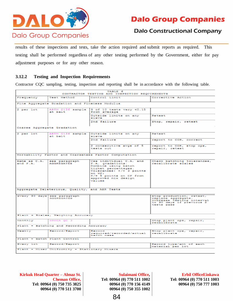
Erbil OfficeEinkawa
Tel: 00964 (0) 770 511 1003
00964 (0) 750 777 1003
Sulaimani Office,
Tel: 00964 (0) 770 511 1002
00964 (0) 770 156 4149
00964 (0) 750 355 1002
Kirkuk Head Quarter – Almaz St.
Cheman Office,
Tel: 00964 (0) 750 735 3825
00964 (0) 770 511 3700
results of these inspections and tests, take the action required and submit reports as required. This
testing shall be performed regardless of any other testing performed by the Government, either for pay
adjustment purposes or for any other reason.
3.12.2 Testing and Inspection Requirements
Contractor CQC sampling, testing, inspection and reporting shall be in accordance with the following table.
84

Erbil OfficeEinkawa
Tel: 00964 (0) 770 511 1003
00964 (0) 750 777 1003
Sulaimani Office,
Tel: 00964 (0) 770 511 1002
00964 (0) 770 156 4149
00964 (0) 750 355 1002
Kirkuk Head Quarter – Almaz St.
Cheman Office,
Tel: 00964 (0) 750 735 3825
00964 (0) 770 511 3700
85

Erbil OfficeEinkawa
Tel: 00964 (0) 770 511 1003
00964 (0) 750 777 1003
Sulaimani Office,
Tel: 00964 (0) 770 511 1002
00964 (0) 770 156 4149
00964 (0) 750 355 1002
Kirkuk Head Quarter – Almaz St.
Cheman Office,
Tel: 00964 (0) 750 735 3825
00964 (0) 770 511 3700
86
Erbil OfficeEinkawa
Tel: 00964 (0) 770 511 1003
00964 (0) 750 777 1003
Sulaimani Office,
Tel: 00964 (0) 770 511 1002
00964 (0) 770 156 4149
00964 (0) 750 355 1002
Kirkuk Head Quarter – Almaz St.
Cheman Office,
Tel: 00964 (0) 750 735 3825
00964 (0) 770 511 3700
3.12.3 Concrete Strength Testing for Contractor CQC
Contractor Quality Control operations for concrete strength shall consist of the following steps:
3.12.4 Reports
All results of tests or inspections conducted shall be reported informally as they are completed and in
writing daily. Prepare a weekly report for the updating of control charts covering the entire period
from the start of the construction season through the current week. During periods of cold-weather
protection, make daily reports of pertinent temperatures. These requirements do not relieve the
Contractor of the obligation to report certain failures immediately as required in preceding paragraphs.
Such reports of failures and the action taken shall be confirmed in writing in the routine reports.
The Contracting Officer has the right to examine all Contractor quality control records.
-- End of Section
87

Erbil OfficeEinkawa
Tel: 00964 (0) 770 511 1003
00964 (0) 750 777 1003
Sulaimani Office,
Tel: 00964 (0) 770 511 1002
00964 (0) 770 156 4149
00964 (0) 750 355 1002
Kirkuk Head Quarter – Almaz St.
Cheman Office,
Tel: 00964 (0) 750 735 3825
00964 (0) 770 511 3700
CONCRETE ROAD PAVEMENT
by
WIRTGEN SP500 PAVER
Execution Plan
Prepared By: Dalo Group Engineering
Reviewed By :- Eng. Hamno Aziz
Approved By :- Eng. Hamno Aziz
88

Erbil OfficeEinkawa
Tel: 00964 (0) 770 511 1003
00964 (0) 750 777 1003
Sulaimani Office,
Tel: 00964 (0) 770 511 1002
00964 (0) 770 156 4149
00964 (0) 750 355 1002
Kirkuk Head Quarter – Almaz St.
Cheman Office,
Tel: 00964 (0) 750 735 3825
00964 (0) 770 511 3700
CONCRETE ROAD PAVEMENT by WIRTGEN SP500 PAVER
MATERIAL :
1. Concrete shall have a flexural strength not less than 4.2Mpa (42kg/cm2) standard specification (flexural
and compressive strength test are required using Testing Beams (15x15x60)cm for flexural tests and
standard cubes for compressive strength tests).
2. Dowels must be used and the spacing is according to the design drawings, and the dowels must be
epoxy painted using “Steel Standard: STM A615 / 615M / Epoxy Paint Standard: ASTM A775 /
775mm”.
3. Superplasticizer concrete admixture: ASTM C 494 Type F / stenmix Super 200” and ” Air-entraining
concrete admixture: ASTM C260 / stenmix Air”, for hot weather concrete “Retarding Concrete
Admixture: ASTM C 494 Type B / stenmix Retarder” must be used, and for pouring concrete in cold
weather “Accelerating Concrete Admixture: ASTM C494-81 Type C / stenmix antifreeze” must be
used.
4. The curing of this concrete must be done using “Concrete Curing Compound: ASTM C309 Type II and
CRD C 300 / stencur White”.
5. The item includes constructing of the expansion joints, contraction and construction joint according to
the drawing and as directed by the Supervising engineer. All joints must be sealed using “Joint Sealant:
EN 14188-2 2K StenSeal” and according to the drawings.
6. If there is any deficiency in the finished surface of the concrete it must be repaired and brushed to be
rough and consistent with texture of the surrounding concrete, “Concrete Repair Materials: ASTM
C881 - StenCare 2EP 310 / StenCare 2EP 311/230 StenCare 2EP” must be used for these repairing.
89

Erbil OfficeEinkawa
Tel: 00964 (0) 770 511 1003
00964 (0) 750 777 1003
Sulaimani Office,
Tel: 00964 (0) 770 511 1002
00964 (0) 770 156 4149
00964 (0) 750 355 1002
Kirkuk Head Quarter – Almaz St.
Cheman Office,
Tel: 00964 (0) 750 735 3825
00964 (0) 770 511 3700
METHODOLOGY :
1. Steel fixed forms of appr. 3 meters each with dowelbar holes shall be placed at both sides of the lane to
be poured. The height of the forms shall be adjusted to 2-3 mm lower than the approved concrete level.
2. Fixed forms shall be aligned as per the approved joint plan.
3. Dowelbars shall be placed into the holes of the fixed forms and secured tightly to these forms.
90

Erbil OfficeEinkawa
Tel: 00964 (0) 770 511 1003
00964 (0) 750 777 1003
Sulaimani Office,
Tel: 00964 (0) 770 511 1002
00964 (0) 770 156 4149
00964 (0) 750 355 1002
Kirkuk Head Quarter – Almaz St.
Cheman Office,
Tel: 00964 (0) 750 735 3825
00964 (0) 770 511 3700
4. Offset wire line of the slipform paver shall be adjusted to the approved level of the concrete and the
slipform paver shall have the elevation signal from this line.
5. Slipform paving shall be performed over the fixed forms at the approved level and approved alignment.
Due to the vibration of the paver appr. 2 mm of this concrete portion shall be composed of fines.
6. Concrete shall be transported with dump trucks. At windy nights, special care shall be taken to prevent
moisture loss of concrete.
7. Concrete shall be dumped in front of slipform paver and shall be spread utilizing a back-hoe loader.
91

Erbil OfficeEinkawa
Tel: 00964 (0) 770 511 1003
00964 (0) 750 777 1003
Sulaimani Office,
Tel: 00964 (0) 770 511 1002
00964 (0) 770 156 4149
00964 (0) 750 355 1002
Kirkuk Head Quarter – Almaz St.
Cheman Office,
Tel: 00964 (0) 750 735 3825
00964 (0) 770 511 3700
8. Slipform paver shall be operated continuously at a speed of minimum 0.6 m per minute to prevent any
possible cold joint in concrete. The floating pan at the back shall operate at such a speed not to cause
accumulation of concrete paste at two ends of lane. This speed shall be adjusted depending on the
amount of paste coming out from oscillating beam.
9. The edge correction and the finishing of the concrete shall be done as per SECTION 32 13 11 of the
RFP. Minimum hand finishing operation shall be done. Straightedges of 4 meters length shall be used
for eliminating irregularities and score marks. Long handled bullfloats shall be used very sparingly. The
surface of the concrete will be at the required and approved elevation. Extreme care shall be taken to
prevent over finishing joints and edges. At the edges of the expansion joints, joint faces shall be
rounded with an edger at a radius of 3 mm.
92

Erbil OfficeEinkawa
Tel: 00964 (0) 770 511 1003
00964 (0) 750 777 1003
Sulaimani Office,
Tel: 00964 (0) 770 511 1002
00964 (0) 770 156 4149
00964 (0) 750 355 1002
Kirkuk Head Quarter – Almaz St.
Cheman Office,
Tel: 00964 (0) 750 735 3825
00964 (0) 770 511 3700
10. All concrete pavements shall have a broom texture. The scoring of the surface shall be as uniform as
possible. Brooms shall be washed thoroughly and frequently. Warn or damaged brooms shall not be
used.
11. Edges will be finished after brooming with an edger with a radius of 3 mm. Tool marks shall be
eliminated by brooming.
12. A uniform coating of a membrane forming curing will follow immediately after all hand works is
finished. Burlapping or polyethylene sheets or similar protection means may be used to protect the
concrete against rain and exposure of direct sunlight after curing membrane is applied the concrete is
hard enough to walk over.
13. Forms shall remain in place at least 10 hours after the concrete has been placed. No injuring of the
edges of the concrete will be allowed when removing the forms.
14. Contraction joints shall be sawed as soon as possible after placing the concrete. It shall be noted that
the concrete is hard enough not to have any marring on the edges of the joints when sawing.
93

Erbil OfficeEinkawa
Tel: 00964 (0) 770 511 1003
00964 (0) 750 777 1003
Sulaimani Office,
Tel: 00964 (0) 770 511 1002
00964 (0) 770 156 4149
00964 (0) 750 355 1002
Kirkuk Head Quarter – Almaz St.
Cheman Office,
Tel: 00964 (0) 750 735 3825
00964 (0) 770 511 3700
OPERATION :
Any concrete pavement work should require a 24 hour operation. A sequence of formwork - concrete
pouring – joint cutting – joint filling shall be repeated on daily routine. To perform this particular job, a
sequence of pilot lanes and fill-in lanes shall be considered. The time interval between pilot lanes and fill-in
lanes shall depend on how soon the required flexural strength will be achieved.
POSSIBLE SCENARIOS :
Actions to be taken are listed below in corresponding cases:
No. Description of case Action
1. Concrete delivery stoppage The location of the first contraction joint shall be determined. Steel
forms shall be installed in this location and pavement shall be
completed up to this first possible contraction joint.
2. Concrete delivery interruption Concrete ready on trucks shall be used at minimum operation speed
of paver. If concrete delivery could not start at least in 15 minutes
after this amount of concrete is used, action #1 shall be taken.
3. Rain only damaging surface
texture
Damaged surfaces shall be textured again and protected by being
covered with a polyethylene sheet.
4. Heavy rain Concrete trucks and fresh concrete surfaces shall be covered. If rain
is so strong that the pavement operation cannot be handled, action #1
shall be taken.
5. Strong wind Moisture loss of fresh concrete shall be prevented by covering
concrete trucks. Time interval between paving and texturing&curing
shall be adjusted to be very short.
94

Erbil OfficeEinkawa
Tel: 00964 (0) 770 511 1003
00964 (0) 750 777 1003
Sulaimani Office,
Tel: 00964 (0) 770 511 1002
00964 (0) 770 156 4149
00964 (0) 750 355 1002
Kirkuk Head Quarter – Almaz St.
Cheman Office,
Tel: 00964 (0) 750 735 3825
00964 (0) 770 511 3700
CONCRETE ROAD PAVEMENT METHOD STATEMENT
1. INTRODUCTION
Concrete pavement at road projects is being preferred to provide a long-lasting road surface
requiring less maintenance costs throughout its service life. This document summarizes
means and methods to be used at paving a concrete road. Most recent technology has been
chosen to ensure durability, driving comfort and low maintenance cost.
2. MATERIAL
Concrete pavements are designed to resist repeated loadings throughout the design service
life. Main load considered is the vertical wheel load of the vehicle having largest load on its
any wheel to be expected to move on the pavement. Concrete mix has to be designed
considering characteristics of the designed underlying course (Crushed Aggregate Base
Course, Stabilized Base Course etc.) and the vertical load.
More importantly, pavements have to be designed to transfer the vertical load on one slab to
the adjacent slab. To provide this, dowel bars are utilized. (Fig. 01)
Fig. 01. Load transfer mechanism by dowels Dowel bars shall be used at each transverse contraction joint. (Pic. 01.) More often steel
dowels are used at pavement projects. However, recently GFRP (Glass fiber reinforced
polymer) are also being manufactured to be used at pavements. (Pic. 02). DALO shall submit
both dowel types for approval.

Erbil OfficeEinkawa
Tel: 00964 (0) 770 511 1003
00964 (0) 750 777 1003
Sulaimani Office,
Tel: 00964 (0) 770 511 1002
00964 (0) 770 156 4149
00964 (0) 750 355 1002
Kirkuk Head Quarter – Almaz St.
Cheman Office,
Tel: 00964 (0) 750 735 3825
00964 (0) 770 511 3700
Pic. 01. Steel dowels at transverse contraction joint Pic. 02. GFRP dowels at transverse contraction joint
Other supportive materials to be used at concrete pavement project are as follows:
Curing Compound ASTM C309 Type II and CRD C 300
StenCure White
Compressible Joint Filler ASTM -D. 1751-83
Joint Sealant Type M, Grade P, Class 25, Use T according to ASTM C920 Stenseal 2K
3. EQUIPMENT
Main equipment to be used to place and finish concrete is the slip-form paver, Wirtgen
SP500 and/or SP1600 and their attachments. (Pic. 03. and 04.)

Erbil OfficeEinkawa
Tel: 00964 (0) 770 511 1003
00964 (0) 750 777 1003
Sulaimani Office,
Tel: 00964 (0) 770 511 1002
00964 (0) 770 156 4149
00964 (0) 750 355 1002
Kirkuk Head Quarter – Almaz St.
Cheman Office,
Tel: 00964 (0) 750 735 3825
00964 (0) 770 511 3700
Pic. 03. Wirtgen SP500 Slipform Paver
Pic. 04. Wirtgen SP1600 Slipform Paver
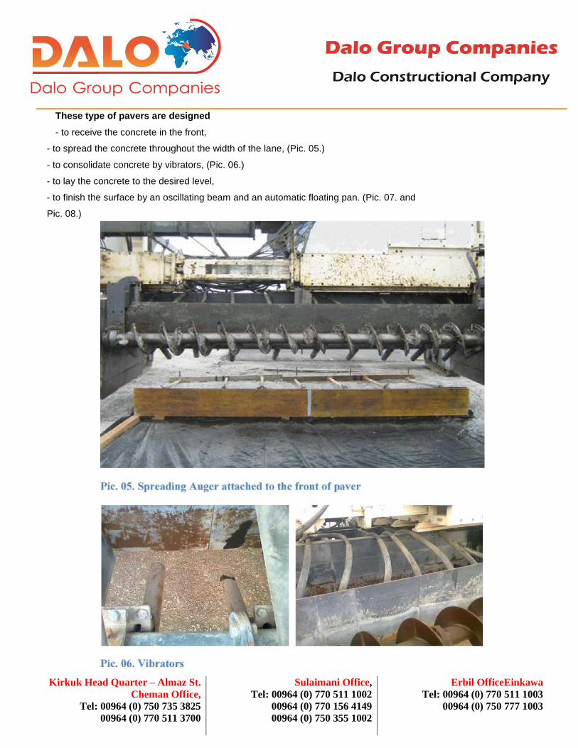
Erbil OfficeEinkawa
Tel: 00964 (0) 770 511 1003
00964 (0) 750 777 1003
Sulaimani Office,
Tel: 00964 (0) 770 511 1002
00964 (0) 770 156 4149
00964 (0) 750 355 1002
Kirkuk Head Quarter – Almaz St.
Cheman Office,
Tel: 00964 (0) 750 735 3825
00964 (0) 770 511 3700
These type of pavers are designed
- to receive the concrete in the front,
- to spread the concrete throughout the width of the lane, (Pic. 05.)
- to consolidate concrete by vibrators, (Pic. 06.)
- to lay the concrete to the desired level,
- to finish the surface by an oscillating beam and an automatic floating pan. (Pic. 07. and
Pic. 08.)

Erbil OfficeEinkawa
Tel: 00964 (0) 770 511 1003
00964 (0) 750 777 1003
Sulaimani Office,
Tel: 00964 (0) 770 511 1002
00964 (0) 770 156 4149
00964 (0) 750 355 1002
Kirkuk Head Quarter – Almaz St.
Cheman Office,
Tel: 00964 (0) 750 735 3825
00964 (0) 770 511 3700
Some paver are also equipped with automatic dowel bar inserters to place middle tie bars
and transverse dowel bars into the fresh concrete as the paver is moving. Wirtgen SP1600 is
one of those paver models able to insert dowels. (Pic. 09.a-b)

Erbil OfficeEinkawa
Tel: 00964 (0) 770 511 1003
00964 (0) 750 777 1003
Sulaimani Office,
Tel: 00964 (0) 770 511 1002
00964 (0) 770 156 4149
00964 (0) 750 355 1002
Kirkuk Head Quarter – Almaz St.
Cheman Office,
Tel: 00964 (0) 750 735 3825
00964 (0) 770 511 3700
Pic. 09.c. Transverse Dowel Bar Inserter

Erbil OfficeEinkawa
Tel: 00964 (0) 770 511 1003
00964 (0) 750 777 1003
Sulaimani Office,
Tel: 00964 (0) 770 511 1002
00964 (0) 770 156 4149
00964 (0) 750 355 1002
Kirkuk Head Quarter – Almaz St.
Cheman Office,
Tel: 00964 (0) 750 735 3825
00964 (0) 770 511 3700
At this project DALO may use one of these pavers.
Some other assisting equipment such as a rubber tire backhoe loader, a work bridge shall
also be utilized during pavement operation. A rubber tire backhoe loader to spread the
concrete in front of the paver,
4. PRELIMINARY WORKS
4.1. Surveying
According to the joint layout plan, all transverse joints shall be marked onto the base course.
The surveyor will install two nails lines, on ground, which will give information to the
pavement team about the project leveling and steering. The nails must be placed 1.00/1.50m
distance parallel to the concrete level. This allows the pavement team to confirm the project
elevations when required during pavement operation. Before starting paving concrete two
stringlines at both sides of the lane shall be installed parallel to the finishing level of
concrete. The guiding line at one side of the paver shall also serve to direct the steering of
the paver.
4.2. Installing Dowels
Option 1. Wirtgen SP 500
Transvers dowel shall have been installed on plastic or steel chairs. (Pic. 01 and 02). Tie bars
shall have been installed into the holes of steel forms (shall be described in detail later).
Option 2. Wirtgen SP1600 with Dowel Bar Inserter
Both transvers dowels and tie bars shall have been loaded onto the paver. Pavement team
shall load them to the dowel inserters during pavement operation.
At both options, expansion dowel shall have been installed onto an assembly which shall be
placed during paving operation. This assembly shall consist of a temporary form with
compressible joint filler placed

Erbil OfficeEinkawa
Tel: 00964 (0) 770 511 1003
00964 (0) 750 777 1003
Sulaimani Office,
Tel: 00964 (0) 770 511 1002
00964 (0) 770 156 4149
00964 (0) 750 355 1002
Kirkuk Head Quarter – Almaz St.
Cheman Office,
Tel: 00964 (0) 750 735 3825
00964 (0) 770 511 3700
4.3. Installing Steel Forms
This paragraph is only valid if Wirtgen SP500 is chosen for paving.
Since Wirtgen SP500 can pave upto 6 m, 12 m wide concrete road shall be paved in 2 lanes.
An hybrid method of slipform and fixed-form shall be used. Steel fixed forms of appr. 3
meters each with dowelbar holes and fixation system shall be placed on the center line of the
road. Tie bars shall be installed into the holes of steel forms. (Pic. 10).
Pic. 10. Fixed form with tie bars installed.
4.4. Other Preparations
Curing compound and burlap (or other synthetic covers) adequate for a day operation shall
be located along the lane. Expansion dowel assemblies shall be located at each expansion
joint lines, outside of the lane (Fig. 02).

Erbil OfficeEinkawa
Tel: 00964 (0) 770 511 1003
00964 (0) 750 777 1003
Sulaimani Office,
Tel: 00964 (0) 770 511 1002
00964 (0) 770 156 4149
00964 (0) 750 355 1002
Kirkuk Head Quarter – Almaz St.
Cheman Office,
Tel: 00964 (0) 750 735 3825
00964 (0) 770 511 3700
Fig. 02. Expansion Joint Assembly
Expansion joint assembly shall consist of double steel sheets 20 mm apart from each other
and the compressible joint filler in-between. Steel sheet shall have U-shaped openings
allowing installation of dowels and removal of the steel sheets when the concrete is hard
enough.
5. OPERATION
Concrete paving operation requires a very well organized sequence of each step. Slipform
pavers are preferred to move at constant speed without stopping. To provide this;
• Minimum 8 dump truck shall be ready for operation.
• Two batch plants shall be installed by DALO for this project. They will be located at 10th
and 20th km of the road as close as possible.
• Depending on the distance from both batch plants, closer shall govern the day operation,
other one shall support the operation.

Erbil OfficeEinkawa
Tel: 00964 (0) 770 511 1003
00964 (0) 750 777 1003
Sulaimani Office,
Tel: 00964 (0) 770 511 1002
00964 (0) 770 156 4149
00964 (0) 750 355 1002
Kirkuk Head Quarter – Almaz St.
Cheman Office,
Tel: 00964 (0) 750 735 3825
00964 (0) 770 511 3700
5.1. Transportation of Concrete
Concrete shall be transported with dump trucks from the batch plant and shall be dumped
onto ground in front of the paver. A rubber tired excavator shall be ready to spread the
concrete dumped from the truck. (Pic. 11). Dump trucks shall be washed at batch plant after
each travel so that no concrete hardens on the surface of the truck. Maximum travel time of
each truck shall be 20 minutes.
Pic. 11. Truck dumping concrete and excavator ready to spread

Erbil OfficeEinkawa
Tel: 00964 (0) 770 511 1003
00964 (0) 750 777 1003
Sulaimani Office,
Tel: 00964 (0) 770 511 1002
00964 (0) 770 156 4149
00964 (0) 750 355 1002
Kirkuk Head Quarter – Almaz St.
Cheman Office,
Tel: 00964 (0) 750 735 3825
00964 (0) 770 511 3700
5.2. Paving
Slipform paver shall be located at the beginning of the lane and the height of the mold shall be adjusted roughly to 30 cm.
Levelling sensors shall be placed onto the guide line. The paver shall be passed to automatic control and the height of the
mold shall be adjusted accurately by raising or lowering the sensor arms. Steering sensors shall also be adjusted
providing that the side forms of the paver shall always follow the edge line of the road. When all automatic levelling and
steering have been adjusted, the paver shall be raised by a known height (by lowering sensor arms by a known number of
cycles) and the paver shall be moved 1-2 m back. This allows the excavator to spread the first load of concrete back to
the beginning of the lane. When the beginning is filled with concrete the paver shall be moved
again to its original position, lowered again and paving shall start. An adjustable metering gate in front of the paver allows
the operator to adjust the height of the concrete before vibration. After that attachment vibrators are consolidating the
concrete. The heavy and very rigid mold provides forming the concrete to desired width and level. An oscillating beam
after the mold is doing screeding of the concrete surface all along the width of the lane and producing finer material
allowing the state-of-art design Supersmoother to finish the concrete surface at the end. (Fig. 03).
Fig. 03. Wirtgen SP 1600

Erbil OfficeEinkawa
Tel: 00964 (0) 770 511 1003
00964 (0) 750 777 1003
Sulaimani Office,
Tel: 00964 (0) 770 511 1002
00964 (0) 770 156 4149
00964 (0) 750 355 1002
Kirkuk Head Quarter – Almaz St.
Cheman Office,
Tel: 00964 (0) 750 735 3825
00964 (0) 770 511 3700
When Wirtgen SP500 is used, one side of the 6 m lane shall be slipformed and the other side with dowels shall be fix-
formed. Transverse dowels shall have been placed on preassembled chairs at every 4.5 m. Therefore dump trucks shall
empty their loads from one or other side of the lane.
With Wirtgen SP1600 the whole width of 12 m can be paved at one pass and both sides shall be slipformed. Dowel Bar
Inserter shall work between the mold and the oscillating beam. Minimum amount of handfinishing shall be used after
supersmoother. Only the edges shall be finished by hand. A work bridge will be used behind the machine to allow any
repair that might occur. This platform will be placed behind, moved by workers and will allow crossing over the just casted
slab. Manual repair will be use for finishing whenever necessary and executed as soon as possible.
After the finishing is smooth, straight and leveled, the slab will be broom at the desire finishing look. (Pic. 12).
Pic. 12. Broom Finishing

Erbil OfficeEinkawa
Tel: 00964 (0) 770 511 1003
00964 (0) 750 777 1003
Sulaimani Office,
Tel: 00964 (0) 770 511 1002
00964 (0) 770 156 4149
00964 (0) 750 355 1002
Kirkuk Head Quarter – Almaz St.
Cheman Office,
Tel: 00964 (0) 750 735 3825
00964 (0) 770 511 3700
5.3. Curing
After achieve the final brooming a uniform coating of curing compound will be spread evenly by a sprayer. The work
bridge shall be use if necessary to reach all width of slab. After the concrete is hard enough to walk over, a Geotextile can
be placed over the slab to avoid direct sunlight. (Pic. 13). Use of water is recommendable to keep humidity and decrease
temperature, especially in very hot days. The geotextile cover shall be kept wet for at least 5 days.
Pic. 13. Laying geotextile to prevent evaporation
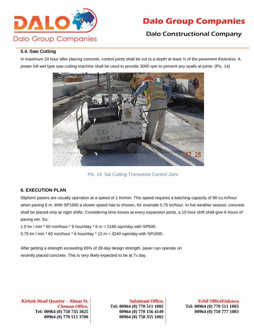
Erbil OfficeEinkawa
Tel: 00964 (0) 770 511 1003
00964 (0) 750 777 1003
Sulaimani Office,
Tel: 00964 (0) 770 511 1002
00964 (0) 770 156 4149
00964 (0) 750 355 1002
Kirkuk Head Quarter – Almaz St.
Cheman Office,
Tel: 00964 (0) 750 735 3825
00964 (0) 770 511 3700
5.4. Saw Cutting
In maximum 24 hour after placing concrete, control joints shall be cut to a depth at least ¼ of the pavement thickness. A
power full wet type saw cutting machine shall be used to provide 3000 rpm to prevent any spalls at joints. (Pic. 14)
Pic. 14. Sat Cutting Transverse Control Joint
6. EXECUTION PLAN
Slipform pavers are usually operation at a speed of 1 lm/min. This speed requires a batching capacity of 90 cu.m/hour
when paving 6 m. With SP1600 a slower speed has to chosen, for example 0.75 lm/hour. In hot weather season, concrete
shall be placed only at night shifts. Considering time losses at every expansion joints, a 10 hour shift shall give 6 hours of
paving net. So;
1.0 lm / min * 60 min/hour * 6 hour/day * 6 m = 2160 sqm/day with SP500.
0.75 lm / min * 60 min/hour * 6 hour/day * 12 m = 3240 sqm/day with SP1600.
After getting a strength exceeding 65% of 28-day design strength, paver can operate on
recently placed concrete. This is very likely expected to be at 7th day.

Erbil OfficeEinkawa
Tel: 00964 (0) 770 511 1003
00964 (0) 750 777 1003
Sulaimani Office,
Tel: 00964 (0) 770 511 1002
00964 (0) 770 156 4149
00964 (0) 750 355 1002
Kirkuk Head Quarter – Almaz St.
Cheman Office,
Tel: 00964 (0) 750 735 3825
00964 (0) 770 511 3700
7. QUALITY CONTROL
A quality pavement requires keeping every stage of operation under control. It starts at
stockpile of sand and gravel, and ends when the joints are sealed.
Below is a check list from start to end:
• Do not let crushed stone overheated under the sunlight. To prevent overheating, either
keep it under a shed or spread and wet the daily amount of crushed stone.
• Keep the temperature of cement under 600 C.
• When paving under sunlight, cover concrete trucks with a tent to prevent moisture loss.
• Keep the temperature of concrete under 320C.
• Keep the paver moving at a constant speed as possible. If stopping required for any
reason, minimize the number of stops.
• Keep people away from the guiding line.
• Keep people other than pavement team away from job site.
• Always check the level of placed concrete to be able to notice any error as earliest as
possible.
• Finish brooming as earliest as possible. This is when the broom does not remove en
stone from the surface.
• Spray curing compound as earliest as possible. This is when the sprayed curing
compound does not flow down or bleed from the surface.

Erbil OfficeEinkawa
Tel: 00964 (0) 770 511 1003
00964 (0) 750 777 1003
Sulaimani Office,
Tel: 00964 (0) 770 511 1002
00964 (0) 770 156 4149
00964 (0) 750 355 1002
Kirkuk Head Quarter – Almaz St.
Cheman Office,
Tel: 00964 (0) 750 735 3825
00964 (0) 770 511 3700
CONCRETE ROAD PAVEMENT
by
WIRTGEN SP500 PAVER
Chemical treatments Material
Prepared By: Dalo Group Engineering
Reviewed By :- Eng. Hamno Aziz
Approved By :- Eng. Hamno Aziz
95

Erbil OfficeEinkawa
Tel: 00964 (0) 770 511 1003
00964 (0) 750 777 1003
Sulaimani Office,
Tel: 00964 (0) 770 511 1002
00964 (0) 770 156 4149
00964 (0) 750 355 1002
Kirkuk Head Quarter – Almaz St.
Cheman Office,
Tel: 00964 (0) 750 735 3825
00964 (0) 770 511 3700
Chemical treatments Material
No. Materials Product By
1 Expansion Join filler / TYPE II STENKIM
2 STENAST®S / Silane Based Surface Conditioner STENKIM
3 StenCare 2EP230 / Cold Applied Epoxy Based Repairing And
Coating Materials STENKIM
4 StenCare 2EP231/ Cold Applied, Epoxy Based, Repair and Coating
Material STENKIM
5 StenCare 2EP310 / Epoxy Based Self Leveling Repair and Coating
Material STENKIM
6 StenCare 2EP311 / Epoxy Based Thixotropic Repair
and Coating Material STENKIM
7 StenCare 3EP-FLEX / Epoksi Esaslı Esnekleştirilmiş
Tamir ve Kaplama Malzemesi STENKIM
8 StenCoat CR-Y / Alkyd Based Road Marking Paint STENKIM
9 StenCure / Water Retentive Paraffinic Emulsion STENKIM
10 Stenkim AER / Air Entraining Additive For Concrete STENKIM
11 Stenkim Dowel / Bar STENKIM
12 StenMix SUPA200 / High Range Water Reducer / Super
Plasticizer STENKIM
13 StenSeal 2K / Jet Fuel Resistant, Cold Applied,
Polyurethane Based, Self Leveling Type Joint Sealant STENKIM
Note :- Specification for All above Materials Attached below
96

97

StenAst® S
1. Product ProfileStenAst® S, is a single component, silane based surface conditioner, prepared for all Stenkim® brand polymer based surface coating materials, top coats and joint sealants.
StenAst® S is available in 2.5 kg packages.
2. UsesStenAst® S is a single component, silane based surface conditioner, prepared for polyurethane materials such as StenFloor®, StenCoat®, StenSeal®, StenSport®, StenCare®
to be applied especially on concrete, wooden, fiberglass surfaces. Unlike the film forming primers, it forms a few molecules thick layer. It reacts at one end of with the application surface and at the other end with the material and chemically strengthens adhesion. Therefore it ensures adhesion without forming a third layer between the surface and the material.
StenAst® S is applied by means of brush or roller in one or two layers depending on the porosity and texture of the application surface.
StenAst® S is very compatible with newly cut joint applications on concrete pavements. Since it does not stain when smeared outside the joint, it does not change the appearance. Due to short curing time, it allows fast application. It is not recommended in dusty environments and in cases where old joint sealant will be removed and a new one will be applied. In such environments layer forming primers like StenAst® PU provides better results than surface conditioners like StenAst® S.
General Purpose, Single Component, Surface Conditioner
HighlightsStenAst® S
It is silane based and single
component.
It is an excellent surface conditioner
on concrete, wooden and fiberglass
substrates for final coating
applications.
It does not form a film layer in
contrast to polyurethane and epoxy
primers.
It enhances adhesion chemically.
It is very compatible with newly cut
joints.
It does not stain when smeared out of
the joint / application area.
Short application time for the top
coating enables fast work, saves work
force and time.
It can be applied via brush and roller.
It is transparent.
3. Surface PreparationConcrete Surfaces: Surface must be free from loose materials, oil, grease, paint and the concrete must be dry. Contaminants
stuck on the surface must be removed by sandblasting or mechanical abrading. Contaminants penetrated into the concrete must be wiped with chemicals that can
Stenkim Kimyasal Maddeler İth. İhr. Taah. Tic. ve San. Ltd. Şti.Office: Portakal Çiçeği Sok. Ansera İş Merkezi 17/126 Ayrancı/ ANKARA Tel: +90 312 442 2630 Fax: +90 312 442 2615 www.stenkim.com.tr
1/3
98

StenAst® Sdissolve the contaminant and must be cleaned with detergent and water.
Note: Detailed information on surface preparation is provided in “Application Techniques: Surface Preparation” document.
4. Application StenAst® S must not be applied at temperatures below 5ºC. Sufficient amount of StenAst® S is taken to the application container and it is continuously applied on the surface using a brush or roller. It is enough to wet the surface. 15 to 25 m² area can be covered with a liter of StenAst® S depending on the surface texture of the concrete pavement and application conditions.
When used for joints, it must be applied on the joint before the backer rod is placed inside. Otherwise it can damage the backer rod since it contains high amount of solvent. Sufficient ventilation must be provided during applications for the same reasons.
5. Application ToolsBrush and Roller: Rollers and brushes to be used must be of professional quality. Brushes must be made of medium dense natural hair.
6. CleaningMixing and application tools must be cleaned with a solvent right after being used. StenSolver CL can be used for this purpose.
7. Warnings• StenAst® S does not leave any marks when
cured; it does not form a visible film layer like other types of primer. This situation requires the applicators to be careful in identifying the application area.• Since it contains high amount of solvent, it must not be considered for cleaning purposes. Contact with skin must be avoided.
8. SafetyApplicators and supervisors must read Material Safety Data Sheet (MSDS) carefully and observe the considerations written therein. Emptied packages must be handled in compliance with relevant regulations and laws.
9. StorageStorage temperature must be between 5ºC and 30ºC. The packages must not be exposed to direct sunlight. Stored unopened in these conditions, the shelf life is 12 months.
10. Company LiabilityThe information contained in this document is based on site experience of and laboratory tests done by Stenkim® and meant to give general information. It is the purchaser's responsibility to ensure applicability of products to their use. All Stenkim® products are available in specified quality and conditions. The company accepts no liability whatsoever unless the transportation, storage, application conditions and customer use are overseen by Stenkim®. Stenkim® reserves the right to update all information contained in this document without notice.
Stenkim Kimyasal Maddeler İth. İhr. Taah. Tic. ve San. Ltd. Şti.Office: Portakal Çiçeği Sok. Ansera İş Merkezi 17/126 Ayrancı/ ANKARA Tel: +90 312 442 2630 Fax: +90 312 442 2615 www.stenkim.com.tr
2/3
99

StenAst® STechnical DataProperty Result
Base Polymer Silane
Solvent Toluene
Density 0.87±0.05g/ cm3
Application Thickness, at each Layer At nano level
Color Transparent
Minimum Curing Time for Top Layer @230C 15 minutes
Maximum Curing Time for Top Layer @230C 24 hoursStenkim® reserves the right to make changes in the values in this table at any time.
Stenkim Kimyasal Maddeler İth. İhr. Taah. Tic. ve San. Ltd. Şti.Office: Portakal Çiçeği Sok. Ansera İş Merkezi 17/126 Ayrancı/ ANKARA Tel: +90 312 442 2630 Fax: +90 312 442 2615 www.stenkim.com.tr
3/3
100

StenCare® 2EP230
1. Product ProfileStenCare® 2EP230 is a two component, cold applied, chemically curing, epoxy based, self leveling repair material. It has high mechanical resistance, flexibility and adhesion, and is suitable for heavy traffic conditions. It is resistant to organic and inorganic acids and alkalies, oils, fuels and antifreezes and many chemicals. It conforms to ASTM C 881/881 M, Type 3, Grade 1, Class C.
StenCare® 2EP230 is available in 5 kg sets.
2. UsesStenCare® 2EP230 is designed for applications that are subject to movement during or after the application. It can be used for outdoor repairs subject to thermal cycling, for production of epoxy concretes, bonding of aggregates of skid resistant coatings or for any repairs on surfaces subject to traffic or movement. It has excellent adhesion to concrete, metal and wooden surfaces, and provides a stable and durable repair. It is also used as filling or adhesive between two different surfaces. Due to its elasticity, it partially isolates movement of those two surfaces from each other.
Cold Applied, Epoxy Based, Repair and Coating Material
HighlightsStenCare® 2EP230
It is epoxy based.
It is designed for horizontal repairs.
It has high mechanical strength along
with high elasticity.
It is heavy duty.
It is thermally and chemically 100%
compatible with concrete.
It is a long lasting material convenient
to use.
3. Surface PreparationThe surfaces where StenCare® 2EP230 will be applied must be dry, free from contaminants such as oil, grease, sealant remains and loose particles.
Metal surfaces must be cleaned by brush. StenCare® 2EP230 adheres excellent on many surfaces without primer; however primer must be used at places in contact with water and in applications on glass, plastic or rubber.
4. ApplicationStenCare® 2EP230 is a two component
material. Components A and B are packed as sets to be completely mixed. Entire component B is poured on component A and they are mixed manually or by means of a low speed drill until a homogeneous mixture is obtained. Prepared mixture must be used within the pot life and thickened materials must not be thinned and used. Applying the material with sufficient pressure and avoiding air entrapment will improve adhesion.
For bonding skid resistant aggregates, the material should be laid on the surface and the aggregates should be broadcast on it
Stenkim Kimyasal Maddeler İth. İhr. Taah. Tic. ve San. Ltd. Şti.Office: Portakal Çiçeği Sok. Ansera İş Merkezi 17/126 Ayrancı/ ANKARA Tel: +90 312 442 2630 Fax: +90 312 442 2615 www.stenkim.com.tr
StenCare® 2EP230 1/2
101

StenCare® 2EP230without delay.
For dowel bar, tie bar installation, or similar anchorage applications, all installation steps should be completed within pot life of the product.
If complete set of StenCare® 2EP230 will not be used, contents of the container must be weighed and partitioned before mixing. Mix ratio by weight must be maintained during this process, otherwise material properties are affected negatively.
5. CleaningMixing and application tools must be cleaned with an aromatic solvent right after being used. StenSolver CL can be used for this purpose.
6. SafetyApplicators and supervisors must read Material Safety Data Sheet (MSDS) carefully
and observe the considerations written therein. Emptied packages must be handled in compliance with relevant regulations and laws.
7. StorageThe material must be kept in dry indoor storages. Recommended storage temperature is 10 – 30ºC. Stored in these conditions, the shelf life is 12 months.
8. Company LiabilityThe information contained in this document is based on site experience of and laboratory tests done by Stenkim® and meant to give general information. It is the purchaser's responsibility to ensure applicability of products to their use. All Stenkim® products are available in specified quality and conditions. The company accepts no liability whatsoever unless the transportation, storage, application conditions and customer use are overseen by Stenkim®.
Technical DataProperty Method Result
Base Polymer 2 Component Epoxy
Solids Content % 100
Colors Grey
Density (A+B) 1,60 ± 0,1 g/cm3
Durometer Hardness (Shore) ASTM D 2240 D45±5
Bonding Strength ASTM C 882 20±2 MPa
Compressive Modulus ASTM D 695 730 MPa
Thermal Compatibility ASTM C 884 Pass
Elongation at Break ASTM D 638 >%60
Gelling time @30ºC ASTM C 881 30 minutes
Cure Time For Heavy Trafficability @30°C 24 hours
Cure Time For Chemical Resistance @30°C 72 hoursStenkim® reserves the right to make changes in the values in this table at any time.
Stenkim Kimyasal Maddeler İth. İhr. Taah. Tic. ve San. Ltd. Şti.Office: Portakal Çiçeği Sok. Ansera İş Merkezi 17/126 Ayrancı/ ANKARA Tel: +90 312 442 2630 Fax: +90 312 442 2615 www.stenkim.com.tr
StenCare® 2EP230 2/2
102

StenCare® 2EP231
1. Product ProfileStenCare® 2EP231 is a two component, cold applied, chemically curing, epoxy based anchorage and coating material which can be used in sloped, vertical or reverse joints, with high mechanical resistance and adhesion, suitable for heavy traffic conditions. It is resistant to organic and inorganic acids and alkalies, oils, fuels and antifreezes and many chemicals.
It conforms to ASTM C 881/881M Type 3, Grade 3, Class B and Class C.
StenCare® 2EP231 is available in 5 kg sets.
2. UsesStenCare® 2EP231 is designed for application that are subject to movement during or after the application. It can be used for dowel bar installation, bonding of aggregates of skid resistant coatings or for any repairs on surfaces subject to traffic or movement. It can be used for repairs at sloped, vertical and reverse surfaces. It has excellent adhesion to concrete, metal and wooden surfaces, and provides a stable and durable repair. It is also used as filling or adhesive between two different surfaces.
Due to its elasticity, it partially isolates movement
Cold Applied, Epoxy Based, Repair and Coating Material
HighlightsStenCare® 2EP231
It is epoxy based.
It is designed for overhead, vertical
and sloped repairs.
It has high mechanical strength along
with high elasticity.
It is heavy duty.
It is 100% compatible with concrete.
It cures fast, does not delay traffic.
It is a long lasting material convenient
to use.
of those two surfaces from each other.
3. Surface PreparationThe surfaces where StenCare® 2EP231 will be applied must be dry, free from contaminants such as oil, grease, sealant remains and loose particles.
Metal surfaces must be cleaned by brush. StenCare® 2EP231 adheres excellent on many surfaces without primer; however primer must be used at places in contact with water and in applications on glass, plastic or rubber.
4. ApplicationStenCare® 2EP231 is a two component material. Components A and B are packed as sets to be completely mixed. Entire component B is poured on component A and they are mixed manually or by means of a low speed drill until a homogeneous mixture is obtained. Prepared mixture must be used within the pot life and thickened materials must not be thinned and used. Applying the material with sufficient pressure and avoiding air entrapment will improve adhesion. For bonding kid resistant aggregates, the material should be laid on the surface and
Stenkim Kimyasal Maddeler İth. İhr. Taah. Tic. ve San. Ltd. Şti.Office: Portakal Çiçeği Sok. Ansera İş Merkezi 17/126 Ayrancı/ ANKARA Tel: +90 312 442 2630 Fax: +90 312 442 2615 www.stenkim.com.tr
StenCare® 2EP231 1/2
103

StenCare® 2EP231the aggregates should be broadcast on it without delay. For dowel bar, tie bar installation, or similar anchorage applications, all installation steps should be completed within pot life of the product. If complete set of StenCare® 2EP231 will not be used, contents of the container must be weighed and partitioned before mixing. Mix ratio by weight must be maintained during this process, otherwise material properties are affected negatively.
5. CleaningMixing and application tools must be cleaned with an aromatic solvent right after being used. StenSolver CL can be used for this purpose.
6. SafetyApplicators and supervisors must read Material Safety Data Sheet (MSDS) carefully and observe the considerations written therein. Emptied packages must be handled in
compliance with relevant regulations and laws.
7. StorageThe material must be kept in dry indoor storages. Recommended storage temperature is 10 – 30 ºC. Stored unopened in these conditions, the shelf life is 12 months.
8. Company LiabilityThe information contained in this document is based on site experience of and laboratory tests done by Stenkim® and meant to give general information. It is the purchaser's responsibility to ensure applicability of products to their use. All Stenkim® products are available in specified quality and conditions. The company accepts no liability whatsoever unless the transportation, storage, application conditions and customer use are overseen by Stenkim®. Stenkim® reserves the right to update all information contained in this document without notice.
Technical DataProperty Method Result
Base Polymer 2 Component Epoxy
Solids Content % 100
Colors Grey
Density (A+B) 1,66± 0,05 g/cm3
Consistency ASTM C 881 2 mm
Durometer Hardness (Shore) ASTM D 2240 D50±5
Bonding Strength ASTM C 882 17 MPa
Compressive Modulus ASTM D 695 720 MPa
Thermal Compatibility ASTM C 884 Pass
Elongation at Break ASTM D 638 >%45
Gelling Time @15ºC ASTM C 881 30 minutes
Gelling time @20ºC ASTM C 881 15 minutes
Cure Time For Heavy Trafficability @20°C 12 hours
Cure Time For Chemical Resistance 24 hours Stenkim® reserves the right to make changes in the values in this table at any time.
Stenkim Kimyasal Maddeler İth. İhr. Taah. Tic. ve San. Ltd. Şti.Office: Portakal Çiçeği Sok. Ansera İş Merkezi 17/126 Ayrancı/ ANKARA Tel: +90 312 442 2630 Fax: +90 312 442 2615 www.stenkim.com.tr
StenCare® 2EP231 2/2
104

StenCare® 2EP310
1. Product ProfileStenCare® 2EP310 is a heavy duty, solvent-free, pourable grade epoxy repair andcoating material. It has high adhesion andabrasion resistance properties, and it isresistant to chemicals. It is resistant to weakorganic and inorganic acids and alkalies,oils, fuels and antifreezes and manychemicals.
StenCare® 2EP310 conforms to specificationASTM C881/C881 M Grade 2, Type I, IV, V andClass B and Class C.
StenCare® 2EP310 is available in 10 kg sets.
2. UsesStenCare® 2EP310 is used in repairing oldconcrete surfaces, broken slab and jointedges, as adherence promoter between oldconcrete and fresh concrete, for rigidanchorages and dowel bar fixing. It is usedindoors and outdoors, in all kinds of repairwhere high elasticity is not required. It hasexcellent adhesion to concrete, metal andwooden surfaces, and provides a stable anddurable repair.
Epoxy Based Self Leveling Repair and Coating Material
Highlights
StenCare® 2EP310It is epoxy based.
It is heavy duty.
Its curing speed can be adjusted to
weather and job site conditions.
It has high load bearing properties.
It is 100% compatible with concrete.
It is resistant to chemicals.
It is a long lasting material convenientto use.
3. Surface PreparationThe surfaces where StenCare® 2EP310 willbe applied must be dry, free fromcontaminants such as oil, grease, sealantremains and loose particles. Metal surfacesmust be cleaned by brush.
StenCare® 2EP310 adheres excellent onmany surfaces without primer; howeverprimer must be used at places in contactwith water and in applications on glass,plastic or rubber.
4. ApplicationStenCare® 2EP310 is a two componentmaterial. Components A and B are packed as
sets to be completely mixed. Entirecomponent B is poured on component A andthey are mixed manually or by means of alow speed drill until a homogeneous mixtureis obtained. For areas that require earlytrafficability or under cold ambientconditions StenQuick EP may be used tospeed up curing. StenQuick EP should beadded to component B or if container sizedoes not permit that, to the mixture ofcomponents B and A.
Prepared mixture must be used within thepot life and thickened materials must not bethinned and used. Applying the material withsufficient pressure and avoiding airentrapment will improve adhesion. For
Stenkim Kimyasal Maddeler İth. İhr. Taah. Tic. ve San. Ltd. Şti.Office: Portakal Çiçeği Sok. Ansera İş Merkezi 17/126 Ayrancı/ ANKARA Tel: +90 312 442 2630 Fax: +90 312 442 2615 www.stenkim.com.tr
StenCare® 2EP310 1/3
105

StenCare® 2EP310surface coating application, the material shouldbe poured on the substrate and spread with atoothed trowel. Once the material is spread,it should left to self level and cure withouttoo much disturbance. The coated areashould be kept free from vehicle exhaust andflue gases for at least an hour.
For adhesion promotion, fresh concreteshould be placed before the material thathas been applied on to old concrete surfacebecomes tack free. If the material has curedto a tack free state, another coat of thematerial can be applied without removingthe previous coat.
For repairs and anchorage jobs withaggregates, the aggregates should be addedto mixture of A and B components withoutdelay, and all should be mixed for at leasttwo more minutes. The moisture present onaggregate particles may lead to unexpectedchanges in curing time. Inadequately gradedparticles may lead to poor strength andapplication time problems. For thesereasons, either three component StenCare®
3EP should be used instead of StenCare®
2EP310, or adequately graded and driedStenSilica aggregates should be used.
For armature fixing and dowel barinstallation, pot life must be observedclosely. Special attention must be paid toensure no voids are left under the materialduring dowel bar fixing. If complete set ofStenCare® 2EP310 will not be used,contents of the container must be weighedand partitioned before mixing. Mix ratio byweight must be maintained during this
process, otherwise material properties areaffected negatively.
5. CleaningMixing and application tools must be cleanedwith an aromatic solvent right after beingused. StenSolver CL can be used for thispurpose.
6. SafetyApplicators and supervisors must readMaterial Safety Data Sheet (MSDS) carefullyand observe the considerations writtentherein. Emptied packages must be handledin compliance with relevant regulations andlaws.
7. StorageThe material must be kept in dry indoorstorages. Recommended storage temperatureis 10 – 30ºC. Stored in these conditions, theshelf life is 12 months.
8. Company LiabilityThe information contained in this documentis based on site experience of and laboratorytests done by Stenkim® and meant to givegeneral information. It is the purchaser'sresponsibility to ensure applicability ofproducts to their use. All Stenkim® productsare available in specified quality andconditions. The company accepts no liabilitywhatsoever unless the transportation,storage, application conditions and customeruse are overseen by Stenkim®. Stenkim® reserves the right to update allinformation contained in this documentwithout notice.
Stenkim Kimyasal Maddeler İth. İhr. Taah. Tic. ve San. Ltd. Şti.Office: Portakal Çiçeği Sok. Ansera İş Merkezi 17/126 Ayrancı/ ANKARA Tel: +90 312 442 2630 Fax: +90 312 442 2615 www.stenkim.com.tr
StenCare® 2EP310 2/3
106
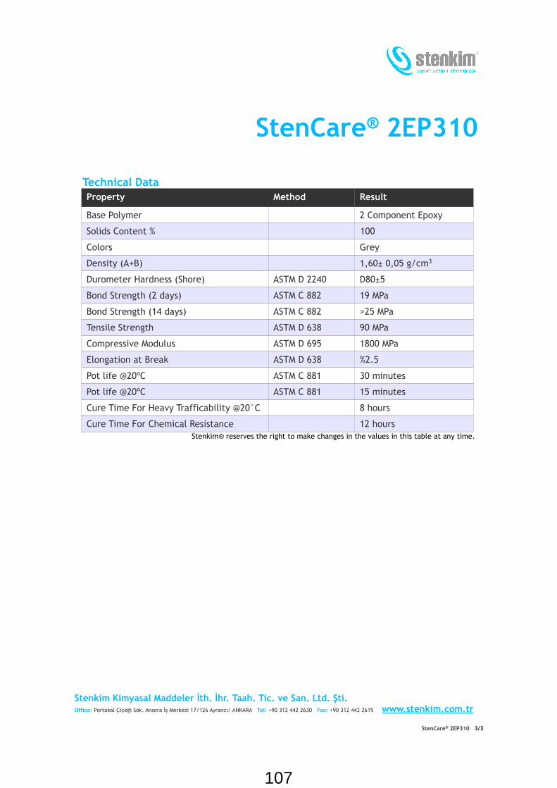
StenCare® 2EP310
Technical DataProperty Method Result
Base Polymer 2 Component Epoxy
Solids Content % 100
Colors Grey
Density (A+B) 1,60± 0,05 g/cm3
Durometer Hardness (Shore) ASTM D 2240 D80±5
Bond Strength (2 days) ASTM C 882 19 MPa
Bond Strength (14 days) ASTM C 882 >25 MPa
Tensile Strength ASTM D 638 90 MPa
Compressive Modulus ASTM D 695 1800 MPa
Elongation at Break ASTM D 638 %2.5
Pot life @20ºC ASTM C 881 30 minutes
Pot life @20ºC ASTM C 881 15 minutes
Cure Time For Heavy Trafficability @20°C 8 hours
Cure Time For Chemical Resistance 12 hours Stenkim® reserves the right to make changes in the values in this table at any time.
Stenkim Kimyasal Maddeler İth. İhr. Taah. Tic. ve San. Ltd. Şti.Office: Portakal Çiçeği Sok. Ansera İş Merkezi 17/126 Ayrancı/ ANKARA Tel: +90 312 442 2630 Fax: +90 312 442 2615 www.stenkim.com.tr
StenCare® 2EP310 3/3
107

StenCare® 2EP311
1. Product ProfileStenCare® 2EP311 is a heavy duty, solvent-free epoxy based, thixotropic grade repair and coating material. It has high adhesion and abrasion resistance properties, and it is resistant to chemicals. It is resistant to weak organic and inorganic acids and alkalies, oils, fuels and antifreezes and many chemicals.
StenCare® 2EP311 conforms to specification ASTM C881/C881 M Grade 3, Type I, IV, V, Class B and Class C.
StenCare® 2EP311 is available in 10 kg sets.
2. UsesStenCare® 2EP311 is used for repairing old concrete surfaces, broken slab and joint edges, for rigid anchorages and dowel bar fixing. It is used indoors and outdoors, in all kinds of repair where high elasticity is not required. It has excellent adhesion to concrete, metal and wooden surfaces, and provides a stable and durable repair.
3. Surface PreparationThe surfaces where StenCare® 2EP311 will be applied must be dry, free from contaminants such as oil, grease, sealant remains and loose particles. Metal surfaces must be cleaned by brush.
Epoxy Based Thixotropic Repair and Coating Material
HighlightsStenCare® 2EP311
It is epoxy based.
It is designed for overhead, vertical
and sloped repairs.
It is heavy duty.
Its curing speed can be adjusted to
weather and job site conditions.
It has high load bearing properties.
It is 100% compatible with concrete.
It is resistant to chemicals.
It is a long lasting material convenient
to use.
StenCare® 2EP311 adheres excellent on many surfaces without primer; however primer must be used at places in contact with water and in applications on glass, plastic or rubber.
4. ApplicationStenCare® 2EP311 is a two component material. Components A and B are packed as sets to be completely mixed. Entire component B is poured on component A and they are mixed manually or by means of a low speed drill until a homogeneous mixture
is obtained. For areas that require early trafficability or under cold ambient conditions StenQuick EP may be used to speed up curing. StenQuick EP should be added to component B or if container size does not permit .that, to the mixture of components B and A.
Prepared mixture must be used within the pot life and thickened materials must not be thinned and used. Applying the material with sufficient pressure and avoiding air entrapment will improve adhesion. In surface
Stenkim Kimyasal Maddeler İth. İhr. Taah. Tic. ve San. Ltd. Şti.Office: Portakal Çiçeği Sok. Ansera İş Merkezi 17/126 Ayrancı/ ANKARA Tel: +90 312 442 2630 Fax: +90 312 442 2615 www.stenkim.com.tr
StenCare® 2EP311 1/3
108

StenCare® 2EP311coating applications the product is applied by a roller. The coated area should be kept free from vehicle exhaust and flue gases for at least an hour.
For repairs and anchorage jobs with aggregates, the aggregates should be added to mixture of A and B components without delay, and all should be mixed for at least two more minutes. The moisture present on aggregate particles may lead to unexpected changes in curing time. Inadequately graded particles may lead to poor strength and application time problems. For these reasons, either three component StenCare® 3EP should be used instead of StenCare® 2EP311, or adequately graded and dried StenSilica aggregates should be used.
For armature fixing and dowel bar installation, pot life must be observed closely. Special attention must be paid to ensure no voids are left under the material during dowel bar fixing. If complete set of StenCare® 2EP311 will not be used, contents of the container must be weighed and partitioned before mixing. Mix ratio by weight must be maintained during this process, otherwise material properties are affected negatively.
5. CleaningMixing and application tools must be cleaned
with an aromatic solvent right after being used. StenSolver CL can be used for this purpose.
6. SafetyApplicators and supervisors must read Material Safety Data Sheet (MSDS) carefully and observe the considerations written therein. Emptied packages must be handled in compliance with relevant regulations and laws.
7. StorageThe material must be kept in dry indoor storages. Recommended storage temperature is 10 – 30ºC. Stored unopened in these conditions, the shelf life is 12 months.
8. Company LiabilityThe information contained in this document is based on site experience of and laboratory tests done by Stenkim® and meant to give general information. It is the purchaser's responsibility to ensure applicability of products to their use. All Stenkim® products are available in specified quality and conditions. The company accepts no liability whatsoever unless the transportation, storage, application conditions and customer use are overseen by Stenkim®. Stenkim® reserves the right to update all information contained in this document without notice.
Stenkim Kimyasal Maddeler İth. İhr. Taah. Tic. ve San. Ltd. Şti.Office: Portakal Çiçeği Sok. Ansera İş Merkezi 17/126 Ayrancı/ ANKARA Tel: +90 312 442 2630 Fax: +90 312 442 2615 www.stenkim.com.tr
StenCare® 2EP311 2/3
109

StenCare® 2EP311
Technical DataProperty Method Result
Base Polymer 2 Component Epoxy
Solids Content % 100
Colors Grey
Density (A+B) 1,60± 0,05 g/cm3
Durometer Hardness (Shore) ASTM D 2240 D80±5
Consistency ASTM C 881 2 mm
Bond Strength (2 days) ASTM C 882 19 MPa
Bond Strength (14 days) ASTM C 882 >25 MPa
Compressive Modulus ASTM D 695 1800 MPa
Elongation at Break ASTM D 638 %2.5
Pot life @20ºC ASTM C 881 30 minutes
Pot life @20ºC ASTM C 881 15 minutes
Cure Time For Heavy Trafficability @20°C 8 hours
Cure Time For Chemical Resistance 12 hours Stenkim® reserves the right to make changes in the values in this table at any time.
Stenkim Kimyasal Maddeler İth. İhr. Taah. Tic. ve San. Ltd. Şti.Office: Portakal Çiçeği Sok. Ansera İş Merkezi 17/126 Ayrancı/ ANKARA Tel: +90 312 442 2630 Fax: +90 312 442 2615 www.stenkim.com.tr
StenCare® 2EP311 3/3
110

StenCare® 3EP-FLEX
1. Ürün TanıtımıStenCare® 3EP-FLEX ağır hizmet tipi, solvent ihtiva etmeyen, akıtılarak uygulanabilen, kaymazlık sağlayan özel boyutlandırılmış katı dolgularla taşıma gücü yüksek bir zemin oluşturan, epoksi esaslı kaplama ve onarım malzemesidir. İki veya üç bileşenli olarak kullanılır. Yüksek yapışma ve aşınma direnci ile kimyasal etkilere dayanım özelliklerine sahiptir. Polimerik karışım, portland çimentosundan yapılmış betonun ısıl genleşmelerine uyum gösterir ve betona çok iyi yapışır. Bağlayıcısı esnek olduğundan, termal ve mekanik hareketlere dirençlidir. Minör hareketlere maruz yerlerde derz gerektirmez. Zayıf organik ve inorganik asit ve alkalilere; yağ, yakıt ve antifirizlere ve birçok kimyasala karşı dayanıklıdır.
StenCare® 3EP-FLEX 15 kg'lık takımlar halinde piyasaya sunulmuştur.
2. Kullanım Yerleri StenCare® 3EP-FLEX eski beton yüzeylerin, kırık ano ve derz kenarlarının ve benzeri yerlerin onarımında kullanılır. Yaya yürüme yollarında, endüstriyel depolama tank sahalarındaki zeminlerde, hava alanı yaya yollarında, park yerlerindeki dönüş ve yavaşlama bölgelerinde ve bu mekanlardaki beton, mozaik, karo, ahşap, metal ve asfalt yüzeylerde kullanım için uygundur.
Epoksi Esaslı EsnekleştirilmişTamir ve Kaplama Malzemesi
AvantajlarStenCare® 3EP-FLEX
Epoksi esaslıdır.
Ağır koşullara dayanıklıdır.
Derz açılmaksızın kullanılabilir
Harekete dirençlidir
Kaygan değildir.
Betonla %100 uyumludur.
Küçük, büyük her türlü beton tamiri
için idealdir.
Kimyasallara karşı dirençlidir.
Uzun ömürlü ve uygulaması kolay bir
malzemedir.
3. Sistem Tasarım ÖzellikleriSistem tasarımı yapılırken mevcut durumun ve uygulamadaki hedefin her yönü ile tanımlanması gerekir. Ağır trafik taşıyan zeminlerdeki onarımlarda derinliğin en az 5cm, orta trafik yükündeki yerlerde en az 3cm, hafif trafik yükündeki yerlerde en az 2cm olması önerilir. Yüzeysel kaplamalarda ise en az 2,5mm kalınlık gereklidir. Kullanılacak agreganın en büyük boyutu minimum uygulama yüksekliğinin yarısını geçmemelidir.
4. Uygulama4.1. Yüzey Hazırlama - GenelYüzeyin doğru ve uygun biçimde hazırlanması büyük öneme sahiptir. Zeminde yağ, kir, asfalt, eski yama malzemesi bırakılmamalıdır. Toz ve gevşek malzemeler temizlenmelidir. Uygulama sırasında çevre ve zemin sıcaklığı 15°C ile 30°C arasında, zemindeki bağıl nem oranı en fazla %75 olmalıdır.
Not: Yüzey hazırlama konusunda ayrıntılı bilgiler “Yüzey Hazırlığı: Kaplama Yapılacak Zeminlerdeki Yüzeyler” belgesinde
Stenkim Kimyasal Maddeler İth. İhr. Taah. Tic. ve San. Ltd. Şti.Ofis: Portakal Çiçeği Sok. Ansera İş Merkezi 17/126 Ayrancı/ ANKARA Tel: +90 312 442 2630 Faks: +90 312 442 2615 www.stenkim.com.tr
StenCare® 3EP-FLEX 1/4
111

StenCare® 3EP-FLEXsunulmaktadır.
4.2. AstarAstar olarak temiz beton zeminlerde ve kapalı alanlarda malzemenin kendisi kullanılabilir. Bu durumda yüzey pürüzlülüğüne bağlı olarak 0,2-0,3kg StenCare® 3EP-FLEX uygulanır. Ancak yapışma gücünü iyice arttırmak üzere önce StenAst® S uygulamak yararlıdır. StenAst® S'in tüketim miktarı yaklaşık 50g/m2' dir. StenAst® S uygulandıktan sonra 30 dakika içinde zemin üst katmanın (StenCare® 3EP-FLEX) uygulanmasına uygun hale gelir. StenCare® 3EP-FLEX uygulandıktan sonra 4 saat kurumaya bırakılır ve henüz bu katman yapışkan haldeyken asıl kaplama uygulanır. Yüzey özelliklerinin gerektirdiği başka tür bir astar kullanılacaksa astarın kullanma talimatına uyulur.
4.3. Serpme Agregalı Kaplama UygulamasıBu yöntem yüzeysel kaplama veya ince yüzey onarımı amacıyla kullanılır. A ve B bileşenleri karıştırıldığında kendiliğinden yayılma özelliğindedir. Bu malzemenin uygulanacağı yüzeyin gerektiği şekilde hazırlanmış olması büyük önem taşır. Böyle bir zemin üzerine kolay, çabuk ve hatasız sonuç veren bir uygulama mümkündür.Karıştırma ve UygulamaÖnce A bileşeni 3-4 dakika karıştırılır. Daha sonra B bileşeni A bileşeninin bulunduğu kutuya katılarak homojen karışım elde edilinceye kadar karıştırılır. Karıştırma işi jiffy tipi mikser ve düşük devirli (300-500 rpm) güçlü bir makine ile yapılır. Kutunun dibinde ve çevresinde karışmamış malzeme kalmamasına dikkat edilir. Karıştırma işleminin uzatılmaması, 2 - 3 dk içinde bitirilmesi ve karıştırılan malzemenin kutusu içinde bekletilmemesi gerekir. Aksi halde sertleşme reaksiyonu ısı veren bir reaksiyon olduğu için kutu içindeki malzeme ısınır ve sertleşme hızı yükselir. Bu durumda kutudaki karışmış malzeme kısa sürede katılaşır ve uygulanmaz hale gelir. Ancak zemine dökülen malzeme zemin tarafından soğutulacağından,
reaksiyon yavaşlar ve uygulama için gerekli zaman kazanılır.
Karışım zemine dökülerek çelik veya plastik gelberi mastarla ve fırça veya 25 - 50 mm' lik (nap) rulo ile 2,0 - 2,5 mm kalınlığında uygulanır.
Hemen sonra 1,5 ile 4 mm aralığında boyutlandırılmış kırma agrega serpilerek istenen yüzey granülasyonu sağlanır. Kullanılan agregalar yüksek sertlikte, aşınmaya dayanıklı malzemelerden seçilmelidir. Bu amaçla StenSilica #8-#9 uygundur. Prizini alan malzemenin üzerindeki serbest agregalar süpürülerek uzaklaştırılır. En üst katmanda kullanılacak agrega büyüklüğü istenen yüzey pürüzlülüğüne göre seçilir. Malzemenin gün ışığına direncini arttırmak için en son kat olarak StenCoat® AntiUV kullanılması tavsiye edilir.
4.4. Agregalı Karışımla Onarım UygulamasıBu yöntem daha çok beton kaplamaların onarımı amacıyla kullanılır. Kendiliğinden yayılma özelliğindeki bu malzemenin karıştırıldıktan sonra uygulanacağı yüzeyin gerektiği şekilde hazırlanmış olması büyük önem taşır. Yukarıda sözü edilen şekilde hazırlanan zemin üzerine kolay, çabuk ve hatasız sonuç veren bir uygulama mümkündür.Karıştırma ve UygulamaBu amaçla yapılacak uygulamada hilti veya betoniyer tipi ağır hizmet harç karıştırıcıların kullanılması gereklidir. Bileşenlerin karıştırılması işlemi aşağıdaki gibi yapılır. A bileşeni miksere alınarak üzerine agrega ilave edilir ve homojen yapı elde edilene kadar 1-2 dakika karıştırılır. Bu karışımın üzerine B bileşeni katılarak 1-2 dakika daha karıştırılır ve beklenilmeksizin uygulama yerine dökülür; önce kabaca yayılır ve ardından mastarla düzlenir. Malzeme prizlenmeden önce isteğe bağlı olarak yüzeye ilave agrega serpiştirilebilir. Prizini alan malzemenin üzerindeki serbest agregalar süpürülerek uzaklaştırılır. Kullanılan agregalar yüksek sertlikte, aşınmaya
Stenkim Kimyasal Maddeler İth. İhr. Taah. Tic. ve San. Ltd. Şti.Ofis: Portakal Çiçeği Sok. Ansera İş Merkezi 17/126 Ayrancı/ ANKARA Tel: +90 312 442 2630 Faks: +90 312 442 2615 www.stenkim.com.tr
StenCare® 3EP-FLEX 2/4
112

StenCare® 3EP-FLEXdayanıklı malzemelerden seçilmelidir. Bu amaçla StenSilica #5-#10 (0,25 – 7 mm) uygundur. Malzemenin gün ışığına direncini arttırmak için en son kat olarak StenCoat®
Anti UV kullanılması tavsiye edilir.
4.5. Uygulama AletleriMikser: Jiffy tipi ve tamburlu (betoniyer veya ağır hizmet harç mikseri). Fırça ve Rulo: Kullanılacak rulo ve fırçalar profesyonel kalitede olmalıdır. Fırçalar orta sıklıkta doğal kıldan yapılmış olmalıdır. Mastar/Mala: Çelikten yapılmış, düz mastarlar, düz ve dişli malalar kullanılır.
5. TemizlikKarıştırma ve uygulama aletleri, işleri bittikten sonra aromatik bir solventle temizlenmelidir. StenSolver EP bu amaçla kullanılabilir.
6. GüvenlikMalzeme Güvenlik Bilgi Formu (MSDS) uygulayıcılar ve denetleyiciler tarafından dikkatle okunmalı ve yazılan hususlara uygun davranılmalıdır. Boşalan ambalajlar konusunda bu husustaki yönetmelik ve yasalara uygun şekilde davranılmalıdır.
7. Malzemenin SaklanmasıMalzemeler sıcaklığı kontrol edilebilen ve 10-30°C'de tutulan depolarda saklanmalı, gün ışığından ve rutubetten korunmalıdır. Malzemeler açık alev ve yangın tehlikesi oluşturabilecek kaynaklardan uzakta tutulmalıdırlar. Bu koşullarda malzeme, açılmamış ambalajında üretim tarihinden itibaren 24 ay süre ile özelliklerini koruyacaktır.
8. Firma SorumluluğuBu dokümandaki veriler genel bilgi verme amacıyla düzenlenmiş olup Stenkim®'in deneyimlerine ve laboratuvar testlerine dayanmaktadır. Uygulama alanındaki yeterliliğe ilişkin karar verme sorumluluğu alıcıya aittir. Stenkim® tüm ürünlerini belirttiği kalite ve koşullarda piyasaya sunar. Ancak alıcının taşıma, saklama, uygulama koşulları ve kullanımı hakkında hiçbir bilgiye sahip olamayacağı için kontrolü dışında yapılan uygulamalara ilişkin herhangi bir garanti vermez. Stenkim® bu dokümandaki tüm verileri haber vermeksizin değiştirme hakkını saklı tutar.
Stenkim Kimyasal Maddeler İth. İhr. Taah. Tic. ve San. Ltd. Şti.Ofis: Portakal Çiçeği Sok. Ansera İş Merkezi 17/126 Ayrancı/ ANKARA Tel: +90 312 442 2630 Faks: +90 312 442 2615 www.stenkim.com.tr
StenCare® 3EP-FLEX 3/4
113
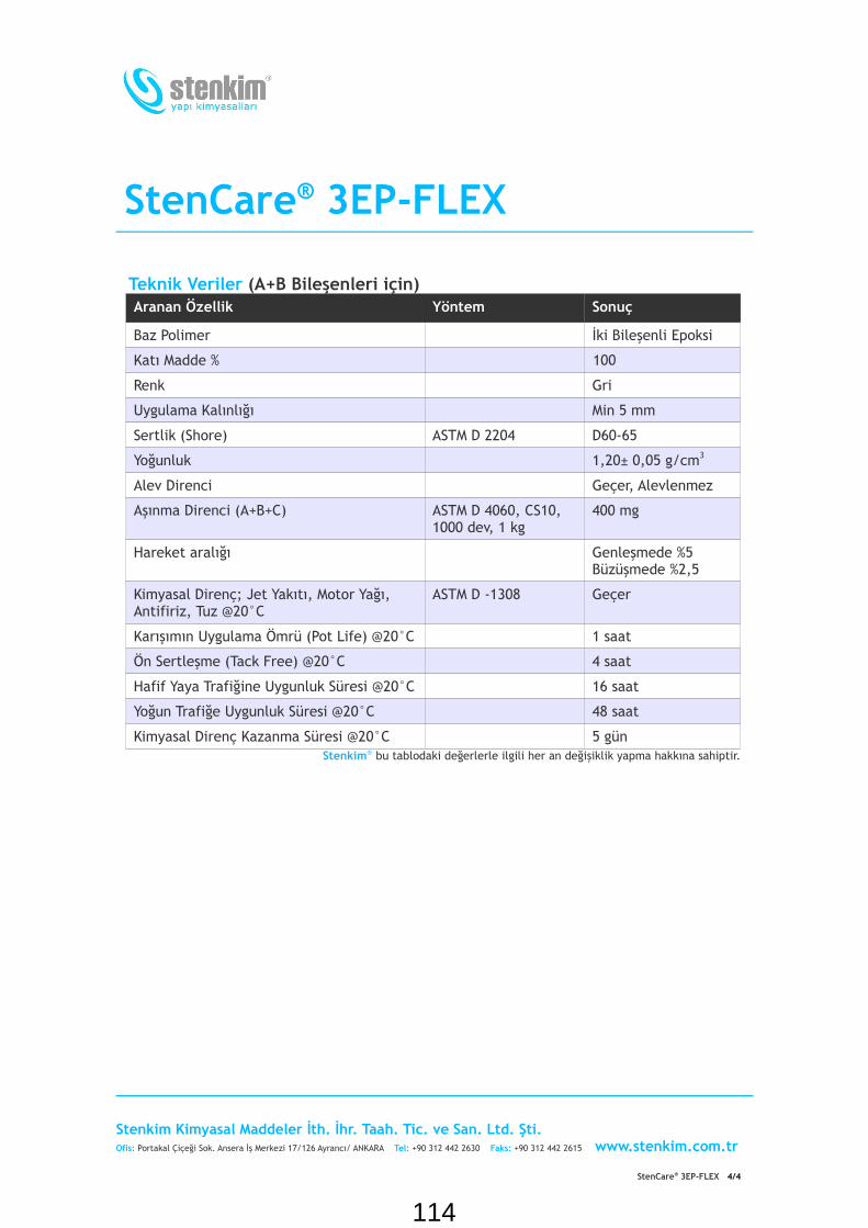
StenCare® 3EP-FLEX
Teknik Veriler (A+B Bileşenleri için)Aranan Özellik Yöntem Sonuç
Baz Polimer İki Bileşenli Epoksi
Katı Madde % 100
Renk Gri
Uygulama Kalınlığı Min 5 mm
Sertlik (Shore) ASTM D 2204 D60-65
Yoğunluk 1,20± 0,05 g/cm3
Alev Direnci Geçer, Alevlenmez
Aşınma Direnci (A+B+C) ASTM D 4060, CS10, 1000 dev, 1 kg
400 mg
Hareket aralığı Genleşmede %5 Büzüşmede %2,5
Kimyasal Direnç; Jet Yakıtı, Motor Yağı, Antifiriz, Tuz @20°C
ASTM D -1308 Geçer
Karışımın Uygulama Ömrü (Pot Life) @20°C 1 saat
Ön Sertleşme (Tack Free) @20°C 4 saat
Hafif Yaya Trafiğine Uygunluk Süresi @20°C 16 saat
Yoğun Trafiğe Uygunluk Süresi @20°C 48 saat
Kimyasal Direnç Kazanma Süresi @20°C 5 gün Stenkim® bu tablodaki değerlerle ilgili her an değişiklik yapma hakkına sahiptir.
Stenkim Kimyasal Maddeler İth. İhr. Taah. Tic. ve San. Ltd. Şti.Ofis: Portakal Çiçeği Sok. Ansera İş Merkezi 17/126 Ayrancı/ ANKARA Tel: +90 312 442 2630 Faks: +90 312 442 2615 www.stenkim.com.tr
StenCare® 3EP-FLEX 4/4
114

StenCoat® CR-Y
1. Product ProfileStenCoat® CR-Y is an alkyd based roadmarking paint. It is a solvent borne, singlecomponent material. It is easy to apply andit dries quickly. Catalog colors are available.StenCoat® CR-Y is resistant to traffic andoutdoor conditions. StenCoat® CR-Y conforms to TS EN 1871 andA-A-2886.
StenCoat® CR-Y is available in 20 kg sets.
2. UsesStenCoat® CR-Y is used as a road markingpaint on asphalt and concrete surfaces. It ispreferred whenever economy and easy ofapplication are prioritized.
3. Surface PreparationApplication surfaces must be as clean aspossible. There shouldn’t be standing water,
Alkyd Based Road Marking Paint
Highlights
StenCoat® CR-YIt is a single component material based
on alkyd resin.
It is resistant to outdoor conditions.
It dries quickly.
Its application is practical.
It is economic.
oil or fuel on the surface. Application shouldnot be done if it is below dew point or above50°C.
4. ApplicationStenCoat® CR-Y is ready to use. It can bebrushed or sprayed on the surface. Ifthinning is required, it is advised to thin thepaint right before application and that thethinned material is used without delay.Reflective glass spheres should be broadcaston to paint. They must not be mixed in.Excess glass beads can be removed after anhour.
5. CleaningEquipment used can be cleaned withStenSolver EP at the end of the job.
6. SafetyApplicators and supervisors must readMaterial Safety Data Sheet (MSDS) carefully
and observe the considerations writtentherein. Emptied packages must be handledin compliance with relevant regulations andlaws.
7. StorageStorage temperature must be 5-30ºC. Thepackages must not be exposed to directsunlight. Stored in these conditions, theshelf life is 12 months. Packages to be usedmust be kept at 20-30°C for a couple of daysbefore the application. It is combustible andinflammable. It must be stored away fromopen fire and sources of ignition.
8. MaintenanceThe cleaning is carried out by normalmethods like wiping and sweeping withwater and detergent. Pressurized water canbe used.
Stenkim Kimyasal Maddeler İth. İhr. Taah. Tic. ve San. Ltd. Şti.Office: Portakal Çiçeği Sok. Ansera İş Merkezi 17/126 Ayrancı/ ANKARA Tel: +90 312 442 2630 Fax: +90 312 442 2615 www.stenkim.com.tr
StenCoat® CR-Y 1/2
115

StenCoat® CR-Y9. Company LiabilityThe information contained in this documentis based on site experience of and laboratorytests done by Stenkim® and meant to givegeneral information. It is the purchaser'sresponsibility to ensure applicability ofproducts to their use. All Stenkim® products
are available in specified quality andconditions. The company accepts no liabilitywhatsoever unless the transportation,storage, application conditions and customeruse are overseen by Stenkim®. Stenkim® reserves the right to update allinformation contained in this documentwithout notice.
Technical DataProperty Method Result
Colors Color Catalog
Base Polymer Alkyd resin
Solids Content Weight % ASTM D 2369 73±3
Solids Content % Volume ASTM D 2697 50±3
Application Thickness 200-400 microns
Density (Dry Film) 1.75±0.1 g/cm3
Grind Fineness ASTM D 1210 8±2 microns
Elasticity ASTM D 522 6 mm
Adhesion ASTM D 3359 GT 1-2
Viscosity ASTM D 562 80±5 K.U.
Tack Free Time @ 20ºC TS 4317 10-15 minutes
Full Cure (300 micron)@20 °C TS 4317 1 hoursStenkim® reserves the right to make changes in the values in this table at any time.
Stenkim Kimyasal Maddeler İth. İhr. Taah. Tic. ve San. Ltd. Şti.Office: Portakal Çiçeği Sok. Ansera İş Merkezi 17/126 Ayrancı/ ANKARA Tel: +90 312 442 2630 Fax: +90 312 442 2615 www.stenkim.com.tr
StenCoat® CR-Y 2/2
116

StenCure®
1. Product ProfileStenCure® is a ready made paraffin based membrane forming material that prevents water loss in fresh concrete. StenCure®
meets the requirements of ASTM C309 and TSE 10966 class A/1.
StenCure® is available in 30 kg plastic pales, 200 kg drums and 1000 kg IBCs.
2. UsesStenCure® forms a protective membrane on new concrete surface and prevents water loss. It prevents resistance losses and shrinkage cracks that may be caused by premature water loss. The material makes it unnecessary to take any other precaution (watering or laying wet straw mat, wet sand and oilcloth) for the same purpose.StenCure®, due to these properties, is used at places such as all types of large concrete surfaces exposed to outdoor conditions and especially at airports, runways, aprons and park areas, concrete access roads, bridges, dams, watering canals and concrete decks.
Water Retentive Paraffinic Emulsion
HighlightsStenCure®
It is paraffin based.
It is the most economical method in
protecting fresh concrete.
It prevents water loss in fresh
concrete.
It prevents shrinkage cracks.
It prevents strength loss of the
concrete.
It is easy to apply.
3. ApplicationStenCure® is supplied ready to use. After the fresh concrete surface becomes matte (1 to 2 hours after the application depending on the ambient temperature), it is sprayed on the concrete surface as a thin layer. Spraying can be carried out by means of a spray gun.
Concrete surfaces must be protected from rain for three hours as of the StenCure®
application.
Consumption: 150-250 g/m2 depending on wind, humidity and heat.Appearance: Milk white liquid.
4. Application ToolsAtomizer, conventional or airless spray gun.
5. CleaningAfter the application, tools can be cleaned by hot water.
6. SafetyRequired safety measures must be observed during the application of the material and the applicators must use protective clothing, gloves and goggles. Applicators and supervisors must read Material Safety Data Sheet (MSDS) of the material.
7. StorageShelf life in unopened containers is 2 years. It must be protected against frost. Frozen material cannot be melted and reused.
8. Company LiabilityThe information contained in this document
Stenkim Kimyasal Maddeler İth. İhr. Taah. Tic. ve San. Ltd. Şti.Office: Portakal Çiçeği Sok. Ansera İş Merkezi 17/126 Ayrancı/ ANKARA Tel: +90 312 442 2630 Fax: +90 312 442 2615 www.stenkim.com.tr
StenCure® 1/2
117

StenCure®
is based on site experience of and laboratory tests done by Stenkim® and meant to give general information. It is the purchaser's responsibility to ensure applicability of products to their use. All Stenkim® products are available in specified quality and conditions. The company accepts no liability
whatsoever unless the transportation, storage, application conditions and customer use are overseen by Stenkim®. Stenkim® reserves the right to update all information contained in this document without notice.
Technical DetailsProperty Result
Appearance-Colour White Liquid
Density 0.98 gr/cm3
Chemical Structure Paraffin Emulsion
Consumption 150-250 g/m2
Solids Content 30 % ± 5 Stenkim® reserves the right to make changes in the values in this table at any time .
Stenkim Kimyasal Maddeler İth. İhr. Taah. Tic. ve San. Ltd. Şti.Office: Portakal Çiçeği Sok. Ansera İş Merkezi 17/126 Ayrancı/ ANKARA Tel: +90 312 442 2630 Fax: +90 312 442 2615 www.stenkim.com.tr
StenCure® 2/2
118
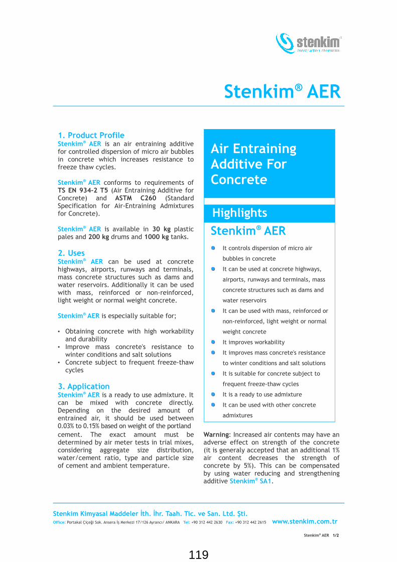
Stenkim® AER
1. Product ProfileStenkim® AER is an air entraining additive for controlled dispersion of micro air bubbles in concrete which increases resistance to freeze thaw cycles.
Stenkim® AER conforms to requirements of TS EN 934-2 T5 (Air Entraining Additive for Concrete) and ASTM C260 (Standard Specification for Air-Entraining Admixtures for Concrete).
Stenkim® AER is available in 30 kg plastic pales and 200 kg drums and 1000 kg tanks.
2. UsesStenkim® AER can be used at concrete highways, airports, runways and terminals, mass concrete structures such as dams and water reservoirs. Additionally it can be used with mass, reinforced or non-reinforced, light weight or normal weight concrete.
Stenkim® AER is especially suitable for;
• Obtaining concrete with high workability and durability
• Improve mass concrete's resistance to winter conditions and salt solutions
• Concrete subject to frequent freeze-thaw cycles
3. Application Stenkim® AER is a ready to use admixture. It can be mixed with concrete directly. Depending on the desired amount of entrained air, it should be used between 0.03% to 0.15% based on weight of the portland
Air Entraining Additive For Concrete
HighlightsStenkim® AER
It controls dispersion of micro air
bubbles in concrete
It can be used at concrete highways,
airports, runways and terminals, mass
concrete structures such as dams and
water reservoirs
It can be used with mass, reinforced or
non-reinforced, light weight or normal
weight concrete
It improves workability
It improves mass concrete's resistance
to winter conditions and salt solutions
It is suitable for concrete subject to
frequent freeze-thaw cycles
It is a ready to use admixture
It can be used with other concrete
admixtures
cement. The exact amount must be determined by air meter tests in trial mixes, considering aggregate size distribution, water/cement ratio, type and particle size of cement and ambient temperature.
Warning: Increased air contents may have an adverse effect on strength of the concrete (it is generaly accepted that an additional 1% air content decreases the strength of concrete by 5%). This can be compensated by using water reducing and strengthening additive Stenkim® SA1.
Stenkim Kimyasal Maddeler İth. İhr. Taah. Tic. ve San. Ltd. Şti.Office: Portakal Çiçeği Sok. Ansera İş Merkezi 17/126 Ayrancı/ ANKARA Tel: +90 312 442 2630 Fax: +90 312 442 2615 www.stenkim.com.tr
Stenkim® AER 1/2
119
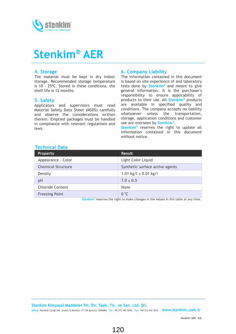
Stenkim® AER4. Storage The material must be kept in dry indoor storage. Recommended storage temperature is 10 – 25ºC. Stored in these conditions, the shelf life is 12 months.
5. SafetyApplicators and supervisors must read Material Safety Data Sheet (MSDS) carefully and observe the considerations written therein. Emptied packages must be handled in compliance with relevant regulations and laws.
6. Company LiabilityThe information contained in this document is based on site experience of and laboratory tests done by Stenkim® and meant to give general information. It is the purchaser's responsibility to ensure applicability of products to their use. All Stenkim® products are available in specified quality and conditions. The company accepts no liability whatsoever unless the transportation, storage, application conditions and customer use are overseen by Stenkim®.Stenkim® reserves the right to update all information contained in this document without notice.
Technical DataProperty Result
Appearance – Color Light Color Liquid
Chemical Structure Synthetic surface active agents
Density 1.01 kg/l ± 0.01 kg/l
pH 7.0 ± 0.5
Chloride Content None
Freezing Point 0 oC Stenkim® reserves the right to make changes in the values in this table at any time.
Stenkim Kimyasal Maddeler İth. İhr. Taah. Tic. ve San. Ltd. Şti.Office: Portakal Çiçeği Sok. Ansera İş Merkezi 17/126 Ayrancı/ ANKARA Tel: +90 312 442 2630 Fax: +90 312 442 2615 www.stenkim.com.tr
Stenkim® AER 2/2
120

Stenkim Dowel Bar
1. Product Description
Stenkim® Dowel Bar, is a plain carbon steel bar for used for concrete reinforcement in cut lengths and coils.
Stenkim® Dowel Bar conforms ASTM A 615 / A 615M Grade 60.
Stenkim® Dowel Bars coated by protective epoxy coaiting and conforms ASTM A 775/A 775M.
2. Uses
The use of appropriately sized Stenkim®
Dowel Bars is highly recommended for jointed concrete pavements that are subjected to high volumes of heavy traffic. Stenkim® Dowel Bars provide positive load transfer across pavement joints to greatly reduce critical deflections and stresses, thereby reducing the potential for pumping and faulting at joints, as well as slab cracking.
Technical Data of Dowel Bar
Diameter(mm)
Perimeter (mm)
Cross-Sectional Area (mm2)
Weight (kg/m)
20 62,8 314 2,466
50 157 1963 15,413*** For Length of Stenkim® Dowel Bar please contact with Stenkim®
Chemical Data of Dowel Bar
Standart Quality Code C M Si S P
TS 705 BÇ III-a/1-3 0,3 – 0,40 1,10 – 1,40 Max 0,15 Max 0,05 Max 0,05
1/1
121

StenMix® SUPA 200
1. Product ProfileStenMix® SUPA 200 is a ready to use naphthalene sulphonate based, high range, water reducing, superplasticising admixture for Portland cement concrete.
StenMix® SUPA 200 conforms to requirements of TS EN 934-2 Table 3 (High Range Water Reducer/Plasticizer Standard) and ASTM C 494 Type F (Standard Specification for Chemical Admixtures for Concrete – Water Reducing, High Range Admixtures).
StenMix® SUPA 200 is available in 35 kg plastic pales and 200 kg drums and 1200 kg tanks.
2. UsesStenMix® SUPA 200 is suitable for production of highly flowable concrete to improve surface finish and density. It is especially suitable for use with floor slabs, foundations, ceilings, walls, beams and columns with densely packed reinforcements. It can also be used with high early strength precast and prestressed concrete or when early removal of form work is required.
StenMix® SUPA 200 substantially improves workability when added to premixed concrete. It eliminates the risk of segregation during concrete transport and placement. It reduces the amount of vibration required. It does not retard curing reaction of the concrete, so the curing time is not increased. It decreases the permeability of the concrete by decreasing amount of water required.
High Range Water Reducer / Super Plasticizer
HighlightsStenMix® SUPA200
Naphthalene Sulphonate based high
range water reducing,
superplasticising admixture
It improves surface finish and density
It can be used with high early strength
precast and prestressed concrete
It improves workability
It eliminates the risk of segregation
during concrete transport and
placement
It reduces the amount of vibration
required
It decreases the permeability of the
concrete by decreasing amount of
water required by 15% - 30% when
dosage limits are observed
StenMix® SUPA 200, decreases the water requirement of the concrete by 15%-30% when dosage limits are observed.
3. Application The recommended dosage for StenMix® SUPA 200, is 0.8% to 3% based on weight of the cement.
Stenkim Kimyasal Maddeler İth. İhr. Taah. Tic. ve San. Ltd. Şti.Office: Portakal Çiçeği Sok. Ansera İş Merkezi 17/126 Ayrancı/ ANKARA Tel: +90 312 442 2630 Fax: +90 312 442 2615 www.stenkim.com.tr
Stenkim® SA1 1/2
122

StenMix® SUPA 200StenMix® SUPA 200, should be added with the mixing water. Most preferably StenMix® SUPA 200, is added to the gauging water at the plant, it should not be added to dry cement.Exact dosage must be determined by laboratory trial considering required workability and strength of concrete.
4. StorageThe material must be kept in dry indoor storages. Recommended storage temperature is 0 – 30ºC. Stored in these conditions, the shelf life is 12 months.
5. SafetyApplicators and supervisors must read Material Safety Data Sheet (MSDS) carefully and observe the considerations written therein. Emptied packages must be handled in compliance with relevant regulations and laws.
6. Company LiabilityThe information contained in this document is based on site experience of and laboratory tests done by Stenkim® and meant to give general information. It is the purchaser's responsibility to ensure applicability of products to their use. All Stenkim® products are available in specified quality and conditions. The company accepts no liability whatsoever unless the transportation, storage, application conditions and customer use are overseen by Stenkim®.Stenkim® reserves the right to update all information contained in this document without notice.
Technical DataProperty Result
Appearance – Color Brown Liquid
Chemical Structure Organic polymer based on naphthalene sulphonate
Density 1.20 kg/l ± 0.05 kg/l
pH 6.50 – 8.00
Solids Content (weight) 38 %Stenkim® reserves the right to make changes in the values in this table at any time .
Stenkim Kimyasal Maddeler İth. İhr. Taah. Tic. ve San. Ltd. Şti.Office: Portakal Çiçeği Sok. Ansera İş Merkezi 17/126 Ayrancı/ ANKARA Tel: +90 312 442 2630 Fax: +90 312 442 2615 www.stenkim.com.tr
Stenkim® SA1 2/2
123

StenSeal® 2K
1. Product ProfileStenSeal® 2K is a two component, cold applied, chemically curing, self leveling type, polyurethane based, coal tar modified, elastomeric material with high abrasion resistance and adhesion; suitable for heavy traffic conditions; resistant to jet fuels, hydraulic fluids and oils and dynamic movements. It is fully resistant to UV radiation.
StenSeal® 2K is classified as Type M, Grade P, Class 25, Use T according to ASTM C920.
StenSeal® 2K is available in 4 kg and 10 kg sets.
It has two types:For machine applications: StenSeal® 2K MAFor hand applications: StenSeal® 2K HA
2. UsesStenSeal® 2K is produced especially for runways, park areas, terminals and ramps, cargo fields and roads at airports. At the same time it is also a very compatible and economic joint sealant for highways subject to all types of traffic, secondary roads, bridge connections, ramps, stadium, industrial floors, pavements, fuel oil stations, roads and concrete fields at petrochemical and other industrial facilities. It is suitable for all kinds of horizontal outdoor joints.
3. Joint DesignJoint width must not be less than four times the expected movement or 6 mm. Up to 15 mm width, joint sealant depth must be equal to the width. Between 15 and 30 mm joint widths, sealant depth must be equal to
Jet Fuel Resistant, Cold Applied, Polyurethane Based, Self Leveling Type Joint Sealant
HighlightsStenSeal® 2K
It is polyurethane based, two
component.
It is cold applied.
It cures chemically.
It is self leveling.
It has high abrasion resistance and
excellent adhesion.
It is resistant to dynamic movements.
It is resistant to jet fuels, oils, diluted
acids and bases, various chemicals.
It can also be used in repairing cracks
in concrete pavements.
It is fully resistant to UV radiation.
Faster or slower curing can be
provided depending on the customer
needs.
80% of the width. For wider joints, sealant depth must be set to 30 mm. For adjusting depth backer material must be used inside the joint.For localizing the cracks caused by
contractions that may occur during and after curing at new concrete pavements, design and sealing of the contraction joints left before cure or saw cut after cure are also important. It is recommended that you refer
Stenkim Kimyasal Maddeler İth. İhr. Taah. Tic. ve San. Ltd. Şti.Office: Portakal Çiçeği Sok. Ansera İş Merkezi 17/126 Ayrancı/ ANKARA Tel: +90 312 442 2630 Fax: +90 312 442 2615 www.stenkim.com.tr
StenSeal® 2K 1/4
124

StenSeal® 2Kto our technical document on joint design.
4. Application4.1. Surface PreparationJoint surfaces must be clean and dry. Oil, grease, bitumen or sealant remains must be completely removed. Loose materials on the joint walls must be removed; broken joint walls must be repaired.
StenSeal® 2K is affected from water before curing like all other polyurethane materials. Therefore the joints must be dry and the sealant must not contact water until chemical curing occurs.
4.2. PrimerStenSeal® 2K can be used in concrete joints without primer. However, in any case primer application minimizes the negative effects of possible contamination, concrete moisture and loose materials. Therefore; StenAst® S is recommended for concrete, plastic, glass and all types of surfaces in permanent contact with water, StenAst® PU is recommended for wooden surfaces and polyurethane coatings, and StenAst® 2EP is recommended for metal surfaces.
4.3. Backer MaterialA rod which preferably does not adhere to the sealant must be placed in the joint in order to attain the sealant depth determined according to the joint width. Closed cell polyethylene foam rods are suitable for this purpose. Diameter of the rod must be 10 – 25% larger than the joint width; the rod must be placed tight in the joint. Rods must not be damaged during placement. In wide joints, semi-rigid materials like polystyrene foam can be used instead of rod. In such cases, it is helpful to place a polyethylene tape over backing material in order to prevent adhesion to the sealant.
4.4. MixingStenSeal® 2K consists of two components,
namely A and B, and these are packed in proportional mixing ratios.
StenSeal® 2K HA: First the container of component A is opened and it is homogenized for 2 – 3 minutes, then all of component B is poured onto component A and it is mixed via a low speed (100/500 rev/min) drill and a suitable paddle for 3 – 5 minutes. Longer mixing times are required to obtain a homogeneous mixture in manual mixing (not recommended). During mixing the mixer must be moved inside the container and it must be ensured that no air is trapped inside.
StenSeal® 2K MA: Machine type sealant is not suitable to be mixed by hand since it cures fast. However if the application machine has no separate mixer for homogenizing component A, component A must be homogenized by mixing alone for 2 – 3 minutes before it is poured in the machine.
4.5. ApplicationThe amount of sealant that can be used within the pot life must be determined by considering the application place and the capacity of the application apparatus. Mixed material must be used within its pot life. Solvents can not be used for thinning the sealant at the end of its pot life. Material at the end of its pot life must not be used.
In machine applications pot life is important for the tip section where the components mix together. If the application is interrupted for any reason, that section must be cleaned immediately. In hand applications prepared mixture is filled into a refillable type application apparatus with piston (sealant gun – applicator). In both application types, a nozzle with a diameter enabling it to enter into the joint must be fitted to the apparatus and while the sealant is applied this tip must be moved forward by sliding over the backer rod in the joint. Thus it is ensured that no gap is left under the sealant
Stenkim Kimyasal Maddeler İth. İhr. Taah. Tic. ve San. Ltd. Şti.Office: Portakal Çiçeği Sok. Ansera İş Merkezi 17/126 Ayrancı/ ANKARA Tel: +90 312 442 2630 Fax: +90 312 442 2615 www.stenkim.com.tr
StenSeal® 2K 2/4
125

StenSeal® 2Kand sufficient amount of sealant is used. After the application sealant surface can be finished by means of a spatula. Application can be carried out directly with a spatula.
It is recommended to tape both sides of the joint before starting application on joints especially where the decorative look is important. In this manner material smeared outside of the joint during the application is removed by pulling off the tape after the application.
Sealing cracksRepairing the cracks formed and ensuring impermeability is especially important on concrete pavements at airports and highways. StenSeal® 2K can be used for such purposes too. Generally it is helpful to saw the cracks to form a groove of minimum 10 mm depth and 6 mm width. Repair after saw cutting is sufficient at places where the cracks are infrequent. In case of severe cracking, coating for narrow cracks and combined sealing for wide cracks are recommended.
4.6. Accelerated CuringIn cases where curing is desired to be completed sooner, accelerator StenQuick PU supplied by the production company can be used. In order to attain a comfortable application time under very hot weather conditions, decelerating the curing may be desired; in such cases it is recommended to use inhibitor StenSlow PU.For curing times in these cases, please contact the producer.
4.7. LimitationsIt is not recommended for joints narrower than 5 mm. It must not be used in dirty, oily, bituminous and wet joints. In order to ensure a good adhesion, it is important to clean such joints before application. Despite its high mechanical resistance; studded tire, tire chain, high heeled shoes cause damage. During the application, ambient temperature
must not be higher than 35ºC and lower than 5ºC. If the application has to be carried out in other conditions, get recommendations from Stenkim®.
4.8.Application ToolsMixer, application gun, application machine, spatula. Professional quality tools must be used.
5. CleaningApplication devices and other sealant smudged devices must be cleaned before the sealant cures. For that purpose, tools first wiped with cloth or oakum must be cleaned with StenSolver CL or aromatic solvents such as toluene and xylene.
6. SafetyApplicators and supervisors must read Material Safety Data Sheet (MSDS) carefully and observe the considerations written therein. Emptied packages must be handled in compliance with relevant regulations and laws.
7. StorageThe material must be kept in dry indoor storages. Recommended storage temperature is 10 – 25ºC. Stored unopened in these conditions, the shelf life is 12 months.
8. MaintenanceDamaged parts should be repaired. If required, please refer to our Technical Support service regarding this matter.
9. Company LiabilityThe information contained in this document is based on site experience of and laboratory tests done by Stenkim® and meant to give general information. It is the purchaser's responsibility to ensure applicability of products to their use. All Stenkim® products are available in specified quality and conditions. The company accepts no liability whatsoever unless the transportation,
Stenkim Kimyasal Maddeler İth. İhr. Taah. Tic. ve San. Ltd. Şti.Office: Portakal Çiçeği Sok. Ansera İş Merkezi 17/126 Ayrancı/ ANKARA Tel: +90 312 442 2630 Fax: +90 312 442 2615 www.stenkim.com.tr
StenSeal® 2K 3/4
126

StenSeal® 2Kstorage, application conditions and customer use are overseen by Stenkim®. Stenkim® reserves the right to update all
information contained in this document without notice.
Technical DataProperty Method Result
Base Polymer 2 Component Polyurethane
Solids Content % 100
Movement Capability Expansion 25%
Movement Capability Contraction 25%
Color Black
Elongation at Break ASTM D 412 Die B >400%
Density (A+B) 1.40±0.05 g/cm3
Durometer Hardness (Shore) ASTM D 2240 A25±5
Resilience TS 5926 EN 14188-2 >98%
Penetration 0.5 mm
Pot life of the mixture @20°C HA 2 hours
Pot life of the mixture @20°C MA 10 minutes
Tack free time @20ºC HA/MA TS 5926 EN 14188-2 8 hours / 1 hour
Cure Time For Light Trafficability @20°C HA/MA 24 hours / 6 hours
Cure Time For Heavy Trafficability @20°C HA/MA 2 days / 12 hours
Cure Time For Chemical Resistance @20°C 4 days
RELATED STANDARDS: TS 5926 EN ISO 14188-2, ASTM D 1854, ASTM C 920, MIL SS-S 200E, BS 5212
Stenkim® reserves the right to make changes in the values in this table at any time.
Stenkim Kimyasal Maddeler İth. İhr. Taah. Tic. ve San. Ltd. Şti.Office: Portakal Çiçeği Sok. Ansera İş Merkezi 17/126 Ayrancı/ ANKARA Tel: +90 312 442 2630 Fax: +90 312 442 2615 www.stenkim.com.tr
StenSeal® 2K 4/4
127

Erbil OfficeEinkawa
Tel: 00964 (0) 770 511 1003
00964 (0) 750 777 1003
Sulaimani Office,
Tel: 00964 (0) 770 511 1002
00964 (0) 770 156 4149
00964 (0) 750 355 1002
Kirkuk Head Quarter – Almaz St.
Cheman Office,
Tel: 00964 (0) 750 735 3825
00964 (0) 770 511 3700
Typical Cross Section
For
Concrete Pavement
Cross Section Design
Prepared By: Dalo Group Engineering
Reviewed By :- Eng. Hamno Aziz
Approved By :- Eng. Hamno Aziz
128

LONGITUDINAL CONTRACTION JOINTSCALE: 1/10
DETAIL C
SCALE: 1/10
T.C.J. / L.C.J. SAW CUT DETAIL
DETAIL A
DETAIL D
SCALE: 1/10
C.J. SAW CUT DETAIL
TRANSVERSE CONTRACTION JOINTSCALE: 1/10
DETAIL B
TRANSVERSE CONSTRUCTION JOINT
SCALE: 1/10
DETAIL CEXPANSION JOINT
SCALE: 1/10
DETAIL D
(WHERE THE OPERATION STOPS)
DETAIL D
SCALE: 1/10EXPANSION JOINT
129
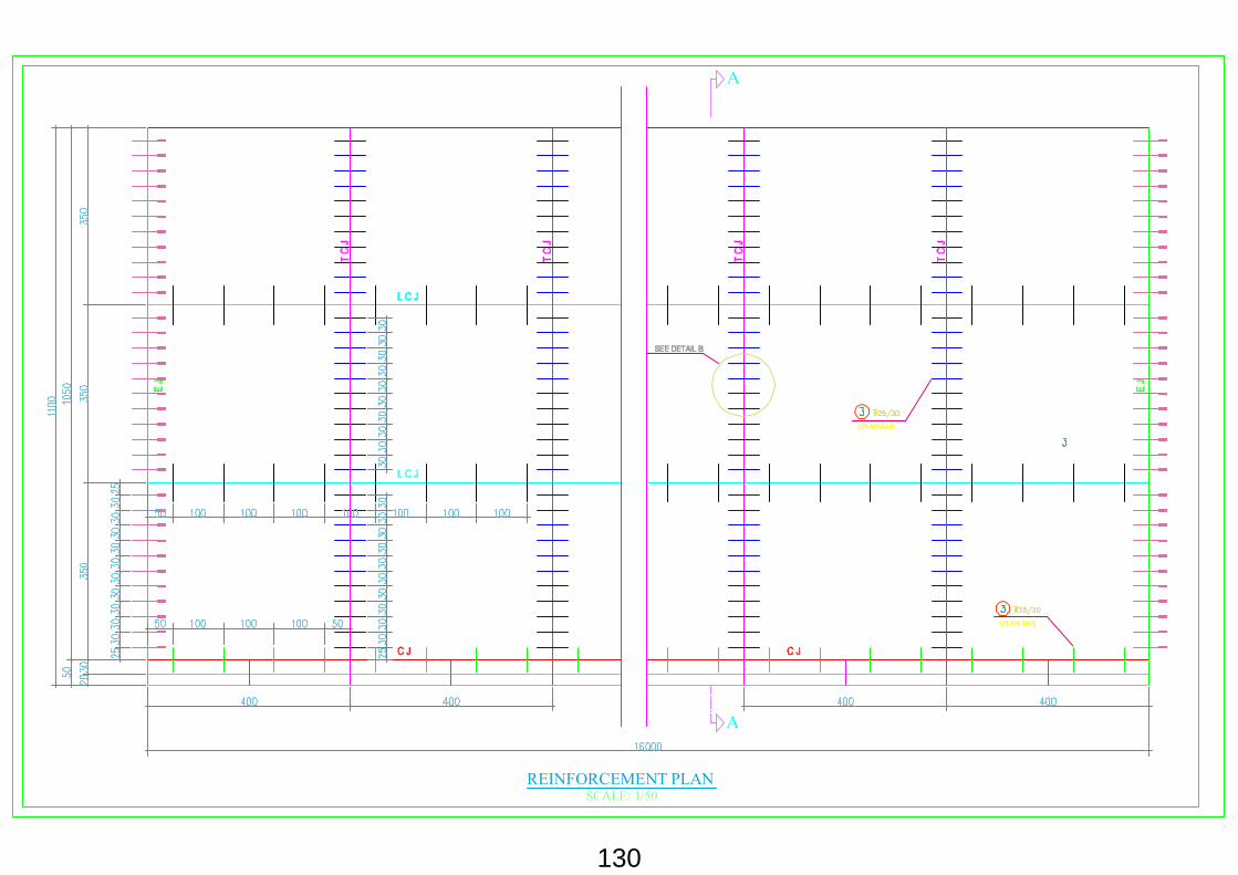
SCALE: 1/50REINFORCEMENT PLAN
A
A
130
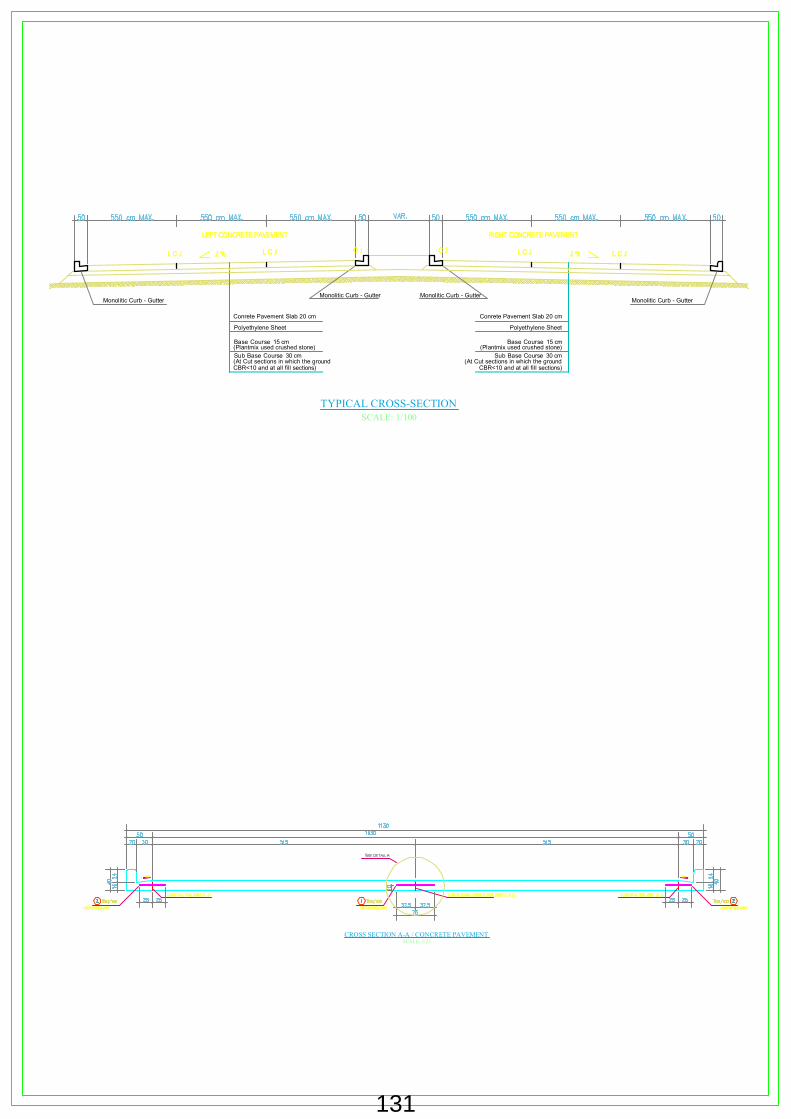
Base Course 15 cm(Plantmix used crushed stone)
Conrete Pavement Slab 20 cm
Sub Base Course 30 cm(At Cut sections in which the ground CBR<10 and at all fill sections)
SCALE: 1/25
CROSS SECTION A-A / CONCRETE PAVEMENT
SCALE: 1/100
TYPICAL CROSS-SECTION
Polyethylene Sheet
Monolitic Curb - GutterMonolitic Curb - Gutter
Base Course 15 cm(Plantmix used crushed stone)
Conrete Pavement Slab 20 cm
Sub Base Course 30 cm(At Cut sections in which the ground
CBR<10 and at all fill sections)
Polyethylene Sheet
Monolitic Curb - GutterMonolitic Curb - Gutter
131