concrete pipe association of …...pipe design for external load 1.1 loads on concrete pi pes the...
TRANSCRIPT

www.cpaa.asn.auConcrete Pipe Associationof Australasia
513
Pipe Design Manufactureand Testing
,,C W Simpson, Dip CE RMIT
We in Australia, are fortunate that the two processes most used throughout the world forthemaking of high-density/high-strength concrete pipe were developed in this country.
In the days when the Australian Standard CA2 did not recognize concrete. strengths greaterthan 4000 Ib/in 2 , the concrete in concrete pipes in Australia had a strength double this figure.
Concrete pipe manufacturers found that their pipes performed much better in practicli thanwas indicated by calculations based on conventional formulas and bending momentco-efficients for thi n rings. I
Therefore they developed their own methods of design, empirical to some extent; methodswhich have been refined and confirmed by decades of pipe testing,
1. PIPE DESIGN FOR EXTERNAL LOAD
1.1 Loads on concrete pi pes
The calculation of loads on pipes in most countries, including Australia, is still based onthe work of Americans, Marston, Spangler and Schlick, of the University of Iowa.
The Australian Standard for concrete pipe laying design is A.S. CA33-1962. The data inthis standard enables the field load ona concrete pipe to be determined.
Examples of calcu lations are given at the back of the Standard. The data does notnecessarily apply to pipes made from other materials.
The most common error in load calculation is the use of the trench formula We = CtwB 2
for trench widths beyond the range to which it applies. In the formula any increase intrench width B produces an increase in the load We' Obviously the load on a pipe does notincrease indefinitely as the trench width is increased.
A trench width is reached beyond which the load on the pipe remains the same. Thisoccurs when the load We equals CewD 2, D being the outside diameter of the pipe, afterwhich the formula We = Ct wB 2 must not be used.
The support under the pipe is most important. Point or line support in the trench must beavoided. As you would expect, the more distributed the support, the greater the load thatthe pipe can carry. For example a pipe which can be considered to be supported overanarc of 1200 for its full length will carry about 25% more load than one supported over a
1
900 arc, and about 70% more than one supported along a longitudinal line. Concentratedsupport, such as a pipe resting on its socket, or resting on a brick or timber block whichhas been used for levelling purposes, must be avoided. When concrete bedding is used, thepipe should contain concentric (rather than elliptical) reinforcement.
After the field load is calculated, it can be converted into an equivalent factory test loadby dividing by a load factor.
A.S. CA33·1962 gives load factors for a variety of installation conditions. Factory testloads have been standardized into five classes, C, S: X, y & Z. C Class appl ies only tounreinforced pipes. Z Class is the heaviest load class listed in AS 1342-1973, and coversmost needs, but it is not a top limit for reinforced concrete pipes. R.C. pipes can be madeby many manufacturers with a load carrying capacity of double this amount. Pipes greaterthan Z Class are referred to as 1.25Z, 1.5Z, etc.
1.2 Specifications
Specifications can be of three basic types, -
(al Performance, where the pipe must pass tests to make positively sure that it is fit todo the job for which it is intended.
(b) Prescription, where the purchaser designs the pipe himself for the field load,nominating sizes, reinforcement details, concrete mix details, manufacturingprocedures, etc., and provides supervision of manufacture to ensure that his wishesare carried out. By providing the design, the Purchaser takes the responsibility, andhopes that his theories have produced a pipe which will not fail under field load.
(c) Design, where the purchaser nominates permissible design stresses in the belief thatthe actual stress can be accurately determined theoretically and that a pipedesigned within such limits will not fail under field loads.
Prescription and Design specifications are used for buildi'ngs and structures whichare difficult or impossible to test. They are of necessity conservative.
Performance specifications are used for products which can be tested. The purchaserhas the assurance that the product will perform as desired in practice, and that thedesign is economical.
The Performance type is used for concrete pipes in Australia, Britain, South Africaand New Zealand. The prescription type is used in North America, though it shouldbe noted that the designs were based on the results of performance tests.
The Australian Standard for precast concrete drainage pipes is AS 1342-1973. It isquite stringent compared with overseas standards. It requires that the pipes pass anUltimate Test Load equal to 1.5 times the Cracking Test Load, which compares with1.25 in Britain and 1.25 for Class y.. pipes in North America. It requires that themaximum crack width at cracking load be 0.15 mm (0.006"1 compared with 0.010"in Britain and North America. Its requirements regarding absorption are also strictcompared with overseas standards.
The fact that the ultimate load is required to be 1.5 times the crack·ing load meansthat the pipe has a safety factor of 1.5 against failure.
1.3 Design methods
The different pipe manufacturers use different design methods, each manufacturer havingto consider his own manufacturi ng process, the materials he uses, the concrete strength heis able to achieve, and the results of performance tests over many years.
2

A detailed explanation of the different methods is not possible. However, it should bepointed out that there is no need for concern if a check calculation using conventionalformulas indicates a high 'apparent' stress. Bending moments and stresses calculated byconventional formulas usually exceed actual at critical points. There are several reasonsfor this, e.g.-
(a) The test load is in theory a point load, but in practice there is some distribution.
(b) The commonly-used bending moment co-efficients are based on loads on thin rings,whereas concrete pipes are relatively thick rings.
(c) The methods of pipe manufacture developed in Australia give very high concretestrengths, often beyond the range covered by standard codes for concrete.
T-his can be illustrated, if further evidence is required, by calculating the apparentstresses in pipes specified in the American prescription specification ASTMC76-1972. The apparent stresses will be found to be unreal istically high, despite thefact that the concrete strengths specified are much lower than those obtained bypipe manufacturers in Australia. In fact of course, the actual stress is not as high asthe calculation indicates.
1.4 Unreinforced concrete pipe ,,This type of pipe is sometimes used for sewer drains. It is rarely specified for pipes over600 mm (24") diameter. Above that diameter R.C. pipes should be used with thenecessa~ycover to the reinforcement.
It is not good engineering to specify unreinforced concrete for load-bearing structures,because the compressive strength of the concrete is not fully-util ized.
For example, it is unlikely that any engineer these days would design an unreinforcedbeam to carry heavy loads, even in a corrosive environment.
1.5 Reinforced concrete pipeTypical bending moment diagrams for pipes under external load are shown below-
Earth load Self weight ofpipe& water
Test loadin factory
The critical points are at the bottom, top and sides. The negative moment at the bottomand top puts the inside face in tension. The positive moment at the sides puts theoutside face in tension. Therefore the most economical type of reinforcement is onewith an elliptical shape, placed close to the inside face at bottom and top, and close tothe outside face at the sides.
3

In small diameter pipes the walls are not thick enough for elliptical reinforcement to bepractical, so single circular cages are used.
SingleCircular
Elliptical DoubleCircular
CircularElliptical
In large diameter pipes, or pipes under very high external load, it is often necessary touse an inner and an outer reinforcing cage, which may be in the form of two circularcages, or a circular and an elliptical cage.
2. PIPE DESIGN FOR INTERNAL PRESSURE2.1 Determination of factory test pressu re
The factory test pressure must stress the pipe at least as much as the worst set of pipeline operating conditions is likely to do. It is usually set by the purchaser. Someauthorities add a fixed amount to the working pressure in the pipeline to obtain thefactory test pressure. Others add a fixed percentage.
A.S. 1392-1974 recommends that test pressure be 20% greater than the workingpressure where the working pressure is the sum of the static and dynamic (e.g. waterhammer) pressures.
2.2 SpecificationThe Australian Standard is A.S. 1392-1974.It is essentially a performance specification but has some stress limitations.
2.3 Design methodsThe tension in the shell due to the test pressure is calculated just as it would be for anypressure vessel. The tension is reckoned to be taken by the steel reinforcement alone. A.S.1392 limits the tensile stress in the reinforcement to 140 MPa (20,000 Ib/in 2 ) for harddrawn wire to A.S. 1303-1973.
A.S. 1392 also limits the resultant stress in the concrete (considering the transformedsection) to a maximum of 2.8 MPa (400 Ib/in2 ). In fact pipe designers use design stresseslower than these figures in many cases.
Reinforced concrete pipes have the additional safeguard, that should they be cracked byan unpredicted surge in the pipeline or an abnormal wheel load on top of the pipe, thecrack will close when the load passes, and will slowly seal due to the autogenous healingproperty of good concrete.
4

3. PIPE DESIGN FOR COMBINED LOADS
3.1 Combined loading
Almost every pressure pipe laid has to carry external load as well as internal pressure, so itis important - particularly under roads, or where the earth fill over the pipe exceeds 1metre - that the combined effect is considered.
3.2 Specification
Appendix F of A.S. 1392-1974 covers this situation.
3.3 Design methods
It is difficult and uneconomical to apply external load and internal pressure to a pipe in afactory.
Therefore a method has been devised whereby the combined load test is replaced by twoseparate tests, i.e. an enlarged external load test and an enlarged internal pressure test.That is, in place of a combined test with internal pressure Pw and cracking loadj:¥,Appendix F of A.S. 1392 prescribes a separate pressure test with Pw increased to Pt and aseparate load test with ~ increased to T. ,
The pipe is designed for factory test pressure Pt, then the design is checked to ensure thatthe pipe will pass external load T; or vice versa, depending which test is likely to be themost critical.
4. CONCRETE PIPE MANUFACTURE
4.1 Methods
Australian pipe manufacturers are world leaders in methods for making steel reinforcingcages and high strength concrete pipes. Continuously welded spiral-wound reinforcingcages are almost universally used in this country, whereas in America it isstill common forcages to be fabricated from flat mesh. Machine-made spiral-wound cages are very accurateand economical.
,The spinning and roller-suspension pipe-making processes, both developed many yearsago, are still leaders in the high-strength concrete pipe field. Both processes use centrifugalforce, vibration, and roll ing, to different degrees to obtain dense concrete.
4.2 QualityVery low water/cement ratios and high densities are features of Australian pipe-makingprocesses. A characteristic concrete strength (the strength above which 97%% of resultswill fall) of 50 MPa (7,250 Ib/in2 ) is easily attained.
Concrete strengths of 70 MPa are common, and of course durability is excellent.
Both pipe-making processes allow accurate positioning of the reinforcement cages. Thecage is solidly and effectively embedded in the concrete. This cannot be said of allprocesses.
5

4.3 Quality Control
As with all machine-made factory products, quality is easier to control than is the casewith in-situ work in the field. Factory work is unaffected by the weather, varying trenchconditions, or the difficulty of providing and operating pipe-casting equipment in remoteareas. A built-in control is the low water-cement ratio, which is inherent in the processes.
Factories which demonstrate that their products comply with the requirements of theAustralian Standards for pipes, can be licensed to use the S.A.A. mark on their products.
However, some companies regard this mark as of doubtful benefit, because the cost ofmaintaining the license is appreciable, yet many purchasers consider only cost and notquality when buying pipes.
5, PIPE TESTING
5.1 Types of tests
Pipes are regularly tested in accordance with Australian standards for load carryingcapacity, hydrostatic pressure capacity, joint water-tightness, absorption, and materialquality. Pipes are inspected for dimensional correctness, cover thickness, and internalfinish. '
5.2 Frequency of major tests
Tests for load-bearing capacity are carried out at the rate of one pipe in every fifty ifrequested by the purchaser.
Every pipe in a pressure pipeline is tested at the factory before delivery, because thefailure of one pipe could ruin the whole line.
5.3 Strength gain subsequent to test
After the concrete pipe is laid it spends the rest of its long life in ideal moist-curingconditions, so the strength of the pipe increases. The Purchaser therefore has the addedcomfort that the pipe in the line is stronger than it was when it passed the tests. I
6

17
Installation ofReinforced Concrete Pipes
,,NIGEL D. KNOWLES,
BA, BAI, MIE AUST.
1 INTRODUCTION
A reinforced concrete pipe is a very forgiving product in many ways. It needs to be whenone observes the way in which it is often installE!d.
An internal inspection of many in-service pipelines will show evidence tha,t there is more toproper handling and laying of pipes than the average site foreman ever imagined, or the siteEngineer in some cases.
It is also true that designers should have had site experience, to appreciate field conditions,before pressing the buttons of their calculator. But whether the Engineer has design or siteresponsibility, how much understanding does he have of the design and installationlimitations of proper pipe laying?
If the owner is to .get a good job at the right price there must be an adequate understandingby all the parties' he has hired, as to what is required in the proper design and properinstallation of a concrete pipe.
To avoid surprises as the project progresses the designer must possess detailed informationof the site, have knowledge of the equipment likely to be used and specify the projectaccordingly. The installation contractor on his part must bid and be prepared to supervisethe work in accordance with the limitations imposed by that specification. The pipe's lifedepends on it.
2 AN UNDERSTANDING OFTHE LOADS THAT ACT ON A PIPE
2.01 Scope
Before consideration is given to the methods of calculating the loads transmittedto a buried pipe a basic understanding of the way in which these loads act isimportant. The major load sustained on a line, installed at a reasonable depth isthe superimposed soil load. To analyse the way in which these soil loads act threedifferent major installation systems have to be understood.

Trench installationEmbankment installationJacked or tunnelled installation
These three systems can be further subdivided, diagrammatically, as shown in Fig. 1.
2.02 Trench Installation
In this system of installation the pipe is normally laid in a relatively narrowtrench, excavated in undisturbed soil, and then backfilled to the proposed groundlevel. The backfill material will tend to settle, relative to the undisturbed soil inwhich the trench has been excavated. This relative settlement of the backfillgenerates upward frictional forces which reduce the load on the pipe, such thatthe backfill load is equal to the weight of the column of backfill within thetrench, minus the upward friction forces (Fig. 2).
2.03 Wider Trench Condition
As the trench width is increased, the size of the column of backfill increases,imposing a greater load which the pipe must support (Fig. 3). As the trench widthis further increased for any given pipe size, backfill material and trench depth, alimiting width is reached, beyond which the trench width no longer affects thebackfill load on the pipe. The limiting width at which this occurs is defined asthe "Transition Width".
2.04 Transition and Wide Trench Conditions
To understand the transition width concept further, assume that the pipe isinstalled in an infinitely wide trench. The concrete pipe is relatively rigidcompared to the semi-elastic soil surrounding it. The columns of fill adjacent tothe sides of the pipe will settle downward more than the column of fill directlyabove the pipe. This relative settlement, generates frictional forces in the soi Icolumn above the pipe and transfers a greater load on to the pipe itself (Fig. 4).
Now assume that the same pipe is installed in a relatively wide trench. Thebackfill can be considered to act in seven interrelated columns (Fig. 5). The twooutside columns transfer their load to the trench walls, the intermediate columnstransfer their load to the bottom of the trench and the two inner friction columnstransfer their load to the pipe. The load carried by the pipe in this condition is nogreater than that generated by an infinitely wide trench.
Next assume the same pipe is installed in_a narrower trench and one of such widththat the "intermediate-columns" have been eliminated (Fig. 6). For this conditionthe entire load is being carried by the trench walls and the pipe. This is the"Transition Width Condition". The load transferred to the pipe is similar to thatcarried when the trench is WIDE and INFINITELY WIDE.
However, if the trench is once again made narrower than the Transition Width theload transmitted to the pipe is reduced and no longer is a function of the diameterof the pipe, but instead is controlled by the width of the trench. This condition isdefined as a NARROW TRENCH.
18

DESIGNERSU~DERSTANDING.
I~STALLER5
UNDERSTANDI t-J G
SPECIFICATION _~WINGS
SUPERVISORS
COMPLETION
OR
BID PRICEEQUIPMENT
,,
SPECI FI CATiONDRAWIl-lGS SUPERVISORS UNDERSTANDING
Cl),SSIFICATIO~ OF rowsTRLlcnON COWDITIONS1m DETERlo1ltJATION OF LOADS ON PIPE.
~11JRAl N"11JRAL W....11JR.... L(;ROUND CROON 0 GR)UND.
19
BID PRICEEQUIPMENT
o

TRENCH INSTALLATION.
FIG.2.
WIDER TRENCH INSTALLATION.
-INFINITE TRENCH WIDTH.
FIG.4.
WIDE TRENCH CO~DITION.
FIG. 3. FIG.5.
20

TRA~SITION CONDITION.
FIG. 6.
FIG.7.
EMBANKMENT INSTALLATION.POOR COMPACTION OF SIDEFILL
FIG.a.
ZERO PROJECTING INSTALLATiON.)W~t11t' «, '\::f~~WI$
t', .~ NO LOAD~,:~ 7J?ANSFER~.,~ .
FIG.9.
21

NARROW TRENCH INSTALLATION.
FIG. 10.
IMPERFECT TRENCH INSTALLATION.
FIG. II.
22
JACKED OR TUNNE.LEDINSTALLATION
i p~~.I
t COHESION(If\LOAO
Ir1r' TiiiiJSFER
I FRICTIOIJ
I JI loADI I TRANSFER
II
FIG. 12.
TUNNELED INROCK.
FIG. 13.

2.05 Specifying Trench Width
Because of the significant influence of the trench width, in the narrow trenchcondition, on the superimposed load transmitted to the pipe, the maximumtrench width, used in the design, should be specified on the project drawings andshould not be exceeded on site without engineering approval. However, shouldthe transition width, or greater, have been assumed in the design, then control ofthe excavation on site becomes unnecessary and the site supervisor should beaware of this fact.
2.06 Embankment Installation Conditions- Positive Projection
This system of installation occurs when the pipe is laid in a shallow bed andcovered with fill material, forming an embankment. Similar concepts, oftransmission of the loads to the pipe, apply to this condition as have beenillustrated above. Positive project embankment condition is the same condition asa wide trench (beyond the transition width). The degree of compaction given tothe backfill (side fill) will determine the degree of settlement and the loadsustained by the pipe (F ig. 8).
2.07 Embankment - Zero Projection ,,Zero projection exists when a pipe is installed under an embankment in a narrowtrench of such a depth that the top of the pipe is at the same elevation as theoriginal ground. Differential settlement is not present and consequently the soilload transmitted to the pipe is equal to the column of fill above the pipe itself(Fig.9).
2.08 Embankment Condition - Negative Projection
When the pipe is installed in a deeper trench, under an embankment, such that thetop of the pipe is below the elevation of the original ground, the condition istermed "Negative Projection" (Fig. 10), and simulates a trench condition. The soilload transmitted to the pipe is equal to the weight of the column of fill, as wide asthe trench and as deep as the embankment over the pipe, minus the frictionalforces transmitted to the walls of the trench. The magnitude of these frictionalforces is dependent on the depth and width of the trench' and the degree ofcompaction given to the side fill.
2.09 Embankment Condition - "Imperfect" or "Induced" Trench
Positive projection (wide trench) conditions transmit the most severe soi I loads tothe pipe. When high embankment requirements are also encountered it is possible,with skill and care, to reduce the total load that the pipe has to support. Themethod used is termed the "imperfect trench" or "induced trench" condition(Fig. 11).However this method of installation is not easily attained in the field and themanufacturer should be consulted to ascertain if an extra strength pipe can besupplied to suit the condition.
23

The construction sequence required to achieve this condition can be either of tinefollowing:-
OR
(a) Install the pipe on the bedding.
(b) Compact the fill around each sideof the pipe with care, for a lateraldistance equal to twice the outside diameter of the pipe or3600 mm, whichever is least butstill practical. This process shouldbe extended to at least one pipediameter above the top of thepipe, with care not to damagethe pipe.
(c) Excavate.a trench in the fill abovethe pipe as wide as the pipe andas deep as practical.
(d) Refill the trench with loose,compressible material, straw orbrush.
(e) Complete the embankment in theusual way.
2.10 Tunnel orJacked Installation
(a) Complete the embankment toa reduced level as deep asthe designed "induced" or"imperfect" trench depth beforeinstalling the pipe.
(b) Excavate the required trenchand lay the pipe on bedding.
(c) Backfill the pipe in the normalway to the top.
(d) Complete the backfill of thetrench with loose, compressiblematerial.
(e) Complete the embankment inthe usual way to finishedelevation.
24
In pipe jacking, axial loads can be minimised by ensuring a relatively uniformdistribution of load around the periphery of the pipe. The soil load is less than asimilar pipe would be required to withstand, had it been installed by openexcavation and backfill. There is a vertical plane of cohesion developed in thecolumn of soil above the excavation (F ig. 12). In stable rock the pipe acts as aliner only for the tunnelled excavation (Fig. 13).
3 BEDDING
The purpose of providing a bedding for a pipeline is to distribute the supportaround the lower exterior surface of the pipe and thus reduce stressconcentrations within the pipe wall. The width of the bedding contact and itsuniformity of support will determine the load that a concrete pipe will carry.
When considering a bedding medium it is important to select a material which iseconomically available onto the site and which can be installed in such a way as togive the necessary uniform support. Since most granular materials, even aftercompaction and shaping will move to take up the irregularities of the pipe as itis laid, they provide ideal load distribution. Cleaned coarse gravel, well rounded peagravel or well graded crushed rock are all suitable when compacted and shaped tothe outline of the pipe.
The designer has to consider the economics of the total installation of beddingand pipe. He can specify a lower quality type of bedding but then is forced toselect a higher strength pipe.

4 BACKFILL
In the same way as the bedding is constructed to give uniform support to thelower surface of the pipe, backfill, or more specifically "side fill", is installed togive uniform support to the exterior sides of the pipe. Lack of side support willcause lateral distortion of the pipe and may result in cracking.
If the designer believes that insufficient attention may be given to this on site heshould take that -contingency into account when selecting the class of pipe for thejob.
However, if it is more economical to compact the backfill it must be undertakenin no more than 150 mm layers, to at least 90% of the maximum dry density, asassessed by the modified Proctor test method. The installation contractor shouldrecognise the significance of this requirement and cost his bid and supervise hisconstruction accordingly.
5 CALCULATION OF SUPERIMPOSED LOADS
5.01 Internal Water Load (Ww)
Internal Water Load (Ww ) need only be taken into account when the pipe is laidon "0" class bedding.
5.02 Static Loads due to fill material (general formula)
We = Cw8 2 x (9.8 x 10-3 ) in metric measurement.
Where:- 8 is trench width or outside diameter as appropriate.
We is the vertical load per unit length acting on the pipe due to soil.
w is the density of the soil.
C is a dimensionless coefficient that measures the effect of:-
(a) the ratio of height of fill to the width of trench or pipeoutside diameter.
(b) shearing forces developed between the interior and adjacentearth columns, and
(cl direction and amount of relative settlement between interiorand adjacent soil columns for embankment conditions.
5.03 Narrow Trench
We = Ct w 8 2 x (9.8 x 10-3 ), using Graph 1.
5.04 Wide Trench
We = Ce w 0 2 x (9.8 x 10-3 ), using Graph 2.
Remember that "wide trench" and "positive projection" Embankment are thesame. It is necessary to calculate the "Projection ratio" which is the proportionof the pipe diameter projecting above natural surface. It is also necessary toselect the appropriate settlement ratio - discussed later. See sketches on Pages21 to 26.
25

26
5.05 Transition Width
In order to recognise this condition more readily Graph 3 has been provided.
5.06 Embankment Condition - Positive Projection
As discussed for Wide Trench Condition.
5.07 Embankment Condition - "Imperfect" or "Induced" Trench
We = Cn w 82 (9.8 x 10⁻³ ), using Graph 4.
It ~s necessary to calculate p', where p' = ~ and select appropriate settlementratio.
5.08 Vertical loads due to Superimposed Concentrated Loads onthe Surface
po:Wc = cp L x (9.8 x 1O-3 ), where Cp has the value given in Graph 5, appropriateto the ratios
L 02H and 2H where: L = length of pipe assumed to be supporting the
concentrated load calculated by the formula:-
L = 1.15H + 0 + S (but not to exceed thelength of the pipe)
where H = height of fillo = Diam. of the PipeS = length of concentrated load along
the pipe.

VALU
ESOF
His
0I
23
45
67
89
10II
1213
14\5
IG4-
5
CU
RV
EA
4II
1111
111
jII
!11
1111
1111
1111
1111
1111
1111
1111
1111
1111
1111
1111
1111
1111
1111
1111
1111
IIU
kHm
llllllllllllllll!1
11
1C
UR
VE
B
RE
AD
TO
P4
LEF
T~
CU
RvE
C;0 >
3"x:
: - ,C
UQ
VE
E11
1111
1II
1111
1111
1111
1111
1111
1111
1111
1111
1111
1111
1<
Z>
:>r
t-c=
'}:J
rnA
Jti
l<
:10
I\)
~C
UR
VE
A1-
4»
/;l~
~-..
.Jr-
'2C
UR
VE
B~
ec
~C
UR
VE
Crn
OJ8
-i
mti
lto
Im
A:l
(J',
1-2
)(."T
lf'T
'IC
UR
VE
D0
,-..
...
"Z
0"
<Dn
()
"C
UR
VE
E1-
0P
~m
:r:~
Iz
0-;
I(')
J'~
0 Z
CU
RVE
Kp..
KJl'
MAT
ERIA
L0·
8a
z:-i
A'11
SATU
RAT
EDC
LAY(
FUJ/
O)
2J8
'13
NO
RM
ALW
ETcv
.y0
RE
AD
BOTT
OM
;l<
IGH
T11
111
1111
1111
11I!
!!rm
n111
1111
1111
1111
1111
1111
1111
1111
1111
c-1
5SA
I·JOY
cLAY
O·G
Al
Z~
0.'''5
CLA
YEY
SAt-J
DC
~,1
924
LOO
SEG
RAI
IIULA
RM
AT'L
~0·
4
0''2 0
00·
10-
20·
30,
40·
50,
"07
0-8
o·~
1·0
J.I1·
2\·3
\·41·
5I·
'i
VALU
ESO
FH/
s

INC
OM
PLE
TE~Ec.nON
~OlTION
zot.l
E
I.TH
EC
lJQ
VES
~RE
DR
AWW
R:>R
AvA
WE
OF
Kp
:0
·19
24
WH
IOI
IS
AP
PllC
A8L
E10
GR
ANU
LAl:C
!S
OIL
SW'~UT
O:>
HES
ION
.nlE
VA
LUE
1$S
LIG
HT
L'i
CO
NS
fRV
An
VE
R:)
RO
THE
RM
AT
ER
IALS
.
NO
TE:
~ 0 f"T1
-i
C)
~X
l('T
1
~z::
:t:
(')
tv::r
:I
><
:Z
>0
r-~
C(b
m"'
0•
Vl
0(')
0(J
'),~
"T1
--i
E ~("
')
<0 m
rn><
.."
r--
.""'
0(D
n;0
()l
m0
xZ
c....
°1
~f'T
1(')
UI
z:-;
.......
."
00
Z'"~
I~c:
r »» z ~ ~ ("
T1 z :-i
IGIS
1413
12
0'\
(.~' "
109
8
r s"
SEff
iI:M
El-
lTRA
llOp
.Pl
<O.JE
CnO
t-JRA
TIO
0.0(i
o.'
7G
5
~ ~ tJ ")
J!J ~.~
43
2
24 23 Zl
21 ~ 19 18 11 Ib 15 \4- /3
(112
u.. o
/IV
)l\
)w
lO0:>
:::>
-I
9~
8 7 , 5 .. 3 2 J 0
VALU
ESOF
HID.

-t '"~ z: (j') -
C')
-i
7::J
->
0'0
z:X ()
.)~ ~ I C X - -i 0 " z: » }O 7:J
0 ~ ~ m Z n ::x:
n 0 % 2 -t - 0 Z
4.5
4.0
3.8
mot
res
"
3.5
Kf
=K
f'=
0.1
65
2.0
2.1i
3.0
B=
wid
tho
ftre
nch
atto
po
fpip
e,in
met
res
1.5
1.0
Ass
umed
Back
fill
Den
sity
2000
kg/m
3
""-":
0~~~
:--...: ".....
.........
.........~
"-.....
... r-........
.........
......
....EX
AM
PLE
",~~,
........,
.........~r-....
.........,
.........r-...
............,
1A
n18
00rp
mdi
amet
erpi
pe.
~, '""
wllh
4.5
met
r..
01fin
abov
aI\.
tha
crow
n.ha
sa
"an
silio
n\
I\.\.'"
:'-."
'"
........
:.....
't'--
..~
':!.:t""
"...w
idth
<at
the
crow
nof
tho
pipe
)01
3.8
mol
ros.
Tho
ro·
\1\
1\'
'\~'\
I\..
r'\.
r'\."
i'.i'-.
r"-,.
.,I'Sc
b~"""
"-I"-
.fo
rea
tren
chw
idth
whi
chIs
loss
than
this
figur
oI.
torm
od
~\~
\1\
1\.1
\.\.1
'\"I
\..
,,~q
,~~;
:'~,
"~
ana
rrow
tren
chan
dab
ove
this
flSU
roI.
cons
ider
edan
,1\
1\1\
\I\.
i\.1\
'\'0;
1~">~
"'~
""f'
emba
nkm
ent
Inpo
sitiv
epr
o·
~'--
"'>......
...~
jecl
ion.
1\\
\~
\~
~~~~
_;\~\,
r\."-
i'."
r".
4.5
mel
res
\1
\\\%-~~\\
1\r\.
1\, I\.
.I\
.'"
\'\;
,-..~.
~
"\.
~~
rr,f-'\
\\.\
\.\.
I\.
~-_~
_:\
~1\
1\\
'.\
1\\.
'\I\.
,"
I;\
\"
\\
\\
1\'\
r\\
I\.1'\
'\'\
\1\
~\
\\
\\
1\\
\.\.
\.
\\
\\
\\
\\.
\\.
\.\.
I
\\
\\
\~
\i\
\\.
\\
~\
~\
\1\
\1\
)
1\1\
1\1\
,1\
\, [
\\
\\
1\1\
,,
\\
1\\
r\,
\~
1\\
~6.
0
.:E 01 '0;
.c7.
0II r
9.0 0.
5
2.0
8.0
1.0
on ~ 0;3
.0E .!; .~
4.0
'0 a. o -;5.
0
~ N
f\)
'-0

VERTICAL LOADS DUE TO FILL MATERIAL.
GRAPH 4 - VALUES OF COEFFICIENT en IN FORMULAWe =e" I&J 82
0 0" 0 0 tf~" " /" ,: ,.; ,.... ..SO
'"e (..,,"" 0 8~?;
7 ~"," 7
G ~ GC U
v 5 u. SLL. 00VI 4 \I) 4ww
~33 \-1.1' EiElU ..... 3<: ~> 2 2
P~O·5
0 2 3 4 5 b 7 8 S 10 11 12 0
VALUES OF ~
... 0<..
~o·\
~..-- ~os~.. -- _,.0~$ ...
_'2.0~~--
2345(,789101112
VALUES OF ~
e Pl 8NOl
77 1.11
·G ,Gc: s:
U vu- 5 lJ.. 50 0
\I) 4 V'l 4UI ~
3 3~....J 3
-< ~:>2 2
p': I
DTIO
o 2 3 4 5 G 7 8 9 10 II 12
VALUES OF H8
o 2 3 4 5 G 7 8 9 10 II 12
VALUES OF ~
NOTE:TilE CURVES ARE ORAWW fOR \(,11 :: 0·13 I.E. NOR~AL WET cut.
H.
10P OF FINISHED E/ilEWJKMENT.
o LOOSE=F=D-_s-:---_._ FILL.
-'_.-j
IMPERFECT TRENCH.
30
r-B,---.----.j
NEGI\TIVE PROJECT10t-JEMBAt-JKMENT.

o
VERTICAL LOAD DUE TO SUPERIMPOSED CONCENTRATED LOAD
GRAPH 5 - VALUES OF COEFFICIENT Cp IN FORMULA
We:: Cp ~ x (9·8 j( 10- 3)
\\
3·5 ~1---+-lI--+--IH----H+-+-++.--f--+--H-I-++-I-+--+-++--H-+--+----+t---+-++--Il------+1f-1--\l--+-+J-\+--l- \\~---I---+---+-~--+--+--I-----l
3·0
o0·5 '·0 '·5
VALUES OF ~H.
31
2·0 2·5
.......1--.-
-
3·0

VERTICAL LOAD DUE TO SUPERIMPOSED STATIC ANDTRA~SIE~T UNIFORMLY DISTRIBUTED WADS
GRAPH 6 - VAWES OF COEFFlOENT Cy IN FORMULAWu= Cu au )( (9-8 IC 10-3)
o
<J)
0 :)
U
u..0
~ c.n0 w
=>>; ex ....l
~ 'S ~vt:;
:;)"
z;i ~
~ ~- 0c.Q-J
lU~); ~:s CIt ~~v 90 10
uJ
~~l'I')
0cx~
~ d:z
II? ~~
>- c;otw 0
?i....vd
~~ 06::z~
<...:i
Q a"I co r-- ~ l.l'l ~ rt') N - 0
VALUES OF HlB
32

ex, the "Impact Factor", has the value given in table 1 if the load is dynamic, anda value of unity if the load is static. If a rough pavement surface is anticipatedand the depth of fill is 1 metre, or less, this factor should be increased by, atleast, 20%.
TABLE 1 -IMPACT FACTORS FOR ROAD VEHICLE LOADING
DEPTH OFCOVER
a0.3 metre0.6 metre
1 metre
5.09 Highway Loading
IMPACT FACTOR FOR SMOOTHPAVEMENT SURFACE
1.31.21.11.0
The concentrated loads generated by Standard Highway loads are indicated onFig. 14.
,The wheel loads of other equipment can be obtained from the supplier of thatequipment. However, ensure that when you use that information it is related toa loaded condition (i.e. a full scraper).
The significance of highway loading diminishes with increasing height of fill overthe pipe. Where this height exceeds 4 metres the transmission of the load,generated by a wheel, is virtually insignificant.
5.10 Vertical Loads due to Superimposed STATIC andTRANSIENT Uniformly distributed Loads
(a) Trench ConditionWu = Cu BU x (9.8 x 10⁻³ ), using Graph 6 and when U is the load intensity.
(b) Embankment Condition,calculate as follows
(i) calculate the height of fill material equivalent to the weight per unitarea of the superimposed distributed load i.e. equivalent height offill material.
(ij) add the height so calculated to the actual height of the embankmentabove the top of the pipe to obtain the value H.
(iii) determine the coefficients Ce or Cn . as appropriate from the Graph 2or 4.
(iv) calculate the load transmitted to the pipe by using the appropriateformula given under the headings embankment condition.
(c) Transient Uniformly Distributed LoadsAllowance must be made for the effect of impact if the load is transient.The impact factor for such mobile loads is not well established. However,a value of 2 is suggested.
33
6 BEDDING TYPES
6.01 Bedding types include backfill requirements.
6.02 A more comprehensive definition of the bedding types is contained in the AS.CA33-1962. However, the attached "Figures" are an appreciation of the beddingtypes used in Australia.
6.03 Type "A"
Figs 15 and 16. It should be noted that if the pipe to be laid on this type ofbedding is elliptically reinforced it may have to be specially designed. This formof bedding is expensive.
6.04 Type "B"Figs 17 and 18.
6.05 Type "C"Figs 19 and 20.
6.06 Type "0"
Figs 21 and 22. This form of bedding is considered to be inadequate and is notrecommended, although often used.
6.07 Bedding and the Pipe JointThe purpose of the bedding is to give uniform support to the pipeline thereforecare should be exercised to ensure that a pipe is not supported on its socket; achase should be excavated in the foundation material to prevent this happening.(Fig. 23)
7 CALCULATING THE EFFECT OF BEDDING AND SIDE SUPPORTFOR THE VARIOUS TYPES OF INSTALLATION
7.01 Background
The essential theories of Marston, Schlick and Spangler (Engineering ExperimentStation, Iowa State College, U.S.A.) concerned the development of relationshipsbetween field loads and test loads on pipes. As pipes are generally specified towithstand a given test load these theories enable a translation from the insitu loadcondition to the test load condition to take place.
By exhaustive experimentation and the application of modern principles of soilmechanics a series of equations was produced to determine actual superimposedloads for all laying conditions and pipe diameters. "Load factors" were developedto relate the total superimposed load to the pipe supporting strength under testcond itions.
These theories, equations, load factors and the principles and practices mostfrequently adopted by the Australian Authorities have been combined by theAustra !ian Standards Association to form the Specification AS CA 33-1962 for"Concrete Pipe Laying and Design". That specification contains the informationthat must be understood by designer and installation contractor alike.
34

FIG. 14
HIGHWAY LOADING
WHEEL LOADS M18 (72 kN) M13-5 (54 kN)
HIGHWAY BRIDGE DESIG~ SPECIFICATION.l-J.A.A .S.R.A. 1970
METRIC ADDENDUM 1973
1·2m. -I,,
35

FIG. IS - TYPE A BEDDING - ROCK FOUNDATION.
H.
D.
B. B
LOOSE FILL
SELECTED o:::MAo\CTEOFILL
<D~TINUOlJS CONCRETECRADLE OF MONOLI~IC
C~S secnOI-J IFUIJRE1NFOJ<>CSD.
b---
co
.\:c
H.
D.
TRE~CH. ~EGATJVE P~ECTlotJ.
H.
PI?d¥.;t~~
. .- --- - ---. .
EMBANKMENT
36
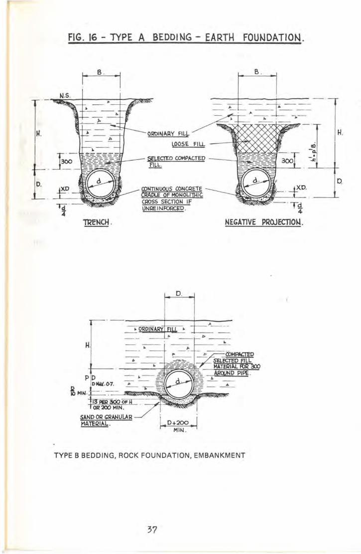
FIG. 16 - TYPE A BEDDING - EARTH FOU~DATION.
'TRENCH. NEGATIVE
D.
•-:c:
B.
- --- 1;. A _
--", -.--- --
II-t
I-- -
SELECf£O COMPACTED -_~~~fILL.
CONTINUOUS CONCREiECAAOLE OF MOIJOUJHICC~SS SECTION IFUNQE INFOr<CED .
8.1-
~.
o.
D.
. .1.. 0 -4-200 .~
MIN.
1'_--
TYPE B BEDDING, ROCK FOUNDATION, EMBANKMENT
37

FIG. 11 - TYPE B BEDDING - ROCK FOUNDATION.
. .' T ______~D+ 200 I\~PER 300 OFH
MIN .... OR 2OJMIN.
--~
.- ---
A' ·OROIIolARY FILL - t...>ct><Y~)Q<t~~
LOOSE. FILL ---*OOK>~X>d
CDMPACTED SAND O~GRANULAR MATERIAL.
~=:a+--- SELECTED COfolPACTED ~---t:~FILL.
B.
--b
. .\..0+20:1 I
MI~ . ..
D.
H.
~'-'13 PER 300 OF HOR 200 MIN .
TRENCH. NEGATIVE PROJ ECnON.
D.
b----
I
i. 0+200 ... 1MIN.
..•. :-r:=-:--- - - _.
~:.;::l~~-IoI-LI~.:.:...P-1 _
H
SAND OR ~RANlJlAR
MATERIAL.
EMBANKMENT
38

FIG. 18 - TYPE B BEDDI NG - EARTH fOUNDATION.
H.
D.
H.
po.
B.
!lI- ~- =1---- J. -- -- -,a-
0",,"""" ell~-.- ~-' -=-;~S JLOOSE FI LL aJ
COMPACTED SAt-ID ORGIW4UlAR MAT£RIAL'25 MII-l. ll-l1Q(l-,lESS.
. .
~.G;O·_I
ijECATIVE PROJECTION.
D.
/>.-- ---- -1>_--
Ij ..D+kJO -I
MIN.
H
o
TYPE C BEDDING, ROCK FOUNDATION, EMBANKMENT
39

FIG. 19 - TYPE C BEDDING - ROCK FOUNDATION.
B. B.
D.
H.
_II-C
Q5
-----tJ.5-'- .
150
I·······..:·····.·~I \)-+ '200~ G PER 300 OF H
.. MIN. ISO MIN.
SEl.CQl:D COMPACTED -----E.:::::=.FILL.
CDMPACTED Sb.t-JD OQ'RANUlAR MA1ERIAL.
TRENCH. ~EGATIVE PROJECTION.
PDDiO ~ I~ .-----=
+--
~~DOR:=LARMATERIAL
b PER 300 OF HOR ISO MIN.
EMBANKMENT
40

FIG. 20 - TYPE C BEDDI NG - EARTH FOUNDATION.
B. B.
lOOSE FILL _--{ffl;;~tX~>(;
SELECTED COMPACJ1:0FILL.
12'50~
t-JEGATIVE PROJECTION.
H
o.
D.
-. - ----+----+---:-1>---O~DINARY-rFi{C--~ -.----- ---- -- ~--·--1-1>- -- --,- -- --/>
AH
TOOM'N...-·- ,
SAND OR GRANULAQMATERIAL..
PD.
TYPE D BEDDING, ROCK FOUNDATION, EMBANKMENT
41

FIG. 21 - TYPE 0 BEDDI NG - ROCK FOUNDAT\ON.
B.
N.S.l>
J>
H ~
1>_._--
~
D. DiO COMPACTED 6AND OR
GRAtJULAR MAlCRIAL
TRENCI-l.
D.
NEGATIVE PROJECTION.
•4:
H.
D.
_. - ----+----+---.--OIlDiNARV FILL. ~
H.-- --
A
- -b'==I=~_
PD.
IOOHIN.
~~OORG~U::-~MATERIAL.
EMBANKMENT
/>...- --
42

FIG. 22 - TYPE O. BEDDING - EARTH FOUNDAT\ON.
J.l.
D.
B.
N.5.
ORDINARYFILL
LOOSE FilL -~~~)C)C
"-....c:
H.
D.
TREWCH.
o.
NEGAllVE PROJECnOt-J.
H.
PD.
b
b I> I~Allf FILLl> b
_--'-'- I>
.. .!'-+b-3~=-=-~-- =E -~-i=--0-
~~~Gi:~~. -- :r/~&W»'~~_A\-W»
EMBANKMENT
43

44
7.02 Pipe Testing LoadThe test load for various diameters and classifications of pipe are specified in A.S.A 1342-1973. The method of testing, "two edged" or "three edged" bearing, islikewise specified in that Standard Specification. Table 2 is an extract indicatingthe test loads.
7.03 Load Factors (Ft)
The ability of a pipe to withstand the calculated load depends not only on itsinherent strength but also on the distribution of the vertical load (beddingreaction) and on the lateral support acting against the sides of the pipe (backfillreaction). The load factor is that factor used in the translation of the calculatedsite loading to the equLvalent test load. This factor therefore varies with the typeof load, the bedding and side support conditions.
The test load that a pipe must sustain therefore is the sum of the variouscalculated site loads divided by the appropriate load factor in each case, i.e.:
TEST LOAD = Ww We Wc and/or Wu-+-+- -Ft1 Ft2 Ft3 Ft4
Extreme care should be taken when selecting the load factor in calculation andsimilar care should be exercised, on site, in attaining the installation conditionapplicable to that load factor. After all, such care is exercised in the design andconstruction of high rise buildings.
The load factor appropriate to the type of bedding and installation condition canbe selected from the following tables:-

TYPE A BEDDING - ROCK FOUNDATION
TRENCH EMBANKMENT
RATIO X LOAD p::; 0.75FACTOR
rs::;+1.01Ft HID rs ::; -1.0
LOAD FACTOR Fe
0.1 1.7 0.5 6.5 50.2 2.6 1.0 4.8 50.3 3.6 1.5 4.3 5O.ll 4.7 2.0 4.0 5
3.0 3.8 55.0 3.8 5,
10.0 3.7 5'
TYPE A BEDDING - EARTH FOUNDATION
TRENCH EMBANKMENT
CLASS RATIO X p::; 0.75OF
PIPE 1/4 1/6 rsHID
S 3 2.6 0.7-1.0 -0.5X 3 2.6Y 2.6 2.25 LOAD FACTOR FeZ 2.2 1.9
0.5 6.5 5Ratio X represents the 1.0 4.8 5concrete cradle depth 1.5 4.3 5as a proportion of 2.0 4.0 5D - the outside 3.0 3.8 5diameter of the pipe. 5.0 3.8 5
10.0 3.7 5
NOTE:Trench Condition includes negative projection conditions -negative (-) settlement ratio.
Embankment Condition includes wide trench, positive projectionand imperfect trench conditions - positive (+) settlement ratio.
Ft for concentrated superimposed loads is 1.5 irrespective of thepipe installation conditions.
45

46
TYPE B BEDDING - ROCK FOUNDATION
TRENCH EMBANKMENT
BACKFILL LOAD p = 0.7 p = 0.5COMPACTION FACTOR
Ft HID rs rs
~ 90% 2.5 +1.0 -1.0 +1.0 -1.0< 90% 1.9
LOAD FACTOR Fe
NOTE: 0.5 2.8 2.9 2.3 2.7rs =Settlement ratio 1.0 2.5 2.9 2.3 2.7p = Projection ratio 1.5 2.4 2.9 2.2 2.7
2.0 2.4 2.9 2.2 2.73.0 2.3 2.9 2.2 2.76.0 2.3 2.9 2.2 2.7
10.0 2.3 2.9 2.2 2.7
TYPE B BEDDING - EARTH FOUNDATION
TRENCH EMBANKMENT
BACKFI LL LOAD p = 0.7 p = 0.5COMPACTION FACTOR
Ft HID rs rs
~ 90% 2.5 +0.5 +0.5< 90% 1.9 to -0.5 to -0.5
+0.8 +0.8
0.5 2.8 2.9 2.3 2.71.0 2.5 2.9 2.3 2.71.5 2.4 2.9 2.3 2.72.0 2.4 2.9 2.3 2.73.0 2.3 2.9 2.3 2.75.0 2.3 2.9 2.3 2.7
10.0 2.3 2.9 2.3 2.7
NOTE:Trench Condition includes negative projection conditions -negative (-) settlement ratio.
Embankment Condition includes wide trench, positive projectionand imperfect trench conditions positive (+) settlement ratio.
Ft for a concentrated superimposed load is 1.5 irrespective of pipeinstallation condition.

TYPE C BEDDING - ROCK FOUNDATION
TRENCH EMBANKMENT
BACKFILL Ftp = 0.9 p = 0.7 I p = 0.5
COMPACTIONHID rs
~ 90% 1.9< 90% 1.5 +1.0 -1.0 +1.0 -1.0 +1.0 -1.0
LOAD FACTOR Fe
rs is the settlement 0.5 2.8 2.5 2.2 2.3 1.9 2.1ratio. 1.0 2.3 2.5 2.0 2.3 1.9 2.1
1.5 2.3 2.5 2.0 2.3 1.8 2.1p is the projection. 2.0 2.1 2.5 1.9 2.3 1.8 2.1
3.0 2.0 -2.5 1.9 2.3 1.8 '2.15.0 2.0 2.5 1.9 2.3 1.8 2.1
10.0 2.0 2.5 1.9 2.3 1.8 2.1
TYPE C BEDDING - EARTH FOUNDATION
TRENCH EMBANKMENT
BACKFILLFt
p = 0.9 p = 0.7 I p=O.5COMPACTION HID
rs
~ 90% 1.9 +0.5 +0.5 +0.5< 90% 1.5 to -0.5 to -0.5 to -0.5
+0.8 +0.8 +0.8-
LOAD FACTOR Fe
0.5 2.8 2.5 2.2 2.3 1.9 2.11.0 2.3 2.5 2.0 2.3 1.9 2.11.5 2.3 2.5 2.0 2.3 1.8 2.12.0 2.1 2.5 1.9 2.3 1.8 2.13.0 2.0 2.5 1.9 2.3 1.8 2.15.0 2.0 2.5 1.9 2.3 1.8 ~.1
10.0 2.0 2.5 1.9 2.3 1.8 2.1
NOTE:Trench Condition includes negative projection conditions - negative (-)settlement ratio.
Embankment Condition includes wide trench, positive projection andimperfect trench conditions - positive (+) settlement ratio.
Ft for a concentrated superimposed load is 1.5 irrespective of pipeinstallation condition.
47

48
TYPE D BEDDING - ROCK FOUNDATIONEARTH FOUNDATION
TRENCH EMBANKMENT
BACKFILLFt
p =0.9 p =0.7 p =0.5COMPACTION HID
rs (rock foundation)** 1.1
+1.0 -1.0 +1.0 -1.0 +1.0 -1.0
**no special attempt LOAD FACTOR Femade to selectand compact fill 0.5 1.4 1.4 1.3 1.3 1.2 1.2material. 1.0 1.3 1.4 1.2 1.3 1.2 1.2
1.5 1.3 1.4 1.2 1.3 1.1 1.2rs is the settlement 2.0 1.2 1.4 1.2 1.3 1.1 1.2ratio. 3.0 1.2 1.4 1.2 1.3 1.1 1.2
5.0 1.2 1.4 1.2 1.3 1.1 1.2P is the projection 10.0 1.2 1.4 1.2 1.3 1.1 1.2ratio.
+0.5 +0.5 +0.5HID to -0.5 to -0.5 to -0.5
+0.8 +0.8 +0.8
rs (earth foundation)
p =0.9 p =0.7 p =0.5
NOTE:Trench Condition includes negative projection conditions.
Embankment Condition includes wide trench, positive projection andimperfect trench.
Ft for concentrated superimposed loads is 1.1. Allowance must be madefor water load.
7.04 Settlement Ratio
Settlement Ratio (rs) is a semi-empirical abstract mathematical ratio which takesinto consideration:-
(1) Settlement of the pipe into its foundation.
(2) Deformation of the pipe.
(3) Settlement of the natural ground adjacent to the pipe.
(4) Compression of the columns of soil adjacent to the pipe etc.
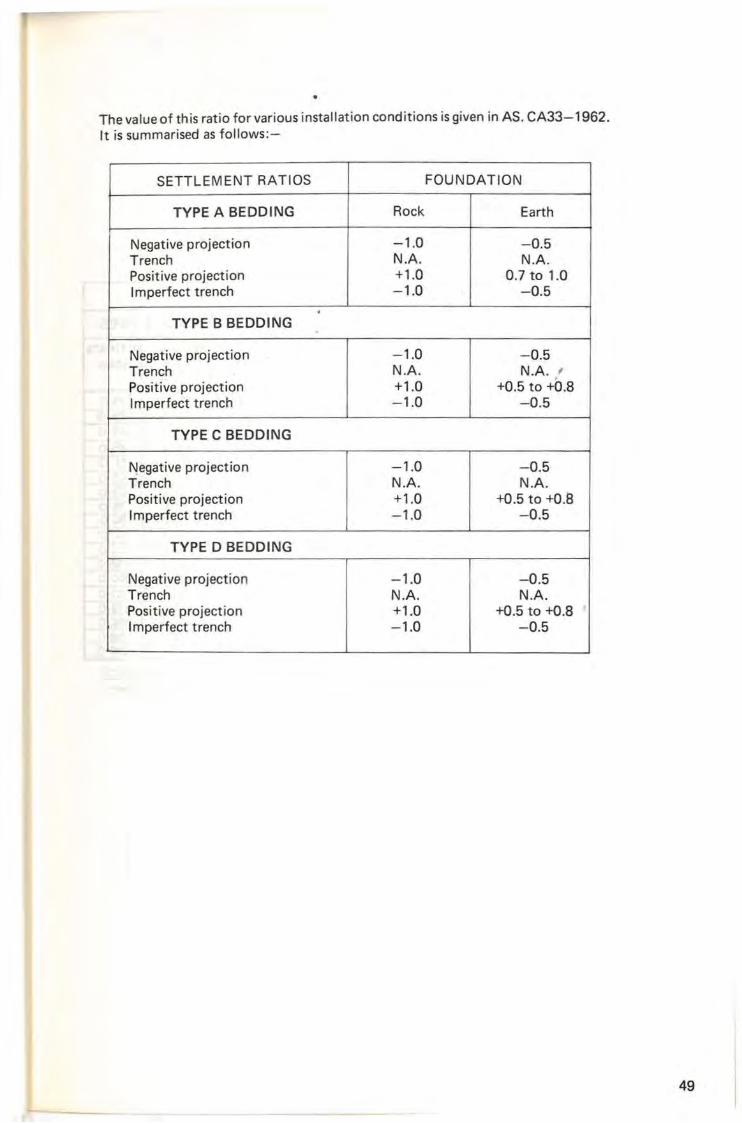
The value of this ratio for various installation conditions is given in AS. CA33-1962.It is summarised as follows:-
SETTLEMENT RATIOS FOUNDATION
TYPE A BEDDING Rock Earth
Negative projection -1.0 -0.5Trench N.A. N.A.Positive projection +1.0 0.7 to 1.0Imperfect trench -1.0 -0.5.
TYPE B BEDDING
Negative projection -1.0 -0.5Trench N.A. N.A. ,Positive projection +1.0 +0.5 to +0.8Imperfect trench -1.0 -0.5
TYPE C BEDDING
~egative projection -1.0 -0.5Trench N.A. N.A.Positive projection +1.0 +0.5 to +0.8Imperfect trench -1.0 -0.5
TYPE D BEDDING
Negative projection -1.0 -0.5Trench N.A. N.A.Positive projection +1.0 +0.5 to +0.8Imperfect trench -1.0 -0.5
49

FIG. 23. - CHASE OUT FOUNDATiONFOR SOCKETS
METRIC TABLE FOR PIPE TEST LOADS
AS TABLE 2.
TEST LOAD (WOTE I) kNjm.
~OMINAL CLASS S PIPES CLASS X PIPES CLASS Y PI PES CLASS Z PIPES
SiZE CRAC.KING UlTIMATE CRACKING ULTIMATE CRACKIIIIG lJLTI MATE. CRACK.ING UL.TI MATELOAD LOAD LOAD LOAD LOAD WAD WAD LO/l.D
(~on: 2) (NOTE 2) (NOTE 2) (NOTE 2)
100 10·0 1'5-0 13·0 19·5 19·; 29·5 2"0 39·0ISO 10·0 15·0 13·0 19·5 19·5 29·5 2(,,0 39·0225 fl·O lG·5 14·0 2/·0 21·0 31·5 28·0 4'2·0
300 12·0 J8·0 15·0 22·5 22·5 34·0 30·0 45·0375 13·0 19·5 17·0 25·5 25·5 38·5 3+·0 51·0450 15·0 22·5 ::;0·0 30·0 30·0 45·0 40·0 '0'0525 17·0 25·5 :23·0 34·5 34·5 52·0 4',,0 b9·0fIX) 19·0 '28·5 x,·0 39·0 39·0 58·5 52·0 78·0750 21·0 3\·5 32·0 48·0 48·0 n·o G4·0 9G·O900 23·0 34·5 37·0 55'5 55·5 83·5 74·0 11/·0
1050 25·0 37·5 42·0 "3'0 <;;3·0 94·5 84·0 12',01'200 27·0 40·5 4'·0 G9·0 G9·Q 103·5 92·0 1'38·01'350 29·0 43·5 50·0 75·0 75·0 112·5 100·0 150·01500 31·0 4{'·5 54·0 81·0 81·0 121·5 108'0 Ibl·OIlO5O 33·0 49·5 58·0 ~7·0 67·0 130·5 11"·0 174·01BOO 35·0 52·5 '2·0 93·0 93·0 139·5 124·0 IBb·O1950 37·0 55·5 Q;.Q 99·9 99·0 148·5 132·0 198-02100 39·0 58·5 70·0 105·0 j05·0 157-5 140·0 210·0
I. THE TEST LOAD FOR A PIPE OF INTERMEDIATE. srZE CA~ BE DETERMI~ED BY STRAIGI4T-LINE INTEQPOLATION.
2. RJR MINIMUM CLEAR COVE.R OF IOmm.- 0·15 Mm. CRACK j OlER IOmm.UP 10 AND fNCWDINC, 2OmM.- O·20M"'.
CRA<:~j O'iER 2Omm.-O·25mm.CRACK.
MARSTON + SCHLICK + SPANGLEREXPERIME~TAiIO'"
I IeQU"110~S LOAD FACTORSTO CALCULATE LOAD iRMJ5MISSI0~ O~ VARIOJS CO~[)ITlONSINST.ULED PIPE-VARIOUS COIoJDIllONS
I I
REQUIREDI LOAD TABLES I TEST LOAD.
ASA 1342 - 1973I
SELE (TIOI\l OF PIPE.
CLASSI FICATION
50

8 SELECTION OF PIPE FOR INSTALLATION
Having chosen the installation condition, the type of bedding (and backfill),having further calculated the loads transmitted to the pipe when it is installed(ensuring construction loads are not critical) and having divided each of theseloads by an appropriate load factor it. is then possible to add the modified loadstogether to obtain the test load that the required pipe must sustain.
By using Table 2 it is possible to select the classification of pipe suitable for thatinstallation.
9 OTHER LOADS SUSTAINED BY THE PIPEThermal and moisture changes in the pipeline, differential settlement, subsidenceor other soil movement, uneven support in the bedding or in the foundation allcan induce additional stresses in the pipe or its joint.
However, by making the joints flexible and thereby providing a means by whichindividual pipes can move axially these tresses can be largely eliminated. Theremaining stresses in rigid pipelines can be reduced I1Y proper care in, andsupervision of, the site installation.
It should be recognised that if the full benefit of the bedding is to be achieved,the bottom of the trench or embankment must be stable.
10 ECONOMIES IN PROVISION OF TRENCHThe effective width of a trench is that dimension at the top of the pipe. Inundeveloped subdivisions or in open country it is often more economical to slopethe sides of the trench from a plane 30 cm above the top of the pipe to theground surface. This method is dependent upon the angle of repose of the naturalsoil and local safety regulations, but it eliminates the placing, maintaining andremoval of substantial amounts of sheeting and bracing.
11 TRENCH EXCAVATIONAs in any other earth moving operations there is a'Iot of money to be made orlost as a result of selecting the correct equipment for the job. The choice willdepend on the'material to be excavated, the depth and width of the trench, theamount of space available for the storage of excavated material and for theoperation of the equipment and the availability of the equipment itself.
11.01 Trenching MachinesIn relatively shallow (4-5 m) and narrow trenches (up to 800 mm) in cohesivesoils trenching machines can make good progress at low cost. They are seldomused and not readily available.
51

11.02 BackhoesBackhoes are satisfactory for excavating loose rock in trench widths exceeding0.7 m and depths up to 8 m. Bucket sizes varying from l4 cubic metre to 1Y2 metreare common. This larger size however cannot be used for trenches narrower than1300 mm. The backhoe can be used to handle the pipe, with a belly sling, into thetrench. Where trench side support is not required this method is generally veryeconomical. When sheet piling is required a crane can be used to handle the pipelaying operation.
11.03 ClamshellsClamshells are generally used when a vertical lift only is possible due to constraintson site.
11.04 Draglines
In deep excavations, in two stages, in open country the feasibility of using adragline to excavate the top part of the excavation should be examined. Thelower level may be operated with a backhoe, rotating to drop its spoil forcollection by the dragline to complete the excavation cycle.
12 TRENCH WIDTHS - COMPACTION EQUIPMENTTrench widths must be kept to a minimum to reduce the load on the pipe.However, in the larger sized pipes particularly they must be of sufficient width topermit the use of compaction equipment such as wacker plates, footpath rollersetc., if the required density is to be achieved.
13 METHODS OF COMPACTIONThe methods and equipment used in placing backfill must be selected with care toprevent damage to or dislocation of the pipeline. Fill should be brought up evenlyeither side of the pipe.
13.01 Cohesive MaterialsCohesive materials are not recommended because of the small range of moistureover whi'ch they can be compacted satisfactorily. However, if there is little choiceand approval has been granted for their use, strong pressure will be required to beexerted by impact type equipment on the material, at its optimum moisturecontent and in controlled layers.
In confined areas pneumatic tampers may do a reasonable job. In the upper partof the trench, where sufficient width exists, vibratory sheepsfoot rollers may beused if enough cushion of fill has been provided over the pipe for its protection.
13.02 Cohesion less Materials
Cohesion less materials have high internal friction values, between the particles,which have to be reduced by reorientation. This is best achieved by the use ofvibratory equipment.
In sand, saturation with water and the use of immersion vibrators will giveuniform compaction. Care should be taken to ensure that the water used in thismethod, or as a result of "puddle filling", can be drained off. A permanent threemetre length of subsoil drain should be provided upstream from each pit,headwall or other structure, sealed at its upstream extremity and capable ofdischarging through the wall of the structure at the other end.
52

13.03 Imported BackfillCare should be taken when considering the importation of backfill that it doesnot radically alter natural ground water movement. Cohesive material couldprovide a good dam and sand an excellent drainage condition.
14 LAY "TOP UP'Elliptically reinforced pipes must be laid the right way up.
15 STRUTTINGLarger pipes with higher levels of fill should be strutted internally whilst the fill isbeing applied. Continuous timbers should be placed along the invert and crown ofthe pipe and the strutting placed vertically between them.
16 Although a concrete pipe is robust it should be sensibly handled to avoid damage.
17 OMISSIONSLittle has been said in this paper about the economics of operating the varioustypes of equipment and no detail has been given on the subjects of tunnelling,jacking, ocean outfalls, railway or aircraft loadings. However, references have beengiven in the appendix which are recommended for further reading on these topics.
18
18.01
18.02
18.03
19
CONCLUDING COMMENTS
The supporting strength of a pipe is dependent upon its class and the trenchwidth, bedding, side and backfill conditions under which it is installed.
Serious consideration must be given to the construction loads applied to the pipewhilst the project is in progress.
Both designer and contractor must be aware of the constraints each has placed onthe job, to ensure that project becomes a successful investment for the owner.
ACKNOWLEDGEMENT
Much of the detailed information contained in this paper has been derived fromthe Austral ian Standard pubIication "CA 33-1962" for "Concrete Pipe LayingDesign" and the "Concrete Pipe Installation Manual" (American Concrete PipeAssociation) .
53

54
APPENDIX TO "INSTALLATION OFREINFORCED CONCRETE PIPES"by Nigel D. Knowles
FACTS OF SIGNIFICANCE
Support SupportEffect
Bedding Diam. Trench NarrowType I'Z'I Width
FillEmbankment Fill
Height Heightto
(Earth) Class (mm) Wide(m) (m)Trench
B 1800 2400 10.8 Embankment 5 54%
D 1800 2400 3.5 Embankment 2.9 17%
Effect of Bedding Type on 68% 42%Load Support Capacity
BIBLIOGRAPHY
1. "MANUAL AND REPORTS ON ENGINEER PRACTICE No. 37"American Society of Civil Engineers.
2. "CONSTRUCTION PLANNING, EQUIPMENT AND METHODS" - ByPeurifoy, Published McGraw-Hili, Engineering Series.
3. "CONCRETE PIPE HANDBOOK" - American Concrete Pipe Association.
4. "CONCRETE PIPE DESIGN MANUAL" - American Concrete PipeAssociation.
5. "PIPE JACKING IN LIEU OF TUNNELLING" - A Paper Presented byR. Surgeoner, During National Seminar 1972, "Concrete Pipe ... as Modernas Tomorrow" - Concrete Pipe Association of Australia.
6. "LOADING CHARTS FOR DESIGN OF BURIED RIGID PIPES" National Building Studies, Special Report 37, Her Majesty's StationeryOffice, London.
7. Australian Standard CA33-1962 "CONCRETE PIPE LAYING DESIGN".
8. Australian Standard 1342-1973 "PRECAST CONCRETE DRAINAGEPIPES".