concrete & highway materials laboratory sem concrete lab manual.pdf · vee- bee test hardened...
TRANSCRIPT

QMP 7.1 D/F
Channabasaveshwara Institute of Technology (An ISO 9001:2015 Certified Institution)
NH 206 (B.H. Road), Gubbi, Tumkur – 572 216.Karnataka.
Department of Civil Engineering
Concrete & Highway Materials Laboratory
10CVL78
B.E - VII Semester
Laboratory Manual 2017-18
Name: ____________________________________
USN: ____________________________________
Batch: ________________ Section: ____________

QMP 7.5/RC-1 Rev.1
Channabasaveshwara Institute of Technology (An ISO 9001:2015 Certified Institution)
NH 206 (B.H. Road), Gubbi, Tumkur – 572 216.Karnataka.
Department of Civil Engineering
Concrete & Highway Materials Laboratory
10CVL78
August 2017
Prepared by: Reviewed by:
Ajith Kumar R Dr. Sudhi Kumar G S
Asst. Professor Professor
Approved by:
Dr. Sudhi Kumar G S
Professor & Head
Dept. of Civil Engg.

Channabasaveshwara Institute of Technology (An ISO 9001:2015 Certified Institution)
NH 206 (B.H. Road), Gubbi, Tumkur – 572 216.Karnataka.
SYLLABUS
Subject code : 10CVL78 IA Marks : 25
No. of Practical Hours : 03 Exam Hours : 03
Total No of Practical Hours : 42 Exam Marks : 50
PART - A
CEMENT:
Normal Consistency of cement
Setting time of cement
Soundness by Autoclave method
Compression strength test
Air permeability test of cement for fineness
Specific gravity of cement.
FRESH CONCRETE:
Workability – slump test
Compaction factor test
Vee- Bee test
HARDENED CONCRETE:
Compression strength
Split tensile test
PART - B SOIL:
Density of Soil by Sand replacement method
CBR test
AGGREGATES:
Crushing test
Abrasion test
Impact test
Shape tests (Flaky, Elongation, and Angularity number)
Specific gravity BITUMINOUS MATERIALS AND MIXES:
Specific Gravity
Penetration test
Ductility test
Softening point of bitumen.
Flash and fire point
Viscosity
Marshall Stability test

INDEX PAGEINDEX PAGEINDEX PAGEINDEX PAGE Note:
• Note: If the student fails to attend the regular lab, the experiment has
to be completed in the same week. Then the manual/observation and
record will be evaluated for 50% of maximum marks.
Sl.No
Name of the Experiment
Date
Manual Marks
(Max . 25)
Record Marks
(Max. 10)
Signature
(Student)
Signature
(Faculty)
Conduction Repetition Submission of Record
Average

Channabasaveshwara Institute of Technology (ISO 9001:2015 Certified Institution)
NH 206 (B.H. Road), Gubbi, Tumkur – 572 216. Karnataka
DEPARTMENT OF CIVIL ENGINEERING
Course objectives
• The objective of concrete laboratory is to determine the physical properties of
building construction materials like cement, fine and coarse aggregate. The tests
include determination of specific gravity, fineness, normal consistency, setting times,
workability and soundness of cement, fineness modulus of fine and coarse aggregate,
strength of cement mortar, cement concrete. Students can design the mix, make the
specimens and test the same for their respective strengths.
• The objective of highway materials laboratory is to determine some of the properties
of coarse aggregates and bitumen. Experiments include tests for impact, abrasion and
crushing strength for coarse aggregates. For bitumen, tests include penetration,
ductility, viscosity, softening point and flash and fire point. The students will be able
to infer the suitability of these materials for construction of road. This laboratory
course will help the students to understand the theoretical concepts learned in the
course transportation engineering
Course outcome
• Students at the end of the course will be able to test all the concrete materials as per IS
code, design of the concrete mix using IS code, determine the properties of fresh and
hardened concrete, measure the physical properties of the bitumen.

‘Instructions to the Candidates’
1. Students should come with thorough preparation for the experiment
to be conducted.
2. Students will not be permitted to attend the laboratory unless they
bring the practical record fully completed in all respects pertaining
to the experiment conducted in the previous class.
3. All the calculations should be made in the observation book.
Specimen calculations for one set of readings have to be shown in the
practical record.
4. Wherever graphs are to be drawn, A-4 size graphs only should be
used and the same should be firmly attached to the practical record.
5. Practical record should be neatly maintained.
6. They should obtain the signature of the staff-in-charge in the
observation book after completing each experiment.
7. Theory regarding each experiment should be written in the practical
record before procedure in your own words.

Channabasaveshwara Institute of Technology
(ISO 9001:2015 Certified Institution)
NH 206 (B.H. Road), Gubbi, Tumkur – 572 216. Karnataka
DEPARTMENT OF CIVIL ENGINEERING
CONTENTS
Sl No Title of the Experiment Page No
1 TEST ON CEMENT -
a) Standard Consistency 1-4
b) Setting Time Test on Cement 5-8
c) Specific Gravity of Cement 9-12
d) Soundness of Cement 13-16
e) Compression strength Test 17-22
2 TEST ON FRESH CONCRETE –
a) Slump Test 23-26
b) Compaction Factor Test 27-30
c) Vee Bee Test 31-33
3 TEST ON HARDENED CONCRETE –
a) Compression strength Test 34-36
b) Split Tensile Test 37-40
4 TEST ON AGGREGATES –
a) Impact Test 41-46
b) Crushing Test 47-52
c) Abrasion Test (Los Angeles Abrasion) 53-58
d) Shape Test 59-64
5 TEST ON BITUMEN –
a) Penetration Test 65-70
b) Ductility Test 71-76
c) Softening Point Test 77-82
d) Flash And Fire Point Test 83-86
e) Viscosity Test 87-90
f) Marshall Stability Test 91-94
g) Specific Gravity Test 95-97
6 TEST ON SOIL –
a) Density Of Soil By Sand Replacement Method 98-101
b) California Bearing Ratio Test 102-108

Concrete & Highway Materials Laboratory 10CVL-78 2017-18
Dept of Civil Engg, CIT Gubbi Page 1
VICAT APPARATUS
OBSERVATIONS:
S. No Weight of cement
taken in gms
(a)
Weight of water
taken in gms
(b)
Plunger
penetration
(mm)
Consistency of
cement in % by
weight b/a * 100

Concrete & Highway Materials Laboratory 10CVL-78 2017-18
Dept of Civil Engg, CIT Gubbi Page 2
Exp No: Date: NORMAL CONSISTENCY OF CEMENT
AIM: To determine the quantity of water required to produce a cement paste of standard
consistency.
APPARATUS:Vicat apparatus (conforming to IS: 5513 - 1976) with plunger (10 mm in
diameter) balance, weights, gauging trowel.
THEORY: The standard consistency of a cement paste is defined as that consistency which
will permit the vicat plunger to penetrate to a point 5 to 7 mm from the bottom of the
vicatmould. For finding out initial setting time, final setting time, soundness of cement and
compressive strength of cement, it is necessary to fix the quantity of water to be mixed in
cement in each case. This experiment is intended to find out the quantity of water to be mixed
for a given cement to give a cement paste of normal consistency and can be done with the help
of vicat apparatus.
PROCEDURE:
1. Prepare a paste of weighed quantity of cement (300 grams) with a weighed quantity of
potable or distilled water, starting with 26% water of 300g of cement.
2. Take care that the time of gauging is not less than 3 minutes, not more than 5 minutes and
thegauging shall be completed before setting occurs.
3. The gauging time shall be counted from the time of adding the water to the dry cement
untilcommencing to fill the mould.
4. Fill the vicatmould with this paste, the mould resting upon a non porous plate.
5. After completely filling the mould, trim off the surface of the paste, making it in level with
the top of the mould. The mould may slightly be shaken to expel the air.
6. Place the test block with the mould, together with the non-porous resting plate, under the
rod bearing the plunger (10mm diameter), lower the plunger gently to touch the surface of
the test block and quickly release, allowing it to penetrate into the paste.
7. This operation shall be carried out immediately after filling the mould.

Concrete & Highway Materials Laboratory 10CVL-78 2017-18
Dept of Civil Engg, CIT Gubbi Page 3

Concrete & Highway Materials Laboratory 10CVL-78 2017-18
Dept of Civil Engg, CIT Gubbi Page 4
8. Prepare trial pastes with varying percentages of water and test as described above until the
amount of water necessary for making the standard consistency as defined above is
obtained
9. Express the amount of water as a percentage by weight of the dry cement.
PRECAUTIONS:
Clean appliances shall be used for gauging. In filling the mould the operator hands and the blade
of the gauging trowel shall alone be used. The temperature of cement, water and that of test
room, at the time when the above operations are being performed, shall be 27 + 2�
C. For each
repetition of the experiment fresh cement is to be taken.
RESULT: Normal consistency for the given sample of cement is………………….. COMMENTS:

Concrete & Highway Materials Laboratory 10CVL-78 2017-18
Dept of Civil Engg, CIT Gubbi Page 5

Concrete & Highway Materials Laboratory 10CVL-78 2017-18
Dept of Civil Engg, CIT Gubbi Page 6
Exp No: Date
INITIAL AND FINAL SETTING TIMES OF CEMENT
AIM: To determine the initial and final setting times for the given sample of cement. APPARATUS:Vicat apparatus (conforming to IS: 5513-1976) with attachments, balance,
weights, gauging trowel.
INTRODUCTION: In actual construction dealing with cement, mortar or concrete, certain time
is required for mixing, transporting and placing. During this time cement paste, mortar, or
concrete should be in plastic condition. The time interval for which the cement products remain
in plastic condition is known as the setting time. Initial setting time is regarded as the time
elapsed between the moments that the water is added to the cement to the time that the paste
starts losing its plasticity. The final setting time is the time elapsed between the moment the
water is added to the cement, and the time when the paste has completely lost its plasticity and
has attained sufficient firmness to resist certain pressure. The constituents and fineness of cement
is maintained in such a way that the concrete remains in plastic condition for certain minimum
time. Once the concrete is placed in the final position, compacted and finished it should lose its
plasticity in the earliest possible time so that it is least vulnerable to damages from external
destructive agencies. This time should not be more than 10 hours which is referred to as final
setting time. Initial setting time should not be less than 30 minutes.
PROCEDURE:
Preparation of Test Block:
1. Prepare a neat cement paste by gauging 300 grams of cement with 0.85 times the water
required to give a paste of standard consistency.
2. Potable or distilled water shall be used in preparing the paste.
3. The paste shall be gauged in the manner and under the conditions prescribed in determination
of consistency of standard cement paste.
4. Start a stop-watch at the instant when water is added to the cement.
5. Fill the mould with the cement paste gauged as above the mould resting on a nonporous plate.
6.Fill the mould completely and smooth off the surface of the paste making it level with the
top of the mould. The cement block thus prepared in the mould is the test block

Concrete & Highway Materials Laboratory 10CVL-78 2017-18
Dept of Civil Engg, CIT Gubbi Page 7
OBSERVATIONS
Time in minutes
Height in mm fails to
penetrate
DETERMINATION OF INITIAL SETTING TIME:

Concrete & Highway Materials Laboratory 10CVL-78 2017-18
Dept of Civil Engg, CIT Gubbi Page 8
1. Place the test blocks confined in the mould and rest it on the non-porous plate, under the
rod bearing initial setting needle, lower the needle gently in contact with the surface of
the test block and quickly release, allowing it to penetrate into the test block.
2. In the beginning, the needle will completely pierce the test block.
3. Repeat this procedure until the needle, when brought in contact with the test block and
released as described above, fails to pierce the block to a point 5 to 7 mm measured from
the bottom of the mould shall be the initial setting time.
DETERMINATION OF FINAL SETTING TIME:
1. Replace the needle of the Vicat apparatus by the needle with an annular attachment.
2. The cement shall be considered as finally set when, upon applying the needle gently to the
surface of the test block, the needle makes an impression there on, while the attachment fails
to do so.
3. The period elapsed between the time when water is added to the cement and the time at which
the needle makes an impression on the surface of test block while the attachment fails to do so
shall be the final setting time.
PRECAUTIONS: Clean appliances shall be used for gauging. All the apparatus shall be free
from vibration during the test. The temperature of water and that of the test room, at the time of
gauging shall be 27�C + 2�C. Care shall be taken to keep the needle straight.
RESULT: Initial setting time for the given sample of cement =
Final setting time for the given sample of cement =
COMMENTS:

Concrete & Highway Materials Laboratory 10CVL-78 2017-18
Dept of Civil Engg, CIT Gubbi Page 9
Specific Gravity Bottle
OBSERVATIONS
Description of item Trial 1 Trial 2 Trial 3
Weight of empty bottle
W1 g
Weight of bottle + Cement
W2 g
Weight of bottle + Cement +
Kerosene W3 g
Weight of bottle + Full
Kerosene W4 g
Weight of bottle + Full Water
W5 g
Specific gravity of Kerosene Sk = W4 - W1 / W5 - W1…………………
Specific gravity of Cement Sc = W2 - W1 / ((W4 - W1)-(W3-W2))*Sk……………………….
Sc = (W2 - W1)* (W4 - W1) / ((W4 - W1)-(W3-W2))*(W5 - W1)……………………….

Concrete & Highway Materials Laboratory 10CVL-78 2017-18
Dept of Civil Engg, CIT Gubbi Page 10
Exp No: Date: SPECIFIC GRAVITY OF CEMENT
AIM: To determine the specific gravity of given sample of cement. APPARATUS: Physical balance, specific gravity bottle of 50ml capacity, cleans kerosene.
INTRODUCTION: Specific gravity is defined as the ratio between weight of a given volume
of material and weight of an equal volume of water. To determine the specific gravity of cement,
kerosene is used which does not react with cement.
PROCEDURE:
1. Clean and dry the specific gravity bottle and weigh it with the stopper (W1).
2. Fill the specific gravity bottle with cement sample at least half of the bottle and weigh with
stopper (W2).
3. Fill the specific gravity bottle containing the cement, with kerosene (free of water) placing the
stopper and weigh it (W3).
4. While doing the above do not allow any air bubbles to remain in the specific gravity bottle.
5. After weighing the bottle, the bottle shall be cleaned and dried again.
6. Then fill it with fresh kerosene and weigh it with stopper (W4).
7. Remove the kerosene from the bottle and fill it with full of water and weigh it with stopper
(W5).
8. All the above weighing should be done at the room temperature of 27 0C + 1
0C.
PRECAUTIONS
1. Only kerosene which is free of water shall be used.
2. At time of weighing the temperature of the apparatus will not be allowed to exceed the
specified temperature.
3. All air bubbles shall be eliminated in filling the apparatus and inserting the stopper.

Concrete & Highway Materials Laboratory 10CVL-78 2017-18
Dept of Civil Engg, CIT Gubbi Page 11

Concrete & Highway Materials Laboratory 10CVL-78 2017-18
Dept of Civil Engg, CIT Gubbi Page 12
4. Weighing shall be done quickly after filling the apparatus and shall be accurate to 0.1 mg.
5. Precautions shall be taken to prevent expansion and overflow of the contents resulting from
the heat of the hand when wiping the surface of the apparatus.
RESULT: Average specific gravity of given sample of cement = COMMENTS
.

Concrete & Highway Materials Laboratory 10CVL-78 2017-18
Dept of Civil Engg, CIT Gubbi Page 13
Autoclave Apparatus
OBSERVATION
Type of Cement Tested
Initial Length Of The Specimen L1
Final Length Of The Specimen L2
Expansion Of The Specimen (L1- L2 )
CALCULATION
Soundness of cement=L1-L2,
Where,
L1=Length measured after curing for a period of 24 hrs in a moist room.
L2=Length measured after completion of autoclave test.
A contraction (negative expansion) is indicated by prefixing a (–) sign to the percentage
expansion reported.

Concrete & Highway Materials Laboratory 10CVL-78 2017-18
Dept of Civil Engg, CIT Gubbi Page 14
Exp No: Date: SOUNDNESS OF CEMENT
AIM: To determine the soundness of the given sample of cement by "Autoclave" Method.
APPARATUS: Autoclave apparatus, Balance, Weights, Water bath. Measuring cylinder, Length comparator, Trowel
INTRODUCTIONIn the soundness test a specimen of hardened cement paste is boiled for a
fixed time so that any tendency to expand is speeded up and can be detected. Soundness means
the ability to resist volume expansion
PROCEDURE
1. Thinly cover the mould with mineral oil. Then attach the reference points so as to get an
effective length of 250 mm.
2. Take 500 g of cement and mix with sufficient water to give a paste of standard consistency.
3. After mixing fill the mould in one or two layers by pressing the paste into corners by thumb.
Smoothen the top layer by trowel.
4. After completion of preparation of the mould, store it in a moist room for a period of 24
hours.
5. After 24 ± ½ hrs after moulding, remove the specimen from the moist atmosphere, measure
its length (L1) and place it in the autoclave at room temperature in a rack so that the four
sides of each specimen is exposed to saturated steam vapour during the entire period of test.
6. To permit air to escape from the autoclave during the early portion of the heating period, left
the vent valve open until steam begins to escape.
7. Then close the vent valve and raise the temp of the autoclave at such a rate, so as to make the
gauge pressure of the steam to 2.1 N/mm2 in 1 to 1.5 hrs from the time heat turned on. This
pressure is maintained for 3 hrs.
8. After 3 hrs switch off the autoclave, and let it be cooled at the rate so as to make the pressure
less than 0.1 N/mm2 in one hour and bring it to atmospheric pressure by opening vent valve.
9. Then remove the specimen from autoclave and place it in water maintained at a temp of
9000C. Then cool the water to 27±2
0C in 15 minutes. Dry the surface of the specimen and
measure its length (L2).

Concrete & Highway Materials Laboratory 10CVL-78 2017-18
Dept of Civil Engg, CIT Gubbi Page 15

Concrete & Highway Materials Laboratory 10CVL-78 2017-18
Dept of Civil Engg, CIT Gubbi Page 16
Note: In the event of cement failing to comply with the specified requirements, a further test
should be made from another portion of the same sample in manner described above, but
after aeration (done by spreading out to a depth of 75 mm at a relative humidity of 50 to 80%
for a total period of 7 days)
RESULT: Expansion in mm
COMMENTS

Concrete & Highway Materials Laboratory 10CVL-78 2017-18
Dept of Civil Engg, CIT Gubbi Page 17
Compression Strength Machine
CALCULATION:
Calculate the compressive strength from the crushing load and the average area over
which the load is applied. Express the results in N/mm2 to the nearest 0.05 mm
2. Compressive
strength in N/mm2 = P/A =
Where P is the crushing load in Nand A is the area in mm2 (5000 mm
2)

Concrete & Highway Materials Laboratory 10CVL-78 2017-18
Dept of Civil Engg, CIT Gubbi Page 18
Exp No: Date:
COMPRESSIVE STRENGTH OF CEMENT
AIM: To determine the compressive strength of standard cement mortar cubes compacted by means of standard vibration machine.
APPARATUS: Vibration machine and cube moulds of size 7.06 cms (Conforming to IS: 4031 1988)
STANDARD SAND: The standard sand to be used in the test shall conform to IS: 650-1991 or
sand passing 100 percent through 2 mm sieve and retained 100 percent on 90 micron IS sieve. 2mm to 1mm 33.33 percent
1mm to 500 microns 33.33 percent
500mm to 90 microns 33.33 percent
INTRODUCTION: The compressive strength of cement mortars is determined in order to
verify whether the cement conforms to IS specifications and whether it will be able to develop
the required compressive strength of concrete. The average compressive strength of at least three
mortar cubes (area of the face 50 cm2 ) composed of one part of cement and three parts of
standard stand should satisfy IS code specifications.
PROCEDURE:
Mix proportions and mixing:
1. Clean appliances shall be used for mixing and the temperature of the water and that of the test
room at the time when the above operations are being performed shall be 270 + 2
0C.
2. Place in a container a mixture of cement and standard sand in the proportion of 1:3 by weight
mix it dry, with a trowel for one minute and then with water until the mixture is of uniform
color.
3. The quantity of water to be used shall be as specified below.
4. In any element, it should not take more than 4 minutes to obtain uniform colored mix.
5. If it exceeds 4 minutes the mixture shall be rejected and the operation repeated with a
fresh quantity of cement, sand and water.
6. The material for each cube shall be mixed separately and the quantity of cement standard
sand and water shall be as follows:

Concrete & Highway Materials Laboratory 10CVL-78 2017-18
Dept of Civil Engg, CIT Gubbi Page 19

Concrete & Highway Materials Laboratory 10CVL-78 2017-18
Dept of Civil Engg, CIT Gubbi Page 20
Cement 200grms
Standard sand 600 grms
Water (P/4 + 3.0) percent of combined weight of cement and sand, where p is the
percentage of water required to produce a paste of standard consistency.
MOULDING SPECIMENS:
1. In assembling the moulds ready for use, cover the joints between the halves of the
mouldwith a thin film of petroleum jelly and apply a similar coating of petroleum jelly
between the contact surfaces of the bottom of the mould and its base plate in order to
ensure that no water escapes during vibration.
2. Treat the interior faces of the mould with a thin coating of mould oil.
3. Place the assembled mould on the table of the vibration machine and firmly hold it is
position by means of suitable clamps.
4. Securely attach a hopper of suitable size and shape at the top of the mould to facilitate
filling and this hopper shall not be removed until completion of the vibration period.
5. Immediately after mixing the mortar, place the mortar in the cube mould and rod with a
rod.
6. The mortar shall be rodded 20 times in about 8 seconds to ensure elimination of
entrainedair and honey combing.
7. Place the remaining quantity of mortar in the hopper of the cube mould and rod again as
specified for the first layer and then compact the mortar by vibrations.
8. The period of vibration shall be two minutes at the specified speed of 12,000 + 400
vibrations per minute.
9. At the end of vibration remove the mould together with the base plate from the machine
and finish the top surface of the cube in the mould by smoothing surface with the blade
ofa trowel.
CURING SPECIMEN:
1. Keep the filled moulds at a temperature of 270 + 20
0 C in an atmosphere of at least 90 %
relative humidity for about 24 hours after completion of vibration.
2. At the end of that period remove them from the moulds.
3. Immediately submerge in clean fresh water and keep them under water until testing.

Concrete & Highway Materials Laboratory 10CVL-78 2017-18
Dept of Civil Engg, CIT Gubbi Page 21
Concrete & Highway Materials Laboratory 10CVL-78 2017-18
Dept of Civil Engg, CIT Gubbi Page 22
4. The water in which the cubes are submerged shall be renewed every 7 days and shall
be maintained at a temperature of 270C + 2
0C.
5. After they have been taken out and until they are tested the cubes shall not be allowed to
became dry.
TESTING:
1. Test three cubes for compressive strength at the periods mentioned under the relevant
specification for different hydraulic cements, the periods being reckoned from the
completion of vibration.
2. The compressive strength shall be the average of the strengths of three cubes for each
period of curing.
3. The cubes shall be tested on their sides without any packing between the cube and the
steel plates of the testing machine.
4. One of the platens shall be carried base and shall be self-adjusting and the load shall be
steadily and uniformly applied starting from zero at a rate of 350 Kgs/Cm2/ min.
The cubes are tested at the following periods
Ordinary portland cement 3, 7 and 28 days.
Rapid hardening portland cement 1 and 3 days.
Low heat portland cement 3 and 7 days.
PRECAUTIONS: Inside of the cube moulds should be oiled to prevent the mortar fromadhering
to the sides of the mould.
RESULT: The average compressive strength of the given cement
at 3 days ………………………. N/mm2
at 7 days……………………….. N/mm2
at 28 days……………………… N/mm2
COMMENTS:

Concrete & Highway Materials Laboratory 10CVL-78 2017-18
Dept of Civil Engg, CIT Gubbi Page 23
Slump Cone
Different Types of Slump
OBSERVATIONS
Sl No W/C ratio Slump in mm
1 0.5
2 0.6
3 0.7
4 0.8

Concrete & Highway Materials Laboratory 10CVL-78 2017-18
Dept of Civil Engg, CIT Gubbi Page 24
Exp No: Date:
WORKABILITY TESTS ON FRESH CONCRETE SLUMP TEST
AIM: To determine the workability or consistency of concrete mix of given proportion by slump test. APPARATUS: Iron pan to mix concrete, weighing machine, trowel slump, cone, scale and
Tamping rod
The slump cone is a hollow frustum made of thin steel sheet with internal dimensions, as the top
diameter 10 cms. The bottom diameter 20 cms, and height 30cms. It stands on a plane non-
porous surface. To facilitate vertical lifting from moulded concrete it is provided with a suitable
guide attachment and suitable foot pieces and handles. The tamping rod is 16mm. dia. 60 cm.
long and is bullet pointed at the lower end.
THEORY: Unsupported concrete, when it is fresh, will flow to the sides and a sinking in
heightwill take place. This vertical settlement is called slump. Slump is a measure 0.5, 0.6, 0.7
and 0.8. For eachmix take 10 Kg. C.A., 5 Kg., FA and 2.5 Kg. Cement.
PROCEDURE
1. Mix the dry constituents thoroughly to get a uniform colour and then add water.
2. The internal surface of the mould is to be thoroughly cleaned and placed on a smooth,
horizontal, rigid and nonabsorbent surface.
3. Place the mixed concrete in the cleaned slump cone in 4 layers each approximately 1/4 in
height of the mould. Tamp each layer 25 times with tamping rod.
4. Remove the cone immediately, rising it slowly and carefully in the vertical direction.
5. As soon as the concrete settlement comes to a stop, measure the subsistence of the
concrete in cms, which gives the slump.

Concrete & Highway Materials Laboratory 10CVL-78 2017-18
Dept of Civil Engg, CIT Gubbi Page 25

Concrete & Highway Materials Laboratory 10CVL-78 2017-18
Dept of Civil Engg, CIT Gubbi Page 26
S.No Description of work Recommended slump in cms
1 Road work 2.5 to 5.0
2 Ordinary beams to slabs| 5 to 10
3 Columns thin vertical section & retaining Walls etc 7.5 to 12.5
4 Mass concrete(Runway, |Pavements) 2.5 to 5
Note: Slump test is adopted in the Laboratory or during the progress of the work in the field for
determining consistency of concrete where nominal max., size of aggregates does not exceed 40
mm. Any slump specimen which collapses or shears off laterally gives incorrect results and at
this juncture the test is repeated only true slump should be measured.
PRECAUTIONS:
1. The strokes are to be uniformly applied through the entire area of the concrete section.
2. The cone should be removed very slowly by lifting it upwards without disturbing the
concrete.
3. During filling the mould must be firmly pressed against the base.
4. Vibrations from nearly machinery might also increase subsidence; hence test should be
made beyond the range of ground vibrations.
RESULT
COMMENTS: This test is not a true guide to workability. For example, a harsh coarse mix
cannot be said to have same workability as one with a large portion of sand even though they
have the same slump.
Recommended slumps of concrete mix of various works

Concrete & Highway Materials Laboratory 10CVL-78 2017-18
Dept of Civil Engg, CIT Gubbi Page 27
S.No W/c ration Wt. With
partially
compaction
W2 (Kgs)
Wt. With
fully
compaction
W3 (Kgs)
Wt. With partially
compacted
concrete(W2- W3)
(Kgs)
Wt. With fully
compacted
concrete(W3- W1)
(Kgs)
Compaction
factor
(W1- W2)/
(W3- W1)
1 0.5
2 0.6
3 0.7
4 0.8
Compaction Factor Apparatus
OBSERVATIONS AND CALCULATIONS: Weight of cylinder = W1Kgs.

Concrete & Highway Materials Laboratory 10CVL-78 2017-18
Dept of Civil Engg, CIT Gubbi Page 28
Exp No: Date:
COMPACTION FACTOR TEST
AIM: To determine the consistency (workability) of freshly mixed concrete.
APPARATUS: Compaction factor apparatus, balance, tamping rod
THEORY: This test is adopted to determine workability of concrete where nominal size of
aggregate does not exceed 40 mm. It is based on the definition, that workability is that property
of concrete, which determines the amount of work required to produce full compaction. The test
consists essentially of applying a standard amount of work to standard quantity of concrete and
measuring the resulting compaction.
The compaction factor is defined as the ratio of the weight of partially compacted concrete to the
weight of fully compacted concrete. It shall be stated to the nearest second decimal place.
PROCEDURE: Conduct test for W/c ratio 0.5, 0.6, 0.7, and 0.8, for each mix take 10 kg of
coarse aggregate 5kg of fine aggregate and 2.5 Kg of cement.
1. Grease the inner surface of the hoppers and the cylinder.
2. Fasten the hopper doors.
3. Weigh the empty cylinder accurately (W1. Kgs).
4. Fix the cylinder on the base with fly nuts and bolts
5. Mix coarse and fine aggregates and cement dry until the mixture is uniform in color and
then with water until concrete appears to be homogeneous.
6. Fill the freshly mixed concrete in upper hopper gently with trowel without compacting.
7. Release the trap door of the upper hopper and allow the concrete of fall into the lower
hopper bringing the concrete into standard compaction.
8. Immediately after the concrete comes to rest, open the trap door of the lower hopper and
allow the concrete to fall into the cylinder, bringing the concrete into standard
compaction.

Concrete & Highway Materials Laboratory 10CVL-78 2017-18
Dept of Civil Engg, CIT Gubbi Page 29

Concrete & Highway Materials Laboratory 10CVL-78 2017-18
Dept of Civil Engg, CIT Gubbi Page 30
S.No Placing condition Degree
ofworkability
Values of
workability
1 Concreting shallow section with
vibration
Very low 0.75 to 0.80
2 Concreting of lightly reinforced section
with vibration
Low 0.8 to 0.85
3 Concreting of lightly reinforced section
without vibration or heavily reinforced with
vibration
Medium 0.85 to 0.92
4 Concreting of heavily reinforced
section without vibration
High 0.92 to above
9. Remove the excess concrete above the top of the cylinder by a trowel.
10. 10. Find the weight of cylinder i.e cylinder filled with partially compacted concrete
(W2kgs)
11. Refill the cylinder with same sample of concrete in approx. 4 layers, tamping each
layerwith tamping for 25 times in order to obtain full compaction of concrete.
12. Level the mix and weigh the cylinder filled with fully compacted concrete (W3 Kg)
13. Repeat the procedure for different for different a trowel.
PRECAUTIONS:
1. The top hopper must be filled gently.
2. The mix should not be pressed or compacted in the hopper.
3. If the concrete in the hopper does not fall through when the trap door is released, it
should be freed by passing a metal rod. A single steady penetration will usually affect release.
COMMENTS:It is more sensitive, precise than slump test and is particularly useful to concrete
mixes of low workability.
Suggested ranges of values of compaction factorsfor different placing conditions.
RESULT

Concrete & Highway Materials Laboratory 10CVL-78 2017-18
Dept of Civil Engg, CIT Gubbi Page 31
OBSERVATION
Initial reading on the graduate
rod A
Final reading on the graduate
rod B
Slump B –A
Time for complete remoulding
in sec

Concrete & Highway Materials Laboratory 10CVL-78 2017-18
Dept of Civil Engg, CIT Gubbi Page 32
Exp No: Date:
VEE-BEE CONSISTOMETER
AIM: To measure the workability of concrete by vee-bee consistometer test
APPARATUS REQUIRED:Vee-Beeconsistometer test apparatus, iron rod, stop watc
THEORY The Veebeconsistometer (Bartos 1992; Scanlon 1994; Bartos, Sonebi, and Tamimi
2002) measures the remolding ability of concrete under vibration. The test results reflect the
amount of energy required to remold a quantity of concrete under given vibration conditions.
The Veebeconsistometer is applicable to concrete with slumps less than 5cm
PROCEDURE.
1. Placing the slump cone inside the sheet metal cylindrical pot of the consistometer.
2. The glass disc attached to the swivel arm is turned and placed on the top of the concrete
pot.
3. The electrical vibrator is switched on and simultaneously a stop watch is started.
4. The vibration is continued till such a time as the conical shape of the concrete disappears
and the concrete assumes cylindrical shape.
5. Immediately when the concrete fully assumes a cylindrical shape, the stop watch is
switched off. The time required for the the shape of concrete to change from slump cone
shape to cylindrical shape in seconds is known as vee bee degree.
Result: The consistency of the concrete is………sec.

Concrete & Highway Materials Laboratory 10CVL-78 2017-18
Dept of Civil Engg, CIT Gubbi Page 33
OBSERVATIONS
Sl no Max load in N Area of specimen mm2 Compressive strength
N/mm2
1
2
3
CALCULATION: The measured compressive strength of the specimen shall be calculated by
dividing the maximum load applied to the specimen during the test, by the cross sectional area,
calculated from the mean dimensions of section and shall be expressed to the nearest Kg/sq.cm.
Average of three values shall be taken as the representative of the batch provided the individual
variation is not more than + 15% of the average. Otherwise, repeat tests shall be made.

Concrete & Highway Materials Laboratory 10CVL-78 2017-18
Dept of Civil Engg, CIT Gubbi Page 34
Exp No: Date:
TEST FOR COMPRESSIVE STRENGTH OF CONCRETE CUBES
AIM: Todetermination of the compressive strength of given concrete mixes.
APPARATUS: Testing Machine, Specimen mould, tamping rod
SPECIMEN: Cement concrete cubes of size 15cm, prepared from the given cement, fine
aggregates & coarse aggregates, water.
THEORY & SIGNIFICANCE: Concrete is very strong in compression. It is assumed that
whole of the compression will be taken up by the concrete while designing any RCC structure.
The most important strength test for concrete is the compression test. This test is not only
important from structural point of view but also other properties such as fatigue, impact,
shrinkage, creep, deformation and thermal sensitivity bear some relationship with it.
PROCEDURE.
1. Calculate the material required for preparing the concrete of given proportions (1:2:4).
2. Mix them thoroughly in mechanical mixer until uniform color of concrete is obtained
3. Pour concrete in the oiled with a medium viscosity oil. Fill concrete is cube moulds intwo
layers each of approximately 75mm and ramming each layer with 35 blows
evenlydistributed over the surface of layer.
4. Fill the moulds in 2 layers each of approximately 50mm deep and ramming each layer
heavily.
5. Struck off concrete flush with the top of the moulds.
6. Immediately after being made, they should be covered with wet mats.
7. Specimens are removed from the moulds after 24hrs and cured in water 28 days
8. After 24hrs of casting, cylinder specimens are capped by neat cement paste 35 percent
water content on capping apparatus. After 24 hours the specimens are immersed into
water for final curing.
9. Compression tests of cube and cylinder specimens are made as soon as practicable
afterremoval from curing pit. Test-specimen during the period of their removal from the
curing pit and till testing, are kept moist by a wet blanket covering and tested in a moist

Concrete & Highway Materials Laboratory 10CVL-78 2017-18
Dept of Civil Engg, CIT Gubbi Page 35

Concrete & Highway Materials Laboratory 10CVL-78 2017-18
Dept of Civil Engg, CIT Gubbi Page 36
condition.
10. Place the specimen centrally on the location marks of the compression testing machine
and load is applied continuously, uniformly and without shock.
11. Also note the type of failure and appearance cracks.
REPORTING OF RESULTS:
The following information shall be included in the report on each test specimen:
a) Identification mark
b) Date of test
c) Age of specimen
d) Curing conditions including date of manufacture of specimen in the field
e) Weight of specimen
f) Dimensions of specimen
g) Compressive strength
h) Maximum load
RESULT: Compressive strength of Concrete --------------.N/mm2
COMMENTS

Concrete & Highway Materials Laboratory 10CVL-78 2017-18
Dept of Civil Engg, CIT Gubbi Page 37
Loading Arrangement for Determining Split Tensile Strength
OBSERVATION
Sl
No
Dia of the specimen (mm) Length of the
specimen (mm)
Breaking load (N) Split tensile
strength (Mpa)
Calculations
Formula =
Where
P= Breaking load, d= dia of the specimen, l= length of the specimen

Concrete & Highway Materials Laboratory 10CVL-78 2017-18
Dept of Civil Engg, CIT Gubbi Page 38
Exp No: Date:
SPLIT TENSILE STRENGTH OF CONCRETE
AIM: To determine the split tensile strength of concrete of given mix proportions. APPARAT: Compression testing machine weighing machine mixer, tamping rods
THEORY: The tensile strength is one of the basic and important properties of the concrete. The
concrete is not usually expected to resist the direct tension because of its low tensile strength and
brittle nature. However, the determination of tensile strength of concrete is necessary to determine
the load at which the concrete members may crack. The cracking is a form of tension failure.
PROCEDURE:
1. Take mix proportion as 1:2:4 with water cement ratio of 0.6. Take 21kg of coarse
aggregate, 10.5 kg of fine aggregate 5.25kg of cement and 3.l5 liters of water. Mix them
thoroughly until uniform colour is obtained. This material will be sufficient for casting
three cylinders of the size 150mm diameter X 300 mm length. In mixing by hand cement
and fine aggregate be first mixed dry to uniform colour and then coarse aggregate is added
and mixed until coarse aggregate is uniformly distributed throughout the batch. Now the
water shall be added and the ingredients are mixed until resulting concrete is uniform in
colour. Mix at least for two minutes.
2. Pour concrete in moulds oiled with medium viscosity oil. Fill the cylinder mould in four
layers each of approximately 75 mm and ram each layer more than 35 times with evenly
distributed strokes.
3. Remove the surplus concrete from the tope of the moulds with the help of the trowel.
4. Cover the moulds with wet mats and put the identification mark after about 3 to 4 hours.
5. Remove the specimens from the mould after 24 hours and immerse them in water for the
final curing. The test is usually conducted at the age of 7-28 days. The time age shall be
calculated from the time of addition of water to the dry ingredients.
6. Test at least three specimens for each age of test as follows
I. Draw diametrical lines on two ends of the specimen so that they are in the same axial plane.

Concrete & Highway Materials Laboratory 10CVL-78 2017-18
Dept of Civil Engg, CIT Gubbi Page 39

Concrete & Highway Materials Laboratory 10CVL-78 2017-18
Dept of Civil Engg, CIT Gubbi Page 40
II. Determine the diameter of specimen to the nearest 0.2 mm by averaging the
diameters of the specimen lying in the plane of premarked lines measured near the
ends and the middle of the specimen. The length of specimen also shall be taken be
nearest 0.2 mm by averaging the two lengths measured in the plane containing pre
marked lines.
III. Centre one of the plywood strips along the centre of the lower platen. Place the
specimen on the plywood strip and align it so that the lines marked on the end of
the specimen are vertical and centered over the plywood strip. The second
plywood strip is placed length wise on the cylinder center on the lines marked on
the ends of the cylinder.
IV. The assembly is positioned to ensure that lines marked on the end of specimen are
vertical and the projection of the plane passing through these two lines interest the
centre of the platen.
7. Apply the load without shock and increase it continuously at the rate toproduce a split
tensile stress of approximately1.4 to 2.1 N/mm2/min, until nogreater load can be sustained.
Record the maximum load applied to specimen
8. Note the appearance of concrete and any unusual feature in the type of failure.
9. Compute the split tensile strength of the specimen to the nearest 0.25 N/mm2
PRECAUTIONS
a. The mould and base plate must be oiled lightly before use
b. The specimen should be made and cured as per IS 516-1959
c. The specimen should be tested immediately on removal from the water
d. The specimen should be placed in testing machine centrally
e. Load should be applied without shock
RESULT

Concrete & Highway Materials Laboratory 10CVL-78 2017-18
Dept of Civil Engg, CIT Gubbi Page 41
Sample I Sample II
Total weight of dry sample taken= W1
gm
Weight of portion passing 2.36 mm
sieve= W2gm
Aggregate impact = (W2/W1)*100
Value (per cent)
AGGREEGATE IMPPACT TESTING MACCHINE
OBSERVATION

Concrete & Highway Materials Laboratory 10CVL-78 2017-18
Dept of Civil Engg, CIT Gubbi Page 42
Exp No: Date:
AGGREGATE IMPACT TEST
AIM: To determine the impact value of the road aggregates
APPARATUS: The apparatus consists of an impact testing machine, a cylindrical measure
tamping rod, IS sieve balance and oven.
a) Impact testing machine: The machine consists of a metal base with a plane lower surface
supported well on a firm floor, without rocking. A detachable cylindrical steel cup of internal
diameter 10.2 cm and depth 5 cm is rigidly fastened centrally to the base plate. A metal hammer
of weight between 13.5 and 14.0 kg having the lower end cylindrical in shape 10 cm in diameter
and 5 cm long, with 2 mm chamber at the lower edge is capable of sliding freely between
vertical guides, and fall concentric over the cup. There is an arrangement for raising the hammer
and allowing it to fall freely between vertical guides from a height of 38 cm on the test sample in
the cup, the height of fall being adjustable upto 0.5 cm. A key is provided for supporting the
hammer while fastening or removing the cup.
(b) Measure: A cylindrical metal measure having internal diameter 7.5 cm and depth cm for
measuring aggregates.
(c) Tamping rod: A straight metal tampingrod of circular cross section, 1 cm in diameter and 23
cm long, rounded at one end.
(d) Sieve: IS sieve of sizes 12.5 mm, 10 mm and 2.36 mm for sieving the aggregates
(e) Balance: A balance of capacity Dot less than 500 g to weigh accurate upto 0.1 g.
(f)Oven: A thermostatically controlled drying oven capable of maintaining constant temperature
between 100°C and 110°C.
PROCEDURE:
The test sample: It consists of aggregates sized 12.5 mm - 10.0 mm. The aggregate should be
dried by heating at 10000-110
0C for a period of 4 hours and cooled.

Concrete & Highway Materials Laboratory 10CVL-78 2017-18
Dept of Civil Engg, CIT Gubbi Page 43

Concrete & Highway Materials Laboratory 10CVL-78 2017-18
Dept of Civil Engg, CIT Gubbi Page 44
1. Sieve the material through 12.5 mm and 10.0 mm IS sieve the aggregates passing through
12.5 mm sieve and retained on 10.0 mm sieve comprises the test material.
2. Pour the aggregates to fill about 1/3rdd depth of measuring cylinder.
3. Compact the material by giving 25 gentle blows with the rounded end of the tamping rod.
4. Add two more layers in similar manner, so that cylinder is full.
5. Strike off the surplus aggregates.
6. Determine the net weight of the aggregates to the nearest gram (W1).
7. Bring the impact machine to rest without wedging or packing up on the level plate, block
or floor, so that it is rigid and the hammer guide columns are vertical.
8. Fix the cup firmly in position on the base of machine and place whole of the test sample
in it and compact by giving 25 gentle strokes with tamping rod.
9. Raise the hammer until its lower face is 380 mm above the surface of the aggregate
sample in the cup and allow it to fall freely on the aggregate sample. Give 15 such blows
at an interval of not less than one second between successive falls.
10. Remove the crushed aggregate from the cup and sieve it through 2.36 mm IS sieves until
no further significant amount passes in one minute. Weigh the fraction passing the sieve
to an accuracy of 1 gm (W2). Also weigh the fraction retained in the sieve.
11. Note down the observations in the Performa and compute the aggregate impact value.
The mean of two observations, rounded to nearest whole number is reported as the
Aggregate Impact Value.
PRECAUTIONS:
1. Place the plunger centrally so that it falls directly on the aggregate sample and does not touch the
walls of the cylinder in order to ensure that the entire load is transmitted on to the aggregates.
2. In the operation of sieving the aggregates through 2.36 mm sieve the sum of weights of fractions
retained and passing the sieve should not differ from the original weight of the specimen by more
than 1 gm.
3. The tamping is to be done properly by gently dropping the tamping rod and not by hammering
action. Also the tampering should be uniform over the surface of the aggregate taking care that
the tamping rod does not frequently strike against the walls of the mould.

Concrete & Highway Materials Laboratory 10CVL-78 2017-18
Dept of Civil Engg, CIT Gubbi Page 45

Concrete & Highway Materials Laboratory 10CVL-78 2017-18
Dept of Civil Engg, CIT Gubbi Page 46
Sl.No Types of pavement material /layer Aggregate impact value (%)
1 Water bound macadam, sub-base course 50
2 Cement concrete, base course 45
3 i) WBM base coarse with bitumen surfacing
ii) Built-up spray grout, base course 40
4 Bituminous macadam, base course 35
5 i) WBM, surfacing course
ii) Built-up spray grout, surfacing course
iii) Bituminous penetration macadam
iv) Bituminous surface dressing
v) Bituminous macadam, binder course
vi) Bituminous carpet
vii) Bituminous/Asphaltic concrete
viii) Cement concrete, surface course
30
Aggregate impact value (%) Quality of aggregate
< 10 Exceptionally strong
10 – 20 Strong
20 – 30 Satisfactory for road surfacing
>35 Weak for road surfacing
REPORTING OF RESULTS
The mean of the two results shall be reported to the nearest whole number as the aggregate
impact value of the tested material.
Aggregate impact value is used to classify the stones in respect of their toughness property as
indicated below in Table 1.
Table 1: Classification of aggregate based on aggregate impact value
Table 2: Maximum allowable impact values of aggregate in different types of Pavement material/
layers
RESULT =

Concrete & Highway Materials Laboratory 10CVL-78 2017-18
Dept of Civil Engg, CIT Gubbi Page 47
Sample I Sample II
Total weight of dry sample taken= W1
gm
Weight of portion passing 2.36 mm
sieve= W2gm
Aggregate crushing = (W2/W1)*100
Value (per cent)
Aggregate Crushing Test Apparatus
OBSERVATION

Concrete & Highway Materials Laboratory 10CVL-78 2017-18
Dept of Civil Engg, CIT Gubbi Page 48
Exp No: Date:
AGGREGATE CRUSHING VALUE TEST
AIM: To determine the aggregate crushing value of coarse aggregates.
APPARATUS: The apparatus of the aggregate crushing value test as per IS: 2386 (Part IV) –
1963consists of:
1. A 15cm diameter open ended steel cylinder with plunger and base plate, of the general
form and dimensions as shown in Fig
2. A straight metal tamping rod of circular cross-section 16mm diameter and 45 to 60 cm
long, rounded at one end.
3. A balance of capacity 3k, readable and accurate up to 1 g.
4. IS Sieves of sizes 12.5,10 and 2.36 mm
5. A compression testing machine capable of applying load up to 40tonnes. At uniform rate
of 4tonnes. /minute
6. Cylindrical measure having internal dia. of 11.5cm. & height 18 cm. For measuring the
sample.
THEORY: The aggregate crushing value gives a relative measure of the resistance of an
aggregate to crushing under a gradually applied compressive load. Crushing value is a measure
of the strength of the aggregate. The aggregates should therefore have minimum crushing value.
PROCEDURE: The test sample: It consists of aggregates sized 12.5 mm - 10.0 mm(minimum
3kg). The aggregates should be dried by heating at 1000-110
0 C for a period of 4 hours and
cooled.
1. Sieve the material through 12.5 mm and 10.0 mm IS sieve. The aggregates passing through 12.5
mm sieve and retained on 10.0 mm sieve comprises the test material.
2. The cylinder of the test shall be put in position on the base-plate and the test sample added in
thirds, each third being subjected to 25 strokes with the tamping rod.
3. The surface of the aggregate shall be carefully leveled.

Concrete & Highway Materials Laboratory 10CVL-78 2017-18
Dept of Civil Engg, CIT Gubbi Page 49

Concrete & Highway Materials Laboratory 10CVL-78 2017-18
Dept of Civil Engg, CIT Gubbi Page 50
4. The plunger is inserted so that it rests horizontally on this surface, care being taken to ensure that
the plunger does not jam in the cylinder
5. The apparatus, with the test sample and plunger in position, shall then be placed between the
plates of the testing machine.
6. The load is applied at a uniform rate as possible so that the total load is reached in 10 minutes.
The total load shall be 40 tones.
7. The load shall be released and the whole of the material is removed from the cylinder and sieved
on 2.36mm IS Sieve.
8. The fraction passing the sieve shall be weighed and recorded.
PRECAUTIONS
1. The plunger should be placed centrally & rest directly on the aggregates .Care should be
taken that it does not touch the walls of the cylinder so as to ensure that the entire load ids
transferred onto the aggregates.
2. In the operation of sieving the aggregates through 2.36mm sieve & weighing care should
be taken to avoid loss of fines. The sum of weights of fractions retained & passing the
sieve should not differ from the originals weights of the specimen by more than 1gm.
3. The tamping should be done properly by gently dropping the tamping rod and not by
hammering action Also the tamping should be uniform over the surface.
REPORTING OF RESULTS
The mean of the two results shall be reported to the nearest whole number as the ‘aggregate
crushing value’ of the size of the material tested.
RESULT
Meanaggregate Crushing test value =

Concrete & Highway Materials Laboratory 10CVL-78 2017-18
Dept of Civil Engg, CIT Gubbi Page 51

Concrete & Highway Materials Laboratory 10CVL-78 2017-18
Dept of Civil Engg, CIT Gubbi Page 52
STANDARD RESULTS: The suitability of aggregate is adjudged, dependent upon its proposed used
in the pavement layers. The table below shows the specified limits of present aggregate crushing
value, for different types of road construction.
Sl.no. Type of Road construction Aggregate crushing value not
more than
1.
Flexible Pavements
a) Soiling
b) Water –Bound- Macadam
c) Bituminous macadam
d) Bituminous surface- dressing or thin premix carpet
Dense- mix carpet
50
40
40
30
2. Rigid Pavements
a) Other than wearing course
b) Surface wearing course
45
30

Concrete & Highway Materials Laboratory 10CVL-78 2017-18
Dept of Civil Engg, CIT Gubbi Page 53
Sample I Sample II
Total weight of dry sample taken= W1
gm
Weight of portion passing 1.7 mm
sieve= W2gm
Aggregate abrasion value =
(W2/W1)*100 Value (per cent)
LOS ANGELES ABRASION TESTING MACHINE
OBSERVATIONS

Concrete & Highway Materials Laboratory 10CVL-78 2017-18
Dept of Civil Engg, CIT Gubbi Page 54
Exp No: Date:
ABRASION TEST
AIM: To determine Los Angeles abrasion valueof coarse aggregates.
APPARATUS:The apparatus as per IS: 2386 (Part IV) – 1963 consists of:
a) Los Angeles Machine: It consists of a hollow steel cylinder, closed at both the ends with an
internal diameter of 700 mm and length 500 mm and capable of rotating about its horizontal axis.
A removable steel shaft projecting radially 88 mm into cylinder and extending full length (i.e.
500 mm) is mounted firmly on the interior of cylinder. The shelf is placed at a distance 1250 mm
minimum from the opening in the direction of rotation.
b) Abrasive charge: Cast iron or steel balls, approximately 48 mm in diameter and each weighing
between 390 to 445 g; 6 to 12 balls are required.
c) Sieve: The 1.70 mm IS sieve
d) Balance of capacity 5 kg or 10 kg
e) Drying oven
f) Miscellaneous like tray etc
THEORY: The abrasion value of the aggregates is determined in order to determine their
resistance against wearing. In this the aggregate sample is mixed with abrasive charge consisting
of six standard balls & rotated in closed inclined cylinders for specific number of revolutions.
The abrasion value is then expressed as the percentage of abraded material with reference to the
original weight of the test sample.
PROCEDURE: Test Sample: It consists of clean aggregates dried in oven at 1050- 110
0C and
are coarser than 1.70 mm sieve size. The sample should conform to any of the grading shown in
table.

Concrete & Highway Materials Laboratory 10CVL-78 2017-18
Dept of Civil Engg, CIT Gubbi Page 55

Concrete & Highway Materials Laboratory 10CVL-78 2017-18
Dept of Civil Engg, CIT Gubbi Page 56
Sieve size
(square hole)
Weight in g of Test Sample for Grade
Passing
mm
Retained
on mm
A B C D E F G
80 63 - - - - 2500* - -
63 50 - - - - 2500* - -
50 40 - - - - 5000* 5000* -
40 25 1250 - - - - 5000* 5000*
25 20 1250 - - - - - 5000*
20 12.5 1250 2500 - - - - -
12.5 10 1250 2500 - - - - -
10 6.3 - - 2500 - - - -
6.3 4.75 - - 2500 - - - -
4.75 2.36 - - 5000 - - -
Grading No. of Steel balls Weight of charge, g
A 12 5000 ± 25
B 11 4584 ± 25
C 8 3330 ± 25
D 6 2500 ± 25
E 12 5000 ± 25
F 12 5000 ± 25
TABLE 1 GRADING OF TEST SAMPLE
*Tolerance of ±12 percent permitted.
1. Select the grading to be used in the test. It should be chosen such that it conforms to the
grading to be used in construction, to the maximum extent possible.
2. Take 5 kg of sample for grading A, B, C or D and 10 kg for grading E, F and G.
3. Choose the abrasive charge as per Table 2.
TABLE 2 SELECTION OF ABRASIVE CHARGES

Concrete & Highway Materials Laboratory 10CVL-78 2017-18
Dept of Civil Engg, CIT Gubbi Page 57

Concrete & Highway Materials Laboratory 10CVL-78 2017-18
Dept of Civil Engg, CIT Gubbi Page 58
Sl no. Types of pavement layer Maximum Los
Angeles Abrasion
value (%)
1 Water bound macadam ,sub-base course 60
2 i) WBM base course with bituminous surfacing
ii) Bituminous macadam base course
iii) Built-up spray grout base course
50
3 i) WBM surfacing course
ii) Bituminous macadam binder course
iii) Bituminous penetration macadam
iv) Built-up spray grout binder course
40
4 i) Bituminous carpet surface course
ii) Bituminous surface dressing, single or two coats
iii) Bituminous surface dressing, using pre-coated aggregates
35
5 i) Bituminous concrete surface course
ii) Cement concrete pavement surface course 30
1. The test sample and the abrasive charge shall be placed in the Los Angles abrasion
testing machine.
2. The machine is rotated at a speed of 20 to 33 rev/min for grading A, B,C and D, the
machine shall be rotated for 500 revolutions; for grading E, F and G, it shall be rotated
for 1000 revolutions
3. The material is discharged from the machine after the completion of the test and is sieved
through 1.7 mm IS sieve.
4. The weight of the aggregate passing through 1.7mm sieve is taken and recorde
REPORTING OF RESULTS The difference between the original weight and the final weight
of the test sample shall beexpressed as a percentage of the original weight of the test sample.
This value is reported asthe percentage wear.
TABLE 3. MAXIMUM L A ABRASION VALUES OF AGGREGATES IN DIFFERENT
TYPES OF PAVEMENT LAYERS
RESULT: Mean Los Angeles Abrasion value =

Concrete & Highway Materials Laboratory 10CVL-78 2017-18
Dept of Civil Engg, CIT Gubbi Page 59
Thickness Gauge
CALUCULATIONS Flakiness index=
Where,w is the weights of material passing the various thickness gauges and W is the total
weights of aggregate passing and retained on the specified sieves.

Concrete & Highway Materials Laboratory 10CVL-78 2017-18
Dept of Civil Engg, CIT Gubbi Page 60
Exp No: Date:
SHAPE TEST
A. FLAKINESS INDEX
AIM: This method of test lays down the procedure for determining the flakiness index of the
coarse aggregate.
APPARATUS The apparatus shall consist of the following:
1) A balance – The balance shall be of sufficient capacity and sensitivity and shall have an
accuracy of 0.1 percent of the weight of the test sample
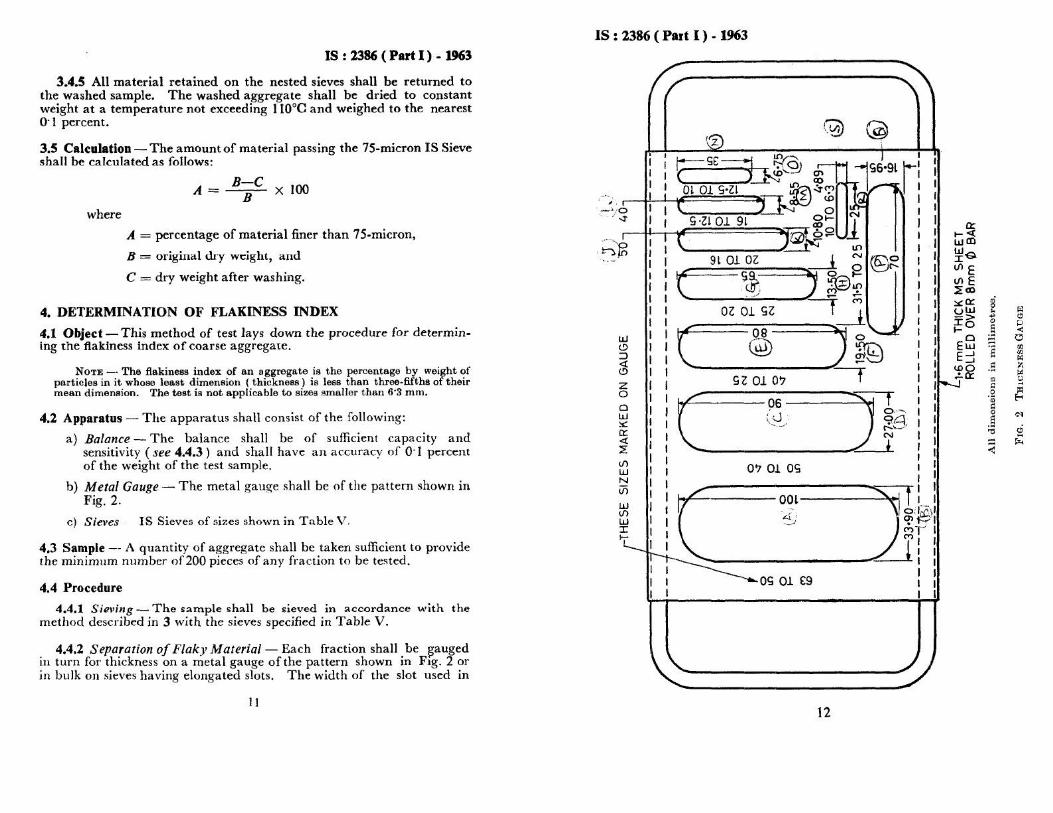
2) Metal Gauge – The metal gauge shall be of the pattern as shown in Fig
3) Sieves – The sieves of sizes as shown in Table
PRINCIPLE The flakiness index of an aggregate is the percentage by weight of particles in it
whose leastdimension (thickness) is less than three-fifths of their mean dimension. The test is
notapplicable to sizes smaller than 6.3mm.
PROCEDURE
1. A quantity of aggregate shall be taken sufficient to provide the minimum number of200
pieces of any fraction to be tested.
2. The sample shall be sieved with sieves specified in Table
3. Then each fraction shall be gauged in turn for thickness on a metal gauge of the pattern
shown in Fig 4 or in bulk on sieves having elongated slots. The width of the slot used in
the gauge or sieve shall be of the dimensions specified in column 3 of Table for the
appropriate size of material.
4. The total amount of aggregate passing the gauge shall be weighed to an accuracy of at
least 0.1 percent of the weight of the test sample.

Concrete & Highway Materials Laboratory 10CVL-78 2017-18
Dept of Civil Engg, CIT Gubbi Page 61

Concrete & Highway Materials Laboratory 10CVL-78 2017-18
Dept of Civil Engg, CIT Gubbi Page 62
SIZE OF AGGREGATE
(mm) THICKNESS LENGTH
Passing
through IS
sieve
Retained on
IS sieve THICKNESS
GAUGE(mm)
LENGTH
GAUGE(mm)
63 50 33.90 -
50 40 27.00 81.0
40 31.5 19.50 58.5
31.5 25 16.95 -
25 20 13.50 40.5
20 16 10.80 32.4
16 12.5 8.55 25.6
12.5 10 6.75 20.2
10 6.3 4.89 14.7
Dimensions of Thickness and Length gauge
*This dimension is equal to 0.6 times the mean sieve size.
This dimension is equal to 1.8 times the mean sieve size. RESULT=

Concrete & Highway Materials Laboratory 10CVL-78 2017-18
Dept of Civil Engg, CIT Gubbi Page 63
Length Gauge
CALUCULATIONS Elongation index=
Where,xis the weight of materials retained on specified gauges and W is the total weights of
aggregate passing and retained on the specified sieves.

Concrete & Highway Materials Laboratory 10CVL-78 2017-18
Dept of Civil Engg, CIT Gubbi Page 64
B. ELONGATION INDEX
AIM: This method of test lays down the procedure for determining the elongation index of the
coarse aggregate.
APPARATUS
a) The apparatus shall consist of the following:
b) A balance – The balance shall be of sufficient capacity and sensitivity and shall have an
accuracy of 0.1 percent of the weight of the test sample
c) Metal Gauge – The metal gauge shall be of the pattern as shown in Fig
d) Sieves – The sieves of sizes as shown in Table
THEORY The elongation index of an aggregate is the percentage by weight of particles in it whose
greatest dimension (thickness) is greater than one and four-fifths of their mean dimension. The test is not
applicable to sizes smaller than 6.3mm.
PROCEDURE
1. A quantity of aggregate shall be taken sufficient to provide the minimum number of 200
pieces of any fraction to be tested.
2. The sample shall be sieved with sieves specified in Table
3. Each fraction shall be gauged in turn for length on a metal gauge of the pattern shown in
Fig. The gauge length used shall be of the dimensions specified in column 4 of Table for
the appropriate size of material.
4. The total amount of aggregate retained by the length gauge shall be weighed to an
accuracy of at least 0.1 percent of the weight of the test sample
RESULT

Concrete & Highway Materials Laboratory 10CVL-78 2017-18
Dept of Civil Engg, CIT Gubbi Page 65
Penetrometer
OBSERVATIONS & CALCULATIONS:
SL. No. Particulars Test 1 Test 2 Test 3
1.
Penetrometer Dial reading
a) Initial
b) Final
2. Penetration Value
Mean Penetration Value =

Concrete & Highway Materials Laboratory 10CVL-78 2017-18
Dept of Civil Engg, CIT Gubbi Page 66
Exp No: Date:
PENETRATION TEST
AIM: To determine the consistency of bituminous material
APPARATUS:
a) Container A flat bottomed cylindrical metallic dish 55 mm in diameter and 35 mm in
depth is required. If the penetration is of the order of 225 or more deeper dish of 70 mm
diameter and 45 mm depth is required.
b) Needle: A straight, highly polished, cylindrical hard steel rod, as per standard dimensions
c) Water bath-A water bath maintained at 25±0.10Ccontaining about 10ltrs. Of water. The
sample being immersed to a depth not less of than 100mm from the top & supported on a
performed shell not less than from the bottom of the bath.
d) Transfer dish or tray: It should provide support to the container and should not rockthe
container. It should be of such capacity as to completely immerse the containerduring the
test.
e) Penetration apparatus: It should be such that it will allow the needle to penetrate
without much friction and is accurately calibrated to give results in one tenth of a
millimeter
f) Thermometer: Range 0- 440 C and readable up to 0.20C
g) Time measuring device: With an accuracy ± 0.1 sec
THEORY
Penetration value is a measurement of hardness or consistency of bituminous material. It is the
vertical distance traversed or penetrated by the point of a standard needle in to the bituminous
material under specific conditions of load, time, and temperature. This distance is measured in
one tenth of a millimeter. This test is used for evaluating consistency of bitumen. It is not
regarded as suitable for use in connection with the testing of road tar because of the high surface
tension exhibited by these materials and the fact that they contain relatively large amount of free
carbon.

Concrete & Highway Materials Laboratory 10CVL-78 2017-18
Dept of Civil Engg, CIT Gubbi Page 67

Concrete & Highway Materials Laboratory 10CVL-78 2017-18
Dept of Civil Engg, CIT Gubbi Page 68
PROCEDURE:
1. Preparation of test specimen- Soften the material to a pouring consistency at a
temperature not more than 600C for tars and 90
0C for bitumen’s above the approximate
softening point and stir it thoroughly until it is homogeneous and is free from air bubbles
and water. Pour the melt into the container to a depth at least 10mm in excess of the
excepted penetration. Protect the sample from dust and allow it to cool in an atmosphere
at a temp. Between 150C to 30
0C for an hour. Then place it along with the transfer dish in
the water bath at 250C ±0.1
0C & aloe it remain for one to one and half hour. The test is
carried out at 250C ±0.1
0C unless otherwise stated.
2. Fill the transfer dish water from the water bath to depth sufficient to cover the container
completely. Place the sample in it and put it upon the sand of the penetration apparatus.
3. Clean the needle with benzene, dry it load with the weight, the total moving load required
is 100±0.25gms. Including the weight of the needle, carrier, and superimposed weights.
4. Adjust the needle with to make contact with surface if the sample. This may be done by
placing the needle point in contact with its image reflected by the surface of the
bituminous material.
5. Make the pointer of the dial to read zero or note the initial dial reading.
6. Release the needle for exactly 5 sec.
7. Adjust the penetration machine to measure the distance penetrated.
8. Make at least 3 readings at points on the surface of the sample not less than 10mm apart
and not less than 10mm from the side of the dish, after each test return the sample and
transfer dish to the water bath & wash the needle. Clean with benzene& dry it in case of
material of penetration greater then 225,3 determinations on each of the 2 identical test
specimens using a separate needle for each determine should be made, leaving the needle
in the sample on completion of each determinations to avoid disturbance of the specimen.
RESULT

Concrete & Highway Materials Laboratory 10CVL-78 2017-18
Dept of Civil Engg, CIT Gubbi Page 69

Concrete & Highway Materials Laboratory 10CVL-78 2017-18
Dept of Civil Engg, CIT Gubbi Page 70
STANDARDS
The Indian Standards Institution has classified paving bitumen available in this country into
the following six categories depending on the penetration values. Grades designated ‘A’
(such as A 35) are from Assam Petroleum and those designated ‘S’ (such as S 35) are from
other sources.
Bitumen
Grade A25
A 35 &
S 35
A 45 &
S 45
A 65 &
S 65
A 90 &
S 90
A 200 &
S 200
Penetration
Value 20 to 30 30 to 40 40 to 50 60 to 70 80 to 100 175 to 225

Concrete & Highway Materials Laboratory 10CVL-78 2017-18
Dept of Civil Engg, CIT Gubbi Page 71
Briquette Mould
Ductility Testing Machine
OBSERVATIONS AND CALCULATION:
Sl.no Particulars
Briquette mould no.
1 2 3
1 Initial reading = a =
2 Final reading = b =
3 Ductility in cms = b =

Concrete & Highway Materials Laboratory 10CVL-78 2017-18
Dept of Civil Engg, CIT Gubbi Page 72
Exp No: Date:
DUCTILITY TEST
AIM: To measure the ductility of a given sample of bitumen. APPARATUS
a) Briquette mould: It is made up of brass with the shape as shown in fig. The ends b &b are
known as clips and the parts a & a as sides of the mould, the dimensions of the mould shall be
such that when properly assembled it will form a briquette specimen having the following
dimensions.
a. Total length 75.0±0.5mm
b. Distance between clips 30.0±0.3mm
c. Width at mouth of clip 20.0±0.2mm
d. Width at min. cross section
e. (Half way between clips) 10.0±0.1mm
f. Thickness through h out 10.0±0.1mm
b) Water bath: The water bath must have a thermostat maintained with in ±0.10C of the specified
test temperature it should contain 10ltrs. Of water. The specimen is to be immersed up to a depth
of not less than 100mm being supported on a perforated shelf of about 50mm from the bottom of
the bath.
c) Testing machine: For pulling a briquette of bituminous material apart, any apparatus may be
used which is so constructed that the specimen will be continuously immersed in water while the
two clips of pulled apart horizontally at a uniform specific a speed. It also must have suitable
arrangements for stirring water to attain uniform temperature.
THEORY
The ductility test gives a measure of adhesive property of bitumen and its ability to stretch. In a
flexible pavement design, it is necessary that binder should form a thin ductile film around the
aggregates so that the physical interlocking of the aggregates is improved. Binder material
having insufficient ductility gets cracked when subjected to repeat traffic loads and it provides
pervious pavement surface. Ductility of a bituminous material is measured by the distance in
centimeters to which it will elongate before braking when two ends of standard briquette

Concrete & Highway Materials Laboratory 10CVL-78 2017-18
Dept of Civil Engg, CIT Gubbi Page 73

Concrete & Highway Materials Laboratory 10CVL-78 2017-18
Dept of Civil Engg, CIT Gubbi Page 74
specimen of the material are pulled apart at a specified speed and at a specified temperature.
PROCEDURE
Preparation of test specimen: The test specimen is prepared by melting the bituminous material
by a temperature 750C to 100
0C approximate. Above the softening point until it becomes
thoroughly fluid. The mould is assembled on a brass plate & its interiors as well as brass plate
should be coated with on equal mixture of glycerine&dextine to prevent sticking the fluid
materials is then poured in a thin stream, back& forth from end to end mould until it is more than
full. It is closed to room temp. For 30-40min. and then placed in the water bath for 30mins. After
which the excess is cutoff by means of hot spatula so that the mould shall be just full & level.
a) Remove the side pieces and brass plate
b) Keep the briquette mould in the testing machine and hook the clips carefully with out
causing any initial strain.
c) Adjust the pointer to read zero or initial reading of the pointer to be noted.
d) Start the machine & pull two clips horizontally at a speed of50mm/min.
e) Note the distance at which the bitumen thread of specimen breaks.
PRECAUTIONS:
1. The plate assembly upon which the mould is placed shall be perfectly flat & level so that the
bottom surface of the mould touches it throughout.
2. In filling the mould, care should be taken not to disarrange the parts & thus distort the briquette &
to see that no air pockets shall be with in the molded sample.
3. If the bituminous material comes in contact with water surface or rests on the bottom of the water
bath the test should not be considered as normal. In that case, the specific gravity of water is
adjusted by adding either methyl alcohol or sodium chloride so that the bituminous material
doesn’t comes to the surface or touch the bottom at any time during the test.
RESULT

Concrete & Highway Materials Laboratory 10CVL-78 2017-18
Dept of Civil Engg, CIT Gubbi Page 75

Concrete & Highway Materials Laboratory 10CVL-78 2017-18
Dept of Civil Engg, CIT Gubbi Page 76
STANDARD RESULTS:
The suitability of bitumen is judged, depending upon its type and proposed use. Bitumen
with low ductility value may get cracked especially in cold water. ISI has specified following
values of min. ductility for various grades of bitumen as follows.
Source of paving bitumen and penetration grade Minimum ductility value in cms.
Assam petroleum A 25
A 35
A 45
A65, A90 & A200
5
10
12
15
Bitumen from sources other than Assam petroleum
S35
S45,S65,S90
50
75
COMMENTS

Concrete & Highway Materials Laboratory 10CVL-78 2017-18
Dept of Civil Engg, CIT Gubbi Page 77
Assembly of Apparatus For Determination of Softening
Point (Ring & Ball)
OBSERVATION & CALCULATIONS:
Liquid Used In the Bath
Temperature when the
ball touches bottom (0C)
Ball 1 Ball 2
Average

Concrete & Highway Materials Laboratory 10CVL-78 2017-18
Dept of Civil Engg, CIT Gubbi Page 78
Exp No: Date:
SOFTENING POINT TEST
AIM: To determine the softening point of given bituminous material
APPARATUS Ring and Ball apparatus, Water bath with stirrer, Thermometer, Glycerin,etc.
Steel balls each of 9.5mm and weight of 2.5±0.08gm.
THEORY: The softening point of bitumen or tar is the temperature at which the substance
attains a particular degree of softening. As per IS:334-1982, it is the temperature (in o C) at
which a standard ball passes through a sample of bitumen in a mould and falls through a height
of 2.5 cm, when heated under water or glycerin at specified conditions of test. The binder should
have sufficient fluidity before its applications in road uses. The determination of softening point
helps to know the temperature up to which a bituminous binder should be heated for various road
use applications. Softening point is determined by ring and ball apparatus.
PROCEDURE
Preparation of test sample:Heat the material to a temperature between 750c to 100
0c above its
softening point. Stir until it is completely fluid & free from air bubbles and water if necessary filter it
throws IS sieve 30. Place the rings, previously heated to a temperature approximating to that of the
molten material, on a metal plate which has been smeared with a mixture in air, level the material in the
ring by removing the excess with a warmed sharp knife.
1. Assemble the apparatus with rings, thermometer& ball guides in position.
2. Fill the bath distilled water to a height of 50mm above the upper surface o the rings.
3. Apply each to the bath & stir the liquid so the temperature rises at a uniform rate of
a. 5+0. 50c/minute.
4. As the temperature increases the bituminous material softness & the balls sinks through
the ring, carrying a portion of the material with it.
5. Note down the temperature when any of the steel with bituminous coating touches the
bottom plate.

Concrete & Highway Materials Laboratory 10CVL-78 2017-18
Dept of Civil Engg, CIT Gubbi Page 79

Concrete & Highway Materials Laboratory 10CVL-78 2017-18
Dept of Civil Engg, CIT Gubbi Page 80
6. Record the temperature when the second ball also touches the bottom plate.
7. The average of the two readings to the nearest 0.50c is reported as the softening point.
Note:Use Glycerin in place of water if the softening point is excepted to be above 800c & the
starting temperature of the test is 350c
PRECAUTIONS:
1. Distilled water should be used as the heating medium.
2. During the conduct of test the apparatus should not be subjected to vibrations.
3. The bulb of the thermometer should be at about the same level as the rings.
STANDARD RESULTS: Softening point indicates the temperature at which binders
possess the viscosity. Bituminous materials do not have a definite melting point; rather the
change of state form solid to liquid is gradually & over a wide range of temperature.
Softening point as particular significance for materials that are to be used as joint & crack
fillers. Higher softening point ensures that they will not flow during service. In general, the
higher the softening point the lesser the susceptibility. Bitumen with higher softening point
may be prepared in warmer places. The result obtained shall not differ from the mean by
more than the following.
Softening point(0c) Repeatability (
0c) Reproducibility(
0c)
40-60
61-80
81-100
101-120
121-140
1.0
1.5
2.0
2.5
3.0
5.5
5.5
5.5
5.5
5.5
RESULT

Concrete & Highway Materials Laboratory 10CVL-78 2017-18
Dept of Civil Engg, CIT Gubbi Page 81

Concrete & Highway Materials Laboratory 10CVL-78 2017-18
Dept of Civil Engg, CIT Gubbi Page 82
The ranges of softening point specified by the Indian Standards Institution for various grades of
bitumen are given below.
Bitumen Grades Softening
point, °C
*A25&A35
*S35
A45,S45&A65
S65
A90&590
A 200 & S 200
55 to 70
50 to 65
45 to 60
40 to 55
35 to 50
30 to 45
* A denotes bitumen from Assam Petroleum, and ‘S’ denotes bitumen from sources other than
from Assam Petroleum. Also see Table under ‘Application of penetration test.
COMMENTS

Concrete & Highway Materials Laboratory 10CVL-78 2017-18
Dept of Civil Engg, CIT Gubbi Page 83

Concrete & Highway Materials Laboratory 10CVL-78 2017-18
Dept of Civil Engg, CIT Gubbi Page 84
Exp No: Date:
FLASH & FIRE POINT TEST FOR BITUMINOUS SAMPLE
AIM: To determine the flash and fire point for the given bituminous sample
APPARATUS:
a. Open Cup Tester is same as standard Pensky-Marten tester with the modification that
cover of the cup is replaced by a clip which encircles the upper rim of the cup and carries
a test flame
b. Thermometer
c. A stove / heating device with provision to adjust the rate of heating
THEORY: The flash point of a material is the lowest temperature at which the application of test flame
causes the vapors from the material momentarily catch fire in the form of a flash under specified
conditions of test.
The fire point is the lowest temperature at which the application of test flame causes the material to ignite
and burn at least for 5s under specified conditions of test.
PROCEDURE
1. All the parts of the open cup tester and the accessories are cleaned and dried.
2. The cup is filled with the sample of bituminous binder up to the level of the filling mark.
3. The clip supporting the thermometer and test flame is placed in position on the cup.
4. The thermometer is inserted and the open cup tester is set on the stove.
5. The test flame is lighted and adjusted to size 4 mm bead and it is fixed in the vertical axis
of the cup, level with the upper edge of the cup.
6. The bitumen sample in the tester is heated and the rate of heating is adjusted such that the
temperature of the test specimen increases at the rate of 5°C to 6°C per minute.
7. A burning match stick is placed at the binder surface from time to time and the
appearance of flash, if any, is observed.
8. When the flash occurs the first time, the temperature at that instance is recorded as the
flash point.

Concrete & Highway Materials Laboratory 10CVL-78 2017-18
Dept of Civil Engg, CIT Gubbi Page 85

Concrete & Highway Materials Laboratory 10CVL-78 2017-18
Dept of Civil Engg, CIT Gubbi Page 86
REPORTING OF RESULTS
The temperature of the binder when flash first appears at any point on the surface of the
material is noted and recorded as the flash point under open cup flash point test.
The heating is continued at the same rate until the binder itself gets ignited and continues to burn
for five seconds. When it occurs, the temperature of the material is noted and is recorded as the
fire point.
RESULT
1. Flash point of the given bituminous material ………..
2. Fire point the given bituminous material ………..

Concrete & Highway Materials Laboratory 10CVL-78 2017-18
Dept of Civil Engg, CIT Gubbi Page 87
OBSERVATIONS & CALCULATIONS:
Sl.no. Particulars Test 1 Test2
1. Test temperature
2. Time taken to follow50cc of the binder
3. Viscosity in Sec.

Concrete & Highway Materials Laboratory 10CVL-78 2017-18
Dept of Civil Engg, CIT Gubbi Page 88
Exp No: Date:
VISCOSITY TEST
AIM:To determine the viscosity of given bituminous material.
APPARATUS: A orifice viscometer (one of 4.0mm diameter used to test cut back grades 0 and
1 and 10mm orifice to test all other grades), water bath, stirrer and thermometer.
THEORY: Viscosity of a fluid is the property by virtue of which it offers resistance to flow.
Higher the viscosity, the slower will be the movement of the liquid. The viscosity affects the
ability of the binder to spread, move into, & fill up the voids between aggregates. It also place on
important. Role in coating of aggregates. Highly viscous binder may not fill up the voids
completely there by resulting in poor density of the mix. At lower viscosity the binder does not
hold the aggregates together but just acts as lubricant the viscosity of bituminous binders falls
very rapidly as the temperature rises since binders exhibit viscosity over a wider range, it is
necessary to use different methods for the determination of viscosity for binder in the liquid
state (Road tars & cutback bituminous),the viscosity is determined as the time in sec. by 50cc of
the material to flow from a cup through specified orifice under standard conditions to test & at
specified temperature. Equipment like sliding plate micro viscometer, & brook field viscometer
are however in used for defining the viscous characteristics of the bitumen of all grades
irrespective of testing temperature.
PROCEDURE:
1. Adjust the tar viscometer so that the top of the tar cup is leveled select the test temp.
From table1. Heat the water in the water bath to the temp. Specified for the test &
maintain it with in ±0.10c of the specified temp. Throughout the duration of test.
Rotate the stirrer gently at frequent intervals or continuously.
2. Clean the Tar cup, orifice of the viscometer with a suitable solvent and dry
thoroughly.
3. Warm and stir the material under examination to 200c above the temp. Specified for
test & cool while continuing the stirring.

Concrete & Highway Materials Laboratory 10CVL-78 2017-18
Dept of Civil Engg, CIT Gubbi Page 89

Concrete & Highway Materials Laboratory 10CVL-78 2017-18
Dept of Civil Engg, CIT Gubbi Page 90
4. When the temp. Falls slightly above the specified temp, pour the tar in to the cup
until the leveling peg ion the valve rods is just immersed when the latter is vertical.
5. Pour in to the graduated receiver 20ml; of mineral oil or one %by weight, solution of
soft soap & place it under with orifice of the cup.
6. Place the other thermometer in the tar & stir until the temp. is with in ±0.10c of the
specified temp. When this temp. Has been reached .suspended the thermometer
coaxially with the cup & with its bulb approximately at the geometric center of the
tar.
7. Hallow the assembled apparatus to stand for 5 min. during which period the
thermometer reading should remain within 0.050c of the specified temp. Remove the
temp. & quickly remove any excess tar so that the final level is on the central line on
the leveling peg when the valve is in vertical position.
8. Lift the valve & suspend it on valve support
9. Start the stop watch when the reading in the cylinder is 25ml & stop when it is 75ml,
note the time in sec.
10. Report the viscosity as the time taken in sec. by 50 ml. of tar to flow out at the temp.
Specified for the test.
PRECAUTIONS:
a. The tar cup should be cleaned thoroughly with non- corroding solvents such as light
tar oils free from phenols.
b. The orifice seize should be tested at frequent intervals with a gauge having a
appropriate diameters.
REAULT

Concrete & Highway Materials Laboratory 10CVL-78 2017-18
Dept of Civil Engg, CIT Gubbi Page 91
MARSHALLA STABILITY APPARATUS

Concrete & Highway Materials Laboratory 10CVL-78 2017-18
Dept of Civil Engg, CIT Gubbi Page 92
Exp No: Date:
BITUMINOUS MIS DESIGN BY MARSHALL METHOD
AIM:To determine optimum binder content of given bituminous mix by Marshall Method ofmix
design.
APPARATUS:Mould assembly, sample extractor, compaction pedestal and hammer, breaking
head,loading machine flow meter, thermometers water bath and oven
THEORY
In this method, the resistance to plastic deformations of cylindrical specimen of bituminous
mixture is measured when the same is added at the periphery at 5 cm per minute. This test
procedure is used in designing and evaluating bituminous paving mixes. The test procedure is
extensively used in routine test programs for the paving jobs. There are two major features of the
Marshall method of designing mixes namely, (i) density-voids analysis (ii) stability-now tests.
The Marshall stability of the mix is defined as a maximum load carried by a compacted specimen
at a standard test temperature at 60°C. The flow value is the deformation the Marshall test
specimen undergoes during the loading upto the maximum load, in 0.25 mm units. In this test an
attempt is made to obtain optimum binder content for the type of aggregate mix and traffic
intensity
PROCEDURE:
1. The coarse aggregates, fine aggregates and mineral filler material should be proportioned
and mixed in such a way that final mix after blending has the graduation within the
specified range.
2. Approximately 1200 grams of aggregates and filler are taken and heated to a temperature
of 175oC to 195O C.
The compaction mould assembly and rammer are cleaned and kept pre- heated to a
temperature of 100oC to 145oC. The bitumen is heated to temperature of 121oC to 138oC
and the required quantity of first trial percentage o f bitumen is added to the heated
aggregate and thoroughly mixed using a mechanical mixer or by hand mixing with
trowel.

Concrete & Highway Materials Laboratory 10CVL-78 2017-18
Dept of Civil Engg, CIT Gubbi Page 93

Concrete & Highway Materials Laboratory 10CVL-78 2017-18
Dept of Civil Engg, CIT Gubbi Page 94
3. Then the mix is heated and a temperature of 150o to 160oC is maintained and then the
mix is transferred into the pre-heated mould and compacted by giving seventy five blows
on each side.
4. The specific gravity values of different aggregates, filler and bitumen used are
determined first. The theoretical specific gravity of the mix is determined.
5. Soon after the compacted bituminous mix specimens have cooled to room temperature,
the weight, average thickness and diameter of the specimen are noted. The specimens are
weighted in air and then in water.
6. The bulk density value of the specimen if calculated from weight and volume
7. Then the specimen to be tested is kept immersed under water in a thermostatically
controlled water bath maintained at 600 ±1
0C for 30 to 40 minutes.
8. The specimens are taken out one, placed in the marshal test and the marshal stability
value and flow are noted.
9. The corrected Marshall Stability value of each specimen is determined by applying the
appropriate correction factor, if the average height of the specimen is not exactly
63.5mm.
10. Five graphs are plotted with values of bitumen content against the values of density,
Marshall Stability, voids in total mix, flow value, voids filled by bitumen.
11. Let the bitumen contents corresponding to maximum density be B1, corresponding
tomaximum stability be B2 and that corresponding to the specified voids content (at
4.0%)be B3. Then the optimum bitumen content for mix design is given by: Bo =
(B1+B2+B3)/3
RESULT: The optimum binder content of the given mix is…….

Concrete & Highway Materials Laboratory 10CVL-78 2017-18
Dept of Civil Engg, CIT Gubbi Page 95
CALCULATION
The specific gravity of the bituminous material is calculated as follows:
(i) Pyknometer method
Specific gravity= )()(
)(
Cat27 wateof volumeequal ofWeight
material bituminous ofweight
cdab
ac
−−−
−=
°
a = weight of specific gravity bottle
b = weight of the specific gravity bottle filled with distilled water
c = weight of the specific gravity bottle about half filled with bituminous material.
d = weight of the specific gravity bottle about half filled with the material and the rest with
distilled water.

Concrete & Highway Materials Laboratory 10CVL-78 2017-18
Dept of Civil Engg, CIT Gubbi Page 96
Exp No: Date:
SPECIFIC GRAVITY TEST
AIM: To determine the specific gravity of given sample of water.
APPARATUS:There are two methods (i) Pyknometer method (ii) Balance method. For
pyknometer method, the apparatus are specific gravity bottle of 50 ml capacity, ordinary
capillary type with 6 mm diameter neck or wide mouthed capillary type bottle with 25 nm
diameter neck can be used. For balance method an analytical balance equipped with a pan
straddle is used.
PROCEDURE:
The specific gravity bottle is cleaned, dried arid weighed along with the stopper. It is filled with
fresh distilled water, stopper placed and the same is kept in water container for at least half an
hour at temperature 27°c ± 0.1°C. The bottle is then removed and cleaned from outside. The
specific gravity bottle containing, distilled water is now weighed.
The bituminous material is heated to a pouring temperature and is poured in the above empty
bottle taking all the precautions that it is dean and dry before filling sample materials. The
material is filled upto the half taking care to prevent entry of air bubbles. To permit an escape of
air bubbles, the sample bottle is allowed to stand for half an hour at suitable temperature cooled
to 27°C and then weighed. The remaining space in the specific gravity bottle is filled with
distilled water at 27°C, stopper placed and is, placed in water container at 27°C. The bottle
containing bituminous material and containing water is removed, cleaned from outside and is
again weighed.
STANDARDS
The Indian Standard institution specifies that the minimum specific gravity values of paving
bitumen at 27°C shall be 0.99 for grades A 25, A 35, A 45, A 65, S 35, S 45, and S 65, 0.98 for
A 0 and S 90 and 0.97 for A 200 and S 200. (For classification of bitumen, see Table under
Experiment No. 17, ‘Applications of penetration test).
RESULT

Concrete & Highway Materials Laboratory 10CVL-78 2017-18
Dept of Civil Engg, CIT Gubbi Page 97
Sl
no Data (Calibration of Unit Weight of Sand) Trial-1
1 Volume of the calibrating container, V (cm3)
2 Weight of SPC + sand, W1 (g)
3
Weight of sand required to fill the conical portion on a flat
surface, W2 (g)
4 Weight of SPC + sand (after filling calibrating can), W3 (g)
5
Weight of sand required to fill the calibrating container,
Wc = (W1-W2 –W3) (g)
6
Unit weight of sand,
γsand = (Wc)/V (g/cm3)
Sl.
No Data (Determination of Density of Soil) Trial-1
1 Weight of the excavated from the pit (W) (g)
2 Weight of sand + SPC, before pouring, W1 (g)
3 Weight of SPC after filling the hole & conical portion, W4 (g)
4
Weight of sand in the pit
Wp = (W1-W4-W2) (g)
5
Volume of sand required to fill the pit
Vp=Wp/γsand (cm3)
6
Wet unit weight of the soil
γwet=W/Vp (g/cm3)
7
Dry unit weight of the soil γdry=γwet/(1+m) (g/cm3) (where ‘m’ is
the moisture content of soil)

Concrete & Highway Materials Laboratory 10CVL-78 2017-18
Dept of Civil Engg, CIT Gubbi Page 98
Exp No: Date:
DENSITY OF SOIL BY SAND REPLACEMENT METHOD
AIM: To determine the field density of soil at a given location by sand replacement method
APPRATUS:
1. Sand pouring cylinder
2. Calibrating can
3. Metal tray with a central hole
4. Dry sand (passing through 600 micron sieve)
5. Balance
6. Moisture content bins
7. Glass plate
8. Metal tray
9. Scraper tool
THEORYDetermination of field density of cohesion less soil is not possible by core cutter
method, because it is not possible to obtain a core sample. In such situation, the sand
replacement method is employed to determine the unit weight. In sand replacement method, a
small cylindrical pit is excavated and the weight of the soil excavated from the pit is measured.
Sand whose density is known is filled into the pit. By measuring the weight of sand required to
fill the pit and knowing its density the volume of pit is calculated. Knowing the weight of soil
excavated from the pit and the volume of pit, the density of soil is calculated. Therefore, in this
experiment there are two stages, namely
1. Calibration of sand density
2. Measurement of soil density
PROCEDURE
STAGE-1 (CALIBRATION OF SAND DENSITY)
1. Measure the internal dimensions (diameter, d and height, h) of the calibrating can and compute its
internal volume, Vc = πd2h/4.
2. Fill the sand pouring cylinder (SPC) with sand with 1 cm top clearance (to avoid any spillover
during operation) and find its weight (W1)

Concrete & Highway Materials Laboratory 10CVL-78 2017-18
Dept of Civil Engg, CIT Gubbi Page 99

Concrete & Highway Materials Laboratory 10CVL-78 2017-18
Dept of Civil Engg, CIT Gubbi Page 100
3. Place the SPC on a glass plate, open the slit above the cone by operating the valve and allow the
sand to run down. The sand will freely run down till it fills the conical portion. When there is no
further downward movement of sand in the SPC, close the slit. Measure the weight of the
sand required to fill the cone. Let it be W2.
4. Place back this W2 amount of sand into the SPC, so that its weight becomes equal to W1 (As
mentioned in point-2). Place the SPC concentrically on top of the calibrating can. Open the slit to
allow the sand to run down until the sand flow stops by itself. This operation will fill the calibrating
can and the conical portion of the SPC. Now close the slit and find the weight of the SPC with the
remaining sand (W3)
STAGE-2 (MEASUREMENT OF SOIL DENSITY)
1. Clean and level the ground surface where the field density is to be determined
2. Place the tray with a central hole over the portion of the soil to be tested.
3. Excavate a pit into the ground, through the hole in the plate, approximately 12 cm deep (same as
the height of the calibrating can). The hole in the tray will guide the diameter of the pit to be made in
the ground.
4. Collect the excavated soil into the tray and weigh the soil (W)
5. Determine the moisture content of the excavated soil.
6. Place the SPC, with sand having the latest weight of W1, over the pit so that the base of the
cylinder covers the pit concentrically.
7. Open the slit of the SPC and allow the sand to run into the pit freely, till there is no downward
movement of sand level in the SPC and then close the slit.
8. Find the weight of the SPC with the remaining sand (W4)
PRECAUTIONS
� If for any reason it is necessary to excavate the pit to a depth other than 12 cm, the
standard calibrating can should be replaced by one with an internal height same as the depth
of pit to be made in the ground.
� Care should be taken in excavating the pit, so that it is not enlarged by levering, as this
will result in lower density being recorded.
� No loose material should be left in the pit.
� There should be no vibrations during this test.
� It should not be forgotten to remove the tray, before placing the SPC over the pit.

Concrete & Highway Materials Laboratory 10CVL-78 2017-18
Dept of Civil Engg, CIT Gubbi Page 101
OBSERVATION AND RECORDING
For Dynamic Compaction
• Optimum water content (%)
• Weight of mould + compacted specimen g
• Weight of empty mould g Weight of compacted specimen g
• Volume of specimen
• Bulk density g/cc
• Dry density g/cc
For static compaction
• Dry density g/cc
• Moulding water content %
• Wet weight of the compacted soil,(W)g
• Period of soaking 96 hrs. (4days).
For penetration Test
• Calibration factor of the proving ring 1 Div. = 1.176 kg
• Surcharge weight used (kg) 2.0 kg per 6 cm construction
• Water content after penetration test %
• Least count of penetration dial 1 Div. = 0.01 mm

Concrete & Highway Materials Laboratory 10CVL-78 2017-18
Dept of Civil Engg, CIT Gubbi Page 102
Exp No: Date:
CALIFORNIA BEARING RATIO TEST
AIM: To determine the California bearing ratio by conducting a load penetration test in the
laboratory.
APPARATUS:
1.Cylindricalmould with inside dia 150 mm and height 175 mm, provided with a
detachable extension collar 50 mm height and a detachable perforated base plate 10 mm
thick.
2.Spacer disc 148 mm in dia and 47.7 mm in height along with handle.
3Metal rammers. Weight 2.6 kg with a drop of 310 mm (or) weight 4.89 kg a drop 450
mm.
4.Weights. One annular metal weight and several slotted weights weighing 2.5 kg each,
147 mm in dia, with a central hole 53 mm in diameter.
5.Loading machine. With a capacity of atleast 5000 kg and equipped with a movable
head or base that travels at an uniform rate of 1.25 mm/min. Complete with load
indicating device.
6.Metal penetration piston 50 mm dia and minimum of 100 mm in length.
7.Two dial gauges reading to 0.01 mm.
8.Sieves. 4.75 mm and 20 mm I.S. Sieves.
9.Miscellaneous apparatus, such as a mixing bowl, straight edge, scales soaking tank or pan,
drying oven, filter paper and containers.
DEFINITION OF C.B.R. It is the ratio of force per unit area required to penetrate a soil mass
with standard circular piston at the rate of 1.25 mm/min. to that required for the corresponding
penetration of a standard material.
C.B.R. = Test load/Standard load * 100

Concrete & Highway Materials Laboratory 10CVL-78 2017-18
Dept of Civil Engg, CIT Gubbi Page 103

Concrete & Highway Materials Laboratory 10CVL-78 2017-18
Dept of Civil Engg, CIT Gubbi Page 104
The following table gives the standard loads adopted for different penetrations for the standard
material with a C.B.R. value of 100%
Penetration of plunger (mm) Standard load (kg)
2.5
5.0
7.5
10.0
12.5
1370
2055
2630
3180
3600
The test may be performed on undisturbed specimens and on remoulded specimens which may
be compacted either statically or dynamically.
PREPARATION OF TEST SPECIMEN Undisturbed specimen Attach the cutting edge to the
mould and push it gently into the ground. Remove the soil from the outside of the mould which
is pushed in . When the mould is full of soil, remove it from weighing the soil with the mould or
by any field method near the spot.
Determine the density
Remoulded specimenPrepare the remoulded specimen at Proctors maximum dry density or any
other density at which C.B.R> is required. Maintain the specimen at optimum moisture content
or the field moisture as required. The material used should pass 20 mm I.S. sieve but it should be
retained on 4.75 mm I.S. sieve. Prepare the specimen either by dynamic compaction or by static
compaction.
Dynamic Compaction Take about 4.5 to 5.5 kg of soil and mix thoroughly with the required
water.
Fix the extension collar and the base plate to the mould. Insert the spacer disc over the base.
Place the filter paper on the top of the spacer disc.
Compact the mix soil in the mould using either light compaction or heavy compaction. For light
compaction, compact the soil in 3 equal layers, each layer being given 55 blows by the 2.6 kg
rammer. For heavy compaction compact the soil in 5 layers, 56 blows to each layer by the 4.89
kg rammer.

Concrete & Highway Materials Laboratory 10CVL-78 2017-18
Dept of Civil Engg, CIT Gubbi Page 105

Concrete & Highway Materials Laboratory 10CVL-78 2017-18
Dept of Civil Engg, CIT Gubbi Page 106
Remove the collar and trim off soil.
Turn the mould upside down and remove the base plate and the displacer disc.
Weigh the mould with compacted soil and determine the bulk density and dry density.
Put filter paper on the top of the compacted soil (collar side) and clamp the perforated base plate
on to it.
Static compaction
Calculate the weight of the wet soil at the required water content to give the desired density
when occupying the standard specimen volume in the mould from the expression.
W =desired dry density * (1+w) V
Where W = Weight of the wet soil
w = desired water content
V = volume of the specimen in the mould = 2250 cm3 (as per the mould available in laboratory)
Take the weight W (calculated as above) of the mix soil and place it in the mould.
Place a filter paper and the displacer disc on the top of soil.
Keep the mould assembly in static loading frame and compact by pressing the displacer disc till
the level of disc reaches the top of the mould.
Keep the load for some time and then release the load.
Remove the displacer disc. The test may be conducted for both soaked as well as unsoaked
conditions.
If the sample is to be soaked, in both cases of compaction, put a filter paper on the top of the soil
and place the adjustable stem and perforated plate on the top of filter paper.
Put annular weights to produce a surcharge equal to weight of base material and pavement
expected in actual construction. Each 2.5 kg weight is equivalent to 7 cm construction. A
minimum of two weights should be put.
Immerse the mould assembly and weights in a tank of water and soak it for 96 hours. Remove
the mould from tank. Note the consolidation of the specimen.
Procedure for Penetration Test Place the mould assembly with the surcharge weights on the
penetration test machine. Seat the penetration piston at the center of the specimen with the
smallest possible load, but in no case in excess of 4 kg so that full contact of the piston on the
sample is established. Set the stress and strain dial gauge to read zero. Apply the load on the
piston so that the penetration rate is about 1.25 mm/min.

Concrete & Highway Materials Laboratory 10CVL-78 2017-18
Dept of Civil Engg, CIT Gubbi Page 107

Concrete & Highway Materials Laboratory 10CVL-78 2017-18
Dept of Civil Engg, CIT Gubbi Page 108
Record the load readings at penetrations of 0.5, 1.0, 1.5, 2.0, 2.5, 3.0, 4.0, 5.0, 7.5, 10 and 12.5
mm. Note the maximum load and corresponding penetration if it occurs for a penetration less
than 12.5 mm. Detach the mould from the loading equipment. Take about 20 to 50 g of soil from
the top 3 cm layer and determine the moisture content.
Penetration Dial Load Dial Corrected Load
Interpretation and recording
C.B.R. of specimen at 2.5 mm penetration
C.B.R. of specimen at 5.0 mm penetration

Concrete & Highway Materials Laboratory 10CVL-78 2017-18
Dept of Civil Engg, CIT Gubbi Page 109
VIVA QUESTIONS
1) What is normal consistency of cement paste?
2) What is purpose of making this determination?
3) How is the standard or normal consistency expressed?
4) What is range of values most for Portland cement
5) What is meaning of Consistency in concrete?
6) What is slump of concrete?
7) What is the significance of shear slump?
8) What is segregation?
9) What is the difference is between fully compacted and partially compacted concrete?
10) What is the significance of compacted concrete?
11) Define density of concrete & how it affects the strength of concrete?
12) Describe the factors affecting the choice of the method of test.
13. What are the advantages and disadvantages of Vee-Bee method of test over the other?
Methods
14. How does strength correlate with other properties of hardened concrete?
15. What are the requirements for curing the specimens?
16. What do you mean by elongation index of an aggregate?
17. What do you infer from elongation index?
18. How the elongation index of the sample helps in deciding the design of a highway?
19. What do you mean by flakiness index of an aggregate?
20. What do you infer from flakiness index?
21. How the flakiness index of the sample helps in deciding the design of a highway?
22. How is the crushing strength test carried out on cylindrical stone specimen? Why is the
test not carried out commonly?
23. Explain aggregate crushing value. How would you express?
24. Briefly explain the aggregate crushing value test procedure.

Concrete & Highway Materials Laboratory 10CVL-78 2017-18
Dept of Civil Engg, CIT Gubbi Page 110
25. What is the specified standard size’ of aggregates? How is the aggregate crushing value
of non standard size aggregate evaluated?
26. Aggregate crushing value of material A is 40 and that of B is 25. Which one is better and
why?
27. What are the applications of aggregate crushing test?
28. What are the recommended maximum values of aggregate crushing value for the
aggregates to be used in base and surface courses of cement concrete?
29. What are the uses and applications of the aggregate crushing test?
30. Why Los Angeles abrasion test is considered superior to other tests to find the hardness
of aggregates?
31. How is Los Angeles abrasion value expressed?
32. The abrasion value found from Los Angeles test for aggregates A and B are 35 and 15
respectively. Which aggregate is harder? Why? For what types of constructions are these
suitable?
33. Briefly explain the Los Angeles abrasion test procedure.
34. What are the desirable limits of Los Angeles Abrasion values specified for different types
of pavement surfacing?
35. What are the advantages of Aggregate Impact test over Page Impact test?
36. Briefly mention the procedure of aggregate impact test?
37. How is aggregate impact expressed?
38. What are the desirable limits of aggregate impact value specified for different types of
pavement surfaces?
39. Aggregate impact value material A is 20 and that of B is 45. Which one is better for
surface course? Why?

Concrete & Highway Materials Laboratory 10CVL-78 2017-18
Dept of Civil Engg, CIT Gubbi Page 111
40. What do you understand by dry and wet impact value?
41. How is penetration value of bitumen expressed?
42. What are the standard load, time and temperature specified for penetration test.
43. Briefly outline the penetration test procedure.
44. What do you understand by 80/ 100 bitumen?
45. What are the effects of: (i) higher test temperature (ii) higher pouring temperature (iii)
Exposed bitumen, on penetration test results.
46. Explain ductility of Bitumen and its significance.
47. How is ductility value expressed?
48. Outline the ductility test procedure.
49. What is the minimum area of cross section of the ductility specimen?
50. What are the precautions to be taken while finding the ductility value?
51. What are the factors affecting the ductility test results?
52. What is softening point?
53. What does softening point of bituminous materials indicate?
54. What are the applications of ring and ball test results?
55. Explain the two methods of finding specific gravity of bituminous materials.
56. What precautions should be taken while finding the specific gravity?
57. What are the applications of specific gravity and results?
58. Explain the term viscosity.
59. What are the different methods in determining the viscous characteristics of bituminous
materials?

Concrete & Highway Materials Laboratory 10CVL-78 2017-18
Dept of Civil Engg, CIT Gubbi Page 112
60. What is absolute unit for viscosity?
61. What are the uses of viscosity test?
62. Write a note on float test.
63. What are the precautions to be taken during viscosity test using orifice viscometer?
64. Define flash and fire points.
65. Briefly outline the flash point test procedure.
66. What is the significance of flash point test. Differentiate between flash point and fire
point.
67. Why do we need to design bituminous mix?
68. What are the essential properties of bituminous mixes?
69. What is the significance of flow value in Marshall test?
70. Why is the sample in Marshall test placed on its periphery while loading?
71. What is the measure taken if a mix results in excessive voids?
72. What is filler?
73. What are different types of fillers?
74. Does Portland cement, if used in bituminous mix, improve strength?
75. Briefly out line Marshall Stability test procedure?
76. How is bituminous mixed designed based on Marshall design approach?

Concrete & Highway Materials Laboratory 10CVL-78 2017-18
Dept of Civil Engg, CIT Gubbi Page 113
Reference codes
Sl No Experiments Codes Code book
Page No
1 Normal Consistency Of Cement ( IS: 4031 - 1988 - 4))
1-2
2 Initial And Final Setting Times Of
Cement ( IS: 4031- 1988 -5) 1-2
3 Specific Gravity Of Cement (IS: 4031-1988)
4 Soundness Of Cement (IS 4031-1988 PART 3)
2-4
5 Compressive Strength Of Cement (IS 269-1989, IS 8112-1989, IS 12269 -
1987, IS 4031-1988 (Part6) 1-3
6 Slump Test (IS 1199-1959) 8-12
7 Compaction Factor Test (IS 1199-1959) 13-16
8 Vee-Bee Consistometer (IS 1199-1959) 17-20
9 Test For Compressive Strength Of
Concrete Cubes (IS: 516 – 1959) 10-11
10 Split Tensile Strength Of Concrete (IS: 5816 – 1999) 1-4
11 Aggregate Crushing Value Test
(IS 2386- part IV)
4-7
12 Aggregate Impact Test (IS 2386- part IV)
10-16
13 Abrasion Test (IS 2386- part IV)
17-19
14 Shape Test (IS 2386- part I)
11-17
15 Softening Point Test (IS1205-1978) 33-38
16 Viscosity Test (IS1206-1978) 39-44
17 Ductility Test (IS1207-1978) 71-74
18 Flash & Fire Point Test (IS 1209-1978)
75&84
19 Specific Gravity of Bitumen (IS 1202-1978) 19-24
20 Penetration Test (IS1203-1978) 25-28


������������ ����������
�
��������������
������������ ����������
������� �������������������������������������������������������������
������ ���������
�� �������
��� ���� ����� �������� ����� �� ������ !���"��#����"$� �%&�� '(� �(") �������������� "� �* ���+� �,--. �)� � �� ���)�)���/�0 �%&�� � 1 ������"�+� � � +��"��/�"11��� ��� % � �$$�"! � %& �� ��!�/��2�� ���2��!���"��"(�+�/3
��� �������� 1 ��"�� ") � ����2 + 1 �� �� �� ����/ ��4(�+� �" �� + 1 �� �$ +�)�+���"��3����������������)) � ��$����/�&��"#��� $�"+ �(� )"��� � ����" !�/(�� �� $�&��+�/$�"$ ��� � ") ��)) � �� �&$ � ") �&���(/�++ 1 ���3 �� $�"+ �(� )"� +"��(+���2+� 1�+�/� ���")�&���(/�++ 1 ����+"! � ��� �56*789�,-�:3
��� ���2���//& �// �� � ��� �" !�/(�� �� $�&��+�/ $�"$ ��� � ") �&���(/�+ + 1 ���# � +"! � ���"� ��������;%(�)"�)�+�/������2�� (� ")���������������)(�(� � !���"��.�����% � � +�� � �" $���� �� ��)) � �� � ��� ����)) � ��$����")�� �����������.�++"����2/&���� � !�� � �����������% �%�"(2�� "(� ������� �$����3����#�//�/�")�+�/���� ($�����2")����!��(�/� ���3(��� �.���+ $(%/�+���"�")�� "��2���/ �������� �� �,<-. � �(1% � ")��������� +"! ���2 �� � =(�� 1 ��� ")
��)) � �� =(�$1 ��(� �)"�� ����2")+ 1 ��.�%�� )� �+��$��"�")#��+�#���/�"+"! � ����� ��������. ��� % � $(%/��� �3 � ����� !���"�. �� � )"� . � ) � �+ �� 2�! � �"��)) � �������(1 ���$ +�)�+���"��� / ���2�� � �+��$��"� ") �� �����(1 ���. �� �� ��� % �� +"2��0 � ���� � $�"�(+�%/ ��� � $ ���%/ � ��� �(/��+��% "%���� �"�/&#������������ ����2 =(�$1 �� +�$�%/ ") 2�!��2 � ��� �/ ! / ") �++(��+&3 ���� $��� +"! ��� � �1�����"�")������/���)���/� ����2��1 �")+ 1 ��3
��� ���� ����"� 83� ��+"�$"��� � �1 ��1 ���"3 � ����+� �,,7�3 ��� %�� ����+�� �1"��)�+���"� ") �� � >� �� �� � �(/� ")
��+"�$"����"�")�� �1 ��1 ��3
��� "� �� $(�$"� ") � +����2 #� �� � �$����+(/�� � =(�� 1 �� ") ���� �������� ��+"1$/� � #���. �� )���/ !�/( . "%� �! � "�+�/+(/�� �. >$� ����2 �� � �(/� ") � � �� "����/&���. ���// % �"(�� � ")) �� �++"����+ #��� � 5 89�,<*:3 �� �(1% � ") ��2��)�+���$/�+ �� ���� ����� �"(�� �"))!�/( ��"(/�% �� ��1 �� ���� ") �� �$ +�)� � !�/( ��������������3
���� ��
��� �������������������+"! ���� $�"+ �(� )"� � � �1����2 �� ������/ ��� )���/ � ����2��1 �")+ 1 ��3
������������������� �������������
�� ����
��� �� ��1$/ �")�� + 1 �����//% ��? ����++"����+ #��� �� � =(�� 1 ��� ") � 5 7�7�9�,-<: ��� �� � / !��� ��������
�$ +�)�+���"� )"� �� �&$ ") + 1 �� % ��2� �� �3 �� � $� � �����! ��1$/ ") �� + 1 �� � / +� � �� �%"! ���// % ��"�"(2�/&1�> �% )"� � ����23
����������!�������"!�����#
��� �� � 1$ ���(� ") 1"(/���2 �""1. ��&1�� ���/� ��� #�� � ���// % 1������� � ��
8@ A 8B�3 �� � /���! �(1����& ") �� /�%"���"�&���//% <� A �$ �+ ��3
��� �� 1"��� +/"� � "� 1"��� �""1 ���// %
1������� � �� 8@ A 8B� ��� �� � � /���!
�(1����&")�"�/ ������,*$ �+ ��3
��������!�
��� $%&� � �''��� () C D�+�� �$$����(�+"�)"�1��2�" �5���79�,@<:3
��� *�+�,&- C �� %�/��+ ���// +"�)"�1 �"
�� )"//"#��2� =(�� 1 ���5
��%�/��+ ��(� .�� $ �1����%/ !������"��� � /"�� ") � *** 2 ���// % A �3* 23 �� $ �1����%/ !������"� "� � # %�/��+ ���//% "� 9��/) ") ���� !�/( 3 �� � ���%�/��&� +�$�"+�/���//% �"�2� �� ������#�+ �� $ �1����%/ !������"�3�����C�� � ���%�/��&� +�$�"+�/��2 � ��//&� )�� ����� +���2 ��/"��� =(�� ��"+���2 �� $"����"�")� �� ") �� ����+����2 / 1 �� "� / 1 ��� ") ��"�9�(�"1���+����+����2�+�/ �� )���� �1"(������&/"��3
���� 8 C � /)9����+����2 %�/��+ #��� =(�!�/ ���++(��+&1�&�/�"% (� �3
:� ��"�")+� 1�+�/���/&���")�&���(/�++ 1 ��� ����������� �3 :�(/ �)"��"(����2"))�(1 ��+�/!�/( �� ������ �3
:� ��"�� ") ��1$/��2 �&���(/�+ + 1 ��� � ����������� �3 :�$ +�)�+���"�)"�D�+���$$����(�� ������������ �3

������������ ����������
8
��� � �,.��.� /-%01 ) C �� $ �1����%/ !������"�� "� # �2��� �� (� �� # �2���2 �� + 1 �����//% ��$� �+��% �����%/ �3
��� ��(0%,0� ��23-+ C E�(2��2 ��"# /+"�)"�1��2�" � 5 �**-<9�,-8:3
����� ��!��
��� �-'��� %2,�24��-) �*+2&5C�� $�� �� ��+ 1 ��$��� %&2�(2��2�� + 1 ��#���*3-���1 ��� #�� �� =(�� ��"2�! �$��� ")��������+"����� �+&3�"��%/ "������// �#�� ����//% (� ���$� $����2�� $��� 3�� $��� ���// % 2�(2 � �� �� 1��� � ��� (�� � �� +"�����"�� $� �+��% � �� � 5 6*7� ����� 6�9�,--F3��������"$9#��+��� �� �������#� �#�� � �� ��� � �" �� + 1 ��3 �// �� D�+��
1"(/���#����+ 1 ��$��� 2�(2 ����%"! .�� 1"(/�� ����2"���"�$"�"(�$/�� 3�//�� 1"(/�+"1$/ � /&����1""��"))�� �(�)�+ ")�� $��� 1�?��2 �� / ! / #��� �� �"$ ") �� 1"(/�3�� + 1 ��%/"+?��(�$� $�� � ���� 1"(/����� � ��%/"+?3
����� 11 ���� /& �)� � 1"(/���2. $/�+ �� � ��%/"+?���� 1"���+/"� �"�1"����""1���
�//"# �� �" � 1��� �� � >+ $� #� �� � �1�����"�� ") ��1 ") � ����2 �� % ��21�� 3
���� �C�/ ���$$/���+ ����//% (� �)"�2�(2��23
���� 8C�//�� �$$����(����//% )� )�"1!�%����"��(���2�� � ��3
���� 7 C ��� ���// % ��? � �" ? $ �� � �/ �����2��3
��� �- -�6%,� %2,� 24� �,% %�+� �- %,0�%6-C �/�+ �� � �� %/"+? +"�)�� � �� ��
1"(/� ��� � ����2 "� �� �"�9$"�"(� $/�� .(�� � �� �"� % ����2 �� � �/ � � �; /"# ��� � �/ 2 ��/&(���/��+"1 ���+"���+�#����� �(�)�+ ") �� � �� %/"+? ��� =(�+?/&� / �� . �//"#��2 �� �" $ � ���� ���" �� � ��%/"+?3 �3 �� % 2�����2. �� � �/ #�//+"1$/ � /& $� �+ �� � �� %/"+?3 � $ �� ����$�"+ �(� (���/ �� � �/ . #� � %�"(2�� ��+"���+� #��� �� � �� %/"+? ��� � / �� � ��
� �+��% ��%"! .)��/��"$� �+ �� %/"+?% &"���3* A *3� 111 ��(� � )�"1�� %"��"1")��
1"(/�3 �� $ ��"� /�$���2 % �# � �� ��1 #� � #�� � �� ��� � �" �� + 1 �� ��� ��
��1 ��#��+��� � �/ )��/��"$� �+ �� � ��%/"+? �" � $"��� �3* A *3� 11 1 ��(� � )�"1�� %"��"1 ") �� 1"(/� ���// % �� ������/
� ����2��1 3
��� �- -�6%,� %2,�24��%,�+��- %,0��%6-C� $/�+ �� � �/ � � �")�� D�+���$$����(�%&�� � �/ #��������(/������+�1 ��� � �3�� + 1 �� ���// % +"���� � � �� )���//& � �#� �. ($"� �$$/&��2 �� � �/ 2 ��/& �" �� �(�)�+ ") �� � ��%/"+?. �� � �/ 1�? ����1$� ���"��� � "�.#��/ �� ����+�1 ��)��/��"�"�"3�� $ ��"� /�$���2% �# ��� ��1 #� � #�� � �� ��� � �" �� + 1 �� ��� ��
��1 ��#��+��� � �/ 1�? ����1$� ���"�"� �� �(�)�+ ") � �� %/"+? #��/ ��
����+�1 �� )��/� �" �" �" ���// % �� )���/
� ����2��1 3 ��� ! ��")��+(1)"�1��2"��� �(�)�+ ")�� � ��%/"+?.(� �� (�� ���� ")�� %/"+?)"��� � � �1�����"�3
7�����������������!���
7�� �� � �(/��")������/���)���/� ����2��1 ���//% � $"�� ��"�� � �� ��)�! 1��(� �3
��*������������*���$��������
���/���"��
� ��������� �
�� E�� ���� �� '��D�� �� ��
���� E��� ����.
2 2
��� �8�
�**
7**
8�*
8**
�**
�*
8*
�*
�
8
�
A*37�
A*37*
A*38�
A*38*
A*3��
A*3�*
A*3*�
A*3*6
A*3*7
A*3*8
A*3*�
:�$ +�)�+���"�)"�1"(/��)"�(� ��� ���")+ 1 �����+"�+� � 3
F� ��"��")$�&��+�/� ���)"��&���(/�++ 1 ��5 ����6� � �1�����"� ") +"����� �+& ") �������� + 1 �� $��� � ������������ �3

�� � ���� ��� � � ����
�
����� �������� ���� ������ ���� � � ��� �
����� ����������������
������������������������������������� ����� ��� ��������������������� ����������������������������������� � ������������� ��� � ���� �� ����� ������ ���
��������!� ������ ��� ���� ��� �� ��������������������������������������� �
"��# � � ���� ��������!� $������ ��� ��� �����!������� ��� ���� ������ �� ��� ��������� � � ������ ���� ���� � ������� ��������������������� ��������� ��� ��� ������ ��������� ����� �� �������� �� ��� ���!� ���
"��# � � %�� ��������� ������ ����� ���������������!���!��� ���������
����� ������ ���� ����������� ������� �� ���������������������������������������������������������������
����� ���� ����� &�������������������� �
�������� ������� �� � ������ ��������'� (�������� � ���� ����� ��������� ��� �������� ������ ������������ �� �� �)� *� �+(� � � �������)�*�,��������
������������
����� -�������� ����!� ����� ��� ��� ����! ��������� ������ ��� ��� �������� ������������ ������!���������������������).���������������� ��������� � � ����� �� ������ �� �������� ������!�/ ����0% � 1�,��2-����13 �4..5 6�����
������������������������������������������� ���� ������������� ��0% � 1�,�� 2-���� 13 �4..5�� ��7��� ����� � � 7���� ���� ������ �� ���
� ��� ���!� � ������� ����� ����� ������ � ����������� ������( ��������� ��������� ���������� �� ����!� ��������������������������������� � ����� � ������ ����� ������ �����������!� ��������� ���� �� �� ������!� ������� ��� �� ������������ �� �)� *� �+(� ��� 7���������� ���1�� ����
�����8������� ���� �������� ���������� ��������� �� � ���� � � ���� ������� ��9� ���%�������� ���� � ��� ����� �� ������ ��� ���������������������������� ����:�������������� �� ���������� ����� ���7��������������� ��9�� �,�������������7�������� ���� � �������� �����;�� �������� ����� �������������� ����� �� ����������������������������������
������ �� � �������������������������� ������� � ������������ ��������� ���� �<���� � �����������
��� ���������� (������� �������� �� ��
������� � �������������9����� � �������������<���� � ��������
��� ������� 0���������� �������� ������� ����� ���� ����� � �� � ������� �� ������� ��!� ������� ������ ������ �� = �� ����� ���� ���� ������ ��� ���� ������ ���� �!��� �� )9���� ����7������ �� ��� ��� � �� )� ��!�� �� �� ��� �������������������)�*��+(�������������������!� �9�� � � .�� �������� ;������ ����� ������ ������������������
��!"#$�%!&'�('#)$*
���!++����
������������� %�������������
��������� � %�������������
���� � �������������� ������� � � >��������
������!������ ���9�����������!����������������� ����������� ������� � � ������ �!���������������� ������� �������������������������� � ���� �� ���� �!������ ���� ��� �������� ��� ���� ��� ��������� ���� ����
�������� �� ���� �<���� ��� ����� � ������ �� ���� ��!� �� ���� ��� ������������������� �� ���� �<���� ��� ����� � ������ ����� ��!� �� ��� ���� �!������ ���� �������� ������!���� �������� ������ �����9���
����������� 8 ���� ���9�?��9������@����
�.����� ������ ����� ��� ����� ������ ����� � ������ �0% � ���.A �4.�5�
���� ��������� � ���� ��� ����� ���� � ����
�� ���������������� ������� ���� ��������������������������!��������������������!� ������������ ���� ��� ����� ����� ����� ��<����� ��
2������ ���� ��������3� ���� ��������� �� ���������������������������� �������!����������
#!,%'�� '�(����,%'�&!��!#�$-��$-�
.'�/)#�
�>B� -#;80%%0:'#
CD;0D�0�"��"
�>B�%�0"E%#��-'E%��;
80"E%
� �
2�3 2�3
9�� ��,9
,�� ��,�
�9� ���9
��� ����
��� ���9
9� ����
�� ���9
�� ���1
9 ���,
� ����
� ����
58��� ��� ����!������������ ���!��������������-����1F��������� � �� � ������!� �� �������� ������ �����2 �� ��� ������� 3�
5%���������� �� ��� ����� �������������� ����������� ������

�� � ���� ��� � � ����
,
� ������������������ ������8-�� ��� ������ ������������ ���� �������8-�������� ��G�� ����� ������������������� ��� ������ ��������� �����
��������� � �� � ���� ��� ������� ���������� ���� ��������� ��� ���� *� ���� 8-�� ����� ���� � � �� ������������ �� ��9�)� *��)+(�� ���� ��� ����� ���� ��� �������� � ������� ���� ��������� � � �� �� �� �� ���� 8-�� � ���� �������)�8-���� ��� ��������� ��������
����!��������� ����� ���� 0�� ���� ��� ������������������������� ��� ��������������� ������������������!������ ����������������� ����� �����������!������������������������������ ��� �� ���� � � ��� � ��� ���� ��� ������������ ������ ���� ����� �� ���� ������������ �� ��9� ��� ��� ���� ��� ����������� �� �� � � 1��� 8-�� ����� ����� ������ � �� �
� ��� ���� ���1� 8-��� ���� ��� �� �� ���� ��������� ���<��������� ������������8-�������� ����������������� ������8-��
��� ���������� ��� � (������ �� ���� �� ���� ����� �������� ���� ������������ �!� ������������ � ������ �0% � 4194 �4.�5�
�����+�������0�#�����+���1���
���� � ��� ������ ��� ������� ���� � ������� ��� ���!� � ����������������� ���D��������� ������ �� ���� �������� ����� � � �� ���� ����� ��������� ������� ����7������������� ��� ���� � � ������� ���������
������ ����� �� �9�� ���� ����� ����� ��7�� � 7����������������������� �� ��
���������� ������� ������ ���� ������������� ������������������� ����� ��9����� �������� ��<��� ����� ���������������� � � ����� ������� ����������� ������!�
������������ ���������� 0��������!� ���� ���� � ����� � �� ��<���� ���� ������������� ���� ��� � ����� �� �� �� �� �!����� ����� �!��� ����� � �������� ����� ��������� �� � ���������!������������������� �� ���� � ������ �� ��� ���� ��������� �������� ��� �� ���� ��������� �� ���� � ���� ���� �� � ��� ��� �������� ��� �������� D����� ���� �� �!������� ���� � ��������� ���������� ������ ���� ��� ���������� ���� � �� �� ����� ������������������� ������������������� 7��� �����
�� ���� F����� ���� ������ �� �� ��<��� ��� ������ ���� ���� ���� ��� �� ������� �!�������� ����
���� ��� ��� ��� ����� ��������� D����� ���
� ����������� ������ ��� ���� ��� ���������!������ �� �� � ���� � ���� �� �� � ���� � ��%�������� ���� ������ �� ���� � ���� �� ���� ���� � �� � �� ��� ����� �1���� 0�� ��� ���� �� �
����� ���� ��� ��� �1� ��� ���!� ���� ��� 7���� ������ ����� ���� ��� ����� �������������
�����������
���� D���1�*�H���������� ���������������������� ��� ��� ���� �� �� ����� ���� ��� ���������������� � �� ������ ��� ������ �� ������ ��������� ���������������������7�� ���������� ��������� �����������������������<� ���� ������������������������� ���������� ���
� ���� ������ � � ������� �� ��� ������� ����������� ������ ��� ��� ������ ���� ��������� �� ���������������!��)�� ����������� ������ ���� �� ���� ��� ����� ���� ��� �������� �!������
���� � ������������� ���������� ��������� �����������������!�� ��� � ����������������� ������ ���� ����� ���� ��� ���� ��� ���� ������������ ��������2 ���� �� 3������������������
���� ����������������������� ��������� �������������������������������������������������������������� ������������� �����8-������� �G����� ����������������������������� �����
����*�����8-���������������������������� �,� ��� D�� ���� ��� �� ,� � ���� ���� ��� ���� ��������!� ���� ��� ����� ��� ��� ���� ��� ����� �����������������������������������������������������8-����� ������� �� ����� �������!�������������������������� ����������!� ������!� ����� ���� ���� ����� ������ �������� ��������� ��� ��������� ������ ����� ���� ���� ��� ����� ��� ���� ������������� ���������!� ������ �� ������� ��������������� ������������� ���4�+(��������������� �������������������������� ���������� ���������!������� � �������� � � ����� ��������������� �� ���� ������ ���� ��� ������ � �) * �+(����9������������������� �����������������������������������������) * �+(�� �9� ��� ���� ���� ��������� ���� ��������� ������ ��� ������ ������ �������������
����0��2����������
���� ���� ��������� ������ �� ��� ����� ���<����� �������!� �� 1��� 8-��� ����� ����� ����� �������� ����� � � ���� �� �������!������ ��� ������ ����� ����� �� ���� ����������������� ���� ��!� �������� ��������� �� ��� ������������� ��<����� � �7��� ���������� ��� ����� ������������������������������������� �� ������� ���� ��<����� �������� � � ��������
���� 0�� ��� ��� � � ����� ���� ��������� ������������� ���� �� �!� ����� ����� ������ ������!�� ��� ����� � ������� ����� ���� ���������������� ����� ��� ������������ ������������!������� �� ���� ��������� ������ � � �������� ���!� ��� �� � � � �������� �!� ������ ���� �� ����� ��� ����� �������� �� �� ��� ��������� ��������� ��������������������
���� ���� ��� ������ � �� � ���� ��
��������� �� �� ���� � �7��� ����� ��� �������
5%���������� �� ������������� ������������������� ������ ������ �� �������� ������ ������� � ����� ��� ������

�� � ���� ��� � � ����
1
���� ���� �����!� ����� ���� ��� ���� � � ��� � ������� ���� ��������� ��� �� ��� A� � � ��� �������� ���������<����� ������8-�������������������� ����� �����,�8-������������!������������������� ��� ����� ������ �� !����� ������� ����� ������ ������� ������� �� �!� ��I������ ������ ������� �� ��� ����� �� ��������� ����
� ������������������ ���� �����,�8-����������������������������!����������������� ��� ������I������ � � ���� ���� �����!� ����� ����������������������������!��� ������ ����� ��
"��# � E�<������� � ������ �� �� � ���� �� ��!���!� ������ = �� �<������ �� �� ����� ���� ��� ������ �� � ���� ������� ���� �����!� �������������7�������������� ����� ������ ��� ������ ����� ��������� � � ��� ���� ���@�� ���������!��������������<������������� �������� ���� ��� �� ������� ������� ��������������� ���� � �� ���� ������ ���� ���!� ��������� ��� ����������������� �����7 �������������������������� ����������� ��� ���������������������
���� B���!� �������� �7�� ������������ �� �������������� ������������������ �������� �� �� ������� ��������������� �� �����������������������������������������!��� ����� ����� ���&������ ����������� ��������������� ���� ��� � � ������ ����� �!� ������ ��������� �� ������� ���� �����!������������������!�� ������ ����� ���(�������������7��� ��� ����������!��!��������������!����������������������� ��������
��� 0�� ���� ��� ����������� ����� � ����!� �������� ��������������������� �� ������� ��������� �� �������������� � � ���� ������ ����� ���������� ���� ��� ����������!���������@�� ���������������������� ����J� ��������!������������������������������������
���3 D������� ��� ��7�� �������������������������� ��� ��������7����������7������������������������ � � �7���� ���� �
�� ����������� ���� ���������� �� ����� �� ���� ����� �������� ��� ��� ��� �������� ������ ���� ��� ��������� � � ���� ������������������ ����������������������������������� ���� ����� ������� ���� ���� ��� � ���� ����������������������������������� ���������������� ��������������� ������<���� � ������������D�� ������ �2���������<���� 3�����������������!������<��������������� ���������������<���� ���� �����
� ������� � 0���������� ��������������� ����� ���� ����� � �� � ������� �� ������� ��!� ������� ������ ������ �� = �� ����� ���� ���� ������ ��� ���� ������ ���� �!��� �� )9���� ����7������ �� ��� ��� � �� )� ��!�� �� �� ��� �������������������)�*��+(�������������������!� �9�� � � .�� �������� ;������ ����� ������ �������������� ������ ���

������������ ����������
�
��������������
������������ ����������
������� �������
����������������������������������������������� ���!"��
������������������������ �������
������ ���������
�# �������
�#� ���� ����� �������� ����� �� ������ !���"��#����"$� �%&�� '(� �(") �������������� "� �* ���+� �,--. �)� � �� ���)�)���/�0 �%&�� � 1 ������"�+� � � +��"��/�"11��� ��� % � �$$�"! � %& �� ��!�/��2�� ���2��!���"��"(�+�/3
�#$ �������� 1 ��"�� ") � ����2 + 1 �� �� �� ����/ ��4(�+� �" �� + 1 �� �$ +�)�+���"��3������������ ����)) � ��$���� /�&��"#��� $�"+ �(� )"��� � ����" !�/(�� �� $�&��+�/$�"$ ��� � ") ��)) � �� �&$ � ") �&���(/�++ 1 ���3 �� $�"+ �(� )"� +"��(+���2+� 1�+�/� ���")�&���(/�++ 1 ����+"! � ��� �56*789�,-:;3
�#� ���2���//& �// �� � ��� �" !�/(�� �� $�&��+�/ $�"$ ��� � ") �&���(/�+ + 1 ��� # � +"! � ���"� ��������%(�)"�)�+�/������2�� (� ")���������������)(�(� � !���"��.�����% � � +�� � �" $���� �� ��)) � �� � ��� ����)) � ��$����")�� �����������.�++"����2/&���� � !�� ������������% �%�"(2��"(� ������� �$����3����#�//�/�")�+�/���� ($�����2")����!��(�/� ���3(��� �.���+ $(%/�+���"�")�� "��2���/ �������� �� �,�-. � �(1% � ")��������� +"! ���2 �� � <(�� 1 ��� ")��)) � �� <(�$1 ��(� �)"�� ����2")+ 1 ��.�%�� )� �+��$��"�")#��+�#���/�"+"! � ����� ��������. ��� % � $(%/��� �3 � ����
� !���"�. �� � )"� . � ) � �+ �� 2�! � �"��)) � �������(1 ���$ +�)�+���"��� / ���2�� � �+��$��"� ") �� �����(1 ���. �� �� ��� % �� +"2��0 � ���� � $�"�(+�%/ ��� � $ ���%/ � ��� �(/��+��% "%���� �"�/&#������������ ����2 <(�$1 �� +�$�%/ ") 2�!��2 � ��� �/ ! / ") �++(��+&3����$��� +"! �� �� 1 ��"�)"� � � �1����2 �� +"1$� ���! ��� �2�� ")�&���(/�+ + 1 �� "�� � ����1��"��& + 1 ��#��+���+"! � �������=")������������3��
+��� ��� )"� �++ $���2 +"1$� ���! ��� �2��!�/( � ��� % � ��+"�$"��� � ��� �� (� ")���2/ 2��� � ���� ��� % � � / � � �� ����� !���"�3
�#� ���� ����"� 837 ��+"�$"��� � �1 ��1 ���"3�����+��,,7�.�1 ��1 ���"38����+�8**8�����1 ��1 ���"3 7 � %(���&8**7�3��� %�� ����+�� � 1"��)�+���"� ") �� � >� ��
�� � �(/�")��+"�$"����"�")�� �1 ��1 ���3
�#% "� �� $(�$"� ") � +����2 #� �� � �$����+(/�� � <(�� 1 �� ") ���� �������� ��+"1$/� � #���. �� )���/ !�/( . "%� �! � "�+�/+(/�� �. >$� ����2 �� � �(/� ") � � �� "����/&���. ���// % �"(�� � ")) �� �++"����+ #��� � 5 89�,�*;3 �� �(1% � ") ��2��)�+���$/�+ �� ���� ����� �"(�� �"))!�/( ��"(/�% �� ��1 �� ���� ") �� �$ +�)� � !�/( ��������������3
�#�����
�#� �������������������+"! ���� $�"+ �(� )"� � � �1����2 �� ��� �2�� ") + 1 �� ��� $� � �� � %& +"1$� ���! ��� �2�� � ��� "�1"����+(% �+"1$�+� �%&1 ���")��������!�%����"�1�+��� 3
$#����"����������"���������������
�������
$#� �� ��1$/ �")�� + 1 �����//% ��? ����++"����+ #��� �� � <(�� 1 ��� ") � 5 7:7:9�,-�; ��� �� � / !��� ��������
�$ +�)�+���"� )"� �� �&$ ") + 1 �� % ��2� �� �3 �� � $� � �����! ��1$/ ") �� + 1 �� � / +� � �� �%"! ���// % ��"�"(2�/&1�> �% )"� � ����23
�#��������!��������!�����
�#� �� � 1$ ���(� ") 1"(/���2 �""1. ��&1�� ���/� ��� #�� � ���// % 1������� � ��
8= @ 8A�3 �� � /���! �(1����& ") �� /�%"���"�&���//% �: @ :$ �+ ��3
�#$ �� 1"��� +/"� � "� 1"��� �""1 ���// %
1������� � �� 8= @ 8A� ��� �� � � /���!
�(1����&")�"�/ ������,*$ �+ ��3
�#�������"
�#� � �&'��'���&'B�� �������������"%
(� ����� � �����//+"�)"�1�" � 5 �:*9�,��;3
%#������!�
%#� �()�� (*&���+,(&-BC�%����"�1�+���
;� ��"�")+� 1�+�/���/&���")�&���(/�++ 1 ��� ����������� �3 ;�(/ �)"��"(����2"))�(1 ��+�/!�/( �� ������ �3
;� ��"��")��1$/��2�&���(/�++ 1 ��� ������������ �3;�$ +�)�+���"� )"� �������� ���� )"� � ����2 ") + 1 ��
� ������������ �3

������������ ����������
8
+"�)"�1��2�" �5�**-*9�,-8;3
%#$ *.(&/��*'B�"?��2 �"� +"�)"�1��2 �" �5�**-*9�,-8;3
%#� �0)-� �*01' B �� 1"(/� ���// % ")
=*3� 11��0 +"�)"�1��2�" �5�**-*9�,-8;3
%#� ��0/(&/� ��*2-1 B D�(2��2 ��"# /+"�)"�1��2�" � 5 �**-�9�,-8E3
%#% 3�1�&+- B �� %�/��+ ���// +"�)"�1 �"
�� )"//"#��2� <(�� 1 ���5
��%�/��+ ��(� .�� $ �1����%/ !������"��� � /"�� ") � *** 2 ���// % @ �3* 23 �� $ �1����%/ !������"� "� � # %�/��+ ���//% "� 9��/) ") ���� !�/( 3 �� � ���%�/��&� +�$�"+�/���//% �"�2� �� ������#�+ �� $ �1����%/ !������"�3
���� �B�� � ���%�/��&� +�$�"+�/��2 � ��//&� )�� ����� +���2 ��/"��� <(�� ��"+���2 �� $"����"�")� �� ") �� ����+����2 / 1 �� "� / 1 ��� �� ��"�9�(�"1���+����+����2�+�/ �� )���� �1"(��")��&/"��3
���� 8 B � /)9����+����2 %�/��+ #��� <(�!�/ ���++(��+&1�&�/�"% (� �3
%#� � �&'��'� 4-(/, 5 B �� $ �1����%/ !������"� "� # �2��� �� (� �� # �2���2 �� + 1 �����//% ��$� �+��% �����%/ �3
%#6 ���'0� -'� �1�55� �71(&'-�5 B
D���(�� � 2/��� +&/��� �� ") �:* �" 8** 1/+�$�+��&3 �� $ �1����%/ !������"� "� �� � +&/��� �����//% @ � 1/3�� 1���2���(���"�/�� � ") �� +&/��� �� ���// % �� +��+/ � ������//% �(1% � �3�� / ���2���(���"�����// >� ����/ ���"� 9� ! ���")�� #�&��"(��.��� ��� �1 ���� 2���(���"�� ���// >� �� ��/ ��� "� 9)�)��") �� #�&��"(�� �� +&/��� �3�� 2���(���"� /�� � 1�& % "1��� � )"� �� /"# ��: 1/3
�#���������������������������
�#���(8��*9*� (*&5��&'��(8(&/
�#�#� �/ ���$$/���+ ����//% (� �)"�1�>��2
��� �� � 1$ ���(� ")#�� � ��� ���� ") �� � �� �""1 �� �� ��1 #� � �� �%"!
"$ ����"�� �� % ��2 $ �)"�1 � ���// % 8= @ 8A�3 �"��%/ F�����// �#�� � ���// % (� �
��$� $����2�� +(% �3
�#�#$ �� 1�� ���/)"� �+�+(% ���//% 1�> �
� $���� /& ��� �� <(�����& ") + 1 ��.���������������#�� ����//% ��)"//"#�5
�#�#� �/�+ "���"�$"�"(�$/�� . �1�>�(� ")+ 1 �� ��� �������� ����3��> �� ��& #��� ���"# / )"� "� 1��(� ��� �� � #��� #�� �
(���/ �� 1�>�(� �� ") (��)"�1 +"/"(�3 ��
<(�����& ") #�� � �" % (� � ���// % ���$ +�)� � ���#�#$3 �� ��1 ")1�>��2 ���// ����& ! ��% �"�/ ������7 1�������"(/��� ��1 ��? � �" "%���� � (��)"�1 +"/"(� >+ �
6 1��. �� 1�>�(� ���// % � 4 +� � ��� �� "$ ����"� � $ �� � #��� � )� �� <(�����& ")+ 1 ��.�������#�� �3
�#$��*01'(&/��9-+(:-&5
�#$#� � ��� 1%/��2 �� 1"(/�� � ��& )"� (� .+"! � �� 4"���� % �# � �� ��/! � ") �� 1"(/�#���� ���� )�/1 ") $ ��"/ (1 4 //& ����$$/& � ��1�/�� +"����2 ") $ ��"/ (1 4 //&% �# � �� +"���+� �(�)�+ � ") �� %"��"1 ")
�� 1"(/�������%�� $/�� ��"�� ��" ��(� ���� �"#�� � �+�$ � �(���2 !�%����"�3 �� ���� ��� ��"� )�+ � ") �� 1"(/� #��� � ����
+"����2")1"(/�"�/3
�#$#$ �/�+ �� ��� 1%/ �1"(/�"��� ��%/ ")
�� !�%����"� 1�+��� ��� �"/� �� )��1/& ��$"����"�%&1 ���")��(���%/ +/�1$3����+���"$$ � ") �(���%/ ��0 ��� ���$ � +(� /& ���� �"$")�� 1"(/��")�+�/���� )�//��2��������"$$ � ���// �"� % � 1"! � (���/ �� +"1$/ ��"�")�� !�%����"�$ ��"�3
�#$#� 11 ���� /& �)� � 1�>��2 �� 1"���� ���++"����+ #��� �#�. $/�+ �� 1"���� �� �� +(% 1"(/� ��� $�"� #��� �� �"� �$ +�)� ��� %#$3�� 1"�������//% $�"�� �8*��1 ����%"(�- ��" ��(� /�1�����"�") ������ ����
��� �"� &9+"1%��23 �/�+ �� � 1�����2<(�����& ") 1"���� �� �� �"$$ � ") �� +(% 1"(/����$�"��2������$ +�)� �)"� �� )����/�& � ��� �� � +"1$�+� �� 1"���� %&!�%����"�3
;�$ +�)�+���"� )"� !�%����"� 1�+��� )"� +�����2��������+ 1 ��1"����+(% �3
E�$ +�)�+���"�)"�1"(/��)"�(� ��� ���")+ 1 �����+"�+� � 3
��3"�����������3"������������
���4������
�� D�� ���� �� '��C�� �� ������ D��� ����
��� �8�
�2� �2�
:**
7**
8:*
8**
�**
:*
8*
�*
:
8
�
@*37:
@*37*
@*38:
@*38*
@*3�:
@*3�*
@*3*:
@*3*6
@*3*7
@*3*8
@*3*�
� 1 �� 8** 2
��������
����
�** 2
��� � $ �+ �� ") +"1%�� �
1��� ") + 1 �� ��� ����.#� � � �� �� $ �+ ���2 ")#�� � � <(�� � �" $�"�(+ �$��� ") �������� +"����� �+&� � �1�� � �� � �+��% � ��
� 5 6*7������6�9�,--;3
;� ��"��")$�&��+�/� ���)"��&���(/�++ 1 ��5����6� � �1�����"� ") +"����� �+& ") �������� + 1 �� $��� � ������������ �3
�
69999 73*G

������������ ����������
7
�#$#� �� $ ��"� ") !�%����"� ���// % �#"1��(� ��� �� �$ +�)� � �$ � ") �8 *** @ 6**!�%����"�$ �1��(� 3
�#$#%���� ��")!�%����"�.� 1"! �� 1"(/��"2 �� �#����� %�� $/�� )�"1�� 1�+��� ��� )����� �� �"$ �(�)�+ ") �� +(% �� �� 1"(/�%&�1""����2�� �(�)�+ #����� %/�� ")���"# /3
�#� �0�(&/� �9-+(:-&5 B H $ �� )�// �1"(/����1"���+/"� �"�1"����""1)"�86 @ �
�"(���)� �+"1$/ ��"�")!�%����"�3���� ��") ���� $ ��"�. � 1"! �� 1 )�"1 �� 1"(/������11 ���� /&�(%1 �2 ��+/ ��)� ��#�� ���� ? $ �� � (���/ ��? � "(� 4(�� $��"� �"%� �?��23 �� #�� � �� #��+� �� +(% � �� �(%1 �2 ����//% � � # � ! �&=��&�������// % 1������� � �� � � 1$ ���(� ")8= @ 8A�3 �)� � �� & ��! % � ��? � "(� ���(���/ �� & �� %�"? �. �� +(% � ���// �"� % �//"# ��"% +"1 ��&3
6#��������
6#� � �� ��� +(% � )"� +"1$� ���! ��� �2��)"� �+�$ ��"� ")+(���21 ���"� �(�� ��� � / !��� �$ +�)�+���"�� )"� ��)) � �� �&���(/�+
+ 1 ���. �� $ ��"�� % ��2 � +?"� � )�"1 �� +"1$/ ��"�")!�%����"�3
6#�#� �� +(% � ���// % � �� � "� �� �� ��� �
#���"(���&$�+?��2% �# ��� +(% ����� �� /$/��� ��")�� � ����21�+��� 3�� ")�� $/��� �����//% +���� �"��%�� ������//% � /)9��4(����2. ��� �� /"�� ���// % �� ���/&���(��)"�1/&�$$/� �.�������2 )�"10 �"������ ")7: �F11
8F1��3
�#���"�!"�����
�#� �� 1 ��(� � +"1$� ���! ��� �2�� ") �� +(% � ���// % +�/+(/�� � %& ��!����2 �� 1�>�1(1/"���$$/� ��"�� +(% ��(���2�� � ��%&�� +�"��9� +��"��/�� �.+�/+(/�� �)�"1�� 1 ����1 ���"��")�� � +��"�������//%
>$� �� � �" �� � �� �� *3: �F1183 �
� � �1����2 �� +"1$� ���! ��� �2��. �" �"�+"���� ��$ +�1 �������� 1���) ��/& )�(/�&."�����2�! ��� �2�����)) ���2%&1"� �����*$ �+ �� )�"1 �� �! ��2 !�/( ") �// �� � ���$ +�1 ��3 �)� � ���+�����2 �$ +�1 �� "���� �2�� !�/( �. �) / �� ���� �#" ��� �2��!�/( ��� / )�)"�� � �1����2�� +"1$� ���! ��� �2������&2�! �$ ��"�.� � � �� ���//% 1�� 3


© BIS 2002
B U R E A U O F I N D I A N S T A N D A R D SMANAK BHAVAN, 9 BAHADUR SHAH ZAFAR MARG
NEW DELHI 110002
IS : 516 - 1959(Reaffirmed 1999)
Edition 1.2(1991-07)
Price Group 6
Indian StandardMETHODS OF TESTS FOR
STRENGTH OF CONCRETE
(Incorporating Amendment Nos. 1 & 2)
UDC 666.97 : 620.17

IS : 516 - 1959
B U R E A U O F I N D I A N S T A N D A R D SMANAK BHAVAN, 9 BAHADUR SHAH ZAFAR MARG
NEW DELHI 110002
Indian StandardMETHODS OF TESTS FOR
STRENGTH OF CONCRETE
Cement and Concrete Sectional Committee, BDC 2Chairman
SHRI E. A. NADIRSHAH The Concrete Association of India, Bombay, andthe Institution of Engineers (India), Calcutta
Members
SHRI BALESHWAR NATH Central Board of Irrigation & Power (Ministry ofIrrigation & Power)
SHRI N. H. BHAGWANANI Engineer-in-Chief’s Branch, Army HeadquartersSHRI N. D. DAFTARY Bombay State Road Transport Corporation, BombaySHRI P. L. DAS Directorate General of Supplies & Disposals
(Ministry of Works, Housing & Supply)DIRECTOR Central Building Research Institute (CSIR),
RoorkeeSHRI C. H. KHADILKAR ( Alternate )
SHRI C. L. HANDA Directorate of Designs, Bhakra Dam, New DelhiSHRI P. S. BHATNAGAR ( Alternate )
DR R. R. HATTIANGADISHRI V. N. RAI ( Alternate )
The Associated Cement Companies Ltd, Bombay
SHRI P. C. HAZRA Geological Survey of India, CalcuttaDR R. C. HOON Central Water & Power Commission (Ministry of
Irrigation & Power)SHRI GEORGE OOMMEN ( Alternate )
SHRI S. B. JOSHI S. B. Joshi & Co, BombaySHRI S. R. MEHRA Central Road Research Institute (CSIR), New DelhiSHRI S. N. MUKERJI Government Test House, Calcutta
SHRI K. K. CHATTERJEE ( Alternate )SHRI E. P. NICOLAIDES Gammon India Ltd, Bombay, and Indian Roads
Congress, New DelhiREPRESENTATIVE Martin Burn Ltd, CalcuttaSHRI J. M. RIJHWANI Central Public Works Department
SHRI M. S. BHATIA ( Alternate )SHRI NIHAR CHANDRA ROY Dalmia Cement (Bharat) Ltd, Calcutta
SHRI A. K. CHAKRAVARTI ( Alternate )SHRI SARUP SINGH National Buildings Organisation (Ministry of
Works, Housing & Supply)DEPUTY DIRECTOR (MATERIAL) ( Alternate )
( Continued on page 2 )

IS : 516 - 1959
2
( Continued from page 1 )
SHRI H. P. SINHA Roads Wing, Ministry of Transport &Communications
SHRI J. M. TREHAN ( Alternate )SHRI K. C. SOOD Research, Design & Standardization Organization
(Ministry of Railways)SHRI S. S. VARMA ( Alternate )
DR LAL C. VERMAN ( Ex-officio ) Director, Indian Standards Institution
Secretary
SHRI C. S. CHANDRASEKHARA Deputy Director (Bldg), Indian StandardsInstitution
Concrete Subcommittee, BDC 2 : 2
Convener
SHRI S. B. JOSHI S. B. Joshi & Co, Bombay
Members
SHRI K. F. ANTIA The Associated Cement Companies Ltd., BombaySHRI N. H. BHAGWANANI Engineer-in-Chief’s Branch, Army HeadquartersSHRI M. S. BHATIA Central Public Works Department
SHRI T. S. VEDAGIRI ( Alternate )DIRECTOR Engineering Research Laboratories, HyderabadSHRI P. C. HAZRA Geological Survey of India, CalcuttaDR R. C. HOON Central Water & Power Commission (Ministry of
Irrigation & Power)SHRI C. L. N. IYENGAR The Concrete Association of India, BombaySHRI S. V. NATU
SHRI C. C. PATEL ( Alternate )Public Works Department, Bombay
SHRI E. P. NICOLAIDES Gammon India Ltd., BombayDR K. L. RAO Central Water & Power Commission (Ministry of
Irrigation & Power)SHRI SARUP SINGH National Buildings Organisation (Ministry of
Works, Housing & Supply)SHRI K. RAMA VARMAN ( Alternate )
SHRI H. P. SINHA Roads Wing, Ministry of Transport &Communications
SHRI K. C. SOOD Research, Design & Standardization Organization(Ministry of Railways)

IS : 516 - 1959
3
Indian StandardMETHODS OF TESTS FOR
STRENGTH OF CONCRETE0. F O R E W O R D
0.1 This Indian Standard was adopted by the Indian StandardsInstitution on 10 November 1959, after the draft finalized by the Cementand Concrete Sectional Committee had been approved by the BuildingDivision Council.0.2 Testing plays an important role in controlling the quality of cementconcrete work. Systematic testing of the raw materials, the freshconcrete and the hardened concrete is an inseparable part of any qualitycontrol programme for concrete which helps to achieve higher efficiencyof the materials used and greater assurance of the performance of theconcrete in regard to both strength and durability. The test methodsused should be simple, direct and convenient to apply. This standard hasbeen prepared with this object in view and provides a guide to thedetermination of compressive strength, flexural strength and modulus ofelasticity of concrete. Sampling and analysis of concrete have beencovered separately in IS : 1199-1959 Methods of Sampling and Analysisof Concrete.0.3 The Sectional Committee responsible for the preparation of thisstandard has taken into consideration the views of concrete specialists,testing authorities, consumers and technologists and has related thestandard to the practices followed in the country in this field. The needfor international co-ordination between standards prevailing in differentcountries of the world has also been recognized. These considerations ledthe Sectional Committee to derive assistance from the publishedstandards and publications of the following organizations:
BRITISH STANDARDS INSTITUTION
AMERICAN SOCIETY FOR TESTING MATERIALS
AMERICAN CONCRETE INSTITUTE
CANADIAN ENGINEERING STANDARDS ASSOCIATION
RESEARCH, DESIGN & STANDARDIZATION ORGANIZATION, MINISTRY OFRAILWAYS, GOVERNMENT OF INDIA
THE CONCRETE ASSOCIATION OF INDIA
0.4 The Indian Standard Methods of Sampling and Analysis of Concrete(IS : 1199-1959) is a necessary adjunct to this standard. Besides, thisstandard requires reference to the following Indian Standards:
*IS : 269-1958 SPECIFICATION FOR ORDINARY, RAPID-HARDENING ANDLOW HEAT PORTLAND CEMENT ( Revised )
*Since revised.

IS : 516 - 1959
4
*IS : 383 : 1952 SPECIFICATION FOR COARSE AND FINE AGGREGATESFROM NATURAL SOURCES FOR CONCRETE
†IS : 455-1953 SPECIFICATION FOR PORTLAND BLASTFURNACE SLAGCEMENT
‡IS : 456-1957 CODE OF PRACTICE FOR PLAIN AND REINFORCEDCONCRETE FOR GENERAL BUILDING CONSTRUCTION ( Revised )
*IS : 460-1953 SPECIFICATION FOR TEST SIEVES
0.4.1 Wherever a reference to any standard mentioned in 0.4, exceptIS : 460-1953, appears in this standard, it shall be taken as a referenceto the latest version of the standard.0.5 In pursuance of the decision of the Government of India to introducea uniform system of weights and measures throughout the countrybased on the metric system, in this standard, all dimensions and valueshave been given in metric units only. It is hoped that this step willfacilitate the change-over to the metric system by the industry moreexpeditiously.0.6 This edition 1.2 incorporates Amendment No. 2 (July 1991). Side barindicates modification of the text as the result of incorporation of theamendment.0.7 For the purpose of deciding whether a particular requirement of thisstandard is complied with, the final value observed or calculated,expressing the result of a test or analysis, shall be rounded off inaccordance with *IS : 2-1949 Rules for Rounding Off Numerical Values.The number of significant places retained in the rounded off valueshould be the same as that of the specified value in this standard.0.8 This standard is intended chiefly to cover the technical provisionsrelating to the testing of concrete, and it does not include all thenecessary provisions of a contract.1. SCOPE1.1 This standard covers tests for the determination of compressivestrength, flexural strength and modulus of elasticity of cement concrete.2. MAKING AND CURING COMPRESSION TEST SPECIMENS IN THE LABORATORY2.1 This clause specifies the procedure for making and curingcompression test specimens of concrete in the laboratory where accuratecontrol of the quantities of materials and test conditions are possible andwhere the maximum nominal size of aggregate does not exceed 38 mm.The method is specially applicable to the making of preliminarycompression tests to ascertain the suitability of the available materialsor to determine suitable mix proportions.
*Since revised.†Second revision issued in 1967.‡Second revision issued in 1964.

IS : 516 - 1959
5
2.2 Sampling of Materials — Representative samples of the materialsof concrete for use in the particular concrete construction work shall beobtained by careful sampling. Test samples of cement shall be made upof a small portion taken from each of a number of bags on the site. Testsamples of aggregate shall be taken from larger lots by quartering.2.3 Preparation of Materials — All materials shall be brought toroom temperature, preferably 27° ± 3°C before commencing the tests.The cement samples, on arrival at the laboratory, shall be thoroughlymixed dry either by hand or in a suitable mixer in such a manner as toensure the greatest possible blending and uniformity in the material,care being taken to avoid the intrusion of foreign matter. The cementshall then be stored in a dry place, preferably in air-tight metalcontainers.Samples of aggregates for each batch of concrete shall be of the desiredgrading and shall be in an air-dried condition. In general, the aggregateshall be separated into fine and coarse fractions and recombined for eachconcrete batch in such a manner as to produce the desired grading. ISSieve 480 shall be normally used for separating the fine and coarsefractions, but where special gradings are being investigated, both fineand coarse fractions shall be further separated into different sizes.2.4 Proportioning — The proportions of the materials, includingwater, in concrete mixes used for determining the suitability of thematerials available, shall be similar in all respects to those to beemployed in the work. Where the proportions of the ingredients of theconcrete as used on the site are to be specified by volume, they shall becalculated from the proportions by weight used in the test cubes and theunit weights of the materials.2.5 Weighing — The quantities of cement, each size of aggregate, andwater for each batch shall be determined by weight, to an accuracy of 0.1percent of the total weight of the batch.2.6 Mixing Concrete — The concrete shall be mixed by hand, orpreferably, in a laboratory batch mixer, in such a manner as to avoid lossof water or other materials. Each batch of concrete shall be of such a sizeas to leave about 10 percent excess after moulding the desired number oftest specimens.2.6.1 Machine Mixing — When the mixing drum is charged by a powerloader, all the mixing water shall be introduced into the drum before thesolid materials; the skip shall be loaded with about one-half of the coarseaggregate, then with the fine aggregate, then with the cement andfinally with the remaining coarse aggregate on top. (If all-in-aggregate isused, the skip shall be loaded first with about one-half of the aggregate,then with the cement and finally with the remaining aggregate on top.)Where the mixing drum is hand-loaded it shall be charged with the drymaterials in a similar manner, and the water shall be addedimmediately before the rotation of the drum is started. The period of

IS : 516 - 1959
6
mixing shall be not less than 2 minutes after all the materials are in thedrum, and shall continue till the resulting concrete is uniform inappearance. When using pan mixers, the concrete shall be heapedtogether before sampling.2.6.2 Hand Mixing — The concrete batch shall be mixed on awater-tight, non-absorbent platform with a shovel, trowel or similarsuitable implement, using the following procedure:
a) The cement and fine aggregate shall be mixed dry until themixture is thoroughly blended and is uniform in colour,
b) The coarse aggregate shall then be added and mixed with thecement and fine aggregate until the coarse aggregate is uniformlydistributed throughout the batch, and
c) The water shall then be added and the entire batch mixed until theconcrete appears to be homogeneous and has the desiredconsistency. If repeated mixing is necessary, because of theaddition of water in increments while adjusting the consistency,the batch shall be discarded and a fresh batch made withoutinterrupting the mixing to make trial consistency tests.
2.7 Workability — Each batch of concrete shall be tested forconsistency immediately after mixing, by one of the methods describedin IS : 1199-1959. Provided that care is taken to ensure that no water orother material is lost, the concrete used for the consistency tests may beremixed with the remainder of batch before making the test specimens.The period of re-mixing shall be as short as possible yet sufficient toproduce a homogeneous mass.2.8 Size of Test Specimens — Test specimens cubical in shape shallbe 15 × 15 × 15 cm. If the largest nominal size of the aggregate does notexceed 2 cm, 10 cm cubes may be used as an alternative. Cylindrical testspecimens shall have a length equal to twice the diameter. They shall be15 cm in diameter and 30 cm long. Smaller test specimens shall have aratio of diameter of specimen to maximum size of aggregate of not lessthan 3 to 1, except that the diameter of the specimen shall be not lessthan 7.5 cm for mixtures containing aggregate more than 5 percent ofwhich is retained on IS Sieve 480.2.9 Moulds2.9.1 Cube Moulds — The mould shall be of 150 mm size conforming toIS : 10086-1982*.2.9.1.1 In assembling the mould for use, the joints between the sectionsof mould shall be thinly coated with mould oil and a similar coating ofmould oil shall be applied between the contact surfaces of the bottom ofthe mould and the base plate in order to ensure that no water escapesduring the filling. The interior surfaces of the assembled mould shall bethinly coated with mould oil to prevent adhesion of the concrete.
*Specification for moulds for use in tests of cement and concrete.
IS : 516 - 1959
7
2.9.2 Cylinders — The cylindrical mould shall be of 150 mm diameterand 300 mm height conforming to IS : 10086-1982*. The mould and baseplate shall be coated with a thin film of mould oil before use, in order toprevent adhesion of the concrete.2.9.3 Tamping Bar — The tamping bar shall conform to 6.1(a) ofIS : 10086-1982*.2.10 Compacting — The test specimens shall be made as soon aspracticable after mixing, and in such a way as to produce full compactionof the concrete with neither segregation nor excessive laitance. Theconcrete shall be filled into the mould in layers approximately 5 cmdeep. In placing each scoopful of concrete, the scoop shall be movedaround the top edge of the mould as the concrete slides from it, in orderto ensure a symmetrical distribution of the concrete within the mould.Each layer shall be compacted either by hand or by vibration asdescribed below ( see 2.10.1 and 2.10.2 ). After the top layer has beencompacted, the surface of the concrete shall be finished level with the topof the mould, using a trowel, and covered with a glass or metal plate toprevent evaporation.2.10.1 Compacting by Hand — When compacting by hand, the standardtamping bar shall be used and the strokes of the bar shall be distributedin a uniform manner over the cross-section of the mould. The number ofstrokes per layer required to produce specified conditions will varyaccording to the type of concrete. For cubical specimens, in no case shallthe concrete be subjected to less than 35 strokes per layer for 15 cmcubes or 25 strokes per layer for 10 cm cubes. For cylindrical specimens,the number of strokes shall not be less than thirty per layer. The strokesshall penetrate into the underlying layer and the bottom layer shall berodded throughout its depth. Where voids are left by the tamping bar,the sides of the mould shall be tapped to close the voids.2.10.2 Compacting by Vibration — When compacting by vibration, eachlayer shall be vibrated by means of an electric or pneumatic hammer orvibrator or by means of a suitable vibrating table until the specifiedcondition is attained.
NOTE — The mode and quantum of vibration of the laboratory specimen shall be asnearly the same as those adopted in actual concreting operations.
2.11 Capping Specimens — The ends of all cylindrical test specimensthat are not plane within 0.05 mm shall be capped. Capped surfacesshall not depart from a plane by more than 0.05 mm and shall beapproximately at right angles to the axis of the specimens. Theplaneness of the cap shall be checked by means of a straight edge andfeeler gauge, making a minimum of three measurements on differentdiameters. Caps shall be made as thin as practicable and shall not flowor fracture when the specimen is tested. Capping shall be carried outaccording to one of the following methods.
*Specification for moulds for use in tests of cement and concrete.

IS : 516 - 1959
8
2.11.1 Neat Cement — Test cylinders may be capped with a thin layer ofstiff, neat Portland cement paste after the concrete has ceased settlingin the moulds, generally for two to four hours or more after moulding.The cap shall be formed by means of glass plate not less than 6.5 mm inthickness or a machined metal plate not less than 13 mm in thicknessand having a minimum surface dimension at least 25 mm larger thanthe diameter of the mould. It shall be worked on the cement paste untilits lower surface rests on the top of the mould. The cement for cappingshall be mixed to a stiff paste for about two to four hours before it is to beused in order to avoid the tendency of the cap to shrink. Adhesion ofpaste to the capping plate may be avoided by coating the plate with athin coat of oil or grease.2.11.2 Sulphur — Just prior to testing, the cylindrical specimens may becapped with a sulphur mixture consisting of 2 or 3 parts sulphur to 1part of inert filler, such as fire-clay. The specimens shall be securely heldin a special jig so that the caps formed have true plane surfaces. Careshall be taken to ensure that the sulphur compound is not over-heatedas it will not then develop the required compressive strength. Sulphurcaps shall be allowed to harden for at least 2 hours before applying theload.2.11.3 Hard Plaster — Just prior to testing, specimens may be cappedwith hard plaster having a compressive strength of at least 420 kg/sq cmin one hour. Such plasters are generally available as proprietrymaterial. The cap shall be formed by means of a glass plate not less than13 mm in thickness, having a minimum surface dimension at least25 mm larger than the diameter of the mould. The glass plate shall belightly coated with oil to avoid sticking.
NOTE — Ordinary plaster of paris will not serve the purpose of the cappingmaterial due to its low compressive strength.
2.11.4 As soon as possible after the concrete is mixed, a mortar shall begauged using a cement similar to that used in the concrete and sandwhich passes IS Sieve 30 but is retained on IS Sieve 15. The mortar shallhave a water/cement ratio not higher than that of the concrete of whichthe specimen is made, and shall be of a stiff consistence. If an excessivelywet mix of concrete is being tested, any free water which has collected onthe surface of the specimen shall be removed with a sponge, blottingpaper or other suitable absorbent material before the cap is formed. Themortar shall then be applied firmly and compacted with a trowel to aslightly convex surface above the edges of the mould, after which thecapping plate shall be pressed down on the cap with a rotary motionuntil it makes complete contact with the rim of the mould. The plateshall be left in position until the specimen is removed from the mould.2.12 Curing — The test specimens shall be stored in a place, free fromvibration, in moist air of at least 90 percent relative humidity and at atemperature of 27° ± 2°C for 24 hours ± ½ hour from the time of additionof water to the dry ingredients. After this period, the specimens shall be

IS : 516 - 1959
9
marked and removed from the moulds and, unless required for testwithin 24 hours, immediately submerged in clean, fresh water orsaturated lime solution and kept there until taken out just prior to test.The water or solution in which the specimens are submerged shall berenewed every seven days and shall be maintained at a temperature of27° ± 2°C. The specimens shall not be allowed to become dry at any timeuntil they have been tested.
3. MAKING AND CURING COMPRESSION TEST SPECIMEN IN THE FIELD3.1 This clause deals with the procedure for making and curingcompression test specimens of concrete sampled during the progress ofconstruction where the nominal maximum size of the aggregate does notexceed 38 mm.3.2 Size of test specimen, apparatus to be used and procedure to preparespecimens shall be the same as specified in 2.3.3 Curing — The test specimens shall be stored on the site at a placefree from vibration, under damp matting, sacks or other similar materialfor 24 hours ± ½ hour from the time of adding the water to the otheringredients. The temperature of the place of storage shall be within therange of 22° to 32°C. After the period of 24 hours, they shall be markedfor later identification, removed from the moulds and, unless requiredfor testing within 24 hours, stored in clean water at a temperature of 24°to 30°C until they are transported to the testing laboratory. They shallbe sent to the testing laboratory well packed in damp sand, damp sacks,or other suitable material so as to arrive there in a damp condition notless than 24 hours before the time of test. On arrival at the testinglaboratory, the specimens shall be stored in water at a temperature of27° ± 2°C until the time of test. Records of the daily maximum andminimum temperature shall be kept both during the period of thespecimens remain on the site and in the laboratory.
4. SECURING AND PREPARING SPECIMENS OF HARDENED CONCRETE FOR COMPRESSION TEST4.1 This clause deals with the procedure for securing and preparingcompression test specimens obtained from hardened concrete after theconcrete has been laid in position.4.2 The test specimens shall be procured from hardened concreteaccording to the method described in 4 of IS : 1199-1959*.4.3 Cores to be tested for compression strength shall have ends that arereasonably even, perpendicular to the axis and of the same diameter asthe body of the specimen. A core which, before capping, has a maximumheight of less than 95 percent of the diameter, or after capping, a heightless than its diameter shall not be used.
*Since revised.

IS : 516 - 1959
10
4.4 Capping — The ends of the specimen shall be capped before testing.The material used for the capping shall be such that its compressivestrength is greater than that of the concrete in the core. Caps shall bemade as thin as practicable and shall not flow or fracture before theconcrete fails when the specimen is tested. The capped surfaces shall beat right angles to the axis of the specimen and shall not depart from aplane by more than 0.05 mm. The capping of specimens shall be carriedout as described in 2.11.4.5 After checking for irregularities, the core shall be placed in water ata temperature of 24° to 30°C for 48 hours before testing. The overallheight of the specimens, with capping shall be measured to the nearestmillimetre.
5. TEST FOR COMPRESSIVE STRENGTH OF CONCRETE SPECIMEN5.1 This clause deals with the procedure for determining thecompressive strength of concrete specimens.5.2 Apparatus5.2.1 Testing Machine — The testing machine may be of any reliabletype, of sufficient capacity for the tests and capable of applying the loadat the rate specified in 5.5. The permissible error shall be not greaterthan ± 2 percent of the maximum load. The testing machine shall beequipped with two steel bearing platens with hardened faces. One of theplatens (preferably the one that normally will bear on the upper surfaceof the specimen) shall be fitted with a ball seating in the form of aportion of a sphere, the centre of which coincides with the central pointof the face of the platen. The other compression platen shall be plainrigid bearing block. The bearing faces of both platens shall be at least aslarge as, and preferably larger than the nominal size of the specimen towhich the load is applied. The bearing surface of the platens, when new,shall not depart from a plane by more than 0.01 mm at any point, andthey shall be maintained with a permissible variation limit of 0.02 mm.The movable portion of the spherically seated compression platen shallbe held on the spherical seat, but the design shall be such that thebearing face can be rotated freely and tilted through small angles in anydirection.5.3 Age at Test — Tests shall be made at recognized ages of the testspecimens, the most usual being 7 and 28 days. Ages of 13 weeks andone year are recommended if tests at greater ages are required. Where itmay be necessary to obtain the early strengths, tests may be made at theages of 24 hours ± ½ hour and 72 hours ± 2 hours. The ages shall becalculated from the time of the addition of water to the dry ingredients.5.4 Number of Specimens — At least three specimens, preferablyfrom different batches, shall be made for testing at each selected age.
NOTE — When a full investigation is being carried out, it is advisable for threeseparate batches to be made for each given variable. An equal number ofspecimens for each variable should be made.

IS : 516 - 1959
11
5.5 Procedure — Specimens stored in water shall be testedimmediately on removal from the water and while they are still in thewet condition. Surface water and grit shall be wiped off the specimensand any projecting fins removed. Specimens when received dry shall bekept in water for 24 hours before they are taken for testing. Thedimensions of the specimens to the nearest 0.2 mm and their weightshall be noted before testing.5.5.1 Placing the Specimen in the Testing Machine — The bearingsurfaces of the testing machine shall be wiped clean and any loose sandor other material removed from the surfaces of the specimen which areto be in contact with the compression platens. In the case of cubes, thespecimen shall be placed in the machine in such a manner that the loadshall be applied to opposite sides of the cubes as cast, that is, not to thetop and bottom. The axis of the specimen shall be carefully aligned withthe centre of thrust of the spherically seated platen. No packing shall beused between the faces of the test specimen and the steel platen of thetesting machine. As the spherically seated block is brought to bear onthe specimen, the movable portion shall be rotated gently by hand sothat uniform seating may be obtained. The load shall be applied withoutshock and increased continuously at a rate of approximately140 kg/sq cm/min until the resistance of the specimen to the increasingload breaks down and no greater load can be sustained. The maximumload applied to the specimen shall then be recorded and the appearanceof the concrete and any unusual features in the type of failure shall benoted.5.6 Calculation — The measured compressive strength of the specimenshall be calculated by dividing the maximum load applied to thespecimen during the test by the cross-sectional area, calculated from themean dimensions of the section ( see also 4.5.1 of IS : 1199-1959* ) andshall be expressed to the nearest kg per sq cm. Average of three valuesshall be taken as the representative of the batch provided the individualvariation is not more than ± 15 percent of the average. Otherwise repeattests shall be made.5.6.1 A correction factor according to the height/diameter ratio ofspecimen after capping shall be obtained from the curve shown in Fig. 1.The product of this correction factor and the measured compressivestrength shall be known as the corrected compressive strength, thisbeing the equivalent strength of a cylinder having a height/diameterratio of two. The equivalent cube strength of the concrete shall bedetermined by multiplying the corrected cylinder strength by 5/4.5.6.2 Report — The following information shall be included in the reporton each test specimen:
a) identification mark,b) date of test,c) age of specimen,
*Since revised.

IS : 516 - 1959
12
d) curing conditions, including date of manufacture of specimen in thefield,
e) weight of specimen,f) dimensions of specimen,g) cross-sectional area,h) maximum load,j) compressive strength, andk) appearance of fractured faces of concrete and type of fracture, if
these are unusual.
6. DETERMINATION OF COMPRESSIVE STRENGTH OF CONCRETE USING PORTIONS OF BEAMS BROKEN IN FLEXURE (“EQUIVALENT CUBE” METHOD)
6.1 This clause specifies the procedure for determining the compressivestrength of concrete using portions of beams broken in flexure as the testspecimens. The results obtained from this test are approximately equalto, and on the average may be up to 5 percent greater than thoseobtained by the test specified in 5.
NOTE — For method of making and testing flexure test specimens, see 7.
6.2 Apparatus
6.2.1 Compression Testing Machine — The testing machine shall complyin all respects with the requirements of 5.2.1.
FIG. 1 CORRECTION FACTOR FOR HEIGHT-DIAMETER RATIO OF A CORE

IS : 516 - 1959
13
6.2.2 Bearing Plates — Two metal bearing plates not less than 6.5 mmor more than 19 mm thick shall be provided. The plates shall be 10 cmsquare for the beams 10 cm in depth and 15 cm square for thebeams 15 cm in depth with the surfaces machined to a permissiblevariation not exceeding 0.02 mm. The distance between the oppositeedges shall be the specified size ± 0.02 mm and the angle between theedges shall be 90° ± 0.5°.6.3 Test Specimens — The length of the broken portions of the beamsselected for the compression test shall be at least 5 cm greater than thedepth of the beam and the broken portions shall be free from cracks,chipped surfaces or other obvious defects within the length to be tested.6.4 Procedure — During the interval between testing the specimens asbeams and testing the broken portions as cubes, the specimens shall bestored in water at a temperature of 24° to 30°C and shall be testedimmediately on removal from the water and while still in the wet condition.6.4.1 Placing the Specimen in the Testing Machine — The bearingsurfaces of the testing machine and the bearing plates shall be wipedclean and any loose sand or other material shall be removed from thesurfaces of the specimen which are to be in contact with the bearingplates. The specimen shall be placed between the bearing plates in sucha manner that the upper bearing plate is directly over the lower plateand the bearing plates extend at least 25 mm from each end of thespecimen. A device which ensures the proper location of the upper platewith reference to the lower plate is shown in Fig. 2. No packing shall beused between the faces of the specimen and the bearing plates. Thespecimens shall be tested with the moulded sides in contact with theplates. The load shall be applied without shock and increasedcontinuously at a rate of approximately 140 kg/sq cm/min until theresistance of the specimen to the increasing load breaks down and nogreater load can be sustained. The maximum load applied to thespecimen shall then be recorded and the appearance of the concrete andany unusual features in the type of failure shall be noted.6.5 Calculation — The equivalent cube strength of the specimen shallbe calculated by dividing the maximum load by the area of contact of thebearing plates and shall be expressed to the nearest kg/sq cm.6.6 Report — The following information shall be included in the reporton each specimen:
a) identification mark,b) date of test,c) age of specimen,d) curing conditions,e) nominal size of specimen,f) maximum load,g) equivalent cube strength, andh) appearance of the concrete and type of fracture, if these are unusual.

IS : 516 - 1959
14
7. MAKING AND CURING FLEXURE TEST SPECIMENS IN THE LABORATORY7.1 This clause specifies the procedure for making and curing flexuretest specimens of concrete in the laboratory where accurate control ofthe quantities of materials and test conditions is possible, provided themaximum nominal size of the aggregate does not exceed 38 mm. Themethod is specially applicable to the making of preliminary flexure teststo ascertain the suitability of the available material or to determinesuitable mix proportions.7.2 Sampling of Material — Preparation of materials, proportions,weighing, mixing of concrete shall be done in the same way as in thecase of making compression test specimens in the laboratory ( see 2 ).7.3 Size of Specimens — The standard size shall be 15 × 15 × 70 cm.Alternatively, if the largest nominal size of the aggregate does notexceed 19 mm, specimens 10 × 10 × 50 cm may be used.7.4 Apparatus7.4.1 Beam Moulds — The beam moulds shall conform toIS : 10086-1982*.In assembling the mould for use, the joints between the sections of themould shall be thinly coated with mould oil and a similar coating ofmould oil shall be applied between the contact surfaces of the bottom of
FIG. 2 DEVICE FOR ALIGNING BEARING PLATES
*Specification for moulds for use in tests of cement and concrete.

IS : 516 - 1959
15
the mould and the base plate in order to ensure that no water escapesduring the filling. The interior faces of the assembled mould shall bethinly coated with mould oil to prevent adhesion of the concrete.7.4.2 Tamping Bar — The tamping bar shall conform to 6.1(b) ofIS : 10086-1982*.7.5 Procedure, curing, age at test, number of specimens shall be thesame as in 2 and 5.
8. TEST FOR FLEXURAL STRENGTH OF MOULDED FLEXURE TEST SPECIMENS8.1 This clause deals with the procedure for determining the flexuralstrength of moulded concrete flexure test specimens.8.2 Apparatus8.2.1 The testing machine may be of any reliable type of sufficientcapacity for the tests and capable of applying the load at the ratespecified in 8.3. The permissible errors shall be not greater than ± 0.5percent of the applied load where a high degree of accuracy is requiredand not greater than ± 1.5 percent of the applied load for commercial typeof use. The bed of the testing machine shall be provided with two steelrollers, 38 mm in diameter, on which the specimen is to be supported,and these rollers shall be so mounted that the distance from centre tocentre is 60 cm for 15.0 cm specimens or 40 cm for 10.0 cm specimens.The load shall be applied through two similar rollers mounted at thethird points of the supporting span, that is, spaced at 20 or 13.3 cmcentre to centre. The load shall be divided equally between the twoloading rollers, and all rollers shall be mounted in such a manner thatthe load is applied axially and without subjecting the specimen to anytorsional stresses or restraints. One suitable arrangement whichcomplies with these requirements is indicated in Fig. 3.8.3 Procedure — Test specimens stored in water at a temperatureof 24° to 30°C for 48 hours before testing, shall be tested immediately onremoval from the water whilst they are still in a wet condition. Thedimensions of each specimen shall be noted before testing. Nopreparation of the surfaces is required.8.3.1 Placing the Specimen in the Testing Machine — The bearingsurfaces of the supporting and loading rollers shall be wiped clean, andany loose sand or other material removed from the surfaces of thespecimen where they are to make contact with the rollers. The specimenshall then be placed in the machine in such a manner that the load shallbe applied to the uppermost surface as cast in the mould, along two linesspaced 20.0 or 13.3 cm apart. The axis of the specimen shall be carefullyaligned with the axis of the loading device. No packing shall be usedbetween the bearing surfaces of the specimen and the rollers. The loadshall be applied without shock and increasing continuously at a ratesuch that the extreme fibre stress increases at approximately 7 kg/sq
*Specification for moulds for use in tests of cement and concrete.

IS : 516 - 1959
16
cm/min, that is, at a rate of loading of 400 kg/min for the 15.0 cmspecimens and at a rate of 180 kg/min for the 10.0 cm specimens. Theload shall be increased until the specimen fails, and the maximum loadapplied to the specimen during the test shall be recorded. Theappearance of the fractured faces of concrete and any unusual featuresin the type of failure shall be noted.8.4 Calculation — The flexural strength of the specimen shall beexpressed as the modulus of rupture fb, which, if ‘a’ equals the distancebetween the line of fracture and the nearer support, measured on thecentre line of the tensile side of the specimen, in cm, shall be calculatedto the nearest 0.5 kg/sq cm as follows:
when ‘a’ is greater than 20.0 cm for 15.0 cm specimen, or greater than13.3 cm for a 10.0 cm specimen, or
when ‘a’ is less than 20.0 cm but greater than 17.0 cm for 15.0 cmspecimen, or less than 13.3 cm but greater than 11.0 cm for a 10.0 cmspecimenwhere
If ‘a’ is less than 17.0 cm for a 15.0 cm specimen, or less than 11.0 cm fora 10.0 cm specimen, the results of the test shall be discarded.8.5 Report — The following information shall be included in the reporton each specimen:
a) identification mark,b) date of test,c) age of specimen,d) curing conditions,e) size of specimen,f) span length,g) maximum load,h) position of fracture (value ‘a’),j) modulus of rupture (kg per sq cm), andk) appearance of concrete and type of fracture if these are unusual.
b = measured width in cm of the specimen,d = measured depth in cm of the specimen at the point of failure,l = length in cm of the span on which the specimen was supported,
andp = maximum load in kg applied to the specimen.
fbp l×
b d2×----------------=
fb3p a×
b d2×----------------=

IS:516 - 1956
17
FIG. 3 ARRANGEMENT FOR LOADING OF FLEXURE TEST SPECIMEN

IS : 516 - 1959
18
9. DETERMINATION OF THE MODULUS OF ELASTICITY BY MEANS OF AN EXTENSOMETER9.1 This clause specifies the procedure for making and curing testspecimens, determining the modulus of elasticity of concrete incompression by means of an extensometer where the maximum nominalsize of aggregate does not exceed 38 mm.9.2 Size of Specimens — The test specimens shall consist of concretecylinders 15.0 cm in diameter and 30.0 cm long. Alternately, other sizesof cylinders or square prisms may be used provided that theheight/diameter or height/width ratio is at least 2.9.3 Sampling, apparatus and procedure shall be as described in 2.9.4 Preparation of Test Specimens — The test specimens shall beprepared in accordance with 2 and shall be stored in water at atemperature of 24° to 30°C for at least 48 hours before testing. At leastthree specimens shall be made and tested.9.5 Age at Test — Normally test shall be made when the specimensreach the age of 28 days.9.6 In order to determine the compressive strength of the concrete, threetest specimens for compressive strength shall be made together witheach set of cylinders or prisms in accordance with 9.2. The testspecimens for compressive strength shall be made from the same sampleof concrete as the cylinders or prisms and shall be cured and storedunder identical conditions.9.7 Apparatus9.7.1 Testing Machine — The testing machine shall comply in allrespects with the requirements of 5.2.1 and in addition shall be capableof maintaining the load at any desired value.9.7.2 Extensometers — Two extensometers are required each having agauge length of not less than 10.2 cm and not more than half the lengthof the specimen. They shall be capable of measuring strains to anaccuracy of 2 × 10⁻⁶. Mirror extensometers of the roller or rocker typeare suitable.9.8 Procedure — The three test specimens for compressive strengthshall first be tested in accordance with 5 and the average compressivestrength shall be recorded. Immediately on removing the cylinder orprism from the water and while it is still in a wet condition, theextensometers shall be attached at the ends, or on opposite sides of thespecimen and parallel to its axis, in such a way that the gauge points aresymmetrical about the centre of the specimen and in no case are nearerto either end of the specimen than a distance equal to half the diameteror half the width of the specimen. The extensometers shall be fixed withthe recording points at the same end. The specimen shall beimmediately placed in the testing machine and accurately centred. Theload shall be applied continuously and without shock at a rate

IS : 516 - 1959
19
of 140 kg/sq cm/min until an average stress of ( C + 5 ) kg/sq cm isreached, where C is one-third of the average compressive strength of thecubes calculated to the nearest 5 kg/sq cm. The load shall be maintainedat this stress for at least one minute and shall then be reduced graduallyto an average stress of 1.5 kg/sq cm when extensometer readings shallbe taken. The load shall be applied a second time at the same rate untilan average stress of ( C + 1.5 ) kg/sq cm is reached. The load shall bemaintained at this figure while extensometer readings are taken. Theload shall again be reduced gradually and readings again taken at1.5 kg/sq cm. The load shall then be applied a third time andextensometer readings taken at ten approximately equal increments ofstress up to an average stress of ( C + 1.5 ) kg/sq cm. Readings shall betaken at each stage of loading with as little delay as possible. If theoverall strains observed on the second and third readings differ by morethan 5 percent, the loading cycle shall be repeated until the difference instrain between consecutive readings at ( C + 1.5 ) kg/sq cm does notexceed 5 percent.9.9 Calculation — The strains at the various loads in the last twocycles shall be calculated separately for each extensometer and theresults shall be plotted graphically against the stress. Straight linesshall be drawn through the points for each extensometer; the slopes ofthese two lines shall be determined and from them the average valueshall be found. If the difference between the individual values is lessthan 15 percent of the average value, this average value, expressed inkg/sq cm to the nearest 1 000 kg/sq cm shall be recorded as the modulusof elasticity of the concrete. If the difference is greater than 15 percent,the specimen shall be re-centred in the testing machine and the testrepeated. If the difference after re-centring and testing is still greaterthan 15 percent of the average value, the results of the test shall bediscarded.9.10 Report — The following information shall be included in thereport:
a) identification mark;b) date of test;c) age of specimen;d) shape and nominal dimensions of specimen;e) modulus of elasticity; andf) remarks, such as number of loading cycles.
10. DETERMINATION OF THE MODULUS OF ELASTICITY BY ELECTRODYNAMIC METHOD10.1 This clause specifies the procedure for determining the modulus ofelasticity of concrete by an electrodynamic method, namely bymeasuring the natural frequency of the fundamental mode oflongitudinal vibration of concrete prisms. This is a non-destructive test

IS : 516 - 1959
20
and therefore the same specimens may subsequently be used for theflexural strength test specified in 8.10.2 Specimens — The specimens shall in all respects comply with therequirements of 9.2.10.3 Apparatus — The apparatus shall consist of the following.10.3.1 A variable frequency oscillator with a working range up to 10 000cycles per second, reading to an accuracy of ± 0.5 percent. A means ofvarying the output power shall be incorporated, and the output powershall be not less than 2 watts.10.3.2 An electro-magnetic exciter unit of the moving-coil or variableair-gap type. If the moving-coil type is used, the former and coil shouldhave as low an inertia as possible, the mass being not more than 0.2percent of the mass of the specimen (the former should be of light card orpaper). A suitable type of instrument is shown in Fig. 4. If a variableair-gap exciter unit is used, this shall be of a similar type to the pick-upunit.10.3.3 An electro-magnetic pick-up unit of the ordinary telephone type.Alternatively, a piezo-electric gauge may be used, provided that its massis not more than 0.2 percent of the mass of the specimen.10.3.4 An audio-frequency amplifier.10.3.5 An amplitude indicator consisting of a voltmeter, milliammeter orcathode ray oscilioscope.10.3.6 A fixed clamp or support with a maximum width of
th of the length of the specimen. If a variable air-gap exciter unit isused in conjunction with a variable air-gap pick-up, the support shall bemetallic and earthed.10.4 Procedure — Immediately on removal from water, except whenthe specimen is less than 24 hours old, and while still in a wet condition,the specimen shall be clamped or balanced at its centre on the fixedsupport. Where a moving-coil type of exciter unit is used, the moving-coilportion shall be fixed to the middle of one end face of the specimen asindicated in Fig. 4. It may be fixed to the specimen by means of resin orother suitable adhesive. The resin can conveniently be applied with anelectric soldering iron. A disk of tinfoil, of 5 cm diameter, shall be lightlygreased to ensure adhesion and placed on the centre of the other end ofthe specimen, and the pick-up unit shall be placed with the diaphragmas close as possible to the foil but the pick-up unit shall not be allowed totouch the tinfoil or the specimen. If a variable air-gap exciter is used,this shall be mounted in a similar manner to the pick-up, using a disk oftinfoil. The exciter unit shall be driven by the variable frequencyoscillator and the oscillations received by the pick-up unit shall beamplified by the audio-frequency amplifier and applied to the indicatorin such a manner as to show the amplitude of the oscillations received.
120------

IS:516 - 1956
21
FIG. 4 ARRANGEMENT OF SPECIMEN FOR THE DETERMINATION OF MODULUS OF
ELASTICITY BY ELECTRODYNAMIC METHOD

IS : 516 - 1959
22
The frequency of excitation shall be varied until resonance is obtained inthe fundamental mode of longitudinal vibration. The frequency shall berecorded as the natural frequency of the fundamental mode oflongitudinal vibration.
NOTE — Resonance is indicated by a maximum deflection of the indicator, butseveral maxima may be obtained, and experience is necessary to know which is themaximum required. Frequencies within ± 10 percent of the expected value, whichmay be calculated from the formula given in 10.6 should be investigated. Values ofthe modulus of elasticity range from 1.4 × 10⁵ kg/sq cm for low-quality concretes atearly ages to 5 × 10⁵ kg/sq cm for high-quality concretes at greater ages. Thisrepresents a frequency range of 125 000/l cycles per second to 225 000/l cycles persecond, where l is the length of the specimen in cm. It is usually possible to obtainresonance also at the frequency of the first harmonie which is twice thefundamental frequency and these two conditions are normally the most welldefined.
10.5 Measurements — The following measurements shall be made onthe specimen:
a) Weight — The wet specimen shall be weighed to an accuracy of 0.25percent.
b) Length — The length of the specimen shall be determined to anaccuracy of ± 1 mm, the average being taken of at least foursymmetrically placed measurements.
c) Depth and Breadth — The average depth and breadth of thespecimen shall be determined to an accuracy of ± 0.2 mm, theaverage being taken in each case of at least six measurementsspaced equally along the length of the specimen.
10.6 Calculation — The density of the wet concrete shall be calculatedfrom the formula:
10.6.1 The dynamic modulus of elasticity shall then be calculated to thenearest 1 000 kg/sq cm from the formula:
E = 4.083 × 10⁻⁹ n2l2wwhere
E = dynamic modulus of elasticity in kg per sq cm,n = natural frequency of the fundamental mode of longitudinal
vibration of the specimen, in cycles per second,w = density in kg per cu m,W = weight in kg of the specimen,l = length in cm of the specimen,b = breadth in cm of the specimen, andd = depth in cm of the specimen.
w 106 W×l b× d×---------------------=

IS : 516 - 1959
23
10.7 Number of Specimens — At least three specimens shall be testedfor each age of test.10.8 Report — The following information shall be included in the reporton each specimen:
a) identification mark,b) date of test,c) age of specimen,d) curing conditions,e) average dimensions of specimen,f) weight of wet specimen,g) natural frequency of the fundamental mode of longitudinal
vibration of specimen, andh) dynamic modulus of elasticity.

Bureau of Indian StandardsBIS is a statutory institution established under the Bureau of Indian Standards Act, 1986 topromote harmonious development of the activities of standardization, marking and qualitycertification of goods and attending to connected matters in the country.
CopyrightBIS has the copyright of all its publications. No part of these publications may be reproduced inany form without the prior permission in writing of BIS. This does not preclude the free use, in thecourse of implementing the standard, of necessary details, such as symbols and sizes, type or gradedesignations. Enquiries relating to copyright be addressed to the Director (Publications), BIS.
Review of Indian StandardsAmendments are issued to standards as the need arises on the basis of comments. Standards arealso reviewed periodically; a standard along with amendments is reaffirmed when such reviewindicates that no changes are needed; if the review indicates that changes are needed, it is takenup for revision. Users of Indian Standards should ascertain that they are in possession of the latestamendments or edition by referring to the latest issue of ‘BIS Catalogue’ and ‘Standards : MonthlyAdditions’.This Indian Standard has been developed by Technical Committee : BDC 2 and amended by CED 2
Amendments Issued Since PublicationAmend No. Date of Issue
Amd. No. 1 Incorporated earlier
Amd. No. 2 July 1991
BUREAU OF INDIAN STANDARDSHeadquarters:
Manak Bhavan, 9 Bahadur Shah Zafar Marg, New Delhi 110002.Telephones: 323 01 31, 323 33 75, 323 94 02
Telegrams: Manaksanstha(Common to all offices)
Regional Offices: TelephoneCentral : Manak Bhavan, 9 Bahadur Shah Zafar Marg
NEW DELHI 110002323 76 17323 38 41
Eastern : 1/14 C. I. T. Scheme VII M, V. I. P. Road, KankurgachiKOLKATA 700054
337 84 99, 337 85 61337 86 26, 337 91 20
Northern : SCO 335-336, Sector 34-A, CHANDIGARH 160022 60 38 4360 20 25
Southern : C. I. T. Campus, IV Cross Road, CHENNAI 600113 235 02 16, 235 04 42235 15 19, 235 23 15
Western : Manakalaya, E9 MIDC, Marol, Andheri (East)MUMBAI 400093
832 92 95, 832 78 58832 78 91, 832 78 92
Branches : AHMEDABAD. BANGALORE. BHOPAL. BHUBANESHWAR.COIMBATORE. FARIDABAD. GHAZIABAD. GUWAHATI .HYDERABAD. JAIPUR. KANPUR. LUCKNOW. NAGPUR.NALAGARH. PATNA. PUNE. RAJKOT. THIRUVANANTHAPURAM.VISHAKHAPATNAM.