computer game architecture 3d coordinate systems
TRANSCRIPT

CSc 165
Computer Game Architecture
3 - Fundamentals of
3D Systems
CSc 165 Lecture Notes
3 - Fundamentals of 3D Systems
2
3D Coordinate Systems
Points can be represented in homogeneous form:
P = [x y z 1]
Right-handed Coordinate System Left-handed Coordinate System
X
Y
Z
P (x,y,z)
X
Y
Z
P (x,y,z)
CSc 165 Lecture Notes
3 - Fundamentals of 3D Systems
3
“Synthetic Camera” Paradigm
Eye (camera)
Y
Z
“View Volume”
“Projection Plane”
X
“Near Clipping Plane”
“Far Clipping Plane”
World Objects
CSc 165 Lecture Notes
3 - Fundamentals of 3D Systems
4
The “UVN” Camera
Two important camera attributes:
Location
Orientation of UVN axes
Note the UVN coordinate system is left-handed
U
V
N
+ yaw (“azimuth”)
+ pitch (“colatitude” or “elevation”)
+ roll (“up”)
CSc 165 Lecture Notes
3 - Fundamentals of 3D Systems
5
Generalized Camera Control
Player controls position & orientation “World” points must be converted to “camera” points
Game engine should handle this (it’s game-independent)
Yw
Zw Xw
U
V
N Line of
sight
World point
CSc 165 Lecture Notes
3 - Fundamentals of 3D Systems
Additional Camera Settings
Znear
U
V
N
Zfar
Field of View (FOV)
angle in Y
Height
Width
“Aspect Ratio” =
width / height
6
FOVY, Aspect, Near & Far (Clipping)
Controls “projection” onto 2D plane (& screen)
Again, game engine should handle details

CSc 165 Lecture Notes
3 - Fundamentals of 3D Systems
Default Camera Values
• Loc = [0 0 0], looking down negative Z
• V = Y, U = X, N = -Z
• fovY = 60°, aspect=1, near=0.01, far=1000
7
X
Y
Z
V
U
N
1000
60°
CSc 165 Lecture Notes
3 - Fundamentals of 3D Systems
8
RAGE Camera/Display Class Structure
GLRenderWindow
<<interface>>
RenderSystem
GLRenderSystem
GLViewport
RenderWindow
Generic
Camera
Canvas
<<interface>>
Viewport
<<interface>>
Camera
<<interface>>
SceneObject
<<interface>>
Entity
CSc 165 Lecture Notes
3 - Fundamentals of 3D Systems
9
RAGE’s Camera Interface //This interface defines the functions provided by all camera implementations.
//Cameras operate in either “camera” or “node” mode – meaning they get their
// location/orientation either internally or from the node they are attached to.
public interface Camera
{ // get the camera’s location/orientation
public Vector3f getPo();
public Vector3f getRt();
public Vector3f getUp();
public Vector3f getFd();
public char getMode(); // ‘c’=camera, ‘n’=node
//modify the camera’s location/orientation (note that it is the user’s
//responsibility to insure the camera axes remain mutually perpendicular)
public void setPo(Vector3f v);
public void setRt(Vector3f v);
public void setUp(Vector3f v);
public void setFd(Vector3f v);
public void setMode(char m); // ‘c’=camera, ‘n’=node
public void setHUD(string h);
public Frustum getFrustum(); // frustum is set at time of construction.
public void renderScene(); // (not called by client game)
//... other methods to be seen later ...
}
CSc 165 Lecture Notes
3 - Fundamentals of 3D Systems
Camera Manipulation
example: “Move Forward” ==
change location along the view direction
10
Y
Z
X
CurLoc
NewLoc
ViewDirVector (N)
V
U
CurLoc As
Vector
NewLoc = CurrentLoc +
(ViewDirVector * moveAmount)
CSc 165 Lecture Notes
3 - Fundamentals of 3D Systems
Camera Manipulation
example: “RotateLeft” == (yaw left)
rotate U and N around the V axis
11
Y
Z
X
CurLoc
ViewDirVector (N)
VerticalAxis (V)
SideAxis (U)
NewU = Rotate(U,V)
NewN = Rotate(N,V)
CSc 165 Lecture Notes
3 - Fundamentals of 3D Systems
12
Defining Simple 3D Models
V0 = (0, 1, 0)
Color = red
V3 = (1, -1, -1) Color = yellow
V2 = (1, -1, 1)
Color = blue
V1 = (-1, -1, 1)
Color = green
X
Y
Z
A 2x2x2 “Pyramid” Centered At The Origin
V4 = (-1, -1, -1)
Color = magenta
CSc 165 Lecture Notes
3 - Fundamentals of 3D Systems
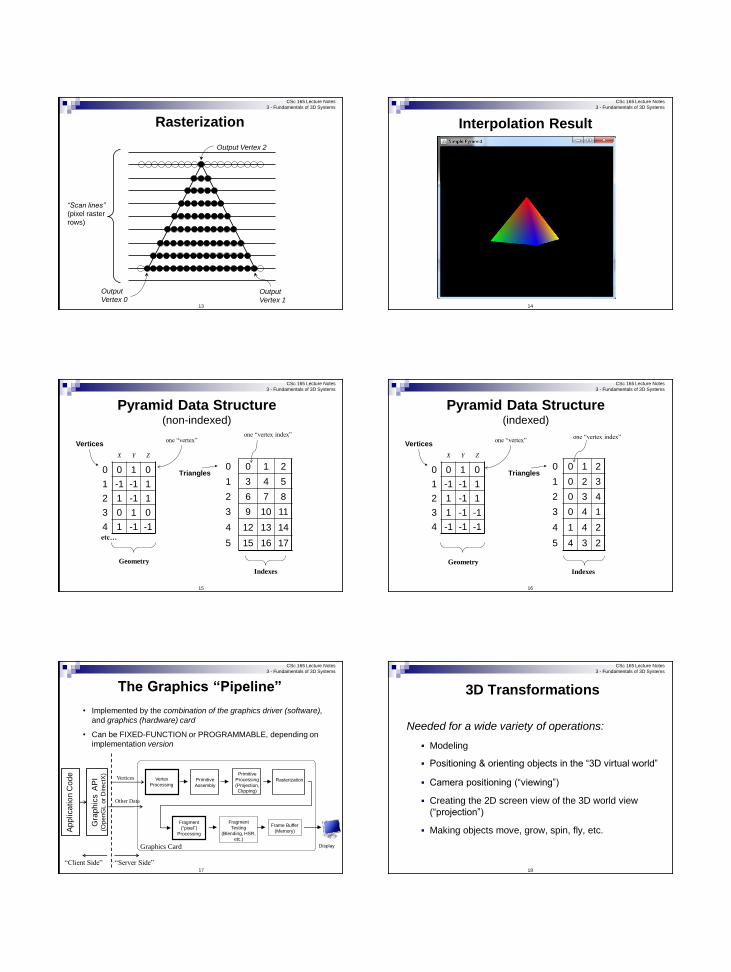
Rasterization
13
“Scan lines”
(pixel raster
rows)
Output
Vertex 0 Output
Vertex 1
Output Vertex 2
CSc 165 Lecture Notes
3 - Fundamentals of 3D Systems
Interpolation Result
14
CSc 165 Lecture Notes
3 - Fundamentals of 3D Systems
15
Pyramid Data Structure (non-indexed)
X Y Z
0 0 1 0
1 -1 -1 1
2 1 -1 1
3 0 1 0
4 1 -1 -1
Vertices
0 0 1 2
1 3 4 5
2 6 7 8
3 9 10 11
4 12 13 14
5 15 16 17
Triangles
Geometry
Indexes
one “vertex” one “vertex index”
etc…
CSc 165 Lecture Notes
3 - Fundamentals of 3D Systems
16
Pyramid Data Structure (indexed)
X Y Z
0 0 1 0
1 -1 -1 1
2 1 -1 1
3 1 -1 -1
4 -1 -1 -1
Vertices
0 0 1 2
1 0 2 3
2 0 3 4
3 0 4 1
4 1 4 2
5 4 3 2
Triangles
Geometry
Indexes
one “vertex” one “vertex index”
CSc 165 Lecture Notes
3 - Fundamentals of 3D Systems
17
The Graphics “Pipeline”
Vertex
Processing Primitive
Assembly Rasterization
Fragment
(“pixel”)
Processing
Fragment
Testing
(Blending, HSR, etc.)
Frame Buffer
(Memory)
Display
Primitive
Processing
(Projection, Clipping)
Graphics Card
• Implemented by the combination of the graphics driver (software),
and graphics (hardware) card
• Can be FIXED-FUNCTION or PROGRAMMABLE, depending on
implementation version
Vertices
Ap
plica
tio
n C
od
e
Gra
ph
ics A
PI
(OpenG
L o
r D
irectX
)
Other Data
“Client Side” “Server Side”
CSc 165 Lecture Notes
3 - Fundamentals of 3D Systems
18
3D Transformations
Needed for a wide variety of operations:
Modeling
Positioning & orienting objects in the “3D virtual world”
Camera positioning (“viewing”)
Creating the 2D screen view of the 3D world view
(“projection”)
Making objects move, grow, spin, fly, etc.

CSc 165 Lecture Notes
3 - Fundamentals of 3D Systems
19
Translation (column-major form):
1 0 0 Tx
0 1 0 Ty
0 0 1 Tz
0 0 0 1
* =
(x+Tx)
(y+Ty)
(z+Tz)
1
x
y
z
1
CSc 165 Lecture Notes
3 - Fundamentals of 3D Systems
20
Scaling (column-major form):
Sx 0 0 0
0 Sy 0 0
0 0 Sz 0
0 0 0 1
* =
(x*Sx)
(y*Sy)
(z*Sz)
1
x
y
z
1
CSc 165 Lecture Notes
3 - Fundamentals of 3D Systems
21
3D Rotation
• Recall 2D rotations can be “about any point”
o For simplicity we define only 2D rotation “about the origin”
o Other rotations require translation to/from the origin
• Similarly, 3D rotations can be “about any line” (any “axis of rotation”) :
Y
Z
X
Arbitrary
Point
“Axis of
Rotation”
CSc 165 Lecture Notes
3 - Fundamentals of 3D Systems
22
Euler’s Theorem
“Any rotation (or sequence of rotations) about a point is equivalent to a single rotation about some axis through that point.” [Leonard Euler, 1707-1783]
This is equivalent to saying:
Rotation about an arbitrary line through the origin can be accomplished by an equivalent set of rotations about the X, Y, and Z axes.
Thus we can rotate about an arbitrary axis as follows:
1. Translate the axis so it goes through the origin,
2. Rotate by the appropriate “Euler angles” about X, Y, and Z, and
3. “Undo” the translation
CSc 165 Lecture Notes
3 - Fundamentals of 3D Systems
23
Visualizing Euler’s Theorem
X
Y
Z
Axis of Rotation Desired point
rotation
“Euler angle” rotations to
accomplish desired rotation
CSc 165 Lecture Notes
3 - Fundamentals of 3D Systems
24
3D Rotation Transforms
Rotation about X by θ:
X
Y
Z
1
=
X’
Y’
Z’
1
1 0 0 0
0 cos θ -sin θ 0
0 sin θ cos θ 0
0 0 0 1

CSc 165 Lecture Notes
3 - Fundamentals of 3D Systems
25
Rotation about Y by θ:
X
Y
Z
1
=
X’
Y’
Z’
1
cos θ 0 sin θ 0
0 1 0 0
-sin θ 0 cos θ 0
0 0 0 1
CSc 165 Lecture Notes
3 - Fundamentals of 3D Systems
26
Rotation about Z by θ:
X
Y
Z
1
=
X’
Y’
Z’
1
cos θ -sin θ 0 0
sin θ cos θ 0 0
0 0 1 0
0 0 0 1
CSc 165 Lecture Notes
3 - Fundamentals of 3D Systems
27
Rotation in Angle/Axis Form
Rotation Axis = [ X Y Z ]
Rotation
Angle *
X Z
Y
* Positive rotation = CCW as seen from vector (axis)
head, looking toward tail at origin (right hand rule)
rotate(60, x, y, z)
CSc 165 Lecture Notes
3 - Fundamentals of 3D Systems
Representing Transforms
Package rml (“RAGE Math Library”)
Class Matrix4 : a 4x4 (“3D”) matrix
Methods for specifying translation, rotation, & scaling,
obtaining transpose and inverse, etc.
Similar to Java’s AffineTransform (but 3D)
Class Vector4 : a 4-element (“3D”) vector
Methods for most common vector operations: add,
dot- and cross-product, magnitude, normalize…
Useful for representing, for example, a rotation axis
28
CSc 165 Lecture Notes
3 - Fundamentals of 3D Systems
SceneNode Hierarchy Every object in a scene is an instance of SceneNode, which is a
ray.rage.scene.Node, which provides translate, rotate, and scale
matrices, or combined into a single “transform” matrix.
29
<<interface>>
Node
-localTransform : Matrix4
-worldTransform : Matrix4
etc...
+ translate(tx,ty,tz)
+ rotate(angle,axis)
etc...
<<interface>>
SceneNode
GenericSceneNode
Apply the specified
transform to the local matrix
Holds the transforms as
instances of class Transform
CSc 165 Lecture Notes
3 - Fundamentals of 3D Systems
30
“Perspective” matrix
q = 1 / tan(fieldOfView/2);
A = q / aspectRatio;
B = (near + far) / (near - far);
C = (2.0 * near * far) / (near - far);
The perspective transformation matrix is then:
A 0 0 0
0 q 0 0
0 0 B C
0 0 -1 0

CSc 165 Lecture Notes
3 - Fundamentals of 3D Systems
31
Lighting
Real world lights have a frequency spectrum
o White light: all (visible) frequencies
o Colored light: restricted frequency distribution
Simplified model:
Light “characteristics”
o Ambient, Diffuse, Specular “reflection characteristics”
o Red, Green, Blue “intensities”
Light “type”
o Positional, Directional, …
CSc 165 Lecture Notes
3 - Fundamentals of 3D Systems
The “ADS” lighting model
• Ambient reflection simulates a low-level illumination that equally
affects everything in the scene.
• Diffuse reflection brightens objects to various degree depending
on the light’s angle of incidence.
• Specular reflection conveys the shininess of an object by
strategically placing a highlight of appropriate size on the
object’s surface where light is reflected most directly towards
our eyes.
diffuse
specular
highlights
ambient
CSc 165 Lecture Notes
3 - Fundamentals of 3D Systems
33
Light Types
Point source
o Location, intensity
Directional (“distant”)
o Direction, intensity
Spot
o Location, direction, intensity, coneAngle, fallOffRate
θ
Ф
CSc 165 Lecture Notes
3 - Fundamentals of 3D Systems
34
RAGE Light Classes
<<interface>>
Light
name : String
Type : light.Type
ambient : [r g b a]
diffuse : [r g b a]
specular : [r g b a]
Range : float
fallOffExponent : float
etc.
GenericLight
<<interface>>
SceneObject
<<interface>>
Entity
<<interface>>
ManualObject
<<interface>>
Tessellation
<<interface>>
SkeletalEntity
CSc 165 Lecture Notes
3 - Fundamentals of 3D Systems
Materials
Models the reflectance characteristics of surfaces.
Usually modeled in ADS with four components:
• Ambient, Diffuse, and Specular
• Shininess (to determine size of specular
highlights)
CSc 165 Lecture Notes
3 - Fundamentals of 3D Systems
some common materials
Barradeu, N., http://www.barradeau.com/nicoptere/dump/materials.html

CSc 165 Lecture Notes
3 - Fundamentals of 3D Systems
ADS lighting computations
CSc 165 Lecture Notes
3 - Fundamentals of 3D Systems
θ
light
source
pixel
CSc 165 Lecture Notes
3 - Fundamentals of 3D Systems
Specular computation depends on the angle of
reflection of the light on the surface, and the viewing
angle of the eye.
θ
light
source
pixel
θ ϕ
CSc 165 Lecture Notes
3 - Fundamentals of 3D Systems
“Shininess” modeled with a falloff function.
Expresses how quickly the specular contribution reduces to
zero as the angle ϕ grows.
cos(ϕ)
cos2(ϕ)
cos3(ϕ)
cos50(ϕ)