performance evaluation of a portable 3d vision coordinate
TRANSCRIPT
Full Terms & Conditions of access and use can be found athttp://www.tandfonline.com/action/journalInformation?journalCode=taut20
AutomatikaJournal for Control, Measurement, Electronics, Computing andCommunications
ISSN: 0005-1144 (Print) 1848-3380 (Online) Journal homepage: http://www.tandfonline.com/loi/taut20
Performance evaluation of a portable 3D visioncoordinate measuring system
Octavio Icasio-Hernández, José-Joel González-Barbosa, Yajaira-Ilse Curiel-Razo & Juan B. Hurtado-Ramos
To cite this article: Octavio Icasio-Hernández, José-Joel González-Barbosa, Yajaira-Ilse Curiel-Razo & Juan B. Hurtado-Ramos (2017) Performance evaluation of a portable 3D vision coordinatemeasuring system, Automatika, 58:3, 253-265, DOI: 10.1080/00051144.2017.1391616
To link to this article: https://doi.org/10.1080/00051144.2017.1391616
© 2018 The Author(s). Published by InformaUK Limited, trading as Taylor & FrancisGroup.
Published online: 09 Feb 2018.
Submit your article to this journal
Article views: 224
View Crossmark data
brought to you by COREView metadata, citation and similar papers at core.ac.uk

REGULAR PAPER
Performance evaluation of a portable 3D vision coordinate measuring system
Octavio Icasio-Hern�andeza,b, Jos�e-Joel Gonz�alez-Barbosab, Yajaira-Ilse Curiel-Razob andJuan B. Hurtado-Ramosb
aCentro Nacional de Metrolog�ıa, CENAM, el Marqu�es, Mexico; bInstituto Polit�ecnico Nacional, CICATA Quer�etaro, Col Colinas del Cimatario,Mexico
ARTICLE HISTORYReceived 17 August 2017Accepted 4 October 2017
ABSTRACTIn this work, we present a portable 3D vision coordinate measuring machine (PCMM) for shortrange-real time photogrammetry. The PCMM performs 3D measurements of points using asingle camera in combination with a hand tool and a computer. The hand tool has infraredLEDs serving as photogrammetric targets. The positions of these targets were pre-calibratedwith an optical coordinate-measuring machine defining a local coordinate system on the handtool. The camera has an infrared filter to exclude all ambient light but infrared targets. Positionsof the imaged infrared targets are converted to 3D coordinates using pixel positions and pre-calibrated positions of the targets. Also, we present a set of criteria for selecting the infraredLEDs and the camera filter, a camera calibration method, a tracking and POSE algorithms, and a3D coordinate error correction for the PCMM. The correction is performed using the PCMM as arange meter, which implies comparing the 3D coordinate points of the PCMM with acoordinate measuring machine, and then generating a look up table (LUT) for correction. Theglobal error of the PCMM was evaluated under ASME B89.4.22-2004. Sphere and single pointerrors were around 1 mm, volumetric error were under 3 mm.
KEYWORDSPhotogrammetry; LUT;portable CMM ’sphere test;single point test; volumetrictest
1. Introduction
Opto-mechanical devices for dimensional and geo-metrical measurements have been present since closerange photogrammetry in industry became technicallyand economically successful in the mid-1980s (see[1]). The portable 3D vision coordinate measuringmachine (PCMM) is a perfect mechanical contactcomplement to a touchless optical measuring device,since it can measure objects that a touchless devicecannot reach, such as inner holes. Also, because of itsimportant applications, especially in the automotiveand aircraft industries, the PCMM must be as accurateas possible. In fact, the PCMM is broadly employedfor measuring large constructions, hidden points andcrash vehicles, among others. To measure PCMMaccuracy, the performance evaluation must be con-ducted based on specific standards, which is part ofthe goal of this paper.
Luhmann [1] and Hocken et al. [2] proposed exam-ples of opto-mechanical devices, such articulated armscoordinated measuring machines (AACMM), lasertrackers, photogrammetric systems and PCMM. Inthis work, we designed a PCMM using a camera, ahand tool with a spherical probe tip and optical targetson it, and a laptop computer (see Figure 1). PCMMdevices record trough the camera, the computer andthe optical targets, the 3D position of the sphericalprobe tip touching the object surface at points of
interest. References [2–7] report some designedPCMM. Commercial examples include SOLO system,by Metronor company, ATOS (including a hand toolaccessory), by GOM, MI probe, developed by Crea-form, and T-Point CS, by Steinbichler among others(see [1]). The way these commercial PCMMs work issimilar to how our own PCMM functions; however,their software and hardware components are not ofpublic domain.
Our idea of designing and building a PCMM aroseafter consulting Hocken et al. [2], Liu et al. [3] andAmdal [4]. As for the building process, we noticed thatHocken’s mathematical model to get 3D coordinateswas not accurate enough (results from using thismodel are discussed in Section 6 and Figure 7). Also,we noticed that Liu et al. [3] presented the same math-ematical model. They reported average errors in Zdirection under 0.26 mm with 450 mm depth travelwhen using the PCMM as a range meter, and after 50samples in average with almost 4 mm of dispersion.On the other hand, Amdal [4] described a generalmathematical model for perspective transformationsand demonstrated the repeatability of his PCMM mea-suring only one point at different distances. Amdal’sresults showed single point measurement errors below0.2 mm, yet the calibration method is not described.
Liu et al. [5] discussed the mathematical model forcalibrating the spherical probe tip center position of a
CONTACT Octavio Icasio-Hern�andez [email protected]
© 2018 The Author(s). Published by Informa UK Limited, trading as Taylor & Francis Group.This is an Open Access article distributed under the terms of the Creative Commons Attribution License (http://creativecommons.org/licenses/by/4.0/), which permits unrestricteduse, distribution, and reproduction in any medium, provided the original work is properly cited.
AUTOMATIKA, 2017VOL. 58, NO. 3, 253–265https://doi.org/10.1080/00051144.2017.1391616

PCMM. Our work is very similar to Liu et al.’s [5] asregards the number of targets; however, the probe tipof our PCMM is calibrated together with its targets,which impedes its change, unless a new calibration isperformed. Moreover, Li et al. [6] proposed a PCMMusing two cameras, since measurement errors reportedin their work and in Xiao et al. [7] suggested that twoor more cameras increased accuracy of a PCMM. Ourwork demonstrates that with a simple Look up Table(LUT), measurement errors decrease using only onecamera.
To develop our PCMM, we took as basis sugges-tions from [2–7] to design the hand tool, whereas weconsulted Lepetit et al. [8]’s mathematical model to getthe position and orientation (POSE) of the hand toolwith respect to the camera coordinate system. Othercomputer vision methods for getting the POSE areproposed in [9–16], yet these methods were excludedbecause the iteration process of their algorithms wastime consuming. As regards the camera calibration, werelied on Zhang’s technique [17], implemented byBouguet’s toolbox [18], yet additional and equally use-ful calibration methods are reported in [19–23].
The aim of this work is to propose a methodology toget a PCMM prototype for measuring 3D coordinates.Additionally, we describe a method for correcting these3D coordinates using a coordinate measuring machine(CMM) and a LUT. The correction allows for mea-surement errors below 1.2 mm when the hand tool isused as a range meter, which implies moving it withoutrotations toward or away from the camera (Z direc-tion), and below 0.5 mm when the hand tool is main-tained at a certain distance away from the camera, thusavoiding rotations. We evaluated the global measure-ment errors of the PCMM using ASME B89.4.22-2004standard (see [24]), considering the PCMM as anAACMM.
The remainder of this paper is organized as follows.Section 2 introduces our proposed PCMM, Section 3discusses the camera calibration method and Section 4describes the tracking and POSE algorithm, which arethe core of the PCMM. Then, Section 5 reports resultsfrom using the PCMM as a range meter and its perfor-mance evaluation, using ASME B89.4.22-2004 stan-dard. Finally, Section 6 presents our conclusions.
2. Proposed PCMM
Figure 1 depicts the proposed PCMM. It consists of aspecially designed hand tool, made of carbon fiber andaluminium, with a spherical probe tip and infraredLEDs on it, one CMOS camera and a laptop computer.The carbon fiber has a coefficient of thermal expan-sion close to zero, which avoids expansion and con-traction of the hand tool, thus reducing dimensionalerrors caused by temperature. Similarly, there are 10infrared LEDs on the hand tool, a touch trigger spheri-cal probe tip and a button. The button activates aBluetooth module sending a wireless signal to thecomputer to record the point where the probe tip ismaking contact. The 10 infrared light sources and theprobe tip must be referenced to a local hand tool coor-dinate system.
During measurements, the spherical probe tiptouches the object’s surface to be measured, and animage from the infrared light sources on the hand toolis captured with the camera and processed by a POSEalgorithm in the computer (see Figure 5(c)). As aresult, a 3D coordinate of the contact point on theobject’s surface is calculated. Section 4 explains indetail how to obtain the 3D coordinate point. Geomet-rical features of objects, such as dimensions, form, andposition errors among others can be evaluated withsoftware handling 3D point coordinates provided by
Figure 1. Proposed PCMM. (a) CMOS camera, (b) tripod, (c) computer, (d) spherical probe tip, (e) infrared LEDs, (f) Bluetooth mod-ule (g) and carbon fiber structure.
254 O. ICASIO-HERN�ANDEZ ET AL.
the PCMM, such as CMM measuring software. In thissense, the proposed PCMM is only a tool to collect 3Dcoordinate points.
2.1. Infrared filter and LEDs selection
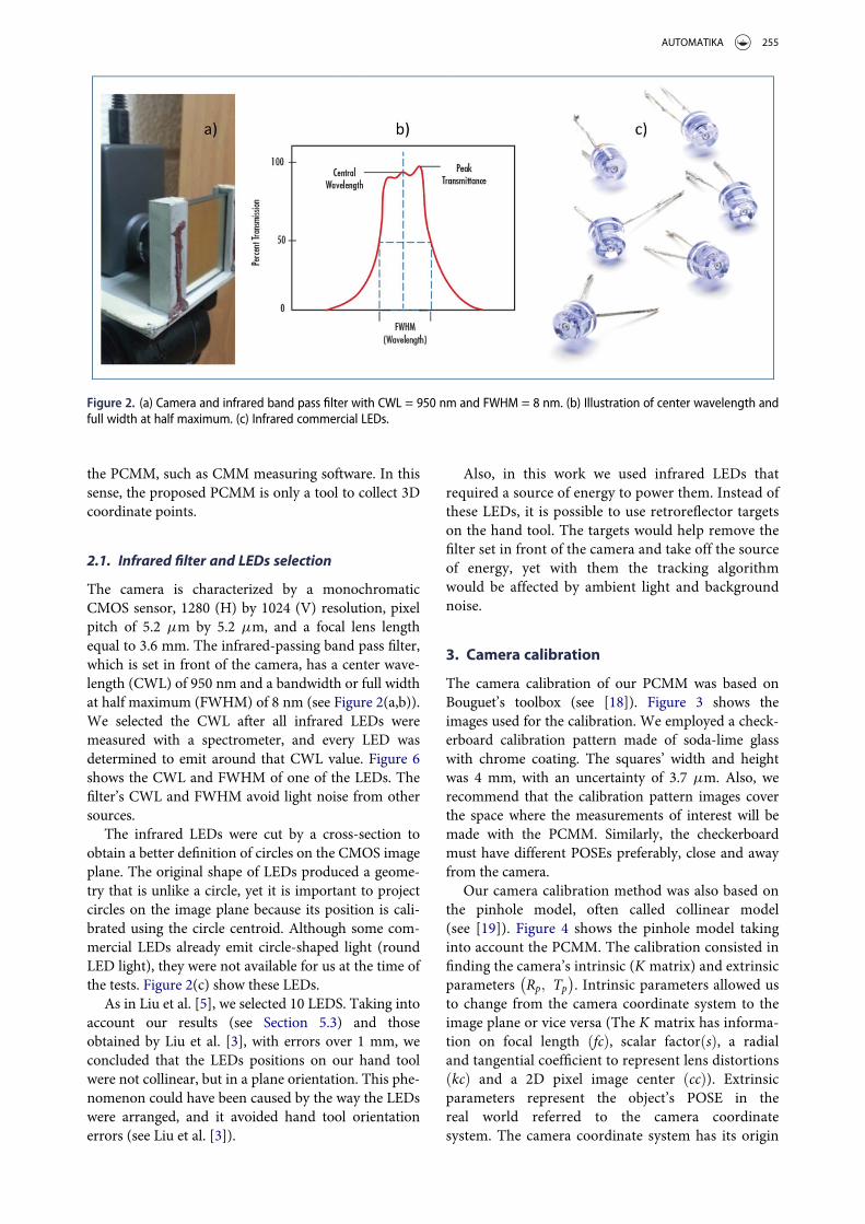
The camera is characterized by a monochromaticCMOS sensor, 1280 (H) by 1024 (V) resolution, pixelpitch of 5.2 mm by 5.2 mm, and a focal lens lengthequal to 3.6 mm. The infrared-passing band pass filter,which is set in front of the camera, has a center wave-length (CWL) of 950 nm and a bandwidth or full widthat half maximum (FWHM) of 8 nm (see Figure 2(a,b)).We selected the CWL after all infrared LEDs weremeasured with a spectrometer, and every LED wasdetermined to emit around that CWL value. Figure 6shows the CWL and FWHM of one of the LEDs. Thefilter’s CWL and FWHM avoid light noise from othersources.
The infrared LEDs were cut by a cross-section toobtain a better definition of circles on the CMOS imageplane. The original shape of LEDs produced a geome-try that is unlike a circle, yet it is important to projectcircles on the image plane because its position is cali-brated using the circle centroid. Although some com-mercial LEDs already emit circle-shaped light (roundLED light), they were not available for us at the time ofthe tests. Figure 2(c) show these LEDs.
As in Liu et al. [5], we selected 10 LEDS. Taking intoaccount our results (see Section 5.3) and thoseobtained by Liu et al. [3], with errors over 1 mm, weconcluded that the LEDs positions on our hand toolwere not collinear, but in a plane orientation. This phe-nomenon could have been caused by the way the LEDswere arranged, and it avoided hand tool orientationerrors (see Liu et al. [3]).
Also, in this work we used infrared LEDs thatrequired a source of energy to power them. Instead ofthese LEDs, it is possible to use retroreflector targetson the hand tool. The targets would help remove thefilter set in front of the camera and take off the sourceof energy, yet with them the tracking algorithmwould be affected by ambient light and backgroundnoise.
3. Camera calibration
The camera calibration of our PCMM was based onBouguet’s toolbox (see [18]). Figure 3 shows theimages used for the calibration. We employed a check-erboard calibration pattern made of soda-lime glasswith chrome coating. The squares’ width and heightwas 4 mm, with an uncertainty of 3.7 mm. Also, werecommend that the calibration pattern images coverthe space where the measurements of interest will bemade with the PCMM. Similarly, the checkerboardmust have different POSEs preferably, close and awayfrom the camera.
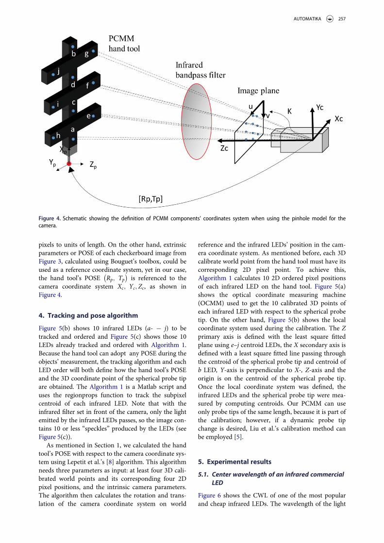
Our camera calibration method was also based onthe pinhole model, often called collinear model(see [19]). Figure 4 shows the pinhole model takinginto account the PCMM. The calibration consisted infinding the camera’s intrinsic (K matrix) and extrinsicparameters Rp; Tp
� �. Intrinsic parameters allowed us
to change from the camera coordinate system to theimage plane or vice versa (The K matrix has informa-tion on focal length fcð Þ, scalar factor sð Þ, a radialand tangential coefficient to represent lens distortionskcð Þ and a 2D pixel image center ccð Þ). Extrinsicparameters represent the object’s POSE in thereal world referred to the camera coordinatesystem. The camera coordinate system has its origin
Figure 2. (a) Camera and infrared band pass filter with CWL = 950 nm and FWHM = 8 nm. (b) Illustration of center wavelength andfull width at half maximum. (c) Infrared commercial LEDs.
AUTOMATIKA 255

at the point where the optical rays coming from thelens cross the optical axis, the Xc; Yc camera axis areparallel to the u; v axis of the image plane (seeFigure 4).
Intrinsic parameters do not change unless the cam-era’s focal length changes. In a PCMM, the cameraPOSE and focal length should be fixed. In the resultssection, we present the intrinsic parameters to convert
Figure 3. Sequence of images used for camera calibration.
256 O. ICASIO-HERN�ANDEZ ET AL.
pixels to units of length. On the other hand, extrinsicparameters or POSE of each checkerboard image fromFigure 3, calculated using Bouguet’s toolbox, could beused as a reference coordinate system, yet in our case,the hand tool’s POSE Rp; Tp
� �is referenced to the
camera coordinate system Xc; Yc;Zc, as shown inFigure 4.
4. Tracking and pose algorithm
Figure 5(b) shows 10 infrared LEDs (a- ¡ j) to betracked and ordered and Figure 5(c) shows those 10LEDs already tracked and ordered with Algorithm 1.Because the hand tool can adopt any POSE during theobjects’ measurement, the tracking algorithm and eachLED order will both define how the hand tool’s POSEand the 3D coordinate point of the spherical probe tipare obtained. The Algorithm 1 is a Matlab script anduses the regionprops function to track the subpixelcentroid of each infrared LED. Note that with theinfrared filter set in front of the camera, only the lightemitted by the infrared LEDs passes, so the image con-tains 10 or less “speckles” produced by the LEDs (seeFigure 5(c)).
As mentioned in Section 1, we calculated the handtool’s POSE with respect to the camera coordinate sys-tem using Lepetit et al.’s [8] algorithm. This algorithmneeds three parameters as input: at least four 3D cali-brated world points and its corresponding four 2Dpixel positions, and the intrinsic camera parameters.The algorithm then calculates the rotation and trans-lation of the camera coordinate system on world
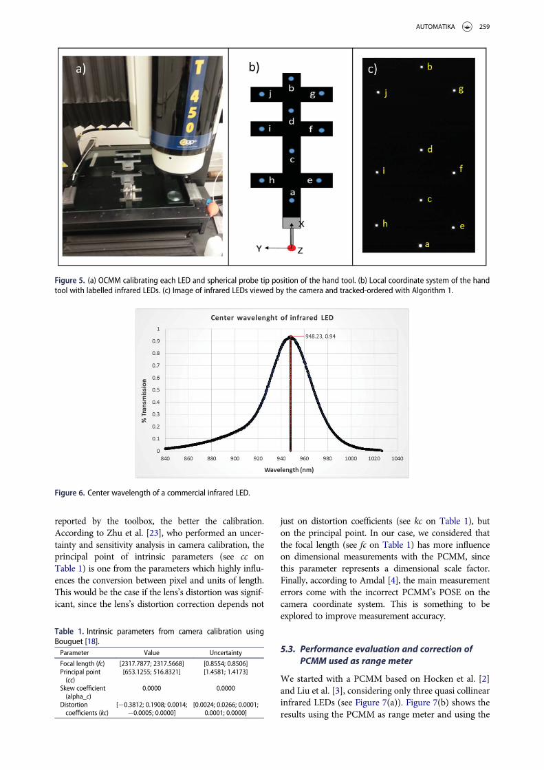
reference and the infrared LEDs’ position in the cam-era coordinate system. As mentioned before, each 3Dcalibrate world point from the hand tool must have itscorresponding 2D pixel point. To achieve this,Algorithm 1 calculates 10 2D ordered pixel positionsof each infrared LED on the hand tool. Figure 5(a)shows the optical coordinate measuring machine(OCMM) used to get the 10 calibrated 3D points ofeach infrared LED with respect to the spherical probetip. On the other hand, Figure 5(b) shows the localcoordinate system used during the calibration. The Zprimary axis is defined with the least square fittedplane using e–j centroid LEDs, the X secondary axis isdefined with a least square fitted line passing throughthe centroid of the spherical probe tip and centroid ofb LED, Y-axis is perpendicular to X-, Z-axis and theorigin is on the centroid of the spherical probe tip.Once the local coordinate system was defined, theinfrared LEDs and the spherical probe tip were mea-sured by computing centroids. Our PCMM can useonly probe tips of the same length, because it is part ofthe calibration; however, if a dynamic probe tipchange is desired, Liu et al.’s calibration method canbe employed [5].
5. Experimental results
5.1. Center wavelength of an infrared commercialLED
Figure 6 shows the CWL of one of the most popularand cheap infrared LEDs. The wavelength of the light
Figure 4. Schematic showing the definition of PCMM components’ coordinates system when using the pinhole model for thecamera.
AUTOMATIKA 257

emitted by the infrared LED was measured using aThorlab’s spectrometer. The peak value is approxi-mately on 948 nm, which is enclosed by the 8-nmbandwidth of the 950-nm infrared band pass filter setin front of the camera. The selection of the filterdepends on the LEDs’ wavelength. Figure 6 allowed usto select the infrared band pass filter.
5.2. Camera calibration
Table 1 shows the intrinsic parameters using imagesfrom Figure 3 as input parameters for Bouguet’s tool-box [18].
The quality of the calibration depends on the uncer-tainty of the parameters. The lower the uncertainty
Algorithm 1: LEDs tracking and ordering
f unction Cn½ � ¼ track_order Ið Þ%binary imageL ¼ logical » I < 255ð Þð Þ;%Start LEDs trackings ¼ regionprops L;
0PixelIdxList
0; 0PixelList
0� �;
%Compute subpixel intensity-weighted centroidsf or k ¼ 1 : numel sð Þidx ¼ s kð Þ:PixelIdxList;pv ¼ double I idxð Þð Þ;sumpv ¼ sum pvð Þ;x ¼ s kð Þ:PixelList :; 1ð Þ;y ¼ s kð Þ:PixelList :; 2ð Þ;xb ¼ sum x:� pvð Þ = sumpv;yb ¼ sum y: �pvð Þ = sumpv;C ¼ C; xb yb½ �;end%Start ordering centroids by computing a general centroid, cencen ¼ mean C 1; :ð Þð Þ;mean C 2; :ð Þð Þ½ �;%calculate distance of each centroid to cen and order centroids%in descending order using indexes calculated with distancesdr ¼ sqrt cen 1ð Þ � C 1; 1 : length Cð Þð Þð Þ:2 þ cen 2ð Þ � C 2; 1 : length Cð Þð Þð Þ:2ð Þ;dr_a; ia½ � ¼ sort dr; 0descend0ð Þ;Ca ¼ C :; iað Þ;%Accumulated distances between a point and the rest of the pointsda ¼ sqrt Ca 1; 1 : length Cð Þð Þ � Ca 1; 1ð Þð Þ:2 þ Ca 2; 1 : length Cð Þð Þ � Ca 2; 1ð Þð Þ:2ð Þ;%the next code ensures that a LED is the first point of vector Ca» ; ipb½ � ¼ max dað Þ;if ipb» ¼ 2aux ¼ Ca :; 2ð Þ;Ca :; 2ð Þ ¼ Ca :; ipbð Þ;Ca :; ipbð Þ ¼ aux;end%Evaluate a straight line between the first two elements of C (Points a, b of%Figure 5(b)). This gives us slope m and intersect b. Then, determine which points%are to the right or left of the straight line around 5 pixels that must be%enclosed to the line. There is an additional code (not here) to know whether%the points are over or under the straight line.m ¼ Ca 2; 1ð Þ � Ca 2; 2ð Þð Þ= Ca 1; 1ð Þ � Ca 1; 2ð Þð Þð Þ;b ¼ Ca 2; 1ð Þ � m�Ca 1; 1ð Þð Þ;mult ¼ 1;if m< 0 : mult ¼ -1;f or i ¼ 3 to length Cð Þyp ¼ m�Ca 1; ið Þ þ b;s ¼ yp� Ca 2; ið Þð Þ�mult;if s�� 5 and s�5 ind1 ¼ ind1 i½ �; %save index points c–dIf s> 5 : ind2 ¼ ind2 i½ �; %save index points e–gIf s< � 5 : ind3 ¼ ind3 i½ � ; %save index points h–jend%Discriminate between points c–d, e–g, h–j%order each index in ascending order with accumulated distancescd; ir½ � ¼ sort da ind1ð Þð Þ;ef g; ier½ � ¼ sort da ind2ð Þð Þ;hij; idr½ � ¼ sort da ind3ð Þð Þ;%f rom points on the straight line save c and diro ¼ ind1 irð Þ;%f rom points to the right of the straight line save; e; f ; giero ¼ ind2 ierð Þ;%f rom points to the lef t of the straight line save; h; i; jidro ¼ ind3 idrð Þ;%Reorder original centroidsCn ¼ Ca;if length iroð Þ ¼ ¼ 2 && length ieroð Þ ¼ ¼ 3 && length idroð Þ ¼ ¼ 3Cn :; 3 : 4ð Þ ¼ Ca :; iroð Þ;Cn :; 5 : 7ð Þ ¼ Ca :; ieroð Þ;Cn :; 8 : 10ð Þ ¼ Ca :; idroð Þ;end
258 O. ICASIO-HERN�ANDEZ ET AL.
reported by the toolbox, the better the calibration.According to Zhu et al. [23], who performed an uncer-tainty and sensitivity analysis in camera calibration, theprincipal point of intrinsic parameters (see cc onTable 1) is one from the parameters which highly influ-ences the conversion between pixel and units of length.This would be the case if the lens’s distortion was signif-icant, since the lens’s distortion correction depends not
just on distortion coefficients (see kc on Table 1), buton the principal point. In our case, we considered thatthe focal length (see fc on Table 1) has more influenceon dimensional measurements with the PCMM, sincethis parameter represents a dimensional scale factor.Finally, according to Amdal [4], the main measurementerrors come with the incorrect PCMM’s POSE on thecamera coordinate system. This is something to beexplored to improve measurement accuracy.
5.3. Performance evaluation and correction ofPCMM used as range meter
We started with a PCMM based on Hocken et al. [2]and Liu et al. [3], considering only three quasi collinearinfrared LEDs (see Figure 7(a)). Figure 7(b) shows theresults using the PCMM as range meter and using the
Figure 5. (a) OCMM calibrating each LED and spherical probe tip position of the hand tool. (b) Local coordinate system of the handtool with labelled infrared LEDs. (c) Image of infrared LEDs viewed by the camera and tracked-ordered with Algorithm 1.
Figure 6. Center wavelength of a commercial infrared LED.
Table 1. Intrinsic parameters from camera calibration usingBouguet [18].Parameter Value Uncertainty
Focal length (fc) [2317.7877; 2317.5668] [0.8554; 0.8506]Principal point(cc)
[653.1255; 516.8321] [1.4581; 1.4173]
Skew coefficient(alpha_c)
0.0000 0.0000
Distortioncoefficients (kc)
[¡0.3812; 0.1908; 0.0014;¡0.0005; 0.0000]
[0.0024; 0.0266; 0.0001;0.0001; 0.0000]
AUTOMATIKA 259

average of three measurements. Range meter means tomeasure using only one axis of the PCMM, avoidingrotations and translations in the other axis. FromFigure 7(b) to Figure 9, we can see range meter errorsin Z direction, which is the axis with less accuracy,since it measures the distance between the camera andthe hand tool.
The results obtained after correcting the PCMMwith a LUT are shown in Figure 7(b). The LUT wasevaluated following the next steps:
(1) Setup the PCMM as shown in Figure 8(a), wherethe PCMM is on the moving table of a CMM
and its movement allows for the PCMM’sZ-coordinate to increase or decrease.
(2) Align the PCMM’s coordinate systemXpcmm;Ypcmm;Zpcmm� �
against the CMM’s coor-dinate system Xcmm;Ycmm;Zcmmð Þ. This meansthat one axis of the CMM must be collinear withanother axis of the PCMM. In our case, thePCMM’s Z-axis was collinear with the CMM’sX-axis (see Figure 8(a)). Follow the next steps toperform the alignment:
(a)Move the CMM until the PCMM is in its ini-tial position as close to the camera as possible
Figure 7. (a) First prototype of PCMM. (b) Results using the PCMM as range meter in Z direction close and far away from the cameraafter LUT correction.
Figure 8. (a) Setup to use the PCMM as range meter. (b) Results of PCMM as range meter in Z-axis direction close and far away fromcamera after LUT correction.
260 O. ICASIO-HERN�ANDEZ ET AL.
(it depends on the range where the 10 handtool LEDs are in view to the camera).
(b)Make a translation of the camera until Xpcmm
and Ypcmm are close to zero.(c)Move the CMM to the end position of the
PCMM; this could be the range where themeasurements will be performed or the CMM’sscale interval.
(d)Rotate the camera until Xpcmm and Ypcmm areclose to zero.
(e) Repeat steps a–d until Xpcmm and Ypcmm areclose to zero during the whole CMM’s runpath.
Note: The camera must be set on a table or tripodfor translations and rotations. With a CMMwhere the entire bridge moves instead of thetable, it is recommended to rotate and translatethe coordinate system of the CMM to that ofthe PCMM.
(3) Stop the CMM at different positions, which willrepresent the first column positions of the LUT(we recommend at least five interval positionswhere the PCMM will measure). In each stopposition, evaluate PCMM errors (CMM positionminus PCMM position). These errors will be thesecond column of the LUT.
(4) Repeat steps 1–3 for X and Y PCMM coordi-nates; this will give us a LUT for each coordinate.
(5) Finally, an interpolation function will receive asinput parameters X; Y ; Z LUTs and the currentX; Y; Z position of the PCMM to perform thecorrection when the PCMM is measuring anobject. If the current PCMM position is notexactly on a column position of the LUT, a linear
interpolation is applied. If the current position ofthe PCMM is outside the LUT column positions,the first or last LUT error must be used for cor-rection. In our case, we did not perform extrapo-lation; instead, we fixed the errors on the LUT’sextremes.
Because of results presented in Figure 7(b), wereferred to Liu et al. [5] to propose a different proto-type using more infrared LEDs in different planes.Figure 8(a) shows the setup of this PCMM prototypeset in a CMM machine. Figure 8(b) shows the resultsusing the PCMM as range meter in Z direction andusing the average of three measurements. The Z Z-axisof Figure 8(b) shows the distance measurementreported by the CMM scales, minus PCMM; the ZZ-axis shows how far away the hand tool was from thecamera, covering from 750 to 1250 mm, approxi-mately.
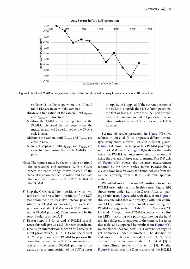
We added more LEDs on 3D positions to reducePCMM orientation errors. In this sense, Figure 8(b)shows errors under 1.2 mm in Z-axis. After compar-ing results from Figure 8(b) with those from Figure 7(b), we concluded that our prototype with non-collin-ear LEDs reduced measurement errors using thePCMM as range meter. In Table 1 from Section 4.2.1,Liu et al. [3] report poor PCMM accuracy with collin-ear LEDs measuring one point and moving the handtool in a different orientation to the camera. Based onthis table, and supported by results from Figure 7(b),we concluded that collinear LEDs were not enough toget accuracies under millimeters. The decision toadd more LEDs was consistent with Liu’s, whochanged from a collinear model in Liu et al. [3] toa non-collinear model in Liu et al. [5]. Finally,Figure 9 introduces the Z-axis errors of the PCMM
Figure 9. Results of PCMM as range meter in Z-axis direction close and far away from camera before LUT correction.
AUTOMATIKA 261
from Figure 8(a) before the LUT correction. Errorsshowed in Figure 8(b) confirmed that a simple LUTcorrection reduced the measurement errorconsiderably.
5.4. Performance evaluation of PCMM underASME B89.4.22-2004
A PCMM is similar to an AACMM, since both aremanual and portable instruments and the measure-ment range is similar. Moreover, both instruments getcoordinate system points in space referred to their ownbody; in the case of the AACMM, it is with respect toits base, whereas for the PCMM, it is referred to thecamera. To assess the performance of our PCMM, wethus referred to ASME B89.4.22-2004 [24], whodescribed a methodology for the performance evalua-tion of AACMM. The methodology includes threetests: the sphere test, the single point test and the vol-ume test.
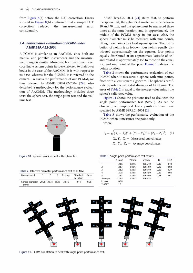
ASME B89.4.22-2004 [24] states that, to performthe sphere test, the sphere’s diameter must be between10 and 50 mm, and the sphere must be measured threetimes at the same location, and in approximately themiddle of the PCMM range in our case. Also, thesphere diameter must be measured with nine points,fitting these points to a least square sphere. The distri-bution of points is as follows: four points equally dis-tributed approximately on the equator, four pointsequally distributed at an approximate latitude of 45�
and rotated at approximately 45� to those on the equa-tor, and one point at the pole. Figure 10 shows thepoints location.
Table 2 shows the performance evaluation of ourPCMM when it measures a sphere with nine points,fitted with a least square algorithm. The sphere’s certif-icate reported a calibrated diameter of 19.98 mm. Theerror of Table 2 is equal to the average value minus thesphere’s calibrated value.
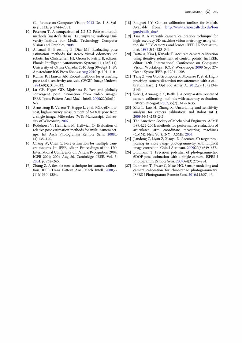
Figure 11 shows the positions used to deal with thesingle point performance test (SPAT). As can beobserved, we employed fewer positions than thosespecified by ASME B89.4.2.-2004 [24].
Table 3 shows the performance evaluation of thePCMM when it measures one point only:
where
Li ¼ffiffiffiffiffiffiffiffiffiffiffiffiffiffiffiffiffiffiffiffiffiffiffiffiffiffiffiffiffiffiffiffiffiffiffiffiffiffiffiffiffiffiffiffiffiffiffiffiffiffiffiffiffiffiffiffiffiffiffiffiffiffiffiffiffiffiffiffiffiffiffiffiffiXi � Xað Þ2 þ Yi � Yað Þ2 þ Zi � Zað Þ2
q; (1)
Xi;Yi; Zi ¼ Measured coordinates
Xa;Ya; Za ¼ Average coordinates
Figure 10. Sphere points to deal with sphere test.
Table 2. Effective diameter performance test of PCMM.Measurement 1 2 3 Average Standard
deviationError
Sphere diameter(mm)
20.78 20.31 21.18 20.76 0.44 0.78
Table 3. Single point performance test results.X (mm) Y (mm) Z (mm) Li Li^2
1 ¡2.86 83.96 1066.10 0.32 0.102 ¡2.87 84.06 1065.90 0.15 0.023 ¡2.82 83.93 1066.40 0.62 0.394 ¡2.78 83.95 1065.50 0.29 0.085 ¡2.93 83.95 1065.00 0.78 0.61Average ¡2.85 83.97 1065.78 1.21Li max 0.782sSPAT 1.1
Figure 11. PCMM orientation to deal with single point performance test.
262 O. ICASIO-HERN�ANDEZ ET AL.

2sSPAT ¼ 2
ffiffiffiffiffiffiffiffiffiffiffiffiffiffiffiPL2i
n� 1ð Þ
s(2)
2sSPAT = Single point articulation test.In the volumetric performance test, ASME B89
.4.22-2004 [24] specifies at least 20 positions of a ballbar with a known distance between balls. However,because of the range of our PCMM, we conducted thistest partially. In other words, we measured differentdistances between faces of a step gauge in X and Zdirections, whereas Y direction was excluded due tothe short PCMM’s range in this direction. Based on
the PCMM’s coordinate system, depicted in past fig-ures, the X X-axis had to be excluded, but an axischange transformation happened when we passedfrom the world to the camera system, thus causing thePCMM’s X X-axis to be transformed into the Y Y-axison the camera system.
Figure 12 shows the PCMM errors after measuringdistances between faces of a step gauge of 400 mmlong. The error reported in X X-axis of Figure 12 cor-responds to the difference between the calibrated face-to-face distance values of the step gauge and the face-to-face distance measured with the PCMM. The errorsrepresent the average of three measurements. Figure 12
Figure 12. Errors of the PCMM measuring in X-axis direction at different Z positions.
Figure 13. Errors of the PCMM measuring in Z-axis direction.
AUTOMATIKA 263

shows a minimum influence of Z position on thereported errors in the X X-axis direction. Figures 12and 13 present errors after LUT correction.
Figure 13 shows the PCMM errors in Z direction.This is the most critical direction of the PCMM, sinceit represented the distance between the camera and thehand tool. A hypothesis is that this direction andPCMM’s POSE (especially hand tool’s pitch and yawmovements) are the main source of errors.
6. Conclusions
In this paper, we proposed a PCMM. Note that toachieve proper geometrical shapes of circles, it isimportant to select appropriate LEDs. As regards theLED’s position calibration with the OCMM and LED’stracking, we used centroids as references, but an ellipsecontour may be preferred to avoid center locationerror (see [25]). Also, we selected a camera filter basedon the wavelength emitted by the infrared LEDs. Webelieve that the circle’s shape was influenced by the fil-ter placed in front of the camera, which is why weselected an infrared band pass filter with a CWL andband width covering the LEDs’ wavelength. The resultsobtained showed the emitted wavelength of a commer-cial infrared LED, which could be used as a referencevalue.
Any vision system used for dimensional measure-ments must perform camera calibration as the firststep. In this sense, we thought that a printed patterncould be enough for the camera calibration, as long asa subsequent correction is performed. Moreover,according to Tang et al. [21], lens distortion is not wellevaluated by Bouguet [18]. We will explore Tang’ssolution to see the influence of lens distortion on ourPCMMmeasurements.
Also, in this work we propose an algorithm to trackthe LEDs attached to the hand tool. This algorithm cantrack and order the LEDs to identify them, no matterthe hand tool’s POSE. LEDs’ order is an input parame-ter for the hand tool’s POSE. POSE consumes littleprocessing time not being iterative, but an accuracytest must be performed to know and correct the sour-ces of error.
Our first prototype for the PCMM with collinearLEDs did not achieve the accuracy we were looking for(under millimeters). We believed this accuracy losswas due to orientation errors not evaluated correctlywith collinear LEDs (see Table 1 of Liu et al. [3]).Therefore, we decided to modify the PCMM design,leading us to our initial goal. Also, according to Figures8(b) and Figure 9, if the PCMM was used as a rangemeter, we could calculate a LUT correction andincrease PCMM accuracy. We suggest using a CMM asa reference, but a step gauge or any other calibratedlengths could be used, although repeatability must beconsidered.
We evaluated the PCMM’s performance underASME B89.4.22-2004 standard, instead of developing anew, specific standard (see [1]). From the single pointtest, we concluded that a correct hand tool’s POSE iscrucial for small measurement errors (see [26–27]). Asregards the PCMM design, it can be strengthened byreplacing the aluminium part from the hand tool’sbody with a carbon-fiber-based one. Also, to reducethe hand tool’s weight and dimensions, the Bluetoothmodule may be placed with another device. As a finalremark for future work, we will test Lepetit’s algorithmunder controlled circumstances with dynamic butknown POSES. Lepetit’s algorithm is a key to prevent-ing the use of iterative sequences, thereby reducingcomputational cost.
Disclosure statement
No potential conflict of interest was reported by the authors.
Funding
We thank Instituto Polit�ecnico Nacional for its financial sup-port through project [grant number SIP-20160023] andCentro Nacional de Metrolog�ıa (CENAM) for the facilitiesgranted through SIDEPRO program.
References
[1] Luhmann T. Close range photogrammetry for indus-trial applications. ISPRS J Photogramm Remote Sens.2010;65(6):558–569.
[2] Hocken R, Pereira P. Coordinate measuring machinesand systems. 2nd ed. Boca Raton (FL): CRC Press;2011. Chapter 17, Non-Cartesian coordinate measur-ing systems; p. 495–497.
[3] Liu S, Huang F, Peng K. The modeling of portable 3Dvision coordinate measuring system. SPIE Opt DesTestII. 2005;5638:835–842.
[4] Amdal K. Single camera system for close range indus-trial photogrammetry. In: Lawrence W, James R,editors. XVIIth ISPRS Congress; 1992 Aug 2–14;Washington DC. Washington (DC): ISPRS; 1992.Vol. 29. p. 6–10.
[5] Liu S, Zhang H, Dong Y, et al. Portable light pen 3Dvision coordinate measuring system- probe tip centercalibration. Meas Sci Rev. 2013;13(4):194–199.
[6] Li J, Zhao H, Fu Q, et al. New 3D high-accuracy opticalcoordinates measuring technique based on an infraredtarget and binocular stereo vision. Proc. Opt Meas SystInd Insp. 2009;7389:738925–1–738925–11.
[7] Xiao Z, Jin L, Yu D, et al. A cross-target-based accuratecalibration method of binocular stereo systems withlarge-scale field-of-view. Meas J Int Meas Confedera-tion. 2010;43(6):747–754.
[8] Lepetit V, Moreno-Noguer F, Pascal F. EPnP: an accu-rate O (n) solution to the PnP problem. Int J ComputVis. 2009;81(2):155–166.
[9] Zheng Y, Kuang Y, Sugimoto S, et al. Revisiting thePnP problem: A fast, general and optimal solution. In:IEEE, editor. Proceedings of the IEEE International
264 O. ICASIO-HERN�ANDEZ ET AL.
Conference on Computer Vision; 2013 Dec 1–8. Syd-ney: IEEE. p. 2344–2351.
[10] Petersen T. A comparison of 2D-3D Pose estimationmethods [master’s thesis]. Lautrupvang: Aalborg Uni-versity-Institute for Media Technology ComputerVision and Graphics; 2008.
[11] Alismail H, Browning B, Dias MB. Evaluating poseestimation methods for stereo visual odometry onrobots. In: Christensen HI, Groen F, Petriu E, editors.Ebook: Intelligent Autonomous Systems 11 (IAS-11),University of Ottwa Canada; 2010 Aug 30–Sept 1; BGAmsterdam: IOS Press Ebooks; Aug 2010. p. 101–110.
[12] Kumar R, Hanson AR. Robust methods for estimatingpose and a sensitivity analysis. CVGIP Image Underst.1994;60(3):313–342.
[13] Lu CP, Hager GD, Mjolsness E. Fast and globallyconvergent pose estimation from video images.IEEE Trans Pattern Anal Mach Intell. 2000;22(6):610–622.
[14] Armstrong B, Verron T, Heppe L, et al. RGR-6D: low-cost, high-accuracy measurement of 6-DOF pose froma single image. Milwaukee (WI): Manuscript, Univer-sity of Wisconsin; 2007.
[15] Rodehorst V, Heinrichs M, Hellwich O. Evaluation ofrelative pose estimation methods for multi-camera set-ups. Int Arch Photogramm Remote Sens. 2008;0(3):135–140.
[16] Chang W, Chen C. Pose estimation for multiple cam-era systems. In: IEEE, editor. Proceedings of the 17thInternational Conference on Pattern Recognition 2004,ICPR 2004; 2004 Aug 26. Cambridge: IEEE. Vol. 3;2004. p. 262–265.
[17] Zhang Z. A flexible new technique for camera calibra-tion. IEEE Trans Pattern Anal Mach Intell. 2000;22(11):1330–1334.
[18] Bouguet J-Y. Camera calibration toolbox for Matlab.Available from: http://www.vision.caltech.edu/bouguetj/calib_doc/
[19] Tsai R. A versatile camera calibration technique forhigh-accuracy 3D machine vision metrology using off-the-shelf TV cameras and lenses. IEEE J Robot Auto-mat. 1987;3(4):323–344.
[20] Datta A, Kim J, Kanade T. Accurate camera calibrationusing iterative refinement of control points. In: IEEE,editor. 12th International Conference on ComputerVision Workshops, ICCV Workshops; 2009 Sept 27–Oct 4; Kyoto: IEEE. p. 1201–1208.
[21] Tang Z, von Gioi Grompone R, Monasse P, et al. High-precision camera distortion measurements with a cali-bration harp. J Opt Soc Amer A. 2012;29(10):2134–2143.
[22] Salvi J, Armangu�e X, Batlle J. A comparative review ofcamera calibrating methods with accuracy evaluation.Pattern Recognit. 2002;35(7):1617–1635.
[23] Zhu L, Luo H, Zhang X. Uncertainty and sensitivityanalysis for camera calibration. Ind Robot Int J.2009;36(3):238–243.
[24] The American Society of Mechanical Engineers. ASMEB89.4.22-2004: methods for performance evaluation ofarticulated arm coordinate measuring machines(CMM). New York (NY): ASME; 2004.
[25] Jiandong Z, Liyan Z, Xiaoyu D. Accurate 3D target posi-tioning in close range photogrammetry with implicitimage correction. Chin J Aeronaut. 2009;22(6):649–657.
[26] Luhmann T. Precision potential of photogrammetric6DOF pose estimation with a single camera. ISPRS JPhotogramm Remote Sens. 2009;64(3):275–284.
[27] Luhmann T, Fraser C, Maas HG. Sensor modelling andcamera calibration for close-range photogrammetry.ISPRS J Photogramm Remote Sens. 2016;115:37–46.
AUTOMATIKA 265