computational modeling of variable-droop leading … · computational modeling of variable-droop...
TRANSCRIPT
Computational Modeling of Variable-DroopLeading Edge in Forward Flight
Jeremy J. Bain,∗ Lakshmi N. Sankar,† J. V. R. Prasad,‡ and Oliver A. Bauchau§
Georgia Institute of Technology, Atlanta, Georgia 30332-0150
David A. Peters¶
Washington University, St. Louis, Missouri 63130
and
Chengjian He∗∗
Advanced Rotorcraft Technology, Inc., Mountain View, California 94035
DOI: 10.2514/1.39174
In recent years, there has been significant interest in on-blade concepts that expand the operating envelope of
helicopterswithout compromising the performance characteristics of the baseline rotor. The variable-droop leading-
edge concept is explored in amodified version of theNavier–Stokes solverOVERFLOW.Modificationsweremade to
the solver to allow deforming-grid capability. This concept was explored in dynamic stall tests of the VR-12 and
SC1095 helicopter airfoils. The variable-droop leading-edge airfoils have dramatically reduced drag and moment
rises associated with dynamic stall. Using the results of these tests, a modified UH-60A rotor incorporating variable-
droop leading-edge airfoils was analyzed using loosely coupled computational fluid dynamics and comprehensive
structural dynamics with OVERFLOW and DYMORE and compared with the standard UH-60A rotor for high-
thrust-case flight 9017. Results show a reduction in the peak negative pitching moment. The rotor efficiency was
shown to improve by 2.9% and the 4=rev component of vertical force reduced by 8%. These performance
improvements can be improvedwith an improved droop schedule and by incorporating improved transonic airfoils.
Nomenclature
CCM2 = section chordwise-force coefficient [C=�12�a2c�]
CMM2 = section pitching-moment coefficient [M=�12�a2c2�]
CNM2 = section normal-force coefficient [N=�12�a2c�]
CT = thrust coefficientc = chordk = reduced frequency (!c=2V1)L=De = rotor lift per equivalent drag [FZ=�FX �MZ�=V1�]r=R = nondimensional radiusVtip = rotor tip speed (�R)V1 = freestream velocity� = advance ratio (V1=Vtip)� = rotor solidity = rotor azimuth� = main rotor rotation rate, rad=s
I. Introduction
R ETREATING blade stall is a dominating factor in forwardflight and can limit the operational envelope of a helicopter. In
forward flight, the advancing blade encounters additional velocitydue to the freestream and the retreating blade encounters a reducedvelocity. This requires the same rotor span station to have good low-drag transonic and high-lift, low-speed performance. This represents
a significant design compromise that results in airfoils that havelower performance than airfoils designed for each flow environment.In moderate-speed cruise flight (�� 0:3), the advancing blade has3.45 times the dynamic pressure at the tip and 16 times at themidspan. To trim the aircraft, the lift generated on the advancing andretreating sides need to be balanced to avoid a large rolling moment.This requires the retreating blade to operate at or near its maximumlift capability while the advancing blade is at low or negativeincidence. This causes the blade to undergo dynamic stall cycles asthe blade goes from low to high incidence, causing large negativepitching moments, high vibration, and buffeting. The high negativepitching moment that occurs causes an elastic deformation thatcauses further pitch changes. These stall cycles limit the helicopter’smaximum flight speed, maneuverability, and thrust of the aircraft.
A number of on-blade concepts have been proposed that offertremendous potential for improved performance and reducedvibration for next-generation helicopters. These concepts attempt toimprove aerodynamics on the retreating side while limiting theiradverse effect on the advancing side. These include leading-edgeslats [1,2], trailing-edge flaps [3–5], variable camber [6], andleading-edge deformation [7,8]. A number of active controls wereapplied to an Apache-like rotor in forward flight by Yeo [9] usingCAMRAD II and modified airfoil tables. From these, the variable-droop leading edge (VDLE)was selected for further evaluation usingtwo- and three-dimensional computational tests. A variable-droopleading edge has been shown in two-dimensional tests to greatlyreduce the negative pitching-moment peak and peak drag, with smallchanges in lift in experimental and computational tests [10–12].
II. Numerical Methodology
A. OVERFLOW
The numerical simulations were done using the compressibleNavier–Stokes computational fluid dynamics (CFD) code OVER-FLOW [13]. OVERFLOW, developed by NASA, uses oversetstructured grids for a wide variety of problems, including rotorcraftsimulations [14,15]. Version 2.0ywithmodificationsmade under theDefense Advanced Research Projects Agency’s Helicopter QuietingProgram, as reported byDuque et al. [16],was usedwith elastic blademotion capability. For 2-D calculations, two different grids were
Presented as Paper 3872 at the 4th Flow Control Conference, Seattle, WA,23–26 June 2008; received 18 June 2008; accepted for publication 11October2008. Copyright © 2008 by the American Institute of Aeronautics andAstronautics, Inc. All rights reserved. Copies of this paper may be made forpersonal or internal use, on condition that the copier pay the $10.00 per-copyfee to the Copyright Clearance Center, Inc., 222 Rosewood Drive, Danvers,MA 01923; include the code 0021-8669/09 $10.00 in correspondence withthe CCC.
∗Research Engineer, Aerospace Engineering. Student Member AIAA.†Regents Professor, Aerospace Engineering. Associate Fellow AIAA.‡Professor, Aerospace Engineering. Associate Fellow AIAA.§Professor, Aerospace Engineering. Senior Member AIAA.¶Professor, Mechanical Engineering, Campus Box 1185. Fellow AIAA.∗∗Vice President, Research and Development, 1330 Charleston Road.
Senior Member AIAA.
JOURNAL OF AIRCRAFT
Vol. 46, No. 2, March–April 2009
617
generated. The first was a C-grid of dimensions 547 � 105, whichwas used with a y� of 1. The second grid modeled the wind-tunnelwalls with a smaller C-grid of dimensions 257 � 50 and a stretched119 � 62Cartesian grid similar to previousOVERFLOWruns in thiswind tunnel [17,18]. In dynamic stall tests, 35,000 time steps per loopwere usedwith 4Newton subiterations. Calculationsweremadewithup to 8 Newton subiterations and were found to produce nearidentical results. The solutions were run for 2–2.5 cycles usingfourth-order central differencing and the kinetic-eddy simulationturbulence model [19,20]. Three-dimensional runs were made usinga coarse 125 � 82 � 33 node UH-60A blade C-grid. The firstoffbody grid used spacing of 0.2 times the tip chord. The entire gridused approximately 4.6 million grid points. OVERFLOW used 20time steps per degree of azimuth, the detached-eddy simulation basedon the Spalart–Allmaras turbulence model [21,22], and fourth-ordercentral differencing.
B. OVERFLOW-DYMORE Coupling
For three-dimensional modeling, the UH-60A Blackhawk rotorwas used. Analysis of helicopter rotors in forward flight is a complexmultidisciplinary problem. Rotor blades are flexible beams thatundergo significant elastic deflection. To solve the elastic deflectionsand trim the rotor to the required thrust, rolling, and pitchingmoment, several comprehensive structural dynamics (CSD) codeshave been developed. The features and development history of thesecodes are summarized in [23]. They require the sectional structuralproperties of the rotor blade and details of the hub system. Theseproperties determine the elastic characteristics of the rotor andinteract with the aerodynamic forces. Accurate modeling of theaerodynamics of rotors is extremely challenging due to therequirement to model unsteady transonic flow with shocks, dynamicstall, reversed flows, and wakes. CSD codes rely on simplifiedaerodynamics from table lookups, stall models, and wake models.The aerodynamic calculations can be improved using a CFD code tosupplement the internal aerodynamic calculation through CFD-CSDcoupling, but at an approximately 2- or 3-order-of-magnitudeincrease in computational cost. Extensive work has been done on theUH-60A rotor using CFD-CSD coupling with a variety of solversthrough theUH-60AAirloads Program [24]. Potsdam et al. [25] usedloose coupling with OVERFLOW and CAMRAD II for a variety oflevel-flight conditions. OVERFLOW has also been used with otherstructural solvers, including RCAS [26] and DYMORE [16].
DYMORE [27] is a finite element solver that uses a multibodydynamics approach for themodeling of the rotor as a nonlinear elasticmultibody system. A four-bladed UH-60A rotor model is used thatincludes the blades, lag dampers, and push rods. A dynamic wake isused for the initial aerodynamics. An autopilot algorithm is used totrim the rotor to the prescribed thrust andmoment targets. Thismodelhas been used in previous studies using OVERFLOW [16] and GT-HYBRID [28]. No changes were made to the DYMORE model toaccount for the VDLE mechanical device.
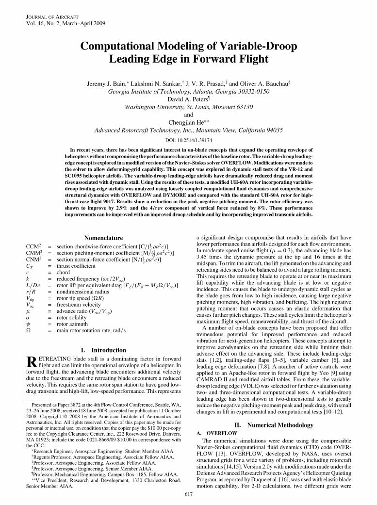
A loose-coupling trim method initially developed by Tung et al.[29] was used and shown in Fig. 1. DYMORE is first run usinglifting-line aerodynamics for several revolutions to obtain the trimsolution and blade motions. The elastic blade motions are thentransferred to OVERFLOW. The three forces and three moments inthe hub frame are then calculated by OVERFLOW. This avoids anydifferences in the local frame due to changes in chord length andorientation that occur when the leading edge is deformed. Airloadsand elastic deformationswere calculated at 81 rotor stations. Thefirstexchange of airloads from OVERFLOW to DYMORE took placeafter a periodic solutionwas obtained from two full rotor revolutions.Subsequent iterations passed airloads after two or three quarter-revolutions. Because airloads are exchanged at every degree ofazimuth, care is required to ensure that the OVERFLOW loads havereached periodicity, to avoid discontinuities. DYMORE uses theOVERFLOW loads and applies a small trim correction using table-lookup aerodynamics. Typically, 6–10 iterations are required toconverge to the desired thrust, rolling, and pitching moment.DYMORE ran for approximately 4 h per iteration.OVERFLOWwas
run on an 8-node 2.4 GHZ AMD Athlon processor cluster on 3–16processors. Approximately 8 h per revolution are required whenusing 16 processors.
C. Grid Deformation
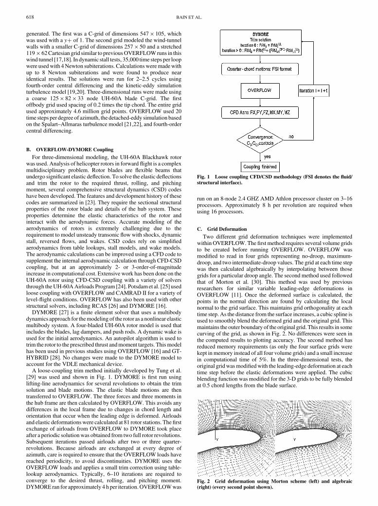
Two different grid deformation techniques were implementedwithin OVERFLOW. The first method requires several volume gridsto be created before running OVERFLOW. OVERFLOW wasmodified to read in four grids representing no-droop, maximum-droop, and two intermediate-droop values. The grid at each time stepwas then calculated algebraically by interpolating between thosegrids for a particular droop angle. The second method used followedthat of Morton et al. [30]. This method was used by previousresearchers for similar variable leading-edge deformations inOVERFLOW [11]. Once the deformed surface is calculated, thepoints in the normal direction are found by calculating the localnormal to the grid surface. This maintains grid orthogonality at eachtime step. As the distance from the surface increases, a cubic spline isused to smoothly blend the deformed grid and the original grid. Thismaintains the outer boundary of the original grid. This results in somecurving of the grid, as shown in Fig. 2. No differences were seen inthe computed results to plotting accuracy. The second method hasreduced memory requirements (as only the four surface grids werekept in memory instead of all four volume grids) and a small increasein computational time of 5%. In the three-dimensional tests, theoriginal gridwasmodifiedwith the leading-edge deformation at eachtime step before the elastic deformations were applied. The cubicblending function was modified for the 3-D grids to be fully blendedat 0.5 chord lengths from the blade surface.
Fig. 1 Loose coupling CFD/CSD methodology (FSI denotes the fluid/
structural interface).
Fig. 2 Grid deformation using Morton scheme (left) and algebraic
(right) (every second point shown).
618 BAIN ET AL.
III. Two-Dimensional Computations
To evaluate the grid deformation scheme in two dimensions,calculations were first done on a VR-12 airfoil with both fixed- andvariable-droop leading edges from the experiment of Chandrase-khara et al. [10]. This experiment used a VR-12 airfoil with up to a25 deg leading-edge droop from the quarter-chord. C-grids weremade forfixed-droop angles of 0, 5, 10, 15, and 20 deg by rotating theleading-edge down, as shown in Fig. 3. The experiment has twomildsteps near the hinge line, as the airfoil transitions between theleading-edge element, hinge, and main airfoil element resulted insome additional separation. The grid had a smooth upper surface anddid not have these transitions.
Typically, dynamic stall computations use a single grid to modelthe entire flowfield and apply freestream boundary conditions in thefar field. This yields good results when the wind tunnel has a high
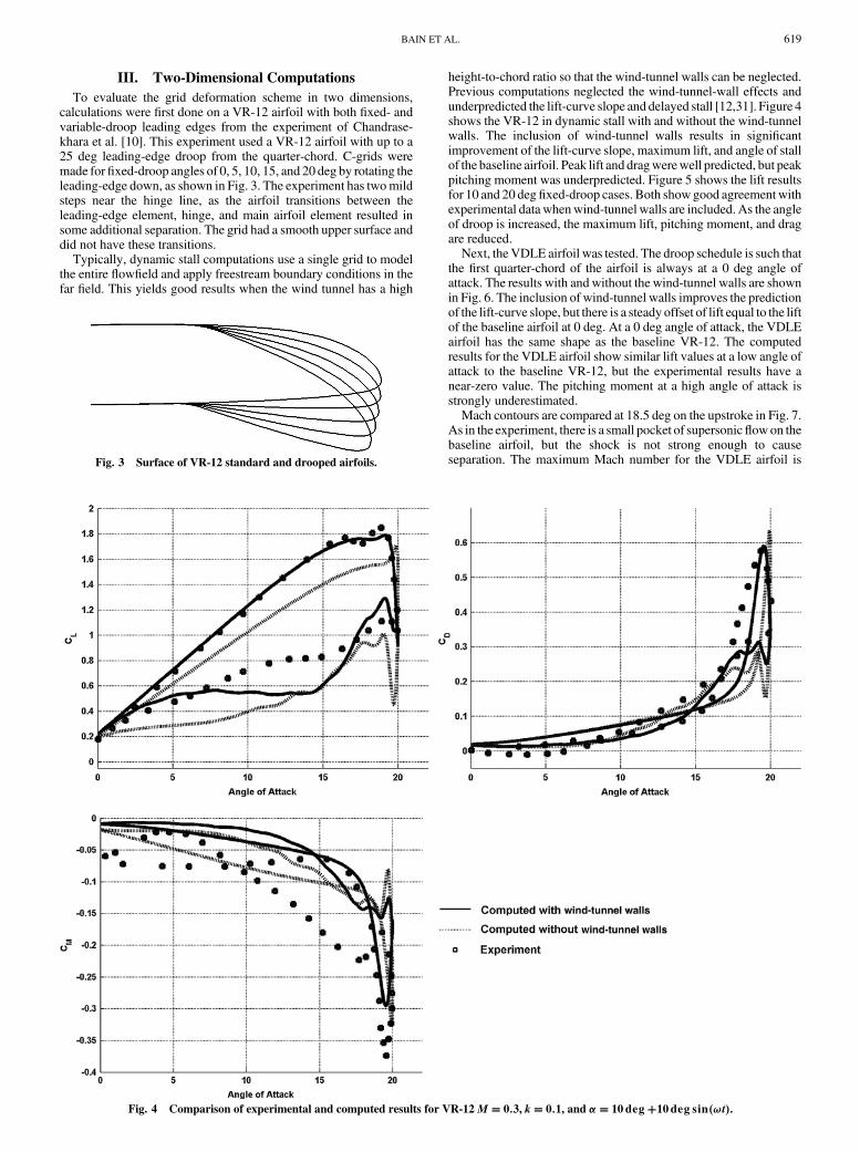
height-to-chord ratio so that the wind-tunnel walls can be neglected.Previous computations neglected the wind-tunnel-wall effects andunderpredicted the lift-curve slope and delayed stall [12,31]. Figure 4shows the VR-12 in dynamic stall with and without the wind-tunnelwalls. The inclusion of wind-tunnel walls results in significantimprovement of the lift-curve slope, maximum lift, and angle of stallof the baseline airfoil. Peak lift and dragwerewell predicted, but peakpitching moment was underpredicted. Figure 5 shows the lift resultsfor 10 and 20 degfixed-droop cases. Both showgood agreement withexperimental data whenwind-tunnel walls are included. As the angleof droop is increased, the maximum lift, pitching moment, and dragare reduced.
Next, the VDLE airfoil was tested. The droop schedule is such thatthe first quarter-chord of the airfoil is always at a 0 deg angle ofattack. The results with and without the wind-tunnel walls are shownin Fig. 6. The inclusion of wind-tunnel walls improves the predictionof the lift-curve slope, but there is a steady offset of lift equal to the liftof the baseline airfoil at 0 deg. At a 0 deg angle of attack, the VDLEairfoil has the same shape as the baseline VR-12. The computedresults for the VDLE airfoil show similar lift values at a low angle ofattack to the baseline VR-12, but the experimental results have anear-zero value. The pitching moment at a high angle of attack isstrongly underestimated.
Mach contours are compared at 18.5 deg on the upstroke in Fig. 7.As in the experiment, there is a small pocket of supersonicflowon thebaseline airfoil, but the shock is not strong enough to causeseparation. The maximum Mach number for the VDLE airfoil isFig. 3 Surface of VR-12 standard and drooped airfoils.
Fig. 4 Comparison of experimental and computed results for VR-12 M � 0:3, k� 0:1, and �� 10deg�10deg sin�!t�.
BAIN ET AL. 619
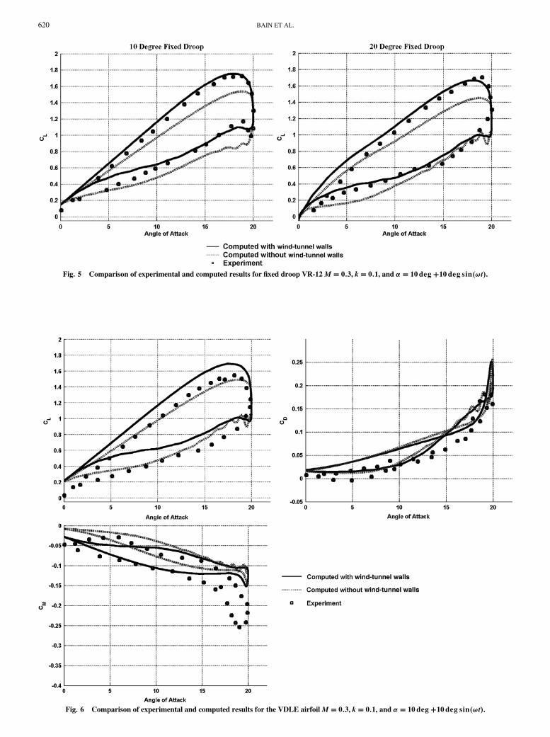
Fig. 5 Comparison of experimental and computed results for fixed droop VR-12 M � 0:3, k� 0:1, and �� 10deg�10deg sin�!t�.
Fig. 6 Comparison of experimental and computed results for the VDLE airfoil M � 0:3, k� 0:1, and �� 10deg�10deg sin�!t�.
620 BAIN ET AL.
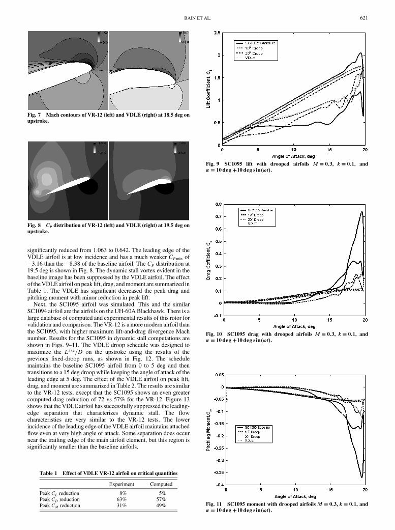
significantly reduced from 1.063 to 0.642. The leading edge of theVDLE airfoil is at low incidence and has a much weaker CPmin of�3:16 than the �8:38 of the baseline airfoil. The CP distribution at19.5 deg is shown in Fig. 8. The dynamic stall vortex evident in thebaseline image has been suppressed by the VDLE airfoil. The effectof theVDLE airfoil on peak lift, drag, andmoment are summarized inTable 1. The VDLE has significant decreased the peak drag andpitching moment with minor reduction in peak lift.
Next, the SC1095 airfoil was simulated. This and the similarSC1094 airfoil are the airfoils on the UH-60ABlackhawk. There is alarge database of computed and experimental results of this rotor forvalidation and comparison. The VR-12 is a more modern airfoil thanthe SC1095, with higher maximum lift-and-drag divergence Machnumber. Results for the SC1095 in dynamic stall computations areshown in Figs. 9–11. The VDLE droop schedule was designed tomaximize the L3=2=D on the upstroke using the results of theprevious fixed-droop runs, as shown in Fig. 12. The schedulemaintains the baseline SC1095 airfoil from 0 to 5 deg and thentransitions to a 15 deg droop while keeping the angle of attack of theleading edge at 5 deg. The effect of the VDLE airfoil on peak lift,drag, and moment are summarized in Table 2. The results are similarto the VR-12 tests, except that the SC1095 shows an even greatercomputed drag reduction of 72 vs 57% for the VR-12. Figure 13shows that theVDLE airfoil has successfully suppressed the leading-edge separation that characterizes dynamic stall. The flowcharacteristics are very similar to the VR-12 tests. The lowerincidence of the leading edge of the VDLE airfoil maintains attachedflow even at very high angle of attack. Some separation does occurnear the trailing edge of the main airfoil element, but this region issignificantly smaller than the baseline airfoils.
Fig. 7 Mach contours of VR-12 (left) and VDLE (right) at 18.5 deg onupstroke.
Fig. 8 CP distribution of VR-12 (left) and VDLE (right) at 19.5 deg on
upstroke.
Table 1 Effect of VDLE VR-12 airfoil on critical quantities
Experiment Computed
Peak CL reduction 8% 5%Peak CD reduction 63% 57%Peak CM reduction 31% 49%
Fig. 9 SC1095 lift with drooped airfoils M � 0:3, k� 0:1, and�� 10deg�10deg sin�!t�.
Fig. 10 SC1095 drag with drooped airfoils M � 0:3, k� 0:1, and
�� 10deg�10deg sin�!t�.
Fig. 11 SC1095 moment with drooped airfoils M � 0:3, k� 0:1, and�� 10deg�10deg sin�!t�.
BAIN ET AL. 621
IV. UH60A-Based Computations
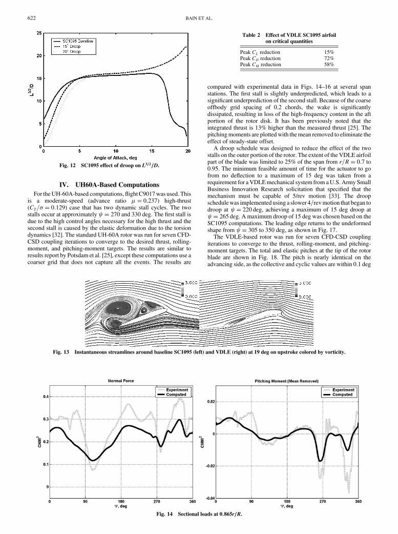
For theUH-60A-based computations,flight C9017was used. Thisis a moderate-speed (advance ratio �� 0:237) high-thrust(CT=� � 0:129) case that has two dynamic stall cycles. The twostalls occur at approximately � 270 and 330 deg. The first stall isdue to the high control angles necessary for the high thrust and thesecond stall is caused by the elastic deformation due to the torsiondynamics [32]. The standard UH-60A rotor was run for seven CFD-CSD coupling iterations to converge to the desired thrust, rolling-moment, and pitching-moment targets. The results are similar toresults report by Potsdam et al. [25], except these computations use acoarser grid that does not capture all the events. The results are
compared with experimental data in Figs. 14–16 at several spanstations. The first stall is slightly underpredicted, which leads to asignificant underprediction of the second stall. Because of the coarseoffbody grid spacing of 0.2 chords, the wake is significantlydissipated, resulting in loss of the high-frequency content in the aftportion of the rotor disk. It has been previously noted that theintegrated thrust is 13% higher than the measured thrust [25]. Thepitchingmoments are plottedwith themean removed to eliminate theeffect of steady-state offset.
A droop schedule was designed to reduce the effect of the twostalls on the outer portion of the rotor. The extent of the VDLE airfoilpart of the blade was limited to 25% of the span from r=R� 0:7 to0.95. The minimum feasible amount of time for the actuator to gofrom no deflection to a maximum of 15 deg was taken from arequirement for aVDLEmechanical system from aU.S. Army SmallBusiness Innovation Research solicitation that specified that themechanism must be capable of 5/rev motion [33]. The droopschedulewas implemented using a slower 4=revmotion that began todroop at � 220 deg, achieving a maximum of 15 deg droop at � 265 deg. A maximum droop of 15 deg was chosen based on theSC1095 computations. The leading edge returns to the undeformedshape from � 305 to 350 deg, as shown in Fig. 17.
The VDLE-based rotor was run for seven CFD-CSD couplingiterations to converge to the thrust, rolling-moment, and pitching-moment targets. The total and elastic pitches at the tip of the rotorblade are shown in Fig. 18. The pitch is nearly identical on theadvancing side, as the collective and cyclic values are within 0.1 deg
Fig. 12 SC1095 effect of droop on L3=2=D.
Table 2 Effect of VDLE SC1095 airfoil
on critical quantities
Peak CL reduction 15%Peak CD reduction 72%Peak CM reduction 58%
Fig. 13 Instantaneous streamlines around baseline SC1095 (left) and VDLE (right) at 19 deg on upstroke colored by vorticity.
Fig. 14 Sectional loads at 0:865r=R.
622 BAIN ET AL.
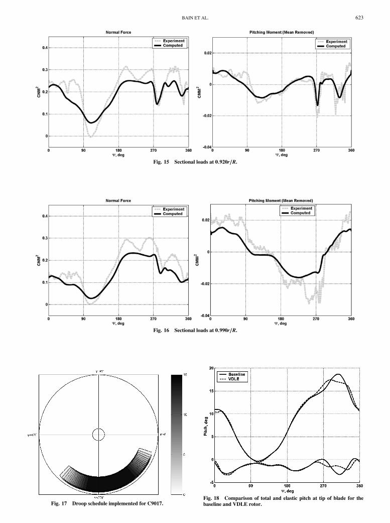
Fig. 15 Sectional loads at 0:920r=R.
Fig. 16 Sectional loads at 0:990r=R.
Fig. 17 Droop schedule implemented for C9017.Fig. 18 Comparison of total and elastic pitch at tip of blade for the
baseline and VDLE rotor.
BAIN ET AL. 623
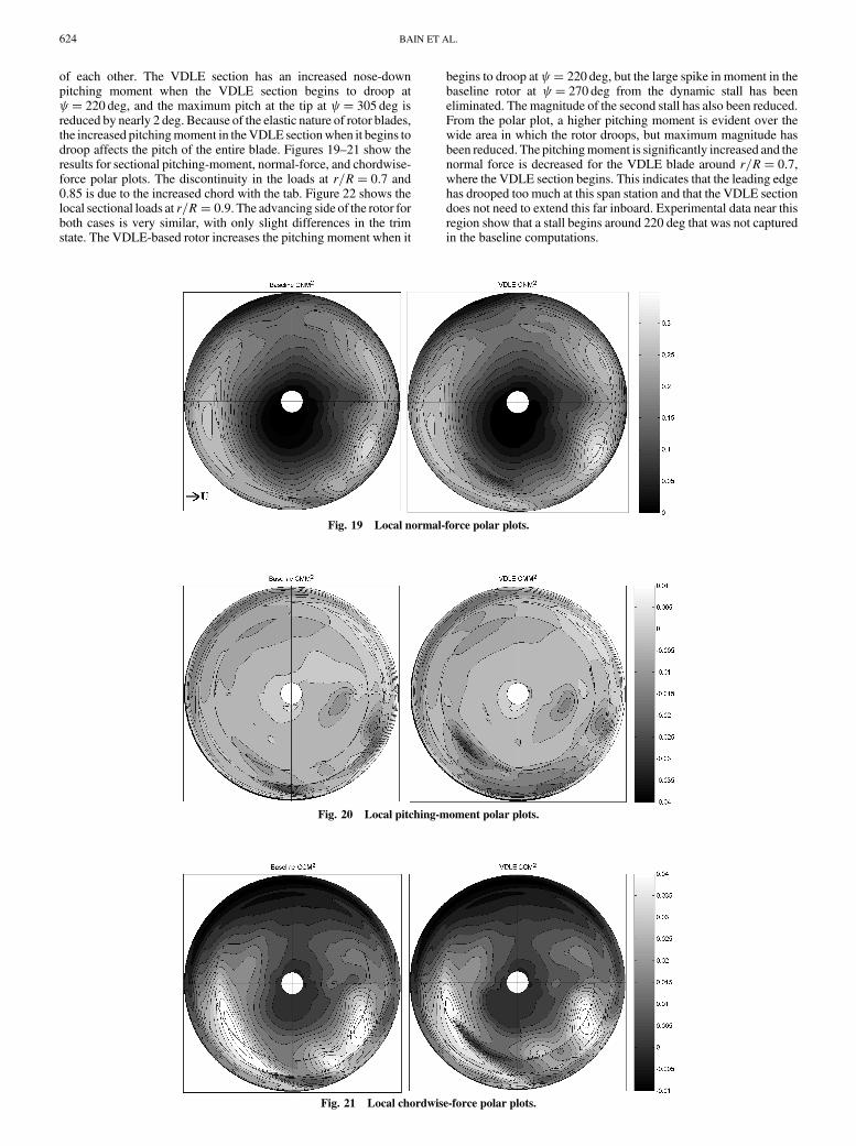
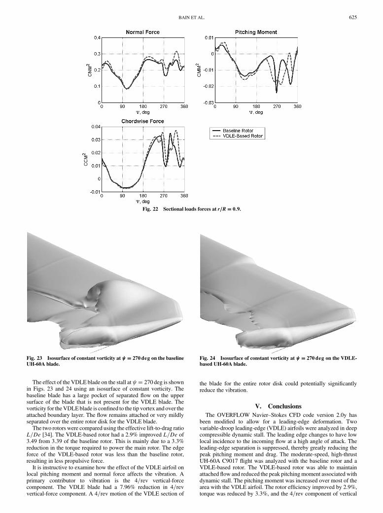
of each other. The VDLE section has an increased nose-downpitching moment when the VDLE section begins to droop at � 220 deg, and the maximum pitch at the tip at � 305 deg isreduced by nearly 2 deg. Because of the elastic nature of rotor blades,the increased pitchingmoment in theVDLE sectionwhen it begins todroop affects the pitch of the entire blade. Figures 19–21 show theresults for sectional pitching-moment, normal-force, and chordwise-force polar plots. The discontinuity in the loads at r=R� 0:7 and0.85 is due to the increased chord with the tab. Figure 22 shows thelocal sectional loads at r=R� 0:9. The advancing side of the rotor forboth cases is very similar, with only slight differences in the trimstate. The VDLE-based rotor increases the pitching moment when it
begins to droop at � 220 deg, but the large spike in moment in thebaseline rotor at � 270 deg from the dynamic stall has beeneliminated. The magnitude of the second stall has also been reduced.From the polar plot, a higher pitching moment is evident over thewide area in which the rotor droops, but maximum magnitude hasbeen reduced. The pitchingmoment is significantly increased and thenormal force is decreased for the VDLE blade around r=R� 0:7,where the VDLE section begins. This indicates that the leading edgehas drooped too much at this span station and that the VDLE sectiondoes not need to extend this far inboard. Experimental data near thisregion show that a stall begins around 220 deg that was not capturedin the baseline computations.
Fig. 19 Local normal-force polar plots.
Fig. 20 Local pitching-moment polar plots.
Fig. 21 Local chordwise-force polar plots.
624 BAIN ET AL.
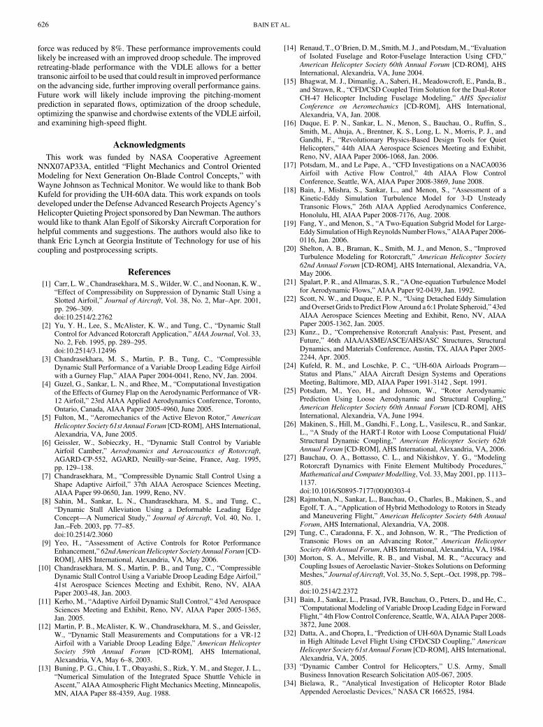
The effect of the VDLE blade on the stall at � 270 deg is shownin Figs. 23 and 24 using an isosurface of constant vorticity. Thebaseline blade has a large pocket of separated flow on the uppersurface of the blade that is not present for the VDLE blade. Thevorticity for theVDLEblade is confined to the tip vortex and over theattached boundary layer. The flow remains attached or very mildlyseparated over the entire rotor disk for the VDLE blade.
The two rotors were compared using the effective lift-to-drag ratioL=De [34]. The VDLE-based rotor had a 2.9% improved L=De of3.49 from 3.39 of the baseline rotor. This is mainly due to a 3.3%reduction in the torque required to power the main rotor. The edgeforce of the VDLE-based rotor was less than the baseline rotor,resulting in less propulsive force.
It is instructive to examine how the effect of the VDLE airfoil onlocal pitching moment and normal force affects the vibration. Aprimary contributor to vibration is the 4=rev vertical-forcecomponent. The VDLE blade had a 7.96% reduction in 4=revvertical-force component. A 4=rev motion of the VDLE section of
the blade for the entire rotor disk could potentially significantlyreduce the vibration.
V. Conclusions
The OVERFLOW Navier–Stokes CFD code version 2.0y hasbeen modified to allow for a leading-edge deformation. Twovariable-droop leading-edge (VDLE) airfoils were analyzed in deepcompressible dynamic stall. The leading edge changes to have lowlocal incidence to the incoming flow at a high angle of attack. Theleading-edge separation is suppressed, thereby greatly reducing thepeak pitching moment and drag. The moderate-speed, high-thrustUH-60A C9017 flight was analyzed with the baseline rotor and aVDLE-based rotor. The VDLE-based rotor was able to maintainattached flow and reduced the peak pitching moment associated withdynamic stall. The pitching moment was increased over most of thearea with the VDLE airfoil. The rotor efficiency improved by 2.9%,torque was reduced by 3.3%, and the 4=rev component of vertical
Fig. 22 Sectional loads forces at r=R� 0:9.
Fig. 23 Isosurface of constant vorticity at � 270deg on the baseline
UH-60A blade.
Fig. 24 Isosurface of constant vorticity at � 270deg on the VDLE-
based UH-60A blade.
BAIN ET AL. 625
force was reduced by 8%. These performance improvements couldlikely be increased with an improved droop schedule. The improvedretreating-blade performance with the VDLE allows for a bettertransonic airfoil to be used that could result in improved performanceon the advancing side, further improving overall performance gains.Future work will likely include improving the pitching-momentprediction in separated flows, optimization of the droop schedule,optimizing the spanwise and chordwise extents of the VDLE airfoil,and examining high-speed flight.
Acknowledgments
This work was funded by NASA Cooperative AgreementNNX07AP33A, entitled “Flight Mechanics and Control OrientedModeling for Next Generation On-Blade Control Concepts,” withWayne Johnson as Technical Monitor. We would like to thank BobKufeld for providing the UH-60A data. This work expands on toolsdeveloped under the Defense Advanced Research Projects Agency’sHelicopter Quieting Project sponsored byDanNewman. The authorswould like to thank Alan Egolf of Sikorsky Aircraft Corporation forhelpful comments and suggestions. The authors would also like tothank Eric Lynch at Georgia Institute of Technology for use of hiscoupling and postprocessing scripts.
References
[1] Carr, L.W., Chandrasekhara,M. S.,Wilder,W. C., andNoonan, K.W.,“Effect of Compressibility on Suppression of Dynamic Stall Using aSlotted Airfoil,” Journal of Aircraft, Vol. 38, No. 2, Mar–Apr. 2001,pp. 296–309.doi:10.2514/2.2762
[2] Yu, Y. H., Lee, S., McAlister, K. W., and Tung, C., “Dynamic StallControl for Advanced Rotorcraft Application,” AIAA Journal, Vol. 33,No. 2, Feb. 1995, pp. 289–295.doi:10.2514/3.12496
[3] Chandrasekhara, M. S., Martin, P. B., Tung, C., “CompressibleDynamic Stall Performance of a Variable Droop Leading Edge Airfoilwith a Gurney Flap,” AIAA Paper 2004-0041, Reno, NV, Jan. 2004.
[4] Guzel, G., Sankar, L. N., and Rhee, M., “Computational Investigationof the Effects of Gurney Flap on the Aerodynamic Performance of VR-12 Airfoil,” 23rd AIAA Applied Aerodynamics Conference, Toronto,Ontario, Canada, AIAA Paper 2005-4960, June 2005.
[5] Fulton, M., “Aeromechanics of the Active Elevon Rotor,” American
Helicopter Society 61st Annual Forum [CD-ROM], AHS International,Alexandria, VA, June 2005.
[6] Geissler, W., Sobieczky, H., “Dynamic Stall Control by VariableAirfoil Camber,” Aerodynamics and Aeroacoustics of Rotorcraft,AGARD-CP-552, AGARD, Neuilly-sur-Seine, France, Aug. 1995,pp. 129–138.
[7] Chandrasekhara, M., “Compressible Dynamic Stall Control Using aShape Adaptive Airfoil,” 37th AIAA Aerospace Sciences Meeting,AIAA Paper 99-0650, Jan. 1999, Reno, NV.
[8] Sahin, M., Sankar, L. N., Chandrasekhara, M. S., and Tung, C.,“Dynamic Stall Alleviation Using a Deformable Leading EdgeConcept—A Numerical Study,” Journal of Aircraft, Vol. 40, No. 1,Jan.–Feb. 2003, pp. 77–85.doi:10.2514/2.3060
[9] Yeo, H., “Assessment of Active Controls for Rotor PerformanceEnhancement,” 62ndAmericanHelicopter Society Annual Forum [CD-ROM], AHS International, Alexandria, VA, May 2006.
[10] Chandrasekhara, M. S., Martin, P. B., and Tung, C., “CompressibleDynamic Stall Control Using a Variable Droop Leading Edge Airfoil,”41st Aerospace Sciences Meeting and Exhibit, Reno, NV, AIAAPaper 2003-48, Jan. 2003.
[11] Kerho, M., “Adaptive Airfoil Dynamic Stall Control,” 43rd AerospaceSciences Meeting and Exhibit, Reno, NV, AIAA Paper 2005-1365,Jan. 2005.
[12] Martin, P. B., McAlister, K. W., Chandrasekhara, M. S., and Geissler,W., “Dynamic Stall Measurements and Computations for a VR-12Airfoil with a Variable Droop Leading Edge,” American Helicopter
Society 59th Annual Forum [CD-ROM], AHS International,Alexandria, VA, May 6–8, 2003.
[13] Buning, P. G., Chiu, I. T., Obayashi, S., Rizk, Y. M., and Steger, J. L.,“Numerical Simulation of the Integrated Space Shuttle Vehicle inAscent,” AIAA Atmospheric Flight Mechanics Meeting, Minneapolis,MN, AIAA Paper 88-4359, Aug. 1988.
[14] Renaud, T.,O’Brien,D.M., Smith,M. J., andPotsdam,M., “Evaluationof Isolated Fuselage and Rotor-Fuselage Interaction Using CFD,”American Helicopter Society 60th Annual Forum [CD-ROM], AHSInternational, Alexandria, VA, June 2004.
[15] Bhagwat, M. J., Dimanlig, A., Saberi, H., Meadowcroft, E., Panda, B.,and Strawn, R., “CFD/CSD Coupled Trim Solution for the Dual-RotorCH-47 Helicopter Including Fuselage Modeling,” AHS Specialist
Conference on Aeromechanics [CD-ROM], AHS International,Alexandria, VA, Jan. 2008.
[16] Duque, E. P. N., Sankar, L. N., Menon, S., Bauchau, O., Ruffin, S.,Smith, M., Ahuja, A., Brentner, K. S., Long, L. N., Morris, P. J., andGandhi, F., “Revolutionary Physics-Based Design Tools for QuietHelicopters,” 44th AIAA Aerospace Sciences Meeting and Exhibit,Reno, NV, AIAA Paper 2006-1068, Jan. 2006.
[17] Potsdam, M., and Le Pape, A., “CFD Investigations on a NACA0036Airfoil with Active Flow Control,” 4th AIAA Flow ControlConference, Seattle, WA, AIAA Paper 2008-3869, June 2008.
[18] Bain, J., Mishra, S., Sankar, L., and Menon, S., “Assessment of aKinetic-Eddy Simulation Turbulence Model for 3-D UnsteadyTransonic Flows,” 26th AIAA Applied Aerodynamics Conference,Honolulu, HI, AIAA Paper 2008-7176, Aug. 2008.
[19] Fang, Y., and Menon, S., “A Two-Equation Subgrid Model for Large-EddySimulation ofHighReynoldsNumber Flows,”AIAAPaper 2006-0116, Jan. 2006.
[20] Shelton, A. B., Braman, K., Smith, M. J., and Menon, S., “ImprovedTurbulence Modeling for Rotorcraft,” American Helicopter Society
62nd Annual Forum [CD-ROM], AHS International, Alexandria, VA,May 2006.
[21] Spalart, P. R., and Allmaras, S. R., “AOne-equation TurbulenceModelfor Aerodynamic Flows,” AIAA Paper 92-0439, Jan. 1992.
[22] Scott, N. W., and Duque, E. P. N., “Using Detached Eddy SimulationandOverset Grids to Predict FlowAround a 6:1 Prolate Spheroid,” 43rdAIAA Aerospace Sciences Meeting and Exhibit, Reno, NV, AIAAPaper 2005-1362, Jan. 2005.
[23] Kunz., D., “Comprehensive Rotorcraft Analysis: Past, Present, andFuture,” 46th AIAA/ASME/ASCE/AHS/ASC Structures, StructuralDynamics, and Materials Conference, Austin, TX, AIAA Paper 2005-2244, Apr. 2005.
[24] Kufeld, R. M., and Loschke, P. C., “UH-60A Airloads Program—
Status and Plans,” AIAA Aircraft Design Systems and OperationsMeeting, Baltimore, MD, AIAA Paper 1991-3142 , Sept. 1991.
[25] Potsdam, M., Yeo, H., and Johnson, W., “Rotor AerodynamicPrediction Using Loose Aerodynamic and Structural Coupling,”American Helicopter Society 60th Annual Forum [CD-ROM], AHSInternational, Alexandria, VA, June 1994.
[26] Makinen, S., Hill, M., Gandhi, F., Long, L., Vasilescu, R., and Sankar,L., “A Study of the HART-I Rotor with Loose Computational Fluid/Structural Dynamic Coupling,” American Helicopter Society 62th
Annual Forum [CD-ROM], AHS International, Alexandria, VA, 2006.[27] Bauchau, O. A., Bottasso, C. L., and Nikishkov, Y. G., “Modeling
Rotorcraft Dynamics with Finite Element Multibody Procedures,”Mathematical and Computer Modelling, Vol. 33,May 2001, pp. 1113–1137.doi:10.1016/S0895-7177(00)00303-4
[28] Rajmohan, N., Sankar, L., Bauchau, O., Charles, B., Makinen, S., andEgolf, T. A., “Application of Hybrid Methodology to Rotors in Steadyand Maneuvering Flight,” American Helicopter Society 64th Annual
Forum, AHS International, Alexandria, VA, 2008.[29] Tung, C., Caradonna, F. X., and Johnson, W. R., “The Prediction of
Transonic Flows on an Advancing Rotor,” American Helicopter
Society 40th Annual Forum, AHS International, Alexandria, VA, 1984.[30] Morton, S. A., Melville, R. B., and Visbal, M. R., “Accuracy and
Coupling Issues of Aeroelastic Navier–Stokes Solutions on DeformingMeshes,” Journal of Aircraft, Vol. 35, No. 5, Sept.–Oct. 1998, pp. 798–805.doi:10.2514/2.2372
[31] Bain, J., Sankar, L., Prasad, JVR, Bauchau, O., Peters, D., and He, C.,“ComputationalModeling of Variable Droop Leading Edge in ForwardFlight,” 4th FlowControl Conference, Seattle, WA, AIAA Paper 2008-3872, June 2008.
[32] Datta, A., and Chopra, I., “Prediction of UH-60A Dynamic Stall Loadsin High Altitude Level Flight Using CFD/CSD Coupling,” AmericanHelicopter Society 61st Annual Forum [CD-ROM], AHS International,Alexandria, VA, 2005.
[33] “Dynamic Camber Control for Helicopters,” U.S. Army, SmallBusiness Innovation Research Solicitation A05-067, 2005.
[34] Bielawa, R., “Analytical Investigation of Helicopter Rotor BladeAppended Aeroelastic Devices,” NASA CR 166525, 1984.
626 BAIN ET AL.