computational 3d fracture analysis in axisymmetric media...
TRANSCRIPT

COMPUTATIONAL 3D FRACTURE ANALYSIS IN AXISYMMETRIC MEDIA
A THESIS SUBMITTED TO THE GRADUATE SCHOOL OF NATURAL AND APPLIED SCIENCES
OF MIDDLE EAST TECHNICAL UNIVERSITY
BY
ÖZGE (ÜNAL) KUTLU
IN PARTIAL FULFILLMENT OF THE REQUIREMENTS FOR
THE DEGREE OF MASTER OF SCIENCE IN
MECHANICAL ENGINEERING
SEPTEMBER 2008

Approval of the thesis:
COMPUTATIONAL 3D FRACTURE ANALYSIS IN AXISYMMETRIC MEDIA
submitted by ÖZGE (ÜNAL) KUTLU in partial fulfillment of the requirements for the degree of Master of Science in Mechanical Engineering Department, Middle East Technical University by, Prof. Dr. Canan Özgen Dean, Graduate School of Natural and Applied Sciences Prof. Dr. S. Kemal Đder Head of Department, Mechanical Engineering Prof. Dr. Suat Kadıoğlu Supervisor, Mechanical Engineering Dept., METU Assoc. Prof. Dr. Serkan Dağ Co-Supervisor, Mechanical Engineering Dept., METU Examining Committee Members Prof. Dr. Bülent Doyum Mechanical Engineering Dept., METU
Prof. Dr. Suat Kadıoğlu Mechanical Engineering Dept., METU
Assoc. Prof. Dr. Serkan Dağ Mechanical Engineering Dept., METU Prof. Dr. Haluk Darendeliler Mechanical Engineering Dept., METU Assoc. Prof. Dr. Bora Yıldırım Mechanical Engineering Dept., Hacettepe Üniv.
Date: September 2, 2008

iii
I hereby declare that all information in this document has been obtained and presented in accordance with academic rules and ethical conduct. I also declare that, as required by these rules and conduct, I have fully cited and referenced all material and results that are not original to this work.
Name, Last name: Özge (Ünal) Kutlu
Signature :

iv
ABSTRACT
COMPUTATIONAL 3D FRACTURE ANALYSIS IN AXISYMMETRIC MEDIA
(Ünal) Kutlu, Özge
M.S., Department of Mechanical Engineering
Supervisor : Prof. Dr. Suat Kadıoğlu
Co-Supervisor: Assoc. Prof. Dr. Serkan Dağ
September 2008, 128 pages
In this study finite element modeling of three dimensional elliptic and semi-
elliptic cracks in a hollow cylinder is considered. Three dimensional crack and
cylinder are modeled by using finite element analysis program ANSYS.
The main objectives of this study are as follows. First, Ansys Parametric
Design Language (APDL) codes are developed to facilitate modeling of different
types of cracks in cylinders. Second, by using these codes the effect of some
parameters of the problem like crack location, cylinder’s radius to thickness ratio
(R/t), the crack geometry ratio (a/c) and crack minor axis to cylinder thickness
ratio (a/t) on stress intensity factors for surface and internal cracks are examined.
Mechanical and thermal loading cases are considered. Displacement
Correlation Technique (DCT) is used to obtain Stress Intensity Factors.
Keywords: Fracture Mechanics, Semi-elliptic crack, Displacement Correlation
Technique, Stress Intensity Factor

v
ÖZ
EKSENEL SĐMETRĐK ORTAMDA ÜÇ BOYUTLU HESAPLAMALI KIRILMA ANALĐZĐ
(Ünal) Kutlu, Özge
Yüksek Lisans, Makina Mühendisliği Bölümü
Tez Yöneticisi : Prof. Dr. Suat Kadıoğlu
Ortak Tez Yöneticisi: Doç. Dr. Serkan Dağ
Eylül 2008, 128 sayfa
Bu çalışmada, içi boş bir silindirdeki üç boyutlu eliptik ve yarı eliptik
çatlakların sonlu elemanlar modellemesi ele alınmıştır. Üç boyutlu çatlak ve
silindir sonlu elemanlar analiz programı ANSYS kullanılarak modellenmiştir.
Bu çalışmanın amaçları şöyledir: Đlk olarak, silindirde değişik tipteki
çatlakların modellenmesini kolaylaştırmak için Ansys Parametrik Tasarım Dili
(APTD) kodları geliştirilmiştir. Đkinci olarak, bu kodlar kullanılarak, problemdeki
çatlak yeri, silindirin yarıçapının kalınlığına oranı (R/t), çatlak geometri oranı
(a/c) ve çatlağın kısa uzunluğunun silindir kalınlığına oranı gibi parametrelerin
yüzeysel ve iç çatlaklar için gerilme şiddeti faktörleri üzerindeki etkisi
incelenmiştir.
Mekanik ve ısıl yüklemeler incelenmiştir. Gerilme şiddeti faktörlerinin
hesaplanması için yer değiştirme korelasyon tekniği kullanılmıştır.
Anahtar Kelimeler: Kırılma Mekaniği, Yarı Eliptik Çatlak, Yer Değiştirme
Korelasyon Tekniği, Gerilme Şiddeti Faktörü

vi
To My Family

vii
ACKNOWLEDGMENTS
I am deeply indebted to my supervisor Prof. Dr Suat Kadıoğlu for his help,
guidance and patience. I would also like to express my sincere thanks to Assoc.
Prof. Dr. Bora Yıldırım and to my co-supervisor Assoc. Prof. Dr Serkan Dağ for
their support.
I also wish to express my thanks to my company ASELSAN Inc. for
permission and supports given during this study. Finite Element Analysis was
performed using the facilities in ASELSAN.
I would like to thank my family for their continuous encouragement.
Especially I am thankful to my dear husband, Arda, for his support.

viii
TABLE OF CONTENTS
ABSTRACT........................................................................................................... iv
ÖZ ........................................................................................................................... v
ACKNOWLEDGMENTS .................................................................................... vii
TABLE OF CONTENTS..................................................................................... viii
LIST OF TABLES .................................................................................................. x
LIST OF FIGURES ............................................................................................... xi
LIST OF SYMBOLS ........................................................................................... xix
CHAPTERS 1. INTRODUCTION .......................................................................................... 1
1.1. Literature Survey..................................................................................... 2
1.2. Scope of the Study .................................................................................. 4
2. FORMULATION OF THE PROBLEM......................................................... 6
2.1. Fracture Mechanics Basics...................................................................... 6
2.2. Geometry of the Problem........................................................................ 7
2.3. Three Dimensional Crack Modeling....................................................... 9
2.4. Loading Types....................................................................................... 23
2.4.1. Mechanical Loading ............................................................................... 23
2.4.2. Thermal Loading..................................................................................... 24
2.5. Displacement Correlation Technique.................................................... 27
2.6. Verification of Modeling....................................................................... 29
2.6.1. Embedded crack in an infinite medium .................................................. 29
2.6.2. Axially cracked cylinder, Nabavi [4]...................................................... 33

ix
2.6.3. Axially cracked cylinder, Zahoor-case 4 [2]........................................... 35
2.6.4. Circumferentially cracked cylinder, Zahoor-case 2 [2] .......................... 38
3. NUMERICAL RESULTS............................................................................. 42
3.1. MECHANICAL LOADING................................................................. 43
3.1.1. Inner Pressurized Partial Inner Axial Semi-elliptic Crack...................... 43
3.1.2. Inner Pressurized Partial Outer Axial Semi-elliptic Crack ..................... 51
3.1.3. Inner Pressurized Embedded Axial Crack .............................................. 59
3.1.4. Tension Applied-Partial Circumferential Inner Semi-elliptic Crack ...... 67
3.1.5. Tension Applied-Partial Circumferential Outer Semi-elliptic Crack...... 76
3.1.6. Tension Applied-Circumferential Embedded Crack............................... 84
3.2. THERMAL LOADING ........................................................................ 92
3.2.1. Thermally loaded-Partial Axial Inner Semi-elliptic Crack ..................... 92
3.2.2. Thermally loaded-Partial Axial Outer Semi-elliptic Crack .................. 100
3.2.3. Thermally loaded- Circumferential Inner Semi-elliptic Crack ............. 108
3.2.4. Thermally loaded-Circumferential Outer Semi-elliptic Crack ............. 116
4. DISCUSSION ............................................................................................. 124
5. CONCLUSION AND FUTURE WORK ................................................... 126
REFERENCES.................................................................................................... 127
x
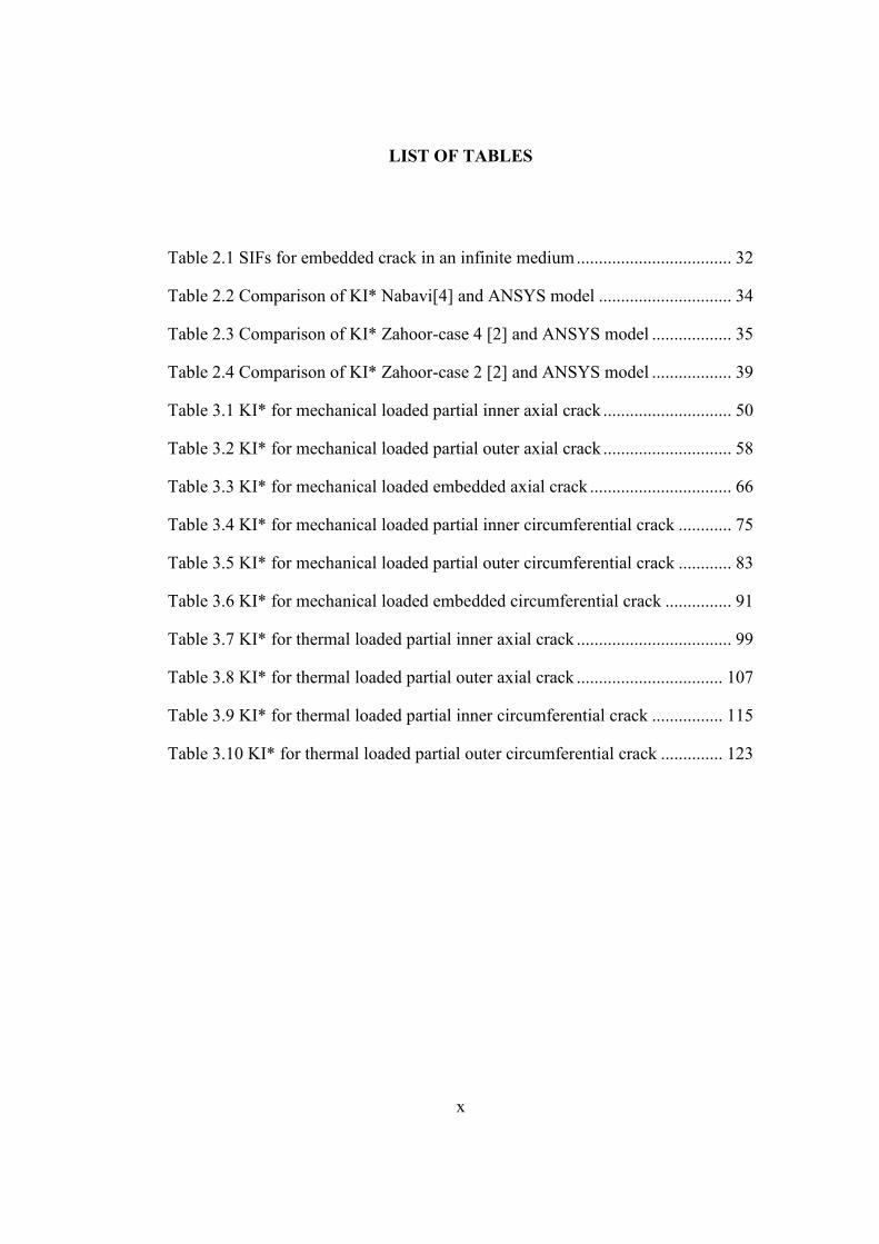
LIST OF TABLES
Table 2.1 SIFs for embedded crack in an infinite medium................................... 32
Table 2.2 Comparison of KI* Nabavi[4] and ANSYS model .............................. 34
Table 2.3 Comparison of KI* Zahoor-case 4 [2] and ANSYS model .................. 35
Table 2.4 Comparison of KI* Zahoor-case 2 [2] and ANSYS model .................. 39
Table 3.1 KI* for mechanical loaded partial inner axial crack ............................. 50
Table 3.2 KI* for mechanical loaded partial outer axial crack ............................. 58
Table 3.3 KI* for mechanical loaded embedded axial crack ................................ 66
Table 3.4 KI* for mechanical loaded partial inner circumferential crack ............ 75
Table 3.5 KI* for mechanical loaded partial outer circumferential crack ............ 83
Table 3.6 KI* for mechanical loaded embedded circumferential crack ............... 91
Table 3.7 KI* for thermal loaded partial inner axial crack ................................... 99
Table 3.8 KI* for thermal loaded partial outer axial crack ................................. 107
Table 3.9 KI* for thermal loaded partial inner circumferential crack ................ 115
Table 3.10 KI* for thermal loaded partial outer circumferential crack .............. 123

xi
LIST OF FIGURES
Figure 2.1 Basic modes of crack tip deformation ................................................... 6
Figure 2.2 Crack face, crack front [14] ................................................................... 7
Figure 2.3 Axial inner semi-elliptic crack............................................................... 7
Figure 2.4 Axial outer semi-elliptic crack............................................................... 8
Figure 2.5 Axial embedded elliptic crack ............................................................... 8
Figure 2.6 Circumferential inner semi-elliptic crack .............................................. 8
Figure 2.7 Circumferential outer semi-elliptic crack .............................................. 9
Figure 2.8 Circumferential embedded elliptic crack............................................... 9
Figure 2.9 SOLID95 geometry [14]...................................................................... 11
Figure 2.10 SOLID90 geometry [14].................................................................... 12
Figure 2.11 Keypoints on the crack front.............................................................. 12
Figure 2.12 Lines on the crack front ..................................................................... 13
Figure 2.13 Volumes around crack front .............................................................. 13
Figure 2.14 Cylindrical structure .......................................................................... 14
Figure 2.15 Volume around crack front and cylinder ........................................... 15
Figure 2.16 Crack and cylinder............................................................................. 15
Figure 2.17 Singular elements .............................................................................. 16
Figure 2.18 Quarter point of the singular elements............................................... 17
Figure 2.19 Singular elements around crack front [14] ........................................ 18
Figure 2.20 Meshing around crack front............................................................... 18
Figure 2.21 General view of the crack model ....................................................... 19
Figure 2.22 Symmetry areas around crack............................................................ 20

xii
Figure 2.23 Symmetry areas of the model ............................................................ 20
Figure 2.24 Axial inner semi-elliptic crack........................................................... 23
Figure 2.25 Axial outer semi-elliptic crack........................................................... 23
Figure 2.26 Axial embedded crack ....................................................................... 23
Figure 2.27 Partial circumferential cracks ............................................................ 24
Figure 2.28 Boundary conditions of thermal loading ........................................... 25
Figure 2.29 Results plot of thermal analysis......................................................... 26
Figure 2.30 Closer view of Figure 2.29 ................................................................ 26
Figure 2.31 Opened crack view after loading ....................................................... 27
Figure 2.32 Nodes used in DCT............................................................................ 28
Figure 2.33 Schematic view of nodes ................................................................... 29
Figure 2.34 Model of an elliptic crack in a huge cylinder .................................... 30
Figure 2.35 Closer view of the crack .................................................................... 31
Figure 2.36 Description of Φ angle....................................................................... 31
Figure 2.37 Comparison of results with closed formula ....................................... 32
Figure 2.38 Geometry used by Nabavi [4]............................................................ 33
Figure 2.39 Comparison of results with Nabavi [4].............................................. 34
Figure 2.40 Geometry used by Zahoor-case 4 [2]................................................. 35
Figure 2.41 Comparison of results for R/t=20 ...................................................... 36
Figure 2.42 Comparison of results for R/t=10 ...................................................... 37
Figure 2.43 Comparison of results for R/t=5 ........................................................ 37
Figure 2.44 Geometry used by Zahoor-case 2 [2]................................................. 38
Figure 2.45 Comparison of results for R/t=20 ...................................................... 40
Figure 2.46 Comparison of results for R/t=10 ...................................................... 40
Figure 2.47 Comparison of results for R/t=5 ........................................................ 41

xiii
Figure 3.1 Crack front angles for Type1 and Type7............................................. 43
Figure 3.2 KI* versus Φ, Type1, R/t=5, a/t=0.2 ................................................... 44
Figure 3.3 KI* versus Φ, Type1, R/t=5, a/t=0.4 ................................................... 44
Figure 3.4 KI* versus Φ, Type1, R/t=5, a/t=0.6 ................................................... 45
Figure 3.5 KI* versus Φ, Type1, R/t=10, a/t=0.2 ................................................. 45
Figure 3.6 KI* versus Φ, Type1, R/t=10, a/t=0.4 ................................................. 46
Figure 3.7 KI* versus Φ, Type1, R/t=10, a/t=0.6 ................................................. 46
Figure 3.8 KI* versus Φ, Type1, R/t=20, a/t=0.2 ................................................. 47
Figure 3.9 KI* versus Φ, Type1, R/t=20, a/t=0.4 ................................................. 47
Figure 3.10 KI* versus Φ, Type1, R/t=20, a/t=0.6 ............................................... 48
Figure 3.11 KI* at the deepest point versus a/t, Type1, R/t=5 ............................. 48
Figure 3.12 KI* at the deepest point versus a/t, Type1, R/t=10 ........................... 49
Figure 3.13 KI* at the deepest point versus a/t, Type1, R/t=20 ........................... 49
Figure 3.14 Crack front angles for Type2 and Type8........................................... 51
Figure 3.15 KI* versus Φ, Type2, R/t=5, a/t=0.2 ................................................. 52
Figure 3.16 KI* versus Φ, Type2, R/t=5, a/t=0.4 ................................................. 52
Figure 3.17 KI* versus Φ, Type2, R/t=5, a/t=0.6 ................................................. 53
Figure 3.18 KI* versus Φ, Type2, R/t=10, a/t=0.2 ............................................... 53
Figure 3.19 KI* versus Φ, Type2, R/t=10, a/t=0.4 ............................................... 54
Figure 3.20 KI* versus Φ, Type2, R/t=10, a/t=0.6 ............................................... 54
Figure 3.21 KI* versus Φ, Type2, R/t=20, a/t=0.2 ............................................... 55
Figure 3.22 KI* versus Φ, Type2, R/t=20, a/t=0.4 ............................................... 55
Figure 3.23 KI* versus Φ, Type2, R/t=20, a/t=0.6 ............................................... 56
Figure 3.24 KI* at the deepest point versus a/t, Type2, R/t=5 ............................. 56
Figure 3.25 KI* at the deepest point versus a/t, Type2, R/t=10 ........................... 57

xiv
Figure 3.26 KI* at the deepest point versus a/t, Type2, R/t=20 ........................... 57
Figure 3.27 Crack front angles for Type3............................................................. 59
Figure 3.28 KI* versus Φ, Type3, R/t=5, a/t=0.2 ................................................. 60
Figure 3.29 KI* versus Φ, Type3, R/t=5, a/t=0.3 ................................................. 60
Figure 3.30 KI* versus Φ, Type3, R/t=5, a/t=0.4 ................................................. 61
Figure 3.31 KI* versus Φ, Type3, R/t=10, a/t=0.2 ............................................... 61
Figure 3.32 KI* versus Φ, Type3, R/t=10, a/t=0.3 ............................................... 62
Figure 3.33 KI* versus Φ, Type3, R/t=10, a/t=0.4 ............................................... 62
Figure 3.34 KI* versus Φ, Type3, R/t=20, a/t=0.2 ............................................... 63
Figure 3.35 KI* versus Φ, Type3, R/t=20, a/t=0.3 ............................................... 63
Figure 3.36 KI* versus Φ, Type3, R/t=20, a/t=0.4 ............................................... 64
Figure 3.37 KI* at Φ=0 versus a/t, Type3, R/t=5 ................................................. 64
Figure 3.38 KI* at Φ=0 versus a/t, Type3, R/t=10 ............................................... 65
Figure 3.39 KI* at Φ=0 versus a/t, Type3, R/t=20 ............................................... 65
Figure 3.40 Crack front angles for Type4 and Type9........................................... 67
Figure 3.41 KI* versus Φ, Type4, R/t=5, a/t=0.2 ................................................. 68
Figure 3.42 KI* versus Φ, Type4, R/t=5, a/t=0.3 ................................................. 69
Figure 3.43 KI* versus Φ, Type4, R/t=5, a/t=0.4 ................................................. 69
Figure 3.44 KI* versus Φ, Type4, R/t=10, a/t=0.2 ............................................... 70
Figure 3.45 KI* versus Φ, Type4, R/t=10, a/t=0.3 ............................................... 70
Figure 3.46 KI* versus Φ, Type4, R/t=10, a/t=0.4 ............................................... 71
Figure 3.47 KI* versus Φ, Type4, R/t=20, a/t=0.2 ............................................... 71
Figure 3.48 KI* versus Φ, Type4, R/t=20, a/t=0.3 ............................................... 72
Figure 3.49 KI* versus Φ, Type4, R/t=20, a/t=0.4 ............................................... 72
Figure 3.50 KI* at the deepest point versus a/t, Type4, R/t=5 ............................. 73

xv
Figure 3.51 KI* at the deepest point versus a/t, Type4, R/t=10 ........................... 73
Figure 3.52 KI* at the deepest point versus a/t, Type4, R/t=20 ........................... 74
Figure 3.53 Crack front angles for Type5 and Type10......................................... 76
Figure 3.54 KI* versus Φ, Type5, R/t=5, a/t=0.2 ................................................. 77
Figure 3.55 KI* versus Φ, Type5, R/t=5, a/t=0.3 ................................................. 77
Figure 3.56 KI* versus Φ, Type5, R/t=5, a/t=0.4 ................................................. 78
Figure 3.57 KI* versus Φ, Type5, R/t=10, a/t=0.2 ............................................... 78
Figure 3.58 KI* versus Φ, Type5, R/t=10, a/t=0.3 ............................................... 79
Figure 3.59 KI* versus Φ, Type5, R/t=10, a/t=0.4 ............................................... 79
Figure 3.60 KI* versus Φ, Type5, R/t=20, a/t=0.2 ............................................... 80
Figure 3.61 KI* versus Φ, Type5, R/t=20, a/t=0.3 ............................................... 80
Figure 3.62 KI* versus Φ, Type5, R/t=20, a/t=0.4 ............................................... 81
Figure 3.63 KI* at the deepest point versus a/t, Type5, R/t=5 ............................. 81
Figure 3.64 KI* at the deepest point versus a/t, Type5, R/t=10 ........................... 82
Figure 3.65 KI* at the deepest point versus a/t, Type5, R/t=20 ........................... 82
Figure 3.66 Crack front angles for Type6............................................................. 84
Figure 3.67 KI* versus Φ, Type6, R/t=5, a/t=0.2 ................................................. 85
Figure 3.68 KI* versus Φ, Type6, R/t=5, a/t=0.3 ................................................. 85
Figure 3.69 KI* versus Φ, Type6, R/t=5, a/t=0.4 ................................................. 86
Figure 3.70 KI* versus Φ, Type6, R/t=10, a/t=0.2 ............................................... 86
Figure 3.71 KI* versus Φ, Type6, R/t=10, a/t=0.3 ............................................... 87
Figure 3.72 KI* versus Φ, Type6, R/t=10, a/t=0.4 ............................................... 87
Figure 3.73 KI* versus Φ, Type6, R/t=20, a/t=0.2 ............................................... 88
Figure 3.74 KI* versus Φ, Type6, R/t=20, a/t=0.3 ............................................... 88
Figure 3.75 KI* versus Φ, Type6, R/t=20, a/t=0.4 ............................................... 89

xvi
Figure 3.76 KI* at Φ=0 versus a/t, Type6, R/t=5 ................................................. 89
Figure 3.77 KI* at Φ=0 versus a/t, Type6, R/t=10 ............................................... 90
Figure 3.78 KI* at Φ=0 versus a/t, Type6, R/t=20 ............................................... 90
Figure 3.79 KI* versus Φ, Type7, R/t=5, a/t=0.2 ................................................. 92
Figure 3.80 KI* versus Φ, Type7, R/t=5, a/t=0.4 ................................................. 93
Figure 3.81 KI* versus Φ, Type7, R/t=5, a/t=0.6 ................................................. 93
Figure 3.82 KI* versus Φ, Type7, R/t=10, a/t=0.2 ............................................... 94
Figure 3.83 KI* versus Φ, Type7, R/t=10, a/t=0.4 ............................................... 94
Figure 3.84 KI* versus Φ, Type7, R/t=10, a/t=0.6 ............................................... 95
Figure 3.85 KI* versus Φ, Type7, R/t=20, a/t=0.2 ............................................... 95
Figure 3.86 KI* versus Φ, Type7, R/t=20, a/t=0.4 ............................................... 96
Figure 3.87 KI* versus Φ, Type7, R/t=20, a/t=0.6 ............................................... 96
Figure 3.88 KI* at the deepest point versus a/t, Type7, R/t=5 ............................. 97
Figure 3.89 KI* at the deepest point versus a/t, Type7, R/t=10 ........................... 97
Figure 3.90 KI* at the deepest point versus a/t, Type7, R/t=20 ........................... 98
Figure 3.91 KI* versus Φ, Type8, R/t=5, a/t=0.2 ............................................... 100
Figure 3.92 KI* versus Φ, Type8, R/t=5, a/t=0.4 ............................................... 101
Figure 3.93 KI* versus Φ, Type8, R/t=5, a/t=0.6 ............................................... 101
Figure 3.94 KI* versus Φ, Type8, R/t=10, a/t=0.2 ............................................. 102
Figure 3.95 KI* versus Φ, Type8, R/t=10, a/t=0.4 ............................................. 102
Figure 3.96 KI* versus Φ, Type8, R/t=10, a/t=0.6 ............................................. 103
Figure 3.97 KI* versus Φ, Type8, R/t=20, a/t=0.2 ............................................. 103
Figure 3.98 KI* versus Φ, Type8, R/t=20, a/t=0.4 ............................................. 104
Figure 3.99 KI* versus Φ, Type8, R/t=20, a/t=0.6 ............................................. 104
Figure 3.100 KI* at the deepest point versus a/t, Type8, R/t=5 ......................... 105

xvii
Figure 3.101 KI* at the deepest point versus a/t, Type8, R/t=10 ....................... 105
Figure 3.102 KI* at the deepest point versus a/t, Type8, R/t=20 ....................... 106
Figure 3.103 KI* versus Φ, Type9, R/t=5, a/t=0.2 ............................................. 108
Figure 3.104 KI* versus Φ, Type9, R/t=5, a/t=0.3 ............................................. 109
Figure 3.105 KI* versus Φ, Type9, R/t=5, a/t=0.4 ............................................. 109
Figure 3.106 KI* versus Φ, Type9, R/t=10, a/t=0.2 ........................................... 110
Figure 3.107 KI* versus Φ, Type9, R/t=10, a/t=0.3 ........................................... 110
Figure 3.108 KI* versus Φ, Type9, R/t=10, a/t=0.4 ........................................... 111
Figure 3.109 KI* versus Φ, Type9, R/t=20, a/t=0.2 ........................................... 111
Figure 3.110 KI* versus Φ, Type9, R/t=20, a/t=0.3 ........................................... 112
Figure 3.111 KI* versus Φ, Type9, R/t=20, a/t=0.4 ........................................... 112
Figure 3.112 KI* at the deepest point versus a/t, Type9, R/t=5 ......................... 113
Figure 3.113 KI* at the deepest point versus a/t, Type9, R/t=10 ....................... 113
Figure 3.114 KI* at the deepest point versus a/t, Type9, R/t=20 ....................... 114
Figure 3.115 KI* versus Φ, Type10, R/t=5, a/t=0.2 ........................................... 116
Figure 3.116 KI* versus Φ, Type10, R/t=5, a/t=0.3 ........................................... 117
Figure 3.117 KI* versus Φ, Type10, R/t=5, a/t=0.4 ........................................... 117
Figure 3.118 KI* versus Φ, Type10, R/t=10, a/t=0.2 ......................................... 118
Figure 3.119 KI* versus Φ, Type10, R/t=10, a/t=0.3 ......................................... 118
Figure 3.120 KI* versus Φ, Type10, R/t=10, a/t=0.4 ......................................... 119
Figure 3.121 KI* versus Φ, Type10, R/t=20, a/t=0.2 ......................................... 119
Figure 3.122 KI* versus Φ, Type10, R/t=20, a/t=0.3 ......................................... 120
Figure 3.123 KI* versus Φ, Type10, R/t=20, a/t=0.4 ......................................... 120
Figure 3.124 KI* at the deepest point versus a/t, Type10, R/t=5 ....................... 121
Figure 3.125 KI* at the deepest point versus a/t, Type10, R/t=10 ..................... 121

xviii
Figure 3.126 KI* at the deepest point versus a/t, Type10, R/t=20 ..................... 122
Figure 4.1 Propagation of a circumferential inner crack..................................... 124

xix
LIST OF SYMBOLS
a : Half crack length in minor axis direction in elliptical crack
c : Half crack length in major axis direction in elliptical crack
t : Wall thickness of the cylinder
Ri : Inner radius of the hollow cylinder
Ro : Outer radius of the hollow cylinder
R : Nominal radius of the hollow cylinder, 2
RoRi +
L : Length of the cylinder
KI : Mode I Stress Intensity Factor
KI* : Non Dimensional Stress Intensity Factor
E : Young’s Modulus
µ : Poisson’s Ratio
Pi : Internal Pressure
σ : Axial Load
Φ : Crack front angle
α : Thermal Expansion Coefficient

1
CHAPTER 1
1. INTRODUCTION
Cylindrical structures are widely used in the industry. (Missile casings, gas
and oil pipelines, pressure vessels, nuclear piping, etc.) These cylindrical
structures often have severe operating conditions, such as high internal pressure,
high or low operating temperatures and thermal shock. In case of pipelines also
some external forces, like earthquake and wind effect these structures. Both
operating conditions and external forces are important for the stress intensity
factor (SIF) for longitudinal and circumferential cracks in the piping.
Crack defects are serious in these applications. To obtain the safe design
conditions SIF calculations should be considered. According to have a safe
design, leak-before-break (LBB) analysis is very important. Wilkowsky[1]
describes this, as a methodology which ensures that a leak will be discovered prior
to a fracture occurring in service. If a pressure vessel has LBB behavior, a small
through-wall crack causes leakage of medium and brittle break accident will be
thus prevented.
In applications mechanical and thermal loads are applied together.
Application of pressure and thermal shock can cause a crack in the structure.
Fracture mechanics approach deals with the control of the fracture problem.
This is possible with the calculation of the stress intensity factor (SIF).
In this study, SIF calculations of cylindrical structures for different locations
of elliptic and semi-elliptic cracks are obtained using FEM.

2
1.1. Literature Survey
In the past there have been many studies to obtain SIF values for different
types of cracks in different types of structures. There are many types of cracks for
cylindrical structures; elliptic axial, fully axial, elliptic circumferential, fully
circumferential, etc. Such crack problems can be solved by two or three
dimensional FEM analysis. Whether 2D or 3D modelling is to be used depends on
the structure, the type of the crack and the loading.
Two earlier studies relevant to the problems under consideration are as
follows: In Zahoor’s study [2] a number of solutions for different types of cracks
in pipes are collected together. In case 1, circumferential through wall crack; in
case 2, finite length circumferential part-through crack; in case 3, full
circumference internal part-through crack; in case 4, finite length axial part-
through crack; and in case 5, long axial part-through crack are considered and
closed form SIF expressions were given. Closed formulas given for case 2 and
case 4 are used for model verification in this master thesis. In verification of
modeling part, the details of this comparison are given.
Raju and Newman [3] calculated stress intensity factors for internal and
external circumferential semi-elliptic surface cracks in cylindrical vessels under
mechanical loading.
Some of the more recent studies are briefly reviewed below. Especially
Shahani and Nabavi have many studies about cracks in cylinders.
In one of the studies by Shahani and Nabavi [4] stress intensity factors are
obtained for internal semi-elliptic, longitudinal cracks in a thick walled cylinder
under mechanical and thermal loading. Analytical and weight function method is
used for calculations. Results for the mechanically loaded internal longitudinal
crack are used for model verification in this master thesis. Details of this work can
be found in the following pages.
In another study of Shahani and Nabavi [5] transient thermal load is applied
to a pressurized thick-walled cylinder and problem is solved analytically.

3
Solutions are obtained for internal longitudinal semi-elliptical crack. Thermal and
mechanical boundary conditions are assumed to act on the inner and outer
surfaces of the cylinder. The stress intensity factors are extracted for the deepest
point and the surface points of the semi-elliptical crack using the weight function
method.
In yet another study of Shahani and Nabavi [6], stress intensity factors are
obtained for internal longitudinal semi-elliptical cracks in a finite length thick
walled cylinder. Internal pressure is applied as a mechanical load. Especially
cylinder length effect is observed in this work. The results show that the stress
intensity factor increases as the cylinder length decreases, especially at the corner
point of the crack compared with the deepest point.
In the study of Shahani and Habibi [7] stress intensity factors in a hollow
cylinder containing a circumferential semi-elliptical crack are obtained for multi-
axial loading; Axial force, bending moment and torsion. Three dimensional FEM
analyses are applied.
In Miura et al. [8], a comparison of stress intensity factor solutions is made
for cylinders with axial and circumferential cracks. In the study six cases of the
cracked cylinders are considered. In three cases, cracks are located inside of the
cylinder and in the other cases, cylinders are through-wall cracked.
Many studies are performed in METU on finite element modelling of crack
problems. Five of the master theses are briefly reviewed below:
One of the earlier studies about finite element analysis of fracture mechanics
problems is the study of Acar [9]. In this study, APDL codes are generated for
modeling 3-D problems in Ansys. Stress Intensity Factors are calculated for
different crack types in hollow and solid long cylinders. Cylinders considered are
composed of either homogeneous or two dissimilar materials. Cracks studied are
fully circumferential inner edge, fully circumferential outer edge, fully
circumferential embedded and fully circumferential inner crack through dissimilar
layers. Uniform axial and internal pressure is applied.

4
In another study by Atalay [10] fully longitudinal and fully circumferential
cracks are considered in cylindrical and conical structures. Fully longitudinal
cracks are modeled by 3-D finite element approach and fully circumferential
cracks are modeled by 2-D finite element approach.
In study by Đnan [11], three dimensional surface cracking problem in
Functionally Graded Material (FGM) coatings bonded to homogeneous substrates
is modeled by finite element analysis. The surface crack is assumed to have a
semi – circular crack front profile. Mechanical and transient thermal loading is
applied to the model. Structure is modeled as a plate with finite length.
In study by Sabuncuoğlu [12], crack growth analysis methods for
functionally graded materials under mode I cyclic loading by using finite element
technique is developed. Also the growth of an elliptical crack which is a common
case in engineering applications is analyzed. The crack is assumed to be located in
an infinite medium. Therefore a huge cube is modelled to simulate the infinite
medium. Tension load is applied to the structure.
In study by Köşker [13], a three dimensional inclined semi-elliptic surface
crack in a Functionally Graded Material coating bonded to a homogeneous
substrate with a bond coat is modeled and analyzed. Transient thermal loading is
applied to the model. The results obtained in this study are the peak values of
mixed mode stress intensity factors and energy release rates around the crack front
for various inclination angles of the semi-elliptic surface crack embedded in the
FGM coating of the composite structure subjected to transient thermal loading.
1.2. Scope of the Study
In the literature, stress intensity factor solutions are obtained by different
researchers for cylindrical structures. Some of them considered internal cracks and
the others outer cracks. Some of them considered axial cracks and the others
circumferential cracks.

5
In this study, different locations of elliptic and semi-elliptical cracks in a
cylinder are considered. Stress intensity factors of inner surface, outer surface and
embedded cracks are calculated for both axial and circumferential cracks. During
the calculations, material of the cylinder is assumed to be homogeneous isotropic.
Three dimensional Finite Element Analysis (FEM) is performed by using
ANSYS 11.0. To facilitate modeling for end-users, APDL codes are developed for
each crack case. By using these codes, an end-user can easily model a cracked
cylinder and obtain SIFs just by providing certain input values in the ANSYS
environment. After solving the problem by FEM, that is, obtaining the
displacement field around the crack front, SIFs are calculated by using
Displacement Correlation Technique (DCT).
A number of sample results and comparisons with the existing results in the
literature are provided.

6
CHAPTER 2
2. FORMULATION OF THE PROBLEM
2.1. Fracture Mechanics Basics
Fracture mechanics is the field of mechanics concerned with initiation and
propagation of cracks in materials and structures. In many cases, failure of
engineering structures through fracture can be fatal. For instance, growth of cracks
in pressure vessels due to crack propagation could cause a fatal explosion. While
designing mechanical structures, fracture mechanics analysis is needed to avoid
fracture failure.
Fracture mechanics can be divided into linear elastic fracture mechanics
(LEFM) and elasto-plastic fracture mechanics (EPFM). For cases where plastic
zone size at the crack tip is small compared to the crack length, LEFM approach
provides good results in predicting fracture.
There are three basic modes of crack tip deformations as shown in Figure
2.1; Mode I (Tension, Opening), Mode II (In-Plane Shear, Sliding), and Mode III
(Out-Of-Plane Shear, Tearing)
Mode I Mode II Mode III
Figure 2.1 Basic modes of crack tip deformation

7
In this thesis, Mode I type of loading for semi-elliptic cracks in cylinders is
considered. The geometry of cracks under consideration is discussed below.
In Figure 2.2 crack face (both 2-D and 3-D), crack tip (2-D), crack front (3-
D) can be seen.
2-D Model 3-D Model
Figure 2.2 Crack face, crack front [14]
2.2. Geometry of the Problem
Six cases of semi-elliptic or elliptic cracks are examined in this study.
Elliptic and semi-elliptic shapes are frequently used in the literature since good
approximations to actual crack shapes can be obtained by varying a/c ratios. First
three of them are axial cracks and others are circumferential cracks.
In the models, it is assumed that L>>2c to avoid free surface effects.
Figure 2.3 Axial inner semi-elliptic crack

8
Figure 2.4 Axial outer semi-elliptic crack
Figure 2.5 Axial embedded elliptic crack
Figure 2.6 Circumferential inner semi-elliptic crack

9
Figure 2.7 Circumferential outer semi-elliptic crack
Figure 2.8 Circumferential embedded elliptic crack
In this thesis cylinders with 205 ≤≤t
R are considered. Such cylinders are widely
used as pipes, hydraulic cylinders, structural elements, etc.
2.3. Three Dimensional Crack Modeling
Finite Element analysis program ANSYS 11.0 is used for modeling. There
are two ways to communicate with ANSYS program. One of them is using the
ANSYS menu system, called the Graphical User Interface (GUI) and the other

10
way is using ANSYS commands. For the second way, either command window or
APDL codes can be used. APDL codes are text documents which ANSYS
commands can be written in it. From GUI, by following the instructions
<File→Read input from>, APDL codes can be used. By the help of APDL codes,
model can be changed easily. In this thesis, ANSYS Parametric Design Language
(APDL) subroutines are used. Also there are some ways to interface with the GUI
while using APDL. One of them is the *ASK command. By using this command,
running APDL code stops to get an input from the user. In this study, *ASK
command is used to get the inputs; a, c, t and R. Therefore cylinder and crack can
be modeled according to different dimensions.
There are two types of modelling; top down and bottom up modelling.
Bottom up modelling: The points that define the vertices of the model are
called keypoints and are the "lowest-order" solid model entities. If, in building a
solid model, one first creates keypoints, and then use those keypoints to define the
"higher-order" solid model entities (that is, lines, areas, and volumes), one is said
to be building the model "from the bottom up." [14]
Top down modelling: The ANSYS program also gives user the ability to
assemble a model using geometric primitives, which are fully-defined lines, areas,
and volumes. As one creates a primitive, the program automatically creates all the
"lower" entities associated with it. If the modeling effort begins with the "higher"
primitive entities, one is said to be building the model "from the top down." [14]
These two methods can be combined as done in this thesis study. In this
study, modelling of the crack is bottom up style and modelling of the cylinder is
top down style.
MESH200, SOLID95 and SOLID 90 are used as element types for meshing.
MESH200; is a facet type meshing which means the element is subdivided
into smaller portions called facets. Facets are piecewise linear surface
approximations of the actual element face. MESH200 is a mesh-only element,
contributing nothing to the solution. This element is used for the successive steps
of meshing. More information can be found in [14].

11
SOLID95; is a 3-D, 20-Node structural solid element. It can tolerate
irregular shapes without as much loss of accuracy. SOLID95 elements have
compatible displacement shapes and are well suited to model curved boundaries.
The element is defined by 20 nodes having three degrees of freedom per node:
translations in the nodal x, y, and z directions. [14]. In this study prism option is
used around the crack front as singular elements. According to this, O, P, W and
A, B and K, L, S will be crack front nodes. X, V and T, R will be quarter nodes.
Normal configuration of the element will be used for rest of the model.
Figure 2.9 SOLID95 geometry [14]
SOLID90; is a 3-D, 20-Node thermal solid element. The element has 20
nodes with a single degree of freedom, temperature, at each node. The 20-node
elements have compatible temperature shapes and are well suited to model curved
boundaries. The 20-node thermal element is applicable to a 3-D, steady-state or
transient thermal analysis. If the model containing this element is also to be
analyzed structurally, the element should be replaced by the equivalent structural

12
element such as SOLID95. [14]. Prism option of SOLID90 will be used around
crack front in a similar way with SOLID95. For the rest of the model regular
option will be used.
Figure 2.10 SOLID90 geometry [14]
For axial inner semi-elliptic crack, ten keypoints are generated for
modelling half of the crack. Crack front is divided into eight equal parts by
keypoints 1-9. 9th keypoint is at 90° and 10th keypoint is at 100°. 10th keypoint
will be no more needed when cylinder is created and will be deleted.
Figure 2.11 Keypoints on the crack front

13
A semi-circular area is created at Keypoint 1 perpendicular to the plane on
which keypoints are created. This area is created to form the tubular volume
around crack front in the following steps.
Then, lines are created between these keypoints following an elliptical path.
Figure 2.12 Lines on the crack front
Area created at Keypoint 1 is dragged along the lines to form a tubular
volume around crack front.
Figure 2.13 Volumes around crack front
Cylinder is generated including the crack. Cylinder is divided into sub
volumes. These volumes will be meshed by different element sizes in the
following steps. The smallest volume around crack will be the finest mesh. The
volumes around this small volume will be less fine. Finally, rest of the cylinder

14
will have coarse mesh. Quarter of the cylinder is generated and symmetry
boundary conditions are used at the bottom and side areas.
Figure 2.14 Cylindrical structure
As can be seen in Figure 2.14 there is a part of tubular volume getting out
from the inner surface of the cylinder. After overlapping volumes the excess part
of this volume will be deleted. The tubular volume is created for 100°. If it is
created for 90°, then the volume can not reach the inner surface of the cylinder
and there will be a missing volume. To avoid this situation volume is dragged
along 100°, getting out of the cylinder. The situation is shown in Figure 2.15

15
Missing volume
Figure 2.15 Volume around crack front and cylinder
The excess volume is deleted and now the structure is ready to be meshed.
Figure 2.16 Crack and cylinder
Inner surface of cylinder
Outer surface of cylinder
Tubular volume

16
KSCON command is used to mesh the area at the bottom of the tubular
volume around crack front. KSCON, specifies a keypoint about which an area
mesh will be skewed. This command defines a concentration keypoint about
which an area mesh will be skewed. It is useful for modeling stress concentrations
and crack tips. During meshing, elements are initially generated circumferentially
about, and radially away, from the keypoint. Lines attached to the keypoint are
given appropriate divisions and spacing ratios. Only one concentration keypoint
per unmeshed area is allowed. The KSCON command does not support 3-D
modeling. Therefore area is meshed with this command and then volumes around
crack front are swept.
Figure 2.17 Singular elements

17
Singular elements around crack front can be seen in Figure 2.17. Radius of
the singular elements (first row) is taken as 0.001mm. It is usually taken as a/1000
in the other thesis studies. [12], [13]
In this thesis study, working with different dimensions with one APDL code
is important, so radius of singular elements is taken to be constant. Therefore after
meshing, number of elements in the tubular volume for different dimensions
remains constant. When calculating stress intensity factors, number of nodes at
the point where SIFs are calculated will be used. Keeping the number of elements
constant, makes it possible to calculate SIFs along the crack front with APDL
code.
For linear elastic problems, the displacements near the crack front vary
as r , where r is the distance from the crack tip. The stresses and strains are
singular at the crack tip, varying as r1 . To produce this singularity in stresses
and strains, the elements around the crack front should be quadratic, with the
midside nodes placed at the quarter points. Such elements are called singular
elements. [14]
Midside nodes of the elements at the first row are placed at the quarter
points. These quarter point nodes are used to calculate the stress intensity factors
in displacement correlation technique.
Figure 2.18 Quarter point of the singular elements

18
First row of elements around the crack front should be singular elements.
Notice that the element shown in Figure 2.19 is wedge-shaped, with the KLPO
face collapsed into the line KO. SOLID95 or SOLID 90 elements are used around
crack tip.
Figure 2.19 Singular elements around crack front [14]
Meshed area is swept along the crack front. Meshed tubular volume can be
seen in Figure 2.20
Figure 2.20 Meshing around crack front

19
After meshing the volume around the crack front, other volumes are meshed
with different element sizes as seen in Figure 2.21.
For different a/c, a/t and R/t values, geometry of the crack and cylinder
change. In some cases volumes need special effort for meshing. Different element
sizes are needed with these cases.
Figure 2.21 General view of the crack model
Model has two symmetry planes. Planes along longitudinal and
circumferential directions are symmetry planes as seen in pink color in Figure
2.22 and 2.23. There is a point to be careful while determining symmetry areas.
Crack face area should not be selected as a symmetry area. Other vise crack would
not open when the load is applied to the structure.

20
Figure 2.22 Symmetry areas around crack
Figure 2.23 Symmetry areas of the model
The last thing before solving the problem is applying the loads. If a
mechanical load is to be applied, compressive loads should be positive and tensile
loads should be negative. In this study internal pressure or axial tension load is

21
applied according to the geometry. Therefore while internal pressure is stated as a
positive amount, tensile load is stated as a negative amount.
Then the problem is solved. If it is a thermal problem, first thermal problem
is solved and then thermal results file is read and structural solution is applied.
When the problem is solved, SIFs are calculated using DCT. To achieve
this, formulas are written in an APDL code. After solving the problem, ANSYS
calculates displacement at each node. Using this displacement values in formulas,
SIFs are calculated. These formulas are given in Chapter 2.6.
Non dimensional SIFs are calculated as follows:
• Mechanical loading: ( )aKIKI ⋅= πσ **
Where σ: Internal pressure or tensile stress
• Thermal loading: ( )aTEKIKI ⋅∆= πα ****
Where ∆T: Temperature difference between inner and outer surfaces,
α: Thermal Expansion coefficient and E: Young’s modulus
Results are written to the results file at the end of this procedure.

22
Main steps of modeling the problem are hence listed below:
• Element types are determined.
• Keypoints along the crack front are created.
• Lines are created between these keypoints.
• Volumes around crack front are created along the lines. (as a tube)
• Cylinder is created.
• Volumes created are overlapped.
• Unneeded volumes are deleted.
• Mesh is generated.
• Symmetry planes are determined.
• Loads are applied.
• Problem is solved.
• Stress intensity factors are calculated using displacement correlation
method.
• Non dimensional stress intensity factors are calculated.
• Results are written to file.

23
2.4.Loading Types
2.4.1.Mechanical Loading
2.4.1.1.Internal Pressure
Internal pressure is applied to the inner, outer and embedded axial cracks.
Internal pressure is applied as 10 MPa in all three cases. Edges of the cylinder are
stress free. This type of loading is shown in Figures 2.24 through 2.26.
Figure 2.24 Axial inner semi-elliptic crack
Figure 2.25 Axial outer semi-elliptic crack
Figure 2.26 Axial embedded crack
Stress free
Stress free
Stress free
Stress free
Stress free
Stress free

24
2.4.1.2.Axial Loading (Tension)
Axial tension loading is applied to the inner, outer and embedded
circumferential cracks. Axial stress applied is 10 MPa in all three cases. Crack is
located in the symmetry plane. This type of loading is shown in Figure 2.27.
Figure 2.27 Partial circumferential cracks
2.4.2.Thermal Loading
Surface temperatures at the inner and outer wall surfaces are specified for
the conduction and subsequent thermoelasticity problem. As a result a
temperature profile develops across the wall thickness.
The general behaviour of a crack in the cylinder wall can be explained as
follows: First assume that the crack is closed when the temperature is uniform
across the walls. Upon specifying different temperatures on the inner and outer
wall surfaces the cooler surface will tend to contract or expand less compared to
the hotter surface. As a result cooler side will experience tension due to the

25
constraint applied by the hotter side and hotter side would experience
compression.
Then a surface crack which is completely within the tensile surface region
(cooler side) of the wall would tend to open. If the crack is deep enough, part of it
would be in the compressive stress zone, hence it would close. Such problems are
known as crack contact problems, but they are not addressed in this thesis. In this
thesis study, thermal loads are applied to semi-elliptic surface cracks only.
As stated before, in this thesis, steady-state thermal loading is applied to the
structure. Inside temperature is lower than the outer temperature for structures
with inside surface crack for both axial and circumferential cracks. Vice versa,
inside temperature is greater than the outer temperature for structures with
external surface crack for both axial and circumferential cracks. Thermal
boundary conditions are shown in Figure 2.28.
Figure 2.28 Boundary conditions of thermal loading
Bottom surface, Symmetry plane
Inner temperature, Ti
Outer temperature, To
Insulated area
Symmetry plane

26
In Figure 2.29 thermal analysis results of an axial inner semi-elliptical crack
is shown. In this problem dimensions are; a=0.5mm, c=1.25mm, t=2.5mm,
R=50mm and L=500mm. Temperature of -100°C is applied inner surface of the
cylinder while temperature of 100°C is applied at the outer surface.
Figure 2.29 Results plot of thermal analysis
Figure 2.30 Closer view of Figure 2.29

27
2.5.Displacement Correlation Technique
By solving the problem, displacements of nodes are calculated by ANSYS.
Then stress intensity factors are calculated by using displacement correlation
technique. This technique has been used earlier in [11], [12], and [13].
Displacements of three nodes are used for this calculation. First one is a point on
the crack front. Second and third nodes are the nodes next to the first one. They
are on the crack face. The line passes through these three nodes is perpendicular to
crack front.
Figure 2.31 Opened crack view after loading
Crack front line
Crack face area

28
Figure 2.32 Nodes used in DCT
Then SIF is obtained as follows:
( )2332
32/3
222/3
3
RRRR
uRuRX bb
−
−= (4)
( ) XE
K I ⋅−
×=
214
2
νπ
(5)
( ) ( )
−
−⋅
−
×=
2332
32/3
222/3
3214
2
RRRR
uRuREK bbI ν
π (6)
The expressions above are taken from [13]

29
Figure 2.33 Schematic view of nodes
To find the SIF along the crack front, a coordinate system is placed at a
crack tip node, for example Node 42. X axis should be along the crack face and y
axis should be perpendicular to the crack face area. Nodes 42, 84, and 466 should
be used to place the coordinate system. These nodes are shown in Figure 2.33.
The nodes to be used in SIF calculations are Nodes 42, 84 and 85. 2bu and 3bu is
calculated by using displacements of these three nodes.
2.6.Verification of Modeling
2.6.1.Embedded crack in an infinite medium
At first, stress intensity factors for an embedded crack in a homogeneous
infinite plate are calculated to verify the model. Closed form equations from [15]
are used as benchmark solution. SIF is given as follows:
x
y

30
)(1 Φ⋅
= fQ
aK
πσ (1)
65.1
464.11
+=c
aQ (2)
2/1
2
2
2 )(cos)(sin)(
Φ
+Φ=Φc
af (3)
In order to obtain the problem of a crack in an infinite medium, with the
current modelling approach, a huge cylinder with an embedded crack is modelled
as shown in Figure 2.34.
Figure 2.34 Model of an elliptic crack in a huge cylinder
Symmetry planes
Tensile load is applied

31
Figure 2.35 Closer view of the crack
Then, half of an elliptic crack is modeled in the huge cylinder to eliminate
free surface effects as seen in Figure 2.35. Symmetry planes are defined. 50073
elements and 160351 nodes are used for the model. SIFs are calculated from finite
element model using DCT.
Dimensions of the model:
a =0.5mm, minor radius of the crack
c =1.5mm, major radius of the crack
σ =10Mpa, tension load applied
Ri=4 mm, Inner diameter of the cylinder
Ro=44 mm, Outer diameter of the cylinder
L/2=25mm, Half length of the cylinder
Figure 2.36 Description of Φ angle
SIF values calculated from closed form equation and FEM model are
compared in Table 2.1.

32
Table 2.1 SIFs for embedded crack in an infinite medium
φ Closed formula, KI
mmMPa
FEM Analysis,KI
mmMPa
Error (%)
0,00 6,5000 6,4762 0,3662
11,25 6,9473 6,9227 0,3541
22,50 7,8916 7,8697 0,2775
33,75 8,8722 8,8270 0,5095
45,00 9,7211 9,6858 0,3631
56,25 10,3923 10,3250 0,6476
67,50 10,8740 10,8140 0,5518
78,75 11,1634 11,0950 0,6127
90,00 11,2599 11,1910 0,6119
101,25 11,1634 11,1020 0,5500
112,50 10,8740 10,8280 0,4230
123,75 10,3923 10,3420 0,4840
135,00 9,7211 9,6829 0,3930
146,25 8,8722 8,8385 0,3798
157,50 7,8916 7,8628 0,3649
168,75 6,9473 6,9229 0,3512
180,00 6,5000 6,4667 0,5123
Figure 2.37 Comparison of results with closed formula
60,00
65,00 70,00
75,00
80,00
85,00 90,00
95,00
100,00
105,00 110,00
115,00
0 11,3 22,5 33,8 45 56,3 67,5 78,8 90 101 113 124 135 146 158 169 180
a/t
KI
Closed formula ANSYS

33
2.6.2.Axially cracked cylinder, Nabavi [4]
As a second benchmark solution, SIFs for an axially cracked cylinder are
considered.
Figure 2.38 Geometry used by Nabavi [4]
In Nabavi’s study [4], SIFs are obtained for internal semi-elliptic,
longitudinal cracks in a thick walled cylinder. Analytical and weight function
method is used for calculations. 10Mpa internal pressure is applied in the
problem. Internal pressure is applied both on the inner surface of the cylinder and
the crack face. Results are given as a graph in Nabavi’s study [4].
SIF values calculated at the deepest points are compared for the following
geometries.

34
Table 2.2 Comparison of KI* Nabavi[4] and ANSYS model
a (mm) R/t a/c a/t KI*, NABAVI [4] KI*, ANSYS ERROR %
2 4.5 0.2 0.2 5.80 5.75 0.86
3 4.5 0.2 0.3 6.20 6.03 2.74
4 4.5 0.2 0.4 6.70 6.51 2.84
5 4.5 0.2 0.5 7.25 7.15 1.38
6 4.5 0.2 0.6 8.00 7.91 1.13
7 4.5 0.2 0.7 8.90 8.78 1.35
8 4.5 0.2 0.8 9.90 9.88 0.20
2 4.5 0.4 0.2 5.70 5.00 12.28
3 4.5 0.4 0.3 5.75 5.09 11.48
4 4.5 0.4 0.4 5.90 5.23 11.36
5 4.5 0.4 0.5 6.20 5.44 12.26
6 4.5 0.4 0.6 6.40 5.71 10.78
7 4.5 0.4 0.7 6.80 6.03 11.32
8 4.5 0.4 0.8 7.20 6.47 10.14
2 4.5 1.0 0.2 5.30 3.49 34.15
3 4.5 1.0 0.3 5.30 3.45 34.91
4 4.5 1.0 0.4 5.30 3.43 35.28
5 4.5 1.0 0.5 5.30 3.42 35.47
6 4.5 1.0 0.6 5.30 3.42 35.47
7 4.5 1.0 0.7 5.30 3.45 34.91
8 4.5 1.0 0.8 5.30 3.52 33.58
2,00
2,50
3,00
3,50
4,00
4,50
5,00
5,50
6,00
6,50
7,00
7,50
8,00
8,50
9,00
9,50
10,00
0,2 0,3 0,4 0,5 0,6 0,7 0,8
a/t
KI*
Nabavi,a/c=0.2
Nabavi,a/c=0.4
Nabavi,a/c=1
ANSYS,a/c=0.2
ANSYS,a/c=0.4
ANSYS,a/c=1
Figure 2.39 Comparison of results with Nabavi [4]
As it can be seen in the Figure 2.39, results follow similar paths. However
as a/c aproaches to 1, ANSYS analysis results get lower than Nabavi’s results.

35
2.6.3.Axially cracked cylinder, Zahoor-case 4 [2]
Figure 2.40 Geometry used by Zahoor-case 4 [2]
In Zahoor’s study [2] a number of solutions for different types of cracks in
pipes are collected together. At first longitudinal crack will be investigated.
10MPa internal pressure is applied in this case. R/t is considered as 5,10 and 20.
Table 2.3 Comparison of KI* Zahoor-case 4 [2] and ANSYS model
a (mm)
R/t a/l a/t KI*, Zahoor-case4 [2] KI*, ANSYS ERROR %
2 5 0.2 0.2 6.80 6.41 5.68
2 5 0.4 0.2 5.85 5.57 4.78
2 5 0.8 0.2 4.62 4.34 6.06
4 5 0.2 0.4 7.82 7.25 7.30
4 5 0.4 0.4 6.21 5.84 5.89
4 5 0.8 0.4 4.74 4.32 8.89
6 5 0.2 0.6 9.17 8.82 3.84
6 5 0.4 0.6 6.64 6.36 4.16
6 5 0.8 0.6 4.88 4.39 10.01
1 10 0.2 0.2 12.64 11.91 5.09
1 10 0.4 0.2 10.89 10.40 4.52
1 10 0.8 0.2 8.60 8.07 6.18
2 10 0.2 0.4 14.46 13.88 4.04
2 10 0.4 0.4 11.54 11.12 3.68
2 10 0.8 0.4 8.83 8.20 7.13
3 10 0.2 0.6 16.81 16.73 0.46
3 10 0.4 0.6 12.32 12.14 1.43
3 10 0.8 0.6 9.08 8.37 7.84
1 20 0.2 0.2 23.77 22.89 3.69
1 20 0.4 0.2 20.49 20.02 2.31
1 20 0.8 0.2 16.18 15.47 4.39
1 20 0.2 0.4 27.04 25.87 2.01
1 20 0.4 0.4 21.70 21.68 0.10
1 20 0.8 0.4 16.61 15.82 4.77
2 20 0.2 0.6 31.16 32.37 -1.10
2 20 0.4 0.6 23.10 23.58 -2.07
2 20 0.8 0.6 17.08 16.26 4.82

36
In this case, similar to the Nabavi’s study [4], internal pressure is applied
both on the inner surface of the cylinder and the crack face. Difference of this
study from Nabavi’s is the length parameters of the cylinder and the crack.
Nabavi’s study is applicable only for R/t is 4.5. The study of Zahoor is valid for
R/t is 5, 10 and 20. In Zahoor’s study it is remarked that the closed form
expression gives better than 4 percent accuracy but when 2a/l=12 and a/t<0.4, this
expression gives results that are overestimated by as much as 8 percent.
R/t=20
13,00
15,00
17,00
19,00
21,00
23,00
25,00
27,00
29,00
31,00
33,00
0,2 0,4 0,6
a/t
KI
Zahoor, a/c=0.2
Zahoor, a/c=0.4
Zahoor, a/c=0.8
ANSYS,a/c=0.2
ANSYS,a/c=0.4
ANSYS,a/c=0.8
Figure 2.41 Comparison of results for R/t=20

37
R/t=10
6,00
7,00
8,00
9,00
10,00
11,00
12,00
13,00
14,00
15,00
16,00
17,00
0,2 0,4 0,6
a/t
KI
Zahoor, a/c=0.2
Zahoor, a/c=0.4
Zahoor, a/c=0.8
ANSYS,a/c=0.2
ANSYS,a/c=0.4
ANSYS,a/c=0.8
Figure 2.42 Comparison of results for R/t=10
R/t=5
2,00
3,00
4,00
5,00
6,00
7,00
8,00
9,00
0,2 0,4 0,6
a/t
KI
Zahoor, a/c=0.2
Zahoor, a/c=0.4
Zahoor, a/c=0.8
ANSYS,a/c=0.2
ANSYS,a/c=0.4
ANSYS,a/c=0.8
Figure 2.43 Comparison of results for R/t=5
When R/t=20, results of Zahoor’s study and ANSYS model are closer but as
R/t decreases, results get different. For all R/t values graphics follow parallel
lines. As a result, when crack aspect ratio (a/c) is not close to 1, the difference
between results from ANSYS model and literature is acceptable. Therefore in the
sample cases the maximum value for a/c is taken as 0.8.

38
2.6.4.Circumferentially cracked cylinder, Zahoor-case 2 [2]
Figure 2.44 Geometry used by Zahoor-case 2 [2]
In Zahoor’s study [2], circumferential semi-elliptic crack is considered as
case 2. In this case, 10MPa tensile load is applied to the cylinder. R/t is considered
as 5,10 and 20.
SIF values for semi-elliptic circumferential crack at the inner surface of the
cylinder are compared for ANSYS and Zahoor’s results[2].

39
Table 2.4 Comparison of KI* Zahoor-case 2 [2] and ANSYS model
a (mm)
R/t a/c a/t KI*, Zahoor-case2 [2] KI*, ANSYS ERROR %
2 5 0.2 0.2 1.03 1.13 -10.28
2 5 0.4 0.2 0.92 0.97 -4.81
2 5 0.8 0.2 0.78 0.75 4.25
4 5 0.2 0.4 1.14 1.22 -6.96
4 5 0.4 0.4 0.97 1.00 -3.71
4 5 0.8 0.4 0.81 0.76 6.41
6 5 0.2 0.6 1.30 1.33 -1.99
6 5 0.4 0.6 1.03 1.05 -1.68
6 5 0.8 0.6 0.85 0.77 9.20
1 10 0.2 0.2 1.06 1.12 -5.74
1 10 0.4 0.2 0.95 0.98 -2.37
1 10 0.8 0.2 0.82 0.75 8.69
2 10 0.2 0.4 1.18 1.21 -2.32
2 10 0.4 0.4 1.01 1.00 0.64
2 10 0.8 0.4 0.86 0.75 12.42
3 10 0.2 0.6 1.37 1.34 2.07
3 10 0.4 0.6 1.08 1.05 2.68
3 10 0.8 0.6 0.91 0.77 15.08
1 20 0.2 0.2 1.09 1.11 -1.96
1 20 0.4 0.2 0.99 0.96 2.18
1 20 0.8 0.2 0.87 0.74 14.68
1 20 0.2 0.4 1.24 1.21 2.48
1 20 0.4 0.4 1.05 1.00 5.00
1 20 0.8 0.4 0.92 0.76 18.11
2 20 0.2 0.6 1.44 1.33 8.06
2 20 0.4 0.6 1.14 1.06 7.22
2 20 0.8 0.6 0.98 0.77 21.75

40
R/t=20
0,60
0,70
0,80
0,90
1,00
1,10
1,20
1,30
1,40
1,50
0,2 0,4 0,6
a/t
KI
Zahoor, a/c=0.2
Zahoor, a/c=0.4
Zahoor, a/c=0.8
ANSYS,a/c=0.2
ANSYS,a/c=0.4
ANSYS,a/c=0.8
Figure 2.45 Comparison of results for R/t=20
R/t=10
0,60
0,70
0,80
0,90
1,00
1,10
1,20
1,30
1,40
0,2 0,4 0,6
a/t
KI
Zahoor, a/c=0.2
Zahoor, a/c=0.4
Zahoor, a/c=0.8
ANSYS,a/c=0.2
ANSYS,a/c=0.4
ANSYS,a/c=0.8
Figure 2.46 Comparison of results for R/t=10

41
R/t=5
0,60
0,70
0,80
0,90
1,00
1,10
1,20
1,30
1,40
0,2 0,4 0,6
a/t
KI
Zahoor, a/c=0.2
Zahoor, a/c=0.4
Zahoor, a/c=0.8
ANSYS,a/c=0.2
ANSYS,a/c=0.4
ANSYS,a/c=0.8
Figure 2.47 Comparison of results for R/t=5
As R/t increases, the difference between the results of Zahoor[2] and
ANSYS model increases for a/c=0.8. Similar to the axial inner crack case (case 4),
as crack aspect ratio (a/c) increases, difference between the results increases. It is
noticed that when a/c=0.8 and R/t=20, the error is as much as 15-20 percent. As
R/t and a/c decreases, also error decreases.

42
CHAPTER 3
3. NUMERICAL RESULTS
Ten types of analysis are performed in this study.
TYPE1: Partial Inner Axial Semi-elliptic crack, inner pressure is applied
TYPE2: Partial Outer Axial Semi-elliptic crack, inner pressure is applied
TYPE3: Embedded Axial Elliptic crack, inner pressure is applied
TYPE4: Partial Inner Circumferential Semi-elliptic crack, tensile load is applied
TYPE5: Partial Outer Circumferential Semi-elliptic crack, tensile load is applied
TYPE6: Embedded Circumferential Elliptic crack, tensile load is applied
TYPE7: Partial Inner Axial Semi-elliptic crack, thermal load is applied
TYPE8: Partial Outer Axial Semi-elliptic crack, thermal load is applied
TYPE9: Partial Inner Circumferential Semi-elliptic crack, thermal load is applied
TYPE10: Partial Outer Circumferential Semi-elliptic crack, thermal load is
applied
Material is assumed to be a homogeneous isotropic material. Stainless steel
is considered in this analysis. Material properties are:
Young’s modulus: 200 GPa
Poissons ratio: 0.3
Coefficient of thermal expansion: 1.2 E-5 1/K
Thermal Conductivity: 25 W/m.K
Mass Density: 7600 kg/m3
Specific Heat: 460 J/kg.K

43
3.1.MECHANICAL LOADING
3.1.1.Inner Pressurized Partial Inner Axial Semi-elliptic Crack
Crack front angle 0 is the deepest point and angle 90 is the surface point.
Inner pressure of magnitude 10Mpa is applied to the structure. Results are
obtained for different R/t, a/t and a/c values. R is 50mm for all cases but a, c and t
change. Results are obtained for the following values;
R/t = 5, 10 and 20
a/t = 0.2, 0.4 and 0.6
a/c = 0.2, 0.4 and 0.8
Figure 3.1 Crack front angles for Type1 and Type7
Inner surface of the cylinder
Symmetry surface
Φ

44
Axial Inner Semi-elliptic Crack
R/t=5, a/t=0.2
3.00
3.50
4.00
4.50
5.00
5.50
6.00
6.50
7.00
0 11.25 22.5 33.75 45 56.25 67.5 78.75 90
Φ
KI*
a/c=0.2
a/c=0.4
a/c=0.8
Figure 3.2 KI* versus Φ, Type1, R/t=5, a/t=0.2
Axial Inner Semi-elliptic Crack
R/t=5, a/t=0.4
3.00
3.50
4.00
4.50
5.00
5.50
6.00
6.50
7.00
7.50
0 11.25 22.5 33.75 45 56.25 67.5 78.75 90
Φ
KI*
a/c=0.2
a/c=0.4
a/c=0.8
Figure 3.3 KI* versus Φ, Type1, R/t=5, a/t=0.4
45
Axial Inner Semi-elliptic Crack
R/t=5, a/t=0.6
3.50
4.00
4.50
5.00
5.50
6.00
6.50
7.00
7.50
8.00
8.50
9.00
9.50
0 11.25 22.5 33.75 45 56.25 67.5 78.75 90
Φ
KI*
a/c=0.2
a/c=0.4
a/c=0.8
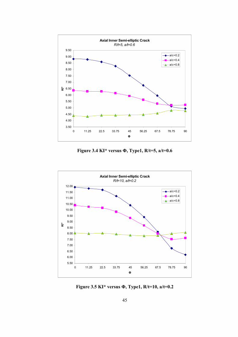
Figure 3.4 KI* versus Φ, Type1, R/t=5, a/t=0.6
Axial Inner Semi-elliptic Crack
R/t=10, a/t=0.2
5.50
6.00
6.50
7.00
7.50
8.00
8.50
9.00
9.50
10.00
10.50
11.00
11.50
12.00
0 11.25 22.5 33.75 45 56.25 67.5 78.75 90
Φ
KI*
a/c=0.2
a/c=0.4
a/c=0.8
Figure 3.5 KI* versus Φ, Type1, R/t=10, a/t=0.2

46
Axial Inner Semi-elliptic Crack
R/t=10, a/t=0.4
6.50
7.00
7.50
8.00
8.50
9.00
9.50
10.00
10.50
11.00
11.50
12.00
12.50
13.00
13.50
14.00
0 11.25 22.5 33.75 45 56.25 67.5 78.75 90
Φ
KI*
a/c=0.2
a/c=0.4
a/c=0.8
Figure 3.6 KI* versus Φ, Type1, R/t=10, a/t=0.4
Axial Inner Semi-elliptic Crack
R/t=10, a/t=0.6
7.00
8.00
9.00
10.00
11.00
12.00
13.00
14.00
15.00
16.00
17.00
0 11.25 22.5 33.75 45 56.25 67.5 78.75 90
Φ
KI*
a/c=0.2
a/c=0.4
a/c=0.8
Figure 3.7 KI* versus Φ, Type1, R/t=10, a/t=0.6

47
Axial Inner Semi-elliptic Crack
R/t=20, a/t=0.2
11.00
12.00
13.00
14.00
15.00
16.00
17.00
18.00
19.00
20.00
21.00
22.00
23.00
24.00
0 11.25 22.5 33.75 45 56.25 67.5 78.75 90
Φ
KI*
a/c=0.2
a/c=0.4
a/c=0.8
Figure 3.8 KI* versus Φ, Type1, R/t=20, a/t=0.2
Axial Inner Semi-elliptic Crack
R/t=20, a/t=0.4
13.00
14.00
15.00
16.00
17.00
18.00
19.00
20.00
21.00
22.00
23.00
24.00
25.00
26.00
27.00
28.00
0 11.25 22.5 33.75 45 56.25 67.5 78.75 90
Φ
KI*
a/c=0.2
a/c=0.4
a/c=0.8
Figure 3.9 KI* versus Φ, Type1, R/t=20, a/t=0.4

48
Axial Inner Semi-elliptic Crack
R/t=20, a/t=0.6
15.00
17.00
19.00
21.00
23.00
25.00
27.00
29.00
31.00
33.00
0 11.25 22.5 33.75 45 56.25 67.5 78.75 90
Φ
KI*
a/c=0.2
a/c=0.4
a/c=0.8
Figure 3.10 KI* versus Φ, Type1, R/t=20, a/t=0.6
Axial Inner Semi-elliptic Crack
R/t=5, Φ=0
3.00
3.50
4.00
4.50
5.00
5.50
6.00
6.50
7.00
7.50
8.00
8.50
9.00
9.50
0.2 0.4 0.6
a/t
KI*
a/c=0.2
a/c=0.4
a/c=0.8
Figure 3.11 KI* at the deepest point versus a/t, Type1, R/t=5

49
Axial Inner Semi-elliptic Crack
R/t=10, Φ=0
7.00
8.00
9.00
10.00
11.00
12.00
13.00
14.00
15.00
16.00
17.00
18.00
0.2 0.4 0.6
a/t
KI*
a/c=0.2
a/c=0.4
a/c=0.8
Figure 3.12 KI* at the deepest point versus a/t, Type1, R/t=10
Axial Inner Semi-elliptic Crack
R/t=20, Φ=0
14.00
16.00
18.00
20.00
22.00
24.00
26.00
28.00
30.00
32.00
34.00
0.2 0.4 0.6
a/t
KI*
a/c=0.2
a/c=0.4
a/c=0.8
Figure 3.13 KI* at the deepest point versus a/t, Type1, R/t=20

50
Table 3.1 KI* for mechanical loaded partial inner axial crack
R/t a/t a/c a
(mm) Φ=0 11.25 22.5 33.75 45 56.25 67.5 78.75 90
0.2 2 6.41 6.30 6.25 5.99 5.59 5.07 4.41 3.67 3.44
0.4 2 5.58 5.50 5.49 5.30 5.03 4.70 4.35 4.10 4.11 0.2
0.8 2 4.34 4.30 4.35 4.31 4.27 4.24 4.25 4.36 4.31
0.2 4 7.25 7.16 7.11 6.79 6.32 5.73 5.02 4.24 3.96
0.4 4 5.84 5.76 5.76 5.58 5.34 5.03 4.71 4.50 4.45 0.4
0.8 4 4.33 4.28 4.35 4.33 4.31 4.31 4.35 4.51 4.42
0.2 6 8.82 8.78 8.59 8.26 7.53 6.77 5.95 5.12 4.95
0.4 6 6.37 6.28 6.29 6.15 5.93 5.63 5.34 5.20 5.23
5
0.6
0.8 6 4.39 4.34 4.42 4.43 4.44 4.48 4.58 4.81 4.77
0.2 1 11.92 11.80 11.70 11.16 10.40 9.40 8.15 6.76 6.21
0.4 1 10.40 10.27 10.18 9.85 9.33 8.69 8.01 7.53 7.64 0.2
0.8 1 8.07 8.00 8.05 7.97 7.87 7.81 7.83 8.01 8.10
0.2 2 13.89 13.61 13.46 12.80 11.90 10.75 9.36 7.79 7.38
0.4 2 11.12 10.96 10.96 10.59 10.09 9.46 8.80 8.36 8.45 0.4
0.8 2 8.20 8.14 8.23 8.18 8.11 8.09 8.15 8.40 8.37
0.2 3 16.73 16.50 16.29 15.57 14.48 13.12 11.48 9.74 9.27
0.4 3 12.14 12.00 12.01 11.71 11.25 10.69 10.09 9.74 9.85
10
0.6
0.8 3 8.37 8.30 8.45 8.45 8.45 8.52 8.68 9.07 9.05
0.2 0.5 22.90 22.71 22.46 21.41 19.89 17.92 15.48 12.88 11.72
0.4 0.5 20.02 19.85 19.72 18.99 17.98 16.74 15.43 14.46 14.34 0.2
0.8 0.5 15.47 15.51 15.45 15.28 15.09 14.96 14.97 15.30 15.62
0.2 1 26.87 26.59 26.28 24.96 23.14 20.83 18.06 15.04 13.94
0.4 1 21.68 21.38 21.28 20.56 19.52 18.27 16.96 16.05 16.44 0.4
0.8 1 15.82 15.73 15.86 15.77 15.64 15.58 15.67 16.09 16.29
0.2 1.5 32.37 32.05 31.82 30.34 28.23 25.52 22.27 18.77 17.58
0.4 1.5 23.58 23.45 23.51 22.90 22.00 20.86 19.64 18.88 18.82
20
0.6
0.8 1.5 16.26 16.23 16.46 16.44 16.44 16.52 16.79 17.49 17.88
KI* at the deepest point is greater than KI* at the surface point for the cases
a/c is equal to 0.2 and 0.4. For the cases a/c is equal to 0.8, KI* values along the
crack front are almost constant. Also KI* values increases as R/t increases.
When a/c is equal to 0.2 and 0.4, KI* values increases as a/t increases.
Nevertheless, when a/c is equal to 0.8, KI* does not change so much as a/t
increases. So a/t does not affect KI* when a/c is 0.8.

51
3.1.2.Inner Pressurized Partial Outer Axial Semi-elliptic Crack
Crack front angle 0 is the deepest point and angle 90 is the surface point.
Inner pressure of magnitude 10Mpa is applied to the structure. Results are
obtained for different R/t, a/t and a/c values. R is 50mm for all cases but a, c and t
change. Results are obtained for the following ranges;
R/t = 5, 10 and 20
a/t = 0.2, 0.4 and 0.6
a/c = 0.2, 0.4 and 0.8
Figure 3.14 Crack front angles for Type2 and Type8
Outer surface of the cylinder
Symmetry surface
Φ

52
Axial Outer Semi-elliptic Crack
R/t=5, a/t=0.2
2.00
2.25
2.50
2.75
3.00
3.25
3.50
3.75
4.00
4.25
4.50
4.75
5.00
0 11.25 22.5 33.75 45 56.25 67.5 78.75 90
Φ
KI*
a/c=0.2
a/c=0.4
a/c=0.8
Figure 3.15 KI* versus Φ, Type2, R/t=5, a/t=0.2
Axial Outer Semi-elliptic Crack
R/t=5, a/t=0.4
2.50
2.75
3.00
3.25
3.50
3.75
4.00
4.25
4.50
4.75
5.00
5.25
5.50
5.75
6.00
6.25
0 11.25 22.5 33.75 45 56.25 67.5 78.75 90
Φ
KI*
a/c=0.2
a/c=0.4
a/c=0.8
Figure 3.16 KI* versus Φ, Type2, R/t=5, a/t=0.4

53
Axial Outer Semi-elliptic Crack
R/t=5, a/t=0.6
3.00
3.50
4.00
4.50
5.00
5.50
6.00
6.50
7.00
7.50
8.00
8.50
0 11.25 22.5 33.75 45 56.25 67.5 78.75 90
Φ
KI*
a/c=0.2
a/c=0.4
a/c=0.8
Figure 3.17 KI* versus Φ, Type2, R/t=5, a/t=0.6
Axial Outer Semi-elliptic Crack
R/t=10, a/t=0.2
5.00
5.50
6.00
6.50
7.00
7.50
8.00
8.50
9.00
9.50
10.00
10.50
0 11.25 22.5 33.75 45 56.25 67.5 78.75 90
Φ
KI*
a/c=0.2
a/c=0.4
a/c=0.8
Figure 3.18 KI* versus Φ, Type2, R/t=10, a/t=0.2

54
Axial Outer Semi-elliptic Crack
R/t=10, a/t=0.4
6.00
6.50
7.00
7.50
8.00
8.50
9.00
9.50
10.00
10.50
11.00
11.50
12.00
12.50
13.00
0 11.25 22.5 33.75 45 56.25 67.5 78.75 90
Φ
KI*
a/c=0.2
a/c=0.4
a/c=0.8
Figure 3.19 KI* versus Φ, Type2, R/t=10, a/t=0.4
Axial Outer Semi-elliptic Crack
R/t=10, a/t=0.6
7.00
8.00
9.00
10.00
11.00
12.00
13.00
14.00
15.00
16.00
17.00
18.00
0 11.25 22.5 33.75 45 56.25 67.5 78.75 90
Φ
KI*
a/c=0.2
a/c=0.4
a/c=0.8
Figure 3.20 KI* versus Φ, Type2, R/t=10, a/t=0.6

55
Axial Outer Semi-elliptic Crack
R/t=20, a/t=0.2
6.00
8.00
10.00
12.00
14.00
16.00
18.00
20.00
22.00
24.00
0 11.25 22.5 33.75 45 56.25 67.5 78.75 90
Φ
KI*
a/c=0.2
a/c=0.4
a/c=0.8
Figure 3.21 KI* versus Φ, Type2, R/t=20, a/t=0.2
Axial Outer Semi-elliptic Crack
R/t=20, a/t=0.4
12.00
13.00
14.00
15.00
16.00
17.00
18.00
19.00
20.00
21.00
22.00
23.00
24.00
25.00
26.00
27.00
0 11.25 22.5 33.75 45 56.25 67.5 78.75 90
Φ
KI*
a/c=0.2
a/c=0.4
a/c=0.8
Figure 3.22 KI* versus Φ, Type2, R/t=20, a/t=0.4

56
Axial Outer Semi-elliptic Crack
R/t=20, a/t=0.6
15.00
17.00
19.00
21.00
23.00
25.00
27.00
29.00
31.00
33.00
35.00
0 11.25 22.5 33.75 45 56.25 67.5 78.75 90
Φ
KI*
a/c=0.2
a/c=0.4
a/c=0.8
Figure 3.23 KI* versus Φ, Type2, R/t=20, a/t=0.6
Axial Outer Semi-elliptic Crack
R/t=5, Φ=0
3.00
3.50
4.00
4.50
5.00
5.50
6.00
6.50
7.00
7.50
8.00
8.50
0.2 0.4 0.6
a/t
KI*
a/c=0.2
a/c=0.4
a/c=0.8
Figure 3.24 KI* at the deepest point versus a/t, Type2, R/t=5

57
Axial Outer Semi-elliptic Crack
R/t=10, Φ=0
6.00
7.00
8.00
9.00
10.00
11.00
12.00
13.00
14.00
15.00
16.00
17.00
18.00
0.2 0.4 0.6
a/t
KI*
a/c=0.2
a/c=0.4
a/c=0.8
Figure 3.25 KI* at the deepest point versus a/t, Type2, R/t=10
Axial Outer Semi-elliptic Crack
R/t=20, Φ=0
13.00
15.00
17.00
19.00
21.00
23.00
25.00
27.00
29.00
31.00
33.00
35.00
0.2 0.4 0.6
a/t
KI*
a/c=0.2
a/c=0.4
a/c=0.8
Figure 3.26 KI* at the deepest point versus a/t, Type2, R/t=20

58
Table 3.2 KI* for mechanical loaded partial outer axial crack
R/t a/t a/c a
(mm) Φ=0 11.25 22.5 33.75 45 56.25 67.5 78.75 90
0.2 2 4.76 4.67 4.61 4.37 4.03 3.61 3.09 2.53 2.35
0.4 2 4.12 4.06 4.03 3.87 3.64 3.37 3.09 2.88 2.86 0.2
0.8 2 3.16 3.13 3.15 3.11 3.07 3.03 3.02 3.00 3.03
0.2 4 6.01 5.93 5.80 5.40 4.89 4.30 3.65 2.98 2.71
0.4 4 4.78 4.69 4.65 4.46 4.19 3.88 3.56 3.34 3.21 0.4
0.8 4 3.43 3.38 3.42 3.38 3.33 3.29 3.29 3.37 3.23
0.2 6 8.18 8.05 7.82 7.19 6.38 5.52 4.59 3.72 3.38
0.4 6 5.74 5.63 5.58 5.42 5.10 4.72 4.34 4.10 3.98
5
0.6
0.8 6 3.75 3.71 3.76 3.73 3.69 3.67 3.70 3.83 3.68
0.2 1 10.32 10.20 10.08 9.58 8.87 7.96 6.84 5.63 5.15
0.4 1 9.02 8.84 8.76 8.43 7.95 7.37 6.77 6.33 6.38 0.2
0.8 1 6.94 6.86 6.88 6.78 6.69 6.63 6.62 6.76 6.79
0.2 2 12.88 12.69 12.39 11.64 10.66 9.49 8.09 6.65 6.21
0.4 2 10.16 10.01 9.94 9.56 9.03 8.39 7.73 7.27 7.26 0.4
0.8 2 7.34 7.25 7.32 7.25 7.16 7.11 7.11 7.09 7.19
0.2 3 17.07 16.65 16.47 15.40 13.93 12.21 10.37 8.55 7.94
0.4 3 11.85 11.70 11.66 11.29 10.74 10.07 9.36 8.91 8.86
10
0.6
0.8 3 7.83 7.76 7.87 7.83 7.79 7.60 7.69 8.20 8.07
0.2 0.5 21.36 21.17 20.86 19.82 18.29 16.18 12.83 10.55 7.96
0.4 0.5 18.64 18.45 18.29 17.58 16.61 15.44 14.19 13.27 13.14 0.2
0.8 0.5 14.34 14.35 14.26 14.07 13.84 13.70 13.72 14.00 14.24
0.2 1 26.25 25.90 25.51 24.07 22.14 19.76 16.98 14.02 12.93
0.4 1 20.91 20.53 20.39 19.64 18.56 17.29 15.97 15.04 15.31 0.4
0.8 1 15.11 14.96 15.03 14.90 14.75 14.66 14.72 15.11 15.32
0.2 1.5 34.11 33.36 32.85 31.07 28.51 25.33 21.67 17.98 17.29
0.4 1.5 23.88 23.43 23.43 22.78 21.72 20.48 19.12 18.30 18.75
20
0.6
0.8 1.5 15.94 15.77 15.97 15.92 15.88 15.89 16.13 16.76 17.01
Similar to the inner axial crack case, KI* at the deepest point is greater than
KI* at the surface point for the cases a/c is equal to 0.2 and 0.4. For the cases a/c
is equal to 0.8, KI* values along the crack front are almost constant. Also KI*
values increases as R/t increases.
When a/c is equal to 0.2 and 0.4, KI* values increases as a/t increases.
Nevertheless, when a/c is equal to 0.8, KI* does not change so much as a/t
increases. So a/t does not affect KI* when a/c is 0.8.

59
3.1.3.Inner Pressurized Embedded Axial Crack
Crack front angle 0 is closer to the outer surface of the cylinder. Inner
pressure of magnitude 10Mpa is applied to the structure. Results are obtained for
different R/t, a/t and a/c values. R is 50mm for all cases but a, c and t change.
Results are obtained for the following ranges;
R/t = 5, 10 and 20
a/t = 0.2, 0.3 and 0.4
a/c = 0.2, 0.4 and 0.8
Figure 3.27 Crack front angles for Type3
Outer surface of cylinder
Inner surface of cylinder
Symmetry surface
Φ

60
Axial Embedded Elliptic Crack
R/t=5, a/t=0.2
1.75
2.00
2.25
2.50
2.75
3.00
3.25
3.50
3.75
4.00
4.25
4.50
4.75
0 22.5 45 67.5 90 112.5 135 157.5 180
Φ
KI*
a/c=0.2
a/c=0.4
a/c=0.8
Figure 3.28 KI* versus Φ, Type3, R/t=5, a/t=0.2
Axial Embedded Elliptic Crack
R/t=5, a/t=0.3
1.75
2.00
2.25
2.50
2.75
3.00
3.25
3.50
3.75
4.00
4.25
4.50
4.75
5.00
5.25
5.50
0 22.5 45 67.5 90 112.5 135 157.5 180
Φ
KI*
a/c=0.2
a/c=0.4
a/c=0.8
Figure 3.29 KI* versus Φ, Type3, R/t=5, a/t=0.3

61
Axial Embedded Elliptic Crack
R/t=5, a/t=0.4
2.00
2.50
3.00
3.50
4.00
4.50
5.00
5.50
6.00
6.50
7.00
0 22.5 45 67.5 90 112.5 135 157.5 180
Φ
KI*
a/c=0.2
a/c=0.4
a/c=0.8
Figure 3.30 KI* versus Φ, Type3, R/t=5, a/t=0.4
Axial Embedded Elliptic Crack
R/t=10, a/t=0.2
4.00
4.50
5.00
5.50
6.00
6.50
7.00
7.50
8.00
8.50
9.00
9.50
10.00
0 22.5 45 67.5 90 112.5 135 157.5 180
Φ
KI*
a/c=0.2
a/c=0.4
a/c=0.8
Figure 3.31 KI* versus Φ, Type3, R/t=10, a/t=0.2

62
Axial Embedded Elliptic Crack
R/t=10, a/t=0.3
4.00
4.50
5.00
5.50
6.00
6.50
7.00
7.50
8.00
8.50
9.00
9.50
10.00
10.50
11.00
11.50
0 22.5 45 67.5 90 112.5 135 157.5 180
Φ
KI*
a/c=0.2
a/c=0.4
a/c=0.8
Figure 3.32 KI* versus Φ, Type3, R/t=10, a/t=0.3
Axial Embedded Elliptic Crack
R/t=10, a/t=0.4
4.00
5.00
6.00
7.00
8.00
9.00
10.00
11.00
12.00
13.00
14.00
15.00
0 22.5 45 67.5 90 112.5 135 157.5 180
Φ
KI*
a/c=0.2
a/c=0.4
a/c=0.8
Figure 3.33 KI* versus Φ, Type3, R/t=10, a/t=0.4

63
Axial Embedded Elliptic Crack
R/t=20, a/t=0.2
8.00
9.00
10.00
11.00
12.00
13.00
14.00
15.00
16.00
17.00
18.00
19.00
20.00
21.00
0 22.5 45 67.5 90 112.5 135 157.5 180
Φ
KI*
a/c=0.2
a/c=0.4
a/c=0.8
Figure 3.34 KI* versus Φ, Type3, R/t=20, a/t=0.2
Axial Embedded Elliptic Crack
R/t=20, a/t=0.3
8.00
9.00
10.00
11.00
12.00
13.00
14.00
15.00
16.00
17.00
18.00
19.00
20.00
21.00
22.00
23.00
0 22.5 45 67.5 90 112.5 135 157.5 180
Φ
KI*
a/c=0.2
a/c=0.4
a/c=0.8
Figure 3.35 KI* versus Φ, Type3, R/t=20, a/t=0.3

64
Axial Embedded Elliptic Crack
R/t=20, a/t=0.4
8.00
10.00
12.00
14.00
16.00
18.00
20.00
22.00
24.00
26.00
28.00
30.00
0 22.5 45 67.5 90 112.5 135 157.5 180
Φ
KI*
a/c=0.2
a/c=0.4
a/c=0.8
Figure 3.36 KI* versus Φ, Type3, R/t=20, a/t=0.4
Axial Embedded Elliptic Crack
R/t=5, Φ=0
3.00
3.50
4.00
4.50
5.00
5.50
6.00
6.50
7.00
0.2 0.3 0.4
a/t
KI*
a/c=0.2
a/c=0.4
a/c=0.8
Figure 3.37 KI* at Φ=0 versus a/t, Type3, R/t=5

65
Axial Embedded Elliptic Crack
R/t=10, Φ=0
6.50
7.00
7.50
8.00
8.50
9.00
9.50
10.00
10.50
11.00
11.50
12.00
12.50
13.00
13.50
14.00
14.50
0.2 0.3 0.4
a/t
KI*
a/c=0.2
a/c=0.4
a/c=0.8
Figure 3.38 KI* at Φ=0 versus a/t, Type3, R/t=10
Axial Embedded Elliptic Crack
R/t=20, Φ=0
13.00
15.00
17.00
19.00
21.00
23.00
25.00
27.00
29.00
0.2 0.3 0.4
a/t
KI*
a/c=0.2
a/c=0.4
a/c=0.8
Figure 3.39 KI* at Φ=0 versus a/t, Type3, R/t=20

66
Table 3.3 KI* for mechanical loaded embedded axial crack
R/t a/t a/c a
(mm) Φ=0 22.50 45 67.5 90 112.5 135 157.5 180
0.2 2 4.50 4.27 3.73 2.85 1.97 2.90 3.84 4.41 4.66
0.4 2 3.99 3.82 3.45 2.89 2.53 2.94 3.56 3.98 4.17 0.2
0.8 2 3.16 3.09 3.00 2.90 2.87 2.95 3.11 3.25 3.33
0.2 3 5.12 4.75 4.00 2.99 2.05 3.05 4.15 4.94 5.28
0.4 3 4.35 4.12 3.64 3.03 2.64 3.09 3.79 4.31 4.54 0.3
0.8 3 3.28 3.20 3.09 2.98 2.95 3.06 3.24 3.41 3.51
0.2 4 6.76 5.93 4.59 3.22 2.18 3.32 4.75 6.13 6.77
0.4 4 5.30 4.87 4.08 3.28 2.84 3.37 4.23 5.03 5.43
5
0.4
0.8 4 3.70 3.54 3.33 3.15 3.12 3.25 3.50 3.77 3.94
0.2 1 9.54 9.08 7.94 6.06 4.16 6.10 8.04 9.23 9.72
0.4 1 8.49 8.16 7.35 6.15 5.35 6.20 7.46 8.32 8.68 0.2
0.8 1 6.74 6.62 6.40 6.15 6.06 6.22 6.52 6.78 6.92
0.2 1.5 10.79 10.06 8.49 6.33 4.33 6.40 8.61 10.20 10.94
0.4 1.5 9.23 8.75 7.75 6.41 5.57 6.48 7.89 8.92 9.43 0.3
0.8 1.5 7.04 6.88 6.61 6.33 6.24 6.41 6.76 7.08 7.26
0.2 2 13.94 12.29 9.63 6.83 4.61 6.91 9.74 12.32 13.78
0.4 2 11.12 10.20 8.60 6.92 5.96 6.99 8.71 10.31 11.18
10
0.4
0.8 2 7.90 7.56 7.08 6.69 6.56 6.78 7.24 7.76 8.10
0.2 0.5 19.70 18.71 16.33 12.45 8.54 12.50 16.43 18.85 19.86
0.4 0.5 17.36 16.79 15.12 12.62 10.95 12.66 15.20 16.94 17.60 0.2
0.8 0.5 13.89 13.63 13.17 12.64 12.41 12.70 13.28 13.81 14.04
0.2 0.8 21.96 20.46 17.32 12.95 8.84 13.01 17.45 20.61 22.04
0.4 0.8 18.94 17.91 15.87 13.13 11.37 13.19 16.00 18.10 19.01 0.3
0.8 0.8 14.48 14.12 13.57 12.99 12.75 13.06 13.72 14.34 14.67
0.2 1 28.04 24.82 19.47 13.90 9.37 13.96 19.56 24.75 27.77
0.4 1 22.71 20.76 17.53 14.10 12.13 14.17 17.60 20.74 22.72
20
0.4
0.8 1 16.23 15.48 14.51 13.70 13.40 13.79 14.67 15.64 16.33
KI* at the angles 0 and 180 is greater than KI* at the angle 90. As a/c
increases, KI* values along the crack front change less. KI* at the angle 180 is
greater than KI* at the angle 0. Similar to inner and outer axial cracks case, KI*
values increases as R/t increases.
As a/t increases, KI* increases for the same a/c value. But as a/c inreases,
effect of a/t decreases.
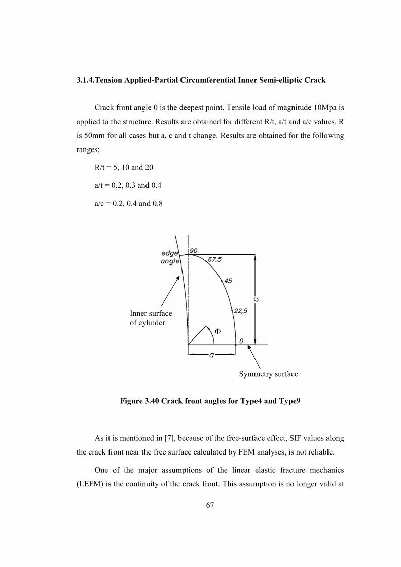
67
3.1.4.Tension Applied-Partial Circumferential Inner Semi-elliptic Crack
Crack front angle 0 is the deepest point. Tensile load of magnitude 10Mpa is
applied to the structure. Results are obtained for different R/t, a/t and a/c values. R
is 50mm for all cases but a, c and t change. Results are obtained for the following
ranges;
R/t = 5, 10 and 20
a/t = 0.2, 0.3 and 0.4
a/c = 0.2, 0.4 and 0.8
Figure 3.40 Crack front angles for Type4 and Type9
As it is mentioned in [7], because of the free-surface effect, SIF values along
the crack front near the free surface calculated by FEM analyses, is not reliable.
One of the major assumptions of the linear elastic fracture mechanics
(LEFM) is the continuity of the crack front. This assumption is no longer valid at
Inner surface of cylinder
Symmetry surface
Φ

68
corner points of the crack, where the crack front intersects the free surface of the
body. [7]
When analyzing 3D crack geometries, numerical values of fracture
parameters at corner points are not reliable, and the use of quarter-point finite
elements that model the square-root singularity of stresses and strains does not
produce accurate results near such points. Asymptotical approach should be used
at these points. [7]
Partial Circumferential Inner Semi-elliptic Crack
R/t=5, a/t=0.2
0.60
0.70
0.80
0.90
1.00
1.10
1.20
0 22.5 45 67.5 90
Φ
KI*
a/c=0.2
a/c=0.4
a/c=0.8
Figure 3.41 KI* versus Φ, Type4, R/t=5, a/t=0.2

69
Partial Circumferential Inner Semi-elliptic Crack
R/t=5, a/t=0.3
0.40
0.50
0.60
0.70
0.80
0.90
1.00
1.10
1.20
1.30
0 22.5 45 67.5 90
Φ
KI*
a/c=0.2
a/c=0.4
a/c=0.8
Figure 3.42 KI* versus Φ, Type4, R/t=5, a/t=0.3
Partial Circumferential Inner Semi-elliptic Crack
R/t=5, a/t=0.4
0.40
0.50
0.60
0.70
0.80
0.90
1.00
1.10
1.20
1.30
1.40
0 22.5 45 67.5 90
Φ
KI*
a/c=0.2
a/c=0.4
a/c=0.8
Figure 3.43 KI* versus Φ, Type4, R/t=5, a/t=0.4

70
Partial Circumferential Inner Semi-elliptic Crack
R/t=10, a/t=0.2
0.50
0.60
0.70
0.80
0.90
1.00
1.10
1.20
0 22.5 45 67.5 90
Φ
KI*
a/c=0.2
a/c=0.4
a/c=0.8
Figure 3.44 KI* versus Φ, Type4, R/t=10, a/t=0.2
Partial Circumferential Inner Semi-elliptic Crack
R/t=10, a/t=0.3
0.50
0.60
0.70
0.80
0.90
1.00
1.10
1.20
1.30
0 22.5 45 67.5 90
Φ
KI*
a/c=0.2
a/c=0.4
a/c=0.8
Figure 3.45 KI* versus Φ, Type4, R/t=10, a/t=0.3

71
Partial Circumferential Inner Semi-elliptic Crack
R/t=10, a/t=0.4
0.50
0.60
0.70
0.80
0.90
1.00
1.10
1.20
1.30
1.40
0 22.5 45 67.5 90
Φ
KI*
a/c=0.2
a/c=0.4
a/c=0.8
Figure 3.46 KI* versus Φ, Type4, R/t=10, a/t=0.4
Partial Circumferential Inner Semi-elliptic Crack
R/t=20, a/t=0.2
0.50
0.60
0.70
0.80
0.90
1.00
1.10
1.20
0 22.5 45 67.5 90
Φ
KI*
a/c=0.2
a/c=0.4
a/c=0.8
Figure 3.47 KI* versus Φ, Type4, R/t=20, a/t=0.2

72
Partial Circumferential Inner Semi-elliptic Crack
R/t=20, a/t=0.3
0.50
0.60
0.70
0.80
0.90
1.00
1.10
1.20
1.30
0 22.5 45 67.5 90
Φ
KI*
a/c=0.2
a/c=0.4
a/c=0.8
Figure 3.48 KI* versus Φ, Type4, R/t=20, a/t=0.3
Partial Circumferential Inner Semi-elliptic Crack
R/t=20, a/t=0.4
0.50
0.60
0.70
0.80
0.90
1.00
1.10
1.20
1.30
1.40
0 22.5 45 67.5 90
Φ
KI*
a/c=0.2
a/c=0.4
a/c=0.8
Figure 3.49 KI* versus Φ, Type4, R/t=20, a/t=0.4

73
Partial Circumferential Inner Semi-elliptic Crack
R/t=5, Φ=0
0.70
0.80
0.90
1.00
1.10
1.20
1.30
1.40
0.2 0.3 0.4
a/t
KI*
a/c=0.2
a/c=0.4
a/c=0.8
Figure 3.50 KI* at the deepest point versus a/t, Type4, R/t=5
Partial Circumferential Inner Semi-elliptic Crack
R/t=10, Φ=0
0.70
0.80
0.90
1.00
1.10
1.20
1.30
1.40
0.2 0.3 0.4
a/t
KI*
a/c=0.2
a/c=0.4
a/c=0.8
Figure 3.51 KI* at the deepest point versus a/t, Type4, R/t=10

74
Partial Circumferential Inner Semi-elliptic Crack
R/t=10, Φ=0
0.70
0.80
0.90
1.00
1.10
1.20
1.30
1.40
0.2 0.3 0.4
a/t
KI*
a/c=0.2
a/c=0.4
a/c=0.8
Figure 3.52 KI* at the deepest point versus a/t, Type4, R/t=20

75
Table 3.4 KI* for mechanical loaded partial inner circumferential crack
R/t a/t a/c a
(mm) Φ=0 22.50 45 67.5 90
0.2 2 1.13 1.12 1.02 0.79 0.67
0.4 2 0.97 0.95 0.87 0.74 0.72 0.2
0.8 2 0.75 0.75 0.73 0.72 0.77
0.2 3 1.22 1.21 1.07 0.77 0.51
0.4 3 1.00 0.98 0.90 0.77 0.73 0.3
0.8 3 0.76 0.76 0.74 0.73 0.78
0.2 4 1.33 1.30 1.10 0.77 0.50
0.4 4 1.05 1.03 0.93 0.80 0.75
5
0.4
0.8 4 0.77 0.77 0.75 0.74 0.79
0.2 1 1.12 1.11 1.00 0.80 0.57
0.4 1 0.98 0.95 0.86 0.74 0.73 0.2
0.8 1 0.75 0.74 0.72 0.72 0.76
0.2 1.5 1.21 1.20 1.08 0.85 0.58
0.4 1.5 1.00 0.98 0.90 0.77 0.76 0.3
0.8 1.5 0.75 0.76 0.74 0.73 0.79
0.2 2 1.34 1.31 1.17 0.87 0.59
0.4 2 1.05 1.03 0.94 0.81 0.79
10
0.4
0.8 2 0.77 0.77 0.75 0.75 0.82
0.2 0.5 1.11 1.10 0.98 0.78 0.58
0.4 0.5 0.96 0.94 0.86 0.73 0.74 0.2
0.8 0.5 0.74 0.74 0.72 0.71 0.76
0.2 0.8 1.21 1.18 1.06 0.84 0.64
0.4 0.8 1.00 0.98 0.89 0.77 0.77 0.3
0.8 0.8 0.76 0.76 0.74 0.74 0.79
0.2 1 1.33 1.30 1.16 0.91 0.64
0.4 1 1.06 1.04 0.95 0.82 0.83
20
0.4
0.8 1 0.77 0.77 0.76 0.76 0.81
KI* at the deepest point is greater than KI* at the surface point for the cases
a/c is equal to 0.2 and 0.4. For the cases a/c is equal to 0.8, KI* values along the
crack front are almost constant. R/t, does not affect KI* values so much,
compared for the cases with same a/t and a/c.
As a/t increases, KI* increases for the same a/c value. But as a/c inreases,
effect of a/t decreases.

76
3.1.5.Tension Applied-Partial Circumferential Outer Semi-elliptic Crack
Crack front angle 0 is the deepest point. Tensile load of magnitude 10Mpa is
applied to the structure. Results are obtained for different R/t, a/t and a/c values. R
is 50mm for all cases but a, c and t change. Results are obtained for the following
ranges;
R/t = 5, 10 and 20
a/t = 0.2, 0.3 and 0.4
a/c = 0.2, 0.4 and 0.8
Figure 3.53 Crack front angles for Type5 and Type10
As it is expressed in partial circumferential Inner Semi-elliptic crack
analysis, the calculated SIF values at the edge point are not reliable. Therefore
edge point results are not considered in this study.
Outer surface of cylinder
Symmetry surface
Φ

77
Partial Circumferential Outer Semi-elliptic Crack
R/t=5, a/t=0.2
0.60
0.70
0.80
0.90
1.00
1.10
1.20
0 11.25 22.5 33.75 45
Φ
KI*
a/c=0.2
a/c=0.4
a/c=0.8
Figure 3.54 KI* versus Φ, Type5, R/t=5, a/t=0.2
Partial Circumferential Outer Semi-elliptic Crack
R/t=5, a/t=0.3
0.60
0.70
0.80
0.90
1.00
1.10
1.20
0 11.25 22.5 33.75 45
Φ
KI*
a/c=0.2
a/c=0.4
a/c=0.8
Figure 3.55 KI* versus Φ, Type5, R/t=5, a/t=0.3

78
Partial Circumferential Outer Semi-elliptic Crack
R/t=5, a/t=0.4
0.60
0.70
0.80
0.90
1.00
1.10
1.20
1.30
0 11.25 22.5 33.75 45
Φ
KI*
a/c=0.2
a/c=0.4
a/c=0.8
Figure 3.56 KI* versus Φ, Type5, R/t=5, a/t=0.4
Partial Circumferential Outer Semi-elliptic Crack
R/t=10, a/t=0.2
0.60
0.70
0.80
0.90
1.00
1.10
1.20
0 11.25 22.5 33.75 45
Φ
KI*
a/c=0.2
a/c=0.4
a/c=0.8
Figure 3.57 KI* versus Φ, Type5, R/t=10, a/t=0.2

79
Partial Circumferential Outer Semi-elliptic Crack
R/t=10, a/t=0.3
0.60
0.70
0.80
0.90
1.00
1.10
1.20
0 11.25 22.5 33.75 45
Φ
KI*
a/c=0.2
a/c=0.4
a/c=0.8
Figure 3.58 KI* versus Φ, Type5, R/t=10, a/t=0.3
Partial Circumferential Outer Semi-elliptic Crack
R/t=10, a/t=0.4
0.60
0.70
0.80
0.90
1.00
1.10
1.20
1.30
0 11.25 22.5 33.75 45
Φ
KI*
a/c=0.2
a/c=0.4
a/c=0.8
Figure 3.59 KI* versus Φ, Type5, R/t=10, a/t=0.4

80
Partial Circumferential Outer Semi-elliptic Crack
R/t=20, a/t=0.2
0.60
0.70
0.80
0.90
1.00
1.10
1.20
0 11.25 22.5 33.75 45
Φ
KI*
a/c=0.2
a/c=0.4
a/c=0.8
Figure 3.60 KI* versus Φ, Type5, R/t=20, a/t=0.2
Partial Circumferential Outer Semi-elliptic Crack
R/t=20, a/t=0.3
0.60
0.70
0.80
0.90
1.00
1.10
1.20
1.30
0 11.25 22.5 33.75 45
Φ
KI*
a/c=0.2
a/c=0.4
a/c=0.8
Figure 3.61 KI* versus Φ, Type5, R/t=20, a/t=0.3

81
Partial Circumferential Outer Semi-elliptic Crack
R/t=20, a/t=0.4
0.60
0.70
0.80
0.90
1.00
1.10
1.20
1.30
1.40
0 11.25 22.5 33.75 45
Φ
KI*
a/c=0.2
a/c=0.4
a/c=0.8
Figure 3.62 KI* versus Φ, Type5, R/t=20, a/t=0.4
Partial Circumferential Outer Semi-elliptic Crack
R/t=5, Φ=0
0.70
0.80
0.90
1.00
1.10
1.20
1.30
0.2 0.3 0.4
a/t
KI*
a/c=0.2
a/c=0.4
a/c=0.8
Figure 3.63 KI* at the deepest point versus a/t, Type5, R/t=5

82
Partial Circumferential Outer Semi-elliptic Crack
R/t=10, Φ=0
0.70
0.80
0.90
1.00
1.10
1.20
1.30
0.2 0.3 0.4
a/t
KI*
a/c=0.2
a/c=0.4
a/c=0.8
Figure 3.64 KI* at the deepest point versus a/t, Type5, R/t=10
Partial Circumferential Outer Semi-elliptic Crack
R/t=20, Φ=0
0.70
0.80
0.90
1.00
1.10
1.20
1.30
1.40
0.2 0.3 0.4
a/t
KI*
a/c=0.2
a/c=0.4
a/c=0.8
Figure 3.65 KI* at the deepest point versus a/t, Type5, R/t=20

83
Table 3.5 KI* for mechanical loaded partial outer circumferential crack
R/t a/t a/c a
(mm) Φ=0 11.25 22.5 33.75 45
0.2 2 1.08 1.06 1.04 0.96 0.83
0.4 2 0.96 0.95 0.95 0.91 0.85 0.2
0.8 2 0.75 0.74 0.75 0.75 0.73
0.2 3 1.13 1.11 1.08 0.98 0.81
0.4 3 0.99 0.98 0.98 0.94 0.88 0.3
0.8 3 0.76 0.76 0.77 0.76 0.74
0.2 4 1.20 1.17 1.12 1.00 0.76
0.4 4 1.04 1.02 1.02 0.98 0.92
5
0.4
0.8 4 0.78 0.77 0.78 0.78 0.76
0.2 1 1.10 1.08 1.06 1.00 0.89
0.4 1 0.97 0.95 0.95 0.91 0.85 0.2
0.8 1 0.75 0.74 0.75 0.74 0.73
0.2 1.5 1.16 1.14 1.12 1.04 0.91
0.4 1.5 1.00 0.99 0.98 0.95 0.89 0.3
0.8 1.5 0.76 0.76 0.76 0.76 0.74
0.2 2 1.25 1.23 1.19 1.10 0.95
0.4 2 1.05 1.04 1.03 0.99 0.93
10
0.4
0.8 2 0.77 0.77 0.78 0.77 0.76
0.2 0.5 1.10 1.09 1.07 1.02 0.92
0.4 0.5 0.96 0.95 0.94 0.91 0.85 0.2
0.8 0.5 0.74 0.74 0.74 0.73 0.72
0.2 0.8 1.19 1.16 1.14 1.08 0.96
0.4 0.8 1.01 0.99 0.99 0.95 0.89 0.3
0.8 0.8 0.76 0.75 0.76 0.75 0.73
0.2 1 1.29 1.26 1.24 1.16 1.03
0.4 1 1.06 1.04 1.04 1.00 0.94
20
0.4
0.8 1 0.78 0.77 0.78 0.77 0.76
KI* at the deepest point is greater than KI* at the surface point for the cases
a/c is equal to 0.2 and 0.4. For the cases a/c is equal to 0.8, KI* values along the
crack front are almost constant. R/t, does not affect KI* values so much,
compared for the cases with same a/t and a/c.
As a/t increases, KI* increases for the same a/c value. But as a/c inreases,
effect of a/t decreases.

84
3.1.6.Tension Applied-Circumferential Embedded Crack
Crack front angle 0 is closer to the outer surface of the cylinder. Tensile load
of magnitude 10Mpa is applied to the structure. Results are obtained for different
R/t, a/t and a/c values. R is 50mm for all cases but a, c and t change. Results are
obtained for the following ranges;
R/t = 5, 10 and 20
a/t = 0.2, 0.3 and 0.4
a/c = 0.2, 0.4 and 0.8
Figure 3.66 Crack front angles for Type6
Symmetry surface
Outer surface of cylinder
Inner surface of cylinder
Φ

85
Circumferential Embedded Elliptic Crack
R/t=5, a/t=0.2
0.40
0.50
0.60
0.70
0.80
0.90
1.00
1.10
0 22.5 45 67.5 90 112.5 135 157.5 180
Φ
KI*
a/c=0.2
a/c=0.4
a/c=0.8
Figure 3.67 KI* versus Φ, Type6, R/t=5, a/t=0.2
Circumferential Embedded Elliptic Crack
R/t=5, a/t=0.3
0.40
0.50
0.60
0.70
0.80
0.90
1.00
1.10
1.20
0 22.5 45 67.5 90 112.5 135 157.5 180
Φ
KI*
a/c=0.2
a/c=0.4
a/c=0.8
Figure 3.68 KI* versus Φ, Type6, R/t=5, a/t=0.3

86
Circumferential Embedded Elliptic Crack
R/t=5, a/t=0.4
0.40
0.50
0.60
0.70
0.80
0.90
1.00
1.10
1.20
1.30
1.40
1.50
1.60
1.70
0 22.5 45 67.5 90 112.5 135 157.5 180
Φ
KI*
a/c=0.2
a/c=0.4
a/c=0.8
Figure 3.69 KI* versus Φ, Type6, R/t=5, a/t=0.4
Circumferential Embedded Elliptic Crack
R/t=10, a/t=0.2
0.40
0.50
0.60
0.70
0.80
0.90
1.00
1.10
0 22.5 45 67.5 90 112.5 135 157.5 180
Φ
KI*
a/c=0.2
a/c=0.4
a/c=0.8
Figure 3.70 KI* versus Φ, Type6, R/t=10, a/t=0.2

87
Circumferential Embedded Elliptic Crack
R/t=10, a/t=0.3
0.40
0.50
0.60
0.70
0.80
0.90
1.00
1.10
1.20
0 22.5 45 67.5 90 112.5 135 157.5 180
Φ
KI*
a/c=0.2
a/c=0.4
a/c=0.8
Figure 3.71 KI* versus Φ, Type6, R/t=10, a/t=0.3
Circumferential Embedded Elliptic Crack
R/t=10, a/t=0.4
0.40
0.50
0.60
0.70
0.80
0.90
1.00
1.10
1.20
1.30
1.40
1.50
1.60
0 22.5 45 67.5 90 112.5 135 157.5 180
Φ
KI*
a/c=0.2
a/c=0.4
a/c=0.8
Figure 3.72 KI* versus Φ, Type6, R/t=10, a/t=0.4

88
Circumferential Embedded Elliptic Crack
R/t=20, a/t=0.2
0.40
0.50
0.60
0.70
0.80
0.90
1.00
1.10
0 22.5 45 67.5 90 112.5 135 157.5 180
Φ
KI*
a/c=0.2
a/c=0.4
a/c=0.8
Figure 3.73 KI* versus Φ, Type6, R/t=20, a/t=0.2
Circumferential Embedded Elliptic Crack
R/t=20, a/t=0.3
0.40
0.50
0.60
0.70
0.80
0.90
1.00
1.10
1.20
0 22.5 45 67.5 90 112.5 135 157.5 180
Φ
KI*
a/c=0.2
a/c=0.4
a/c=0.8
Figure 3.74 KI* versus Φ, Type6, R/t=20, a/t=0.3

89
Circumferential Embedded Elliptic Crack
R/t=20, a/t=0.4
0.40
0.50
0.60
0.70
0.80
0.90
1.00
1.10
1.20
1.30
1.40
1.50
0 22.5 45 67.5 90 112.5 135 157.5 180
Φ
KI*
a/c=0.2
a/c=0.4
a/c=0.8
Figure 3.75 KI* versus Φ, Type6, R/t=20, a/t=0.4
Circumferential Embedded Elliptic Crack
R/t=5, Φ=0
0.70
0.80
0.90
1.00
1.10
1.20
1.30
1.40
1.50
0.2 0.3 0.4
a/t
KI*
a/c=0.2
a/c=0.4
a/c=0.8
Figure 3.76 KI* at Φ=0 versus a/t, Type6, R/t=5

90
Circumferential Embedded Elliptic Crack
R/t=10, Φ=0
0.70
0.80
0.90
1.00
1.10
1.20
1.30
1.40
1.50
0.2 0.3 0.4
a/t
KI*
a/c=0.2
a/c=0.4
a/c=0.8
Figure 3.77 KI* at Φ=0 versus a/t, Type6, R/t=10
Circumferential Embedded Elliptic Crack
R/t=20, Φ=0
0.70
0.80
0.90
1.00
1.10
1.20
1.30
1.40
1.50
0.2 0.3 0.4
a/t
KI*
a/c=0.2
a/c=0.4
a/c=0.8
Figure 3.78 KI* at Φ=0 versus a/t, Type6, R/t=20

91
Table 3.6 KI* for mechanical loaded embedded circumferential crack
R/t a/t a/c a
(mm) Φ=0 22.50 45 67.50 90 112.50 135 157.50 180
0.2 2 1.01 0.96 0.84 0.64 0.44 0.64 0.84 0.97 1.02
0.4 2 0.91 0.87 0.78 0.65 0.56 0.65 0.78 0.87 0.91 0.2
0.8 2 0.72 0.71 0.68 0.65 0.64 0.65 0.68 0.71 0.72
0.2 3 1.12 1.05 0.90 0.68 0.46 0.69 0.94 1.10 1.16
0.4 3 0.97 0.92 0.82 0.68 0.59 0.68 0.83 0.94 0.99 0.3
0.8 3 0.75 0.73 0.70 0.67 0.66 0.67 0.71 0.74 0.76
0.2 4 1.39 1.23 1.06 0.83 0.59 0.93 1.11 1.35 1.56
0.4 4 1.14 1.05 0.89 0.73 0.63 0.74 0.94 1.11 1.20
5
0.4
0.8 4 0.83 0.80 0.75 0.71 0.69 0.71 0.76 0.81 0.85
0.2 1 1.01 0.96 0.84 0.64 0.44 0.64 0.84 0.96 1.02
0.4 1 0.90 0.87 0.78 0.65 0.56 0.65 0.78 0.87 0.91 0.2
0.8 1 0.72 0.70 0.68 0.65 0.64 0.65 0.68 0.71 0.72
0.2 1.5 1.12 1.05 0.89 0.67 0.46 0.67 0.91 1.07 1.14
0.4 1.5 0.97 0.92 0.82 0.68 0.58 0.68 0.82 0.93 0.98 0.3
0.8 1.5 0.75 0.73 0.70 0.67 0.66 0.67 0.70 0.73 0.75
0.2 2 1.38 1.22 0.99 0.73 0.50 0.76 1.10 1.36 1.47
0.4 2 1.14 1.06 0.89 0.72 0.62 0.73 0.92 1.09 1.17
10
0.4
0.8 2 0.83 0.80 0.75 0.70 0.69 0.71 0.75 0.81 0.84
0.2 0.5 1.01 0.96 0.84 0.64 0.44 0.64 0.84 0.96 1.02
0.4 0.5 0.90 0.86 0.78 0.65 0.56 0.65 0.78 0.87 0.90 0.2
0.8 0.5 0.72 0.71 0.68 0.65 0.64 0.65 0.68 0.71 0.72
0.2 0.8 1.12 1.05 0.89 0.66 0.45 0.67 0.90 1.06 1.13
0.4 0.8 0.97 0.92 0.82 0.67 0.58 0.68 0.82 0.93 0.97 0.3
0.8 0.8 0.75 0.73 0.70 0.67 0.65 0.67 0.70 0.73 0.75
0.2 1 1.39 1.23 0.98 0.71 0.48 0.72 1.03 1.30 1.44
0.4 1 1.15 1.05 0.89 0.72 0.62 0.72 0.90 1.07 1.16
20
0.4
0.8 1 0.83 0.79 0.74 0.70 0.68 0.70 0.75 0.80 0.84
KI* at the angles 0 and 180 is greater than KI* at the angle 90. As a/c
increases, KI* values along the crack front change less. R/t, does not affect KI*
values so much, compared for the cases with same a/t and a/c.
As a/t increases, KI* increases for the same a/c value. But as a/c inreases,
effect of a/t decreases.

92
3.2.THERMAL LOADING
3.2.1.Thermally loaded-Partial Axial Inner Semi-elliptic Crack
Crack front angle 0 is the deepest point and angle 90 is the surface point.
Steady-state thermal load is applied to the structure. Inside temperature is lower
than the outer temperature. Inner temperature is applied -100°C and outer
temperature is applied 100°C. Results are obtained for different R/t, a/t and a/c
values. R is 50mm for all cases but a, c and t change. Results are obtained for the
following ranges;
R/t = 5, 10 and 20
a/t = 0.2, 0.4 and 0.6
a/c = 0.2, 0.4 and 0.8
Axial Inner Semi-elliptic Crack
R/t=5, a/t=0.2
0.30
0.35
0.40
0.45
0.50
0.55
0.60
0.65
0 11.25 22.5 33.75 45 56.25 67.5 78.75 90
Φ
KI*
a/c=0.2
a/c=0.4
a/c=0.8
Figure 3.79 KI* versus Φ, Type7, R/t=5, a/t=0.2

93
Axial Inner Semi-elliptic Crack
R/t=5, a/t=0.4
0.20
0.25
0.30
0.35
0.40
0.45
0.50
0.55
0 11.25 22.5 33.75 45 56.25 67.5 78.75 90
Φ
KI*
a/c=0.2
a/c=0.4
a/c=0.8
Figure 3.80 KI* versus Φ, Type7, R/t=5, a/t=0.4
Axial Inner Semi-elliptic Crack
R/t=5, a/t=0.6
0.00
0.10
0.20
0.30
0.40
0.50
0.60
0 11.25 22.5 33.75 45 56.25 67.5 78.75 90
Φ
KI*
a/c=0.2
a/c=0.4
a/c=0.8
Figure 3.81 KI* versus Φ, Type7, R/t=5, a/t=0.6

94
Axial Inner Semi-elliptic Crack
R/t=10, a/t=0.2
0.30
0.35
0.40
0.45
0.50
0.55
0.60
0.65
0 11.25 22.5 33.75 45 56.25 67.5 78.75 90
Φ
KI*
a/c=0.2
a/c=0.4
a/c=0.8
Figure 3.82 KI* versus Φ, Type7, R/t=10, a/t=0.2
Axial Inner Semi-elliptic Crack
R/t=10, a/t=0.4
0.20
0.25
0.30
0.35
0.40
0.45
0.50
0.55
0 11.25 22.5 33.75 45 56.25 67.5 78.75 90
Φ
KI*
a/c=0.2
a/c=0.4
a/c=0.8
Figure 3.83 KI* versus Φ, Type7, R/t=10, a/t=0.4

95
Axial Inner Semi-elliptic Crack
R/t=10, a/t=0.6
0.05
0.15
0.25
0.35
0.45
0.55
0 11.25 22.5 33.75 45 56.25 67.5 78.75 90
Φ
KI*
a/c=0.2
a/c=0.4
a/c=0.8
Figure 3.84 KI* versus Φ, Type7, R/t=10, a/t=0.6
Axial Inner Semi-elliptic Crack
R/t=20, a/t=0.2
0.30
0.40
0.50
0.60
0.70
0 11.25 22.5 33.75 45 56.25 67.5 78.75 90
Φ
KI*
a/c=0.2
a/c=0.4
a/c=0.8
Figure 3.85 KI* versus Φ, Type7, R/t=20, a/t=0.2

96
Axial Inner Semi-elliptic Crack
R/t=20, a/t=0.4
0.20
0.25
0.30
0.35
0.40
0.45
0.50
0.55
0.60
0 11.25 22.5 33.75 45 56.25 67.5 78.75 90
Φ
KI*
a/c=0.2
a/c=0.4
a/c=0.8
Figure 3.86 KI* versus Φ, Type7, R/t=20, a/t=0.4
Axial Inner Semi-elliptic Crack
R/t=20, a/t=0.6
0.10
0.20
0.30
0.40
0.50
0.60
0 11.25 22.5 33.75 45 56.25 67.5 78.75 90
Φ
KI*
a/c=0.2
a/c=0.4
a/c=0.8
Figure 3.87 KI* versus Φ, Type7, R/t=20, a/t=0.6
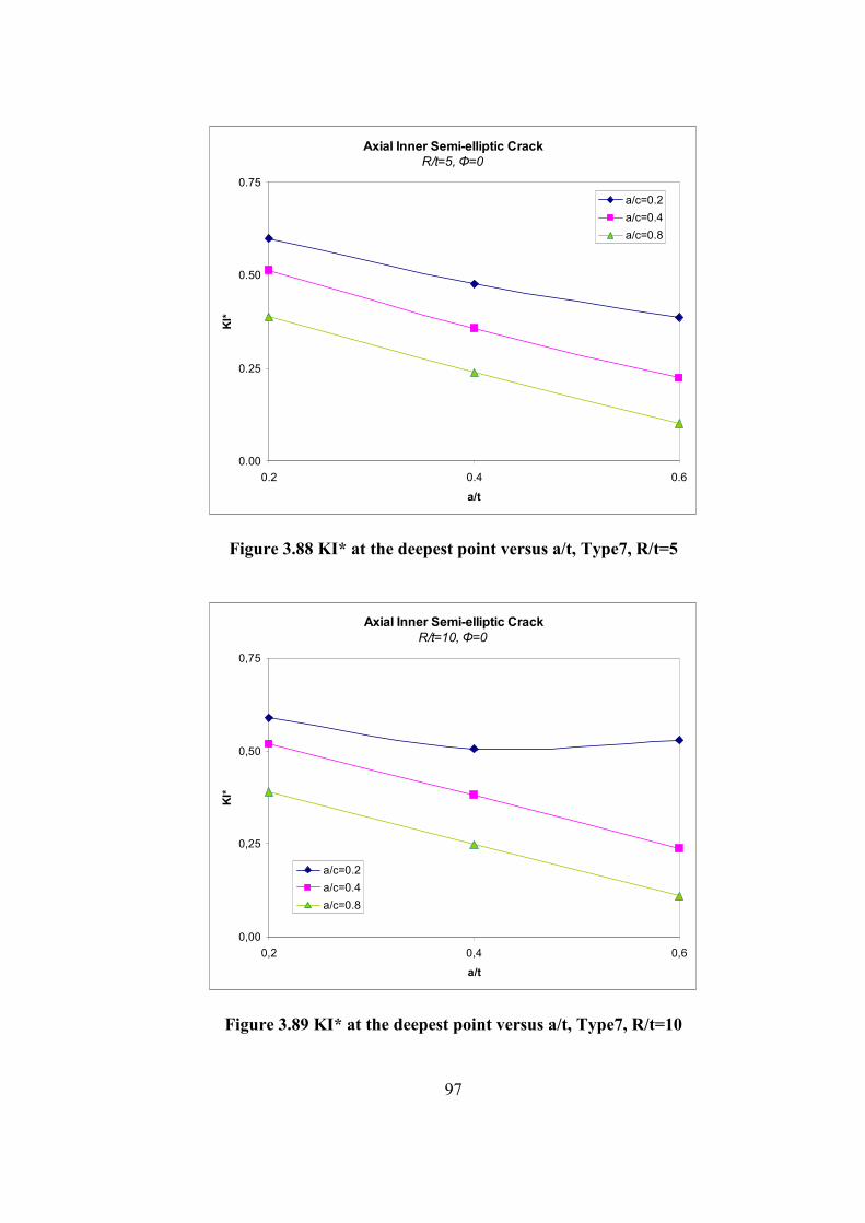
97
Axial Inner Semi-elliptic Crack
R/t=5, Φ=0
0.00
0.25
0.50
0.75
0.2 0.4 0.6
a/t
KI*
a/c=0.2
a/c=0.4
a/c=0.8
Figure 3.88 KI* at the deepest point versus a/t, Type7, R/t=5
Axial Inner Semi-elliptic Crack
R/t=10, Φ=0
0,00
0,25
0,50
0,75
0,2 0,4 0,6
a/t
KI*
a/c=0.2
a/c=0.4
a/c=0.8
Figure 3.89 KI* at the deepest point versus a/t, Type7, R/t=10

98
Axial Inner Semi-elliptic Crack
R/t=20, Φ=0
0.00
0.25
0.50
0.75
0.2 0.4 0.6
a/t
KI*
a/c=0.2
a/c=0.4
a/c=0.8
Figure 3.90 KI* at the deepest point versus a/t, Type7, R/t=20

99
Table 3.7 KI* for thermal loaded partial inner axial crack
R/t a/t a/c a
(mm) Φ=0 11.25 22.5 33.75 45 56.25 67.5 78.75 90
0.2 2 0.60 0.60 0.60 0.59 0.57 0.54 0.48 0.42 0.41
0.4 2 0.51 0.50 0.51 0.51 0.50 0.49 0.47 0.46 0.48 0.2
0.8 2 0.39 0.38 0.40 0.40 0.42 0.43 0.45 0.49 0.51
0.2 4 0.48 0.48 0.49 0.51 0.51 0.50 0.48 0.44 0.43
0.4 4 0.36 0.35 0.37 0.38 0.40 0.41 0.43 0.44 0.47 0.4
0.8 4 0.24 0.24 0.26 0.28 0.31 0.35 0.39 0.45 0.48
0.2 6 0.39 0.44 0.45 0.49 0.51 0.50 0.49 0.47 0.48
0.4 6 0.22 0.23 0.26 0.29 0.33 0.38 0.41 0.45 0.51
5
0.6
0.8 6 0.10 0.11 0.13 0.17 0.21 0.27 0.34 0.41 0.47
0.2 1 0.59 0.59 0.60 0.59 0.57 0.53 0.49 0.42 0.40
0.4 1 0.52 0.52 0.52 0.52 0.51 0.49 0.47 0.46 0.49 0.2
0.8 1 0.39 0.39 0.40 0.41 0.42 0.43 0.45 0.48 0.51
0.2 2 0.51 0.50 0.51 0.52 0.52 0.51 0.48 0.43 0.29
0.4 2 0.38 0.38 0.40 0.41 0.43 0.44 0.44 0.46 0.49 0.4
0.8 2 0.25 0.25 0.27 0.29 0.32 0.36 0.40 0.45 0.49
0.2 3 0.53 0.53 0.54 0.54 0.53 0.51 0.48 0.42 0.41
0.4 3 0.24 0.25 0.27 0.31 0.35 0.39 0.42 0.46 0.51
10
0.6
0.8 3 0.11 0.12 0.14 0.18 0.23 0.28 0.35 0.43 0.48
0.2 0.5 0.60 0.60 0.60 0.59 0.56 0.53 0.47 0.41 0.40
0.4 0.5 0.51 0.51 0.52 0.51 0.50 0.49 0.47 0.46 0.48 0.2
0.8 0.5 0.39 0.39 0.40 0.40 0.41 0.43 0.45 0.48 0.51
0.2 1 0.50 0.51 0.53 0.53 0.53 0.51 0.48 0.43 0.43
0.4 1 0.38 0.39 0.40 0.42 0.43 0.44 0.44 0.45 0.50 0.4
0.8 1 0.25 0.26 0.27 0.29 0.32 0.36 0.40 0.45 0.49
0.2 1.5 0.41 0.41 0.44 0.47 0.49 0.51 0.50 0.47 0.48
0.4 1.5 0.24 0.24 0.25 0.27 0.29 0.35 0.43 0.46 0.51
20
0.6
0.8 1.5 0.11 0.12 0.15 0.18 0.23 0.28 0.35 0.42 0.49
KI* at the deepest point is greater than KI* at the surface point for the cases
a/c and a/t is small. As a/c and a/t increases, KI* at surface point is greater than
KI* at the deepest point.
As a/t increases, crack propagates at the surface point rather than deepest
point.

100
3.2.2.Thermally loaded-Partial Axial Outer Semi-elliptic Crack
Crack front angle 0 is the deepest point and angle 90 is the surface point.
Steady-state thermal load is applied to the structure. Inside temperature is higher
than the outer temperature. Inner temperature is applied 100°C and outer
temperature is applied -100°C. Results are obtained for different R/t, a/t and a/c
values. R is 50mm for all cases but a, c and t change. Results are obtained for the
following ranges;
R/t = 5, 10 and 20
a/t = 0.2, 0.4 and 0.6
a/c = 0.2, 0.4 and 0.8
Axial Outer Semi-elliptic Crack
R/t=5, a/t=0.2
0.30
0.35
0.40
0.45
0.50
0.55
0.60
0.65
0 11.25 22.5 33.75 45 56.25 67.5 78.75 90
Φ
KI*
a/c=0.2
a/c=0.4
a/c=0.8
Figure 3.91 KI* versus Φ, Type8, R/t=5, a/t=0.2

101
Axial Outer Semi-elliptic Crack
R/t=5, a/t=0.4
0.20
0.30
0.40
0.50
0.60
0 11.25 22.5 33.75 45 56.25 67.5 78.75 90
Φ
KI*
a/c=0.2
a/c=0.4
a/c=0.8
Figure 3.92 KI* versus Φ, Type8, R/t=5, a/t=0.4
Axial Outer Semi-elliptic Crack
R/t=5, a/t=0.6
0.10
0.20
0.30
0.40
0.50
0.60
0 11.25 22.5 33.75 45 56.25 67.5 78.75 90
Φ
KI*
a/c=0.2
a/c=0.4
a/c=0.8
Figure 3.93 KI* versus Φ, Type8, R/t=5, a/t=0.6

102
Axial Outer Semi-elliptic Crack
R/t=10, a/t=0.2
0.35
0.40
0.45
0.50
0.55
0.60
0.65
0 11.25 22.5 33.75 45 56.25 67.5 78.75 90
Φ
KI*
a/c=0.2
a/c=0.4
a/c=0.8
Figure 3.94 KI* versus Φ, Type8, R/t=10, a/t=0.2
Axial Outer Semi-elliptic Crack
R/t=10, a/t=0.4
0.20
0.30
0.40
0.50
0.60
0 11.25 22.5 33.75 45 56.25 67.5 78.75 90
Φ
KI*
a/c=0.2
a/c=0.4
a/c=0.8
Figure 3.95 KI* versus Φ, Type8, R/t=10, a/t=0.4

103
Axial Outer Semi-elliptic Crack
R/t=10, a/t=0.6
0.10
0.20
0.30
0.40
0.50
0.60
0 11.25 22.5 33.75 45 56.25 67.5 78.75 90
Φ
KI*
a/c=0.2
a/c=0.4
a/c=0.8
Figure 3.96 KI* versus Φ, Type8, R/t=10, a/t=0.6
Axial Outer Semi-elliptic Crack
R/t=20, a/t=0.2
0.35
0.45
0.55
0.65
0 11.25 22.5 33.75 45 56.25 67.5 78.75 90
Φ
KI*
a/c=0.2
a/c=0.4
a/c=0.8
Figure 3.97 KI* versus Φ, Type8, R/t=20, a/t=0.2

104
Axial Outer Semi-elliptic Crack
R/t=20, a/t=0.4
0.20
0.30
0.40
0.50
0.60
0 11.25 22.5 33.75 45 56.25 67.5 78.75 90
Φ
KI*
a/c=0.2
a/c=0.4
a/c=0.8
Figure 3.98 KI* versus Φ, Type8, R/t=20, a/t=0.4
Axial Outer Semi-elliptic Crack
R/t=20, a/t=0.6
0.10
0.20
0.30
0.40
0.50
0.60
0 11.25 22.5 33.75 45 56.25 67.5 78.75 90
Φ
KI*
a/c=0.2
a/c=0.4
a/c=0.8
Figure 3.99 KI* versus Φ, Type8, R/t=20, a/t=0.6

105
Axial Outer Semi-elliptic Crack
R/t=5, Φ=0
0.10
0.20
0.30
0.40
0.50
0.60
0.70
0.2 0.4 0.6
a/t
KI*
a/c=0.2
a/c=0.4
a/c=0.8
Figure 3.100 KI* at the deepest point versus a/t, Type8, R/t=5
Axial Outer Semi-elliptic Crack
R/t=10, Φ=0
0.10
0.20
0.30
0.40
0.50
0.60
0.2 0.4 0.6
a/t
KI*
a/c=0.2
a/c=0.4
a/c=0.8
Figure 3.101 KI* at the deepest point versus a/t, Type8, R/t=10

106
Axial Outer Semi-elliptic Crack
R/t=20, Φ=0
0.10
0.20
0.30
0.40
0.50
0.60
0.70
0.2 0.4 0.6
a/t
KI*
a/c=0.2
a/c=0.4
a/c=0.8
Figure 3.102 KI* at the deepest point versus a/t, Type8, R/t=20

107
Table 3.8 KI* for thermal loaded partial outer axial crack
R/t a/t a/c a
(mm) Φ=0 11.25 22.5 33.75 45 56.25 67.5 78.75 90
0.2 2 0.60 0.59 0.59 0.57 0.55 0.51 0.45 0.38 0.36
0.4 2 0.51 0.50 0.51 0.50 0.49 0.47 0.44 0.43 0.44 0.2
0.8 2 0.38 0.38 0.39 0.39 0.40 0.41 0.43 0.44 0.46
0.2 4 0.55 0.55 0.57 0.56 0.53 0.50 0.46 0.41 0.39
0.4 4 0.42 0.41 0.43 0.43 0.44 0.44 0.44 0.44 0.44 0.4
0.8 4 0.27 0.27 0.29 0.30 0.33 0.36 0.39 0.44 0.44
0.2 6 0.53 0.53 0.55 0.55 0.54 0.53 0.49 0.45 0.52
0.4 6 0.33 0.33 0.35 0.38 0.41 0.43 0.45 0.47 0.50
5
0.6
0.8 6 0.15 0.15 0.18 0.21 0.26 0.31 0.37 0.43 0.46
0.2 1 0.60 0.60 0.60 0.58 0.56 0.52 0.47 0.40 0.39
0.4 1 0.51 0.51 0.52 0.51 0.50 0.48 0.46 0.44 0.46 0.2
0.8 1 0.39 0.38 0.39 0.40 0.40 0.42 0.44 0.46 0.48
0.2 2 0.55 0.55 0.56 0.55 0.54 0.52 0.48 0.42 0.42
0.4 2 0.41 0.41 0.43 0.43 0.44 0.45 0.45 0.45 0.48 0.4
0.8 2 0.26 0.27 0.28 0.30 0.33 0.36 0.40 0.44 0.48
0.2 3 0.52 0.52 0.54 0.55 0.55 0.54 0.52 0.47 0.47
0.4 3 0.30 0.30 0.33 0.36 0.40 0.43 0.45 0.48 0.52
10
0.6
0.8 3 0.14 0.14 0.17 0.20 0.25 0.30 0.36 0.44 0.48
0.2 0.5 0.60 0.60 0.60 0.58 0.56 0.52 0.46 0.40 0.39
0.4 0.5 0.52 0.52 0.52 0.51 0.50 0.49 0.46 0.45 0.41 0.2
0.8 0.5 0.39 0.39 0.39 0.40 0.41 0.42 0.44 0.47 0.50
0.2 1 0.54 0.53 0.55 0.54 0.54 0.52 0.48 0.43 0.44
0.4 1 0.41 0.41 0.42 0.43 0.44 0.45 0.45 0.46 0.50 0.4
0.8 1 0.26 0.26 0.28 0.30 0.33 0.36 0.40 0.45 0.49
0.2 1.5 0.49 0.50 0.52 0.54 0.55 0.55 0.53 0.49 0.50
0.4 1.5 0.28 0.29 0.31 0.35 0.38 0.42 0.44 0.48 0.53
20
0.6
0.8 1.5 0.13 0.14 0.16 0.20 0.24 0.30 0.36 0.44 0.50
Similar to the thermal loaded inner axial crack case, KI* at the deepest point
is greater than KI* at the surface point for the cases a/c and a/t is small. As a/c and
a/t increases, KI* at surface point is greater than KI* at the deepest point.
As a/t increases, crack propagates at the surface point rather than deepest
point.

108
3.2.3.Thermally loaded- Circumferential Inner Semi-elliptic Crack
Crack front angle 0 is the deepest point. Steady-state thermal load is applied
to the structure. Inside temperature is lower than the outer temperature. Inner
temperature is applied -100°C and outer temperature is applied 100°C. Results are
obtained for different R/t, a/t and a/c values. R is 50mm for all cases but a, c and t
change. Results are obtained for the following ranges;
R/t = 5, 10 and 20
a/t = 0.2, 0.3 and 0.4
a/c = 0.2, 0.4 and 0.8
Partial Circumferential Inner Semi-elliptic Crack
R/t=5, a/t=0.2
0.30
0.35
0.40
0.45
0.50
0.55
0.60
0.65
0.70
0 22.5 45 67.5 90
Φ
KI*
a/c=0.2
a/c=0.4
a/c=0.8
Figure 3.103 KI* versus Φ, Type9, R/t=5, a/t=0.2

109
Partial Circumferential Inner Semi-elliptic Crack
R/t=5, a/t=0.3
0.15
0.20
0.25
0.30
0.35
0.40
0.45
0.50
0.55
0.60
0.65
0 22.5 45 67.5 90
Φ
KI*
a/c=0.2
a/c=0.4
a/c=0.8
Figure 3.104 KI* versus Φ, Type9, R/t=5, a/t=0.3
Partial Circumferential Inner Semi-elliptic Crack
R/t=5, a/t=0.4
0.00
0.05
0.10
0.15
0.20
0.25
0.30
0.35
0.40
0.45
0.50
0.55
0.60
0.65
0 22.5 45 67.5 90
Φ
KI*
a/c=0.2
a/c=0.4
a/c=0.8
Figure 3.105 KI* versus Φ, Type9, R/t=5, a/t=0.4

110
Partial Circumferential Inner Semi-elliptic Crack
R/t=10, a/t=0.2
0.30
0.35
0.40
0.45
0.50
0.55
0.60
0.65
0.70
0 22.5 45 67.5 90
Φ
KI*
a/c=0.2
a/c=0.4
a/c=0.8
Figure 3.106 KI* versus Φ, Type9, R/t=10, a/t=0.2
Partial Circumferential Inner Semi-elliptic Crack
R/t=10, a/t=0.3
0.30
0.35
0.40
0.45
0.50
0.55
0.60
0 22.5 45 67.5 90
Φ
KI*
a/c=0.2
a/c=0.4
a/c=0.8
Figure 3.107 KI* versus Φ, Type9, R/t=10, a/t=0.3

111
Partial Circumferential Inner Semi-elliptic Crack
R/t=10, a/t=0.4
0.20
0.25
0.30
0.35
0.40
0.45
0.50
0.55
0.60
0 22.5 45 67.5 90
Φ
KI*
a/c=0.2
a/c=0.4
a/c=0.8
Figure 3.108 KI* versus Φ, Type9, R/t=10, a/t=0.4
Partial Circumferential Inner Semi-elliptic Crack
R/t=20, a/t=0.2
0.35
0.40
0.45
0.50
0.55
0.60
0.65
0 22.5 45 67.5 90
Φ
KI*
a/c=0.2
a/c=0.4
a/c=0.8
Figure 3.109 KI* versus Φ, Type9, R/t=20, a/t=0.2

112
Partial Circumferential Inner Semi-elliptic Crack
R/t=20, a/t=0.3
0.30
0.35
0.40
0.45
0.50
0.55
0.60
0.65
0 22.5 45 67.5 90
Φ
KI*
a/c=0.2
a/c=0.4
a/c=0.8
Figure 3.110 KI* versus Φ, Type9, R/t=20, a/t=0.3
Partial Circumferential Inner Semi-elliptic Crack
R/t=20, a/t=0.4
0.20
0.25
0.30
0.35
0.40
0.45
0.50
0.55
0.60
0.65
0 22.5 45 67.5 90
Φ
KI*
a/c=0.2
a/c=0.4
a/c=0.8
Figure 3.111 KI* versus Φ, Type9, R/t=20, a/t=0.4

113
Partial Circumferential Inner Semi-elliptic Crack
R/t=5, Φ=0
0.20
0.30
0.40
0.50
0.60
0.70
0.2 0.3 0.4
a/t
KI*
a/c=0.2
a/c=0.4
a/c=0.8
Figure 3.112 KI* at the deepest point versus a/t, Type9, R/t=5
Partial Circumferential Inner Semi-elliptic Crack
R/t=10, Φ=0
0.20
0.30
0.40
0.50
0.60
0.70
0.2 0.3 0.4
a/t
KI*
a/c=0.2
a/c=0.4
a/c=0.8
Figure 3.113 KI* at the deepest point versus a/t, Type9, R/t=10

114
Partial Circumferential Inner Semi-elliptic Crack
R/t=20, Φ=0
0.20
0.30
0.40
0.50
0.60
0.70
0.2 0.3 0.4
a/t
KI*
a/c=0.2
a/c=0.4
a/c=0.8
Figure 3.114 KI* at the deepest point versus a/t, Type9, R/t=20

115
Table 3.9 KI* for thermal loaded partial inner circumferential crack
R/t a/t a/c a
(mm) Φ=0 22.50 45 67.50 90
0.2 2 0.63 0.62 0.56 0.44 0.31
0.4 2 0.53 0.53 0.50 0.47 0.49 0.2
0.8 2 0.41 0.41 0.42 0.46 0.55
0.2 3 0.58 0.55 0.46 0.31 0.22
0.4 3 0.46 0.46 0.45 0.42 0.46 0.3
0.8 3 0.33 0.34 0.37 0.42 0.52
0.2 4 0.52 0.46 0.30 0.15 0.11
0.4 4 0.38 0.38 0.38 0.37 0.41
5
0.4
0.8 4 0.26 0.28 0.32 0.50 0.50
0.2 1 0.62 0.62 0.58 0.49 0.37
0.4 1 0.53 0.53 0.51 0.47 0.51 0.2
0.8 1 0.40 0.41 0.43 0.46 0.53
0.2 1.5 0.57 0.57 0.53 0.44 0.32
0.4 1.5 0.46 0.47 0.46 0.45 0.49 0.3
0.8 1.5 0.33 0.35 0.38 0.43 0.53
0.2 2 0.53 0.52 0.46 0.36 0.28
0.4 2 0.39 0.41 0.42 0.42 0.49
10
0.4
0.8 2 0.26 0.28 0.33 0.40 0.53
0.2 0.5 0.61 0.61 0.58 0.48 0.39
0.4 0.5 0.52 0.52 0.50 0.46 0.49 0.2
0.8 0.5 0.40 0.40 0.42 0.45 0.53
0.2 0.8 0.57 0.57 0.55 0.47 0.38
0.4 0.8 0.49 0.50 0.50 0.48 0.54 0.3
0.8 0.8 0.33 0.34 0.38 0.43 0.52
0.2 1 0.53 0.53 0.51 0.45 0.37
0.4 1 0.40 0.41 0.43 0.43 0.51
20
0.4
0.8 1 0.26 0.28 0.33 0.40 0.51
As a/c increases, KI* at surface points become larger than KI* at deepest
point. As a/t increases, KI* decreases for same R/t and a/c values.

116
3.2.4.Thermally loaded-Circumferential Outer Semi-elliptic Crack
Crack front angle 0 is the deepest point. Steady-state thermal load is applied
to the structure. Inside temperature is higher than the outer temperature. Inner
temperature is applied 100°C and outer temperature is applied -100°C. Results are
obtained for different R/t, a/t and a/c values. R is 50mm for all cases but a, c and t
change. Results are obtained for the following ranges;
R/t = 5, 10 and 20
a/t = 0.2, 0.3 and 0.4
a/c = 0.2, 0.4 and 0.8
Partial Circumferential Outer Semi-elliptic Crack
R/t=5, a/t=0.2
0.30
0.35
0.40
0.45
0.50
0.55
0.60
0.65
0 11.25 22.5 33.75 45
Φ
KI*
a/c=0.2
a/c=0.4
a/c=0.8
Figure 3.115 KI* versus Φ, Type10, R/t=5, a/t=0.2

117
Partial Circumferential Outer Semi-elliptic Crack
R/t=5, a/t=0.3
0.20
0.25
0.30
0.35
0.40
0.45
0.50
0.55
0.60
0 11.25 22.5 33.75 45
Φ
KI*
a/c=0.2
a/c=0.4
a/c=0.8
Figure 3.116 KI* versus Φ, Type10, R/t=5, a/t=0.3
Partial Circumferential Outer Semi-elliptic Crack
R/t=5, a/t=0.4
0.20
0.25
0.30
0.35
0.40
0.45
0.50
0.55
0 11.25 22.5 33.75 45
Φ
KI*
a/c=0.2
a/c=0.4
a/c=0.8
Figure 3.117 KI* versus Φ, Type10, R/t=5, a/t=0.4

118
Partial Circumferential Outer Semi-elliptic Crack
R/t=10, a/t=0.2
0.30
0.35
0.40
0.45
0.50
0.55
0.60
0.65
0 11.25 22.5 33.75 45
Φ
KI*
a/c=0.2
a/c=0.4
a/c=0.8
Figure 3.118 KI* versus Φ, Type10, R/t=10, a/t=0.2
Partial Circumferential Outer Semi-elliptic Crack
R/t=10, a/t=0.3
0.20
0.25
0.30
0.35
0.40
0.45
0.50
0.55
0.60
0.65
0 11.25 22.5 33.75 45
Φ
KI*
a/c=0.2
a/c=0.4
a/c=0.8
Figure 3.119 KI* versus Φ, Type10, R/t=10, a/t=0.3

119
Partial Circumferential Outer Semi-elliptic Crack
R/t=10, a/t=0.4
0.20
0.25
0.30
0.35
0.40
0.45
0.50
0.55
0.60
0.65
0 11.25 22.5 33.75 45
Φ
KI*
a/c=0.2
a/c=0.4
a/c=0.8
Figure 3.120 KI* versus Φ, Type10, R/t=10, a/t=0.4
Partial Circumferential Outer Semi-elliptic Crack
R/t=20, a/t=0.2
0.30
0.35
0.40
0.45
0.50
0.55
0.60
0.65
0 11.25 22.5 33.75 45
Φ
KI*
a/c=0.2
a/c=0.4
a/c=0.8
Figure 3.121 KI* versus Φ, Type10, R/t=20, a/t=0.2

120
Partial Circumferential Outer Semi-elliptic Crack
R/t=20, a/t=0.3
0.25
0.30
0.35
0.40
0.45
0.50
0.55
0.60
0.65
0 11.25 22.5 33.75 45
Φ
KI*
a/c=0.2
a/c=0.4
a/c=0.8
Figure 3.122 KI* versus Φ, Type10, R/t=20, a/t=0.3
Partial Circumferential Outer Semi-elliptic Crack
R/t=20, a/t=0.4
0.20
0.25
0.30
0.35
0.40
0.45
0.50
0.55
0.60
0.65
0 11.25 22.5 33.75 45
Φ
KI*
a/c=0.2
a/c=0.4
a/c=0.8
Figure 3.123 KI* versus Φ, Type10, R/t=20, a/t=0.4

121
Partial Circumferential Outer Semi-elliptic Crack
R/t=5, Φ=0
0.20
0.25
0.30
0.35
0.40
0.45
0.50
0.55
0.60
0.2 0.3 0.4
a/t
KI*
a/c=0.2
a/c=0.4
a/c=0.8
Figure 3.124 KI* at the deepest point versus a/t, Type10, R/t=5
Partial Circumferential Outer Semi-elliptic Crack
R/t=10, Φ=0
0.20
0.25
0.30
0.35
0.40
0.45
0.50
0.55
0.60
0.2 0.3 0.4
a/t
KI*
a/c=0.2
a/c=0.4
a/c=0.8
Figure 3.125 KI* at the deepest point versus a/t, Type10, R/t=10

122
Partial Circumferential Outer Semi-elliptic Crack
R/t=20, Φ=0
0.20
0.25
0.30
0.35
0.40
0.45
0.50
0.55
0.60
0.65
0.2 0.3 0.4
a/t
KI*
a/c=0.2
a/c=0.4
a/c=0.8
Figure 3.126 KI* at the deepest point versus a/t, Type10, R/t=20

123
Table 3.10 KI* for thermal loaded partial outer circumferential crack
R/t a/t a/c a
(mm) Φ=0 11.25 22.5 33.75 45
0.2 2 0.55 0.55 0.55 0.54 0.49
0.4 2 0.48 0.48 0.49 0.48 0.47 0.2
0.8 2 0.36 0.36 0.37 0.37 0.38
0.2 3 0.48 0.49 0.50 0.50 0.45
0.4 3 0.40 0.40 0.42 0.42 0.42 0.3
0.8 3 0.30 0.30 0.32 0.33 0.35
0.2 4 0.42 0.43 0.46 0.47 0.42
0.4 4 0.35 0.36 0.38 0.40 0.42
5
0.4
0.8 4 0.24 0.24 0.26 0.28 0.30
0.2 1 0.58 0.57 0.58 0.57 0.55
0.4 1 0.50 0.50 0.50 0.50 0.48 0.2
0.8 1 0.38 0.38 0.39 0.40 0.40
0.2 1.5 0.52 0.52 0.53 0.53 0.51
0.4 1.5 0.43 0.44 0.45 0.46 0.45 0.3
0.8 1.5 0.31 0.32 0.33 0.34 0.36
0.2 2 0.47 0.47 0.50 0.51 0.50
0.4 2 0.37 0.38 0.40 0.42 0.43
10
0.4
0.8 2 0.25 0.25 0.27 0.29 0.32
0.2 0.5 0.59 0.59 0.59 0.58 0.54
0.4 0.5 0.51 0.51 0.52 0.51 0.49 0.2
0.8 0.5 0.38 0.38 0.39 0.40 0.40
0.2 0.8 0.54 0.54 0.55 0.54 0.52
0.4 0.8 0.45 0.45 0.46 0.46 0.45 0.3
0.8 0.8 0.32 0.32 0.33 0.34 0.36
0.2 1 0.49 0.50 0.52 0.52 0.51
0.4 1 0.38 0.39 0.40 0.42 0.43
20
0.4
0.8 1 0.25 0.26 0.27 0.29 0.32
As a/c increases, KI* at surface points become larger than KI* at deepest
point. As a/t increases, KI* decreases for same R/t and a/c values.

124
CHAPTER 4
4. DISCUSSION
The results are obtained for different R/t, a/t and a/c values. As it can be
seen from the graphics, while R/t increases, KI* values increases for the inner
pressure applied cases. For tensile and thermal load applied cases the values do
not change so much. Also when R/t and a/t is constant, KI* decreases as a/c
increases.
In most cases maximum KI* is at the deepest point. But in some cases
maximum KI* can be at surface point depending on the geometry and the loading.
Crack propagates at the point which has the maximum KI*. In Figure 4.1, a crack
propagating at the surface point is shown.
In inner surface semi-elliptic crack cases, as a/c gets closer to 1 (means
circular crack), KI* of the surface point increases, while KI* of the deepest point
decreases. This explains that why cracks propagate to an elliptic shape. When a/c
is 1, KI* of surface points forces the crack propagate at the surface and when
crack gets an elliptic shape KI* of the surface point decreases and stops
propagating at surface.
Figure 4.1 Propagation of a circumferential inner crack
Crack front
Inner surface of cylinder
Propagates at surface point

125
The model used in this study is verified with four different cases. The first
one was embedded semi-elliptic crack in an infinite medium. Results from closed
formulas and ANSYS were compared. The results matched almost exactly.
For the other cases, ANSYS results were matched with some a/c and R/t
values, and for other a/c and R/t values the results were parallel but different.
Each case considered in this study was valid for spesific a/c and R/t ranges. As
these values get out of the specified range, the results obtained from this study get
invalid. So, these results are case dependent. This is because of the nature of the
problem. At the moment, there is no generalized exact formula for all types of
cracks. It is believed that this study was able to create a generalized crack model
with an acceptable error. APDL codes are generated to achieve this result. Finite
element analysis is a computer dependent method. Therefore in the following
years, due to the development in computer technology, this method will also
develope.

126
CHAPTER 5
5. CONCLUSION AND FUTURE WORK
APDL codes are developed for ten cases in this study. Six of them are for
mechanical loading and the remaining four of them are for thermal loading of
different geometries. Thermal load has not been applied to the geometries
containing embedded cracks. The results are obtained for different R/t, a/c and a/t
values. Ten APDL codes are developed to solve each ten geometries with
different R/t, a/c and a/t values. This goal is achieved mostly. But for some cases,
mostly the cases with sharp elliptical path (e.g. a/c=0.2), meshing can not be done
with a straightforward way. Special effort is needed. Element sizes are aligned
according to the geometry.
This thesis study can be extended by the following subjects
• In this thesis study, homogeneous isotropic material is considered. In the
future, FGM (Functionally Graded Material) can also be considered.
• Elasto-plastic fracture mechanics can be considered with these crack
types.
• This work can be extended with different dimensions of structure and
crack.
• Conical shapes can also be considered.

127
REFERENCES
[1] Gery Wilkowsky, Leak-Before-Break: What Does It Really Mean? Journal of
Pressure Vessel Technology, August 2000, Volume 122, Issue 3, pp. 267-272
[2] A. Zahoor, Closed Form expressions for Fracture Mechanics Analysis of
Cracked pipes. Journal of Pressure Vessel Technology 1985, vol.107, pp.203-
205.
[3] Raju IS, Newman Jr C. Stress intensity factors for internal and external surface
crack in cylindrical vessels. Journal of Pressure Vessel Technology 1982,
vol.104, 293–8.
[4] A.R.Shahani, S.M.Nabavi, Closed form stress intensity factors for a semi-
elliptical crack in a thick-walled cylinder under thermal stress. International
Journal of Fatigue 28, 2006, pp.926-933
[5] A.R.Shahani, S.M.Nabavi, Transient Thermal stress intensity factors for an
internal longitudinal semi-elliptical crack in a thick-walled cylinder.
Engineering Fracture Mechanics 74, 2007, pp.2585-2602
[6] A.R.Shahani, S.M.Nabavi, Calculation of stress intensity factors for a
longitudinal semi-elliptical crack in a finite-length thick-walled cylinder.
Fatigue and Fracture of Engineering Materials and Structures 31, 2008, pp.85-
94
[7] A.R.Shahani, S.E. Habibi, Stress intensity factors in a hollow cylinder
containing a circumferential semi-elliptical crack subjected to combined
loading. International journal of Fatigue, 29, 2007, pp. 128-140

128
[8] Naoki Miura, Yukio Takahashi, Hiroshi Shibamoto, Kazuhiko Inoue,
Comparison of stress intensity factor solutions for cylinders with axial and
circumferential cracks, Nuclear Engineering and Design 238, 2008, pp.423-
434
[9] B.Acar, Finite Element Analysis of Fracture Mechanics Problems, Master
Thesis, June 1997
[10] G.Atalay, A Computational Elastic Fracture Analysis of Cylindrical and
Conical Structures, September 2002
[11] Ö.Đnan, Three Dimensional Fracture Analysis of FGM Coatings, September
2004
[12] B.Sabuncuoğlu, Fatigue Crack Growth Analysis Models for Functionally
Graded Materials, January 2006
[13] S.Köşker, Three Dimensional Mixed Mode Fracture Analysis of Functionally
Graded Materials, September 2007
[14] Release 11.0 Documentation for ANSYS
[15] Fracture Mechanics: Fundamentals and Applications, Anderson, T.L., 2005