computational fracture mechanics of concrete …framcos.org/framcos-6/405.pdf · computational...
TRANSCRIPT
Computational Fracture Mechanics of Concrete Structures: A Retrospectivethrough Multiple Lenses
J. M. Emery, J. D. Hochhalther & A. R. IngraffeaCornell University, Ithaca, NY
ABSTRACT: The history of the application of computational fracture mechanics to concrete structures, now5 decades old, is interesting from many perspectives. In this paper, a retrospective of computational fracturemechanics in concrete structures (ComFraMCoS) is presented through five lenses. These lenses clarify researchtrends through an historical overview. We intend to interlace the views through these lenses to sometimesoffer admittedly slanted insights, to question the status quo and to provoke thought and discussion about futuredirections of ComFraMCoS.
1 INTRODUCTION
One can easily support the argument that the distinctfield of computational fracture mechanics itself arosefrom concerns about cracking in concrete structures,both plain (e.g. dams, Clough 1962) and reinforced(e.g. beams, Ngo & Scordelis 1967). In past publica-tions there have been many well-written reviews ofthe work in computational fracture mechanics in con-crete structures (ComFraMCoS). Therefore, the goalof this paper is not to serve as a complete summaryor technical report, but to extrapolate from the historyand suggest future directions for ComFraMCoS re-search. To do this, we choose a retrospective through5 lenses: computational resources, software, physics,practice and dimensionality.
The Lens of Computational Resources – GeorgeIrwin was doing his best thinking at the same timethat electronic computation was being invented. So itwas serendipity that the field of fracture mechanicscould hop on and ride the still growing wave of com-putational resources our generation has been luckyto have. But, with teraflops of power, petabytes ofstorage, and amazing visualization capabilities avail-able for the taking, why has ComFraMCoS appearedmostly to languish on the fringes of this digital rev-olution? What is inhibiting our field from unleashingall that power on our most fundamental problems?
The Lens of Software – How many distinct Com-FraMCoS programs have been written by graduatestudents worldwide? How many of these programshave broken new ground in numerical methods for so-lution of boundary value problems, as opposed to re-
vealing new insights into the physical processes theyseek to simulate? We see improvements in softwareas quite different from enhanced understanding of thephysics driving fracture processes. The ComFraM-CoS community can take pride in contributing signif-icantly to the invention/evolution of smeared crack-ing, damage mechanics, cohesive constitutive mod-els, meshfree methods, and enriched element meth-ods. But, have we perhaps been a bit too distractedby the novelty of variations in such numerical meth-ods for software implementation rather than findingways of applying it to answer fundamental questionsheretofore intractable?
The Lens of Physics – How much more about in-cubation, nucleation, microscopically small and largepropagation of cracks in reinforced concrete (RC) dowe really understand from first principles now com-pared to 40 years ago? Can the surrogates for physicssuch as stress intensity factors, damage measures,critical energy release rates, cohesive strengths, what-ever your favorite flavor of fracture mechanics, evercapture sufficiently well what is actually happening ina real concrete structure? Our answer is no. What willbe required to focus the current generation of grad-uate students on multidisciplinary approaches, com-bining computational science and materials science,condensed matter physics and chemistry, and struc-tural mechanics, needed for breakthrough discoveriesthat will lead to fundamental knowledge in the analy-sis and design of RC structures?
The Lens of Practice – Is it amazing or embarrass-ing that after 5 decades, a period during which any

number of other fields of engineering have been born,matured, and completely remade themselves multi-ple times (e.g., biomedical engineering, MEMS engi-neering) ComFraMCoS has had so little tangible ef-fect on everyday practice in the analysis and designof concrete structures? It was perhaps naive to thinkthat practice in the field of concrete structures wouldquickly adopt the more physics-based rules of behav-ior that have evolved from academic research intothe fracture mechanics of concrete. Witness the two-decade struggle to modify the ACI code for size ef-fect in shear. Why haven’t full-field, non-linear mod-eling approaches evolved from ComFraMCoS beenadopted?
The Lens of Dimensionality – This lens has twofoci: the dimension of the scale of investigation, con-tinuum, meso, micro and atomistic; and the dimen-sion of the space of inquiry, 2D or 3D. More than20 years ago, truly exciting work began to appear inthe ComFraMCoS literature in which the constituentsof concrete and small but important details of re-inforcement were explicitly represented in both ge-ometry and mesh models. We view these early ef-forts as precursors to what is now recognized as mul-tiscale modeling. Why, however, in 2007 does themajority of the new ComFraMCoS journal literaturehave an exclusively continuum focus? Allied fieldsof composites and even metals have turned their focidownscale towards an integration of condensed mat-ter physics, materials science, and structural mechan-ics, purposely injecting as much geometrical realismat each length scale as possible into their simulations.Why is the same approach not being taken, for themost part, in ComFraMCoS? And, why, in 2007, withall those teraflops and petabytes lying around, andwith uncertainty of planar behavior ever really exist-ing anywhere, is the vast majority of the work in Com-FraMCoS still 2D?
It is common to assume at least four distinct lengthscales comprising concrete: structural, mesoscale, mi-croscale and nanoscale. At the structural length scale,concrete is treated as homogeneous and elastic orelasto-plastic, and linear elastic fracture mechanics isconsidered applicable for some geometries.
At the mesoscale it is common to include threematerial phases: aggregate, mortar, and the interfa-cial transition zone (ITZ) between them. The consen-sus is that models of this length scale span volumeswith edge length O(102mm). The microscale is con-sidered to be the hardened cement paste with char-acteristic edge length O(10−1mm). The discontinu-ities at the microstructural length scale are capillarypores. Finally, the nanoscale describes hardened ce-ment gel containing nano-pores (Zaitsev & Wittmann1981, Cusatis et al. 2006).
We will attempt to show that these lenses are not
separate, but rather align, like the multiple lenses ina telescope, each with its own function designed tocontribute to a clear and bright image. Carrying thisanalogy forward, in the last part of the paper we willattempt to rotate this telescope around so that we arepeering into the future of ComFraMCoS.
2 LENS OF COMPUTATIONAL RESOURCESThe field of ComFraMCoS has been relatively lim-ited in its scope of investigation due to the perceivedcomputational demands, viewed broadly, of the mod-els developed. Unlike some of our sister disciplines,we seem to have been more self-saddled by an appar-ent lack of, or lack of will to use, computer power.It is our opinion that this inexplicable malaise can betraced back even to the introduction of smeared crack-ing to avoid the perceived cumbersome and computa-tional demanding geometrical representation of evena single crack.
Indeed, the most detailed, 3D, mesoscale simu-lations, which include the most elaborate materialmodels with the best available physics, are still in-tractable in any material system, but at least in-vestigators in many other material systems are try-ing (McDowell et al. 2003, Attinger & Koumout-sakos 2004)! It is the responsibility of the Com-FraMCoS research community to underpin the prac-tice community with ever-increasing understandingof fracture processes and ever-improving means ofinjecting this understanding into analysis, design,repair, and forensic efforts. “Ever-increasing un-derstanding” means more science and less guess-ing/simplification/approximation/empiricism. There-fore, we cannot allow our vision to be limited by thePC on one’s desk. In the U.S., for example, the Na-tional Science Foundation (NSF) has established theTeraGrid (www.teragrid.org), a computing grid withnear-petaflop scale computers, high-bandwidth con-nectivity, petabyte storage, and exotic visualizationcapabilities, all on a relatively low-traffic 10 Gbpsnetwork. Why are ComFraMCoS researchers not us-ing the TeraGrid? Possible answers include:
1. We have never built models that need such awe-some capability. But at one end of the lengthscale spectrum, surely we have concrete struc-tures with high geometric complexity, dynamicand stochastic boundary conditions, and com-plex cracking events to demand such capability.At the other end of the spectrum, surely we haveconcrete material which, at the mesoscale andbelow, has high geometric complexity, stochasticproperties, coupled-physics phenomena at work,and exquisitely exciting cracking processes toalso demand such simulation capability.
2. A perception that there is overwhelming over-

head in creating and deploying the software com-ponents that can use such capability advanta-geously: the risk is too high compared to thepossible reward. But, our community need notbe overwhelmed by such fantastic capabilities.There is a huge and ever-widening gap betweenwhat’s on the desktop and what is on the Tera-Grid, and there is plenty of opportunity in be-tween to begin to grow the software and in-crease model complexity to use cyberinfrastruc-ture more effectively.
3. A perception that our current models are “goodenough” for practice. But, this answer begs thequestion, because it cuts off the principal respon-sibility of the research community cited above.
It is important to remember that what once was in-tractable is now commonplace; what once took dayson massive supercomputers can now be done in a fewseconds on one’s laptop. This trend is destined to con-tinue, and the field of computational mechanics willbe able to perform elaborate, multiscale, multiphysicssimulations previously only imagined. Why not Com-FraMCoS?
3 LENS OF SOFTWAREOur ComFraMCoS community has been a wellspringof innovation in software and algorithms for rep-resentation of cracking, and for constitutive mod-els for cracking. In the former category, we havegiven, or significantly aided the computational frac-ture community in the development of the follow-ing, in roughly chronological order: smeared crack-ing; discrete cracking with adaptive remeshing; parti-cle and lattice models for cracking; meshfree crack-ing; and enriched element cracking.
In the latter category of achievements, ComFraM-CoS researchers have made vital contributions to: fic-titious cracking concept and cohesive zone models;non-local plasticity; and damage mechanics.
However, with all these sterling innovations to ourcredit, what have they added to our fundamental un-derstanding of cracking processes in concrete? Forexample, what new physical insights at the micro ormeso length scales have arisen from application ofmeshfree or enriched element methods?
Surely, these approaches have made model genera-tion easier, and they should be setting the stage fordevelopment of multiscale, multiphysics simulationsystems that themselves can perform within TeraGrid-like environments. In our opinion, the principal rea-son for creating and applying multiscale simulationsystems is to expose the sources of variability origi-nating with the material structure at the lower lengthscale, and to carry this variability upwards to discover
its effect on variability of strength at the upper, struc-ture scale. When such a process starts at the micro ormeso scale, there will likely be a requirement to rep-resent multiple 3D cracks, to propagate these underas-yet-undiscovered rules of rate and shape change,and to investigate the effects of variability of the ge-ometry and material properties on the resulting evolu-tion of the cracks at such a scale, using, for example,Monte Carlo-like approaches. Feedback to the struc-ture scale would then ensue, and this iterative processwould be continued to a desirable termination state.Figure 1 shows the qualitative process for such a mul-tiscale simulation where the major steps are separatedinto A, B, C, D and E. In Step A, the structural modelis analyzed and a critical region identified. In Step B,local boundary conditions are extracted for placementon the model to undergo higher resolution analysis.In Step C, the local model is analyzed to produce theneeded fields. In Step D, the cracking criterion is en-forced. In Step E, the continuum constitutive model isupdated to reflect the response of the local model. Thesystem outlined in this flowchart begs for a TeraGrid-class environment.
Figure 1. Flowchart describing a multiscale simulationwith information flow between length scales
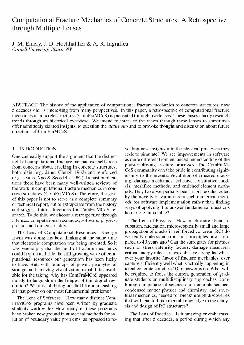
4 LENS OF PHYSICSIn general, the appearance of a crack in a structureand its growth through loading spans multiple timeand length scales. A major focus of past researchhas been to observe the mechanisms of crack growthacross some length scales and use these observationsto develop more accurate models of structural be-havior. However, because of difficulties in observ-ing and simulating phenomena at lower length scales,we often resort to simplified mechanics, rather thanpurely physics-based models. For example, Figure 2shows two distinct length scale views of concrete, mi-croscale (top) and mesoscale (bottom). The crackingprocesses in Figure 2 (bottom) have been simulatedusing continuum mechanics-based models for consti-
tutive behavior and limit states in the hardened ce-ment paste, aggregate and the interface zone. How-ever, this is clearly not a best physics-based approach.Figure 2 (top) shows the lower scale at which, evenmore fundamentally, the cracking process takes placeamidst C-S-H rods and other microstructural features.While researchers in other materials systems are anal-ogously creating simulation capability at both of thesescales, to the best our knowledge the CoMFraMCoScommunity is not yet at work at the lower length scaleof Figure 2 (top). It is important to consistently seekthe most fundamental understanding of the phenom-ena in a material system in question so that compre-hensible, physics-based models can eventually be de-veloped.
Figure 2. Two distinct length scales of concrete: microscale(top, Stutzman 2001) and mesoscale (bottom, Roels et al.2002).
As will become clear through the next section, theLens of Practice, size effect on the nominal tensilestrength of concrete is crucially important to con-crete structure design. Size effect, like any other ob-served phenomenon, can be explained through mod-eling and simulating the fundamental processes ofconcrete cracking. However, before the discussion ofcurrent size effect models, important understandinggained through experimental observation is discussed.This will give a good perspective of how knowledgegained from observation is incorporated within cur-rent models and design practice. The following sec-tion describes briefly the driving mechanisms of con-crete fracture incubation, nucleation, and localizationof dominant cracks.
4.1 Important experimental observationsAs summarized by Slate & Hover (1984), concretematerial response is largely dependent on cracks, evenunder multiaxial compression loading, that incubate,nucleate and propagate during curing and loading.The mesoscale, Figure 2 (bottom), is the focus of thefollowing discussion since most experimental obser-vation and computational modeling have occurred atthis scale. As described in our introduction, it hasbeen observed that the ITZ is the main crack initia-tion site for curing concrete and the “dominant mech-anism in concrete fracture” (Vervuurt & van Mier1995). Each of the constituents in the mesoscale un-doubtedly affects the response to loading; but, whatexactly are those effects and how are their individualresponses coupled? From past observation, it is well-known that crack incubation, nucleation and propaga-tion play a dominant role in concrete response to load-ing (Kotsovos 1979, Ditomasso 1984, Vervuurt & vanMier 1995, van Mier 1997).
Cracks begin at the lowest length scales and growthrough loading, residual or applied. Depending onthe material system, these cracks may nucleate in par-ticles, composite constituents, or among many otherpossibilities along naturally arising interfaces. Often,cracks are introduced before loading takes place; suchcracks are termed preloading cracks. One example ofa preloading crack location is at the aggregate-matrixinterface on the mesoscale. Estimates from numeri-cal techniques suggest that tensile stresses as high as1800 psi can exist at these interfaces due to shrinkagestrains alone (Slate & Hover 1984) and cause crackformation along interfaces before loading. Since thesecracks develop on the aggregate length scale, they aretermed here as mesoscale cracks.
Such initial mesoscale cracks are the traditionallyobserved beginning of cracking in concrete. Uponloading, existing interface cracks start to grow andnew cracks are incubated and nucleated in the aggre-gate and cement matrix. A typical stress-strain plot ofconcrete shows that the response remains relativelylinear up to approximately 30% of the ultimate ap-plied load. This linear behavior implies that crackformation and growth during this period is minimal.As inherent cracks propagate and new cracks are in-cubated and nucleated, the available load paths arereduced; as a result, stress on the intact load pathsis increased and the concrete begins nonlinear, in-elastic response. Overall, it is evident from experi-mental observation that cracking during curing andloading dominates the shape of the concrete responsecurve. Therefore, the many mechanisms by whichmesoscale cracks incubate, nucleate and propagatecan and should be incorporated in models to simulatethe bulk material and structural behavior.
From past observations of the mesostructure, it has

become clear that the nonlinear response of concreteis due to the strain localization caused by microcrack-ing (Bazant et al. 1998). From linear elastic fracturemechanics (LEFM) much of the ability to predict thefracture process comes from the assumption that thefracture process zone (FPZ) is much smaller than acharacteristic structural length. The FPZ, in concrete,is characterized by a softened zone near a structural-scale crack tip where tensile stress has exceeded thenominal tensile strength and significant localizationof mesoscale cracking has occurred (van Mier 1997,Bazant et al. 1998). The cracks causing softening inthe FPZ coalesce with the structural-scale crack asit propagates through the FPZ. If a significant FPZis present, i.e. the FPZ is not negligible when com-pared with the structural dimensions, there will exista size effect on the structural response characteristicsthat must be considered (Bazant 1992). By size ef-fect, it is meant that structures that are different in sizewill exhibit different material properties even whenthe structures are fabricated using the same materialand are geometrically similar (Atkins 1999). From ex-perimental observations of fundamental mechanics ofconcrete, the size effect can be modeled, in full detail,to both increase understanding of these fundamentalmechanisms and to improve structural reliability andefficiency. Currently, we resort to empirical methodsas outlined in the following section.
5 LENS OF PRACTICEIn general, research in the form of detailed analy-ses and simulations is directed at improving designcodes and overall understanding, which are of ut-most importance to structural engineering of con-crete structures. Usually, because of a time constraint,completely detailed analyses are not feasible and thegeneral code equations guide the engineer along aquicker, more conservative path to a safe design. Con-sidering the application of fracture mechanics to thedesign of concrete structures, here are two key ques-tions:
1. Why is detailed analysis/simulation of crackingin concrete necessary? If a concrete structure hasdeveloped cracks that are subject to forensics orrepair (Ingraffea et al. 1995), then it is unclearhow overarching code equations could possiblybe developed. In such cases, detailed analysismust be carried out where a code would only besensible as a guideline for acceptable methods;and
2. Why are simplified, fracture mechanics-based,design equations necessary? For design of con-crete structures, a globally accepted size effecttheory would provide a more exact means to ex-trapolate strength characteristics to large scale
structures that are too costly or impossible to test.The size effect causes structures to act less duc-tile as size increases. Currently, a simple linearextrapolation based on the compressive fracturestrength of laboratory-sized specimens exists inthe ACI code, possibly resulting in unconserva-tive designs (Bazant et al. 2005). Because of thispotentially dangerous situation, the inclusion ofthe size-effect concept in the design of concretestructures would be beneficial.
For the range of possible applications of fracturemechanics in concrete structure design codes it ispostulated that: for cracked structures, usually in thearena of forensics or repair, detailed analysis shouldbe required where the crack(s) are represented so thatstress and strain fields can be correctly computed;and for more typical design of large concrete struc-tures, general code equations accounting for the sizeeffect should be utilized. By not accounting for thesize effect, crude estimates for the nominal tensilestrength of very large concrete structures, by a sim-ple extrapolation of gathered data from smaller con-crete specimens, overestimates the nominal tensilestrength for concrete by up to 80% (Bazant et al.2005). The inclusion of a size effect equation to morecorrectly predict structural strength would effectivelyintroduce some knowledge of fracture mechanics intoconcrete design, improving structural reliabilty andefficiency (Hillerborg 1989).
The well-known weakest link model, which as-sumes that failure occurs at the onset of a macroscopiccrack in an element, is the classical explanation of thesize effect. The model is problematic since, amongmany other reasons, it does not account for the local-ization of mesoscale cracking in the FPZ. However,size effect on structures failing at the nucleation of amacroscopic crack, with a negligible FPZ, can be ex-plained well by the weakest link model (Bazant 1992,Bazant 1995). Since the ratio of FPZ size to structuraldimension is important to crack growth, there needsto be consideration of this influence on size effect.The following theories account for this ratio througha modified cohesive zone model, which is ignored inthe weakest link model.
Currently, there are many theories correlating thesize effect with fracture mechanics. In the modelingof size effect, three models are attractive: energetic-statistical; multifractal scaling; and the two-parametercohesive crack model. These theories, although com-parable for structural scales that are at or near the gen-erally tested domain (Planas et al. 1995), differ at verylarge structural scales, the scales which are subject torepresentation through a size effect model. Because oftheir differences at these critical length scales, knowl-edge of the concepts and assumptions that define thethree models is important.

5.1 Energetic-statistical theory for size effectThe energetic-statistical theory for the size effecton material characteristics, such as nominal tensilestrength, is a combination of both a Weibull (weakest-link) statistical distribution and a deterministic, ener-getic approach (Bazant et al. 2005). This approachhas its origin in the cohesive crack model of Hiller-borg (Hillerborg et al. 1976). The combination of thetwo theories provides the ability to match asymp-totic behavior of very large and very small struc-tural scales. For this theory, there are two separateequations modeling the size effect in a SEN(B) beamspecimen that represent three major cases: structureshaving large fatigue cracks or notches with signifi-cant FPZ; structures failing immediately after crackand FPZ formation; and structures experiencing sta-ble crack growth with nonzero stresses in the FPZ.The first and third cases are represented by:
σN = Bft
[1 +
D
D0
]− 12
(1)
where σN is the nominal strength of the beam, B is aconstant depending on the cracked structural geome-try, ft is the tensile strength, D is the beam depth andD0 is dependent on, among other things, beam depth,width and initial crack length (Bazant et al. 2005). It isassumed in the derivation of this equation that the ra-tio of crack length, a, to beam depth, D, is a constant,which enforces a geometric similarity condition fortested structures and design components that dependon the size effect rule. This means that, in order tomake a sensical prediction of the nominal strength ofa beam that is too large to test, one must test a geomet-rically similiar specimen in the lab. To support the as-sumption that a test specimen is geometrically similarto the large-scale structure, verification using a com-putational model is suggested (Bazant et al. 2005).
For the case of failure at crack formation, the sizeeffect is represented by:
σN = σα
[(Db
ηDb + D
) rndm
+rDb
ηDb + D
] 1r
(2)
where r, η,nd, and m are empirical constants, Db isthe thickness of the cracked layer of the tension faceof the beam and σα is dependent on, among otherthings, beam depth and width (Bazant et al. 2005).This case is not dependent on a crack size since it isassumed that the structure is failing at the first appear-ance of a crack.
5.2 Fractal theory for size effectThe fractal theory for the size effect of materialstrength is based on the hypothesis that fractal fea-tures of a fractured material can be linked to ma-terial characteristics (Carpinteri 1994, Carpinteri &
Ferro 1994). Consequently, by using the fractal the-ory, the material characteristics are scale-invariantand are expressed in noninteger dimensions. The frac-tal dimension is a nondimensional quantification ofthe tortuosity of the cracked surface at various res-olutions (Carpinteri 1994, Carpinteri & Ferro 1994).It is the contention of supporters of this theory thatthe constraints imposed by formulating the size ef-fect within Eulerian space, namely that of integer di-mensions, must be lifted. By utilizing fractal theory,the integer dimension constraint is lifted and material-dependent constants can be expressed in terms of non-integer spaces (Carpinteri et al. 1999).
The fractal theory also builds on the cohesive crackmodel proposed by Hillerborg to account for the FPZand produces a scale invariant, cohesive crack model.Classically, self-similar fractals were the widely uti-lized fractal sets; however, self similar fractal patternsare not able to capture the size effect at large lengthscales (Carpinteri et al. 2006). Consequently, theoryfor self-affine fractal sets has been used to extend thecohesive crack model, which enables the fractal the-ory to capture the size effect at large length scales.
The three material parameters that are included inthe cohesive crack model are nominal tensile strength,fracture energy and critical displacement or strain. Inthe fractal theory, the size effect on each of these pa-rameters is initially considered separately and thencoupled in a final step (Carpinteri et al. 2006). Foran intuitive, specific example of the fractal theoryfor size effect on fracture energy, consider a crackedconcrete block loaded in simple tension (Carpinteriet al. 2006). As the crack grows the work of fractureis, based on the cohesive crack model, calculated asGf × b2 where Gf is fracture energy and b is the blockwidth and depth. This is obviously an idealization forthe case of concrete, since the crack surface is not ac-tually flat. The fractal theory represents a crack facetortuosity by employing a fractal pattern, determinedfrom experiment, to obtain the crack surface fractaldimension (sometimes called the crack face rough-ness). From the observation of fractal features on afractured surface, the fractal dimension is found andthe fractal work of fracture is expressed as G∗f × b∗,where G∗f is the fractal fracture energy now scale-invariant, unlike Gf , and b∗ is the fractal area, whichis approximately b2+fdim , where fdim is the fractal di-mension of the fractal pattern. In the fractal theory,the size effect on nominal tensile strength, fractureenergy and critical strain are interdependent; there-fore, in order to achieve a model for all three, anytwo must be computed independently and the thirdis found through their relationship. (Carpinteri et al.2006).
To provide qualitative comparison with the othertheories, the multifractal scaling law can be written

as:
σN = ft
[1 +
lchD
] 12
(3)
where lch is a constant, characteristic length of thematerial and D again is a typical structural dimen-sion (Carpinteri et al. 2006). The characteristic length,lch, is a representation of the microstructural disorderfor the material and defines the transition scale be-tween the fractal scale to the Euclidean scale.
Comparing Equation 3 with 1, it is seen that both ofthe theories use a power law to express the size effect.In fact, these theories, although fundamentally verydifferent, produce very similar predictions of size ef-fects. This similarity especially holds for structuralsizes below the aforementioned lch transition scale ofthe fractal theory (Planas et al. 1999).
5.3 Two-parameter theory for size effectThe two-parameter theory for size effect is built en-tirely on the concept of a cohesive crack (Planas et al.1995, Planas et al. 1999). The cohesive zone con-cept represents the processes occuring in the FPZ asa fictitious crack surface with a representative stresstransfer between crack faces still occurring within theFPZ. Initially proposed by Dugdale and Barrenblatt,Hillerborg extended the concept of a cohesive crackto concrete without the restriction that a structural-scale crack had to exist. Since this model representsthe softening due to cracking in the FPZ, the soften-ing regime of the loading response for concrete mustbe parameterized. It turns out that using two parame-ters, namely the nominal tensile strength and w1, bothshown in Figure 3, a size effect equation can be de-duced by composing two separate laboratory experi-ments (Bazant et al. 1998).
The two-parameter theory, detailed by Bazant et al.(1998) and Planas et al. (1999), is an iterative, inversemethod that can be reduced to the simple proceduregiven as:
1. The mean splitting tensile strength, fst, is ini-tially approximated using results of a Braziliansplitting tensile test.
2. The mean flexural strength, ff , is measured fromSEN(B) specimens with an initial notch length,a0, and typical structural dimension D.
3. The characteristic material length, l1, is calcu-lated from a cohesive zone model as:
l1 = κD
[13.11
(x2 − 1)2+
2.68
x
](4)
where κ = 1− α1.450 , α0 = a0
D, x = (η0
ft
ff)2 and
η0 = 3(1− α0)2.
Figure 3. Linear approximation of softening made by two-parameter model (Planas et al. 1999).
4. From the results of the previous step, calculateDl1
and use the closed-form expression for sizeeffect based on the cohesive zone model:
ρ =fst
ft
=1
c1 + c2Dl1
+ c3 (5)
which was developed by Rocco et al. (1999). Op-timum values for c1, c2 and c3 are given thereinfor D/l1 on the interval [0.4,10] and various ra-tios of bearing strip width to structural dimen-sion, D. It was found that the width of the bear-ing strips had a large effect on the splitting ten-sile strength, fst (Rocco et al. 1995, Rocco et al.1999).
5. The value for nominal tensile strength is now up-dated by f i+1
t = f it/ρ where i is the current iter-
ation and f i=0t = fst.
With an updated value of ft, a new characteristicmaterial length, l1 must be recomputed and, conse-quently, an iteration of steps 3 - 5 is required for in-creased accuracy. As noted in (Planas et al. 1999),when f i+1
t − f it > 2% further iterations are fruitless
because of the accuracy of the closed-form solutionsutilized in step 3.
6 LENS OF DIMENSIONALITYThe Lens of Dimensionality incorporates both thelength scale of the simulation, as well as the spatialdimension of the simulation, 2D or 3D. In this sec-tion, we review the contributions of other researchersas they have begun to burrow down scale from thestructural scale. It so happens that the spatial dimen-sion of investigation becomes interspersed in the dis-cussion about length scale.

The mesoscale is where the largest body of liter-ature for the Lens of Dimensionality can be found.Consequently, this length scale will be the focusof this section. Discretization in these models con-tributed to the largest variety in the literature, and,thus, the largest discrepancy of the treatment of frac-ture, as will be discussed. Typically, if the micro- andnanoscales are included, it is only phenomenologi-cally through effective material models.
6.1 The mesoscaleAs indicated, the majority of work done in computa-tional fracture mechanics of concrete, at length scalesother than the structural, has been focused on themesoscale. The efforts have only recently turned tothree-dimensional representations of the mesoscale.To model the mesoscale, a geometry must be gener-ated, the domain of that geometry must be meshed,the elements of that mesh must be given rules govern-ing their constitutive behavior, and boundary/initialconditions must be assigned.
6.1.1 Geometry of the mesoscaleGeneration of realistic mesostructural geometry re-quires considerable discussion. Typically, generatingthe geometry is a two-step process. First, a represen-tative aggregate geometry is generated independent oflocation. In the second step, the aggregate is placed inthe study volume in a random location. This process iscommonly referred to as the take-and-place method.
The aggregate size is described by a cumulative dis-tribution known as the Fuller curve, and given by
F (d) =
(d
dmax
)α
(6)
where d is a characteristic dimension (eg. diameterfor a sphere), dmax is the largest value of d (eg. sievesize), and α is an exponent that controls the degree offineness (for concrete α ≈ 1
2). There are a number of
schemes in the literature that use the Fuller curve toguide the gradation of the set of aggregates (e.g. Zait-sev & Wittmann 1981, Cusatis et al. 2006). In partic-ular, Hafner et al. (2006) give the number of sphericalaggregate within the size range [d1, d2] in a 3D modelas
N [d1, d2] =
(α
α− 3
)(6(dα−3
1 − dα−32 )
π (dmax)α
)Vagg (7)
where d1 and d2 are bounds on the characteristic di-mension, and Vagg is the total volume of aggregate inthe specimen. Furthermore, the characteristic dimen-sion in the range [d1, d2] is randomly generated by
d =(X1
(dα−3
2 − dα−31
)+ dα−3
1
) 1(α−3) (8)
where X1 is a uniformly distributed random num-ber on the interval [0,1]. For two-dimensional studies,special care must be taken to adjust the Fuller curveto give aggregate diameter (Wittmann et al. 1985).
An algorithm to generate the mesostructure usingEquations 7 and 8 would first determine Vagg basedon the percentage of aggregate content in the mix de-sign. Then the a minimum aggregate size, dmin, wouldbe chosen based on the fidelity of the model desired,and a maximum aggregate size, dmax, would be deter-mined based on the sieve size. Next, a suitable num-ber of discrete intervals on [dmin, dmax] would be cho-sen and for each interval the following operations per-formed:
1. use Equation 7 to determine the number ofaggregates in this interval, N
2. take a random characteristic aggregate usingEquation 8
3. place the aggregate at a randomly generatedposition and check for overlapping
4. repeat steps 2 and 3, N times
Up to this point in the discussion, the morphologyof the individual aggregate has been assumed spher-ical. Gravel aggregates are characterized by smoothsurfaces, and can be closely approximated with spher-ical or ellipsoidal geometries. Crushed gravel aggre-gates, on the other hand, have more complex geom-etry with sharp corners that, when embedded in aheterogeneous structure, create stress concentrations.There is no hope of reproducing accurate fields witha computational model that does not realistically rep-resent the geometry. Hence, an attempt to account foraggregate morphology is important in the model.
An analytical expression to modify the morphologyof the sphere is given by∣∣∣∣ x
r1
∣∣∣∣n +
∣∣∣∣ y
r2
∣∣∣∣n +
∣∣∣∣ z
r3
∣∣∣∣n = 1 (9)
where, if n = 2, the ri are the semiaxes of an ellip-soid (Hafner et al. 2003). Figure 4 shows the conse-quence of different values of n, and shows that Equa-tion 9 could work well to represent the geometry ofgravel aggregate. However, additional methods mustbe considered to obtain the sharper corners present incrushed-stone.
In two-dimensions, a Fourier series can beused to represent the surface of roughened aggre-gates (Wittmann et al. 1985). In this approach, theboundary of the aggregate is represented by a set ofvertices given in polar coordinates originating at thecenter of mass of the aggregate. The polar coordinatesof each vertex are then described based on measure-ments of actual aggregate used in the mix. A three-dimensional analog to this is proposed in which spher-ical harmonics are used to extend the Fourier series

Figure 4. Variations on ellipsoids using Equation 9 withn = 5,2 and 0.7 (Hafner et al. 2003).
idea (Garboczi 2002). In this reference, x-ray com-puted tomography is used to obtain voxelated descrip-tions of aggregates from an actual cured specimen.Then, the voxels are used to obtain spherical coordi-nates of a set of surface vertices. Figure 5 shows thevoxelated description of one aggregate (top) and therepresentation based on its spherical expansion (bot-tom).
Figure 5. A digital image obtained through x-ray tomogra-phy of an aggregate (top). The spherical harmonic expan-sion of the aggregate (bottom) (Garboczi 2002).
It should be noted that the digital image in the topof Figure 5 could easily have been taken at higherresolution. Also, we would like to point out that x-ray tomography is unnecessary if a statistical analy-sis of the aggregates were performed prior to pouring.Other, less costly, digital imagery could be used, and adatabase of aggregate sources from different geologi-cal regions could be maintained.
6.1.2 Discretization of the mesoscaleThe vast majority of computational modeling of con-crete at the mesoscale has been done using the finiteelement method to solve the boundary value prob-lem. Thus, a discretization of the domain is neces-sary. There are two general approaches used to dis-cretize the domain: a digitized discretization, and adomain conforming discretization. In the digitizeddiscretization the mesh is created independently of themesostructural geometry and then superposed onto
the mesostructure. Thus, elements could overlap thedomain of multiple phases. In the domain conformingdiscretization, the mesh is chosen so that the geometryof the mesostructure is preserved. For this discretiza-tion, the geometry of the mesostructure necessarilyhas to be generated before meshing, and individualelements belong to the domain of only one materialphase.
There are also two general classes of elements usedto connect the spacial discretization: one-dimensionalelements, and continuum elements. When one-dimensional elements are used, the nodes in the meshare connected with spring, truss or beam elements.The continuum elements are 2D or 3D elements cho-sen to match the dimension of the space of their do-main. For example, in a two-dimensional mesostruc-ture model, triangular or quadrilateral elements areused to discretize aggregate or mortar, while 1D in-terface elements are used at the ITZ.
To completely describe the connectivity of the fi-nite element model, a discretization method mustbe coupled with a choice of elements. There aremesostructural models in the literature that use allfour of the possible combinations: a digitized domainwith one-dimensional elements (DD1D); a domainconforming discretization with one-dimensional ele-ments (DC1D); a domain conforming discretizationwith continuum elements (DCnD); and a digitized do-main with continuum elements (DDnD). Discussionof the combination of choices is left to the followingsection where the results of some of the models arealso discussed.
6.1.3 Mesoscale results from the literatureMuch work has been done in two-dimensions withthe DD1D approach. The most popular choice of el-ement, in this case, is the Euler-Bernoulli beam ele-ment (Schlangen 1993). In these models, known aslattice models, the domain is arbitrarily discretizedinto a grid of beams. Subsequently, the mesostructuralgeometry is projected onto the grid and element prop-erties are assigned depending on the mesostructuralfeature that projects onto them. Figure 6 shows theprojection of the mesostructure onto the grid of ele-ments.
Studies were performed to determine the optimumcharacteristic beam length (mesh size) and orienta-tion. A pseudo-fracture criterion was used, wherebyan element in the lattice was removed when the ax-ial stress exceeded a specified tensile strength. Beamswere linear elastic until fracture. The use of beam el-ements versus, say, truss elements assisted in the sta-bility of the structure upon element removal, and gavemore realistic predicted crack shapes. Finally, the im-pact of including the rotational degrees of freedom ofthe beams, i.e. bending, was studied. It was concluded

Figure 6. Mesostructure projected onto a lattice ofbeams (Lilliu & van Mier 2003).
that the bending degrees of freedom were required forthe best results (Chang et al. 2002).
With the simple axial stress fracture criterion, theuniform grid was shown to bias the fracture pat-tern (Schlangen & Garboczi 1996). An attempt toeliminate the mesh bias using a randomly generatedlattice showed improvement, but was not totally suc-cessful. Consequently, an effective nodal stress wasdetermined based on the sum of the axial and shearforces at a node (Schlangen & Garboczi 1997). Withthe sum of forces, a plane which maximized its nor-mal force was determined and the area of the con-necting beams projected onto that plane. The effec-tive nodal stress was then determined as this normalforce divided by this projected area and used in thefracture criteria for each beam. The same study useda scanning electron micrograph and image process-ing to model an actual specimen. The results showedgood qualitative agreement with observed crack pat-terns; however, the mesostructural models reacted ina more brittle manner than the experiments.
In one interesting DD1D study, the lattice modelwas used to answer some important modelingquestions about the inherent stochasticity of themesostructure. The consequence of explicitly mod-eling the mesostructure versus using a uniform lat-tice with randomly distributed strength was investi-gated. Two random distributions were investigated,Gaussian and Weibull. The result showed that the cor-rect cracking response could not be reproduced withGaussian distribution of strength; the Weibull distri-bution did better; but, neither was as accurate as ex-plicitly representing the mesostructure (van Mier et al.2002).
Finally, lattice models have been recently extendedto 3D mesostructures in uni-axial tension (Lilliu &van Mier 2003). In general, the 2D methods were eas-ily extended; however, the effective nodal stress wasnot used. Rather, for 3D they returned to the com-parison of beam axial stress to strength. A parallelprocessing algorithm was used to accommodate the
size of the problem. Here again, qualitative agreementwas found for crack paths and peak load. However,the load-displacement curve shows an unrealisticallylarge, unstable energy release immediately followingthe peak load.
There is also a body of work which uses the DD1Capproach. The original effort, for two-dimensionalmesostructures, linked the center of the aggregateswith truss elements and used tributary areas and asprings-in-series model for the stiffness (Bazant et al.1990). In this work, known as a particle model, a bi-linear stress/strain law was used to model fracture ina similar fashion to the well-known fictitious crackmodel. The fracture energy Gf and element lengthwere used to tune the softening branch of the curve.The model worked quite well. For a set of virtualuniaxial tension specimens, the results conformed toBazant’s size effect model (refer to Eqn. 1). Similaragreement was found for a set of virtual SEN(B) spec-imens. This agreement is to be expected since boththe numerical model and the size effect model arebased on the fictitious crack model. Consequently, al-though the numerical data closely reflected the predic-tions of the size effect model, they did not closely re-produce experimental results. This discrepancy couldbe a result of idealizing the mesostructure as two-dimensional, or perhaps more care was necessary ingenerating the mesostructure and assigning materialproperties to the truss elements.
The DC1D particle model has evolved into a three-dimensional model of spring members which includeshear, major axis bending, and mid-length trans-lational degrees of freedom (Cusatis et al. 2003a,Cusatis et al. 2003b). In this model, the stiffnessproperties are assigned based on the tributary volumeof a lattice member. A recent improvement uses aVoronoi-type tessellation to assign stiffness propertiesthat more closely reflect the mesostructure (Cusatiset al. 2006). Additionally, fracture, friction and deco-hesion are now included in the constitutive relations.With these improvements, the validation of the parti-cle model reveals close agreement with observed ex-periments.
A two-dimensional digitized domain with two-dimensional elements (DDnD) has been investigated.In this investigation, the multigrid method is used toallow a fine grid that could represent the mesostruc-ture (Hafner et al. 2006).
Finally, some of the original computational inves-tigations into the mesostructure of concrete used do-main conforming, two-dimensional elements (DCnD)to compute the effective elastic modulus and the ef-fective diffusion coefficient (Wittmann et al. 1985).The same approach was extended later to predictfracture in direct tension specimens (Sadouki &Wittmann 1988). In these investigations, the fictitious
crack model was used in the mortar phase and in-terface elements, with a softening rule and frictionimplemented on the interface between phases. Theload-displacement response was reasonably predictedwith this model, and cracking patterns qualitativelymatched experimental data. More recently, this inves-tigation was carried further with the implementationof an advancing front meshing algorithm and an addi-tional fracture criterion (Wang et al. 1999, Kwan et al.1999). This is interesting work, but needs to be furtherdeveloped and validated.
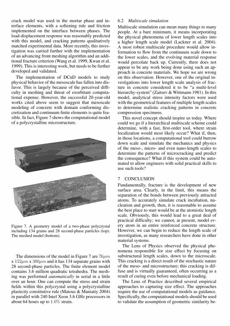
The implementation of DCnD models to studyphysical behavior of the mesoscale has fallen into dis-favor. This is largely because of the perceived diffi-culty in meshing and threat of exorbitant computa-tional expense. However, the successful 20-year-oldworks cited above seem to suggest that mesoscalemodeling of concrete with domain conforming dis-cretization and continuum finite elements is quite fea-sible. In fact, Figure 7 shows the computational modelof a polycrystalline microstructure.
Figure 7. A geometry model of a two-phase polycrystalincluding 134 grains and 28 second-phase particles (top).The meshed model (bottom).
The dimensions of the model in Figure 7 are 76µmx 152µm x 380µm and it has 134 separate grains with28 second-phase particles. The finite element modelcontains 3.6 million quadratic tetrahedra. The mesh-ing was performed automatically in serial in a littleover an hour. One can compute the stress and strainfields within this polycrystal using a polycrystallineplasticity constitutive rule (Matous & Maniatty 2004)in parallel with 240 Intel Xeon 3.6 GHz processors inabout 64 hours up to 1.0% strain.
6.2 Multiscale simulationMultiscale simulation can mean many things to manypeople. At a bare minimum, it means incorporatingthe physical phenomena of lower length scales intoa higher length scale model (Lackner et al. 2004).A most robust multiscale procedure would allow in-formation to flow from the continuum scale down tothe lower scales, and the evolving material responsewould percolate back up. Currently, there does notappear to be any work being done using such an ap-proach in concrete materials. We hope we are wrongon this observation. However, one of the original in-vestigations into lower length scale analysis of frac-ture in concrete considered it to be “a multi-levelhierarchy-system” (Zaitsev & Wittmann 1981). In thismodel, analytical stress intensity factors were usedwith the geometrical features of multiple length scalesto determine realistic cracking patterns in concretecompression specimens.
This novel concept should inspire us today. Wherecould we go if a hierarchical multiscale scheme coulddetermine, with a fast, first-order tool, where strainlocalization would most likely occur? What if, then,in those locations, a computational tool could burrowdown scale and simulate the mechanics and physicsof the meso-, micro- and even nano-length scales todetermine the patterns of microcracking and predictthe consequence? What if this system could be auto-mated to allow engineers with solid practical skills touse such tools?
7 CONCLUSIONFundamentally, fracture is the development of newsurface area. Clearly, in the limit, this means theseparation of the bonds between previously attractedatoms. To accurately simulate crack incubation, nu-cleation and growth, then, it is reasonable to assumethe best place to start would be at the atomistic lengthscale. Obviously, this would lead to a great deal ofpractical difficulty; we cannot, at present, model ev-ery atom in an entire reinforced concrete structure.However, we can begin to reduce the length scale ofinvestigation, as many researchers have done in othermaterial systems.
The Lens of Physics observed the physical phe-nomena responsible for size effect by focusing onsubstructural length scales, down to the microscale.This cracking is a direct result of the stochastic natureof the meso- and microstructure; this cracking is dif-fuse and is virtually guaranteed, often occurring as aresult of curing even before mechanical loading.
The Lens of Practice described several empiricalapproaches to capturing size effect. The approachesrequire the use of computational models as guidance.Specifically, the computational models should be usedto validate the assumption of geometric similarity be-

tween the design structure and the test specimens sup-porting the equations. Also, size effect models ideal-ize all structures as beams or columns and assumestructural analysis is the result of Euler-Bernoullibeam theory; stresses are the result of shears and mo-ments. Currently, the size effect is restricted to bend-ing stress and does not include arbitrary stress in arbi-trary geometry. Furthermore, there is some disagree-ment in the literature as to which of these is the mostfundamentally justifiable. However, it is clear that noempirically-based approach can ever capture the fun-damental physical behavior.
Through the Lens of Dimensionality, it seemspromising that the true nature of the physical phenom-ena known as size effect can be captured and simu-lated using a multiscale approach. Size effect is, af-ter all, a result of strain localization due to distributedmicrocracking. A multiscale framework that explic-itly reproduces the stochasticity of the sub-continuumlength scales, which includes the best known phys-ical models of damage at those length scales, andwhich allows information to flow freely betweenthose length scales would necessarily capture the mi-crocracking process. The skeptic says, “It cannot bedone”. The brave scientist says, “Watch me try”.
This is not to suggest that well developed, under-stood and meaningful empirical formulae that providereliable estimates for design are obsolete. To be sure,they are indispensable. However, 40 years ago whenthe crew of the Star Ship Voyager used their hand-held, portable communicators to talk to anyone in thegalaxy, who would have believed that today every stu-dent roaming a college campus would be carrying awireless telephone? Will we be able to model everyatom in a concrete structure 40 years from now? Def-initely not, if we don’t try.
ACKNOWLEDGMENTSWe humbly acknowledge and thank Professor WalterGerstle for his time and energy. Also, this paper couldnot have been written without the support of the Cor-nell Theory Center.
REFERENCESAtkins, A. G. 1999. Scaling laws for elastoplastic frac-
ture. International Journal of Fracture 95(1), 51–66.
Attinger, S. & Koumoutsakos, P. 2004. Multiscale mod-elling and simulation. Volume 39 of Lecture Notesin Computational Science and Engineering: 51–66.Berlin: Springer.
Bazant, Z. P. 1992. Should design codes consider frac-ture mechanics size effect? In W. Gerstle & Z. P.Bazant (eds), Concrete Design Based on FractureMechanics: 1–24. Detroit: American Concrete In-stitute.
Bazant, Z. P. 1995. Size effect aspects of measurement
of fracture characteristics of quasibrittle material.In F.H. Wittmann (ed), Fracture Mechanics of Con-crete Structures: 1749–1772. Great Britian: Aedifi-catio Publ.
Bazant, Z. P., Murphy, W. P., & Planas, J. 1998. Frac-ture and Size Effect in Concrete and Other Quasib-rittle Materials. CRC Press Inc.
Bazant, Z. P., Tabbara, M. R., Kazemi, M. T., &Pijaudier-Cabot, G. 1990. Random particle modelfor fracture of aggregate or fibre composites.Journal of Engineering Mechanics, ASCE 116(8),1686–1705.
Bazant, Z. P., Yavari, A., Bazant, Z. P., & Yavari,A. 2005. Is the cause of size effect on structuralstrength fractal or energetic-statistical? Engineer-ing Fracture Mechanics 72(1), 1–31.
Carpinteri, A. 1994. Fractal nature of material mi-crostructure and size effects on apparent mechan-ical properties. Mechanics of Materials 18(2), 89–101.
Carpinteri, A., Chiaia, B., & Invernizzi, S. 1999. Three-dimensional fractal analysis of concrete fracture atthe meso-level. Theoretical and Applied FractureMechanics 31(3), 163–172.
Carpinteri, A., Cornetti, P., & Puzzi, S. 2006. Scal-ing laws and multiscale approach in the mechanicsof heterogeneous and disordered materials. AppliedMechanics Reviews 59, 283.
Carpinteri, A. & Ferro, G. 1994. Size effects on tensilefracture properties: a unified explanation based ondisorder and fractality of concrete microstructure.Materials and Structures 27(10), 563–571.
Chang, C. S., Wang, T. K., Sluys, L. J., & van Mier,J. G. M. 2002. Fracture modeling using a micro-structural mechanics approach–ii. finite elementanalysis. Engineering Fracture Mechanics 69(17),1959–1976.
Clough, R. W. 1962. The stress distribution of norforkdam. Technical Report Series 100, Issue 19:Struc-tures and Materials Research, Department of CivilEngineering, University of California, Berkley.
Cusatis, G., Bazant, Z. P., & Cedolin, L. 2003a.Confinement-shear lattice model for concrete dam-age in tension and compression: I. theory. Journalof Engineering Mechanics, ASCE 129(12), 1439–1448.
Cusatis, G., Bazant, Z. P., & Cedolin, L. 2003b.Confinement-shear lattice model for concrete dam-age in tension and compression: Ii. computationand validation. Journal of Engineering Mechanics,ASCE 129(12), 1449–1458.
Cusatis, G., Bazant, Z. P., & Cedolin, L. 2006.Confinement-shear lattice CSL model for fracturepropagation in concrete. Computer methods in ap-plied mechanics and engineering 195(12), 7154–7171.
Ditomasso, A. 1984. Evaluation of concrete fracture. InA. Carpinteri & A. R. Ingraffea (eds), Fracture Me-chanics of Concrete: 137–159. The Hague: Marti-nus Nijhoff Publishers.

Garboczi, E. J. 2002. Three-dimensional mathemati-cal analysis of particle shape using x-ray tomogra-phy and spherical harmonics: Application to aggre-gates used in concrete. Cement and Concrete Re-search 32(10), 1621–1638.
Hafner, S., Eckardt, S., & Konke, C. 2003. A geomet-rical inclusion-matrix model for the finite elementanalysis of concrete at multiple scales. In Proceed-ings of the IKM.
Hafner, S., Eckardt, S., Luther, T., & Konke, C. 2006.Mesoscale modeling of concrete: Geometry and nu-merics. Computers and Structures 84(7), 450–461.
Hillerborg, A. 1989. Fracture mechanics and the con-crete codes. In V. C. Li & Z. P. Bazant (eds), Frac-ture Mechanics: Application to Concrete: 157–169.Detroit: American Concrete Institute.
Hillerborg, A., Modeer, M., & Petersson, P.-E. 1976.Analysis of crack formation and crack growth inconcrete by means of fracture mechanics and finiteelements. Cement and Concrete Research 6, 773–782.
Ingraffea, A., Carter, B., & Wawrzynek, P. 1995. Appli-cation of computational fracture mechanics to re-pair of large concrete structures. In F. H. Wittmann(ed), Concrete Design Based on Fracture Mechan-ics: 1721–1734. Great Britian: Aedificatio Publ.
Kotsovos, M. D. 1979. Fracture processes of concreteunder generalised stress states. Materials and Struc-tures 12(6), 431–437.
Kwan, A. K. H., Wang, Z. M., & Chan, H. C. 1999.Mesoscopic study of concrete ii: nonlinear finiteelement analysis. Computers and Structures 70(5),545–556.
Lackner, R., Mang, H. A., & Pichler, C. 2004. Chap-ter 15: Computational concrete mechanics. Volume2 of Encyclopedia of Computational Mechanics:513–539. John Wiley & Sons, Ltd.
Lilliu, G. & van Mier, J. G. M. 2003. 3d lattice typefracture model for concrete. Engineering FractureMechanics 70(7), 927–941.
Matous, K. & Maniatty, A. 2004. Finite element formu-lation for modelling large deformations in elasto-viscoplastic polycrystals. International Journal forNumerical Methods in Engineering 60(14), 2313–2333.
McDowell, D. L., Gall, K., Horstemeyer, M. F., & Fan.,J. 2003. Microstructure-based fatigue modeling ofcast A356-T6 alloy. Engineering Fracture Mechan-ics 70(1), 49–80.
Ngo, D. & Scordelis, A. C. 1967. Finite element anal-ysis of reinforced concrete beams. Journal of theAmerican Concrete Institute 64(14), 152–163.
Planas, J., Guinea, G., & Elices, M. 1995. Rupture mod-ulus and fracture properties of concrete. In F. H.Wittmann (ed), Concrete Design Based on Frac-ture Mechanics: 95–110. Great Britian: AedificatioPubl.
Planas, J., Guinea, G. V., & Elices, M. 1999. Size effectand inverse analysis in concrete fracture. Interna-tional Journal of Fracture 95(1), 367–378.
Rocco, C., Guinea, G., Planas, J., & Elices, M. 1995.The effect of the boundary condition on the cylindersplitting strength. In F. H. Wittmann (ed), ConcreteDesign Based on Fracture Mechanics: 75–84. GreatBritian: Aedificatio Publ.
Rocco, C., Guinea, G. V., Planas, J., & Elices, M. 1999.Size effect and boundary conditions in the brazil-ian test: theoretical analysis. Materials and Struc-tures 32(6), 437–444.
Roels, S., Sermijn, J., & Carmeliet, J. 2002. Mod-elling unsaturated moisture transport in autoclavedaerated concrete: A microstructural approach.In Building Physics in the Nordic Countries-Proceedings of the 6th symposium: 167–174.
Sadouki, H. & Wittmann, F. H. 1988. On the analy-sis of the failure process in composite materials bynumerical simulation. Materials Science and Engi-neering, A 104, 9–20.
Schlangen, E. 1993. Experimental and numerical anal-ysis of fracture processes in concrete. Ph. D.thesis:Delft University of Technology:Delft, theNetherlands.
Schlangen, E. & Garboczi, E. J. 1996. New method forsimulating fracture using an elastically uniform ran-dom geometry lattice. International Journal of En-gineering Science 34(10), 1131–1144.
Schlangen, E. & Garboczi, E. J. 1997. Fracture sim-ulations of concrete using lattice models: Com-putatoinal aspects. Engineering Fracture Mechan-ics 57(2-3), 319–332.
Slate, F. O. & Hover, K. H. 1984. Microcracking inconcrete. In A. Carpinteri & A. R. Ingraffea (eds),Fracture Mechanics of Concrete: 137–159. TheHague: Martinus Nijhoff Publishers.
Stutzman, P. 2001. Scanning electron microscopy inconcrete petrography. In Materials Science of Con-crete Special Volume: Calcium Hydroxide in Con-crete Proceedings: 59–72.
van Mier, J. G. M. 1997. Fracture Processes of Con-crete. Boca Raton, FL: CRC Press Inc.
van Mier, J. G. M., van Vliet, M. R. A., & Wang, T. K.2002. Fracture mechanisms in particle composites:statistical aspects in lattice type analysis. Mechan-ics of Materials 34(11), 705–724.
Vervuurt, A. & van Mier, J. 1995. Interface fracturein cement-based materials. In F. H. Wittmann (ed),Concrete Design Based on Fracture Mechanics:295–304. Great Britian: Aedificatio Publ.
Wang, Z. M., Kwan, A. K. H., & Chan, H. C. 1999.Mesoscopic study of concrete i: generation of ran-dom aggregate structure and finite element mesh.Computers and Structures 70(5), 533–544.
Wittmann, F. H., Roelfstra, P. E., & Sadouki, H. 1985.Simulation and analysis of composite structures.Materials Science and Engineering 68(2), 239–248.
Zaitsev, Y. B. & Wittmann, F. H. 1981. Simulation ofcrack propagation and failure of concrete. Materialsand Structures 14(5), 357–365.