comparison between induction thermography and … · infrared thermography is an inspection method...
TRANSCRIPT

Comparison between Induction Thermography and Conventional NDT
Methods for Forged Parts
Patrick BOUTEILLE1, Grégory LEGROS
1, Henri WALASZEK
1
1 CETIM, NDT Division, 52 avenue Félix Louat, 60300 Senlis, France
Phone: +33 3 44 67 36 23; e-mail: [email protected]
Abstract
Magnetic particle inspection and dye penetrant inspection are widely used in the industry to inspect metallic
components. These non-destructive testing methods are highly efficient but they induce possible risks for
operators’ health and for environment. So industrialists are looking for an innovative and eco-friendly method
able to keep up the production pace with the same level of detection.
Since several years, CETIM, the French technical center for mechanical industry, has led studies to explore the
possibilities offered by active infrared thermography, and especially induction thermography on forged
components.
In this paper, we will present a comparison between induction thermography and magnetic particle inspection on
a batch of 26 cracked wheels hubs. Destructive metallographic analyses confirm that induction thermography is
able to highlight more defects than magnetic particle inspection, considered yet as the reference method. A
second application of induction thermography will be presented on non-magnetic components. Tests results on
artificial hip joints in titanium, austenitic steel and cobalt-based alloy will be presented in comparison with dye
penetrant results.
Finally, advantages and drawbacks of induction thermography will be discussed compared to those of magnetic
particle inspection and dye penetrant inspection.
Keywords: infrared thermography (IRT), induction, forge, magnetic particle inspection (MPI), dye penetrant
inspection
1. Introduction
The ever stricter requirements issued by customers often result in the need to carry out a
quality inspection on 100% of the parts produced, thus requiring industrialists to implement
increasingly sophisticated non-destructive testing strategies. In order to help industrialists take
up this challenge, CETIM is performing a continuous technological watch on non-destructive
testing techniques under development and contributes to transfer the most promising
techniques to the companies of the mechanical industry.
Infrared thermography is one of those techniques and today it has become the reference
method in many applications such as safety, inspection of electrical installations or inspection
of the thermal insulation of buildings. Infrared thermography has some advantages: it is an
overall method and it has a significant potential for automation. It has already been used
successfully for a few years now for non-destructive testing of materials [1] with rather slow
thermal kinetics (composites, building construction materials, works of art, plastics, etc.).
With the technical developments in faster testing equipment and data processing tools, it is
now possible to contemplate the application of this technique to non-destructive testing of
materials with faster thermal kinetics, such as metallic materials.
2. Active infrared thermography
Infrared thermography is an inspection method widely used in the diagnosis of buildings or
the inspection of electrical cabinets. It consists in using a thermal camera to acquire the heat
flux naturally emitted by the examined body. In this case, this is passive infrared
11th European Conference on Non-Destructive Testing (ECNDT 2014), October 6-10, 2014, Prague, Czech RepublicM
ore
Info
at O
pen
Acc
ess
Dat
abas
e w
ww
.ndt
.net
/?id
=16
516

thermography. The image obtained, called “thermograph”, can therefore reveal an abnormal
variation of the thermal flux and highlight a flaw.
However, in the case of applications in Non-Destructive Testing, production or maintenance,
the parts to be inspected often do not emit heat. By disturbing the analysed sample through
heating and analysing its thermal response, it becomes possible to access data which is not
transmitted spontaneously. This is therefore active infrared thermography. When the parts are
flawed, the analysis of the sequence of images makes it possible to detect heat transfer
discontinuities. It is therefore possible to detect and determine the dimensions of these
discontinuities which correspond to the flaws (delamination, cracks, water infiltration, etc.).
In active infrared thermography, it is necessary to spread a heat flux into the part to be
inspected. This flux can be generated by means of various methods (optical, acoustic or
electrical) or by mechanical deformation. The method used, the position of the heat source
and the heating time will be specifically selected depending on the material to be inspected
and its thickness as well as the nature, position and orientation of the expected flaw.
The temperature rise in the area of a flaw can be generated by various physical principles,
depending on the excitation method used. A thermal barrier is generated by a flaw
perpendicular to the direction of propagation of the heat flux, for example with flash lamps or
halogen lamps for the detection of delamination in composite materials, or with laser scanning
for the detection of cracks open to the surface on metallic materials [2]. In vibrothermography
[3], the goal is to apply a mechanical wave in order to induce vibration at the lips of a crack
and therefore generate a temperature rise in this area. The principle of induction excitation [4]
described Figure 1 is based on an alternating current passing through an excitation coil which
generates induced currents in the electrically conductive object located nearby. These
currents, called “eddy currents”, also generate a temperature rise in the object by Joule effect.
They are disturbed by the presence of a flaw. This anomaly in the distribution of the density
of the induced currents then leads to a concentration of the power density around the flaw
which results in local temperature rises. The temperature distribution inhomogeneity
propagates to the surface of the object and is detected by the infrared camera. All these
different possibilities lead to many ways of implementing the active infrared thermography
method, and each way will answer a particular problem.
Figure 1. Induction thermography principle
In this work, we have associated infrared thermography with eddy current excitation
(induction) to inspect magnetic and non-magnetic forged parts.

3. Forged parts inspection
Forging consists in forming a malleable material by impact or pressing. On the one hand, this
method has the advantage of being performed at a temperature less than the melting
temperature of the material. On the other hand, it makes it possible to form a part while
locally improving its mechanical properties. This is why this method is widely used in the
automobile industry to manufacture ball joints and wheel hubs and in the medical industry to
manufacture prostheses. During the forging process, various defects, such as cold shuts or
cracks can appear on the produced part. For obvious safety reasons, for example in the
automobile and medical industries, it is absolutely necessary to inspect 100% of the parts
produced. Then the inspection methods generally used are magnetic particle inspection for
magnetic materials and dye penetrant inspection for non-magnetic materials.
Magnetic particle inspection and dye penetrant inspection are very efficient and easy-to-use
non-destructive testing methods. They have thus become widely used in the industrial sector.
Unfortunately, they have a few drawbacks. On the one hand, they require the use of cleaning
solvents and aqueous-based or petroleum-based products (red or fluorescent penetrant
products plus developers for dye penetrant inspection, magnetic products for magnetic
particle inspection). These products are not very environmentally-friendly. On the other hand,
the drying, magnetization and demagnetization operations carried out on the parts require
large amounts of energy. Cleaning of parts and removal of the excess penetrant generate a lot
of effluents which will have to be treated. And at last, these two methods have a significant
impact on operators' health. As a matter of fact, operators are exposed to solvent vapors,
organic products and electromagnetic fields. It would be interesting to reduce these
drawbacks or even introduce, in the forging industry, new non-destructive testing methods
which would not have such drawbacks.
The new European Directives aim at reducing the use of energy-intensive, waste-generating
methods potentially hazardous to operators' health. Increasing numbers of industrialists have
become aware of the constraints associated with conventional testing methods and they try to
turn to alternative, more environmentally-friendly methods capable of giving comparable
results. This explains why CETIM has been studying for several years the possibilities of
infrared thermography coupled with induction excitation for non-destructive testing of forged
parts.
The results obtained with induction thermography on steel wheel hubs and on titanium,
stainless steel and cobalt alloy artificial hip joints are presented herein.
4. Inspection of a ferromagnetic steel wheel hub
4.1 Presentation of wheel hubs
The wheel hub is the central section of a wheel attached to the shaft on bushing side, and on
which the rim is installed, on wheel centering side. The wheel hub is a safety component
made of ferromagnetic steel with an outside diameter of 130 mm and a height of
approximately 70 mm.
In the automobile industry, the studied component is submitted to a full magnetic particle
inspection on an automated line. The decision is then made by an operator on line output.
4.2 Testing conditions
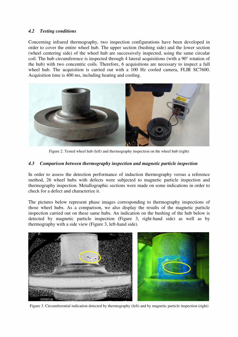
Concerning infrared thermography, two inspection configurations have been developed in
order to cover the entire wheel hub. The upper section (bushing side) and the lower section
(wheel centering side) of the wheel hub are successively inspected, using the same circular
coil. The hub circumference is inspected through 4 lateral acquisitions (with a 90° rotation of
the hub) with two concentric coils. Therefore, 6 acquisitions are necessary to inspect a full
wheel hub. The acquisition is carried out with a 100 Hz cooled camera, FLIR SC7600.
Acquisition time is 400 ms, including heating and cooling.
Figure 2. Tested wheel hub (left) and thermography inspection on the wheel hub (right)
4.3 Comparison between thermography inspection and magnetic particle inspection
In order to assess the detection performance of induction thermography versus a reference
method, 26 wheel hubs with defects were subjected to magnetic particle inspection and
thermography inspection. Metallographic sections were made on some indications in order to
check for a defect and characterize it.
The pictures below represent phase images corresponding to thermography inspections of
those wheel hubs. As a comparison, we also display the results of the magnetic particle
inspection carried out on these same hubs. An indication on the bushing of the hub below is
detected by magnetic particle inspection (Figure 3, right-hand side) as well as by
thermography with a side view (Figure 3, left-hand side).
Figure 3. Circumferential indication detected by thermography (left) and by magnetic particle inspection (right)

A metallographic section made on this indication confirms the presence of a deep cold shut.
Figure 4. Metallographic analysis on the indication detected by thermography and magnetic particle inspection
Figures 5 show a radial defect detected both by infrared thermography (left) and magnetic
particle inspection (right) on wheel centering side.
Figure 5. Radial indication detected by thermography (left) and by magnetic particle inspection (right)
The same coil and the same infrared thermography configuration simultaneously evidenced
the radial and circumferential indications. This is confirmed on the following phase image
obtained during the thermography inspection of a hub with radial and circumferential defects.
The circumferential defect (number 2) is hardly detected by magnetic particle inspection, in
spite of the choice of a testing configuration conducive to its detection.
Figure 6. Inspection on bushing side by thermography (left) and magnetic particle inspection (right)
1
2 1
2

On Figure 7, induction thermography revealed three circumferential indications on bushing
side. The circumferential indication numbered 3 is barely detected by magnetic particle
inspection although it is well detected by induction thermography.
Figure 7. Inspection on bushing side by thermography (left) and by magnetic particle inspection (right)
A metallographic section was made on this indication which was very hardly detected by
magnetic particle inspection. This section confirmed the presence of a cold shut at the
indication detected by thermography (Figure 8).
Figure 8. Metallographic analysis on an indication detected by thermography but not detected by magnetic
particle inspection
4.4 Conclusion on this case
The concentration of eddy currents around the defects reveals very thin defects although the
resolution of the camera is not sufficient to see them in the visible spectrum. Therefore, on the
hubs, the indications seem to have a width of approximately one millimeter whereas the
opening of the defect is only of a few microns. Thermography allows defects to be detected in
1
3
1
2
2
3
both directions (radial and circumferential) even if the chosen configuration is better suited
for radial defects.
Over the 26 wheel hubs with defects subjected to infrared thermography and magnetic
particle inspection, thermography revealed more indications than magnetic particle inspection
which is yet considered as a reference method in the industrial sector. The metallographic
analyses carried out on approximately twenty indications confirmed the presence of a defect
for each detected indication.
In order to cover the entire hub, 6 acquisitions are necessary, with rotation or the turning over
of the part. An automated inspection method would allow each hub to be inspected within a
few seconds. It can provide an inspection rate similar to that of the current industrial magnetic
particle inspection process.
Obtaining digital images also allows the sanction to be automated: it allows computer-aided
detection of indications on images obtained by thermography. This step would make it
possible to reduce the manpower necessary for the inspection and, thereby, to reduce the costs
of the inspection.
Therefore, infrared thermography coupled with induction excitation is a credible alternative
for the replacement of magnetic particle inspection on this type of forged parts.
5. Inspection of an artificial hip joint made of non-magnetic material
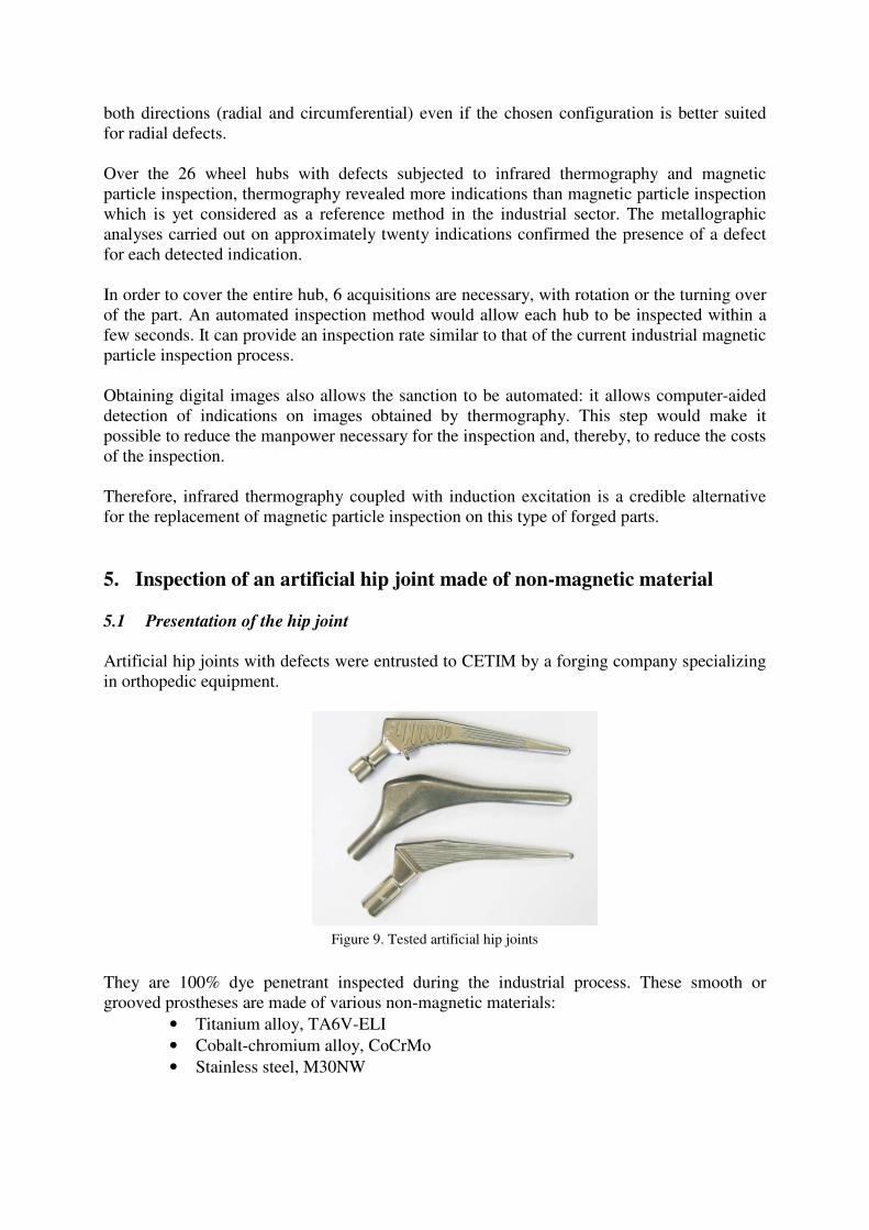
5.1 Presentation of the hip joint
Artificial hip joints with defects were entrusted to CETIM by a forging company specializing
in orthopedic equipment.
Figure 9. Tested artificial hip joints
They are 100% dye penetrant inspected during the industrial process. These smooth or
grooved prostheses are made of various non-magnetic materials:
• Titanium alloy, TA6V-ELI
• Cobalt-chromium alloy, CoCrMo
• Stainless steel, M30NW

5.2 Testing conditions
As the tested prostheses were made of non-ferromagnetic materials, induction heating was
less efficient for infrared thermography inspection on these parts compared to ferromagnetic
parts. As a matter of fact, the depth of the eddy currents is more significant on these materials.
The tested inductors are composed of two Helmholtz coils, i.e. two circular coils with the
same radius, parallel to each other and located opposite each other and at a distance equal to
the coil radius. Electrical current is circulated in these coils and the magnetic field created in
their vicinity is relatively uniform at the center of the system. Acquisition is carried out with a
100 Hz cooled camera, FLIR SC7600.
5.3 Comparison between thermography testing and penetrant testing
Infrared thermography is assessed through tests carried out on 15 artificial hip joints and
comparison with the results obtained with penetrant testing. Figures 10 show a phase image
corresponding to the thermography testing (left) of a smooth stainless steel prosthesis and the
result of the penetrant testing (right) carried out on this same prosthesis.
Figure 10. Inspection of a stainless steel hip joint by thermography testing (left) and penetrant testing (right)
The figures below show the comparison between thermography testing and penetrant testing
in order to detect a defect on the smooth portion of a cobalt-chromium alloy prosthesis.
Figure 11. Inspection of a cobalt-chromium alloy prosthesis by thermography (left) and penetrant testing (right)

Forging defects located inside a groove on titanium prostheses aren’t detected by this
thermography configuration, although they are detected by penetrant testing (Figure 12).
Figure 12. Inspection of a titanium prosthesis by penetrant testing
The position of the defect (at the bottom of a groove) or its depth, are certainly the reasons
why it was not detected. In fact, detecting defects on titanium parts is possible. In particular,
this is the case in the example below (Figure 13) on a titanium plate with defects created
artificially by forging.
Figure 13. Inspection of a titanium plate by thermography testing
5.4 Conclusion on this case
Induction excitation is well suited to ferromagnetic materials, but it is less efficient at heating
titanium, stainless steel or cobalt-based alloy. At equal frequency, the depth of the eddy
currents generated by induction is more important on these materials than on ferromagnetic
materials.
However, these tests prove that infrared thermography coupled with induction excitation
reveals a great part of the defects found during penetrant testing. On the artificial hip joints,
only the defects located in the grooves are not detected by infrared thermography. The defects
located on a smooth area of the prosthesis, invisible with the naked eye, are well detected.
6. Conclusions and perspectives
Through its various studies [5, 6, 7, 8, 9], CETIM is trying to better determine the limits of
infrared thermography for detecting surface defects on metallic materials.
In this document, we have proven that induction thermography is a potential alternative for
the replacement of magnetic particle inspection on magnetic forged parts such as wheel hubs.
In fact, in this case, thermography enables to obtain the same detection quality as
conventional testing methods. The testing rate is similar, with an inspection of a few seconds
after automation. Automatic sanction, i.e. automatic detection of defects without human
intervention, which is very difficult with magnetic particle testing, is possible with
thermography testing thanks to the digital images provided by cameras. This represents a
significant reduction of inspection costs. Thermography is also an environment-friendly,
energy-efficient method which does not require the use of any chemical. Finally,
thermography reduces risks for personnel's health as it complies with European directives
regarding operators' exposure to electromagnetic fields and solvent vapors.
We have also demonstrated that induction thermography reveals forging defects on non-
magnetic materials. Comparisons with penetrant testing on hip joints are satisfactory. Eddy
current generation at higher frequencies would enable the limitation of the current penetration
depth and possibly improve detection. Future works will consist in performing metallographic
sections at the detected defects in order to assess their depth and opening. It would enable to
draw conclusions on the performance and limits of thermography for non-magnetic materials.
References
1. Maldague X., “Introduction to NDT by active infrared thermography”, Materials
Evaluation, Vol. 6, No 9, pp. 1060 -1073, 2002
2. Bodnar J.L., Edée M., Menu C., Besnard R., Le Blanc A., Pigeon M., Sellier J.Y.,
“Cracks detection by a moving photothermal probe”, Journal de Physique IV, C7-592,
1994
3. Zweschper Th., Dillenz A., Riegert G., Scherling D., Busse G., “Ultrasound excited
thermography using frequency modulated elastic waves”, Insight, Vol. 45, No 3, 2003
4. Vrana J., Goldammer M., Baumann J., Rothenfusser M., Arnold W., “Mechanisms and
Models for Crack Detection with Induction Thermography”, Review of Progress in
QNDE 27, pp. 475-482, 2008
5. Maillard S., Cadith J., Eschimese D., Walaszek H, Mooshofer H., Candore J. C., Bodnar
J.L., “Towards the use of passive and active infrared thermography to inspect metallic
components in the mechanical industry”, QIRT congress proceedings, Laval (Quebec),
2010
6. Maillard S., Cadith J., Walaszek H., Bodnar J.L., “Active infrared thermography and its
new applications to metallic materials”, COFREND congress proceedings, Dunkerque
(France), 2011
7. Bouteille P., Legros G., Maillard S., Cadith J., Bodnar J.L., “Induction active
thermography as an alternative to magnetic particle inspection”, QIRT congress
proceeding, Naples (Italy), 2012
8. Bouteille P., Legros G., “Induction thermography: an alternative to conventional NDT on
forged components”, COFREND congress proceedings, Bordeaux (France), 2014
9. Bouteille P., Legros G., “Induction thermography as an alternative to conventional NDT
methods for forged parts”, QIRT congress proceeding, Bordeaux (France), 2014