comparative study into occupant support concepts …
TRANSCRIPT

UUnniivveerrssiittyy ooff PPrreettoorriiaa eettdd –– MMeeiinnttjjeess,, SS WW vv dd MM ((22000044))
COMPARATIVE STUDY INTO OCCUPANT SUPPORT CONCEPTS WITH RESPECT TO
CRASH RESPONSE
SCHALK WILLEM VAN DER MERWE MEINTJES
A dissertation submitted in partial fulfilment of the requirements for the degree of
MASTER OF ENGINEERING (AERONAUTICAL ENGINEERING)
In the
FACULTY OF ENGINEERING
UNIVERSITY OF PRETORIA
October 2003

UUnniivveerrssiittyy ooff PPrreettoorriiaa eettdd –– MMeeiinnttjjeess,, SS WW vv dd MM ((22000044))
Comparative Study into Occupant Support Concepts with Respect to
Crash Response
By: S W vd M Meintjes
Supervisor: Prof N J Theron
Co-Supervisor: Mr R J Huyssen
Department: Mechanical and Aeronautical Engineering
University: University of Pretoria
Degree: Master of Engineering (Aeronautical Engineering)
ABSTRACT
It is argued that together with improved protection structures and energy dissipation systems, a favourable
pilot position with sufficient support and restraint could reduce fatalities in aviation accidents. In this
document the crash response of three different pilot positions are compared to justify the proposal of
supporting a pilot in the rather unusual prone position.
The normal seated and supine pilot positions have already been adopted and implemented in various
aircraft. The occupant’s response to specified crash scenarios in these two positions was compared to that
of a pilot in the prone position. To obtain the best prone pilot support configuration, different concepts
were considered during the analysis. A dynamic event simulation program called ADAMS was used to
perform the analysis and existing injury criteria and a study of common causes of aviation fatalities and
human body tolerance limits were used to compare the results.
Additionally, methods to improve survivability of a pilot in the prone position during likely accidents were
investigated with ADAMS. Concepts for the Exulans fuselage layout and energy absorption systems were
proposed and recommendations for the pilot support system were derived from the results.

UUnniivveerrssiittyy ooff PPrreettoorriiaa eettdd –– MMeeiinnttjjeess,, SS WW vv dd MM ((22000044))
Comparative Study into Occupant Support Concepts with Respect to
Crash Response
Deur: S W vd M Meintjes
Studieleier: Prof N J Theron
Mede studieleier: Mnr R J Huyssen
Departement: Meganiese en Lugvaartkundige Ingenieurswese
Universiteit: Universiteit van Pretoria
Graad: Magister (Lugvaartkundige Ingenieurswese)
SAMEVATTING
Dit word geargumenteer dat lewensverlies tydens lugvaartongelukke verminder kan word deur ‘n geskikte
liggaamsposisie met voldoende ondersteuning en beperking in kombinasie met verbeterde strukture en
energie absorberende materiale en meganismes, te implimenteer. Met hierdie dokument word die
impakreaksie van drie verskillende ligaamsposisies vergelyk, om sodoende die voorstel om die vlieënier in
die ietwat ongewone vooroorlêhouding te ondersteun, te staaf.
Die regop sittende en agteroor sittende vlieëniers posisies is alreeds aanvaar en kom algemeen in verskeie
vliegtuie voor. Die vlieënier se reaksie op verskillende impak situasies in hierdie twee posisies was
vergelyk met die van ‘n vlieënier in die vooroorlêhouding. Om te verseker dat die beste vooroorlêhouding
konsep gebruik word, was verskeie konfigurasies van hierdie posisie oorweeg tydens die analiese. Die
rekenaar program genaamd “ADAMS”, wat die dinamika van enige meganiese stelsel simuleer, was
gebruik om die analieses mee te doen. Bestaande beseringskriteria en ‘n studie van algemene oorsake van
lewensverlies tydens lugvaart ongelukke en liggaamsimpaktoleransielimiete was gebruik om die resultate te
vergelyk.
Addisioneel was metodes om die oorleefbaarheid van ‘n vlieënier in die vooroorlêhouding tydens
waarskynlike vliegtuigongelukke te verbeter ook ondersoek met “ADAMS”. Konsepte vir die uitleg van
Exulans II se rompstruktuur en energieabsorberendesisteme asook aanbevelings vir die vlieënier se
ondersteuningssisteem, was afgelei vanuit die resultate.

UUnniivveerrssiittyy ooff PPrreettoorriiaa eettdd –– MMeeiinnttjjeess,, SS WW vv dd MM ((22000044))
ACKNOWLEDGEMENTS
I wish to express my gratitude to the following organisations and persons who made this dissertation
possible:
a) Armscor and Land Mobility Technologies for the provision of data during the course of the study.
b) The following persons are gratefully acknowledged for their assistance during the course of the
study:
i) Robert Cathro
ii) Andy Hodgsen
iii) Elton Murison
iv) Jaco Nolte
v) Klaus Schwerdtfeger
vi) Clinton Stone
c) Professor N J Theron my supervisor, and Mr R J Huyssen, my co-supervisor for their guidance
and support.
d) My parents for their encouragement and support during the study.
e) My God for granting me the ability and opportunity to complete this study.

UUnniivveerrssiittyy ooff PPrreettoorriiaa eettdd –– MMeeiinnttjjeess,, SS WW vv dd MM ((22000044))
TABLE OF CONTENTS
LIST OF TABLES vi
LIST OF FIGURES vi
NOMENCLATURE x
CHAPTER 1: INTRODUCTION 1
1.1 Project Background 2
1.2 Thesis Overview 2
1.3 Document Layout 3
CHAPTER 2: LITERATURE SURVEY 4
2.1 Introduction 5
2.2 Causes of Aviation Fatalities 6
2.3 Human Impact Tolerance Limits 7
2.4 Crash Survivability 11
2.5 Crash Survival Design Considerations 12
2.6 Impact Injury Criteria 15
2.7 Crash Pulse Shapes 20
2.8 Dynamic Crashworthiness Testing 23
2.9 Pilot Support Positions 25
2.10 Summary 35
CHAPTER 3: PROPOSED CONCEPTS 37
3.1 Thesis Specifications 38
3.2 Proposed Pilot support Position 39
3.3 Reasons Leading to the Pilot Support Proposal 41
3.4 CREEP Concept Design Proposals 43
3.4.1 Container Concept 43
3.4.2 Restraint Concept 44
3.4.3 Energy Absorption Concept 45
3.4.4 Environment Considerations 46
3.4.5 Post-Crash Factors 46
3.5 Conclusion 47

UUnniivveerrssiittyy ooff PPrreettoorriiaa eettdd –– MMeeiinnttjjeess,, SS WW vv dd MM ((22000044))
CHAPTER 4: DYNAMIC ANALYSIS 48
4.1 The Approach 49
4.2 The Analysis Tools 49
4.3 Meet The Pilots 50
4.4 Validation and Verification 52
4.5 Sled Impact Tests 59
4.5.1 Normal Seated Position 64
4.5.2 Prone Pilot Position 65
4.5.3 Supine Seated Position 67
4.5.4 Sled Test Results 67
4.5.5 Conclusion 74
4.6 Fuselage Crash Tests 75
4.6.1 Crash Scenarios 75
4.6.2 The Analysis 77
4.6.3 Crash Test Results 81
4.6.4 Conclusion 82
CHAPTER 5: FINAL CONCLUSION AND RECOMMENDATIONS 83
REFERENCES 87
APPENDIX A THE HYBRID III CRASH TEST DUMMY 91
APPENDIX B SHOULDER HARNESS AND SAFETY BELT INSTALLATIONS 97
APPENDIX C JOINT AVIATION REGULATIONS SELECTIONS 108
APPENDIX D ADAMS AND FIGURE HUMAN MODELLER 117
APPENDIX E ADDITIONAL RESULTS 123
APPENDIX F COMPACT DISC 133

UUnniivveerrssiittyy ooff PPrreettoorriiaa eettdd –– MMeeiinnttjjeess,, SS WW vv dd MM ((22000044))
LIST OF TABLES
2.1 Accelerations known to cause bone fracture and concussion 10
2.2 Critical intercepts for neck injury criteria 18
4.1 Validation injury criteria comparison 56
4.2 Sled test injury criteria results 74
4.3 Fuselage crash tests injury criteria results 82
A1 Comparison of weight 94
A2 Segmented weights 94
A3 Dimensions 94
A4 Instrumentation 95
E1 Calculation of neck injury criteria 131
E2 Injury criteria results 132
E3 Impact force on mandible of prone positioned pilot 132
LIST OF FIGURES
2.1 Energy absorbing crew seat used in the V-22 aircraft 5
2.2 Typical impact acceleration pulse shape 8
2.3 Aircraft axis convention 9
2.4 Acceleration axes for imaginary eyeball terminology 9
2.5 Acceptable range of neck loading modes for the Hybrid III mid-sized male 18
2.6 Rectangular acceleration pulse shape 21
2.7 Increasing acceleration pulse shape 21
2.8 Decreasing acceleration pulse shape 22
2.9 Increasing decreasing acceleration pulse shape 22
2.10 FAR 23.562 dynamic Test 1 24
2.11 FAR 23.562 dynamic Test 2 24
2.12 Aviator in the normal seated position 26
2.13 Three-point restraint 26
2.14 Four and five-point restraint 27
2.15 Historic flight by Orville Wright on 17 December 1903, note the prone position 28
2.16 Hang glider with pilot in prone position 29
2.17 The Berlin B-9 prone pilot aircraft 29
2.18 The Horten Ho IV flying wing with the pilot in the prone position 30

UUnniivveerrssiittyy ooff PPrreettoorriiaa eettdd –– MMeeiinnttjjeess,, SS WW vv dd MM ((22000044))
2.19 A close-up of the Ho IV showing the prone pilot position 30
2.20 The MasterBlaster aerobatics aircraft concept with prone pilot 31
2.21 Exulans II glider with prone pilot 31
2.22 The rider of a super bike in the riding position 32
2.23 Gloster Meteor F8 prone pilot experimental aircraft 33
2.24 The supine position used in sailplanes 34
2.25 Recommended lap and shoulder belt attachment point in supine position 35
3.1 Prone pilot position ergonomical investigation 40
3.2 Steel frame mock-up 40
3.3 Direction of impact load on prone pilot during likely crash scenario 41
3.4 High angle of attack landing executed in different pilot positions 42
3.5 Exulans II container concept 43
3.6 Pilot wearing the custom manufactured harness 44
3.7 Collapsible landing skid mechanism 45
4.1 The normal seated pilot in the normal seated position 51
4.2 The prone pilot in the prone position 51
4.3 The supine seated pilot in the supine position 51
4.4 Vertical impact experiment with Hybrid III ATD 52
4.5 ADAMS model of vertical impact experiment 53
4.6 Lumbar spine force comparison 54
4.7 Head acceleration magnitude comparison 54
4.8 Lumbar spine force peak comparison 55
4.9 Head acceleration magnitude peak comparison 55
4.10 Static seat characterisation experimental test set-up 56
4.11 Artificial buttock with typical seat cushion 57
4.12 Seat stiffness data obtained from static test 57
4.13 ADAMS model of seat characterisation experiment 58
4.14 Experimental and ADAMS seat stiffness data 58
4.15 Test 1 model with translation constraints and applied crash pulse vector 59
4.16 Test 2 model with translation constraints and applied crash pulse vector 60
4.17 Webbing stiffness curves 61
4.18 Modelling belt slack and belt pretension with the ADAMS spline function 61
4.19 Pulse shape calculation for Test 1 62
4.20 Pulse shape calculation for Test 2 63
4.21 Test sled with normal seated configuration 64

UUnniivveerrssiittyy ooff PPrreettoorriiaa eettdd –– MMeeiinnttjjeess,, SS WW vv dd MM ((22000044))
4.22 Test sled with prone restraint concept 1 65
4.23 Test sled with prone restraint concept 2 66
4.24 Test sled with prone restraint concept 3 66
4.25 Test sled with supine seated configuration 67
4.26 Dynamic Test 1: lumbar spine force results calculated by ADAMS 68
with grey acceleration pulse scaled to right vertical axis
4.27 Dynamic Test 1: head acceleration magnitude results calculated by ADAMS 69
with grey acceleration pulse shape on scale
4.28 Dynamic Test 1: flailing envelopes calculated by ADAMS 70
4.29 Dynamic Test 2: lumbar spine force results calculated by ADAMS 72
with grey acceleration pulse scaled to right vertical axis
4.30 Dynamic Test 2: head acceleration magnitude results calculated by ADAMS 72
with grey acceleration pulse on scale
4.31 Dynamic Test 2: flailing envelopes calculated by ADAMS 73
4.32 Fuselage crash test cage with pilots in different positions 78
4.33 Airframe impact attitude of Crash Scenario 1 79
4.34 Airframe impact attitude of Crash Scenario 2 80
4.35 Airframe impact attitude of Crash Scenario 3 80
A1 The Hybrid III crash test dummy family 91
A2 Hybrid III neck sensors 92
A3 Steel ribs with measuring equipment in upper torso 93
A4 ATD axes definition 96
B1 Single strap 3-point restraint 98
B2 Dual strap 4-point restraint 98
B3 Dual strap 5-point restraint 98
B4 Acceptable lap belt attachment angles 101
B5 Incorrect shallow and steep belt angles 102
B6 Correct and incorrect single diagonal shoulder harness attachment 102
B7 Incorrect upper shoulder harness attachments 103
B8 Typical concepts for dual shoulder harness installations 104
B9 Incorrect and correct shoulder harness safety belt installations 104
B10 Installation of the negative-G strap 104
B11 Acceptable range of upper attachment points 105
B12 Compression of spine due to incorrect shoulder strap installation 106
B13 Spinal compression due to resultant restraint force 106

UUnniivveerrssiittyy ooff PPrreettoorriiaa eettdd –– MMeeiinnttjjeess,, SS WW vv dd MM ((22000044))
C1 Lap and shoulder belt attachment points in supine position 109
D1 ADAMS Impact function force exponent ranges 119
D2 ADAMS Impact function penetration depth and damping step function 119
D3 Human models displayed as ellipsoids, skeletal or a skin clothed model 120
D4 Typical active simulation with FIGURE 121
E1 Validation seat rig input displacement 123
E2 Test 1 prone concepts lumbar load comparison 124
E3 Test 1 prone concepts head acceleration comparison 124
E4 Test 2 prone concepts lumbar load comparison 125
E5 Test 2 prone concepts head acceleration comparison 125
E6 Test 1 neck axial loads and bending moments 126
E7 Test 2 neck axial loads and bending moments 127
E8 Crash 1 neck axial loads and bending moments 128
E9 Crash 2 neck axial loads and bending moments 129
E10 Crash 3 neck axial loads and bending moments 130

UUnniivveerrssiittyy ooff PPrreettoorriiaa eettdd –– MMeeiinnttjjeess,, SS WW vv dd MM ((22000044))
NOMENCLATURE
Symbols
g Gravitational Acceleration (9.81m/s2)
Gm Maximum acceleration as a multiple of g
Gx Acceleration in x direction as a multiple of g
Gy Acceleration in y direction as a multiple of g
Gz Acceleration in z direction as a multiple of g
t Time (seconds)
tm Time at maximum acceleration or rise time (seconds)
V0 Initial Velocity (m/s)
Vf Final Velocity (m/s)
∆V Velocity Change (m/s)
Abbreviations
ADAMS Automatic Dynamic Analysis of Mechanical Systems
ATD Anthropomorphic Test Dummy
CAD Computer Aided Drawing
CFIT Controlled Flight Into Terrain
CFR Code of Federal Regulations
CG Centre of Gravity
DRI Dynamic Response Index
FAA Federal Aviation Administration
FAR Federal Aviation Regulations
FMVSS Federal Motor Vehicle Safety Standard
HANS Head and Neck Support
HIC Head Index Criteria
JAR Joint Aviation Regulations
LLC Lumbar Load Criteria
LMT Land Mobility Technologies
NHTSA National Highway Traffic Safety Administration
TSO Technical Standard Order
3D Three Dimensional

UUnniivveerrssiittyy ooff PPrreettoorriiaa eettdd –– MMeeiinnttjjeess,, SS WW vv dd MM ((22000044))
CHAPTER 1: INTRODUCTION
Preview
1. In this chapter the reader is introduced to the Exulans project and some background on the thesis
are provided.
2. The motivation behind the thesis and the actions to be expected during the course of this document
is summarised in the thesis overview.
3. The chapter is concluded with an overview of the layout of this document.

UUnniivveerrssiittyy ooff PPrreettoorriiaa eettdd –– MMeeiinnttjjeess,, SS WW vv dd MM ((22000044))
1.1 Project Background
The Department of Mechanical and Aeronautical Engineering at the University of Pretoria has undertaken a
project in which a new aircraft is being developed. In this project various shortcomings of current aviation
practice are being investigated. One of the shortcomings relates to occupant protection during survivable
mishaps and it is argued that many aviation fatalities could be avoided through better design. This thesis
forms a central part in the ambition of improving occupant protection in light aircraft and also proposes a
pilot protection system for the Exulans glider.
Exulans is a high performance ultra-light glider under development at the University of Pretoria. It is
unique in the fact that it has no tail and that it utilises the concept of variable outer wing sweep to perform
certain aerodynamical tasks. The tailless gull-wing configuration was copied from the Albatross and initial
tests with the first prototype indicated that this configuration proofed to possess great potential for tailless
flight and short field take-off and landing.
In the Exulans project the challenge of pilot protection is addressed from two sides, the aerodynamic side
and the structural/systems side. The challenge of this thesis, however, was to look at pilot protection from a
structural and ergonomical point of view during a crash or bad landing. Pilot protection during an impact
event is essentially an energy management task that requires the absorption or deflection of crash energy
away from the occupant.
1.2 Thesis Overview
Generally speaking, aviation is considered dangerous because of the huge amount of energy involved in
flight. The challenge of pilot protection, however, arises in the management of the energy at the end of the
flight. The potential energy component of an aircraft is dissipated into the atmosphere during the descent
and in special cases a portion of the kinetic energy can also be dissipated prior to the landing.
The tailless aerodynamic layout of Exulans allows the execution of a high angle of attack or “flared”
landing. During this action the angle of attack of the glider is suddenly increased to allow the wing to act as
a massive airbrake. This action releases some of the kinetic energy into the atmosphere but still leaves the
glider with enough energy that could injure or kill the pilot during a mishap.

UUnniivveerrssiittyy ooff PPrreettoorriiaa eettdd –– MMeeiinnttjjeess,, SS WW vv dd MM ((22000044))
It was suspected that higher crash survivability could be obtained with a pilot supported in the prone
position. This suspicion and several other reasons led to the suggestion of supporting the pilot in the prone
position within the Exulans cockpit. To verify this suggestion, the crash survivability in this position was
investigated by comparing the crash response of a pilot supported in the prone position with those
supported in conventional flying positions. The positions selected for the comparison were the normal
seated position adopted by most powered aircraft and the supine seated position found in many sailplane
designs.
The three positions were subjected to common crash scenarios using a mechanical system simulation
software package called ADAMS. This program simulates dynamic events by setting up and solving the
equations of motion for the system and is also equipped with a virtual Hybrid III crash dummy to simulate
human response to impact. By using impact injury criteria and investigating frequent aviation fatalities and
human body tolerance limits the results of the three different positions were compared to each other.
1.3 Document Layout
In this document Chapter 1 serves as an introduction and also contains some background to the thesis. The
summary of the literature study is contained in Chapter 2 and is followed by Chapter 3, which states the
thesis specifications and concept proposals. The technical detail and results of the dynamic analysis are
contained in Chapter 4. The final conclusions and recommendations are made in Chapter 5 and a list of
references is included at the end of the report.
Information on the Hybrid III crash test dummy used to evaluate human response to impact was included in
Appendix A while guidelines and recommendations on restraining aircraft occupants were submitted as
Appendix B. Some of the relevant Joint Aviation Regulations were summarised in Appendix C and the
capabilities of ADAMS and FIGURE Human Modeller are described in Appendix D. Appendix E contains
additional results of the dynamic analysis and a layout of the contents of the compact disk is included as
Appendix F.

UUnniivveerrssiittyy ooff PPrreettoorriiaa eettdd –– MMeeiinnttjjeess,, SS WW vv dd MM ((22000044))
CHAPTER 2: LITERATURE SURVEY
Preview
1. To familiarise ourselves with historical studies on the topic of occupant protection in aircraft a
literature study was launched.
2. This chapter summarises the results of the literature survey. Topics that were investigated during this
phase include:
Similar studies on the topic of occupant protection in aircraft
The major causes of aviation fatalities
Human impact tolerance limits
Crash survivability and crash survival design considerations
The criteria for impact injury
Crash pulse shapes
The requirements for dynamic crashworthiness testing
Different pilot support positions
3. A summary and some remarks on the literature study conclude this chapter.

UUnniivveerrssiittyy ooff PPrreettoorriiaa eettdd –– MMeeiinnttjjeess,, SS WW vv dd MM ((22000044))
2.1 Introduction
Amongst several studies on the topic of occupant protection during aircraft accidents, Winkelman &
Laananen (1996) reported that the U.S Army conducted crash testing and accident analyses, which led to
the establishment of crashworthy requirements for Army rotorcraft and small fixed wing aircraft. The U.S
Military’s SH-60 B Sea Hawk, UH-60 A Black Hawk and AH-64 A Apache helicopters have been
designed in accordance with the crashworthy requirements and have been equipped with energy-absorbing
crew seats.
According to Labun & Rapaport (1994) the energy-absorbing crew seat design featured a moveable seat
bucket attached to the aircraft structure through an energy absorber (Figure 2.1), which displace or “stroke”
towards the helicopter floor to absorb some of the energy during a high impact event. Much of the work in
the past was however, predominantly focused on protection of normal seated pilots where the main
objective of the EA seat was to prevent spinal injury to the aviator in this position. (Rapaport, Yeiser &
Oslon 1995; Richards & Podop 1997).
Figure 2.1: Energy absorbing crew seat used in the V-22 aircraft (Rapaport, Yeiser & Oslon 1995)

UUnniivveerrssiittyy ooff PPrreettoorriiaa eettdd –– MMeeiinnttjjeess,, SS WW vv dd MM ((22000044))
2.2 Causes of Aviation Fatalities
The major causes of aviation fatalities are classified into four categories. According to The Naval Flight
Surgeon’s Pocket Reference to Aircraft Mishap Investigation (1995), the four major injury types associated
with aviation accidents include the following:
Thermal
Thermal injury is the cause of 50% of all aviation fatalities and involves burning and smoke inhalation.
Intrusive
Intrusive injuries occur when the living or occupiable space is lost due to penetration of the container.
Cases that have occurred are decapitation by electrical wires or fences, body penetrations by sticks, push
rods, fractured structural pieces etc. These type of injury leads to excessive bleeding and/or organ damage.
Impact
Impact injury involves impact of the body into an object or visa versa or impact into the belts of the
restraint system. Reported cases include impact into the control stick and restraint system causing organ
damage and/or lacerations. Head injury, responsible for a third of all aviation fatalities, often occur due to
head impact into the instrument panel and can lead to concussion or skull fracture (The Naval Flight
Surgeon’s Pocket Reference to Aircraft Mishap Investigation 1995) Dynamic overshoot can occur when the
head gains a greater relative velocity than the surrounding cabin and would result in an impact force
exceeding that of the actual crash force.
It could further be argued that head injury or any other injury for that matter, sustained during the dynamic
portion of the crash, would contribute to thermal aviation fatalities. An occupant surviving the impact could
die due to thermal injury if he was left unconscious in the burning wreckage due to a head injury sustained
during the crash.

UUnniivveerrssiittyy ooff PPrreettoorriiaa eettdd –– MMeeiinnttjjeess,, SS WW vv dd MM ((22000044))
Decelerative
The organs of the human body are very sensitive to high accelerations. The following injuries have
occurred as a result of high deceleration.
• Fracture dislocation of the neck (C1 on C2) 20 – 40g
• Concussion 60g over 0.02 seconds
100g over 0.005 seconds
• Aorta transection 80 – 100g
• Pelvic fracture 100 – 200g
• Vertebral body transection 200 – 300g
• Total body fragmentation 350g
2.3 Human Impact Tolerance Limits
The name Colonel John Paul Stapp is synonymous with body tolerance limit studies. According to the
History of Research in Space Biology and Biodynamics (1985) and Cavanaugh (2000), Col. Stapp
conducted rocket sled acceleration tests in the 1950’s, which provided most of the data on human tolerance
to high magnitude deceleration. High magnitude deceleration is classified as deceleration exceeding 10g
and lasts for less than one second. According to the Advisory Circular (1985), further body tolerance limits
resulted from tests with voluntary human subjects who were exposed to increasingly severe impacts whilst
being held by a specific seat and restraint system. The level of the impacts was increased until a subject felt
that further tests would be unbearable.
With modern technology, the use of the Anthropomorphic Test Dummy (ATD) and computer simulation
programs became more appropriate in determining the response of humans to high magnitude
decelerations. The ATD is a dummy used in place of a human to evaluate crash impact protection systems
by simulating human response in dynamic events. It was designed to resemble the mass and dimensions
and the kinematic behaviour of the prominent joints and ligaments in the human body. More information on
the Hybrid III ATD is contained in Appendix A.

UUnniivveerrssiittyy ooff PPrreettoorriiaa eettdd –– MMeeiinnttjjeess,, SS WW vv dd MM ((22000044))
The Naval Flight Surgeon’s Pocket Reference to Aircraft Mishap Investigation (1995) states that human
tolerance to acceleration is a function of the following aspect (see also Figure 2.2).
• The acceleration pulse shape and the initial acceleration slope (rate of onset in g/second)
• The acceleration direction with respect to the body
• The acceleration duration or the time interval from initial impact velocity to zero velocity
• The acceleration magnitude (peak g)
• The type of seat and restraint
• The physical characteristics of the aviator
• Secondary impact of body into subjects
• The distribution of force over the body
Figure 2.2: Typical impact acceleration pulse shape
It is difficult or rather impossible to isolate each of these factors, but it is known that the longer the
duration, the greater the magnitude, or the higher the rate of onset, the less likely a person is to survive.

UUnniivveerrssiittyy ooff PPrreettoorriiaa eettdd –– MMeeiinnttjjeess,, SS WW vv dd MM ((22000044))
The crash forces and accelerations experienced by the airframe and occupants in an accident is a three
dimensional event along the three axes. Normally the aircraft’s axes are referred to as X, forward and
parallel to the fuselage, Y to the right and parallel to the wing and Z downwards as shown in Figure 2.3.
Figure 2.3: Aircraft axis convention (McCormick 1979: 478)
The co-ordinate system used to describe forces and accelerations on the occupant will however differ from
the above in the sense that positive Z will be upward and positive Y will be to the left as indicated in Figure
2.4. As described by Wood & Sweginnes (1996), a discussion of accelerations acting on the human body in
these three directions can get confusing, therefore an imaginary eyeball movement terminology has been
adopted. The terminology states that a chest to back acceleration (-Gx) e.g. aircraft carrier landing will
cause an eyeballs-out scenario. An ejection seat will cause an eyeballs-down acceleration (+Gz) while
sideways acceleration will cause eyeballs-left or eyeballs-right scenarios as indicated in Figure 2.4.
Figure 2.4: Acceleration axes for imaginary eyeball terminology (Wood & Sweginnes 1996)

UUnniivveerrssiittyy ooff PPrreettoorriiaa eettdd –– MMeeiinnttjjeess,, SS WW vv dd MM ((22000044))
The following limits are realistic for a properly restraint occupant for duration and rate of onset found in
most survivable mishaps (The Naval Flight Surgeon’s Pocket Reference to Aircraft Mishap Investigation
1995)
• +Gz (eyeballs-down) 25g over 0.1 seconds
• -Gz (eyeballs-up) 15g over 0.1 seconds
• +Gx (eyeballs-in) 45g over 0.1 seconds
• -Gx (eyeballs-out) 45g over 0.1 seconds
• +Gy (eyeballs-right) 11.5g - 20g over 0.1 seconds
• -Gy (eyeballs-left) 11.5g - 20g over 0.1 seconds
The accelerations known to cause bone fracture or concussion are listed in Table 2.1
Table 2.1: Accelerations known to cause bone fracture and concussion (Naval Aerospace Medical Institute 1991)
According to The Naval Flight Surgeon’s Pocket Reference to Aircraft Mishap Investigation (1995) and
History of Research in Space Biology and Biodynamics (1985), the most severe measured impact survived
by a human volunteer was the accidental exposure of Captain Eli L. Beeding to an eyeballs-in acceleration
(+Gx) of 83g over 0.04 seconds at a rate of onset of 3800g/sec on 16 May 1958. Captain Beeding went into
a state of shock but recovered after ten minutes with no permanent ill condition.
UUnniivveerrssiittyy ooff PPrreettoorriiaa eettdd –– MMeeiinnttjjeess,, SS WW vv dd MM ((22000044))
2.4 Crash Survivability
Hugh De Haven, who is referred to as the “Father of Crash Survivability” in The Naval Flight Surgeon’s
Pocket Reference to Aircraft Mishap Investigation (1995), established the Aviation Safety and Research
Facility at Cornell University in the early nineteen hundreds. He analysed over 5000 aircraft accidents and
in a report published in 1939 he recommended the following:
• Head injuries should be prevented by the use of helmets
• Seat belts should be worn at a 45° angle
• A 40G cockpit should be provided for the occupants
According to De Haven a survivable crash is one in which:
• Crash forces do not exceed human tolerances
• Habitable space is maintained
• The occupants do not burn up
It should be realised that many aircraft crashes are not potentially survivable, with enough speed at impact
and a high enough impact angle it is unrealistic to expect survival. On the other hand, there are still too
many survivable accidents in which the occupants sustain serious injury or die.
Although aircraft structures are designed to fly and not crash, Crash Survivability should be considered
throughout the design of the aircraft fuselage. A publication by Davidson (1994), suggested that crash
survivability is also dependent on how the aircraft crash, implying that a pilot can improve his odds by
following several rules during a crash event.
Rule 1
When preparing for an emergency landing try to maintain the best glide speed until flaring just before
impact. Many injuries are the result of getting the aeroplane too slow while it is still too far from the
ground. Pilots often decrease the forward airspeed of the aircraft too soon by pulling up the nose. Although
the forward airspeed of the aircraft might cause the trees to rush past at a horrifying rate it is normally the
vertical velocity that causes the most damage during an accident.
Rule 2
Use the airframe to absorb as much crash energy as possible. If the pilot thinks in terms of letting the
airframe absorb the initial impact, reducing the energy level before it reaches the occupants an EA scenario
for that particular situation might be orchestrated by the pilot. For example, the pilot might use the wings as
energy absorbers. Tearing the wings off by landing between two trees or by sticking the wing into the

UUnniivveerrssiittyy ooff PPrreettoorriiaa eettdd –– MMeeiinnttjjeess,, SS WW vv dd MM ((22000044))
ground at the last second will absorb some of the energy by crushing the wing. Don’t hit a large immovable
object head on!
Rule 3
Plan your actions ahead of the crash. Should the engine stall at 50 feet (16m) off the end of the runway, the
emergency plan should already be in place and be activated by instinct. It has been experienced that the
brain becomes the least useful organ in the body when panic hits.
2.5 Crash Survival Design Considerations
When designing an aircraft fuselage for maximum survivability, five design factors should be considered
(The Naval Flight Surgeon’s Pocket Reference to Aircraft Mishap Investigation 1995; Wood & Sweginnes
1996). These five design considerations have the acronym CREEP and control the survivability of
occupants during a crash.
Container
Restraint
Energy Absorption
Environment
Post Crash Factors
The first four of the CREEP factors relate to the dynamic portion of the crash while the fifth factor controls
injury not directly related to the dynamics of the crash. The following paragraphs will describe the five
design factors.
Container
A “living space” or protective shell around the occupants must be provided. This protective shell is referred
to as the container. The container is created by the main structural components of the fuselage. If the
container should collapse during the dynamic portion of the crash, survivability will fall drastically. De
Haven (The Naval Flight Surgeon’s Pocket Reference to Aircraft Mishap Investigation 1995) and Wood &
Sweginnes (1996) recommended a cockpit designed to withstand a 40g load as desirable. In the evaluation
of the crashworthiness of an aircraft structure specific attention should be directed to the anticipated
dynamic response under most probable conditions of impact angle and aircraft attitude.
UUnniivveerrssiittyy ooff PPrreettoorriiaa eettdd –– MMeeiinnttjjeess,, SS WW vv dd MM ((22000044))
According to the Naval Flight Surgeon’s Pocket Reference to Aircraft Mishap Investigation (1995), the
preferred container should have the following structural properties
• Crushable structures between the outer skin and occupant’s compartment including a multiple keel
belly over the forward 20% of the nose
• Enough structural stiffness to prevent crushing of occupants by wings, transmissions and rotors and to
avoid inward buckling during impact. A floor-seat tie-down that would stay intact even after the
fuselage has fractured
• Sufficient structural continuity to maintain a protective shell in cartwheel or rollovers and especially
during water impacts
• The use of ductile material at deformation points and sufficient provision at known fracture sites
The following aspects have caused failure of the container in past accidents:
• Forward movement of the container into the stationary engine in single engine aircraft
• The downward displacement of engines and transmissions in helicopters
• The downward collapse of the container onto lower structures e.g. landing gear
• Insufficient rollover protection for low and mid-winged small aircraft
According to the Naval Flight Surgeon’s Pocket Reference to Aircraft Mishap Investigation (1995),
statistics indicate that serious injury in general aviation accidents is most frequently sustained at the head.
More specifically, one out of every three aviation fatalities is due to head injury and therefore this topic
deserves more attention. A helmet can be considered as a container inside a container protecting the
occupant’s head. A good helmet should posses the following design qualities:
• Circumferential anchorage to the neck remaining in place for up to 400lbf (1780N). of deceleration
force
• The external shell must be fracture and tear resistant with a crushable liner that limits peak impact
decelerations to 150g
• The helmet must have a maximum weight of 2lbs (910g) with the CG close to the heads CG, a
shatterproof visor and minimum external projections
Restraint
Occupants must be protected from being thrown against the sides of the container or having objects such as
cargo or equipment thrown at them. Any failure in the restraint system also referred to as the “Tie-Down
Chain” will decrease chances of survival. Further more, the restraint system must not contribute to injury in
an attempt to prevent unwanted movement.
UUnniivveerrssiittyy ooff PPrreettoorriiaa eettdd –– MMeeiinnttjjeess,, SS WW vv dd MM ((22000044))
It was previously mentioned that serious injury in general aviation accidents is most frequently sustained at
the head. This can mainly be attributed to the lack of adequate torso restraint, which causes the head to
impact objects in its path with a high velocity, also known as dynamic overshoot of the head. This is
especially true for aviators sitting in the cockpit facing the instrument panel (see Figure 2.5). The shoulders
provide a sufficient attachment point for torso restraint but shoulder straps should be designed to remain in
the correct position during the impact. Special attention should also be given to the angle and position of
attachment of the shoulder belts to the structure. Incorrect belt angles between the shoulder and trailing
length of the shoulder strap could result in spinal injury due to the compressive load introduced by the
shoulder strap angle.
The pelvic joint is the portion of the body best able to withstand high g loads therefore the lap belt is used
to prevent forward movement. Lap belts providing restraint above the pelvic joint will put excessive loads
onto the stomach and other internal organs while loose belts are likely to allow “submarining”. This
phenomenon occurs when the occupant slides under the belt causing additional injury to the lower
abdominal in the process of being squeezed through the gap between lap belt and seat. Lap belt tie-down or
crotch straps are used to prevent “submarining” by resisting the upward movement of lap belt. Wood &
Sweginnes (1996) states that webbing with a large width is desirable to decrease injury due to the restraint
system. Lap belts with a minimum width of 64 mm and 100 mm in the centre abdominal area and 50 mm
for shoulder straps are recommended for forward facing seats. A detailed discussion on restraining
occupants in aircraft is provided in Appendix B.
Energy Absorption
Even if an adequate living space has been maintained and the occupants have been restraint sufficiently, the
forces acting on the airframe and occupants during a crash can be high enough to cause serious or fatal
injury. Energy absorbing materials and mechanisms must be used in the construction of the airframe to
attenuate crash forces to tolerable levels. Farley (1983) showed that the specific energy absorption value of
100kJ/kg obtained for a graphite/epoxy tube could exceed that of an aluminium tube (80kJ/kg) of the same
dimensions. Elastic structures with energy storing properties can cause dynamic overshoot, which produce
delayed amplified decelerations of the occupant. On the other hand, materials that deform at relative high
loads absorbing energy as they are crushed can attenuate crash forces significantly.
In U.S military helicopters energy absorption during a crash is accomplished primarily through three
mechanisms, stroking of the seats, stroking of the landing gear and crushing of the fuselage sub-floor
structure. Energy absorbing crew seats, which absorb energy as they gradually “stroke” over a large
distance, have been designed and successfully implemented into these helicopters. The design challenge is
thus to provide energy-absorbing mechanisms that will “stroke” through a distance or energy absorption
through the structure.
UUnniivveerrssiittyy ooff PPrreettoorriiaa eettdd –– MMeeiinnttjjeess,, SS WW vv dd MM ((22000044))
Environment
Although it is possible to design a restraint system good enough to restrain the torso, it is impractical to
secure the head and limbs, which are used to perform normal flying tasks. According to Wood &
Sweginnes (1996), the volume through which unrestrained portions of the body are able to move is
described as the flail volume. A “clean” environment should be provided in this flailing volume, this should
involve the elimination of any sharp or potentially harmful objects inside the occupants flailing envelope.
Padding should be provided at potential impact surfaces and where a lethal object could not be moved from
the flailing envelope. Attention should be given to the controls and breakaway features can be used in the
instrument panel.
Post-Crash Factors
All too frequently occupants survive the dynamic portion of the crash only to suffer additional injury or
death because they could not exit the damaged cockpit in time. Fire is by far the most common post-crash
factor and includes burning and smoke inhalation and is a major problem on motorised fuel carrying
aircraft. The other primary factor is merely the fact that the occupants are unable to evacuate the damaged
aircraft in time. It can be argued that by applying the four above mentioned design considerations, the
occupant’s chances of being conscious and able to exit after the crash will be improved.
The post-crash factor design consideration implies the provision of a container that could be evacuated and
restraints that could be released after a crash. It must also include the possibility of a mid air evacuation
after a mid air collision. Container and restraint design must also allow evacuation after:
• A wheels up landing
• A water landing
• Landing in bushes or swampy terrain
• A roll-over landing
2.6 Impact Injury Criteria
A range of impact trauma which may be used to establish bases for accepted levels or performance criteria
in the evaluation of occupant survivability in aircraft are described in Advisory Circular (1985). The
Advisory Circular stated that the scientific study of human body response to impact exposure began during
World War II when the development of ejection seats for high-speed aircraft was initiated. Geertz and Ruff
(Advisory Circular 1985) from Germany develop basic criteria for evaluating seat and restraint
performance, which are still in use today. After the war the U.S Military continued the research through
Colonel Stapp and other scientists, which were summarised by Eiband. The concern for automobile crash
safety, which developed in the 1950’s and 1960’s, resulted in a great expansion to increase impact injury
protection offered to the civil population.

UUnniivveerrssiittyy ooff PPrreettoorriiaa eettdd –– MMeeiinnttjjeess,, SS WW vv dd MM ((22000044))
Injury criteria describes the trauma limits of individual human body components and are therefore used to
measure the injury or potential of injury to humans supported and restrained in a certain configuration
while they are subjected to impacts. To evaluate the performance of a protection system without the risk of
injuring a human subject an Anthropomorphic Test Device (ATD) may be used instead of a biological
surrogate or human. Many dummies have been manufactured, but the only standardised ATD generally
available is the Hybrid III crash test dummy described in 49 CFR 572. Impact injury criteria should be
expressed in parameters that can be measured on an ATD.
Impact injury criteria have been dominated by historically measurement of acceleration but this can
however be contributed to the ready availability of accelerometers rather than the significance of
acceleration as a factor of injury. In short duration decelerations (e.g. less than 0.02 seconds) which usually
occur during impacts, the injury limit would rather be body structural and would better be expressed in
terms of body stresses and strains. It should however be understood that no universally accepted handbook
values for impact injury criteria exist, as there would be for properties of materials used in aircraft
construction. If the criteria and methods of demonstrating compliance with those criteria are not prescribed
by an authority like the automotive industry, military or aviation authorities, the responsibility for selecting
the appropriate criteria and test methods lies with the designer of the specific system.
Head Injury
Head injuries cause a third of all aviation fatalities and should thus receive extra attention (The Naval
Flight Surgeon’s Pocket Reference to Aircraft Mishap Investigation 1995). Head injuries can either be
fractures or concussions and the mechanism of injury depends on the energy of the impact, the rotation and
translation of the head relative to the body, the characteristics of the impact surface and the site and
direction of the load vector. The Wayne State University Concussion Tolerance Curve (WSUCTC)
proposed by Lissner, et al in 1960 (Advisory Circular 1985) forms the bases for most current head injury
criteria. One of the popular representations of the WSUCTC suggested by Versace (Advisory Circular
1985) is called the Head Index Criterion (HIC) and is specified in Federal Motor Vehicle Safety Standard
(FMVSS) no. 208. The HIC requires a measurement of the acceleration of the CG of the head to be inserted
into the following equation.
Where:
a(t) is the time history of the acceleration at the head’s CG expressed as a multiple of g.
t1 and t2 are any two points in time during the impact separated by no more than 36 milliseconds time
interval.
The value of HIC must not exceed 1000 at any calculated interval.

UUnniivveerrssiittyy ooff PPrreettoorriiaa eettdd –– MMeeiinnttjjeess,, SS WW vv dd MM ((22000044))
Neck Injury
According to Eppinger et al. (1999), the current Federal Motor Vehicle Safety Standard (FMVSS) No. 208
includes criteria for neck injury consisting of individual tolerance limits for neck compression, neck
tension, neck shear, flexion moment (forward bending of the neck) and extension moment (rearward
bending of the neck). Tolerance values were derived from selected voluntary, cadaver and dummy tests and
includes the following.
• Axial compression (-Fz) -4000N
• Axial tension (+Fz) 3300N
• Shear (Fx) 3000N
• Extension moment (-My) -57Nm
• Flexion moment (+My) 190Nm
The above formulation does however not consider the combined effect of extension moment and tension
force and therefore the concept suggested by Prasad and Daniel to evaluate combined loads on the neck
was included. The resulting neck injury criteria called Nij propose critical limits for all four possible modes
of neck loading and is defined as the sum of the normalised loads and moments.
Where:
FZ = axial load (tension or compression)
Fint = corresponding critical intercept value of load used for normalisation
MY = flexion/extension bending moment
Mint = corresponding critical intercept value of moment used for normalisation
Nij = neck injury criteria value with performance limit of 1.0
FZ and MY are measured at the same point in time and Nij should be calculated for each instance in time.
For the Hybrid III mid-sized male the acceptable region for a combination of neck forces and moments are
indicated by the grey region in Figure 2.5 where flexion moment is represented by the positive x-axis and
extension moment by the negative x-axis. Neck axial force is represented by the y-axis with tension force
indicated by positive y and compression by negative y. Boundary values for the acceptable region are
determined by the critical intercept values Fint and Mint for the specific dummy type. Values for Fint and Mint
for different dummy sizes are listed in Table 2.2.

UUnniivveerrssiittyy ooff PPrreettoorriiaa eettdd –– MMeeiinnttjjeess,, SS WW vv dd MM ((22000044))
Figure 2.5: Acceptable range of neck loading modes for the Hybrid III mid-sized male (Eppinger et al. 1999)
Table 2.2: Critical Intercepts for Neck Injury Criteria (Eppinger et al. 1999)
Chest Injury
Upper torso injuries can be both skeletal or soft tissue related. Neathery (Advisory Circular 1985)
suggested that chest injury could be related to chest deflection and recommended a sternal deflection limit
of 75mm. This deflection represents severe but nonlife threatening chest injury for a 45-year-old mid-sized
male. The problem with this criterion was to make a good single measurement that would represent the
complex thorax behaviour under all the conditions of an impact.

UUnniivveerrssiittyy ooff PPrreettoorriiaa eettdd –– MMeeiinnttjjeess,, SS WW vv dd MM ((22000044))
An alternative easily measured criterion suggested by Eppinger (Advisory Circular 1985) was to measure
the shoulder belt load during impact. As a result of thoracic fractures in cadaver tests, he suggested that an
upper torso diagonal belt load of 5.8 – 6.7kN during a 13.4m/s frontal impact would produce the minimum
average number of thoracic fractures in the automobile population. Federal Aviation Regulation (1997) Part
23.562 specifies that the load in individual shoulder straps may not exceed 7780N. When dual straps are
used the total strap loads may not exceed 8900N. These results are however influenced by belt geometry, a
factor not represented in the analysis.
Abdominal Injury
The research accomplished to date to define a suitable abdominal injury criterion has been limited,
therefore no practical criteria exists. Considering the potential severity of abdominal loading, it is
recommended to avoid loading of the abdominal area. Lap belts should be designed not to slip from the
pelvis to the abdomen.
Leg Injury
Femur
Early studies by Patrick, et al and Melvin, et al (Advisory Circular 1985) on the patella-femur-pelvis
complex of cadavers indicated an injury threshold of between 6.2 and 13.3kN impact compression force
essentially inline with the femur. The current limit specified in FMVSS 208 is 10kN, which is an
appropriate criterion in aircraft.
Patella
Concentrated impact loading of the patella by impactors having circular or ring shapes less than 16mm in
diameter demonstrated failures as low as 2.5kN.
Tibia
According to Young (Advisory Circular 1985), transverse loading of the lower leg resulted in tibia fracture
at forces from 4.45 – 6.67kN. Kramer (Advisory Circular 1985) found a 50% fracture limit of the tibia to
lie between 3.3 and 4.4kN.
Spinal Injury
Compression loads on the spine frequently causes damage to the vertebral column, particularly to the upper
lumbar and lower thoracic segments. This is especially true in aircraft accidents when the impact load
normally involves a high magnitude vertical component.
UUnniivveerrssiittyy ooff PPrreettoorriiaa eettdd –– MMeeiinnttjjeess,, SS WW vv dd MM ((22000044))
Dynamic Response Index (DRI)
Stech and Payne (Advisory Circular 1985) modelled this longitudinal impact to the spine as a single degree
of freedom spring-damper-mass system assuming that the total body mass, which acts on the spine could be
represented as a rigid mass. This model was then used to predict the total deformation and force in the
spring, which represents the spinal column for a given input acceleration-time history pulse. The
acceleration input pulse could be measured on a structural member e.g. the seat pan of an ejection seat. The
injury criteria that resulted from this model were called the Dynamic Response Index (DRI). The U.S
Military suggested the following DRI limits for uniaxial spinal compression fractures.
DRI = 18.0 Less than 5 percent risk of injury
DRI = 20.4 Less than 20 percent risk of injury
DRI = 23.0 Greater than 50 percent risk of injury
The DRI criterion was successfully used in several military programs because these programs provided
well designed restraint systems which prevented bending loads on the spine. In many civil and commercial
applications this was, however, not the case and therefore an alternative criteria had to be constructed.
Lumber Load Criteria (LLC)
Chandler (Advisory Circular 1985) conducted tests using a modified part 572 Anthropomorhic Test
Dummy with a load cell inserted into the pelvis of the dummy to measure the force transmitted to the pelvis
through the spinal column. This compressive force was related to the potential of injury to the lumbar spine
due to upward acceleration of the body. Chandler found that a lumber load of 6672N correlated with a DRI
of 19, which indicated a low to moderate risk of injury. This method has more general application and is
suggested for use in aircraft.
2.7 Crash Pulse Shapes
One of the most difficult tasks of the aircraft accident investigator after an aircraft mishap is to decide what
acceleration pulse shape would most likely describe the crash event. Some years ago NASA conducted a
series of old aircraft structure crashes under very controlled and instrumented conditions (Wood &
Sweginnes 1996). The acceleration with respect to time on the structure, displayed by an oscilloscope
showed that the impact is a series of ragged peaks for short duration of time. Each of these oscilloscope
displays had a characteristic shape based on the nature of the impact and could however be approximate by
a curve with a simple geometry e.g. a rectangular or a triangle.
UUnniivveerrssiittyy ooff PPrreettoorriiaa eettdd –– MMeeiinnttjjeess,, SS WW vv dd MM ((22000044))
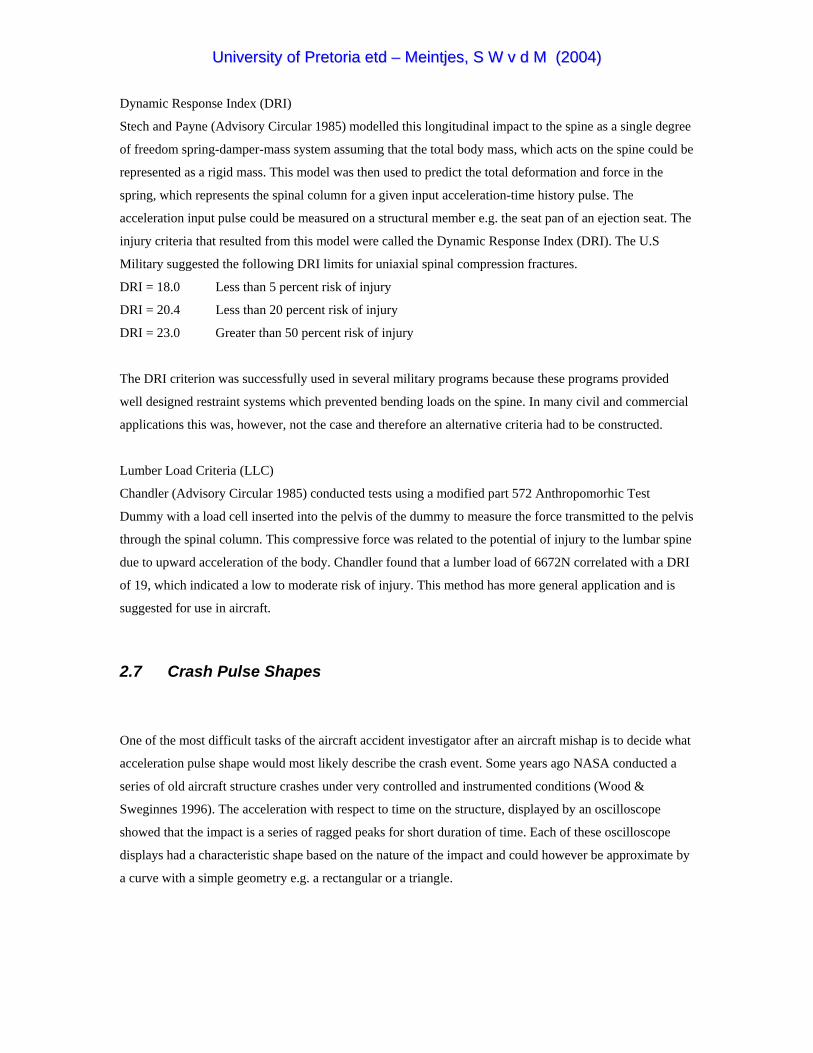
Rectangular Pulse Shape
This pulse requires unchanging acceleration over the impact period and implies minimum peak G’s
sustained by the object. Examples include normal landings with constant braking and wheels up landing on
snow or ice (See Figure 2.6).
Triangular Pulse Shapes
These events include constantly changing acceleration levels, either increasing, decreasing or a
combination. Examples of increasing acceleration (Figure 2.7) include impacting mud, dirt or a crash that
creates a deep crater.
Figure 2.6: Rectangular acceleration pulse shape (The Naval Flight Surgeon’s Pocket Reference to Aircraft Mishap Investigation 1995)
Figure 2.7: Increasing acceleration pulse shape (The Naval Flight Surgeon’s Pocket Reference to
Aircraft Mishap Investigation 1995)

UUnniivveerrssiittyy ooff PPrreettoorriiaa eettdd –– MMeeiinnttjjeess,, SS WW vv dd MM ((22000044))
Examples of decreasing acceleration (Figure 2.8) include skidding on pavement or impacting an object that
gradually gives way i.e. a tree.
Figure 2.8: Decreasing acceleration pulse shape (The Naval Flight Surgeon’s Pocket Reference to
Aircraft Mishap Investigation 1995)
According to The Naval Flight Surgeon’s Pocket Reference to Aircraft Mishap Investigation (1995), the
most common acceleration pulse shape encountered in aircraft mishaps is the increasing-decreasing pulse
shape shown in Figure 2.9. Although this crash pulse shape is an approximation at best it represents the
worst case scenario when peak accelerations are greatest e.g. aircraft flying through trees or a shallow angle
water entry.
Figure 2.9: Increasing decreasing acceleration pulse shape (The Naval Flight Surgeon’s Pocket Reference to Aircraft Mishap Investigation 1995)
In The Naval Flight Surgeon’s Pocket Reference to Aircraft Mishap Investigation (1995) and Wood &
Sweginnes (1996), it is stated that in the case of a general aviation accident the rectangular pulse shape
shown in Figure 2.6 would always represent the best case scenario and the equilateral triangle of Figure 2.9
would represent the worst case scenario.

UUnniivveerrssiittyy ooff PPrreettoorriiaa eettdd –– MMeeiinnttjjeess,, SS WW vv dd MM ((22000044))
2.8 Dynamic Crashworthiness Testing
According to Nicholson & Chapman (199-?), the Dynamic Crashworthiness Requirements for light aircraft
were introduced by the FAA in August 1988 and is contained in FAR Part 23.562 – Emergency Landing
Dynamic Conditions. FAR Part 23.562 were included in an attempt to improve the crashworthiness of light
aircraft in response to a perceived need. The National Transportation Safety Board conducted a study on
general aviation crashworthiness using the crash data of 1982. They concluded that the use of shoulder
harnesses in aircraft might have prevented 76% of the fatalities and 79% of the serious injuries. A similar
study on the proposed use of energy absorbing seats in general aviation aircraft indicated that 2% of
fatalities may have been prevented and 38% of the serious injuries may have been prevented by the use of
energy absorbing seats.
FAR Part 23.562 requires that the seat and restraint system undergo dynamic testing using a typical crash
pulse. Two tests are required to demonstrate compliance with FAR Part 23.562 with the purpose to
demonstrate that crash forces on the occupant have been attenuated to within human tolerances. Additional
requirements of FAR Part 23.562 state that the tests must be conducted using an ATD specified by 49 CFR
Part 572.
Because of the relevance of these tests to this study, it was decided to use them during one of the analysis
described in Chapter 4. The two dynamic tests that are required for compliance with FAR Part 23.562 are
specified as follow.
B. Except for those seat/restraint systems that are required to meet paragraph (d) of this section, each
seat/restraint system for crew or passenger occupancy in normal, utility, or acrobatic category aeroplane,
must successfully complete dynamic tests or be demonstrated by rational analysis supported by dynamic
tests, in accordance with each of the following conditions. These tests must be conducted with an occupant
simulated by an anthropomorphic test dummy (ATD) defined by 49 CFR Part 572, Subpart B or a FAA-
approved equivalent.
(1) For the first test, the change in velocity may not be less than 31 feet per second. The seat/restraint
system must be oriented in its nominal position with respect to the airplane and with the horizontal
plane of the airplane pitched up 60 degrees, with no yaw, relative to the impact vector. For
seat/restraint systems to be installed in the first row of the airplane, peak deceleration must occur in
not more than 0.05 seconds after impact and must reach a minimum of 19g. For all other seat/restraint
systems, peak deceleration must occur in not more than 0.06 seconds after impact and must reach a
minimum of 15g (see Figure 2.10).
UUnniivveerrssiittyy ooff PPrreettoorriiaa eettdd –– MMeeiinnttjjeess,, SS WW vv dd MM ((22000044))
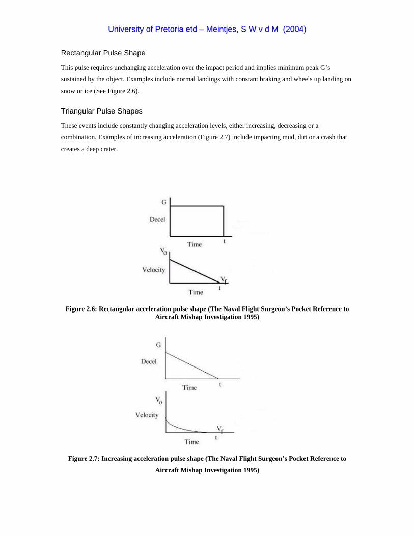
Figure 2.10: FAR 23.562 dynamic Test 1
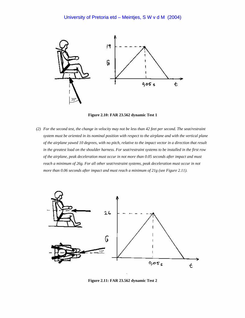
(2) For the second test, the change in velocity may not be less than 42 feet per second. The seat/restraint
system must be oriented in its nominal position with respect to the airplane and with the vertical plane
of the airplane yawed 10 degrees, with no pitch, relative to the impact vector in a direction that result
in the greatest load on the shoulder harness. For seat/restraint systems to be installed in the first row
of the airplane, peak deceleration must occur in not more than 0.05 seconds after impact and must
reach a minimum of 26g. For all other seat/restraint systems, peak deceleration must occur in not
more than 0.06 seconds after impact and must reach a minimum of 21g (see Figure 2.11).
Figure 2.11: FAR 23.562 dynamic Test 2
UUnniivveerrssiittyy ooff PPrreettoorriiaa eettdd –– MMeeiinnttjjeess,, SS WW vv dd MM ((22000044))
During these two tests the following requirements must be met in order to comply with the requirement.
C. Compliance with the following requirements must be shown during the dynamic tests conducted in
accordance with paragraph (b) of this section:
(1) The seat/restraint system must restrain the ATD although seat/restraint system components may
experience deformation, elongation, displacement, or crushing intended as part of the design.
(2) The attachment between the seat/restraint system and the test fixture must remain intact, although the
seat structure may have deformed.
(3) Each shoulder harness strap must remain on the ATD’s shoulder during the impact.
(4) The safety belt must remain on the ATD’s pelvis during the impact.
(5) The results of the dynamic tests must show that the occupant is protected from serious head injury.
(i)When contact with adjacent seats, structure, or other items in the cabin can occur, protection must
be provided so that the head impact does not exceed the head index criteria (HIC) of 1000.
(6) Loads in individual shoulder harness straps may not exceed 1750 pounds. If dual shoulder straps are
used for retaining the upper torso, the total strap loads may not exceed 2000 pounds.
(7) The compression load measured between the pelvis and lumbar spine of the ATD may not exceed 1500
pounds.
The exact same emergency landing dynamic condition is also specified in JAR-23 (2001). This
specification together with some other regulations on pilot protection in light aircraft is contained in
Appendix C.
2.9 Pilot Support Positions
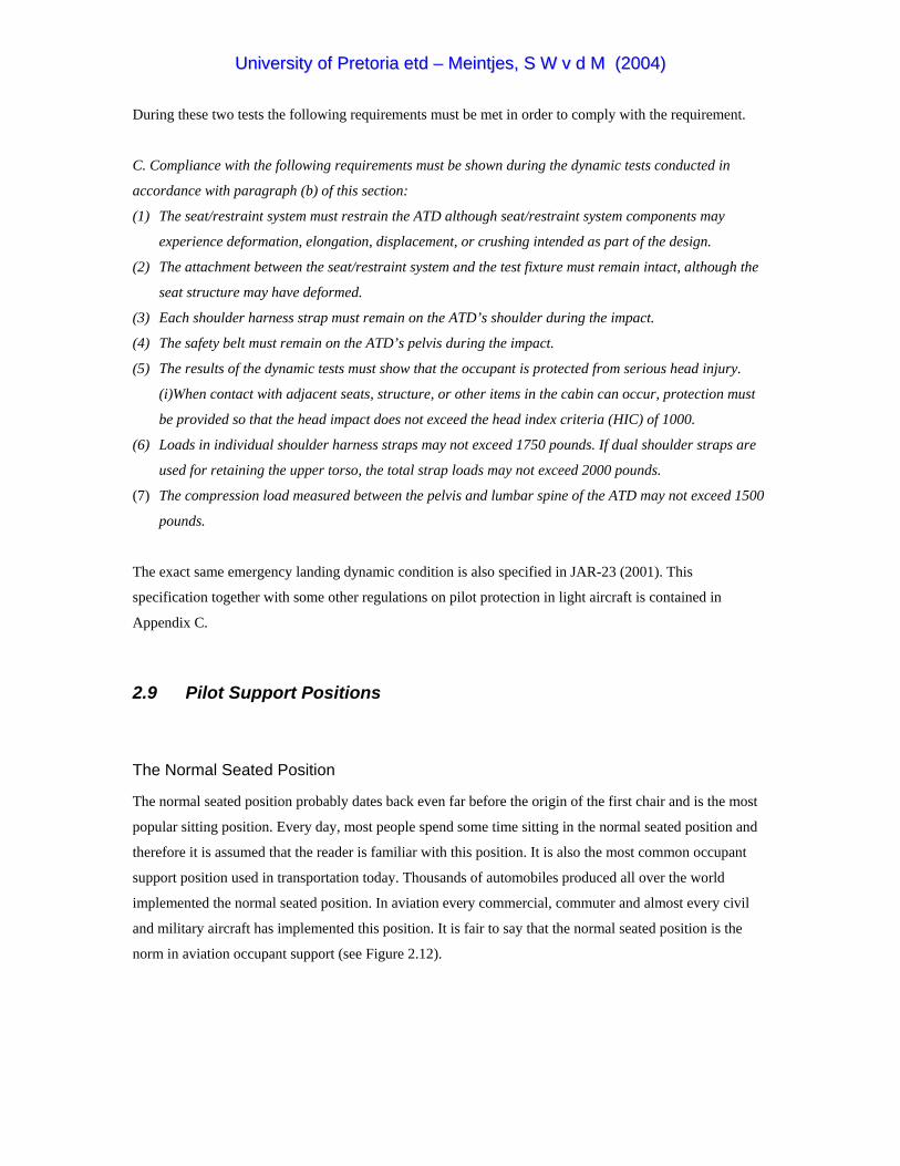
The Normal Seated Position
The normal seated position probably dates back even far before the origin of the first chair and is the most
popular sitting position. Every day, most people spend some time sitting in the normal seated position and
therefore it is assumed that the reader is familiar with this position. It is also the most common occupant
support position used in transportation today. Thousands of automobiles produced all over the world
implemented the normal seated position. In aviation every commercial, commuter and almost every civil
and military aircraft has implemented this position. It is fair to say that the normal seated position is the
norm in aviation occupant support (see Figure 2.12).

UUnniivveerrssiittyy ooff PPrreettoorriiaa eettdd –– MMeeiinnttjjeess,, SS WW vv dd MM ((22000044))
Figure 2.12: Aviator in the normal seated position (Advisory Circular 1993)
The advantage of such a universally accepted standard is that a lot of information concerning occupant
protection in this position already exists and was published. Some other advantages of the normal seated
position are that it offers a good field of vision and good comfort. It provides the pilot with a big volume in
which controls would be accessible and easy to reach. In civil aircraft, occupants in the normal seated
position are normally restrained by a three point restrained system as shown in Figure 2.13, while
aerobatics and military pilots are restrained by four or five point restraint systems shown by Figures 2.14(a)
and 2.14(b) respectively.
Figure 2.13: Three-point restraint (Advisory Circular 1993)

UUnniivveerrssiittyy ooff PPrreettoorriiaa eettdd –– MMeeiinnttjjeess,, SS WW vv dd MM ((22000044))
(a) (b)
Figure 2.14: Four and five-point restraint (Advisory Circular 1993)
The major disadvantages of this position are that the normal seated position would require a relative large
frontal fuselage area to house the pilot and seat construction. Head injury could most likely occur in this
position. This is especially true for pilots sitting in the cockpit area facing the instrument panel and control
stick. Head injury usually result from inadequate torso restraint due to slack in the shoulder straps or failure
of the torso restraint system. According to Richards & Podob (1997), compression of the lower lumbar
spine during high impact emergency landings often resulted in back injury to occupants in the normal
seated position. Additional injury due to arrestment by the webbing restraint system with little distribution
of impact pressure is also a disadvantage of this position. In conclusion the major advantages and
disadvantages are summarised.
Advantages
• Conventional, it has been implemented with success and a lot of data exist for this position
• Comfortable
• Good field of vision
• Provides a large volume with easy reachable flight controls
Disadvantages
• Results in a large frontal fuselage area
• Potential for head injury
• Potential for back injury during likely crash scenarios
• Potential for additional injury by webbing and buckles of restraint system
UUnniivveerrssiittyy ooff PPrreettoorriiaa eettdd –– MMeeiinnttjjeess,, SS WW vv dd MM ((22000044))
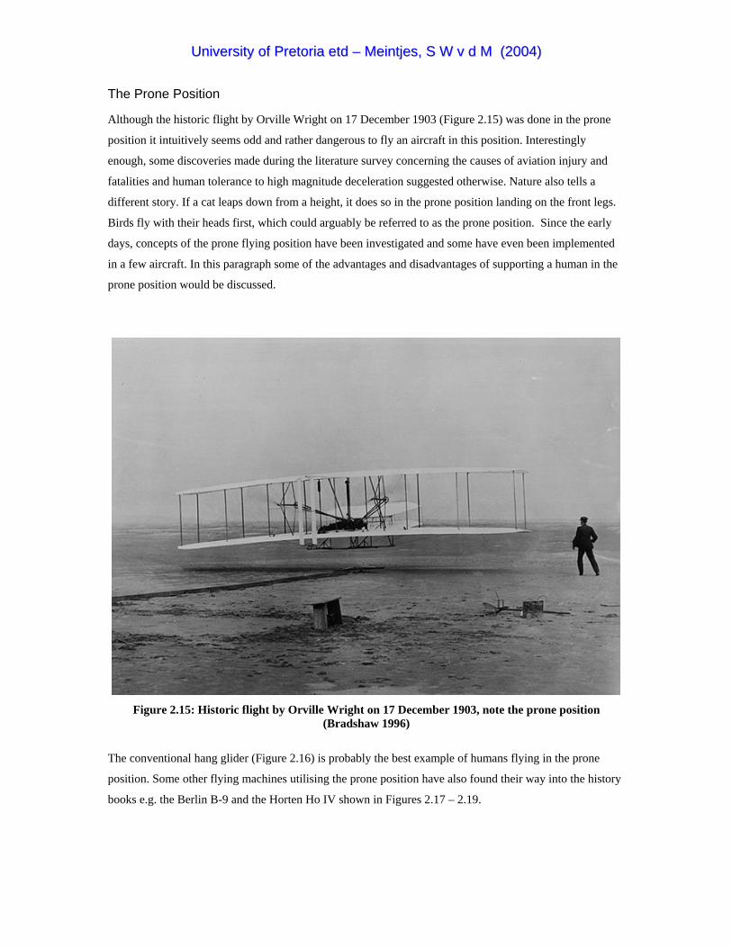
The Prone Position
Although the historic flight by Orville Wright on 17 December 1903 (Figure 2.15) was done in the prone
position it intuitively seems odd and rather dangerous to fly an aircraft in this position. Interestingly
enough, some discoveries made during the literature survey concerning the causes of aviation injury and
fatalities and human tolerance to high magnitude deceleration suggested otherwise. Nature also tells a
different story. If a cat leaps down from a height, it does so in the prone position landing on the front legs.
Birds fly with their heads first, which could arguably be referred to as the prone position. Since the early
days, concepts of the prone flying position have been investigated and some have even been implemented
in a few aircraft. In this paragraph some of the advantages and disadvantages of supporting a human in the
prone position would be discussed.
Figure 2.15: Historic flight by Orville Wright on 17 December 1903, note the prone position (Bradshaw 1996)
The conventional hang glider (Figure 2.16) is probably the best example of humans flying in the prone
position. Some other flying machines utilising the prone position have also found their way into the history
books e.g. the Berlin B-9 and the Horten Ho IV shown in Figures 2.17 – 2.19.

UUnniivveerrssiittyy ooff PPrreettoorriiaa eettdd –– MMeeiinnttjjeess,, SS WW vv dd MM ((22000044))
Figure 2.16: Hang glider with pilot in prone position (Couto 1999)
Figure 2.17: The Berlin B-9 prone pilot aircraft (Luftfahrt International 1975)

UUnniivveerrssiittyy ooff PPrreettoorriiaa eettdd –– MMeeiinnttjjeess,, SS WW vv dd MM ((22000044))
Figure 2.18: The Horten Ho IV flying wing with the pilot in the prone position (RFRL)
Figure 2.19: A close-up of the Ho IV showing the prone pilot position (RFRL)

UUnniivveerrssiittyy ooff PPrreettoorriiaa eettdd –– MMeeiinnttjjeess,, SS WW vv dd MM ((22000044))
Other interesting prone pilot position concepts under development are the MasterBlaster project (Testi
1998) and the Exulans II glider shown in Figures 2.20 and 2.21.
Figure 2.20: The MasterBlaster aerobatics aircraft concept with prone pilot (Testi 1998)
Figure 2.21: Exulans II glider with prone pilot

UUnniivveerrssiittyy ooff PPrreettoorriiaa eettdd –– MMeeiinnttjjeess,, SS WW vv dd MM ((22000044))
Racing motor cyclists travelling at speeds in excess of 250km/h are also supported in the riding position,
which shows a close resemblance with the prone position (Figure 2.22).
Figure 2.22: The rider of a super bike in the riding position (Valencia 2003)
Experiments with the prone pilot position started in the 1930’s when the DVL (German Aviation
Experimental Establishment) initiated a study to enable dive-bomb pilots to withstand higher G values
during the pull out. In 1937 the flight technical study group of the Berlin-Charlottenburg Technical High
School had build a small prone pilot aircraft the Berlin B-9 (Figure 2.17) to participate in this research
program. Early battle experience during World War II had indicated that the frontal area of a Focks-Wulf
190 provided a target that could be hit by a B-17 gunner at a range of more than 1000 yards. With the issue
of the German Air Ministry of a requirement for a small target defence interceptor, it was logical to propose
a prone position for the pilot to reduce the frontal area to the bare minimum.
In 1941 Alexander Lippisch also suggested the prone position as a flying position to enable pilots to
withstand higher low magnitude accelerations (less than 10g, longer than 1second) and to minimise the
fuselage frontal area. For the same reasons the Royal Air Force (RAF) Institute of Aviation Medicine
required an aircraft that could be flown by a pilot in the prone position. In 1954 the Gloster Meteor F8
(Prone Position) shown in Figure 2.23 joined the Institute of Aviation Medicine and after 55 hours of flight
testing it was concluded that the prone position concept was feasible. The development of special aviation

UUnniivveerrssiittyy ooff PPrreettoorriiaa eettdd –– MMeeiinnttjjeess,, SS WW vv dd MM ((22000044))
clothing however, offered a simpler solution to the counteracting of high g-forces and therefore the prone
position was abandoned (RAF MUSEUM). Although minimising the aircraft’s frontal area to avoid being
hit by a shell from a gunner is not a requirement of this project. A small frontal area implies less drag,
which leads to a higher efficiency aircraft, which is indeed a requirement of the Exulans project.
Figure 2.23: Gloster Meteor F8 prone pilot experimental aircraft (RAF MUSEUM)
Alexander Lippisch claims that the major drawback of flying in the prone position was the insufficient field
of vision enjoyed by fighter pilots. The fact that breathing discomfort could easily result from applied
pressure on the stomach and lower torso imply that special attention should be given to comfort and support
in the prone position. Another disadvantage is merely the fact that very little information on the prone
position is available in literature. To conclude this sub chapter the main advantages and disadvantages of
the prone position are summarised below.
Advantages
• The ability to withstand higher G-forces
• Allows for a smaller fuselage frontal area
• Higher human impact tolerance to likely crash scenarios
• Provides improved passive restraint opportunities
• Arguably smaller flailing envelope
• Eliminates the potential for “submarining”
• Occupant supporting structure offers protection to chest and abdominal penetration
• Lower chances for back injury due to vertebra compression
• Provides good opportunity for foot launching
Disadvantages
• Support needs special attention to provide sufficient comfort
• Often criticised for being harsh on neck muscles
• Unconventional, very little information available
UUnniivveerrssiittyy ooff PPrreettoorriiaa eettdd –– MMeeiinnttjjeess,, SS WW vv dd MM ((22000044))
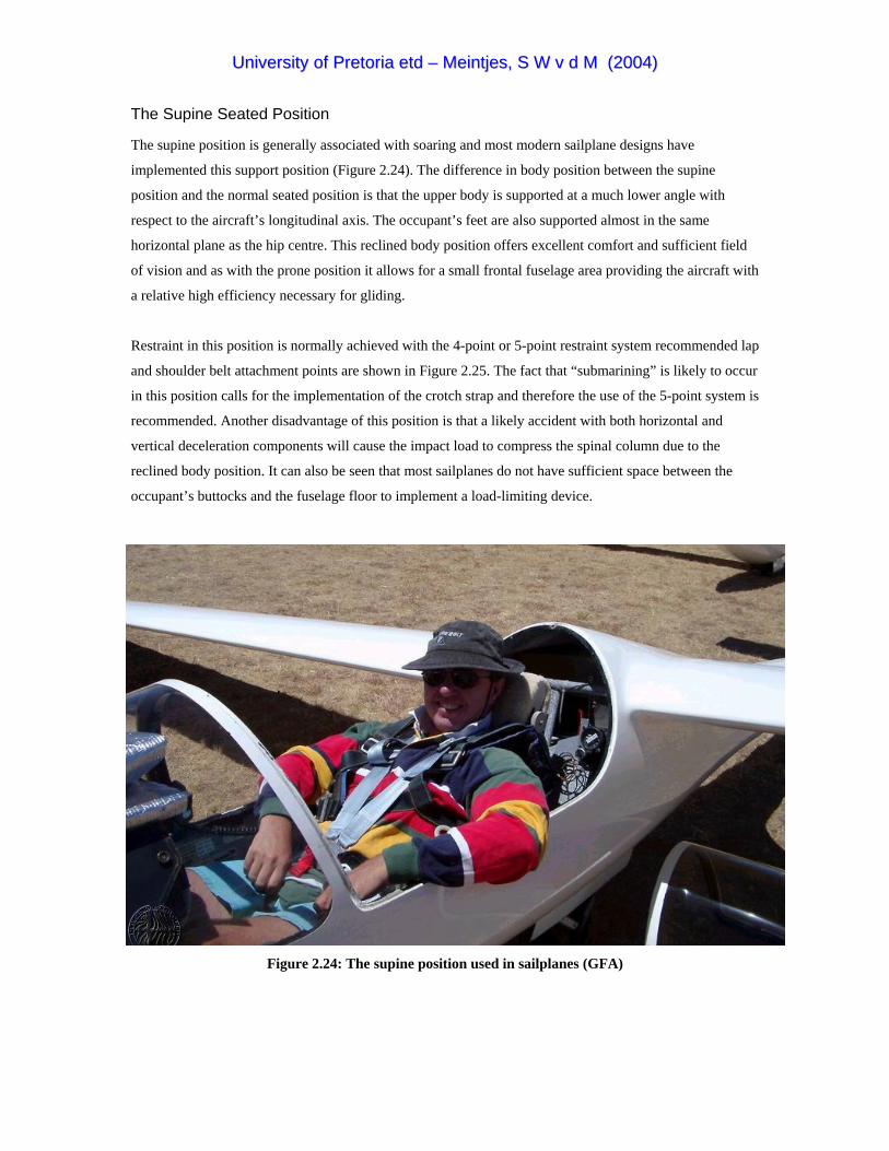
The Supine Seated Position
The supine position is generally associated with soaring and most modern sailplane designs have
implemented this support position (Figure 2.24). The difference in body position between the supine
position and the normal seated position is that the upper body is supported at a much lower angle with
respect to the aircraft’s longitudinal axis. The occupant’s feet are also supported almost in the same
horizontal plane as the hip centre. This reclined body position offers excellent comfort and sufficient field
of vision and as with the prone position it allows for a small frontal fuselage area providing the aircraft with
a relative high efficiency necessary for gliding.
Restraint in this position is normally achieved with the 4-point or 5-point restraint system recommended lap
and shoulder belt attachment points are shown in Figure 2.25. The fact that “submarining” is likely to occur
in this position calls for the implementation of the crotch strap and therefore the use of the 5-point system is
recommended. Another disadvantage of this position is that a likely accident with both horizontal and
vertical deceleration components will cause the impact load to compress the spinal column due to the
reclined body position. It can also be seen that most sailplanes do not have sufficient space between the
occupant’s buttocks and the fuselage floor to implement a load-limiting device.
Figure 2.24: The supine position used in sailplanes (GFA)
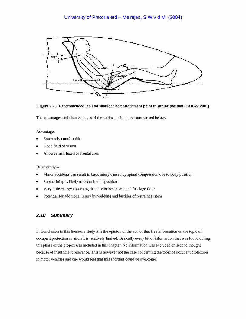
UUnniivveerrssiittyy ooff PPrreettoorriiaa eettdd –– MMeeiinnttjjeess,, SS WW vv dd MM ((22000044))
Figure 2.25: Recommended lap and shoulder belt attachment point in supine position (JAR-22 2001)
The advantages and disadvantages of the supine position are summarised below.
Advantages
• Extremely comfortable
• Good field of vision
• Allows small fuselage frontal area
Disadvantages
• Minor accidents can result in back injury caused by spinal compression due to body position
• Submarining is likely to occur in this position
• Very little energy absorbing distance between seat and fuselage floor
• Potential for additional injury by webbing and buckles of restraint system
2.10 Summary
In Conclusion to this literature study it is the opinion of the author that free information on the topic of
occupant protection in aircraft is relatively limited. Basically every bit of information that was found during
this phase of the project was included in this chapter. No information was excluded on second thought
because of insufficient relevance. This is however not the case concerning the topic of occupant protection
in motor vehicles and one would feel that this shortfall could be overcome.
UUnniivveerrssiittyy ooff PPrreettoorriiaa eettdd –– MMeeiinnttjjeess,, SS WW vv dd MM ((22000044))
The majority of the work done on this topic was focused on military application, especially on U.S Military
helicopters with pilots supported in the normal seated position. Virtually no data exist for occupants
supported in flying positions other than the normal seated position. Although energy absorption and
restraint are only two of the five crash survival design considerations, it seems that these two factors were
the most popular topics in the variety of past load limiting seat/restraint systems research projects. The
subject of airframe crashworthiness or “container” design deserves more attention and it seems that the
recommendations in the literature concerning this subject are much more severe than those found in the
aviation regulations.
The literature study provided useful insight and essential data to the project. The thesis specifications and
the concept proposal for the Exulans pilot protection system were based on the findings of the literature
study and are contained in the following chapter.
UUnniivveerrssiittyy ooff PPrreettoorriiaa eettdd –– MMeeiinnttjjeess,, SS WW vv dd MM ((22000044))
CHAPTER 3: PROPOSED CONCEPTS
Preview
1. The thesis specifications are stated in non-specific terms as an introduction to this chapter.
2. The pilot support concept is proposed to the reader followed by the philosophy behind this
proposal.
3. Some results of the ergonomical investigation are also contained in this chapter.
4. Concepts for the structural and systems design of the Exulans II fuselage are proposed under the
headings of the five CREEP design factors.
UUnniivveerrssiittyy ooff PPrreettoorriiaa eettdd –– MMeeiinnttjjeess,, SS WW vv dd MM ((22000044))
3.1 Thesis Specifications
As part of the development of a pilot protection system for Exulans, this thesis will investigate pilot
protection in light aircraft in general but more specifically it will launch a comparative study into different
pilot support positions. The specifications for this thesis are listed as follow:
1. Investigate common causes of aviation fatalities
2. Investigate human impact tolerance limits and injury thresholds
3. Investigate occupant crash protection requirements set by the authorities
4. Investigate different pilot support positions
5. Investigate restraining methods
6. Compare the crash response of a pilot in the prone position to that of other support positions
7. Generate recommendations and guidelines for the design of the Exulans II pilot protection system
Although meeting all the requirements of the specifications for the development of the pilot protection
system for Exulans II is not considered a goal for this thesis, they were also included as background
information. These specifications are categorised below as ergonomical and structural specifications.
ERGONOMICAL SPECIFICATIONS
1. Investigate the following ergonomical challenges:
• Getting in and out of the glider
• Pilot support and restraint
• Flight control actions in the support position
• Layout of controls and instrument panels
• Pilot field of vision
2. Provide a pilot support system that is both comfortable and safe. The support system must be designed
for a pilot wearing a personal parachute
3. One flight may last several hours therefore the pilot should be able to relax in the support position
without excessive strain on any part of the body.
4. Provide comfortable restraining methods that will not contribute to injuries during a crash. Restraints
should be applied to portions of the body best able to withstand high impact forces and accelerations
like the shoulders and pelvis.
5. The restraint locking mechanisms should be reachable and detachable during every instance and
aircraft attitude.

UUnniivveerrssiittyy ooff PPrreettoorriiaa eettdd –– MMeeiinnttjjeess,, SS WW vv dd MM ((22000044))
STRUCTURAL SPECIFICATIONS
1. Provide a container that would maintain an occupiable space during a survivable crash (It is
recommended that the container should be designed for a 40g ultimate load).
2. The design of the container should allow it to be deflected or rotated into an attitude where energy
absorption could proceed in a controlled manner.
3. The container should have the smallest possible frontal area and roll over protection should be
considered.
4. Provide energy absorbing mechanisms and materials in the structural design that would attenuate crash
forces to tolerable levels during a survivable crash.
5. Provide a cockpit environment cleared from any potentially harmful objects.
6. Implement breakaway features in the control stick and apply padding at potential impact surfaces.
7. Push rods close to the pilot must be placed strategically, not in line with any part of the body.
8. Provide the fuselage with a ballistic parachute.
9. Provide a method to evacuate the fuselage after a survivable crash.
10. On the ground the pilot must be accessible from outside the fuselage.
11. Provide a method for a mid-air bailout.
3.2 Proposed Pilot Support Position
During this subchapter the proposal of the prone pilot position for Exulans is introduced to the reader.
Previous studies by the author (Meintjes 1999) and Hanique (2002) investigated the ergonomical feasibility
of the prone position as a pilot support position specifically for Exulans. These studies concluded that the
pilot’s upper torso should be supported onto a chest plate and leg supports should be applied above and
below the knees. To provide the necessary comfort, the supports must be lined with a soft material. The
pilot’s feet should rest on feet supports and connecting the pilot’s harness to the airframe structure would
provide restraint and additional support. The detail of the proposed prone pilot support position is included
in the ergonomical investigation below and is followed by a subchapter stating the reasons that led to this
proposal.
The Ergonomical Investigation
A previous study by the author (Meintjes 1999) suggested that the pilot’s chest should be supported at an
angle between 25° and 30° for optimum comfort. This study also indicated that support beneath the elbows
greatly enhanced the pilot’s comfort by especially relieving some of the pressure experienced on the chest
(see Figure 3.1).

UUnniivveerrssiittyy ooff PPrreettoorriiaa eettdd –– MMeeiinnttjjeess,, SS WW vv dd MM ((22000044))
Figure 3.1: Prone pilot position ergonomical investigation (Meintjes 1999)
During a further study by Hanique (2002), a steel frame mock-up (Figure 3.2) was constructed to
investigate the following ergonomical aspects:
• Getting in and out of the prone seat
• The supporting method
• The restraining method
• Pilot comfort
• Flight control actions in the prone position
• Pilot field of vision
• Layout of controls and instrument panel
Figure 3.2: Steel frame mock-up (Hanique 2002)

UUnniivveerrssiittyy ooff PPrreettoorriiaa eettdd –– MMeeiinnttjjeess,, SS WW vv dd MM ((22000044))
In this mock-up the pilot was supported on a fixed chest plate with an angle of approximately 30° with
respect to the horizon. The hip bones in the pelvic region provided good supporting points and additional
comfort was achieved with the padded upper leg supports. The knee supports prevented the pilot from
slipping down the angle created by the chest plate and also removed some of the pressure from the chest.
The pilot’s feet were supported on a footrest and support beneath the elbows was provided as suggested
previously.
3.3 Reasons Leading to the Pilot Support Proposal
Several reasons led to the suggestion of supporting the Exulans pilot in the prone position. During the
literature study it was discovered that the human body could tolerate the highest impact load in the chest to
back or eyeballs out (-Gx) direction. During a likely crash scenario this would also be the direction of
application of a crash load to a pilot in the prone position as indicated by Figure 3.3
Figure 3.3: Direction of impact load on prone pilot during likely crash scenario
Head injury is responsible for a third of all aviation fatalities and is often due to improper torso restraint
(The Naval Flight Surgeon’s Pocket Reference to Aircraft Mishap Investigation 1995). The prone position
would offer excellent opportunity to support the pilot’s torso onto a passive restraint system or mechanism.
Back injury would also be limited in the prone position due to the fact that there would be no seat structure
behind the pilot that would apply a dangerous compressive force to the spine during a crash. Internal organ
damage caused by impact into the restraining webbing and “submarining” would also be eliminated and it
could be argued that the pilot in the prone position would have a small flail volume.

UUnniivveerrssiittyy ooff PPrreettoorriiaa eettdd –– MMeeiinnttjjeess,, SS WW vv dd MM ((22000044))
The capability of Exulans to perform a high angle of attack or flared landing due to its tailless configuration
was previously mentioned. This action is executed during the landing, just before touchdown and implies
that pilot error during this manoeuvre could be fatal due to the fact that the aircraft would have no altitude
to recover from the mistake. Looking at the dynamics of the flared landing action represented in Figure 3.4
it seems that performing this action in the normal seated or supine seated position would compromise the
pilots safety and field of vision as indicated in Figure 3.4 (a). The prone position would however result in
an almost upright body position with respect to the landing surface as shown by Figure 3.4 (b). Finally the
prone position offers excellent field of vision and would result in a much smaller fuselage frontal area
required for high efficient flight.
Figure 3.4: High angle of attack landing executed in different pilot positions
The ultra-light construction of Exulans together with the proposal of the prone pilot position offered an
excellent opportunity to implement and introduce this proposal to the aviation community. It was also
learned from the literature study that designing a crashworthy aircraft involves the consideration of five
factors known as the CREEP design factors. During the following subchapter concepts for the structural
design of the fuselage are proposed in consideration with these factors.

UUnniivveerrssiittyy ooff PPrreettoorriiaa eettdd –– MMeeiinnttjjeess,, SS WW vv dd MM ((22000044))
3.4 CREEP Concept Design Proposals
3.4.1 Container Concept
The Exulans airframe or container concept is shown as a CAD drawing in Figure 3.5. The aim of the
container design is to establish a very strong lightweight construction that would not fracture but rather be
deflected into an attitude where energy could be dissipated in a controlled manner. To achieve the rigid
lightweight construction, the parts could be manufactured from carbon fibre composite material with high-
density polystyrene as the sandwich material. It is desirable to design these parts for a 40g ultimate load as
stated by The Naval Flight Surgeon’s Pocket Reference to Aircraft Mishap Investigation (1995) and Wood
& Sweginnes (1996). The strength of these parts is however limited by the strict weight limitation of this
ultra-light glider.
Figure 3.5: Exulans II container concept

UUnniivveerrssiittyy ooff PPrreettoorriiaa eettdd –– MMeeiinnttjjeess,, SS WW vv dd MM ((22000044))
3.4.2 Restraint Concept
The exceptionality of the prone pilot position implies that no conventional restraining method for this
position exists. As with the pilot support position proposal, the restraining method would be a unique
concept and should be designed following the basic restraining guidelines. One concept for a restraining
system in the prone position is the custom manufactured chest plate harness shown in Figure 3.6. The pilot
would fit the harness and tighten the belts to a comfortable fit before entering the cockpit. The harness
consists of a rigid chest plate and 45mm webbing extending from the chest plate over the shoulders,
through the legs, back to the chest plate. The blue padding between the composite chest plate and chest and
between the legs is provided to enhance the comfort of the harness.
Figure 3.6: Pilot wearing the custom manufactured harness

UUnniivveerrssiittyy ooff PPrreettoorriiaa eettdd –– MMeeiinnttjjeess,, SS WW vv dd MM ((22000044))
Inside the cockpit the pilot would connect the chest plate to the supporting structure through an energy
absorber, hence the passive torso restraint. Additional belts extending from the hips would restrain the
pelvis to the supporting structure. It is suspected that sufficient pelvic restraint in the prone position would
provide the advantage of tension rather than compression loading of the lumbar spine. This would be
contributed to the fact that the upper torso would displace forward during a crash. As the torso displaces
forward it will tension the spine which is restraint at the base by the pelvic belts. The harness connections
to the supporting structure could all be of the quick release type and the emergency parachute would also
be connected to the buckles on the harness’s shoulder straps. The legs would be supported above and below
the knees on padded leg supports and would be free to move from and to the supports as required. Footrests
would be provided.
3.4.3 Energy Absorption Concept
Energy absorption in Exulans is primarily achieved by three mechanisms. The first mechanism is the
collapsible landing skid shown in Figure 3.7. The collapsible landing skid mechanism consists of the skid,
skid strut, wheel strut and the energy-absorbing element. This mechanism operates on the basis of a
parallelogramming motion energy absorber described by Winkelman & Laananen (1996). Pivots at both
ends of the skid strut and wheel strut permits the parallelogramming motion of the landing skid mechanism
while the elongation of the diagonal energy-absorbing element absorbs energy.
Figure 3.7: Collapsible landing skid mechanism

UUnniivveerrssiittyy ooff PPrreettoorriiaa eettdd –– MMeeiinnttjjeess,, SS WW vv dd MM ((22000044))
The intention of the landing skid is that the pilot would manually retract it after take-off to avoid excessive
drag during flight. Before a landing or during an emergency situation the pilot would move the skid to its
extended position. The diagonal energy-absorbing element should preferably be an inexpensive readily
available component e.g. a rope, wire or strap, that could be replaced after a hard landing or specified time
in service.
Secondly, energy would be absorbed in the connection between the pilot’s chest plate and the aircraft
structure. This implies that the chest plate would be connected to an energy-absorbing material or
mechanism that would “stroke” or deform under a predefined load, subjecting the pilot to a lower
acceleration while crash energy is absorbed.
Thirdly it is assumed that the crushing and plastic deformation of the aircraft structure would absorb a
portion of the crash energy. Several studies including the publication by Farley (1983) suggested that high-
energy absorption could be achieved by the crushing of composite structures. The airframe of Exulans is
mainly constructed from carbon fibre sandwich components with high-density polystyrene as the core
material. It is however important that the fuselage structure does not fracture to such an extend that the
required living space could not be maintained.
3.4.4 Environment Considerations
It was previously mentioned that a clean environment should be provided within the occupant’s flailing
envelope. In the Exulans cockpit this would be achieved by eliminating any protruding sharp objects from
the pilot’s flail volume. Where objects could not be removed padding would be provided to protect the pilot
from injury. Energy-absorbing padding would also be provided at potential impact surfaces and brake away
features could be implemented into the controls.
3.4.5 Post-Crash Factors
Crash Survival Design Considerations states that the occupants should be able to evacuate the aircraft as
fast as possible after an emergency landing or high impact event. It could be argued that complying with
the first four factors of the CREEP considerations in the aircraft’s design, would limit injury to the
occupant. Without injury it is more likely that the occupants could escape additional injury or death caused
by post-crash factors.
To prevent the pilot from drowning after a water impact a fuselage structure that would float on water is
proposed. Furthermore, the Exulans fuselage would be provided with a quick-release fuselage back part
that would enable the pilot to create an exit by splitting the fuselage into two halves. Accessibility to the

UUnniivveerrssiittyy ooff PPrreettoorriiaa eettdd –– MMeeiinnttjjeess,, SS WW vv dd MM ((22000044))
occupant from the outside should also be provided in the design. Finally, the detachable fuselage back part
would also provide a means for a mid-air bailout and quick release from the restraining belts would also be
necessary.
3.5 Conclusion
In conclusion it could be stated that the aim of the Exulans II cockpit design is to establish a very strong
lightweight container that would provide and maintain the required living space of the pilot during a crash.
Sufficient restraint and energy-absorbing materials and mechanisms in the supporting structure and the
landing skid would avoid high crash loads applied to the pilot. Where body parts could not be restrained, a
clean environment would be provided and a mechanism for quick escape from the fuselage and restraints
after a mishap would be established.
Conceptually the fuselage layout and pilot protection strategy have been proposed. The next challenge
would be to compare the dynamic response of the proposed prone position with other pilot positions. The
dynamic analysis would also aid as a tool to quantify the forces and maximum accelerations in the structure
during impact scenarios.
UUnniivveerrssiittyy ooff PPrreettoorriiaa eettdd –– MMeeiinnttjjeess,, SS WW vv dd MM ((22000044))
CHAPTER 4: DYNAMIC ANALYSIS
Preview
1. This chapter contains the technical information of the dynamic analysis.
2. Initially the approach that was followed and the tools used during the analysis are discussed where
after the reader is formally introduced to the Hybrid III test pilots.
3. The models used for bench marking are then discussed under the heading of Validation and
Verification.
4. The two sets of dynamic analysis are then introduced to the reader and relevant results and
preliminary findings are also contained in this chapter.
5. Detailed discussions of each impact simulation analysis typically involve assumptions, modelling
techniques and input values.

UUnniivveerrssiittyy ooff PPrreettoorriiaa eettdd –– MMeeiinnttjjeess,, SS WW vv dd MM ((22000044))
4.1 The Approach
Growing computer technology and current event simulation software packages encourage engineers to do a
complete design and operation simulation of a mechanical system on the computer before spending any
time and money on prototype development. Due to the possible destructive nature of impact experiments it
was thought best to initially follow the computer analysis path in order to save both time and money.
Models of human pilots in the three different support positions were constructed and at first subjected to an
approximated crash pulse shape on a virtual test sled. The three pilots were then individually confined to
an aircraft cockpit to undergo a series of specified crash scenarios. Considering the difference in the
restraint methods and body tolerance to impact in the different positions, the response of the pilots in each
case was compared to each other and to injury criteria norms.
The two pilot positions that were compared against the prone position was the normal seated position found
in most motorised aircraft and the supine seated position found in many sailplane designs. During a
comparative study it is important to assure that apples are being compared to apples. Although it does not
always happen in reality it was assumed that the two pilots in the normal seated and supine seated positions
were restrained with optimum restraint configurations as specified by the aviation regulations. Because of
the fact that the aviation authorities have specified no restraining method for the prone position, different
configurations were investigated during the analysis. The best prone position restraining configuration was
selected for the comparison.
4.2 The Analysis Tools
The program ADAMS was used to run the impact simulations. It is a product of Mechanical Dynamics
Incorporated (MDI) and has the ability to simulate the dynamics of any mechanical system by generating
and solving the equations of motions for the system. The human models were obtained from FIGURE
human modeller, which is an add-on to ADAMS. A variety of human and other biological subjects are
available in FIGURE but the model with the Hybrid III Crush Dummy properties as specified in 49 CFR
572 was used for this study. Specified injury criteria was used to evaluate the impact effect on the Hybrid
III dummy and to compare the results obtained in the three different occupant support positions. The
capabilities and additional technical information on ADAMS and FIGURE are contained in Appendix D.

UUnniivveerrssiittyy ooff PPrreettoorriiaa eettdd –– MMeeiinnttjjeess,, SS WW vv dd MM ((22000044))
4.3 Meet the Pilots
The three pilots that will be exposed to crash pulse shapes on the test sled and who will crash the fuselage
airframes into the ground in the three different support positions will from now on be referred to as the
following:
The pilot in the normal seated position - The normal seated pilot
The pilot in the prone position - The prone pilot
The pilot in the supine seated position - The supine seated pilot
All three the pilots have a mass of 77kg and stand at a height of 1.778m. They are also referred to as
Anthropomorphic Test Devices (ATD’s) and have the dimensions, mass and joint properties of the 50th
percentile male Hybrid III crash test dummy specified by 49 CFR part 572.
To summarise for all the pilots:
Age: 27 years
Gender: 50th percentile male (Hybrid III)
Weight: 77kg
Length: 1.778m
Occupation: Test Pilot
The Normal Seated Pilot
The normal seated pilot will feature in al the normal seated configuration analysis and can be recognised by
the normal seated position and blue coloured body parts as indicated in Figure 4.1. ADAMS measurements
and results for the normal seated pilot will always be represented by a blue coloured curve on graphs.
The Prone Pilot
The prone pilot will test all the prone support position configurations. The prone pilot can be recognised by
the prone position and red coloured body parts as indicated by Figure 4.2. ADAMS measurements and
results for the prone pilot will always be represented by a red coloured curve on graphs.
The Supine Seated Pilot
The supine seated pilot will be used during the supine seated impact analysis. The supine seated pilot can
be recognised by the supine position and green coloured body parts. The supine seated pilot is shown in
Figure 4.3. ADAMS measurements and results for the supine seated pilot will always be represented by a
green coloured curve on graphs.

UUnniivveerrssiittyy ooff PPrreettoorriiaa eettdd –– MMeeiinnttjjeess,, SS WW vv dd MM ((22000044))
Figure 4.1: The normal seated pilot in the normal seated position
Figure 4.2: The prone pilot in the prone position
Figure 4.3: The supine seated pilot in the supine position

UUnniivveerrssiittyy ooff PPrreettoorriiaa eettdd –– MMeeiinnttjjeess,, SS WW vv dd MM ((22000044))
4.4 Validation and Verification
Objective
The objective of the result verification process was to validate data obtained from the ADAMS impact
analysis by comparing the results to that obtained from a similar impact experiment. It is normally good
practice to verify results obtained from computer analysis with experimental results. Due to technical and
limited time and financial factors it was, however, not feasible to perform the impact experiments similar to
the virtual impact tests described in this chapter and an alternative route to validate the ADAMS data had to
be followed. Using existing data from an experiment of the same nature seemed to be the next logical
solution. Land Mobility Technologies (LMT) in association with Armscor has been involved in evaluating
human response to impact and, much appreciated by the author, have agreed to provide the data on a
previous vertical impact experiment.
Experimental Set-up
The experiment by Armscor and LMT involved a vertical upward 26g impulse applied to a 50th percentile
male Hybrid III ATD. The normal upright seated ATD was placed onto a steel rig that was bolted to a
hydro pulse actuator (Figure 4.4). The ATD was restrained with a lap belt and the required maximum
acceleration was achieved by applying a rapid displacement (see Figure E1) to the seat rig. Measurements
taken from the ATD included spinal compression force Fz, spine acceleration Az, ankle compression Fz,
neck compression Fz, neck shear Fx and neck bending moment My, head accelerations Ax, Ay, Az and the
lap belt force (see Figure A4 for axes definition).
Figure 4.4: Vertical impact experiment with Hybrid III ATD (Courtesy of Armscor and LMT)

UUnniivveerrssiittyy ooff PPrreettoorriiaa eettdd –– MMeeiinnttjjeess,, SS WW vv dd MM ((22000044))
The ADAMS Model
The ADAMS model consisted of the steel test rig modelled as a rigid body, the steel seat blocks also
modelled as rigid bodies and the FIGURE 50th percentile male Hybrid III ATD. The body position of the
ADAMS dummy was adjusted to that of the experimental dummy and the lap belt was simulated with three
non-linear spring-dampers (one on each side and one over the dummy’s lap). As in the experiment the seat
rig acceleration was achieved by applying a rapid upward displacement to the rig. The ADAMS model is
shown in Figure 4.5.
Figure 4.5: ADAMS model of vertical impact experiment
Validation Results
The measurements used to compare the ADAMS results with the experimental results were the lumbar
spine force Fz (Figure 4.6) for evaluating the LLC and the dummy’s head acceleration magnitude (Figure
4.7) to calculate the HIC value. In the following graphs the ADAMS results (red) were superimposed onto
the experimental results (blue).

UUnniivveerrssiittyy ooff PPrreettoorriiaa eettdd –– MMeeiinnttjjeess,, SS WW vv dd MM ((22000044))
Figure 4.6: Lumbar spine force comparison
Figure 4.7: Head acceleration magnitude comparison
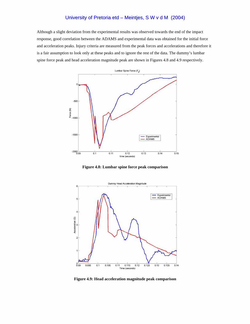
UUnniivveerrssiittyy ooff PPrreettoorriiaa eettdd –– MMeeiinnttjjeess,, SS WW vv dd MM ((22000044))
Although a slight deviation from the experimental results was observed towards the end of the impact
response, good correlation between the ADAMS and experimental data was obtained for the initial force
and acceleration peaks. Injury criteria are measured from the peak forces and accelerations and therefore it
is a fair assumption to look only at these peaks and to ignore the rest of the data. The dummy’s lumbar
spine force peak and head acceleration magnitude peak are shown in Figures 4.8 and 4.9 respectively.
Figure 4.8: Lumbar spine force peak comparison
Figure 4.9: Head acceleration magnitude peak comparison
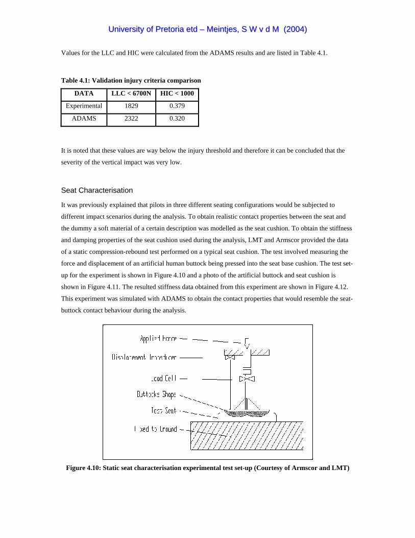
UUnniivveerrssiittyy ooff PPrreettoorriiaa eettdd –– MMeeiinnttjjeess,, SS WW vv dd MM ((22000044))
Values for the LLC and HIC were calculated from the ADAMS results and are listed in Table 4.1.
Table 4.1: Validation injury criteria comparison
DATA LLC < 6700N HIC < 1000
Experimental 1829 0.379
ADAMS 2322 0.320
It is noted that these values are way below the injury threshold and therefore it can be concluded that the
severity of the vertical impact was very low.
Seat Characterisation
It was previously explained that pilots in three different seating configurations would be subjected to
different impact scenarios during the analysis. To obtain realistic contact properties between the seat and
the dummy a soft material of a certain description was modelled as the seat cushion. To obtain the stiffness
and damping properties of the seat cushion used during the analysis, LMT and Armscor provided the data
of a static compression-rebound test performed on a typical seat cushion. The test involved measuring the
force and displacement of an artificial human buttock being pressed into the seat base cushion. The test set-
up for the experiment is shown in Figure 4.10 and a photo of the artificial buttock and seat cushion is
shown in Figure 4.11. The resulted stiffness data obtained from this experiment are shown in Figure 4.12.
This experiment was simulated with ADAMS to obtain the contact properties that would resemble the seat-
buttock contact behaviour during the analysis.
Figure 4.10: Static seat characterisation experimental test set-up (Courtesy of Armscor and LMT)

UUnniivveerrssiittyy ooff PPrreettoorriiaa eettdd –– MMeeiinnttjjeess,, SS WW vv dd MM ((22000044))
Figure 4.11: Artificial buttock with typical seat cushion (Courtesy of Armscor and LMT)
Figure 4.12: Seat stiffness data obtained from static test (Courtesy of Armscor and LMT)
During the ADAMS simulation of this experiment a trail and error method was used to obtain the contact
coefficients. The lower torso (pelvis) of the 50th percentile FIGURE male Hybrid III model was used as the
artificial buttock. The pelvis was forced into a block resembling the seat cushion (see Figure 4.13). The
ADAMS contact coefficients were modified until a similar force-displacement curve was obtained for the
ADAMS seat cushion model as indicated in Figure 4.14. The experimental result is indicated in blue while
the ADAMS result is shown in red.
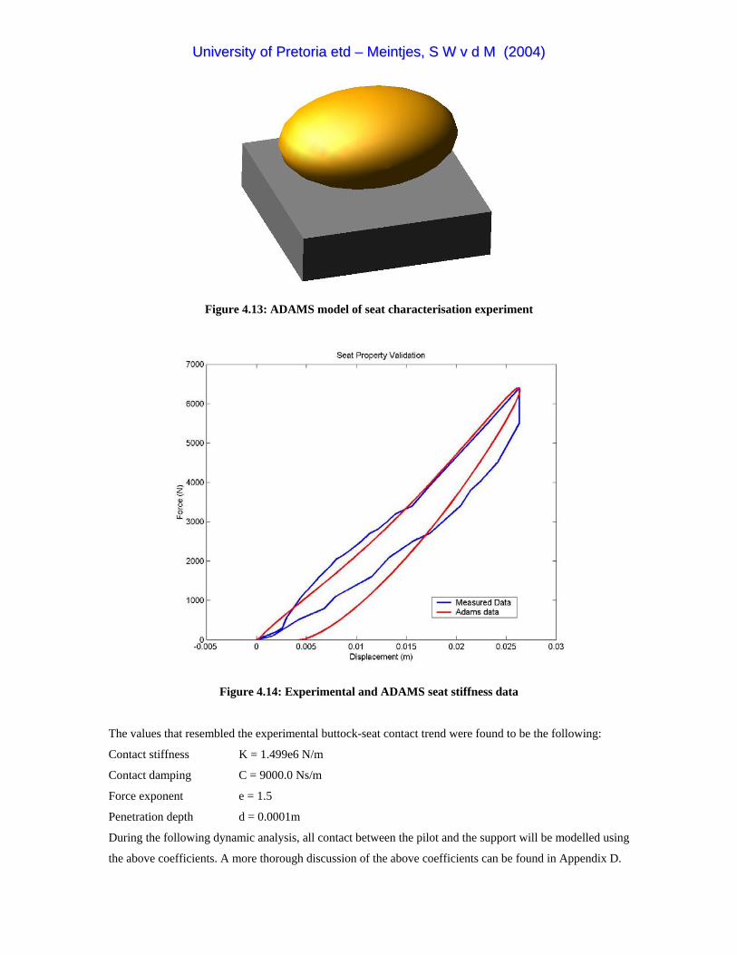
UUnniivveerrssiittyy ooff PPrreettoorriiaa eettdd –– MMeeiinnttjjeess,, SS WW vv dd MM ((22000044))
Figure 4.13: ADAMS model of seat characterisation experiment
Figure 4.14: Experimental and ADAMS seat stiffness data
The values that resembled the experimental buttock-seat contact trend were found to be the following:
Contact stiffness K = 1.499e6 N/m
Contact damping C = 9000.0 Ns/m
Force exponent e = 1.5
Penetration depth d = 0.0001m
During the following dynamic analysis, all contact between the pilot and the support will be modelled using
the above coefficients. A more thorough discussion of the above coefficients can be found in Appendix D.

UUnniivveerrssiittyy ooff PPrreettoorriiaa eettdd –– MMeeiinnttjjeess,, SS WW vv dd MM ((22000044))
4.5 Sled Impact Tests
It was previously mentioned that in order to make sensible comparisons between the three support
concepts, it is important to insure that apples are being compared to apples. The test sled was therefore
introduced to compare the different pilot positions under similar dynamic conditions. Models of the
different seat-restraint configurations was placed on the virtual test sled and exposed to exactly the same
impact pulse shape. Conventional restraining methods found in light aircraft were used for the normal
seated and supine seated positions. No conventional restraining methods exist for the prone position and
therefore the sled impact test provided a golden opportunity to test different restraining concepts. The
results of these tests were then evaluated with the specified injury criteria and compared with each other.
According to FAR Part 23.562, the ATD on the sled should be subjected to two different dynamic tests.
The first test generally involves a vertical drop with the aircraft seat pitched 30° downward from the
horizontal plane. The second test involves a horizontal frontal impact with the seat yawed 10°. As in real
life, the test sleds were modelled in such a way that it could only translate in the direction of the track,
constraining all rotations and other translations. The translation constraints and applied acceleration vector
for Test 1 and Test 2 are shown by Figure 4.15 and Figure 4.16 respectively.
Figure 4.15: Test 1 model with translation constraints and applied crash pulse vector.

UUnniivveerrssiittyy ooff PPrreettoorriiaa eettdd –– MMeeiinnttjjeess,, SS WW vv dd MM ((22000044))
Figure 4.16: Test 2 model with translation constraints and applied crash pulse vector.
The seat structures were modelled as rigid bodies fixed to the sled, resulting in no elastic or plastic
deformation of the seat structure, thus leaving the seat structure with no energy-absorbing capabilities. The
pilots were constrained to the seats with the respective restraint systems modelling the belts as 50mm
Nylon webbing as specified in Appendix B. The webbing was modelled as one directional non-linear
spring-dampers that could only transmit tension. According to Appendix B, Nylon webbing would show an
elongation of 17% under a load of 11120N while Dacron webbing would show an elongation of only 8%
under the 11120N load. This information could be translated as one point on the force-displacement curve
of the two different materials. Assuming that the webbing would posses a non-linear increasing stiffness
due to the geometrical effect of the fibre weave, the shape of the stiffness curves were plotted as indicated
in Figure 4.17 for the two different materials, blue representing Nylon and red representing Dacron. The
elongation for each belt in the ADAMS models was scaled according to the blue Nylon curve.

UUnniivveerrssiittyy ooff PPrreettoorriiaa eettdd –– MMeeiinnttjjeess,, SS WW vv dd MM ((22000044))
Figure 4.17: Webbing stiffness curves
Belt slack and belt pretension was modeled using the ADAMS spline function. An example of this
technique is shown in Figure 4.18. From the belt pretension curve it can be seen that there is already a
2000N pretension force in the belt at zero elongation and from the belt slack curve it can be seen that there
is approximately 2% elongation of the belt at zero force. This zero force elongation represents the slack in
the belt that has to be taken up before the belt is actually tensioned.
Figure 4.18: Modelling belt slack and belt pretension with the ADAMS spline function

UUnniivveerrssiittyy ooff PPrreettoorriiaa eettdd –– MMeeiinnttjjeess,, SS WW vv dd MM ((22000044))
During the sled impact tests for all three seating configurations, energy absorption in the seat or support
padding was modelled by specifying a contact stiffness and damping between the ATD and the seat or
support. The magnitude of these values was obtained during the seat validation process described in the
previous subchapter.
The pulse shape specified by FAR Part 23.562 is the triangular increasing decreasing pulse with a velocity
change of no less than 9.45 m/s, a rise time of no more than 0.05 seconds and a peak deceleration of no less
than 19G for the first test. For the second test the change in velocity must be no less than 12.8 m/s with a
rise time not exceeding 0.05 seconds and a minimum peak deceleration of 26G. Using the specified limit
values the pulse shapes for the sled tests could be calculated using the formulas found in Simula
Incorporated (1980). The pulse shape calculation for Test 1 is shown in Figure 4.19 and Figure 4.20 shows
the calculation for Test 2.
Figure 4.19: Pulse shape calculation for Test 1
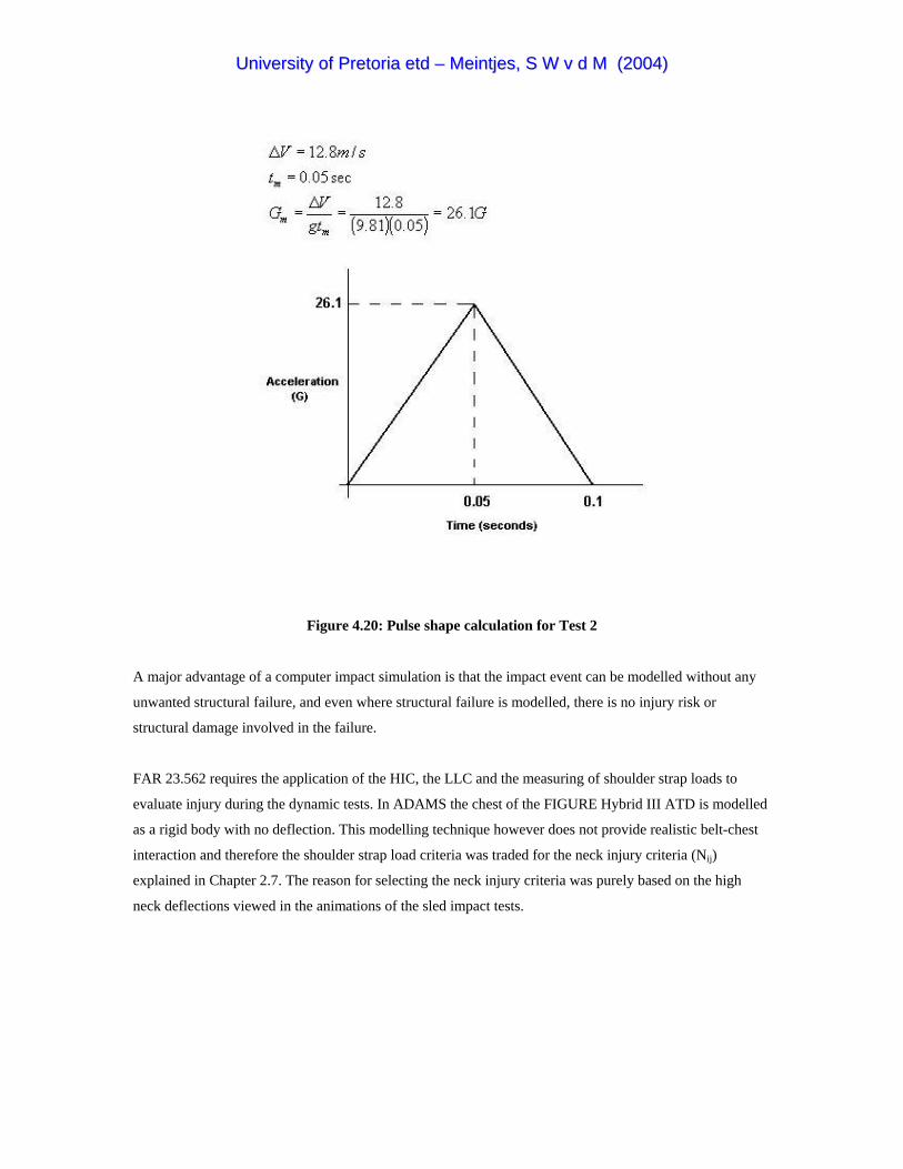
UUnniivveerrssiittyy ooff PPrreettoorriiaa eettdd –– MMeeiinnttjjeess,, SS WW vv dd MM ((22000044))
Figure 4.20: Pulse shape calculation for Test 2
A major advantage of a computer impact simulation is that the impact event can be modelled without any
unwanted structural failure, and even where structural failure is modelled, there is no injury risk or
structural damage involved in the failure.
FAR 23.562 requires the application of the HIC, the LLC and the measuring of shoulder strap loads to
evaluate injury during the dynamic tests. In ADAMS the chest of the FIGURE Hybrid III ATD is modelled
as a rigid body with no deflection. This modelling technique however does not provide realistic belt-chest
interaction and therefore the shoulder strap load criteria was traded for the neck injury criteria (Nij)
explained in Chapter 2.7. The reason for selecting the neck injury criteria was purely based on the high
neck deflections viewed in the animations of the sled impact tests.

UUnniivveerrssiittyy ooff PPrreettoorriiaa eettdd –– MMeeiinnttjjeess,, SS WW vv dd MM ((22000044))
4.5.1 Normal Seated Position
The normal seated pilot was placed on a seat in the upright normal seated body position simulating a grip
on to the control stick. The ADAMS contact properties resulting from the seat characterisation described in
Chapter 4.4 were used to simulate realistic dummy-seat contact. The normal seated pilot was restraint with
the four-point restraint system indicated in Figure 2.15(a). The trailing lengths of the shoulder straps were
connected to the seat structure at the prescribed range of angles with the shoulder’s connection point as
indicated in Figure B11. Belt slack in the shoulder straps was introduced by modelling the non-linear
shoulder strap spring dampers with a 100mm no resistance elongation as explained in Figure 4.18. The lap
belt was connected to the seat structure at the recommended angle of 45° to limit both forward and upward
motion of the pelvis (Figure B4). A pretension of 100N was modelled in the non-linear lap belt spring
dampers as explained in Figure 4.18. The ADAMS model of the normal seated pilot on the test sled is
shown in Figure 4.21. In this figure and following figures, a belt connection to the structure will be
indicated by a triangular symbol while a belt connection to the pilot’s body will be indicated by a circular
symbol.
Figure 4.21: Test sled with normal seated configuration
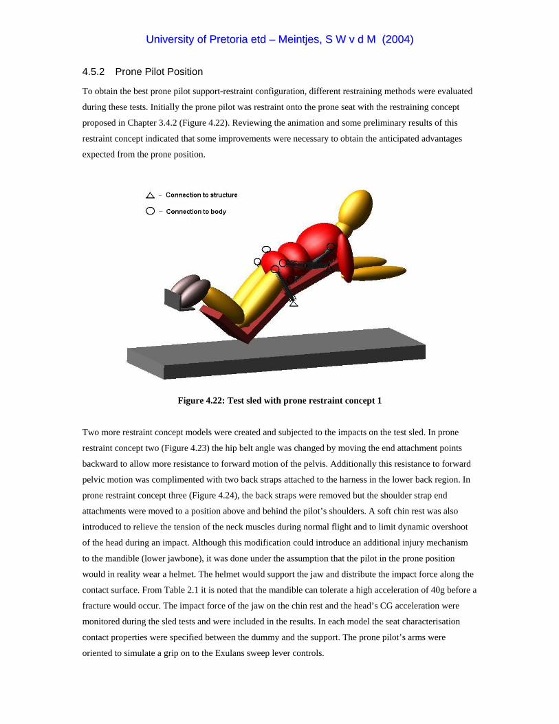
UUnniivveerrssiittyy ooff PPrreettoorriiaa eettdd –– MMeeiinnttjjeess,, SS WW vv dd MM ((22000044))
4.5.2 Prone Pilot Position
To obtain the best prone pilot support-restraint configuration, different restraining methods were evaluated
during these tests. Initially the prone pilot was restraint onto the prone seat with the restraining concept
proposed in Chapter 3.4.2 (Figure 4.22). Reviewing the animation and some preliminary results of this
restraint concept indicated that some improvements were necessary to obtain the anticipated advantages
expected from the prone position.
Figure 4.22: Test sled with prone restraint concept 1
Two more restraint concept models were created and subjected to the impacts on the test sled. In prone
restraint concept two (Figure 4.23) the hip belt angle was changed by moving the end attachment points
backward to allow more resistance to forward motion of the pelvis. Additionally this resistance to forward
pelvic motion was complimented with two back straps attached to the harness in the lower back region. In
prone restraint concept three (Figure 4.24), the back straps were removed but the shoulder strap end
attachments were moved to a position above and behind the pilot’s shoulders. A soft chin rest was also
introduced to relieve the tension of the neck muscles during normal flight and to limit dynamic overshoot
of the head during an impact. Although this modification could introduce an additional injury mechanism
to the mandible (lower jawbone), it was done under the assumption that the pilot in the prone position
would in reality wear a helmet. The helmet would support the jaw and distribute the impact force along the
contact surface. From Table 2.1 it is noted that the mandible can tolerate a high acceleration of 40g before a
fracture would occur. The impact force of the jaw on the chin rest and the head’s CG acceleration were
monitored during the sled tests and were included in the results. In each model the seat characterisation
contact properties were specified between the dummy and the support. The prone pilot’s arms were
oriented to simulate a grip on to the Exulans sweep lever controls.

UUnniivveerrssiittyy ooff PPrreettoorriiaa eettdd –– MMeeiinnttjjeess,, SS WW vv dd MM ((22000044))
Figure 4.23: Test sled with prone restraint concept 2
Figure 4.24: Test sled with prone restraint concept 3

UUnniivveerrssiittyy ooff PPrreettoorriiaa eettdd –– MMeeiinnttjjeess,, SS WW vv dd MM ((22000044))
4.5.3 Supine Seated Position
The supine seated pilot was placed in the supine seated configuration with his right arm positioned to
simulate a hold onto the control stick. The supine seated pilot was restrained with the recommended five-
point restraint system, which includes a crotch strap between the legs. The crotch strap was included to
prevent submarining which is believed to occur most likely in this reclined body position. The trailing
lengths of the shoulder straps were connected to the seat structure at an angle of 15° below the longitudinal
tangent to the occupant’s shoulder and the lap belt connection points were constructed at an angle of 80°
from the longitudinal as indicated by Figure 2.25. The shoulder and crotch straps were joined at the centre
of the lap belt. As with the normal seated pilot, shoulder strap belt slack and lap belt pretension was
included into the model. Figure 4.25 shows the ADAMS model of the pilot in the supine seated
configuration on the test sled.
Figure 4.25: Test sled with supine seated configuration
4.5.4 Sled Test Results
Dynamic Test 1
From the ADAMS simulation results of dynamic test 1 it was discovered that both the normal seated pilot
and the supine seated pilot exceeded the LLC (-6700N). As expected, the prone position configuration
performed exceptionally well in this category. This can be attributed to the orientation of the body with
respect to the impact direction, which means that the impact force acted transverse to the spine and did not
have a large component acting inline with the spine as in the normal seated and supine seated
configurations. The lumbar spine force for each position is indicated in Figure 4.26

UUnniivveerrssiittyy ooff PPrreettoorriiaa eettdd –– MMeeiinnttjjeess,, SS WW vv dd MM ((22000044))
Figure 4.26: Dynamic Test 1: lumbar spine force results calculated by ADAMS with grey acceleration pulse scaled to right vertical axis
Due to the impact direction and the absence of secondary head impact into the surrounding cabin, the head
accelerations were relative low and the HIC values for all the positions were way below the limit value of
1000. The lowest HIC value for the supine position can be attributed to the application of the impact vector
inline with the spine neck and head causing a low rotational moment on the neck. Although the normal
seated position also had a low HIC value, the normal seated pilot’s body accelerated through a much bigger
flail volume with respect to the other pilots. If the normal seated pilot had been sitting inside a cockpit,
head and chest impact into the instrument panel and controls would have been unavoidable. The chin rest
implemented in the third restraint concept of the prone pilot indicated good improvement of the HIC value
and flailing volume of the pilot. The head acceleration magnitude for each position is indicated in Figure
4.27 and the flailing envelopes for each position are shown in Figure 4.28.

UUnniivveerrssiittyy ooff PPrreettoorriiaa eettdd –– MMeeiinnttjjeess,, SS WW vv dd MM ((22000044))
Figure 4.27: Dynamic Test 1: head acceleration magnitude results calculated by ADAMS with grey acceleration pulse on scale
Due to the body position of the pilot in the prone position, a higher axial force was applied to the neck. This
resulted in a high value of 0.979 for Nij but was still within the limits. The Nij value for the normal seated
pilot was also relative high due to dynamic overshoot of the head. The supine position indicated a good
value for Nij. The results of the lumbar load and head acceleration comparison between the three prone
concepts are contained in Figures E2 and E3 and the results of the injury criteria for dynamic test 1 are
listed in Table 4.2.

UUnniivveerrssiittyy ooff PPrreettoorriiaa eettdd –– MMeeiinnttjjeess,, SS WW vv dd MM ((22000044))
(a)
(b)
(c)
Figure 4.28: Dynamic Test 1: flailing envelopes calculated by ADAMS
UUnniivveerrssiittyy ooff PPrreettoorriiaa eettdd –– MMeeiinnttjjeess,, SS WW vv dd MM ((22000044))
Dynamic Test 2
The magnitude of the spinal compression loads of the normal seated pilot and the supine seated pilot during
Test 2 were lower due to the direction of the frontal impact load transverse to the spine. Spinal compression
loads were however induced by wedging of the upper body between the angled shoulder straps and the seat
base but the LLC was not exceeded.
During the frontal impact of the first restraint concept of the prone pilot as indicated in Figure 4.22, a
massive spinal compression force was induced by the mass of the upper body and pelvis impacting into the
shoulder straps. This led to the conclusion that sufficient pelvic restraint was vital to avoid high
compression loads to the spine in a frontal impact scenario. The animation of the impact revealed that the
hip belts did not restrain the pelvis from displacing forward because the attachment angle was of such a
nature that the belts were not elongated but only rotated around the seat attachment points by the pull of the
pelvis.
In the proposal of the second restraint concept indicated in Figure 4.23 the end attachments of the hip belts
were moved backwards to offer more resistance to the forward pull of the pelvis. More belt slack was
modelled in the shoulder straps and the two back straps achieved additional pelvic restraint. On review of
the results it seemed that this proposal was somewhat of an over kill and a huge tension force was induced
in the lumbar spine. From this exercise it was however realised that there would exist a combination of belt
slack and pretension between the pelvic restraints and shoulder straps that would result in an acceptable
spinal loading scenario between the extreme tension and compression cases.
In the third restraint concept indicated in Figure 4.24 the back straps were removed and the shoulder strap
end attachments were moved to a position above and behind the pilots shoulders. This was done to
eliminate the sudden direct pull of the straps on the shoulders during a frontal impact. The results of the
spinal force of the three pilots during Test 2 are indicated in Figure 4.29. (The spine force result of restraint
concept three were used)
During Test 2 the impact into the restraint systems were quite severe and resulted in high head
accelerations for both the normal seated and supine seated positions (see Figure 4.30). Dynamic overshoot
of the head following from inadequate torso restraint due to shoulder strap slack resulted in exceeded HIC
values for these two positions. The orientation of the body with respect to the horizontal impact load, the
passive torso restraint and the arrestment of the head by the chin rest achieved an acceptable HIC value for
the prone pilot. This achievement is also reflected in the results of the flailing volumes for the three
different positions indicated in Figure 4.31. In the pictures of the flailing envelopes the pilot’s right arm
was removed to display the movement of the head, which is the most vulnerable part of the body.

UUnniivveerrssiittyy ooff PPrreettoorriiaa eettdd –– MMeeiinnttjjeess,, SS WW vv dd MM ((22000044))
Figure 4.29: Dynamic Test 2: lumbar spine force results calculated by ADAMS with grey acceleration pulse scaled to right vertical axis
Figure 4.30: Dynamic Test 2: head acceleration magnitude results calculated by ADAMS with grey acceleration pulse on scale

UUnniivveerrssiittyy ooff PPrreettoorriiaa eettdd –– MMeeiinnttjjeess,, SS WW vv dd MM ((22000044))
(a)
(b)
(c)
Figure 4.31: Dynamic Test2: flailing envelopes calculated by ADAMS

UUnniivveerrssiittyy ooff PPrreettoorriiaa eettdd –– MMeeiinnttjjeess,, SS WW vv dd MM ((22000044))
The dynamic overshoot of the head due to the slack in the shoulder belts of the normal seated pilot and the
supine seated pilot induced massive tension forces and extension-bending moments in the neck, which
resulted in exceeded Nij values. The direction of the impact force during Test 2 resulted in a high-tension
force applied to the prone pilot’s neck. Compared to the other positions, the prone pilot had the lowest Nij
value but still over the limit. The injury criteria values for Test 2 are contained in Table 4.2. The lumbar
spine load and head acceleration results for the three prone concepts are contained in Figure E4 and E5
respectively.
Table 4.2: Sled test injury criteria results
Analysis Pilot Position Injury Criteria (IC) # of IC exceeded
Best Performance
LLC<6700 HIC<1000 Nij<1.0 LLC HIC Nij Sled Test 1 Normal Seated 7599 31.49 0.882 1 Normal
Prone Seated 240 57.97 0.979 0 Prone Supine Seated 7045 39.19 0.446 1 Supine
Sled Test 2 Normal Seated 4527 1905 4.011 2 Normal Prone Seated 5017 270 1.416 1 Prone Prone Supine Seated 5335 2432 3.755 2
4.5.5 Conclusion
The sled tests revealed valuable information regarding the restraining problems and the advantages of the
different pilot positions. Dynamic overshoot of the head due to inadequate torso restraint remains a
problem in both the normal seated and supine seated positions. Although compression of the spine in the
conventional pilot position can be limited by following the recommended shoulder harness and safety belt
installations, it will always be present due to the resultant force caused by the angle of the shoulder straps
and the seat structure below the pilot.
Although the prone pilot’s lumbar load during Test 1was exceptionally low, adequate pelvic restraint
balanced with sufficient upper body restraint in the prone position during Test 2 proved to be crucial in
obtaining acceptable loads in the spine. The passive torso restraint in the prone position displayed
remarkable potential for minimising head injury and flailing volume and was improved with the addition of
the chin rest. It also limited forward bending of the neck, contributing to the improvement of the neck
injury criteria.
From the injury criteria results the following conclusions could be derived. The normal seated position
failed some of the injury criteria three out of the possible six times and therefore received a score of 3/6.
The prone position scored an acceptable 5/6 and the supine position also received a 3/6. Furthermore, the
normal seated position was awarded the title of best performance in a specific injury criterion twice, while
UUnniivveerrssiittyy ooff PPrreettoorriiaa eettdd –– MMeeiinnttjjeess,, SS WW vv dd MM ((22000044))
the prone position received the title three times. The supine position only received this title once. From
these results it can be concluded that the best support-restraint system for the dynamic tests specified in
FAR 23.562 was unarguably the proposed prone pilot position.
Response of the pilots to very controlled impacts was achieved with the sled tests. A need to compare
actual crash situations where the dynamics of the fuselage would also influence the response of the pilot
still exists. The fuselage crash test was therefore introduced to simulate actual crash scenarios with the
three different pilot support positions.
4.6 Fuselage Crash Tests
There are quite a number of ways in which an aircraft can impact into the ground or into other objects. To
design a crashworthy aircraft it is important to evaluate every possible crash scenario in order to provide
occupant protection during as many as possible of the crash scenarios. As an introduction to the fuselage
crash test analysis, some of the likely crash scenarios and possible reasons leading to these scenarios are
discussed below.
4.6.1 Crash Scenarios
To protect the occupant from the inherent risk of flight it would be desirable to offer protection during the
termination of flight in any thinkable terrain out of any thinkable flight manoeuvre. It should, however, be
realised that it would be impossible to provide optimum protection during every possible scenario and
therefore the following group of scenarios was considered.
Forced Landing
A forced landing is the unplanned termination of flight without the proper choice of a landing site, forced
onto a pilot by reasons varying from engine failure, cabin fire, severe weather conditions or medical
conditions. Lock-up in terrain could occur if an aircraft becomes trapped in a valley or mountainous region
where there would not be sufficient space for the aircraft to turn or enough engine power/lift to gain
sufficient altitude. This category of emergency implies that the aircraft is aerodynamically intact and
controllable until it impacts into the ground and is also referred to as controlled flight into terrain (CFIT).
CFIT could lead to a variety of aircraft impact attitude scenarios, but the most likely scenarios conceivable
during CFIT are the following:

UUnniivveerrssiittyy ooff PPrreettoorriiaa eettdd –– MMeeiinnttjjeess,, SS WW vv dd MM ((22000044))
High Impact Belly Landing
Resulting in a high vertical load on the airframe, this scenario can be caused by excessive airspeed during a
forced landing. Landing on high crops can result in a high impact belly landing if the top edges of the crops
are assumed to be the landing surface. Mushing is the term used when the aircraft is in an aerodynamic
state that results in a very high sink rate. Mushing into the ground would also result in a high impact belly
landing scenario.
Nose Impact
Controlled flight into sloped terrain or a stall from low altitude would result in a nose impact. Landing on
obstacles like anthills, rocks and grass clumps would also result in nose impact.
Tail Impact
If the high angle of attack landing manoeuvre of Exulans were not well executed, the glider would gain
some height from which it would fall back in a tail slide.
Wing Tip Impact
Not keeping the wings level during a landing approach or while flying low-level on sloped terrain or any
asymmetric contact with an object will cause the aircraft to rotate around the wing into the ground.
Pitch Over
When landing in rough terrain, the friction force on the under carriage can cause the aircraft to pitch over
the nose. This is especially true for aircraft having a relative large distance between the centre of gravity
(CG) and the landing gear’s contact surface.
Ground Loop
Generally results from retarding of one wing on the ground causing a rotation around the yaw axis.
Cart Wheeling
Cart wheeling is the scenario that occurs when a wingtip or nose impact occurs in such a way that it causes
the aircraft to roll over the ground around the yaw axis. Cart wheeling due to contact of one wing would
thus result in wingtip-nose-wingtip-tail impact.
Bad Landing
A bad landing may include the bad planning of a landing circuit that might bring the aircraft down before
(undershoot) or beyond (overshoot) the runway. Bad landing may also include bad judgement of the
landing flair, bad judgement of the wind, bad judgement of the terrain and bad judgement of the airspeed.
Detriments of the latter could have a pilot landing downwind or in a crosswind or be punished by a strong

UUnniivveerrssiittyy ooff PPrreettoorriiaa eettdd –– MMeeiinnttjjeess,, SS WW vv dd MM ((22000044))
wind gradient, turbulence or wind shear. Most of the above scenarios would be considered as landings on
appropriate terrain but with unusual contact conditions.
High Impact Belly Landing
This scenario would follow from bad judgement by the pilot during a landing attempt and would result in a
high vertical impact load on the airframe.
Nose Impact
Under shooting or over shooting the runway could result in impact into obstacles like anthills, rocks, trees
and grass clumps usually found in the unprepared portion of the runway.
Termination of Controlled Flight at Altitude
Scenarios in this category include structural failure in mid air and spinning. For this type of emergency the
parachute is provided, which brings down both the pilot and the airframe of the Exulans glider.
Mid-air Collision
Flying into another object at altitude. This scenario usually occurs as a result of poor field of vision. For
example, if a hang glider or micro light pilot with no field of vision to above would fly in the same vicinity
but at a lower altitude than a sailplane pilot with no field of vision to below, a mid-air collision could easily
occur.
Nose Impact
This scenario could result from a spin or in the case of the Exulans glider a parachute descent caused by a
parachute deployment at insufficient altitude.
4.6.2 The Analysis
During the analysis the pilots in the three different positions were placed in an arbitrary fuselage structure
or cage (see Figure 4.32). The pilots were restraint in exactly the same manner as in the sled tests using
restraint concept 3 for the prone position. The cage was then subjected to different crash scenarios by
modelling impact of the cage into the ground with different airframe attitudes. In other words, the cage was
dropped from a specified height with a specified initial forward velocity and various rotations were applied
to the CG of the cage to attain the different airframe impact attitudes of the specified crash scenarios. The
two most likely crash scenarios selected for this comparing analysis was the high impact belly landing and
the nose impact as described above. Two variations of the nose impact scenario were modelled with Crash
Scenario 3 having a higher impact angle as Crash Scenario 2.

UUnniivveerrssiittyy ooff PPrreettoorriiaa eettdd –– MMeeiinnttjjeess,, SS WW vv dd MM ((22000044))
Figure 4.32: Fuselage crash test cage with pilots in different positions
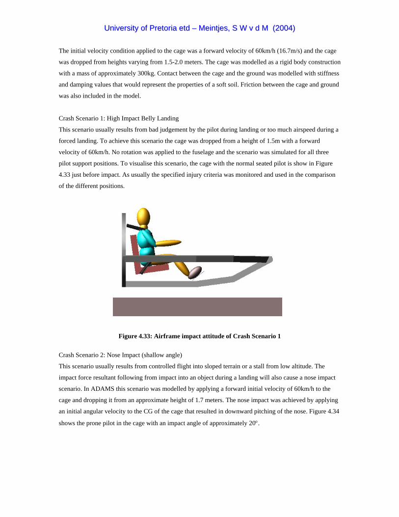
UUnniivveerrssiittyy ooff PPrreettoorriiaa eettdd –– MMeeiinnttjjeess,, SS WW vv dd MM ((22000044))
The initial velocity condition applied to the cage was a forward velocity of 60km/h (16.7m/s) and the cage
was dropped from heights varying from 1.5-2.0 meters. The cage was modelled as a rigid body construction
with a mass of approximately 300kg. Contact between the cage and the ground was modelled with stiffness
and damping values that would represent the properties of a soft soil. Friction between the cage and ground
was also included in the model.
Crash Scenario 1: High Impact Belly Landing
This scenario usually results from bad judgement by the pilot during landing or too much airspeed during a
forced landing. To achieve this scenario the cage was dropped from a height of 1.5m with a forward
velocity of 60km/h. No rotation was applied to the fuselage and the scenario was simulated for all three
pilot support positions. To visualise this scenario, the cage with the normal seated pilot is show in Figure
4.33 just before impact. As usually the specified injury criteria was monitored and used in the comparison
of the different positions.
Figure 4.33: Airframe impact attitude of Crash Scenario 1
Crash Scenario 2: Nose Impact (shallow angle)
This scenario usually results from controlled flight into sloped terrain or a stall from low altitude. The
impact force resultant following from impact into an object during a landing will also cause a nose impact
scenario. In ADAMS this scenario was modelled by applying a forward initial velocity of 60km/h to the
cage and dropping it from an approximate height of 1.7 meters. The nose impact was achieved by applying
an initial angular velocity to the CG of the cage that resulted in downward pitching of the nose. Figure 4.34
shows the prone pilot in the cage with an impact angle of approximately 20°.

UUnniivveerrssiittyy ooff PPrreettoorriiaa eettdd –– MMeeiinnttjjeess,, SS WW vv dd MM ((22000044))
Figure 4.34: Airframe impact attitude of Crash Scenario 2
Crash Scenario 3: Nose Impact (steep angle)
Because of the likelihood of a nose impact crash during aircraft accidents another nose impact scenario
with a steeper impact angle was modelled as scenario 3. The same forward initial velocity condition of
60km/h was applied but the initial angular velocity around the CG was increased and the cage was dropped
from an approximate height of 2 meters. During this scenario the impact angle was increased to
approximately 40° as indicated by the cage impact attitude shown in Figure 4.35 with the supine seated
pilot.
Figure 4.35: Airframe impact attitude of Crash Scenario 3

UUnniivveerrssiittyy ooff PPrreettoorriiaa eettdd –– MMeeiinnttjjeess,, SS WW vv dd MM ((22000044))
4.6.3 Crash Test Results
During the fuselage crash tests the peak forces and accelerations on the pilots resulted from the initial
impact into the ground and were never exceeded by the response due to the fuselage dynamics. During the
crash scenarios the orientation of the spine (inline with the vertical crash load on the cage) caused exceeded
LLC values for both the normal seated and supine seated positions. This was however not the case for the
prone position and this can be attributed to the transverse application of the crash load to the spine as
explained previously. Due to the absence of the cockpit parts like the instrument panel and the controls, no
secondary head impact occurred during the fuselage crash test. This implied that the HIC values were low
for all three the positions.
As explained in Chapter 2.6 the Nij value is evaluated by considering a combination of neck axial force and
bending moment. On evaluation of these forces and moments it seemed that the neck tension force was
constantly the highest in the case of the prone position. Although the prone pilot never exceeded the
criterion, it resulted in high values during all three scenarios. The reason for these high neck tensions could
be explained by the fact that the upper body was restrained by the shoulder straps but the head was still free
to displace forward therefore pulling on the neck.
This is actually exactly the same scenario that was obtained with the second prone position restraint
concept during the sled tests where the unbalanced pelvic and shoulder strap restraint caused a huge tension
force in the spine. Although Nij was not exceeded, the values were on the limit and the added mass of a
helmet worn by the pilot might cause a problem. Dynamic overshoot of the pilot’s head during the high
impact angle of Crash Scenario 3 resulted in a high Nij value for the normal seated pilot. The results of the
three specified injury criteria for the fuselage crash tests are contained in Table 4.3. Graphs containing the
neck axial force and bending moment for each scenario and an example calculation of Nij were included in
Appendix E. The value for Nij was calculated at each point in time but only the peak value was used for
comparison. The values used in the evaluation of the worst case Nij for all the analysis are listed in Table
E1.

UUnniivveerrssiittyy ooff PPrreettoorriiaa eettdd –– MMeeiinnttjjeess,, SS WW vv dd MM ((22000044))
Table 4.3: Fuselage crash tests injury criteria results
Analysis Pilot Position Injury Criteria (IC) IC exceeded Best Performance
LLC<6700 HIC<1000 Nij<1.0 LLC HIC Nij Scenario 1 Normal Seated 7619 18.12 0.673 1
Prone Seated 673 12.37 0.808 0 Prone Prone Supine Seated 8783 25.03 0.377 1 Supine
Scenario 2 Normal Seated 7921 2.78 0.652 1 Normal Prone Seated 3549 5.93 0.708 0 Prone Supine Seated 9490 4.77 0.378 1 Supine
Scenario 3 Normal Seated 7754 4.52 0.940 1 Normal Prone Seated 2203 14.64 0.943 0 Prone Supine Seated 10305 8.47 0.459 1 Supine
4.6.4 Conclusion
Spinal injury in the normal seated and supine seated position due to vertical crash loads seemed to be the
major problem during the fuselage crash tests. This also explains the huge amount of research into load
limiting crew seats found in the literature. The head injury criteria values for these analyses were low due
to the clean environment provided by the fuselage cage structure. As with the sled test analyses the prone
position had a small flailing envelope, which could be attributed to the passive torso restraint and the chin
rest. As a result of forward displacement of the head in the prone position the neck injury criteria values
were high in comparison and sometimes on the limit.
The injury criteria comparison resulted in the following scores. Both the normal seated and supine seated
positions exceeded three of the possible nine injury criteria and therefore receive a score of 6/9. The prone
position scored a perfect 9/9. The title of best performance in a specific injury criterion during the fuselage
crash tests was awarded twice to the normal seated position and four times to the prone position. The
supine position received this title for a competitive three times. These scores indicate that the prone
position proposal performed best during the fuselage crash test comparison.

UUnniivveerrssiittyy ooff PPrreettoorriiaa eettdd –– MMeeiinnttjjeess,, SS WW vv dd MM ((22000044))
CHAPTER 5: FINAL CONCLUSIONS AND RECOMMENDATIONS
Conclusions The question of safety of a pilot in the prone position during a crash originated long ago with the birth of
the Exulans project but was never adequately answered. Not only did this study answer this question but it
also shed more light on the whole subject of pilot protection in light aircraft. Crashworthiness are receiving
more and more attention during the design of modern aircraft structures and therefore the results of this
study would be implemented during the design of the fuselage and pilot protection system of Exulans II.
The literature study revealed that crash survivability is achieved through a combination of five design
factors described by the acronym CREEP. These design criteria require the provision of a container that
would maintain a living space to the occupant during a crash and sufficient restraint applied to appropriate
portions of the body. It also suggested that a clean environment should be provided inside the cockpit with
specific attention to the volumes through which unrestraint portions of the body might travel during a crash.
Through the implementation of energy absorbing materials and mechanisms in the airframe design, crash
forces could be attenuated to tolerable levels during high energy impact scenarios. The literature study
further revealed that the majority of aviation fatalities occur post impact. The post-crash design factor takes
this fact into consideration when it requires fast and easy evacuation from the fuselage even if damage was
inflicted during the crash.
From human impact tolerance limits it was suspected that a pilot could obtain higher crash survivability if
supported in the prone position. This statement was further investigated and proved during the dynamic
analysis of this study. It was indicated that the prone position could offer better protection to injury if
certain guidelines during the support and restraint method were followed.
In comparison with the normal seated and supine seated positions a pilot in the prone position would be
exposed to much lower spinal compression forces due to the orientation of the body with respect to a crash
load with both vertical and horizontal components. During the dynamic sled test analysis it was however
found that this argument could not be presented in the case of a frontal impact and different restraint
concepts were evaluated to improve this drawback in the prone position. The results of the different prone
concepts indicated that spinal compression during the frontal impact case could be limited if adequate
pelvic restraint was provided. On the contrary, if the pelvis was restrained adequately but not with
sufficient upper body restraint a huge tension force was induced in the spine. When analyzing the final
prone support-restraint proposal, it was however discovered that a good balance between the two restraint
systems could result in acceptable spinal loads.

UUnniivveerrssiittyy ooff PPrreettoorriiaa eettdd –– MMeeiinnttjjeess,, SS WW vv dd MM ((22000044))
The dynamic analysis also indicated that the passive torso restraint supplied by the chest support limited the
dynamic overshoot of the head and resulted in a small flailing envelope for the prone position. It was also
discovered that due to the same explanation provided for the reason of the huge tension force induced in the
spine during the frontal impact test sled simulation, the neck of the prone pilot was also exposed to rather
large tension forces. These tension forces produced neck injury criteria values on the limit and might be
unacceptable with the inclusion of a helmet.
It was also discovered that dynamic overshoot of the head and extension of the neck of the pilot in the
prone position was limited by the inclusion of a chin rest. The chin rest did however induce an additional
injury mechanism to the jaw but due to the high tolerance of the mandible and the addition of a helmet
serious injury was assumed to be unlikely. This subject is however recommended for further investigation.
From the results of the dynamic analysis it is suspected that additional head restraint would result in a much
higher crash survival rate for al three pilot positions. Whether this would be possible to accomplish without
restricting the necessary freedom of the pilot’s head is still a topic that needs further investigation.
Connecting the helmet to the existing harness system of the prone positioned pilot will go a long way to
alleviate these problems without restricting the head’s freedom of movement. A similar system called the
HANS (Head and Neck Support) is currently used by Formula 1 racing drivers. In this system the driver’s
helmet is loosely connected to a yoke through several tethers ensuring free movement of the head. The
yoke is on its turn fixed to the torso by belts thus providing helmet restraint relative to the torso. According
to Wright (2000) frontal impact tests with a Hybrid III ATD wearing the HANS system produced similar
results as that with an airbag system.
Recommendations Although some of the recommendations were not directly derived from the analysis results, they were
included due to their relevance to the Exulans project. The consideration of the five CREEP design factors
during a fuselage design was strongly emphasized throughout the literature study and therefore the first
recommendation is to structure the design of the Exulans II fuselage according to these factors. This calls
for the following:
Container
• The container should be designed for a 40g ultimate load
• To achieve a very strong light-weight construction the use of composite materials are recommended
• Provide a structure that would deflect wires from fences and electrical cables away from the pilot
• Provide roll-over protection
UUnniivveerrssiittyy ooff PPrreettoorriiaa eettdd –– MMeeiinnttjjeess,, SS WW vv dd MM ((22000044))
• Due to the fact that head injury often result in aviation fatalities it is recommended that the head should
be contained in a helmet
Restraint
• Support the Exulans II pilot in the prone position
• Provide passive torso restraint
• Use Nylon webbing with a minimum width of 50mm and a minimum thickness of 1.5mm.
• Three restraining concepts for the prone pilot were evaluated during the sled test analysis. The best
results were obtained with restraint concept 3 and is therefore recommended for use in the Exulans II
pilot protection system
• For added comfort and limited neck flexion a chin rest is recommended
• Additional head restraint is recommended to limit dynamic overshoot and neck injury
Energy Absorption
• The collapsible landing skid should be used as the primary energy absorbing mechanism
• The energy absorbing element used in the collapsible landing skid should be cheap, light and easy
replaceable. A kinetic rope or strap is recommended
• An energy absorbing mechanism or material should be used between the pilots chest support and the
fuselage
• Due to the ultra-light construction of Exulans II it is possible and recommended to equip the fuselage
with a ballistic parachute
• Equip the pilot with a parachute
Environment
• Line the inside of the fuselage structure with kevlar fiber to contain fracturing of structural elements
• Provide a soft energy-absorbing material lining at potential impact surfaces
• Avoid the use of cables and push-rods close to the pilot
Post-Crash Factors
• Design the fuselage back part to be detachable for fast and easy escape from the cockpit
• Provide a means for a midair bailout
• Make the fuselage floatable on water
• Make the pilot accessible from outside
UUnniivveerrssiittyy ooff PPrreettoorriiaa eettdd –– MMeeiinnttjjeess,, SS WW vv dd MM ((22000044))
Recommendations for Future Work
• Perform the crash test analysis with the prone pilot in the Exulans II fuselage with the recommended
energy absorbing mechanisms.
• Investigate the crash response in different prone body positions
• Investigate additional jaw injury mechanism due to impact into chin rest
• Investigate the HANS system
• Perform a finite element fuselage crash test analysis that would include fuselage deformation
• Optimize the energy absorbing mechanisms by investigating different available energy absorbing
materials
• Perform an impact experiment using a Hybrid III ATD and a prototype Exulans II fuselage
In the fuselage crash test analysis the airframe containing a pilot in a specific support restraint method was
supplied with a forward velocity and dropped from a specific height. During these analyses an idea for
evaluating the crash forces on the airframe during a survivable crash was conceived and the author would
like to propose this idea for use in the design of the Exulans II fuselage. The idea involves the use of
ADAMS as a design tool and basically states that the forward velocity and initial height components could
be converted into an energy value.
With an ADAMS model of the Exulans II fuselage and the proposed pilot protection system, the energy of
the crash could systematically be increased while injury criteria are monitored on the pilot. The moment
when the injury criteria are exceeded the crash would no longer be survivable and integrity of the structure
beyond this point would be useless. At this moment the forces on the airframe could be retrieved from
ADAMS and used as input design criteria. This process could be repeated for different crash scenarios to
obtain the worst case scenario. It is however realized that the feasibility of the resulting design would be
determined by the strict weight requirements set by the Exulans II project.

UUnniivveerrssiittyy ooff PPrreettoorriiaa eettdd –– MMeeiinnttjjeess,, SS WW vv dd MM ((22000044))
REFERENCES
ADVISORY CIRCULAR. 1985. Injury Criteria for Human Exposure to Impact. U.S Department of
Transport, Federal Aviation Administration. Advisory Circular AC No 21-22.
ADVISORY CIRCULAR. 1993. Shoulder Harness-Safety Belt Installations. U.S Department of Transport,
Federal Aviation Administration. Advisory Circular AC No 21-34.
BRADSHAW, G. Wright, S. 1996. Wright Brothers History, First Flight,1903.
http://www.wam.umd.edu/~stwright/WrBr/wrights/1903.html Access: 17 September, 2003
CAVANAUGH, J. 2000. The Biomechanics of Thoracic Trauma. Bioengineering Center. BME 7160.
Wayne State University.
COUTO, G. 1999. The Arizona Hang Glider Association Photo Gallery. http://www.ahga.org/cgi-
bin/photo.cgi?/gallery/hg0037.jpg Access 28 October, 2003
DAVIDSON, B. 1994. Crash Survivability, Improving Your Odds.
EPPINGER, R. Sun, E. Bandak, F. Haffner, M. Khaewpong, N. Maltese, M. Kuppa, S. Nguyen, T.
Takhounts, E. Tannous, R. Zhang, A. and Saul, R. 1999. Development of Improved Injury Criteria for the
Assessment of Advanced Automotive Restraint Systems – II. National Highway Traffic Safety
Administration. Final Rule Docket NHTSA-00-7013. Washington D.C.
EURONCAP. 1997. http://www.euroncap.com/tests.htm Access: 28 April 2003.
FAR. 1997. Part 23-Airworthiness Standards: Normal, Utility, Acrobatic, and Commuter Category
Airplanes. Federal Register.
FARLEY, G.L. 1983. Energy Absorption of Composite Materials. Journal of Composite Materials, Vol 17,
May 1983, Pp 267-279.
GFA. The Gliding Federation of Australia. http://www.gfa.org.au/Gallery/index4.htm Access: 28 October,
2003
GM. Protecting Occupants http://www.gm.com/company/safety/protect_occupants/dummies/index.html
Access: 15 September, 2003

UUnniivveerrssiittyy ooff PPrreettoorriiaa eettdd –– MMeeiinnttjjeess,, SS WW vv dd MM ((22000044))
HANIQUE, M. 2002. The Mock-up of the Fuselage of Exulans II. Bachelors Degree in Mechanical
Engineering. Fontys Hogescholen, Eindhoven.
JAR-22. 2001. JAR-22: Sailplanes and Powered Sailplanes. Joint Aviation Authorities. The Netherlands.
JAR-23. 2001. JAR-23: Normal, Utility, Aerobatic, and Commuter Category Aeroplanes. Joint Aviation
Authorities. The Netherlands.
JAR-VLA. 2001. JAR-VLA: Very Light Aeroplanes. Joint Aviation Authorities. The Netherlands.
LABUN, L.C. and Rapaport, M. 1994. A Third Generation Energy Absorber for Crash Attenuating
Helicopter Seating. Proceedings-50th Annual American Helicopter Society Forum, Vol 1, May 1994, pp
521-535.
Luftfahrt International, 1975. Berlin B9 Experimental Aircraft.
http://www.luft46.com/prototyp/berlin9.html Access: 18 September, 2003
McCORMICK, B.W. 1979. Aerodynamics, Aeronautics, and Flight Mechanics. 1st ed. John Wiley & Sons,
Inc. Canada.
MECHANICAL DYNAMICS INC. ADAMS Technical Manual Version 12.0
MECHANICAL DYNAMICS INC. 2002. FIGURE HUMAN MODELLER Technical Manual Version 4.0.
MEINTJES, S.W. 1999. Mock-up of Exulans II Cockpit. B. Engineer Mechanical. University of Pretoria,
Pretoria.
NASA History Office. 1958. History of Research in Space Biology and Biodynamics. Holloman Air Force
Base, New Mexico.
Naval Aerospace Medical Institute. 1991. United States Naval Flight Surgeon’s Manual. 3rd ed. The
Society of United States Naval Flight Surgeons.
NHTSA. Pedestrian and Applied biomechanics http://www-
nrd.nhtsa.dot.gov/vrtc/bio/adult/hybIII50dat.htm Access: 28 April, 2003.

UUnniivveerrssiittyy ooff PPrreettoorriiaa eettdd –– MMeeiinnttjjeess,, SS WW vv dd MM ((22000044))
NICHOLSON, C.R. and Chapman, H. The Dynamic Crashworthiness Testing of the GA-200 Seat and
Restraint System to FAR 23.562. Proceedings of the 5th Australian Aeronautical Conference, Part 1 of 2, pp
273-276.
TESTI, M. 1998. MasterBlaster Aircraft Home Page.
http://digilander.libero.it/karenfuxia/masterblaster.htm Access: 17 September, 2003
RAF MUSEUM. Gloster Meteor F8 Prone Position. http://www.rafmuseum.org.uk/gloster-meteor-f8-
prone-position.htm Access: 16 September, 2003.
RAPAPORT, M.B. Yeiser, C.W. and Oslon, M.B. 1995. Performance Assessment of the V-22 Aircraft
Crashworthy Crew Seat With Various Size and Gender Aircrew Using the Articulated Total Body (ATB)
Computer Simulation Model. Proceedings-33rd Annual SAFE Symposium, pp 279-304.
RFRL, Raspet Flight Research Laboratory, Department of Aerospace Engineering, Mississippi State
University. History: Horten Ho IV Flying Wing. http://www.ae.msstate.edu/rfrl/pages/horten.html Access:
18 September, 2003
RICHARDS, M.K. and Podob, R. 1997. Development of an Advanced Energy Absorber. Proceedings-35th
Annual SAFE symposium, pp 321-327.
SIMULA INCORPORATED. Tempe, Arizona. 1980. Aircraft Crash Survival Design Guide. Volume IV-
Aircraft Seats, Restraints, Litters, and Padding. U.S. Department of Commerce, National Technical
Information Service.
The Naval Flight Surgeon’s Pocket Reference to Aircraft Mishap Investigation. 1995. 4th ed. The Society of
United States Naval Flight Surgeons.
VALENCIA. 2003. Superbike Photo Gallery.
http://www.superbike.it/multimedia.asp?p_Anno=2003&p_S_Campionato=SBK&p_Tab=2&p_Round=ES
P Access: 28 October, 2003
WINKELMAN, K.L. and Laananen, D.H. 1996. Analysis of Energy-Absorbing Seat Configurations.
Proceedings-52nd Annual American Helicopter Society Forum, June, pp 1319-1323.
WOOD, R.H. and Sweginnis, R.W. 1996. Aircraft Accident Investigation.

UUnniivveerrssiittyy ooff PPrreettoorriiaa eettdd –– MMeeiinnttjjeess,, SS WW vv dd MM ((22000044))
WRIGHT, P. 2000. Technical: Head and Neck Support (HANS). http://www.grandprix.com/ft/ft00358.html
Access: 29 October, 2003
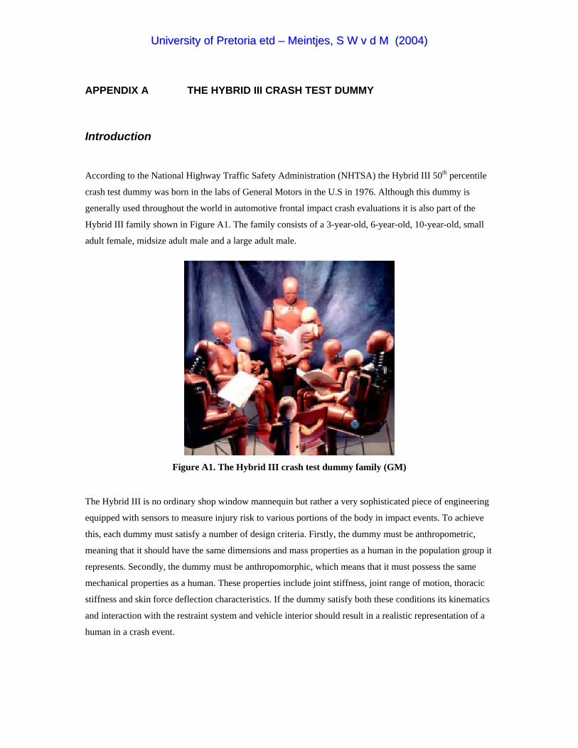
UUnniivveerrssiittyy ooff PPrreettoorriiaa eettdd –– MMeeiinnttjjeess,, SS WW vv dd MM ((22000044))
APPENDIX A THE HYBRID III CRASH TEST DUMMY
Introduction
According to the National Highway Traffic Safety Administration (NHTSA) the Hybrid III 50th percentile
crash test dummy was born in the labs of General Motors in the U.S in 1976. Although this dummy is
generally used throughout the world in automotive frontal impact crash evaluations it is also part of the
Hybrid III family shown in Figure A1. The family consists of a 3-year-old, 6-year-old, 10-year-old, small
adult female, midsize adult male and a large adult male.
Figure A1. The Hybrid III crash test dummy family (GM)
The Hybrid III is no ordinary shop window mannequin but rather a very sophisticated piece of engineering
equipped with sensors to measure injury risk to various portions of the body in impact events. To achieve
this, each dummy must satisfy a number of design criteria. Firstly, the dummy must be anthropometric,
meaning that it should have the same dimensions and mass properties as a human in the population group it
represents. Secondly, the dummy must be anthropomorphic, which means that it must possess the same
mechanical properties as a human. These properties include joint stiffness, joint range of motion, thoracic
stiffness and skin force deflection characteristics. If the dummy satisfy both these conditions its kinematics
and interaction with the restraint system and vehicle interior should result in a realistic representation of a
human in a crash event.
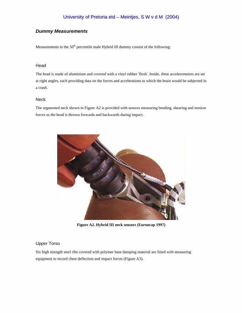
UUnniivveerrssiittyy ooff PPrreettoorriiaa eettdd –– MMeeiinnttjjeess,, SS WW vv dd MM ((22000044))
Dummy Measurements
Measurements in the 50th percentile male Hybrid III dummy consist of the following:
Head
The head is made of aluminium and covered with a vinyl rubber 'flesh'. Inside, three accelerometers are set
at right angles, each providing data on the forces and accelerations to which the brain would be subjected in
a crash.
Neck
The segmented neck shown in Figure A2 is provided with sensors measuring bending, shearing and tension
forces as the head is thrown forwards and backwards during impact.
Figure A2. Hybrid III neck sensors (Euroncap 1997)
Upper Torso
Six high strength steel ribs covered with polymer base damping material are fitted with measuring
equipment to record chest deflection and impact forces (Figure A3).

UUnniivveerrssiittyy ooff PPrreettoorriiaa eettdd –– MMeeiinnttjjeess,, SS WW vv dd MM ((22000044))
Figure A3. Steel ribs with measuring equipment in upper torso (Euroncap 1997)
Lower Torso
The lower torso consist of a curved cylindrical rubber lumber spine, which mounts to the pelvis through a
lumber load cell, which provides lumber load information.
Upper Leg, Lower Leg, Feet and Ankles
The ball-jointed femur attachments in the pelvis carry bump stops to reproduce the human leg to hip
moment/rotation characteristics. The femur, tibia and ankle can be instrumented to predict bone fracture
and the knee can evaluate tibia to femur ligament injury. The foot and ankle simulate heel compression and
ankle range of motion.
The following tables contain more specifications on the Hybrid III family. In Table A1 the mass, sitting
height and stature of the different family members are listed. Table A2 contains the segment masses of the
50th percentile dummy. The major dimensions of the 50th percentile male Hybrid III are given in Table A3
and Table A4 lists the instrumentation used in the 50th percentile male Hybrid III.
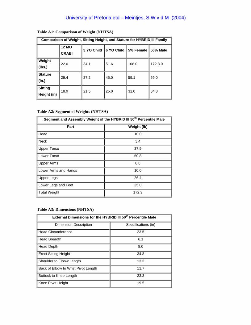
UUnniivveerrssiittyy ooff PPrreettoorriiaa eettdd –– MMeeiinnttjjeess,, SS WW vv dd MM ((22000044))
Table A1: Comparison of Weight (NHTSA)
Comparison of Weight, Sitting Height, and Stature for HYBRID III Family
12 MO CRABI
3 YO Child 6 YO Child 5% Female 50% Male
Weight (lbs.)
22.0 34.1 51.6 108.0 172.3.0
Stature (in.)
29.4 37.2 45.0 59.1 69.0
Sitting Height (in)
18.9 21.5 25.0 31.0 34.8
Table A2: Segmented Weights (NHTSA)
Segment and Assembly Weight of the HYBRID III 50 Percentile Maleth
Part Weight (lb)
Head 10.0
Neck 3.4
Upper Torso 37.9
Lower Torso 50.8
Upper Arms 8.8
Lower Arms and Hands 10.0
Upper Legs 26.4
Lower Legs and Feet 25.0
Total Weight 172.3
Table A3: Dimensions (NHTSA)
External Dimensions for the HYBRID III 50 Percentile Maleth
Dimension Description Specifications (in)
Head Circumference 23.5
Head Breadth 6.1
Head Depth 8.0
Erect Sitting Height 34.8
Shoulder to Elbow Length 13.3
Back of Elbow to Wrist Pivot Length 11.7
Buttock to Knee Length 23.3
Knee Pivot Height 19.5
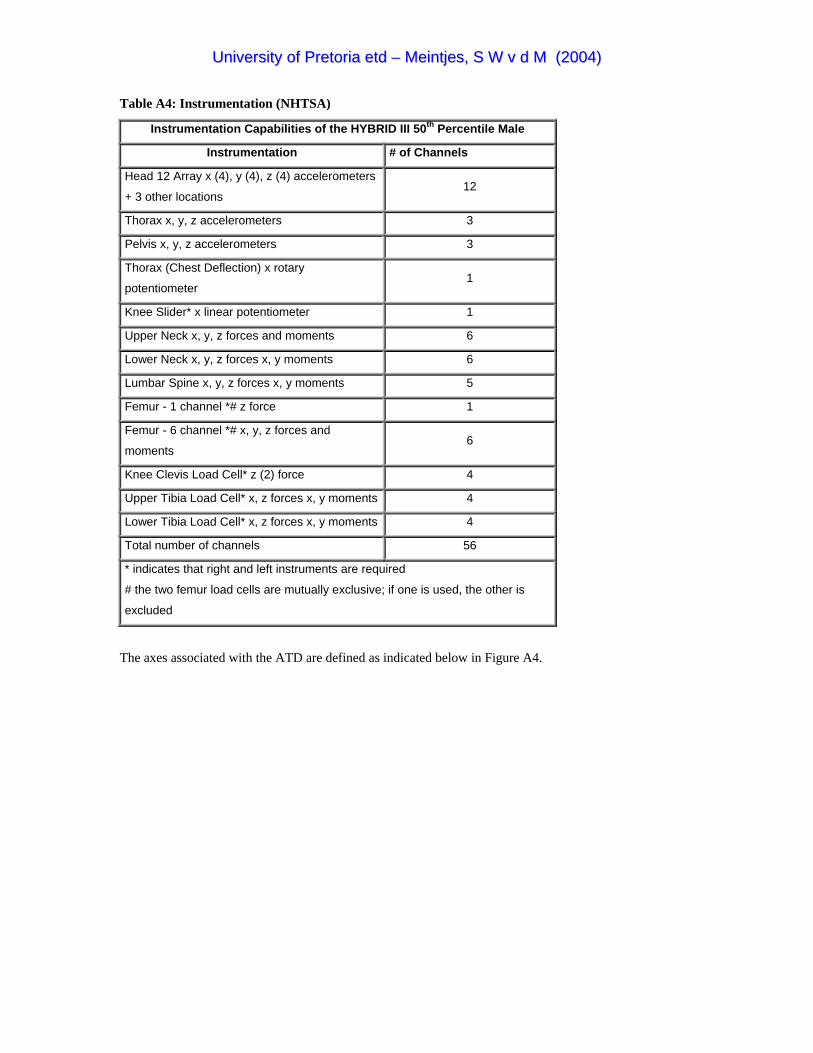
UUnniivveerrssiittyy ooff PPrreettoorriiaa eettdd –– MMeeiinnttjjeess,, SS WW vv dd MM ((22000044))
Table A4: Instrumentation (NHTSA)
Instrumentation Capabilities of the HYBRID III 50 Percentile Maleth
Instrumentation # of Channels
Head 12 Array x (4), y (4), z (4) accelerometers
+ 3 other locations 12
Thorax x, y, z accelerometers 3
Pelvis x, y, z accelerometers 3
Thorax (Chest Deflection) x rotary
potentiometer 1
Knee Slider* x linear potentiometer 1
Upper Neck x, y, z forces and moments 6
Lower Neck x, y, z forces x, y moments 6
Lumbar Spine x, y, z forces x, y moments 5
Femur - 1 channel *# z force 1
Femur - 6 channel *# x, y, z forces and
moments 6
Knee Clevis Load Cell* z (2) force 4
Upper Tibia Load Cell* x, z forces x, y moments 4
Lower Tibia Load Cell* x, z forces x, y moments 4
Total number of channels 56
* indicates that right and left instruments are required
# the two femur load cells are mutually exclusive; if one is used, the other is
excluded
The axes associated with the ATD are defined as indicated below in Figure A4.

UUnniivveerrssiittyy ooff PPrreettoorriiaa eettdd –– MMeeiinnttjjeess,, SS WW vv dd MM ((22000044))
Figure A4. ATD axes definition

UUnniivveerrssiittyy ooff PPrreettoorriiaa eettdd –– MMeeiinnttjjeess,, SS WW vv dd MM ((22000044))
APPENDIX B SHOULDER HARNESS AND SAFETY BELT INSTALLATIONS
Experience
According to the Advisory Circular (1993) experience has shown that the best safety mechanism that a
driver and passengers of an automobile has, is the conventional seat belt. Statistics indicate that an airbag,
also known as a Supplementary Restraint System (SRS), is only effective if the seat belt is also worn. Of
more relevance is that aviation accident experience has provided substantial evidence that the use of a
shoulder harness in conjunction with a safety belt can reduce serious injury to the head, neck and upper
torso of aircraft occupants. Experience also indicated that the correct application of a shoulder harness and
safety belt has the potential to reduce fatalities of occupants involved in otherwise survivable accidents.
The same experience has shown that installation geometry, attachment techniques and the cabin area
surrounding the seat influence the shoulder harness-safety belt combination that should be selected and the
effectiveness of that restraint system.
Most aircraft occupants generally accept the use of a lap belt for restraint during turbulence, aerobatics
manoeuvres and agricultural flying. A shoulder harness is however generally associated with the relatively
rear occurrence of an accident and it is often heard that a shoulder harness is cumbersome, unwieldy, hot
and uncomfortable. Such objections for not installing and using a shoulder harness should be dispelled in
view of the benefits gained from using a correctly designed and installed shoulder harness-safety belt
system. These benefits range from the prevention of serious head, neck and upper torso injuries in minor
accidents to the prevention of irreversible or fatal injuries in more severe accidents.
Shoulder Harness Configurations
Shoulder harness assemblies are categorised as single shoulder belt assemblies and dual shoulder belt
assemblies. The single shoulder belt configuration is normally arranged diagonally across the occupant’s
chest and is also referred to as a 3-point restraint system (Figure B1). The dual shoulder belt assembly is a
symmetrical arrangement of two belts with one belt passing over each of the occupant’s shoulders. This
arrangement is frequently referred to as a 4-point (Figure B2) or a 5-point (Figure B3) restraint system if a
negative-G strap is used. Shoulder harness systems should be designed to meet the requirements specified
by the ultimate inertia loads resulting from emergency landing conditions specified in the JAR or the torso
restraint system Technical Standard Order (TSO) C114.

UUnniivveerrssiittyy ooff PPrreettoorriiaa eettdd –– MMeeiinnttjjeess,, SS WW vv dd MM ((22000044))
Figure B1: Single strap 3-point restraint Figure B2: Dual strap 4-point restraint
(Advisory Circular 1993) (Advisory Circular 1993)
Figure B3: Dual strap 5-point restraint (Advisory Circular 1993)
Shoulder Harness Considerations
The elements that should be considered when installing a shoulder harness restraint system are the
webbing, steel cables, energy absorbing devices and buckles. Each of these elements play an important roll
in the effectiveness of the restraint system as described in the following paragraphs.

UUnniivveerrssiittyy ooff PPrreettoorriiaa eettdd –– MMeeiinnttjjeess,, SS WW vv dd MM ((22000044))
Webbing
Webbing is the one element common to all shoulder harness installations. Webbing should be made from
synthetic materials to avoid deterioration by climate exposure. Webbing characteristics to consider are the
width, thickness, weave and elasticity.
Webbing Width
Technical Standard Order (TSO) C114, torso restraint systems, allows a minimum webbing width of 1.8
inches (45mm). The majority of shoulder harness-safety belt systems designed for civil aircraft use nominal
2.0 inches (50mm) wide webbing. Webbing widths of 2.25 – 3 inch and associated hardware are also
available for special applications. The correct hardware fittings should be used with the appropriate
webbing width to avoid wear and cutting of the webbing under strain.
Webbing Thickness
It is again important to match the hardware to the webbing thickness. Some hardware elements such as
retractors and manual length adjusters are sensitive to webbing thickness. Nominal webbing thickness of
1.0 and 1.5 millimetres is common in civil aircraft restraint systems but thicker webbing is available for
special applications. The thickness of the webbing contributes to the maintenance of the contact between
webbing and occupants under load.
Webbing Weave
Herringbone weave is used in most new webbing designs. Hardware should be matched to the correct type
of weave because incorrect hardware to webbing adoption could lead to excessive slippage under loads.
Webbing Elasticity
The webbing commonly used in safety belt designs is an elastic material. Nylon is the most common and
the 2.0-inch webbing permits a 17 to 20% stretch under a tensile load of 2500 pounds with the herringbone
weave. Dacron 2.0-inch webbing with the herringbone weave exhibits an elasticity of 8% under a 2500-
pound tensile load. If limited space for occupant displacement is available in the aircraft cabin, substantial
elongation of the webbing should not be allowed.

UUnniivveerrssiittyy ooff PPrreettoorriiaa eettdd –– MMeeiinnttjjeess,, SS WW vv dd MM ((22000044))
Cables
The use of steel aircraft cable offers a means of reducing occupant displacement due to unwanted webbing
elongation and it is also used to extend belts to suitable attachment points. It is however important to take
the necessary precautions when using steel cable and they include the following.
• Use cable flexible in bending to avoid fatigue failure due to flexing
• Avoid sharp bends of the cable. A bend radius of at least 4 times the diameter is recommended
• Selection of any cable clevises needs careful attention
Energy Absorbing Devices
The use of energy absorbing devises in the webbing of the shoulder harness-safety belt chain is not
recommended. This is primarily recommended due to the increased potential for secondary occupant
impact. Insufficient torso restraint that could lead to head injury should be expected when energy-absorbing
devices are used in the webbing. Energy absorbing mechanisms should be incorporated into the aircraft
structure or seat and webbing elongation should be limited.
Buckles
Buckles provide the basic means of securing the various segments of a shoulder harness-safety belt system
around the occupant and also allow easy and quick release of the system. According to the FAR metal-to-
metal coupling provide improved security and reliability over any method of coupling which rely on
clamping of the webbing. The release mechanism of the buckle should be designed to minimise the
potential for inadvertent release by the occupant or premature release by inertia forces acting on it. It
should also be designed for fast and easy release by one finger after an accident.
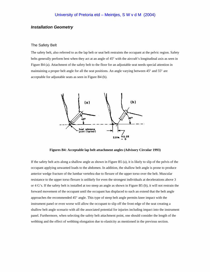
UUnniivveerrssiittyy ooff PPrreettoorriiaa eettdd –– MMeeiinnttjjeess,, SS WW vv dd MM ((22000044))
Installation Geometry
The Safety Belt
The safety belt, also referred to as the lap belt or seat belt restraints the occupant at the pelvic region. Safety
belts generally perform best when they act at an angle of 45° with the aircraft’s longitudinal axis as seen in
Figure B4 (a). Attachment of the safety belt to the floor for an adjustable seat needs special attention in
maintaining a proper belt angle for all the seat positions. An angle varying between 45° and 55° are
acceptable for adjustable seats as seen in Figure B4 (b).
Figures B4: Acceptable lap belt attachment angles (Advisory Circular 1993)
If the safety belt acts along a shallow angle as shown in Figure B5 (a), it is likely to slip of the pelvis of the
occupant applying unwanted loads to the abdomen. In addition, the shallow belt angle is prone to produce
anterior wedge fracture of the lumbar vertebra due to flexure of the upper torso over the belt. Muscular
resistance to the upper torso flexure is unlikely for even the strongest individuals at decelerations above 3
or 4 G’s. If the safety belt is installed at too steep an angle as shown in Figure B5 (b), it will not restrain the
forward movement of the occupant until the occupant has displaced to such an extend that the belt angle
approaches the recommended 45° angle. This type of steep belt angle permits knee impact with the
instrument panel or even worse will allow the occupant to slip off the front edge of the seat creating a
shallow belt angle scenario with all the associated potential for injuries including impact into the instrument
panel. Furthermore, when selecting the safety belt attachment point, one should consider the length of the
webbing and the effect of webbing elongation due to elasticity as mentioned in the previous section.
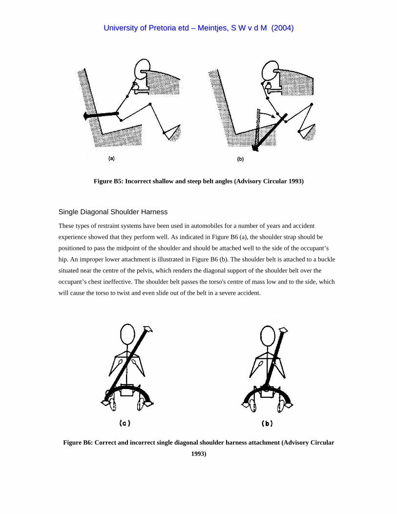
UUnniivveerrssiittyy ooff PPrreettoorriiaa eettdd –– MMeeiinnttjjeess,, SS WW vv dd MM ((22000044))
Figure B5: Incorrect shallow and steep belt angles (Advisory Circular 1993)
Single Diagonal Shoulder Harness
These types of restraint systems have been used in automobiles for a number of years and accident
experience showed that they perform well. As indicated in Figure B6 (a), the shoulder strap should be
positioned to pass the midpoint of the shoulder and should be attached well to the side of the occupant’s
hip. An improper lower attachment is illustrated in Figure B6 (b). The shoulder belt is attached to a buckle
situated near the centre of the pelvis, which renders the diagonal support of the shoulder belt over the
occupant’s chest ineffective. The shoulder belt passes the torso's centre of mass low and to the side, which
will cause the torso to twist and even slide out of the belt in a severe accident.
Figure B6: Correct and incorrect single diagonal shoulder harness attachment (Advisory Circular
1993)
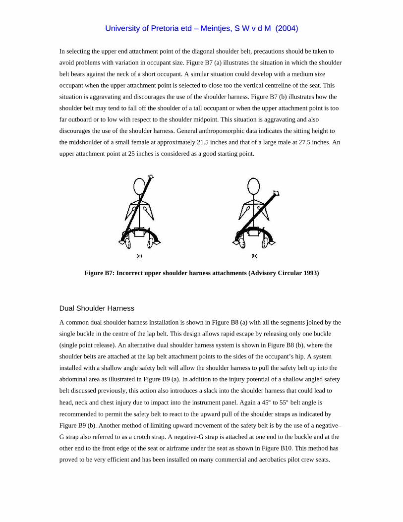
UUnniivveerrssiittyy ooff PPrreettoorriiaa eettdd –– MMeeiinnttjjeess,, SS WW vv dd MM ((22000044))
In selecting the upper end attachment point of the diagonal shoulder belt, precautions should be taken to
avoid problems with variation in occupant size. Figure B7 (a) illustrates the situation in which the shoulder
belt bears against the neck of a short occupant. A similar situation could develop with a medium size
occupant when the upper attachment point is selected to close too the vertical centreline of the seat. This
situation is aggravating and discourages the use of the shoulder harness. Figure B7 (b) illustrates how the
shoulder belt may tend to fall off the shoulder of a tall occupant or when the upper attachment point is too
far outboard or to low with respect to the shoulder midpoint. This situation is aggravating and also
discourages the use of the shoulder harness. General anthropomorphic data indicates the sitting height to
the midshoulder of a small female at approximately 21.5 inches and that of a large male at 27.5 inches. An
upper attachment point at 25 inches is considered as a good starting point.
Figure B7: Incorrect upper shoulder harness attachments (Advisory Circular 1993)
Dual Shoulder Harness
A common dual shoulder harness installation is shown in Figure B8 (a) with all the segments joined by the
single buckle in the centre of the lap belt. This design allows rapid escape by releasing only one buckle
(single point release). An alternative dual shoulder harness system is shown in Figure B8 (b), where the
shoulder belts are attached at the lap belt attachment points to the sides of the occupant’s hip. A system
installed with a shallow angle safety belt will allow the shoulder harness to pull the safety belt up into the
abdominal area as illustrated in Figure B9 (a). In addition to the injury potential of a shallow angled safety
belt discussed previously, this action also introduces a slack into the shoulder harness that could lead to
head, neck and chest injury due to impact into the instrument panel. Again a 45° to 55° belt angle is
recommended to permit the safety belt to react to the upward pull of the shoulder straps as indicated by
Figure B9 (b). Another method of limiting upward movement of the safety belt is by the use of a negative–
G strap also referred to as a crotch strap. A negative-G strap is attached at one end to the buckle and at the
other end to the front edge of the seat or airframe under the seat as shown in Figure B10. This method has
proved to be very efficient and has been installed on many commercial and aerobatics pilot crew seats.
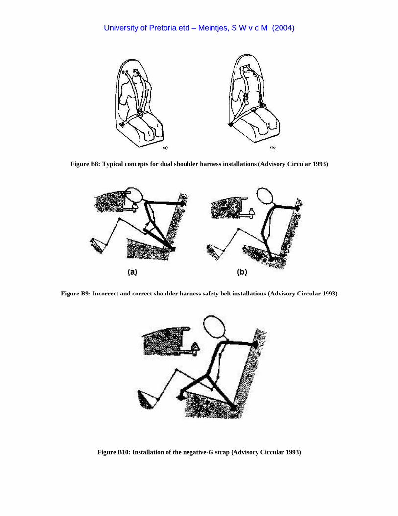
UUnniivveerrssiittyy ooff PPrreettoorriiaa eettdd –– MMeeiinnttjjeess,, SS WW vv dd MM ((22000044))
Figure B8: Typical concepts for dual shoulder harness installations (Advisory Circular 1993)
Figure B9: Incorrect and correct shoulder harness safety belt installations (Advisory Circular 1993)
Figure B10: Installation of the negative-G strap (Advisory Circular 1993)

UUnniivveerrssiittyy ooff PPrreettoorriiaa eettdd –– MMeeiinnttjjeess,, SS WW vv dd MM ((22000044))
Spinal Compression
Compression of the spinal column by both single and dual shoulder harnesses should be avoided. This can
generally be achieved by selecting the upper attachment points of the shoulder harness such that the trailing
length behind the occupant does not fall below an angle of 5° below the longitudinal tangent to the
occupant’s shoulder as indicated in Figure B11. Spinal compression is likely to occur when the upper end
of the shoulder harness is mounted below the occupant’s shoulders. This configuration, as illustrated in
Figure B12, causes the straps to pull down onto the occupant’s shoulders as forward movement is resisted.
The resultant restraint force shown in Figure B13 will place the spinal column under compression, which
will add to the stress on the vertebra due to the vertical deceleration in an accident. In addition, attaching
the upper end of the shoulder harness too high will create additional structural loads and would provide
poor restraint to forward displacement of the occupant. A maximum angle of 30° above the longitudinal
tangent to the shoulder is recommended as a guideline (refer Figure B11).
Figure B11: Acceptable range of upper attachment points (Advisory Circular 1993)

UUnniivveerrssiittyy ooff PPrreettoorriiaa eettdd –– MMeeiinnttjjeess,, SS WW vv dd MM ((22000044))
Figure B12: Compression of spine due to incorrect shoulder strap installation (Advisory Circular 1993)
Figure B13: Spinal compression due to resultant restraint force (Advisory Circular 1993)

UUnniivveerrssiittyy ooff PPrreettoorriiaa eettdd –– MMeeiinnttjjeess,, SS WW vv dd MM ((22000044))
Conclusion
The intent of the Advisory Circular (AC) was to provide guidance to achieve an effective shoulder harness-
safety belt installation in the dynamic loading environment. It is, however, recognised that compromises are
necessary due to the absence of sufficient attachment structure in some aircraft. In conclusion the most
valuable pointers retrieved from the AC concerning shoulder harness-safety belt restraint systems are listed
below.
• Width of webbing in contact with occupant, nominally 2.0 inches or more
• Minimise webbing stretch by minimising webbing length
• Use single buckle for release and escape
• Attachment range for safety belts, between 45° and 55° for all seat positions
• Webbing guides position dual shoulder straps at middle of occupant’s shoulders
• Lower attachment of single diagonal shoulder strap to the side of occupant’s hip
• Upper attachment of single diagonal strap should provide sufficient restraint for various occupant sizes
• Elevation angle range of trailing shoulder straps between 5° and 30° from longitudinal

UUnniivveerrssiittyy ooff PPrreettoorriiaa eettdd –– MMeeiinnttjjeess,, SS WW vv dd MM ((22000044))
APPENDIX C JOINT AVIATION REGULATIONS SELECTIONS
JAR-22
The Joint Aviation Regulations requirements for sailplanes and powered sailplanes are stated in JAR-22
(2001). Some of the important requirements concerning pilot protection and occupant safety were
summarised in the following paragraphs.
JAR 22.561 Emergency Landing Conditions
a) Although the sailplane may be damaged in emergency landing conditions, it must be designed to
protect the occupant under the prescribed conditions.
b) The structure must be designed to protect the occupant provided that full use is made of seat belts
and harnesses under the following conditions.
1) If the occupant experiences separately ultimate inertia forces corresponding to the
following accelerations:
Upward 4.5g
Downward 9.0g
Sideward 3.0g
Downward 4.5g
2) If an ultimate load of 6 times the weight of the sailplane acting rearwards and upwards at
an angle of 45° to the longitudinal axis of the sailplane is applied at the most suitable
forward position of the fuselage.
c) A sailplane with retractable landing gear must be designed to protect the occupant in a landing
with wheels retracted under the following conditions.
1) With a downward ultimate inertia force corresponding to an acceleration of 3g.
2) With a coefficient of friction of 0.5 at the ground.
d) The supporting structure must be designed to restrain under loads specified in sub-paragraph
(b)(1) each item of mass that could injure the occupant if it came loose in a minor crash landing.
e) For a powered sailplane with the engine located behind and above the pilot’s seat an ultimate
inertia load of 15g in the forward direction must be assumed.
JAR 22.785 Seats and Safety Harnesses
a) Each seat and supporting structure must be designed for an occupant weight in accordance with
JAR-22.25 (a)(2) and for the maximum load factors corresponding to the specified flight, ground

UUnniivveerrssiittyy ooff PPrreettoorriiaa eettdd –– MMeeiinnttjjeess,, SS WW vv dd MM ((22000044))
and emergency landing conditions prescribed by JAR 22.561. The seat and its supporting structure
must also be designed to withstand the reaction to the load specified in JAR 22.397(b).
b) The seats including the cushions may not deform to such an extend that the pilot is unable to reach
the controls safely or operate the wrong controls when subjected to the loads corresponding to
JAR 22.581 and JAR 22.583.
c) The seat design must allow the accommodation of a parachute worn by the occupant and must
allow comfortable seating weather the occupant wears a parachute or not.
d) The strength of the safety harness must not be less than that following from the ultimate loads of
the flight and ground load conditions and the emergency landing conditions according to JAR
22.561(b).
e) Safety harness installations must be designed so that the occupant is safely retained in his initial
sitting or reclining position under any acceleration occurring in operation.
f) Each seat and safety harness installation must be designed to give each occupant every reasonable
change of escaping serious injury under the conditions of JAR 22.561(b)(1).
IEM 22.785 Seats and Safety Harnesses
1) The arrangement of the safety harness installation should minimise the probability of the
occupant’s body from sliding underneath the belts or laterally when subjected to inertia loads
acting in the forward or sideward direction.
2) For semi-reclined seating positions the anchorage points of the lap belt should be located well
below and behind the H-Point at an angle between 80°±10° to the datum line through the H-Point
parallel to the longitudinal axis of the sailplane. The H-Point (Hip Point) is the pivot between the
torso centreline and the thigh centreline of the occupant.
3) The anchorage points of the shoulder belts for a 50 percentile male should be located below and
behind the pilots shoulders at an angle of 15° +2°/-0° to a line parallel to the longitudinal axis of
the sailplane. The lateral separation should not be more than 200mm (see Figure C1).
Figure C1: Lap and shoulder belt attachment points in supine position (JAR-22 2001)

UUnniivveerrssiittyy ooff PPrreettoorriiaa eettdd –– MMeeiinnttjjeess,, SS WW vv dd MM ((22000044))
JAR 22.786 Protection from Injury
a) Rigid structural members or rigidly mounted items of equipment must be padded where necessary
to protect the occupant from injury during minor crash conditions.
b) Structural members which, by the nature of their size or shape are capable of piercing the
instrument panel, must be designed or positioned such that under the conditions of JAR
22.561(b)(2) injury to occupants would be unlikely.
JAR 22.788 Headrests
a) A headrest must be provided to protect the occupant from rebound injuries in the event of a crash
landing. It must be equipped with energy absorbing padding protected against wear and
weathering encountered in normal operating conditions. Adjustable headrests must be capable of
being positioned such that the point of contact is at eye level.
b) Each headrest must be designed to minimise the possibility of entanglement with clothing or the
parachute when bailing out.
c) Each headrest must be designed for an ultimate load of at least 135daN acting normal to a vertical
plane touching the head contact point when the headrest is in its most critical position.
d) The width and design of the headrest must not restrict vision from either seat.
IEM 22.788 Headrests
a) If possible the structure of the headrest should be integrated into the backrest of the seat.
b) Each headrest should be designed that protection from injury is ensured whether the occupant
wears a parachute or not.
JAR 22.807 Emergency Exit
a) The cockpit must be so designed that unimpeded and rapid escape in emergency situations during
flight and on the ground is possible with the occupant wearing a parachute.
b) The opening or jettisoning of the canopy or emergency exit must not be prevented by the presence
of aerodynamic forces and/or by the weight of the canopy at speeds up to VDF or by jamming of
the canopy by other parts of the sailplane. The canopy or emergency attachment fittings must be
designed to permit easy jettisoning.
c) The opening system must be designed for simple and easy operation. It must function rapidly and
must also be designed for operation by each occupant strapped in his seat and from the outside of
the cockpit.
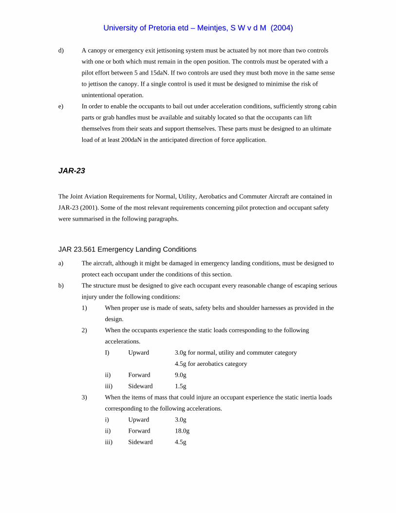
UUnniivveerrssiittyy ooff PPrreettoorriiaa eettdd –– MMeeiinnttjjeess,, SS WW vv dd MM ((22000044))
d) A canopy or emergency exit jettisoning system must be actuated by not more than two controls
with one or both which must remain in the open position. The controls must be operated with a
pilot effort between 5 and 15daN. If two controls are used they must both move in the same sense
to jettison the canopy. If a single control is used it must be designed to minimise the risk of
unintentional operation.
e) In order to enable the occupants to bail out under acceleration conditions, sufficiently strong cabin
parts or grab handles must be available and suitably located so that the occupants can lift
themselves from their seats and support themselves. These parts must be designed to an ultimate
load of at least 200daN in the anticipated direction of force application.
JAR-23
The Joint Aviation Requirements for Normal, Utility, Aerobatics and Commuter Aircraft are contained in
JAR-23 (2001). Some of the most relevant requirements concerning pilot protection and occupant safety
were summarised in the following paragraphs.
JAR 23.561 Emergency Landing Conditions
a) The aircraft, although it might be damaged in emergency landing conditions, must be designed to
protect each occupant under the conditions of this section.
b) The structure must be designed to give each occupant every reasonable change of escaping serious
injury under the following conditions:
1) When proper use is made of seats, safety belts and shoulder harnesses as provided in the
design.
2) When the occupants experience the static loads corresponding to the following
accelerations.
I) Upward 3.0g for normal, utility and commuter category
4.5g for aerobatics category
ii) Forward 9.0g
iii) Sideward 1.5g
3) When the items of mass that could injure an occupant experience the static inertia loads
corresponding to the following accelerations.
i) Upward 3.0g
ii) Forward 18.0g
iii) Sideward 4.5g

UUnniivveerrssiittyy ooff PPrreettoorriiaa eettdd –– MMeeiinnttjjeess,, SS WW vv dd MM ((22000044))
c) Each aircraft with retractable landing gear must protect the occupants in the following landing
conditions:
1) A landing with the wheels retracted.
2) A landing with moderate descent velocity.
3) Assuming a downward ultimate inertia load force of 3.0g and a coefficient of friction of
0.5 at the ground.
d) If it is not established that a turnover is unlikely during an emergency landing condition, the
structure must be designed to protect the occupants in a complete turnover as follows:
1) The likelihood of a turnover may be shown by an analysis assuming the following
conditions:
i) The most adverse combination of weight and CG position
ii) A longitudinal load factor of 9.0g
iii) A vertical load factor of 1.0g
iv) For aircraft with tricycle landing gear, the nose wheel strut failed with the nose
contacting the ground
2) An upward ultimate inertia load factor of 3.0g and a coefficient of friction of 0.5 with the
ground must be used to determine the loads on the inverted aircraft.
e) Except as provided in JAR 23.787(c), the supporting structure must be designed to restrain under
loads specified in (b)(3) each item of mass that could injure an occupant if it came loose in a
minor crash landing.
JAR 23.562 Emergency Landing Dynamic Conditions
a) Each seat/restraining system must be designed to protect each occupant in an emergency landing
under the following conditions:
1) When proper use is made of seats, safety belts and shoulder harnesses provided in the
design.
2) When the occupants is exposed to the loads resulting from the conditions prescribed in
this section.
b) Each seat/restraint system must successfully complete dynamic tests or be demonstrated by
analysis supported by dynamic tests in accordance with the following conditions. These tests must
be conducted with an Anthropomorphic Test Dummy (ATD) seated in the normal upright
position.
1) For the first test the change in velocity may not be less than 31ft per second. The
seat/restraint system must be oriented in its normal position with respect to the aircraft
but with the aircraft pitched up 60° with respect to the horizontal plane. For seat/restraint
systems installed in the first row of the aircraft, peak decelerations must occur in no more

UUnniivveerrssiittyy ooff PPrreettoorriiaa eettdd –– MMeeiinnttjjeess,, SS WW vv dd MM ((22000044))
than 0.05 seconds after impact and must reach a minimum of 19g. For all other
seat/restraint systems, peak decelerations must occur in no more than 0.06 seconds after
impact and must reach a minimum of 15g.
2) For the second test the change in velocity may not be less than 42ft per second. The
seat/restraint system must be oriented in its normal position with respect to the aircraft
with the aircraft yawed at 10°. For seat/restraint systems installed in the first row of the
aircraft, peak decelerations must occur in not more than 0.05 seconds after impact and
must reach a minimum of 26g. For all other seat/restraint systems, peak deceleration must
occur in no more than 0.06 seconds after impact and must reach a minimum of 21g.
3) To account for floor warpage the floor rails used to attach the seat/restraint system to the
airframe structure must be preloaded to misalign with each other by at least 10° vertically
(i.e. pitch out of parallel). One of the rails must be preloaded to misalign by at least 10° in
roll prior to conducting the test.
c) Compliance with the following requirements must be shown during the dynamic tests conducted
in accordance with subparagraph (b)(2).
1) The seat/restraint system must restraint the ATD although the seat/restraint system
components may experience deformation, elongation, displacement or crushing intended
as part of the design.
2) The attachment between the seat/restraint system and the test fixture must remain intact
although the seat structure may have deformed.
3) Each shoulder harness strap must remain on the ATD’s shoulder during the impact.
4) The safety belt must remain on the ATD’s pelvis during the impact.
5) The results of the dynamic tests must show that the occupant is protected from serious
head injury considering the following.
i) When head contact can occur, protection must be provided so that head impact
does not exceed a Head Injury Criteria (HIC) of 1000.
ii) The value of HIC is defined as:
Where:
t1 is the initial integration time in seconds
t2 is the final integration time in seconds
(t2 – t1) is the duration of the major head impact separated by no more than 36
milliseconds
a(t) is the resultant deceleration at the CG of the head expressed as a
multiple of g

UUnniivveerrssiittyy ooff PPrreettoorriiaa eettdd –– MMeeiinnttjjeess,, SS WW vv dd MM ((22000044))
iii) Compliance with the HIC limit must be demonstrated by measuring the head
impact during dynamic testing as prescribed in sub-paragraphs (b)(1) and (b)(2).
6) Loads in individual shoulder harness straps may not exceed 794kg. If dual straps are used
to restrain the upper torso, the total strap loads may not exceed 907kg.
7) The compression load measured between the pelvis and lumbar spine of the ATD may
not exceed 680kg.
d) An alternative approach that achieves an equivalent or greater level of occupant protection to that
required by this section may be used if substantiated on a rational basis.
JAR-VLA
The Joint Aviation Requirements for Very light Aircraft are contained in JAR-VLA (2001). Some of the
most relevant requirements concerning pilot protection and occupant safety were summarised in the
following paragraphs.
JAR-VLA 561 Emergency Landing Conditions
a) Although the aircraft may be damaged in emergency landing conditions, it must be designed to protect
the occupant under the following prescribed conditions.
b) The structure must be designed to give each occupant reasonable change of escaping serious injury
under the following conditions:
1) If proper use was made of the provided seatbelts and harnesses.
2) If the occupant experiences ultimate inertia load factors corresponding to the following
accelerations:
Upward 3.0g
Forward 9.0g
Sideward 1.5g
c) Each item of mass that could injure the occupant if it came loose must be designed according to the
loads stated above. For engines installed behind and above the occupant’s seat the engine mount and
supporting structure must be designed for an ultimate load factor of 15g.
d) The structure must be designed to protect the occupant in a complete turnover scenario under the
following conditions.
1) An upward ultimate inertia force of 3g.
2) A coefficient of friction of 0.5 at the ground.
e) Each aircraft with retractable landing gear should be designed to protect the occupant under the
following conditions.

UUnniivveerrssiittyy ooff PPrreettoorriiaa eettdd –– MMeeiinnttjjeess,, SS WW vv dd MM ((22000044))
1) A landing with wheels retracted.
2) A landing with moderate descent velocity.
3) A landing with a downward inertia load of 3g and a coefficient of friction of 0.5 at the ground.
JAR-VLA 783 Exits
a) The aircraft must be designed that unimpeded and rapid escape is possible in any normal and crash
attitude including turn over.
b) No exits may be located with respect to any propeller disc that might endanger persons using that
exit.
JAR-VLA 785 Seats, Safety belts and Harnesses
a) Each seat and its supporting structure must be designed for an occupant weighing at least 86kg
and for the maximum load factors corresponding to the flight load, ground load and emergency
landing conditions described in JAR-VLA 561.
b) Each safety belt with shoulder harness must be approved and must be equipped with a metal to
metal latching device.
c) Each pilot seat must be designed for reactions resulting from the application of the pilot forces to
the primary flight controls as described in JAR-VLA 395.
d) Proof of compliance with the strength and deformation requirements for seat installations must be
shown by one of the following:
1) Structural analysis, if the structure conforms to conventional aircraft types for which
existing methods are known.
2) A combination of structural analysis and static load tests to the limit loads.
3) Static load tests to ultimate loads.
e) Each occupant must be protected from serious head injury by a safety belt and shoulder harness
that is designed to prevent the head from contacting any injurious object.
f) Each shoulder harness installed at a pilot’s seat must allow the pilot in the seated position to
perform all functions necessary for flight operations.
g) There must be a means to secure the safety belt and shoulder harness when not in use to prevent
interference with operations and rapid egress during an emergency.
h) The seat track must be fitted with stops to prevent the seat from sliding from the tracks.
i) The cabin area surrounding each seat, within striking distance of the occupant’s head or torso must
be free of any potential injurious objects. If energy absorbing designs or devices are used to meet
this requirement they must protect the occupant against serious injury when ultimate inertia forces
as described in JAR-VLA 561 are experienced by the occupant.
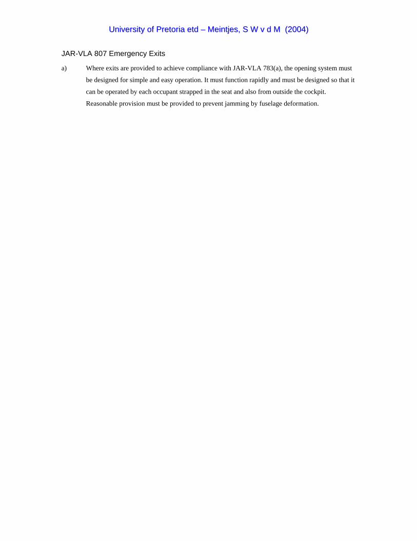
UUnniivveerrssiittyy ooff PPrreettoorriiaa eettdd –– MMeeiinnttjjeess,, SS WW vv dd MM ((22000044))
JAR-VLA 807 Emergency Exits
a) Where exits are provided to achieve compliance with JAR-VLA 783(a), the opening system must
be designed for simple and easy operation. It must function rapidly and must be designed so that it
can be operated by each occupant strapped in the seat and also from outside the cockpit.
Reasonable provision must be provided to prevent jamming by fuselage deformation.
UUnniivveerrssiittyy ooff PPrreettoorriiaa eettdd –– MMeeiinnttjjeess,, SS WW vv dd MM ((22000044))
APPENDIX D ADAMS AND FIGURE HUMAN MODELLER
ADAMS
According to Mechanical Dynamics Inc. ADAMS stands for Automatic Dynamic Analysis of Mechanical
Systems and is the world’s most widely used mechanical system simulation software. With ADAMS you
can build “virtual prototypes” on the computer and run realistic visual and mathematical simulations of
complex mechanical system. ADAMS enables one to quickly implement multiple design variations until an
optimal design is achieved. This reduces the number of costly physical prototypes, improves design quality,
and dramatically reduces product development time.
In ADAMS, models are constructed with rigid body solids that are connected to each other with different
type of joints. Forces, motions and constraints could be applied to the joints to simulate the full motional
behaviour of the model. The rigid body construction of the ADAMS models imply that impact events can
not be simulated to a level of micro structural crushing as in some finite element packages. ADAMS
together with the FIGURE human modeller is, however, the perfect tool for investigating occupant
response and the performance of energy absorbing mechanisms during high impact events.
With ADAMS a complete parameterised model of the mechanical system could be created in no time by
building it from scratch in the pre-processing environment called ADAMS/View or by importing an
existing CAD model into ADAMS/View. The model could then be subjected to a full 3D physical
simulation by applying the appropriate constraints, motions and forces on the model. As a result a complete
virtual simulation of any complex mechanical system in operation is obtained without manufacturing a
single part.
ADAMS has its own build-in solver that checks the model and automatically formulates and solves the
equations of motions for kinematic, static, quasistatic and dynamic simulations. Designers are normally
interested in the peak accelerations during high impact events. The ADAMS SI2 solver differs from the
default solver in that it not only converges on the displacements but also on both velocity and acceleration.
The SI2 solver was therefore also used in the impact simulations of this project. Animations and plots could
be viewed while the simulation is running, thereby saving valuable time not having to wait for the
completion of the computations.

UUnniivveerrssiittyy ooff PPrreettoorriiaa eettdd –– MMeeiinnttjjeess,, SS WW vv dd MM ((22000044))
Because of the fact that impact events in ADAMS are modelled as contact between different bodies, it
seemed reasonable to highlight some of the contact modelling capabilities of this program. ADAMS/Solver
models contacts between two bodies as a force with a value of zero if no penetration exists between the two
specified geometry’s and as a force with a positive value when penetration exists. ADAMS has two types
of contacts that could be specified and they are:
• Restitution based contact
• Impact function based contact
Restitution Based Contact
In this method, ADAMS/Solver computes the contact force from a penalty parameter and a coefficient of
restitution. The penalty parameter enforces the unilateral constraint and the restitution coefficient controls
the dissipation of energy at the contact. If the energy of the two bodies is written as:
(ETotal)before = r*(ETotal)after
with (Etotal)before denoting the total amount of energy before the impact and (Etotal)after the total amount of
energy after impact, and if the range of the restitution coefficient r is specified as 0 ≤ r ≤ 1, it would imply
that a value of zero would specify a perfectly plastic contact between two bodies and a value of one would
specify a perfect elastic contact.
Impact Function Based Contact
In this method, ADAMS/Solver computes the contact force from the IMPACT function available in the
ADAMS function library. The force is essentially modelled as the output of a non-linear spring-damper.
When using the IMPACT statement, the following parameters must be specified:
Impact Stiffness (K)
Specifies a material stiffness that can be used to calculate the normal force for the impact model. In
general, the higher the stiffness, the more rigid the bodies in contact are.
Force Exponent (e)
ADAMS/Solver models the normal contact force as a non-linear spring-damper. The force exponent is used
to specify the shape of the spring’s stiffness curve. In general a force exponent of e = 1 indicates a linear
spring stiffness, e < 1 indicates a softening spring and e > 1 indicates a hardening spring as indicated by
Figure D1.

UUnniivveerrssiittyy ooff PPrreettoorriiaa eettdd –– MMeeiinnttjjeess,, SS WW vv dd MM ((22000044))
Figure D1: ADAMS Impact function force exponent ranges
Damping (C)
Damping specifies the damping properties of the contacting materials and therefore controls the energy
dissipation of the contact.
Penetration Depth (d)
ADAMS/Solver uses a cubic step function to increase the damping coefficient from zero to full damping.
The penetration depth coefficient d defines the penetration at which ADAMS turns on full damping (see
Figure D2). The range of penetration depth is d ≥ 0.
Figure D2: ADAMS Impact function penetration depth and damping step function

UUnniivveerrssiittyy ooff PPrreettoorriiaa eettdd –– MMeeiinnttjjeess,, SS WW vv dd MM ((22000044))
FIGURE Human Modeller
According to Mechanical Dynamics Inc. (2002) research into the biomechanics field over the last 15 years
has led to the development of FIGURE human modeller. FIGURE is an add-on to ADAMS/View and is
used by over 30 major sports equipment manufacturers, orthopaedics companies, universities and
government agencies. The intent of the product was to provide a tool to easily create human models with a
sophistication level ranging from very simple to complex. These human models would be used to study the
complex dynamic interaction between human bodies and mechanical systems without risking the comfort
or safety of human beings and to address applications ranging from sports performance to gait simulations,
injury evaluation to vehicle ride comfort. FIGURE not only allows the modelling of humans but is also
capable of modelling virtually any biological subject created by the user.
The Human Models
The base level human model in FIGURE is the 15 segment 16 joint type model which consist of a head,
neck, upper torso, middle torso, lower torso, upper and lower arms, upper and lower legs and feet. The high
level model includes all the bones of the human body with the ability to manipulate each individual bone
separately for more detailed modelling. At any given time the human model could be displayed as
ellipsoids, skeletal or as a skin clothed model as indicated by Figure D3.
Figure D3: Human models displayed as ellipsoids, skeletal or a skin clothed model (Mechanical
Dynamics Inc. 2002)

UUnniivveerrssiittyy ooff PPrreettoorriiaa eettdd –– MMeeiinnttjjeess,, SS WW vv dd MM ((22000044))
Passive simulation
The joints of the model are tri-axes hinge joints located at anatomical locations, which could be replaced
with any other constraint arrangements by the user. The forces in the joints may be of the passive or active
type. Passive simulations involve the response of the human body due to the physics of the environment
and may include falls, crashes, impacts etc. The human model used for passive simulation has the same
segment mass properties and dimensions, joint stiffness, damping and friction, and joint limits as the
Hybrid III Crash Test Dummy used by many automotive companies to evaluate safety systems (see
Appendix A). Typical data received from such a simulation include segment contact force, displacement,
velocity and acceleration, joint forces and torque’s. These data could then be used to evaluate potential of
injury with available injury criteria.
Active Simulation
In an active simulation the human body becomes an active participant in the simulation therefore affecting
the physics of the environment. This could be achieved by imposing motions, torque’s or muscle forces
onto the joints. Figure D4 shows typical active simulations with a man swinging a golf club and a walking
man.
Figure D4: Typical active simulation with FIGURE (Mechanical Dynamics Inc. 2002)

UUnniivveerrssiittyy ooff PPrreettoorriiaa eettdd –– MMeeiinnttjjeess,, SS WW vv dd MM ((22000044))
Features
Some of the important features of FIGURE are listed below:
• Three types of human body representation, ellipsoid, skeletal and skin
• Full human skeleton including all bone models
• Skeleton and skin models are scalable based on anthropometric input
• Capable of general biological modelling (animals and insects)
• Full anthropometric scaling representing male, female and child populations
• Capable of passive, inverse and active, forward dynamic simulations
• Passive joint properties of the Hybrid III Crash Dummy
• Capability to create muscle, tendon and ligament groups
• Soft tissue insertion points can be positioned with the cursor
• Powerful posture modelling capabilities including standard posture library
• Automatic PD controllers generated for each joint
• Motion import features
• Combination of human figures with any ADAMS models allows for full man-machine interaction
• Multiple figures interacting with each other’s capability
• Easy to use
• Models may range in biofidelity from simple to very complex
Applications
Applications for HUMAN FIGURE MODELLER
• Slips and falls
• Crash analysis
• Gait
• Prosthetics and joint replacement systems
• Sports performance and equipment
• Animal behaviour
• Man-machine effects
• Riding comfort
• Vibration
• General ergonomics
• Safety
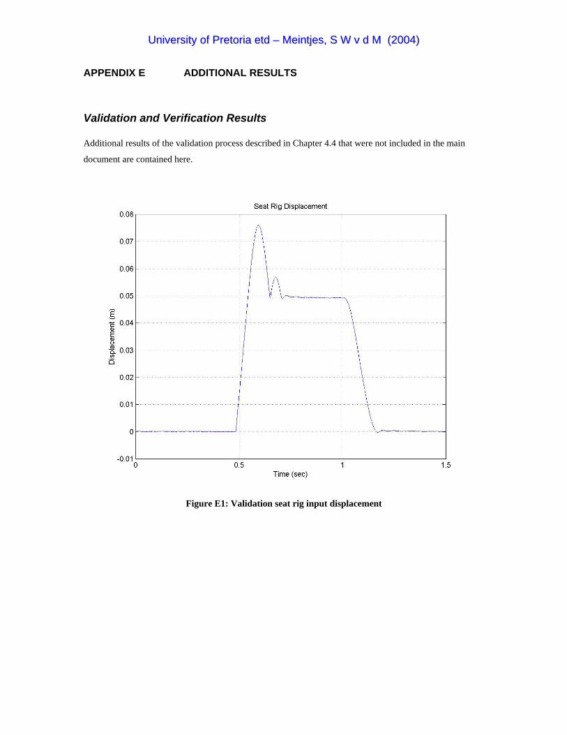
UUnniivveerrssiittyy ooff PPrreettoorriiaa eettdd –– MMeeiinnttjjeess,, SS WW vv dd MM ((22000044))
APPENDIX E ADDITIONAL RESULTS
Validation and Verification Results Additional results of the validation process described in Chapter 4.4 that were not included in the main
document are contained here.
Figure E1: Validation seat rig input displacement

UUnniivveerrssiittyy ooff PPrreettoorriiaa eettdd –– MMeeiinnttjjeess,, SS WW vv dd MM ((22000044))
Sled Impact Test Results Additional results of the sled impact tests described in Chapter 4.5
Figure E2: Test 1 prone concepts lumbar load comparison
Figure E3: Test 1 prone concepts head acceleration comparison

UUnniivveerrssiittyy ooff PPrreettoorriiaa eettdd –– MMeeiinnttjjeess,, SS WW vv dd MM ((22000044))
Figure E4: Test 2 prone concepts lumbar load comparison
Figure E5: Test 2 prone concepts head acceleration comparison

UUnniivveerrssiittyy ooff PPrreettoorriiaa eettdd –– MMeeiinnttjjeess,, SS WW vv dd MM ((22000044))
Figure E6: Test 1 neck axial loads and bending moments

UUnniivveerrssiittyy ooff PPrreettoorriiaa eettdd –– MMeeiinnttjjeess,, SS WW vv dd MM ((22000044))
Figure E7: Test 2 neck axial loads and bending moments

UUnniivveerrssiittyy ooff PPrreettoorriiaa eettdd –– MMeeiinnttjjeess,, SS WW vv dd MM ((22000044))
Fuselage Crash Test Results
Figure E8: Crash 1 neck axial loads and bending moments
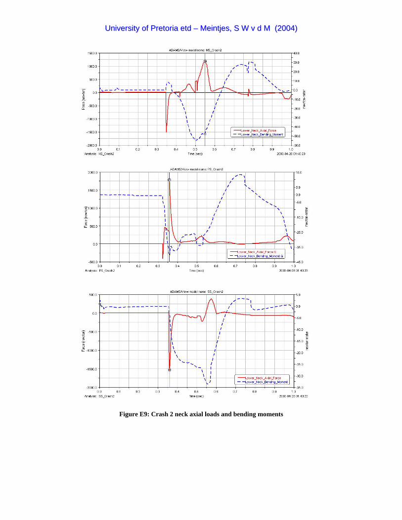
UUnniivveerrssiittyy ooff PPrreettoorriiaa eettdd –– MMeeiinnttjjeess,, SS WW vv dd MM ((22000044))
Figure E9: Crash 2 neck axial loads and bending moments

UUnniivveerrssiittyy ooff PPrreettoorriiaa eettdd –– MMeeiinnttjjeess,, SS WW vv dd MM ((22000044))
Figure E10: Crash 3 neck axial loads and bending moments

UUnniivveerrssiittyy ooff PPrreettoorriiaa eettdd –– MMeeiinnttjjeess,, SS WW vv dd MM ((22000044))
Values for Nij were calculated as follow:
As an example, from Figure E6 for the normal seated position the worst case combination for neck force FZ
and neck bending moment MY are indicated by the rings on the black vertical line at approximately 0.16
seconds. The values at this point in time are:
FZ = +1594N
MY = -65.94Nm
FINT = 4500N from Table 2.2 for a tension force
MINT = 125Nm from Table 2.2 for extension (negative) moment
Nij = FZ/FINT + MY/MINT
= 1594/4500 + 65.94/125
= 0.354 + 0.528
= 0.882
Table E1: Calculation of neck injury criteria
Analysis Position time (s) Fz (N) My (Nm) Fint Mint Nij Sled Test 1 Normal 0.159 1594 65.94 4500 125 0.882
Prone 0.059 3045 37.8 4500 125 0.979 Supine 0.286 1912 6.52 4500 310 0.446
Sled Test 2 Normal 0.095 10282 215.76 4500 125 4.011 Prone 0.07 3621 76.4 4500 125 1.416 Supine 0.094 10378 181.1 4500 125 3.755
Scenario 1 Normal 0.531 926 58.39 4500 125 0.673 Prone 0.405 2324 36.5 4500 125 0.808 Supine 0.425 1207 13.55 4500 125 0.377
Scenario 2 Normal 0.546 1182 48.62 4500 125 0.652 Prone 0.357 1784 38.97 4500 125 0.708 Supine 0.36 1553 4.15 4500 125 0.378
Scenario 3 Normal 0.475 1758 68.71 4500 125 0.940 Prone 0.372 2351 52.58 4500 125 0.943 Supine 0.73 749 36.55 4500 125 0.459
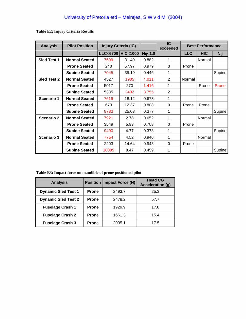
UUnniivveerrssiittyy ooff PPrreettoorriiaa eettdd –– MMeeiinnttjjeess,, SS WW vv dd MM ((22000044))
Table E2: Injury Criteria Results
Analysis Pilot Position Injury Criteria (IC) IC exceeded Best Performance
LLC<6700 HIC<1000 Nij<1.0 LLC HIC Nij Sled Test 1 Normal Seated 7599 31.49 0.882 1 Normal
Prone Seated 240 57.97 0.979 0 Prone Supine Seated 7045 39.19 0.446 1 Supine
Sled Test 2 Normal Seated 4527 1905 4.011 2 Normal Prone Seated 5017 270 1.416 1 Prone Prone Supine Seated 5335 2432 3.755 2
Scenario 1 Normal Seated 7619 18.12 0.673 1 Prone Seated 673 12.37 0.808 0 Prone Prone Supine Seated 8783 25.03 0.377 1 Supine
Scenario 2 Normal Seated 7921 2.78 0.652 1 Normal Prone Seated 3549 5.93 0.708 0 Prone Supine Seated 9490 4.77 0.378 1 Supine
Scenario 3 Normal Seated 7754 4.52 0.940 1 Normal Prone Seated 2203 14.64 0.943 0 Prone Supine Seated 10305 8.47 0.459 1 Supine
Table E3: Impact force on mandible of prone positioned pilot
Analysis Position Impact Force (N) Head CG Acceleration (g)
Dynamic Sled Test 1 Prone 2493.7 25.3
Dynamic Sled Test 2 Prone 2478.2 57.7
Fuselage Crash 1 Prone 1929.9 17.8
Fuselage Crash 2 Prone 1661.3 15.4
Fuselage Crash 3 Prone 2035.1 17.5
UUnniivveerrssiittyy ooff PPrreettoorriiaa eettdd –– MMeeiinnttjjeess,, SS WW vv dd MM ((22000044))
APPENDIX F COMPACT DISC
For future reference and as back-up purpose, this document together with other relevant data used to
complete the study was saved on a compact disc (cd) which is included at the end of this document. This
appendix will serve as a layout of the cd and will describe some of the content. The main thesis word
document and the following folders can be found on the cd:
• Pictures
• Result Files
• Videos
Pictures
This folder contains all the jpeg images used in the main document. The files are named according to the
numbering system of the main document as indicated the list of figures and list of tables.
Result Files
The analysis results obtained from ADAMS were saved in text format.
Videos
To visualize the animations without the ADAMS post-processing program, video clips of all the simulation
animations were created. This folder contains all the video clips, which can be viewed with a standard
Windows Media Player.