occupant crash protection
TRANSCRIPT
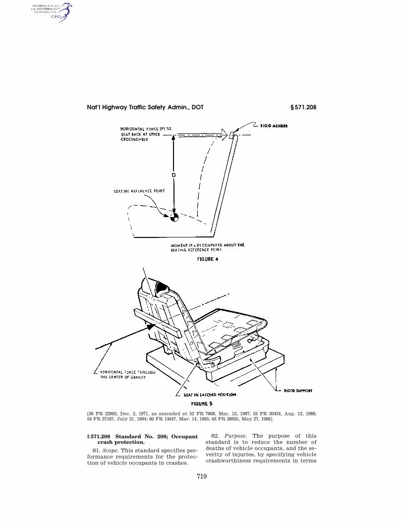
719
Nat’l Highway Traffic Safety Admin., DOT § 571.208
[36 FR 22902, Dec. 2, 1971, as amended at 52 FR 7868, Mar. 13, 1987; 53 FR 30434, Aug. 12, 1988; 59 FR 37167, July 21, 1994; 60 FR 13647, Mar. 14, 1995; 63 FR 28935, May 27, 1998]
§ 571.208 Standard No. 208; Occupant crash protection.
S1. Scope. This standard specifies per-formance requirements for the protec-tion of vehicle occupants in crashes.
S2. Purpose. The purpose of this standard is to reduce the number of deaths of vehicle occupants, and the se-verity of injuries, by specifying vehicle crashworthiness requirements in terms
VerDate Aug<31>2005 14:58 Dec 10, 2008 Jkt 214214 PO 00000 Frm 00729 Fmt 8010 Sfmt 8010 Y:\SGML\214214.XXX 214214 EC
01A
U91
.080
</G
PH
>E
C01
AU
91.0
81<
/GP
H>
yshi
vers
on
PR
OD
1PC
62 w
ith C
FR

720
49 CFR Ch. V (10–1–08 Edition) § 571.208
of forces and accelerations measured on anthropomorphic dummies in test crashes, and by specifying equipment requirements for active and passive re-straint systems.
S3. Application. (a) This standard ap-plies to passenger cars, multipurpose passenger vehicles, trucks, and buses. In addition, S9, Pressure vessels and ex-plosive devices, applies to vessels de-signed to contain a pressurized fluid or gas, and to explosive devices, for use in the above types of motor vehicles as part of a system designed to provide protection to occupants in the event of a crash.
(b) Notwithstanding any language to the contrary, any vehicle manufac-tured after March 19, 1997, and before September 1, 2006, that is subject to a dynamic crash test requirement con-ducted with unbelted dummies may meet the requirements specified in S5.1.2(a)(1), S5.1.2(a)(2), or S13 instead of the applicable unbelted requirement, unless the vehicle is certified to meet the requirements specified in S14.5, S15, S17, S19, S21, S23, and S25.
(c) For vehicles which are certified to meet the requirements specified in S13 instead of the otherwise applicable dy-namic crash test requirement con-ducted with unbelted dummies, compli-ance with S13 shall, for purposes of Standards No. 201, 203 and 209, be deemed as compliance with the unbelted frontal barrier requirements of S5.1.2.
S4. General requirements. S4.1 Passenger cars. S4.1.1 Passenger cars manufactured
from January 1, 1972, to August 31, 1973. Each passenger car manufactured from January 1, 1972, to August 31, 1973, in-clusive, shall meet the requirements of S4.1.1.1, S4.1.1.2, or S4.1.1.3. A protec-tion system that meets the require-ments of S4.1.1.1, or S4.1.1.2 may be in-stalled at one or more designated seat-ing positions of a vehicle that other-wise meets the requirements of S4.1.1.3.
S4.1.1.1 First option—complete passive protection system. The vehicle shall meet the crash protection require-ments of S5. by means that require no action by vehicle occupants.
S4.1.1.2 Second option—lap belt pro-tection system with belt warning. The ve-hicle shall—
(a) At each designated seating posi-tion have a Type 1 seatbelt assembly or a Type 2 seatbelt assembly with a de-tachable upper torso portion that con-forms to S7.1 and S7.2 of this standard;
(b) At each front outboard designated seating position, have a seat belt warn-ing system that conforms to S7.3; and
(c) Meet the frontal crash protection requirements of S5.1, in a perpen-dicular impact, with respect to anthropomorphic test devices in each front outboard designated seating posi-tion restrained only by Type 1 seat belt assemblies.
S4.1.1.3 Third option—lap and shoul-der belt protection system with belt warn-ing.
S4.1.1.3.1 Except for convertibles and open-body vehicles, the vehicle shall—
(a) At each front outboard designated seating position have a Type 2 seatbelt assembly that conforms to § 571.209 and S7.1 and S7.2 of this standard, with ei-ther an integral or detachable upper torso portion, and a seatbelt warning system that conforms to S7.3;
(b) At each designated seating posi-tion other than the front outboard po-sitions, have a Type 1 or Type 2 seat belt assembly that conforms to § 571.209 and to S7.1 and S7.2 of this standard; and
(c) When it perpendicularly impacts a fixed collision barrier, while moving longitudinally forward at any speed up to and including 30 m.p.h., under the test conditions of S8.1 with anthropomorphic test devices at each front outboard position restrained by Type 2 seatbelt assemblies, experience no complete separation of any load- bearing element of a seatbelt assembly or anchorage.
S4.1.1.3.2 Convertibles and open- body type vehicles shall at each des-ignated seating position have a Type 1 or Type 2 seatbelt assembly that con-forms to § 571.209 and to S7.1 and S7.2 of this standard, and at each front out-board designated seating position have a seatbelt warning system that con-forms to S7.3.
S4.1.2 Passenger cars manufactured on or after September 1, 1973, and before Sep-tember 1, 1986. Each passenger car man-ufactured on or after September 1, 1973, and before September 1, 1986, shall
VerDate Aug<31>2005 14:58 Dec 10, 2008 Jkt 214214 PO 00000 Frm 00730 Fmt 8010 Sfmt 8010 Y:\SGML\214214.XXX 214214yshi
vers
on
PR
OD
1PC
62 w
ith C
FR

721
Nat’l Highway Traffic Safety Admin., DOT § 571.208
meet the requirements of S4.1.2.1, S4.1.2.2 or S4.1.2.3. A protection system that meets the requirements of S4.1.2.1 or S4.1.2.2 may be installed at one or more designated seating positions of a vehicle that otherwise meets the re-quirements of S4.1.2.3.
S4.1.2.1 First option—frontal/angular automatic protection system. The vehicle shall:
(a) At each front outboard designated seating position meet the frontal crash protection requirements of S5.1 by means that require no action by vehi-cle occupants;
(b) At the front center designated seating position and at each rear des-ignated seating position have a Type 1 or Type 2 seat belt assembly that con-forms to Standard No. 209 and to S7.1 and S7.2; and
(c) Either. (1) Meet the lateral crash protection requirements of S5.2 and the rollover crash protection requirements of S5.3 by means that require no action by vehicle occupants; or
(2) At each front outboard designated seating position have a Type 1 or Type 2 seat belt assembly that conforms to Standard No. 209 and S7.1 through S7.3, and that meets the requirements of S5.1 with front test dummies as re-quired by S5.1, restrained by the Type 1 or Type 2 seat belt assembly (or the pelvic portion of any Type 2 seat belt assembly which has a detachable upper torso belt) in addition to the means that require no action by the vehicle occupant.
S4.1.2.2 Second option—head-on auto-matic protection system. The vehicle shall—
(a) At each designated seating posi-tion have a Type 1 seat belt assembly or Type 2 seat belt assembly with a de-tachable upper torso portion that con-forms to S7.1 and S7.2 of this standard.
(b) At each front outboard designated seating position, meet the frontal crash protection requirements of S5.1, in a perpendicular impact, by means that require no action by vehicle occu-pants;
(c) At each front outboard designated seating position, meet the frontal crash protection requirements of S5.1, in a perpendicular impact, with a test device restrained by a Type 1 seat belt assembly; and
(d) At each front outboard designated seating position, have a seat belt warn-ing system that conforms to S7.3.
S4.1.2.3 Third option—lap and shoul-der belt protection system with belt warn-ing.
S4.1.2.3.1 Except for convertibles and open-body vehicles, the vehicle shall—
(a) At each front outboard designated seating position have a seat belt as-sembly that conforms to S7.1 and S7.2 of this standard, and a seat belt warn-ing system that conforms to S7.3. The belt assembly shall be either a Type 2 seat belt assembly with a nondetach-able shoulder belt that conforms to Standard No. 209 (§ 571.209), or a Type 1 seat belt assembly such that with a test device restrained by the assembly the vehicle meets the frontal crash pro-tection requirements of S5.1 in a per-pendicular impact.
(b) At any center front designated seating position, have a Type 1 or Type 2 seat belt assembly that conforms to Standard No. 209 (§ 571.209) and to S7.1 and S7.2 of this standard, and a seat belt warning system that conforms to S7.3; and
(c) At each other designated seating position, have a Type 1 or Type 2 seat belt assembly that conforms to Stand-ard No. 209 (§ 571.209) and S7.1 and S7.2 of this standard.
S4.1.2.3.2 Convertibles and open- body type vehicles shall at each des-ignated seating position have a Type 1 or Type 2 seat belt assembly that con-forms to Standard No. 209 (§ 571.209) and to S7.1 and S7.2 of this standard, and at each front designated seating position have a seat belt warning system that conforms to S7.3.
S4.1.3 Passenger cars manufactured on or after September 1, 1986, and before Sep-tember 1, 1989.
S4.1.3.1 Passenger cars manufactured on or after September 1, 1986, and before September 1, 1987.
S4.1.3.1.1 Subject to S4.1.3.1.2 and S4.1.3.4, each passenger car manufac-tured on or after September 1, 1986, and before September 1, 1987, shall comply with the requirements of S4.1.2.1, S4.1.2.2 or S4.1.2.3. A vehicle shall not be deemed to be in noncompliance with this standard if its manufacturer estab-lishes that it did not have reason to
VerDate Aug<31>2005 14:58 Dec 10, 2008 Jkt 214214 PO 00000 Frm 00731 Fmt 8010 Sfmt 8010 Y:\SGML\214214.XXX 214214yshi
vers
on
PR
OD
1PC
62 w
ith C
FR

722
49 CFR Ch. V (10–1–08 Edition) § 571.208
know in the exercise of due care that such vehicle is not in conformity with the requirement of this standard.
S4.1.3.1.2 Subject to S4.1.3.4 and S4.1.5, the amount of passenger cars, specified in S4.1.3.1.1 complying with the requirements of S4.1.2.1 shall be not less than 10 percent of:
(a) The average annual production of passenger cars manufactured on or after September 1, 1983, and before Sep-tember 1, 1986, by each manufacturer, or
(b) The manufacturer’s annual pro-duction of passenger cars during the period specified in S4.1.3.1.1.
S4.1.3.1.3 A manufacturer may ex-clude convertibles which do not comply with the requirements of S4.1.2.1, when it is calculating its average annual pro-duction under S4.1.3.1.2(a) or its annual production under S4.1.3.1.2(b).
S4.1.3.2 Passenger cars manufactured on or after September 1, 1987, and before September 1, 1988.
S4.1.3.2.1 Subject to S4.1.3.2.2 and S4.1.3.4, each passenger car manufac-tured on or after September 1, 1987, and before September 1, 1988, shall comply with the requirements of S4.1.2.1, S4.1.2.2 or S4.1.2.3. A vehicle shall not be deemed to be in noncompliance with this standard if its manufacturer estab-lishes that it did not have reason to know in the exercise of due care that such vehicle is not in conformity with the requirement of this standard.
S4.1.3.2.2 Subject to S4.1.3.4 and S4.1.5, the amount of passenger cars specified in S4.1.3.2.1 complying with the requirements of S4.1.2.1. shall be not less than 25 percent of:
(a) The average annual production of passenger cars manufactured on or after September 1, 1984, and before Sep-tember 1, 1987, by each manufacturer, or
(b) The manufacturer’s annual pro-duction of passenger cars during the period specified in S4.1.3.2.1.
S4.1.3.2.3 A manufacturer may ex-clude convertibles which do not comply with the requirements of S4.1.2.1, when it is calculating its average annual pro-duction under S4.1.3.2.2(a) or its annual production under S4.1.3.2.2(b).
S4.1.3.3 Passenger cars manufactured on or after September 1, 1988, and before September 1, 1989.
S4.1.3.3.1 Subject to S4.1.3.3.2 and S4.1.3.4, each passenger car manufac-tured on or after September 1, 1988, and before September 1, 1989, shall comply with the requirements of S4.1.2.1, S4.1.2.2 or S4.1.2.3. A vehicle shall not be deemed to be in noncompliance with this standard if its manufacturer estab-lishes that it did not have reason to know in the exercise of due care that such vehicle is not in conformity with the requirement of this standard.
S4.1.3.3.2 Subject to S4.1.3.4 and S4.1.5, the amount of passenger cars specified in S4.1.3.3.1 complying with the requirements of S4.1.2.1 shall be not less than 40 percent of:
(a) The average annual production of passenger cars manufactured on or after September 1, 1985, and before Sep-tember 1, 1988, by each manufacturer or
(b) The manufacturer’s annual pro-duction of passenger cars during the period specified in S4.1.3.3.1.
S4.1.3.3.3 A manufacturer may ex-clude convertibles which do not comply with the requirements of S4.1.2.1, when it is calculating its average annual pro-duction under S4.1.3.3.2(a) or its annual production under S4.1.3.3.2(b).
S4.1.3.4 Calculation of complying pas-senger cars. (a) For the purposes of cal-culating the numbers of cars manufac-tured under S4.1.3.1.2, S4.1.3.2.2, or S4.1.3.3.2 to comply with S4.1.2.1:
(1) Each car whose driver’s seating position complies with the require-ments of S4.1.2.1(a) by means not in-cluding any type of seat belt and whose front right seating position will com-ply with the requirements of S4.1.2.1(a) by any means is counted as 1.5 vehi-cles, and
(2) Each car whose driver’s seating position complies with the require-ments of S4.1.2.1(a) by means not in-cluding any type of seat belt and whose right front seat seating position is equipped with a manual Type 2 seat belt is counted as one vehicle.
(b) For the purposes of complying with S4.1.3.1.2, a passenger car may be counted if it:
(1) Is manufactured on or after Sep-tember 1, 1985, but before September 1, 1986, and
(2) Complies with S4.1.2.1.
VerDate Aug<31>2005 14:58 Dec 10, 2008 Jkt 214214 PO 00000 Frm 00732 Fmt 8010 Sfmt 8010 Y:\SGML\214214.XXX 214214yshi
vers
on
PR
OD
1PC
62 w
ith C
FR

723
Nat’l Highway Traffic Safety Admin., DOT § 571.208
(c) For the purposes of complying with S4.1.3.2.2, a passenger car may be counted if it:
(1) Is manufactured on or after Sep-tember 1, 1985, but before September 1, 1987,
(2) Complies with S4.1.2.1, and (3) Is not counted toward compliance
with S4.1.3.1.2 (d) For the purposes of complying
with S4.1.3.3.2, a passenger car may be counted if it:
(1) Is manufactured on or after Sep-tember 1, 1985, but before September 1, 1988,
(2) Complies with S4.1.2.1, and (3) Is not counted toward compliance
with S4.1.3.1.2 or S4.1.3.2.2. S4.1.3.5 Passenger cars produced by
more than one manufacturer. S4.1.3.5.1 For the purposes of calcu-
lating average annual production of passenger cars for each manufacturer and the amount of passenger cars man-ufactured by each manufacturer under S4.1.3.1.2, S4.1.3.2.2 or S4.1.3.3.2, a pas-senger car produced by more than one manufacturer shall be attributed to a single manufacturer as follows, subject to S4.1.3.5.2:
(a) A passenger car which is imported shall be attributed to the importer.
(b) A passenger car manufactured in the United States by more than one manufacturer, one of which also mar-kets the vehicle, shall be attributed to the manufacturer which markets the vehicle.
S4.1.3.5.2 A passenger car produced by more than one manufacturer shall be attributed to any one of the vehi-cle’s manufacturers specified by an ex-press written contract, reported to the National Highway Traffic Safety Ad-ministration under 49 CFR part 585, be-tween the manufacturer so specified and the manufacturer to which the ve-hicle would otherwise be attributed under S4.1.3.5.1.
S4.1.4 Passenger cars manufactured on or after September 1, 1989, but be-fore September 1, 1996.
S4.1.4.1 Except as provided in S4.1.4.2, each passenger car manufac-tured on or after September 1, 1989 shall comply with the requirements of S4.1.2.1. Any passenger car manufac-tured on or after September 1, 1989 and before September 1, 1993 whose driver’s
designated seating position complies with the requirements of S4.1.2.1(a) by means not including any type of seat belt and whose right front designated seating position is equipped with a manual Type 2 seat belt so that the seating position complies with the oc-cupant crash protection requirements of S5.1, with the Type 2 seat belt as-sembly adjusted in accordance with S7.4.2, shall be counted as a vehicle complying with S4.1.2.1. A vehicle shall not be deemed to be in noncompliance with this standard if its manufacturer establishes that it did not know in the exercise of due care that such vehicle is not in conformity with this standard.
S4.1.4.2 (a) Each passenger car, other than a convertible, manufactured before December 11, 1989 may be equipped with, and each passenger car, other than a convertible, manufactured on or after December 11, 1989 and before September 1, 1990 shall be equipped with a Type 2 seat belt assembly at every forward-facing rear outboard des-ignated seating position. Type 2 seat belt assemblies installed pursuant to this provision shall comply with Stand-ard No. 209 (49 CFR 571.209) and with S7.1.1 of this standard.
(b) Except as provided in S4.1.4.2.1 and S4.1.4.2.2, each passenger car, other than a convertible, manufactured on or after September 1, 1990 and each con-vertible passenger car manufactured on or after September 1, 1991 shall be equipped with an integral Type 2 seat belt assembly at every forward-facing rear outboard designated seating posi-tion. Type 2 seat belt assemblies in-stalled in compliance with this require-ment shall comply with Standard No. 209 (49 CFR 571.209) and with S7.1 an S7.2 of this standard. If a Type 2 seat belt assembly installed in compliance with this requirement incorporates any webbing tension-relieving device, the vehicle owner’s manual shall include the information specified in S7.4.2(b) of this standard for the tension relieving device, and the vehicle shall comply with S7.4.2(c) of this standard.
(c) As used in this section, ‘‘rear out-board designated seating position’’ means any ‘‘outboard designated seat-ing position’’ (as that term is defined at 49 CFR 571.3) that is rearward of the front seat(s), except any designated
VerDate Aug<31>2005 14:58 Dec 10, 2008 Jkt 214214 PO 00000 Frm 00733 Fmt 8010 Sfmt 8010 Y:\SGML\214214.XXX 214214yshi
vers
on
PR
OD
1PC
62 w
ith C
FR

724
49 CFR Ch. V (10–1–08 Edition) § 571.208
seating position adjacent to a walkway that is located between the seat and the near side of the vehicle and is de-signed to allow access to more rear-ward seating positions.
S4.1.4.2.1 Any rear outboard des-ignated seating position with a seat that can be adjusted to be forward-fac-ing and to face some other direction shall either:
(i) Meet the requirements of S4.1.4.2 with the seat in any position in which it can be occupied while the vehicle is in motion; or
(ii) When the seat is in its forward- facing position, have a Type 2 seat belt assembly with an upper torso restraint that conforms to S7.1 and S7.2 of this standard and that adjusts by means of an emergency locking retractor that conforms with Standard No. 209 (49 CFR 571.209), which upper torso re-straint may be detachable at the buck-le, and, when the seat is in any posi-tion in which it can be occupied while the vehicle is in motion, have a Type 1 seat belt or the pelvic portion of a Type 2 seat belt assembly that con-forms to S7.1 and S7.2 of this standard.
S4.1.4.2.2 Any rear outboard des-ignated seating position on a readily removable seat (that is, a seat designed to be easily removed and replaced by means installed by the manufacturer for that purpose) in a vehicle manufac-tured on or after September 1, 1992 shall meet the requirements of S4.1.4.2 and may use an upper torso belt that detaches at either its upper or lower anchorage points, but not both anchor-age points, to meet those require-ments. The means for detaching the upper torso belt may use a pushbutton action.
S4.1.5 Passenger cars manufactured on or after September 1, 1996.
S4.1.5.1 Frontal/angular automatic protection system. (a) Each passenger car manufactured on or after Sep-tember 1, 1996 shall:
(1) At each front outboard designated seating position meet the frontal crash protection requirements of S5.1 by means that require no action by vehi-cle occupants;
(2) At any front designated seating positions that are not ‘‘outboard des-ignated seating positions,’’ as that term is defined at 49 CFR 571.3, and at
any rear designated seating positions that are not ‘‘rear outboard designated seating positions,’’ as that term is de-fined at S4.1.4.2(c) of this standard, have a Type 1 or Type 2 seat belt as-sembly that conforms to Standard No. 209 and S7.1 and S7.2 of this standard; and
(3) At each front designated seating position that is an ‘‘outboard des-ignated seating position,’’ as that term is defined at 49 CFR 571.3, and at each forward-facing rear designated seating position that is a ‘‘rear outboard des-ignated seating positions,’’ as that term is defined at S4.1.4.2(c) of this standard, have a Type 2 seat belt as-sembly that conforms to Standard No. 209 and S7.1 through S7.3 of this stand-ard, and, in the case of the Type 2 seat belt assemblies installed at the front outboard designated seating positions, meet the frontal crash protection re-quirements with the appropriate anthropomorphic test dummy re-strained by the Type 2 seat belt assem-bly in addition to the means that re-quires no action by the vehicle occu-pant.
(b) For the purposes of sections S4.1.5 through S4.1.5.3 and S4.2.6 through S4.2.6.2 of this standard, an inflatable restraint system means an air bag that is activated in a crash.
S4.1.5.2 Passenger cars manufactured on or after September 1, 1996 and before September 1, 1997.
S4.1.5.2.1 The amount of passenger cars complying with the requirement of S4.1.5.1(a)(1) by means of an inflat-able restraint system at the driver’s and right front passenger’s position shall be not less than 95 percent of the manufacturer’s total production of pas-senger cars manufactured on or after September 1, 1996, and before Sep-tember 1, 1997. A vehicle shall not be deemed to be in noncompliance with this standard if its manufacturer estab-lishes that it did not have reason to know in the exercise of due care that such vehicle is not in conformity with the requirement of this standard.
S4.1.5.2.2 Passenger cars produced by more than one manufacturer.
S4.1.5.2.2.1 For the purpose of calcu-lating the production of passenger cars by each manufacturer during the pe-riod specified in S4.1.5.2, a passenger
VerDate Aug<31>2005 14:58 Dec 10, 2008 Jkt 214214 PO 00000 Frm 00734 Fmt 8010 Sfmt 8010 Y:\SGML\214214.XXX 214214yshi
vers
on
PR
OD
1PC
62 w
ith C
FR

725
Nat’l Highway Traffic Safety Admin., DOT § 571.208
car produced by more than one manu-facturer shall be attributed to a single manufacturer as follows, subject to S4.1.5.2.2.2:
(a) A passenger car that is imported into the United States shall be attrib-uted to the importer.
(b) A passenger car manufactured within the United States by more than one manufacturer, one of which also markets the vehicle, shall be attrib-uted to the manufacturer that markets the vehicle.
S4.1.5.2.2.2 A passenger car produced by more than one manufacturer shall be attributed to any one of the vehi-cle’s manufacturers, as specified in an express written contract, reported to the National Highway Traffic Safety Administration pursuant to part 585 of this chapter, between the manufac-turer so specified and the manufacturer to which the vehicle otherwise would be attributed, pursuant to S4.1.5.2.2.1.
S4.1.5.3 Passenger cars manufactured on or after September 1, 1997. Each pas-senger car manufactured on or after September 1, 1997 shall comply with the requirement of S4.1.5.1(a)(1) by means of an inflatable restraint system at the driver’s and right front pas-senger’s position. A vehicle shall not be deemed to be in noncompliance with this standard if its manufacturer estab-lishes that it did not have reason to know in the exercise of due care that such vehicle is not in conformity with the requirement of this standard.
S4.1.5.4 Passenger cars certified to S14. Each passenger car certified to S14 shall, at each front outboard des-ignated seating position, meet the ap-plicable frontal crash protection re-quirements of S5.1.2(b) by means of an inflatable restraint system that re-quires no action by vehicle occupants.
S4.1.5.5 Passenger cars manufactured on or after September 1, 2007.
S4.1.5.5.1 Except as provided in S4.1.5.5.2, each passenger car shall have a Type 2 seat belt assembly that con-forms to Standard No. 209 and to S7.1 and S7.2 of this standard at each rear designated seating position, except that side-facing designated seating po-sitions shall have a Type 1 or Type 2 seat belt assembly that conforms to Standard No. 209 and to S7.1 and S7.2 of this standard.
S4.1.5.5.2 Any inboard designated seating position on a seat for which the entire seat back can be folded (includ-ing the head restraints and any other part of the vehicle attached to the seat back) such that no part of the seat back extends above a horizontal plane located 250 mm above the highest SRP located on the seat may meet the re-quirements of S4.1.5.5.1 by use of a belt incorporating a release mechanism that detaches both the lap and shoul-der portion at either the upper or lower anchorage point, but not both. The means of detachment shall be a key or key-like object.
S4.2 Trucks and multipurpose pas-senger vehicles with a GVWR of 10,000 pounds or less. As used in this section, vehicles manufactured for operation by persons with disabilities means vehicles that incorporate a level change device (e.g., a wheelchair lift or a ramp) for onloading or offloading an occupant in a wheelchair, an interior element of de-sign intended to provide the vertical clearance necessary to permit a person in a wheelchair to move between the lift or ramp and the driver’s position or to occupy that position, and either an adaptive control or special driver seat-ing accommodation to enable persons who have limited use of their arms or legs to operate a vehicle. For purposes of this definition, special driver seating accommodations include a driver’s seat easily removable with means installed for that purpose or with simple tools, or a driver’s seat with extended adjust-ment capability to allow a person to easily transfer from a wheelchair to the driver’s seat.
S4.2.1 Trucks and multipurpose pas-senger vehicles with a GVWR of 10,000 pounds or less, manufactured on or after January 1, 1976 and before September 1, 1991. Each truck and multipurpose pas-senger vehicle, with a gross vehicle weight rating of 10,000 pounds or less, manufactured before September 1, 1991, shall meet the requirements of S4.1.2.1, or at the option of the manufacturer, S4.1.2.2 or S4.1.2.3 (as specified for pas-senger cars), except that forward con-trol vehicles manufactured prior to September 1, 1981, convertibles, open- body type vehicles, walk-in van-type trucks, motor homes, vehicles designed
VerDate Aug<31>2005 14:58 Dec 10, 2008 Jkt 214214 PO 00000 Frm 00735 Fmt 8010 Sfmt 8010 Y:\SGML\214214.XXX 214214yshi
vers
on
PR
OD
1PC
62 w
ith C
FR

726
49 CFR Ch. V (10–1–08 Edition) § 571.208
to be exclusively sold to the U.S. Post-al Service, and vehicles carrying chas-sis-mount campers may instead meet the requirements of S4.2.1.1 or S4.2.1.2.
S4.2.1.1 First option—complete auto-matic protection system. The vehicle shall meet the crash protection re-quirements of S5 by means that require no action by vehicle occupants.
S4.2.1.2 Second option—belt system. The vehicle shall have seat belt assem-blies that conform to Standard 209 (49 CFR 571.209) installed as follows:
(a) A Type 1 or Type 2 seat belt as-sembly shall be installed for each des-ignated seating position in convertibles, open-body type vehicles, and walk-in van-type trucks.
(b) In vehicles manufactured for op-eration by persons with disabilities, a Type 2 or Type 2A seat belt assembly shall be installed for the driver’s seat-ing position, a Type 2 seat belt assem-bly shall be installed for each other outboard designated seating position that includes the windshield header within the head impact area, and a Type 1 or Type 2 seat belt assembly shall be installed for each other des-ignated seating position.
(c) In all vehicles except those for which requirements are specified in S4.2.1.2 (a) or (b), a Type 2 seat belt as-sembly shall be installed for each out-board designated seating position that includes the windshield header within the head impact area, and a Type 1 or Type 2 seat belt assembly shall be in-stalled for each other designated seat-ing position.
S4.2.2 Trucks and multipurpose pas-senger vehicles with a GVWR of 8,500 pounds or less and an unloaded vehicle weight of 5,500 pounds or less, manufac-tured on or after September 1, 1991 and before September 1, 1997. Except as pro-vided in S4.2.4, each truck and multi-purpose passenger vehicle, with a gross vehicle weight rating of 8,500 pounds or less and an unloaded vehicle weight of 5,500 pounds or less, manufactured on or after September 1, 1991 and before September 1, 1997, shall meet the re-quirements of S4.1.2.1, or at the option of the manufacturer, S4.1.2.2 or S4.1.2.3 (as specified for passenger cars), except that convertibles, open-body type vehi-cles, walk-in van-type trucks, motor homes, vehicles designed to be exclu-
sively sold to the U.S. Postal Service, vehicles carrying chassis-mount camp-ers, and vehicles manufactured for op-eration by persons with disabilities may instead meet the requirements of S4.2.1.1 or S4.2.1.2. Each Type 2 seat belt assembly installed in a front out-board designated seating position in accordance with S4.1.2.3 shall meet the requirements of S4.6.
S4.2.3 Trucks and multipurpose pas-senger vehicles manufactured on or after September 1, 1991 with either a GVWR or more than 8,500 pounds but not greater than 10,000 pounds or with an unloaded vehicle weight greater than 5,500 pounds and a GVWR of 10,000 pounds or less. Ex-cept as provided in S4.2.4, each truck and multipurpose passenger vehicle manufactured on or after September 1, 1991, that has either a gross vehicle weight rating which is greater than 8,500 pounds, but not greater than 10,000 pounds, or has an unloaded vehi-cle weight greater than 5,500 pounds and a GVWR of 10,000 pounds or less, shall meet the requirements of S4.1.2.1, or at the option of the manufacturer, S4.1.2.2 or S4.1.2.3 (as specified for pas-senger cars), except that convertibles, open-body type vehicles, walk-in van- type trucks, motor homes, vehicles de-signed to be exclusively sold to the U.S. Postal Service, and vehicles car-rying chassis-mount campers may in-stead meet the requirements of S4.2.1.1 or S4.2.1.2.
S4.2.4 Rear outboard seating positions in trucks and multipurpose passenger ve-hicles manufactured on or after September 1, 1991 with a GVWR of 10,000 pounds or less. Except as provided in S4.2.4.2 and S4.2.4.3, each truck and each multipur-pose passenger vehicle, other than a motor home, manufactured on or after September 1, 1991 that has a gross vehi-cle weight rating of 10,000 pounds or less shall be equipped with an integral Type 2 seat belt assembly at every for-ward-facing rear outboard designated seating position. Type 2 seat belt as-semblies installed in compliance with this requirement shall comply with Standard No. 209 (49 CFR 571.209) and with S7.1 and S7.2 of this standard. If a Type 2 seat belt assembly installed in compliance with this requirement in-corporates any webbing tension-reliev-ing device, the vehicle owner’s manual
VerDate Aug<31>2005 14:58 Dec 10, 2008 Jkt 214214 PO 00000 Frm 00736 Fmt 8010 Sfmt 8010 Y:\SGML\214214.XXX 214214yshi
vers
on
PR
OD
1PC
62 w
ith C
FR

727
Nat’l Highway Traffic Safety Admin., DOT § 571.208
shall include the information specified in S7.4.2(b) of this standard for the ten-sion relieving device, and the vehicle shall comply with S7.4.2(c) of this standard.
S4.2.4.1 As used in this section— (a) [Reserved] (b) Rear outboard designated seating
position means any ‘‘outboard des-ignated seating position’’ (as that term is defined at 49 CFR 571.3) that is rear-ward of the front seat(s), except any designated seating positions adjacent to a walkway located between the seat and the side of the vehicle, which walk-way is designed to allow access to more rearward seating positions.
S4.2.4.2 Any rear outboard des-ignated seating position with a seat that can be adjusted to be forward-fac-ing and to face some other direction shall either:
(i) Meet the requirements of S4.2.4 with the seat in any position in which it can be occupied while the vehicle is in motion; or
(ii) When the seat is in its forward- facing position, have a Type 2 seat belt assembly with an upper torso restraint that conforms to S7.1 and S7.2 of this standard and that adjusts by means of an emergency locking retractor that conforms with Standard No. 209 (49 CFR 571.209), which upper torso re-straint may be detachable at the buck-le, and, when the seat is in any posi-tion in which it can be occupied while the vehicle is in motion, have a Type 1 seat belt or the pelvic portion of a Type 2 seat belt assembly that con-forms to S7.1 and S7.2 of this standard.
S4.2.4.3 Any rear outboard designated seating position on a readily removable seat (that is, a seat designed to be eas-ily removed and replaced by means in-stalled by the manufacturer for that purpose) in a vehicle manufactured on or after September 1, 1992 shall meet the requirements of S4.2.4 and may use an upper torso belt that detaches at ei-ther its upper or lower anchorage point, but not both anchorage points, to meet those requirements. The means for detaching the upper torso belt may use a pushbutton action.
S4.2.5 Trucks, buses, and multipurpose passenger vehicles with a GVWR of 8,500 pounds or less and an unloaded vehicle weight of 5,500 pounds or less manufac-
tured on or after September 1, 1994, and before September 1, 1997.
S4.2.5.1 Trucks, buses, and multipur-pose passenger vehicles with a GVWR of 8,500 pounds or less and an unloaded ve-hicle weight of 5,500 pounds or less manu-factured on or after September 1, 1994, and before September 1, 1995.
S4.2.5.1.1 Subject to S4.2.5.1.2 and S4.2.5.5 and except as provided in S4.2.4, each truck, bus and multipurpose pas-senger vehicle, other than walk-in van- type trucks, vehicles designed to be ex-clusively sold to the U.S. Postal Serv-ice, and vehicles manufactured for op-eration by persons with disabilities, with a GVWR of 8,500 pounds or less and an unloaded vehicle weight of 5,500 pounds or less that is manufactured on or after September 1, 1994 and before September 1, 1995, shall comply with the requirements of S4.1.2.1, S4.1.2.2, or S4.1.2.3 (as specified for passenger cars). A vehicle shall not be deemed to be in noncompliance with this standard if its manufacturer establishes that it did not have reason to know in the ex-ercise of due care that such vehicle is not in conformity with the require-ment of standard.
S4.2.5.1.2 Subject to S4.2.5.5, the amount of trucks, buses, and multipur-pose passenger vehicles specified in S4.2.5.1.1 complying with S4.1.2.1 (as specified for passenger cars) shall be not less than 20 percent of:
(a) The average annual production of trucks, buses, and multipurpose pas-senger vehicles with a GVWR of 8,500 pounds or less and an unloaded vehicle weight of 5,500 pounds or less manufac-tured on or after September 1, 1991, and before September 1, 1994, by each man-ufacturer that produced such vehicles during each of those annual production periods, or
(b) The manufacturer’s total produc-tion of trucks, buses, and multipurpose passenger vehicle with a GVWR of 8,500 pounds or less and an unloaded vehicle weight of 5,500 pounds or less during the period specified in S4.2.5.1.1.
S4.2.5.2 Trucks, buses, and multipur-pose passenger vehicles with a GVWR of 8,500 pounds or less and an unloaded ve-hicle weight of 5,500 pounds or less manu-factured on or after September 1, 1995 and before September 1, 1996.
VerDate Aug<31>2005 14:58 Dec 10, 2008 Jkt 214214 PO 00000 Frm 00737 Fmt 8010 Sfmt 8010 Y:\SGML\214214.XXX 214214yshi
vers
on
PR
OD
1PC
62 w
ith C
FR

728
49 CFR Ch. V (10–1–08 Edition) § 571.208
S4.2.5.2.1 Subject to S4.2.5.2.2 and S4.2.5.5 and except as provided in S4.2.4, each truck, bus, and multipurpose pas-senger vehicle, other than walk-in van- type trucks, vehicles designed to be ex-clusively sold to the U.S. Postal Serv-ice, and vehicles manufactured for op-eration by persons with disabilities, with a GVWR of 8,500 pounds or less and an unloaded vehicle weight of 5,500 pounds or less that is manufactured on or after September 1, 1995 and before September 1, 1996, shall comply with the requirements of S4.1.2.1, S4.1.2.2, or S4.1.2.3 (as specified for passenger cars). A vehicle shall not be deemed to be in noncompliance with this standard if its manufacturer establishes that it did not have reason to know in the ex-ercise of due care that such vehicle is not in conformity with the require-ment of this standard.
S4.2.5.2.2 Subject to S4.2.5.5, the amount of trucks, buses, and multipur-pose passenger vehicles specified in S4.2.5.2.1 complying with S4.1.2.1 (as specified for passenger cars) shall be not less than 50 percent of:
(a) The average annual production of trucks, buses, and multipurpose pas-senger vehicles with a GVWR of 8,500 pounds or less and an unloaded vehicle weight of 5,500 pounds or less manufac-tured on or after September 1, 1992, and before September 1, 1995, by each man-ufacturer that produced such vehicles during each of those annual production periods, or
(b) The manufacturer’s total produc-tion of trucks, buses, and multipurpose passenger vehicles with a GVWR of 8,500 pounds or less and an unloaded ve-hicle weight of 5,500 pounds or less dur-ing the period specified in S4.2.5.2.1.
S4.2.5.3 Trucks, buses, and multipur-pose passenger vehicles with a GVWR of 8,500 pounds or less and an unloaded ve-hicle weight of 5,500 pounds or less manu-factured on or after September 1, 1996 and before September 1, 1997.
S4.2.5.3.1 Subject to S4.2.5.3.2 and S4.2.5.5 and except as provided in S4.2.4, each truck, bus, and multipurpose pas-senger vehicle, other than walk-in van- type trucks, vehicles designed to be ex-clusively sold to the U.S. Postal Serv-ice, and vehicles manufactured for op-eration by persons with disabilities, with a GVWR of 8,500 pounds or less
and an unloaded vehicle weight of 5,500 pounds or less that is manufactured on or after September 1, 1996 and before September 1, 1997, shall comply with the requirements of S4.1.2.1, S4.1.2.2, or S4.1.2.3 (as specified for passenger cars). A vehicle shall not be deemed to be in noncompliance with this standard if its manufacturer establishes that it did not have reason to know in the ex-ercise of due care that such vehicle is not in conformity with the require-ment of this standard.
S4.2.5.3.2 Subject to S4.2.5.5, the amount of trucks, buses, and multipur-pose passenger vehicles specified in S4.2.5.3.1 complying with S4.1.2.1 (as specified for passenger cars) shall be not less than 90 percent of:
(a) The average annual production of trucks, buses, and multipurpose pas-senger vehicles with a GVWR of 8,500 pounds or less and an unloaded vehicle weight of 5,500 pounds or less manufac-tured on or after September 1, 1993, and before September 1, 1996, by each man-ufacturer that produced such vehicles during each of those annual production periods, or
(b) The manufacturer’s total produc-tion of trucks, buses, and multipurpose passenger vehicles with a GVWR of 8,500 pounds or less and an unloaded ve-hicle weight of 5,500 pounds or less dur-ing the period specified in S4.2.5.3.1.
S4.2.5.4 Alternative phase-in schedule. A manufacturer may, at its option, comply with the requirements of this section instead of complying with the requirements set forth in S4.2.5.1, S4.2.5.2, and S4.2.5.3.
(a) Except as provided in S4.2.4, each truck, bus, and multipurpose passenger vehicle, other than walk-in van-type trucks, vehicles designed to be exclu-sively sold to the U.S. Postal Service, and vehicles manufactured for oper-ation by persons with disabilities, with a GVWR of 8,500 pounds or less and an unloaded vehicle weight of 5,500 pounds or less that is manufactured on or after September 1, 1994 and before September 1, 1995 shall comply with the require-ments of S4.1.2.1, S4.1.2.2, or S4.1.2.3 (as specified for passenger cars).
(b) Except as provided in S4.2.4, each truck, bus, and multipurpose passenger vehicle, other than walk-in van-tape
VerDate Aug<31>2005 14:58 Dec 10, 2008 Jkt 214214 PO 00000 Frm 00738 Fmt 8010 Sfmt 8010 Y:\SGML\214214.XXX 214214yshi
vers
on
PR
OD
1PC
62 w
ith C
FR

729
Nat’l Highway Traffic Safety Admin., DOT § 571.208
trucks, vehicles designed to be exclu-sively sold to the U.S. Postal Service, and vehicles manufactured for oper-ation by persons with disabilities, with a GVWR of 8,500 pounds or less and an unloaded vehicle weight of 5,500 pounds or less that is manufactured on or after September 1, 1995 shall comply with the requirements of S4.1.2.1 (as speci-fied for passenger cars) of this stand-ard. A vehicle shall not be deemed to be in noncompliance with this standard if its manufacturer establishes that it did not have reason to know in the ex-ercise of due care that such vehicle is not in conformity with the require-ment of this standard.
(c) Each truck, bus, and multipurpose passenger vehicle with a GVWR of 8,500 pounds or less and an unloaded vehicle weight of 5,500 pounds or less manufac-tured on or after September 1, 1995, but before September 1, 1998, whose driver’s seating position complies with the re-quirements of S4.1.2.1(a) of this stand-ard by means not including any type of seat belt and whose right front pas-senger’s seating position is equipped with a manual Type 2 seat belt that complies with S5.1 of this standard, with the seat belt assembly adjusted in accordance with S7.4.2, shall be count-ed as a vehicle complying with S4.1.2.1.
S4.2.5.5 Calculation of complying trucks, buses, and multipurpose passenger vehicles with a GVWR of 8,500 pounds or less and an unloaded vehicle weight of 5,500 pounds or less.
(a) For the purposes of the calcula-tions required in S4.2.5.1.2, S4.2.5.2.2, and S4.2.5.3.2 of the number of trucks, buses, and multipurpose passenger ve-hicles with a GVWR of 8,500 pounds or less and an unloaded vehicle weight of 5,500 pounds or less that comply with S4.1.2.1 (as specified for passenger cars):
(1) Each truck, bus, and multipurpose passenger vehicle with a GVWR of 8,500 pounds or less and an unloaded vehicle weight of 5,500 pounds or less whose driver’s seating position complies with the requirements of S4.1.2.1(a) by means not including any type of seat belt and whose front right seating posi-tion complies with the requirements of S4.1.2.1(a) by any means is counted as 1.5 vehicles, and
(2) Each truck, bus, and multipurpose passenger vehicle with a GVWR of 8,500 pounds or less and an unloaded vehicle weight of 5,500 pounds or less whose driver’s seating position complies with the requirements of S4.1.2.1(a) by means not including any type of seat belt and whose right front passenger’s seating position is equipped with a manual Type 2 seat belt that complies with S5.1 of this standard, with the seat belt assembly adjusted in accord-ance with S7.4.2, is counted as one ve-hicle.
(3) Each truck, bus, and multipurpose passenger vehicle with a GVWR of 8,500 pounds or less and an unloaded vehicle weight of 5,500 pounds or less that is manufactured in two or more stages or that is altered (within the meaning of § 567.7 of this chapter) after having pre-viously been certified in accordance with part 567 of this chapter is not sub-ject to the requirements of S4.2.5.1.2, S4.2.5.2.2, and S4.2.5.3.2. Such vehicles may be excluded from all calculations of compliance with S4.2.5.1.2, S4.2.5.2.2, and S4.2.5.3.2.
(b) For the purposes of complying with S4.2.5.1.2, a truck, bus, or multi-purpose passenger vehicle with a GVWR of 8,500 pounds or less and an unloaded vehicle weight of 5,500 pounds or less may be counted if it:
(1) Is manufactured on or after Sep-tember 1, 1992, but before September 1, 1994, and
(2) Is certified as complying with S4.1.2.1 (as specified for passenger cars).
(c) For the purposes of complying with S4.2.5.2.2, a truck, bus, or multi-purpose passenger vehicle with a GVWR of 8,500 pounds or less and an unloaded vehicle weight of 5,500 pounds or less may be counted if it:
(1) Is manufactured on or after Sep-tember 1, 1992, but before September 1, 1995,
(2) Is certified as complying with S4.1.2.1 (as specified for passenger cars), and
(3) Is not counted toward compliance with S4.2.5.1.2.
(d) For the purposes of complying with S4.2.5.3.2, a truck, bus, or multi-purpose passenger vehicle with a GVWR of 8,500 pounds or less and an
VerDate Aug<31>2005 14:58 Dec 10, 2008 Jkt 214214 PO 00000 Frm 00739 Fmt 8010 Sfmt 8010 Y:\SGML\214214.XXX 214214yshi
vers
on
PR
OD
1PC
62 w
ith C
FR

730
49 CFR Ch. V (10–1–08 Edition) § 571.208
unloaded vehicle weight of 5,500 pounds or less may be counted if it:
(1) Is manufactured on or after Sep-tember 1, 1992, but before September 1, 1996,
(2) Is certified as complying with S4.1.2.1 (as specified for passenger cars), and
(3) Is not counted toward compliance with S4.2.5.1.2 or S4.2.5.2.2.
S4.2.5.6 Trucks, buses, and multipur-pose passenger vehicles with a GVWR of 8,500 pounds or less and an unloaded ve-hicle weight of 5,500 pounds or less pro-duced by more than one manufacturer.
S4.2.5.6.1 For the purposes of calcu-lating average annual production for each manufacturer and the amount of vehicles manufactured by each manu-facturer under S4.2.5.1.2, S4.2.5.2.2, or S4.2.5.3.2, a truck, bus, or multipurpose passenger vehicle with a GVWR of 8,500 pounds or less and an unloaded vehicle weight of 5,500 pounds or less produced by more than one manufacturer shall be attributed to a single manufacturer as follows, subject to S4.2.5.6.2:
(a) A vehicle that is imported shall be attributed to the importer.
(b) A vehicle that is manufactured in the United States by more than one manufacturer, one of which also mar-kets the vehicle, shall be attributed to the manufacturer that markets the ve-hicle.
S4.2.5.6.2 A truck, bus, or multipur-pose passenger vehicle with, GVWR of 8,500 pounds or less and an unloaded ve-hicle weight of 5,500 pounds or less pro-duced by more than one manufacturer shall be attributed to any one of the vehicle’s manufacturers specified in an express written contract, reported to the National Highway Traffic Safety Administration under 49 CFR part 585, between the manufacturer so specified and the manufacturer to which the ve-hicle would otherwise be attributed under S4.2.5.6.1 of this standard.
S4.2.6 Trucks, buses, and multipurpose passenger vehicles with a GVWR of 8,500 pounds or less and an unloaded vehicle weight of 5,500 pounds or less manufac-tured on or after September 1, 1997. Each truck, bus, and multipurpose passenger vehicle with a GVWR of 8,500 pounds or less and an unloaded vehicle weight of 5,500 pounds or less, which is manufac-tured on or after September 1, 1997,
shall comply with the requirements of S4.1.5.1 of this standard (as specified for passenger cars), except that walk-in van-type trucks and vehicles designed to be sold exclusively to the U.S. Post-al Service may meet the requirements of S4.2.1.1 or S4.2.1.2 of this standard instead of the requirements of S4.1.5.1.
S4.2.6.1 Trucks, buses, and multipur-pose passenger vehicles with a GVWR of 8,500 pounds or less and an unloaded ve-hicle weight of 5,500 pounds or less manu-factured on or after September 1, 1997 and before September 1, 1998.
S4.2.6.1.1 The amount of trucks, buses, and multipurpose passenger ve-hicles complying with the require-ments of S4.1.5.1(a)(1) of this standard by means of an inflatable restraint sys-tem shall be not less than 80 percent of the manufacturer’s total combined pro-duction of subject vehicles manufac-tured on or after September 1, 1997 and before September 1, 1998. Each truck, bus, or multipurpose passenger vehicle with a GVWR of 8,500 pounds or less and an unloaded vehicle weight of 5,500 pounds or less manufactured on or after September 1, 1997 and before Sep-tember 1, 1998, whose driver’s seating position complies with S4.1.5.1(a)(1) by means of an inflatable restraint system and whose right front passenger’s seat-ing position is equipped with a manual Type 2 seat belt assembly that com-plies with S5.1 of this standard, with the seat belt assembly adjusted in ac-cordance with S7.4.2 of this standard, shall be counted as a vehicle complying with S4.1.5.1(a)(1) by means of an in-flatable restraint system. A vehicle shall not be deemed to be in non-compliance with this standard if its manufacturer establishes that it did not have reason to know in the exer-cise of due care that such vehicle is not in conformity with the requirement of this standard.
S4.2.6.1.2 Trucks, buses, and multipur-pose passenger vehicles with a GVWR of 8,500 pounds or less and an unloaded ve-hicle weight of 5,500 pounds or less pro-duced by more than one manufacturer.
S4.2.6.1.2.1 For the purpose of calcu-lating the production by each manufac-turer during the period specified in S4.2.6.1.1, a truck, bus, or multipurpose passenger vehicle with a GVWR of 8,500 pounds or less and an unloaded vehicle
VerDate Aug<31>2005 14:58 Dec 10, 2008 Jkt 214214 PO 00000 Frm 00740 Fmt 8010 Sfmt 8010 Y:\SGML\214214.XXX 214214yshi
vers
on
PR
OD
1PC
62 w
ith C
FR

731
Nat’l Highway Traffic Safety Admin., DOT § 571.208
weight of 5,500 pounds or less produced by more than one manufacturer shall be attributed to a single manufacturer as follows, subject to S4.2.6.1.2.2:
(a) A vehicle that is imported into the United States shall be attributed to the importer.
(b) A vehicle manufactured within the United States by more than one manufacturer, one of which also mar-kets the vehicle, shall be attributed to the manufacturer that markets the ve-hicle.
S4.2.6.1.2.2 A truck, bus, or multi-purpose passenger vehicle produced by more than one manufacturer shall be attributed to any one of the vehicle’s manufacturers, as specified in an ex-press written contract, reported to the National Highway Traffic Safety Ad-ministration pursuant to part 585 of this chapter, between the manufac-turer so specified and the manufacturer to which the vehicle otherwise would be attributed, pursuant to S4.2.6.1.2.1.
S4.2.6.2 Trucks, buses, and multipur-pose passenger vehicles with a GVWR of 8,500 pounds or less and an unloaded ve-hicle weight of 5,500 pounds or less manu-factured on or after September 1, 1998. Each truck, bus, or multipurpose vehi-cle with a GVWR of 8,500 pounds or less and an unloaded vehicle weight of 5,500 pounds or less manufactured on or after September 1, 1998 shall comply with the requirement of S4.1.5.1(a)(1) by means of an inflatable restraint sys-tem at the driver’s and right front pas-senger’s position. A vehicle shall not be deemed to be in noncompliance with this standard if its manufacturer estab-lishes that it did not have reason to know in the exercise of due care that such vehicle is not in conformity with the requirement of this standard.
S4.2.6.3 Trucks, buses, and multipur-pose passenger vehicles certified to S14. Each truck, bus, or multipurpose pas-senger vehicle with a GVWR of 3,855 kg (8,500 lb) or less and an unloaded vehi-cle weight of 2,495 kg (5,500 lb) or less certified to S14 shall, at each front out-board designated seating position, meet the applicable frontal crash pro-tection requirements of S5.1.2(b) by means of an inflatable restraint system that requires no action by vehicle oc-cupants.
S4.2.7 Rear seating positions in trucks, and multipurpose passenger vehicles man-ufactured on or after September 1, 2007 with a GVWR of 10,000 lbs. (4,536 kg) or less.
S4.2.7.1 Except as provided in S4.2.7.2, S4.2.7.3, S4.2.7.4, S4.2.7.5, and S4.2.7.6, each truck and each multipur-pose passenger vehicle, other than a motor home, a walk-in van-type truck, or a vehicle designed to be sold exclu-sively to the U.S. Postal Service with a GVWR of 10,000 lbs. (4,536 kg) or less, or a vehicle carrying chassis-mount camper with a gross vehicle weight rat-ing of 8,500–10,000 lbs. (3,855–4,536 kg), shall be equipped with a Type 2 seat belt assembly at every rear designated seating position other than a side-fac-ing position, except that Type 2 seat belt assemblies installed in compliance with this requirement shall conform to Standard No. 209 (49 CFR 571.209) and with S7.1 and S7.2 of this standard. If a Type 2 seat belt assembly installed in conformity to this requirement incor-porates any webbing tension-relieving device, the vehicle owner’s manual shall include the information specified in S7.4.2(b) of this standard for the ten-sion relieving device, and the vehicle shall conform to S7.4.2(c) of this stand-ard. Side-facing designated seating po-sitions shall be equipped, at the manu-facturer’s option, with a Type 1 or Type 2 seat belt assembly that con-forms with S7.1 and S7.2 of this stand-ard.
S4.2.7.2 Any rear designated seating position with a seat that can be ad-justed to be forward-or rear-facing and to face some other direction shall ei-ther:
(a) Meet the requirements of S4.2.7.1 with the seat in any position in which it can be occupied while the vehicle is in motion; or
(b) When the seat is in its forward- facing and/or rear-facing position or within ±30 degrees of either position, have a Type 2 seat belt assembly with an upper torso restraint that conforms to S7.1 and S7.2 of this standard and that adjusts by means of an emergency locking retractor that conforms to Standard No. 209 (49 CFR 571.209), which upper torso restraint may be de-tachable at either the buckle or the upper anchorage, but not both, and,
VerDate Aug<31>2005 14:58 Dec 10, 2008 Jkt 214214 PO 00000 Frm 00741 Fmt 8010 Sfmt 8010 Y:\SGML\214214.XXX 214214yshi
vers
on
PR
OD
1PC
62 w
ith C
FR

732
49 CFR Ch. V (10–1–08 Edition) § 571.208
when the seat is in any other position in which it can be occupied while the vehicle is in motion, have a Type 1 seat belt or the pelvic portion of a Type 2 seat belt assembly that conforms to S7.1 and S7.2 of this standard.
S4.2.7.3 Any rear designated seating position on a readily removable seat (i.e., a seat designed to be easily re-moved and replaced by means installed by the manufacturer for that purpose) may meet the requirements of S4.2.7.1 by use of a belt incorporating a release mechanism that detaches both the lap and shoulder portion at either the upper or lower anchorage point, but not both. The means of detachment shall be a key or key-like object.
S4.2.7.4 Any inboard designated seating position on a seat for which the entire seat back can be folded such that no part of the seat back extends above a horizontal plane located 250 mm above the highest SRP located on the seat may meet the requirements of S4.2.7.1 by use of a belt incorporating a release mechanism that detaches both the lap and shoulder portion at either the upper or lower anchorage point, but not both. The means of detachment shall be a key or key-like object.
S4.2.7.5 Any rear designated seating position adjacent to a walkway located between the seat and the side of the ve-hicle, which walkway is designed to allow access to more rearward des-ignated seating positions may meet the requirements of S4.2.7.1 by use of a belt incorporating a release mechanism that detaches both the lap and shoul-der portion at either the upper or lower anchorage point, but not both. The means of detachment shall be a key or key-like object.
S4.2.7.6 Any rear side-facing des-ignated seating position shall have a Type 1 or Type 2 seat belt assembly that conforms to S7.1 and S7.2 of this standard.
S4.3 Trucks and multipurpose pas-senger vehicles, with GVWR of more than 10,000 pounds.
S4.3.1 Trucks and multipurpose pas-senger vehicles with a GVWR of more than 10,000 pounds, manufactured in or after January 1, 1972 and before Sep-tember 1, 1990. Each truck and multi-purpose passenger vehicle with a gross vehicle weight rating of more than
10,000 pounds, manufactured on or after January 1, 1972 and before September 1, 1990, shall meet the requirements of S4.3.1.1 or S4.3.1.2. A protection system that meets the requirements of S4.3.1.1 may be installed at one or more des-ignated seating positions of a vehicle that otherwise meets the requirements of S4.3.1.2.
S4.3.1.1 First option—complete pas-senger protection system. The vehicle shall meet the crash protection re-quirements of S5 by means that require no action by vehicle occupants.
S4.3.1.2 Second option—belt system. The vehicle shall, at each designated seating position, have either a Type 1 or a Type 2 seat belt assembly that conforms to S571.209.
S4.3.2 Trucks and multipurpose pas-senger vehicles with a GVWR of more than 10,000 pounds, manufactured on or after September 1, 1990. Each truck and multipurpose passenger vehicle with a gross vehicle weight rating of more than 10,000 pounds, manufactured on or after September 1, 1990, shall meet the requirements of S4.3.2.1 or S4.3.2.2. A protection system that meets the re-quirements of S4.3.2.1 may be installed at one or more designated seating posi-tions of a vehicle that otherwise meets the requirements of S4.3.2.2.
S4.3.2.1 First option—complete pas-senger protection system. The vehicle shall meet the crash protection re-quirements of S5 by means that require no action by vehicle occupants.
S4.3.2.2 Second option—belt system. The vehicle shall, at each designated seating position, have either a Type 1 or a Type 2 seat belt assembly that conforms to § 571.209 of this part and S7.2 of this Standard. A Type 1 belt as-sembly or the pelvic portion of a dual retractor Type 2 belt assembly in-stalled at a front outboard seating po-sition shall include either an emer-gency locking retractor or an auto-matic locking retractor. If a seat belt assembly installed at a front outboard seating position includes an automatic locking retractor for the lap belt or the lap belt portion, that seat belt assem-bly shall comply with the following:
(a) An automatic locking retractor used at a front outboard seating posi-tion that has some type of suspension system for the seat shall be attached to
VerDate Aug<31>2005 14:58 Dec 10, 2008 Jkt 214214 PO 00000 Frm 00742 Fmt 8010 Sfmt 8010 Y:\SGML\214214.XXX 214214yshi
vers
on
PR
OD
1PC
62 w
ith C
FR

733
Nat’l Highway Traffic Safety Admin., DOT § 571.208
the seat structure that moves as the suspension system functions.
(b) The lap belt or lap belt portion of a seat belt assembly equipped with an automatic locking retractor that is in-stalled at a front outboard seating po-sition must allow at least 3⁄4 inch, but less than 3 inches, of webbing move-ment before retracting webbing to the next locking position.
(c) Compliance with S4.3.2.2(b) of this standard is determined as follows:
(1) The seat belt assembly is buckled and the retractor end of the seat belt assembly is anchored to a horizontal surface. The webbing for the lap belt or lap belt portion of the seat belt assem-bly is extended to 75 percent of its length and the retractor is locked after the initial adjustment.
(2) A load of 20 pounds is applied to the free end of the lap belt or the lap belt portion of the belt assembly (i.e., the end that is not anchored to the hor-izontal surface) in the direction away from the retractor. The position of the free end of the belt assembly is re-corded.
(3) Within a 30 second period, the 20 pound load is slowly decreased, until the retractor moves to the next lock-ing position. The position of the free end of the belt assembly is recorded again.
(4) The difference between the two positions recorded for the free end of the belt assembly shall be at least 3⁄4 inch but less than 3 inches.
S4.4 Buses. S4.4.1 Buses manufactured on or after
January 1, 1972 and before September 1, 1990. Each bus manufactured on or after January 1, 1972 and before Sep-tember 1, 1990, shall meet the require-ments of S4.4.1.1 or S4.4.1.2.
S4.4.1.1 First option—complete pas-senger protection system—driver only. The vehicle shall meet the crash pro-tection requirements of S5, with re-spect to an anthropomorphic test dummy in the driver’s designated seat-ing position, by means that require no action by vehicle occupants.
S4.4.1.2 Second option—belt system— driver only. The vehicle shall, at the driver’s designated seating position, have either a Type 1 or a Type 2 seat belt assembly that conforms to S571.209.
S4.4.2 Buses manufactured on or after September 1, 1990. Each bus manufac-tured on or after September 1, 1990, shall meet the requirements of S4.4.2.1 or S4.4.2.2.
S4.4.2.1 First option—complete pas-senger protection system—driver only. The vehicle shall meet the crash pro-tection requirements of S5, with re-spect to an anthropomorphic test dummy in the driver’s designated seat-ing position, by means that require no action by vehicle occupants.
S4.4.2.2 Second option—belt system— driver only. The vehicle shall, at the driver’s designated seating position, have either a Type 1 or a Type 2 seat belt assembly that conforms to § 571.209 of this part and S7.2 of this Standard. A Type 1 belt assembly or the pelvic por-tion of a dual retractor Type 2 belt as-sembly installed at the driver’s seating position shall include either an emer-gency locking retractor or an auto-matic locking retractor. If a seat belt assembly installed at the driver’s seat-ing position includes an automatic locking retractor for the lap belt or the lap belt portion, that seat belt assem-bly shall comply with the following:
(a) An automatic locking retractor used at a driver’s seating position that has some type of suspension system for the seat shall be attached to the seat structure that moves as the suspension system functions.
(b) The lap belt or lap belt portion of a seat belt assembly equipped with an automatic locking retractor that is in-stalled at the driver’s seating position must allow at least 3⁄4 inch, but less than 3 inches, of webbing movement before retracting webbing to the next locking position.
(c) Compliance with S4.4.2.2(b) of this standard is determined as follows:
(1) The seat belt assembly is buckled and the retractor end of the seat belt assembly is anchored to a horizontal surface. The webbing for the lap belt or lap belt portion of the seat belt assem-bly is extended to 75 percent of its length and the retractor is locked after the initial adjustment.
(2) A load of 20 pounds is applied to the free end of the lap belt or the lap belt portion of the belt assembly (i.e., the end that is not anchored to the hor-izontal surface) in the direction away
VerDate Aug<31>2005 14:58 Dec 10, 2008 Jkt 214214 PO 00000 Frm 00743 Fmt 8010 Sfmt 8010 Y:\SGML\214214.XXX 214214yshi
vers
on
PR
OD
1PC
62 w
ith C
FR

734
49 CFR Ch. V (10–1–08 Edition) § 571.208
from the retractor. The position of the free end of the belt assembly is re-corded.
(3) Within a 30 second period, the 20 pound load is slowly decreased, until the retractor moves to the next lock-ing position. The position of the free end of the belt assembly is recorded again.
(4) The difference between the two positions recorded for the free end of the belt assembly shall be at least 3⁄4 inch but less than 3 inches.
S4.4.3 Buses manufactured on or after September 1, 1991.
S4.4.3.1 Each bus with a gross vehi-cle weight rating of more than 10,000 pounds shall comply with the require-ments S4.4.2.1 or S4.4.2.2.
S4.4.3.2 Except as provided in S4.4.3.2.2 and S4.4.3.2.3, each bus with a gross vehicle weight rating of 10,000 pounds or less, except a school bus, shall be equipped with an integral Type 2 seat belt assembly at the driver’s des-ignated seating position and at the front and every rear forward-facing outboard designated seating position, and with a Type 1 or Type 2 seat belt assembly at all other designated seat-ing positions. Type 2 seat belt asemblies installed in compliance with this requirement shall comply with Standard No. 209 (49 CFR 571.209) and with S7.1 and S7.2 of this standard. If a Type 2 seat belt assembly installed in compliance with this requirement in-corporates any webbing tension-reliev-ing device, the vehicle owner’s manual shall include the information specified in S7.4.2(b) of this standard for the ten-sion relieving device, and the vehicle shall comply with S7.4.2(c) of this standard.
S4.4.3.2.1 As used in this section, a ‘‘rear outboard designated position’’ means any ‘‘outboard designated seat-ing position’’ (as that term is defined at 49 CFR 571.3) that is rearward of the front seat(s), except any designated seating positions adjacent to a walk-way located between the seat and the side of the vehicle, which walkway is designed to allow access to more rear-ward seating positions.
S4.4.3.2.2 Any rear outboard des-ignated seating position with a seat that can be adjusted to be forward-fac-
ing and to face some other direction shall either:
(i) Meet the requirements of S4.4.3.2 with the seat in any position in which it can be occupied while the vehicle is in motion; or
(ii) When the seat is in its forward- facing position, have a Type 2 seat belt assembly with an upper torso restraint that conforms to S7.1 and S7.2 of this standard and that adjusts by means of an emergency locking retractor that conforms with Standard No. 209 (49 CFR 571.209), which upper torso re-straint may be detachable at the buck-le, and, when the seat is in any posi-tion in which it can be occupied while the vehicle is in motion, have a Type 1 seat belt or the pelvic portion of a Type 2 seat belt assembly that con-forms to S7.1 and S7.2 of this standard.
S4.4.3.2.3 Any rear outboard des-ignated seating position on a readily removable seat (that is, a seat designed to be easily removed and replaced by means installed by the manufacturer for that purpose) in a vehicle manufac-tured on or after September 1, 1992 shall meet the requirements of S4.4.3.2 and may use an upper torso belt that detaches at either its upper or lower anchorage point, but not both anchor-age points, to meet those require-ments. The means for detaching the upper torso belt may use a pushbutton action.
S4.4.3.3 Each school bus with a gross vehicle weight rating of 10,000 pounds or less shall be equipped with an inte-gral Type 2 seat belt assembly at the driver’s designated seating position and at the right front passenger’s des-ignated seating position (if any), and with a Type 1 or Type 2 seat belt as-sembly at all other designated seating positions. Type 2 seat belt assemblies installed in compliance with this re-quirement shall comply with Standard No. 209 (49 CFR 571.209) and with S7.1 and S7.2 of this standard. The lap belt portion of a Type 2 seat belt assembly installed at the driver’s designated seating position and at the right front passenger’s designated seating position (if any) shall include either an emer-gency locking retractor or an auto-matic locking retractor, which retrac-tor shall not retract webbing to the next locking position until at least 3⁄4
VerDate Aug<31>2005 14:58 Dec 10, 2008 Jkt 214214 PO 00000 Frm 00744 Fmt 8010 Sfmt 8010 Y:\SGML\214214.XXX 214214yshi
vers
on
PR
OD
1PC
62 w
ith C
FR

735
Nat’l Highway Traffic Safety Admin., DOT § 571.208
inch of webbing has moved into the re-tractor. In determining whether an automatic locking retractor complies with this requirement, the webbing is extended to 75 percent of its length and the retractor is locked after the initial adjustment. If a Type 2 seat belt as-sembly installed in compliance with this requirement incorporates any web-bing tension-relieving device, the vehi-cle owner’s manual shall include the information specified in S7.4.2(b) of this standard for the tension-relieving device, and the vehicle shall comply with S7.4.2(c) of this standard.
S4.4.4 Buses with a GVWR of 8,500 pounds or less and an unloaded vehicle weight of 5,500 pounds or less manufac-tured on or after September 1, 1994. Each bus with a GVWR of 8,500 pounds or less and an unloaded vehicle weight of 5,500 pounds or less manufactured on or after September 1, 1984 shall comply with the requirements of S4.2.5 and S4.2.6 of this standard, as applicable, for front seating positions, and with the requirements of S4.4.3.2 or S4.4.3.3 of this standard, as applicable, for all rear seating positions.
S4.4.5 Buses with a GVWR of 10,000 lbs. (4,536 kg) or less manufactured on or after September 1, 2007.
S4.4.5.1 Except as provided in S4.4.5.2, S4.4.5.3, S4.4.5.4, S4.4.5.5 and S4.4.5.6 each bus with a gross vehicle weight rating of 10,000 lbs. (4,536 kg) or less shall be equipped with a Type 2 seat belt assembly at every designated seating position other than a side-fac-ing position. Type 2 seat belt assem-blies installed in compliance with this requirement shall conform to Standard No. 209 (49 CFR 571.209) and with S7.1 and S7.2 of this standard. If a Type 2 seat belt assembly installed in compli-ance with this requirement incor-porates a webbing tension relieving de-vice, the vehicle owner’s manual shall include the information specified in S7.3.1(b) of this standard for the ten-sion relieving device, and the vehicle shall conform to S7.4.2(c) of this stand-ard. Side-facing designated seating po-sitions shall be equipped, at the manu-facturer’s option, with a Type 1 or Type 2 seat belt assembly.
S4.4.5.2 Any rear designated seating position with a seat that can be ad-justed to be forward- or rear-facing and
to face some other direction shall ei-ther:
(a) Meet the requirements of S4.4.5.1 with the seat in any position in which it can be occupied while the vehicle is in motion; or
(b) (1) When the seat is in its forward- facing and/or rear-facing position, or within ±30 degrees of either position, have a Type 2 seat belt assembly with an upper torso restraint that
(i) Conforms to S7.1 and S7.2 of this standard,
(ii) Adjusts by means of an emer-gency locking retractor conforming to Standard No. 209 (49 CFR 571.209), and
(iii) May be detachable at the buckle or upper anchorage, but not both, and
(2) When the seat is in any position in which it can be occupied while the vehicle is in motion, have a Type 1 seat belt or the pelvic portion of a Type 2 seat belt assembly that conforms to S7.1 and S7.2 of this standard.
S4.4.5.3 Any rear designated seating position on a readily removable seat (that is, a seat designed to be easily re-moved and replaced by means installed by the manufacturer for that purpose) may meet the requirements of S4.4.5.1 by use of a belt incorporating a release mechanism that detaches both the lap and shoulder portion at either the upper or lower anchorage point, but not both. The means of detachment shall be a key or key-like object.
S4.4.5.4 Any inboard designated seating position on a seat for which the entire seat back can be folded such that no part of the seat back extends above a horizontal plane located 250 mm above the highest SRP located on the seat may meet the requirements of S4.4.5.1 by use of a belt incorporating a release mechanism that detaches both the lap and shoulder portion at either the upper or lower anchorage point, but not both. The means of detachment shall be a key or key-like object.
S4.4.5.5 Any rear designated seating position adjacent to a walkway located between the seat, which walkway is de-signed to allow access to more rear-ward designated seating positions, and not adjacent to the side of the vehicle may meet the requirements of S4.4.5.1 by use of a belt incorporating a release mechanism that detaches both the lap and shoulder portion at either the
VerDate Aug<31>2005 14:58 Dec 10, 2008 Jkt 214214 PO 00000 Frm 00745 Fmt 8010 Sfmt 8010 Y:\SGML\214214.XXX 214214yshi
vers
on
PR
OD
1PC
62 w
ith C
FR

736
49 CFR Ch. V (10–1–08 Edition) § 571.208
upper or lower anchorage point, but not both. The means of detachment shall be a key or key-like object.
S4.4.5.6 Any rear side-facing des-ignated seating position shall have a Type 1 or Type 2 seat belt assembly that conforms to S7.1 and S7.2 of this standard.
S4.5 Other general requirements. S4.5.1 Labeling and owner’s manual
information. (a) Air bag maintenance or replacement
information. If the vehicle manufac-turer recommends periodic mainte-nance or replacement of an inflatable restraint system, as that term is de-fined in S4.1.5.1(b) of this standard, in-stalled in a vehicle, that vehicle shall be labeled with the recommended schedule for maintenance or replace-ment. The schedule shall be specified by month and year, or in terms of vehi-cle mileage, or by intervals measured from the date appearing on the vehicle certification label provided pursuant to 49 CFR Part 567. The label shall be per-manently affixed to the vehicle within the passenger compartment and let-tered in English in block capital and numerals not less than three thirty- seconds of an inch high. This label may be combined with the label required by S4.5.1(b) of this standard to appear on the sun visor. If some regular mainte-nance or replacement of the inflatable restraint system(s) in a vehicle is rec-ommended by the vehicle manufac-turer, the owner’s manual shall also set forth the recommended schedule for maintenance or replacement.
(b) Sun visor air bag warning label. (1) Except as provided in S4.5.1(b)(2), each vehicle shall have a label permanently affixed to either side of the sun visor, at the manufacturer’s option, at each front outboard seating position that is equipped with an inflatable restraint. The label shall conform in content to the label shown in either Figure 6a or 6b of this standard, as appropriate, and shall comply with the requirements of S4.5.1(b)(1)(i) through S4.5.1(b)(1)(iv).
(i) The heading area shall be yellow with the word ‘‘WARNING’’ and the alert symbol in black.
(ii) The message area shall be white with black text. The message area shall be no less than 30 cm2 (4.7 in2).
(iii) The pictogram shall be black with a red circle and slash on a white background. The pictogram shall be no less than 30 mm (1.2 in) in diameter.
(iv) If the vehicle does not have a back seat, the label shown in Figure 6a or 6b may be modified by omitting the statements: ‘‘The BACK SEAT is the SAFEST place for children.’’
(2) Vehicles certified to meet the re-quirements specified in S19, S21, or S23 before September 1, 2003 shall have a label permanently affixed to either side of the sun visor, at the manufacturer’s option, at each front outboard seating position that is equipped with an in-flatable restraint. The label shall con-form in content to the label shown ei-ther in Figure 8 or Figure 11 of this standard, at the manufacturer’s option, and shall comply with the require-ments of S4.5.1(b)(2)(i) through S4.5.1(b)(2)(iv).
(i) The heading area shall be yellow with the word ‘‘WARNING’’ and the alert symbol in black.
(ii) The message area shall be white with black text. The message area shall be no less than 30 cm2 (4.7 in2).
(iii) The pictogram shall be black on a white background. The pictogram shall be no less than 30 mm (1.2 in) in length.
(iv) If the vehicle does not have a back seat, the label shown in the figure may be modified by omitting the state-ment: ‘‘The BACK SEAT is the SAFEST place for CHILDREN.’’
(v) If the vehicle does not have a back seat or the back seat is too small to accommodate a rear-facing child re-straint consistent with S4.5.4.1, the label shown in the figure may be modi-fied by omitting the statement: ‘‘Never put a rear-facing child seat in the front.’’
(3) Vehicles certified to meet the re-quirements specified in S19, S21, or S23 on or after September 1, 2003 shall have a label permanently affixed to either side of the sun visor, at the manufac-turer’s option, at each front outboard seating position that is equipped with an inflatable restraint. The label shall conform in content to the label shown in Figure 11 of this standard and shall comply with the requirements of S4.5.1(b)(3)(i) through S4.5.1(b)(3)(iv).
VerDate Aug<31>2005 14:58 Dec 10, 2008 Jkt 214214 PO 00000 Frm 00746 Fmt 8010 Sfmt 8010 Y:\SGML\214214.XXX 214214yshi
vers
on
PR
OD
1PC
62 w
ith C
FR

737
Nat’l Highway Traffic Safety Admin., DOT § 571.208
(i) The heading area shall be yellow with the word ‘‘WARNING’’ and the alert symbol in black.
(ii) The message area shall be white with black text. The message area shall be no less than 30 cm2 (4.7 in2).
(iii) The pictogram shall be black on a white background. The pictogram shall be no less than 30 mm (1.2 in) in length.
(iv) If the vehicle does not have a back seat, the label shown in the figure may be modified by omitting the state-ment: ‘‘The BACK SEAT is the SAFEST place for CHILDREN.’’
(v) If the vehicle does not have a back seat or the back seat is too small to accommodate a rear-facing child re-straint consistent with S4.5.4.1, the label shown in the figure may be modi-fied by omitting the statement: ‘‘Never put a rear-facing child seat in the front.’’
(4) Design-specific information. (i) A manufacturer may request in
writing that the Administrator author-ize additional design-specific informa-tion to be placed on the air bag sun visor label for vehicles certified to meet the requirements specified in S19, S21, or S23. The label shall conform in content to the label shown in Figure 11 of this standard and shall comply with the requirements of S4.5.1(b)(3)(i) through S4.5.1(b)(3)(iv), except that the label may contain additional, design- specific information, if authorized by the Administrator.
(ii) The request must meet the fol-lowing criteria:
(A) The request must provide a mock-up of the label with the specific language or pictogram the manufac-turer requests permission to add to the label.
(B) The additional information con-veyed by the requested label must be specific to the design or technology of the air bag system in the vehicle and not applicable to all or most air bag systems.
(C) The additional information con-veyed by the requested label must ad-dress a situation in which foreseeable occupant behavior can affect air bag performance.
(iii) The Administrator shall author-ize or reject a request by a manufac-turer submitted under S4.5.1(b)(4)(i) on
the basis of whether the additional in-formation could result in information overload or would otherwise make the label confusing or misleading. No de-termination will be made as to wheth-er, in light of the above criteria, the particular information best prevents information overload or whether the information best addresses a particular air bag risk. Moreover, the Adminis-trator will not verify or vouch for the accuracy of the information.
(5) Limitations on additional labels. (i) Except for the information on an
air bag maintenance label placed on the sun visor pursuant to S4.5.1(a) of this standard, or on a utility vehicle warning label placed on the sun visor that conforms in content, form, and se-quence to the label shown in Figure 1 of 49 CFR 575.105, no other information shall appear on the same side of the sun visor to which the sun visor air bag warning label is affixed.
(ii) Except for the information in an air bag alert label placed on the sun visor pursuant to S4.5.1(c) of this standard, or on a utility vehicle warn-ing label placed on the sun visor that conforms in content, form, and se-quence to the label shown in Figure 1 of 49 CFR 575.105, no other information about air bags or the need to wear seat belts shall appear anywhere on the sun visor.
(c) Air bag alert label. If the label re-quired by S4.5.1(b) is not visible when the sun visor is in the stowed position, an air bag alert label shall be perma-nently affixed to that visor so that the label is visible when the visor is in that position. The label shall conform in content to the sun visor label shown in Figure 6(c) of this standard, and shall comply with the requirements of S4.5.1(c)(1) through S4.5.1(c)(3).
(1) The message area shall be black with yellow text. The message area shall be no less than 20 square cm.
(2) The pictogram shall be black with a red circle and slash on a white back-ground. The pictogram shall be no less than 20 mm in diameter.
(3) If a vehicle does not have an in-flatable restraint at any front seating position other than that for the driver, the pictogram may be omitted from the label shown in Figure 6c.
VerDate Aug<31>2005 14:58 Dec 10, 2008 Jkt 214214 PO 00000 Frm 00747 Fmt 8010 Sfmt 8010 Y:\SGML\214214.XXX 214214yshi
vers
on
PR
OD
1PC
62 w
ith C
FR

738
49 CFR Ch. V (10–1–08 Edition) § 571.208
(d) At the option of the manufac-turer, the requirements in S4.5.1(b) and S4.5.1(c) for labels that are perma-nently affixed to specified parts of the vehicle may instead be met by perma-nent marking or molding of the re-quired information.
(e) Label on the dashboard. (1) Except as provided in S4.5.1(e)(2), each vehicle that is equipped with an inflatable re-straint for the passenger position shall have a label attached to a location on the dashboard or the steering wheel hub that is clearly visible from all front seating positions. The label need not be permanently affixed to the vehi-cle. This label shall conform in content to the label shown in Figure 7 of this standard, and shall comply with the re-quirements of S4.5.1(e)(1)(i) through S4.5.1(e)(1)(iii).
(i) The heading area shall be yellow with the word ‘‘WARNING’’ and the alert symbol in black.
(ii) The message area shall be white with black text. The message area shall be no less than 30 cm2 (4.7 in2).
(iii) If the vehicle does not have a back seat, the label shown in Figure 7 may be modified by omitting the state-ment: ‘‘The back seat is the safest place for children 12 and under.’’
(2) Vehicles certified to meet the re-quirements specified in S19, S21, and S23 before December 1, 2003, that are equipped with an inflatable restraint for the passenger position shall have a label attached to a location on the dashboard or the steering wheel hub that is clearly visible from all front seating positions. The label need not be permanently affixed to the vehicle. This label shall conform in content to the label shown in either Figure 9 or Figure 12 of this standard, at manufac-turer’s option, and shall comply with the requirements of S4.5.1(e)(2)(i) through S4.5.1(e)(2)(iv).
(i) The heading area shall be yellow with black text.
(ii) The message area shall be white with black text. The message area shall be no less than 30 cm2 (4.7 in2).
(iii) If the vehicle does not have a back seat, the labels shown in Figures 9 and 12 may be modified by omitting the statement: ‘‘The back seat is the safest place for children.’’
(iv) If the vehicle does not have a back seat or the back seat is too small to accommodate a rear-facing child re-straint consistent with S4.5.4.1, the label shown in Figure 12 may be modi-fied by omitting the statement: ‘‘Never put a rear-facing child seat in the front.’’
(3) Vehicles certified to meet the re-quirements specified in S19, S21, and S23 on or after December 1, 2003, that are equipped with an inflatable re-straint for the passenger position shall have a label attached to a location on the dashboard or the steering wheel hub that is clearly visible from all front seating positions. The label need not be permanently affixed to the vehi-cle. This label shall conform in content to the label shown in Figure 12 of this standard and shall comply with the re-quirements of S4.5.1(e)(3)(i) through S4.5.1(e)(3)(iv).
(i) The heading area shall be yellow with black text.
(ii) The message area shall be white with black text. The message area shall be no less than 30 cm2 (4.7 in2).
(iii) If the vehicle does not have a back seat, the label shown in Figure 12 may be modified by omitting the state-ment: ‘‘The back seat is the safest place for children.’’
(iv) If the vehicle does not have a back seat or the back seat is too small to accommodate a rear-facing child re-straint consistent with S4.5.4.1, the label shown in Figure 12 may be modi-fied by omitting the statement: ‘‘Never put a rear-facing child seat in the front.’’
(f) Information to appear in owner’s manual. (1) The owner’s manual for any vehicle equipped with an inflatable re-straint system shall include an accu-rate description of the vehicle’s air bag system in an easily understandable for-mat. The owner’s manual shall include a statement to the effect that the vehi-cle is equipped with an air bag and lap/ shoulder belt at both front outboard seating positions, and that the air bag is a supplemental restraint at those seating positions. The information shall emphasize that all occupants, in-cluding the driver, should always wear their seat belts whether or not an air bag is also provided at their seating po-sition to minimize the risk of severe
VerDate Aug<31>2005 14:58 Dec 10, 2008 Jkt 214214 PO 00000 Frm 00748 Fmt 8010 Sfmt 8010 Y:\SGML\214214.XXX 214214yshi
vers
on
PR
OD
1PC
62 w
ith C
FR

739
Nat’l Highway Traffic Safety Admin., DOT § 571.208
injury or death in the event of a crash. The owner’s manual shall also provide any necessary precautions regarding the proper positioning of occupants, in-cluding children, at seating positions equipped with air bags to ensure max-imum safety protection for those occu-pants. The owner’s manual shall also explain that no objects should be placed over or near the air bag on the instrument panel, because any such ob-jects could cause harm if the vehicle is in a crash severe enough to cause the air bag to inflate.
(2) For any vehicle certified to meet the requirements specified in S14.5, S15, S17, S19, S21, S23, and S25, the manufacturer shall also include in the vehicle owner’s manual a discussion of the advanced passenger air bag system installed in the vehicle. The discussion shall explain the proper functioning of the advanced air bag system and shall provide a summary of the actions that may affect the proper functioning of the system. The discussion shall in-clude, at a minimum, accurate infor-mation on the following topics:
(i) A presentation and explanation of the main components of the advanced passenger air bag system.
(ii) An explanation of how the compo-nents function together as part of the advanced passenger air bag system.
(iii) The basic requirements for prop-er operation, including an explanation of the actions that may affect the prop-er functioning of the system.
(iv) For vehicles certified to meet the requirements of S19.2, S21.2 or S23.2, a complete description of the passenger air bag suppression system installed in the vehicle, including a discussion of any suppression zone.
(v) An explanation of the interaction of the advanced passenger air bag sys-tem with other vehicle components, such as seat belts, seats or other com-ponents.
(vi) A summary of the expected out-comes when child restraint systems, children and small teenagers or adults are both properly and improperly posi-tioned in the passenger seat, including cautionary advice against improper placement of child restraint systems.
(vii) For vehicles certified to meet the requirements of S19.2, S21.2 or S23.2, a discussion of the telltale light,
specifying its location in the vehicle and explaining when the light is illu-minated.
(viii) Information on how to contact the vehicle manufacturer concerning modifications for persons with disabil-ities that may affect the advanced air bag system.
(g) Additional labels placed elsewhere in the vehicle interior. The language on ad-ditional air bag warning labels placed elsewhere in the vehicle interior shall not cause confusion or contradiction of any of the statements required in the air bag sun visor label, and shall be ex-pressed in symbols, words and abbre-viations required by this standard.
S4.5.2 Readiness indicator. An occu-pant protection system that deploys in the event of a crash shall have a moni-toring system with a readiness indi-cator. The indicator shall monitor its own readiness and shall be clearly visi-ble from the driver’s designated seating position. If the vehicle is equipped with a single readiness indicator for both a driver and passenger air bag, and if the vehicle is equipped with an on-off switch permitted by S4.5.4 of this standard, the readiness indicator shall monitor the readiness of the driver air bag when the passenger air bag has been deactivated by means of the on- off switch, and shall not illuminate solely because the passenger air bag has been deactivated by the manual on- off switch. A list of the elements of the system being monitored by the indi-cator shall be included with the infor-mation furnished in accordance with S4.5.1 but need not be included on the label.
S4.5.3 Automatic belts. Except as pro-vided in S4.5.3.1, a seat belt assembly that requires no action by vehicle oc-cupants (hereinafter referred to as an ‘‘automatic belt’’) may be used to meet the crash protection requirements of any option under S4. and in place of any seat belt assembly otherwise re-quired by that option.
S4.5.3.1. An automatic belt that pro-vides only pelvic restraint may not be used pursuant to S4.5.3 to meet the re-quirements of an option that requires a Type 2 seat belt assembly. An auto-matic belt may not be used pursuant to S4.5.3 to meet the requirements of
VerDate Aug<31>2005 14:58 Dec 10, 2008 Jkt 214214 PO 00000 Frm 00749 Fmt 8010 Sfmt 8010 Y:\SGML\214214.XXX 214214yshi
vers
on
PR
OD
1PC
62 w
ith C
FR

740
49 CFR Ch. V (10–1–08 Edition) § 571.208
S4.1.5.1(a)(3) for a Type 2 seat belt as-sembly at any seating position equipped with an inflatable restraint system pursuant to S4.1.5.2, S4.1.5.3, S4.2.6.1, or S4.2.6.2 of this standard.
S4.5.3.2 An automatic belt, fur-nished pursuant to S4.5.3, that provides both pelvic and upper torso restraint may have either a detachable or non-detachable upper torso portion, not-withstanding provisions of the option under which it is furnished.
S4.5.3.3 An automatic belt furnished pursuant to S4.5.3 shall:
(a) Conform to S7.1 and have a single emergency release mechanism whose components are readily accessible to a seated occupant.
(b) In place of a warning system that conforms to S7.3 of this standard, be equipped with the following warning system: At the left front designated seating position (driver’s position), a warning system that activates a con-tinuous or intermittent audible signal for a period of not less than 4 seconds and not more than 8 seconds and that activates a continuous or flashing warning light visible to the driver for not less than 60 seconds (beginning when the vehicle ignition switch is moved to the ‘‘on’’ or the ‘‘start’’ posi-tion) when condition (A) exists simul-taneously with condition (B), and that activates a continuous or flashing warning light, visible to the driver, dis-playing the identifying symbol for the seat belt telltale shown in Table 2 of Standard No. 101 (49 CFR 571.101), or, at the option of the manufacturer if per-mitted by Standard No. 101, displaying the words ‘‘Fasten Seat Belts’’ or ‘‘Fasten Belts,’’ for as long as condi-tion (A) exists simultaneously with condition (C).
(A) The vehicle’s ignition switch is moved to the ‘‘on’’ position or to the ‘‘start’’ position.
(B) The driver’s automatic belt is not in use, as determined by the belt latch mechanism not being fastened, or, if the automatic belt is non-detachable, by the emergency release mechanism being in the released position. In the case of motorized automatic belts, the determination of use shall be made once the belt webbing is in its locked protective mode at the anchorage point.
(C) The belt webbing of a motorized automatic belt system is not in its locked, protective mode at the anchor-age point.
S4.5.3.4 An automatic belt furnished pursuant to S4.5.3 that is not required to meet the perpendicular frontal crash protection requirements of S5.1 shall conform to the webbing, attachment hardware, and assembly performance requirements of Standard No. 209.
S4.5.3.5 A replacement automatic belt shall meet the requirements of S4.1(k) of Standard No. 209.
S4.5.4 Passenger air bag manual cut-off device. Passenger cars, trucks, buses, and multipurpose passenger vehicles manufactured before September 1, 2012 may be equipped with a device that de-activates the air bag installed at the right front outboard seating position in the vehicle, if all the conditions in S4.5.4.1 through S4.5.4.4 are satisfied.
S4.5.4.1 The vehicle complies with either S4.5.4.1(a) or S4.5.4.1(b).
(a) The vehicle has no forward-facing designated seating positions to the rear of the front seating positions.
(b) With the seats and seat backs ad-justed as specified in S8.1.2 and S8.1.3, the distance, measured along a longitu-dinal horizontal line tangent to the highest point of the rear seat bottom in the longitudinal vertical plane de-scribed in either S4.5.4.1(b)(1) or S4.5.4.1(b)(2), between the rearward sur-face of the front seat back and the for-ward surface of the rear seat back is less than 720 millimeters.
(1) In a vehicle equipped with front bucket seats, the vertical plane at the centerline of the driver’s seat cushion.
(2) In a vehicle equipped with front bench seating, the vertical plane which passes through the center of the steer-ing wheel rim.
S4.5.4.2 The device is operable by means of the ignition key for the vehi-cle. The device shall be separate from the ignition switch for the vehicle, so that the driver must take some action with the ignition key other than in-serting it or turning it in the ignition switch to deactivate the passenger air bag. Once deactivated, the passenger air bag shall remain deactivated until it is reactivated by means of the de-vice.
VerDate Aug<31>2005 14:58 Dec 10, 2008 Jkt 214214 PO 00000 Frm 00750 Fmt 8010 Sfmt 8010 Y:\SGML\214214.XXX 214214yshi
vers
on
PR
OD
1PC
62 w
ith C
FR

741
Nat’l Highway Traffic Safety Admin., DOT § 571.208
S4.5.4.3 A telltale light in the inte-rior of the vehicle shall be illuminated whenever the passenger air bag is turned off by means of the on-off switch. The telltale shall be clearly visible to occupants of all front seating positions. ‘‘Clearly visible’’ means within the normal range of vision throughout normal driving operations. The telltale:
(a) Shall be yellow; (b) Shall have the identifying words
‘‘PASSENGER AIR BAG OFF’’ or ‘‘PASS AIR BAG OFF’’ on the telltale or within 25 millimeters of the telltale;
(c) Shall remain illuminated for the entire time that the air bag is ‘‘off’’;
(d) Shall not be illuminated at any time when the air bag is ‘‘on’’; and,
(e) Shall not be combined with the readiness indicator required by S4.5.2 of this standard.
S4.5.4.4 The vehicle owner’s manual shall provide, in a readily understand-able format:
(a) Complete instructions on the op-eration of the on-off switch;
(b) A statement that the on-off switch should only be used when a member of a passenger risk group iden-tified in the request form in Appendix B to part 595 of this chapter is occu-pying the right front passenger seating position; and,
(c) A warning about the safety con-sequences of using the on-off switch at other times.
S4.5.5 Rear seat belt requirements for passenger cars and for trucks, buses, and multipurpose passenger vehicles with a GVWR of 4,536 kg (10,000 lbs.) or less.
S4.5.5.1 Vehicles manufactured on or after September 1, 2005 and before Sep-tember 1, 2007.
(a) For vehicles manufactured for sale in the United States on or after September 1, 2005, and before Sep-tember 1, 2007, a percentage of the manufacturer’s production as specified in S4.5.5.2, shall meet the requirements specified in either S4.1.5.5 for com-plying passenger cars, S4.2.7 for com-plying trucks and multipurpose pas-senger vehicles, or S4.4.5 for complying buses.
(b) A manufacturer that sells two or fewer carlines, as that term is defined at 49 CFR 583.4, in the United States may, at the option of the manufac-
turer, meet the requirements of this paragraph, instead of paragraph (a) of this section. Each vehicle manufac-tured on or after September 1, 2006, and before September 1, 2007, shall meet the requirements specified in S4.1.5.5 for complying passenger cars, S4.2.7 for complying trucks & multipurpose pas-senger vehicles, and S4.4.5 for com-plying buses. Credits for vehicles man-ufactured before September 1, 2006 are not to be applied to the requirements of this paragraph.
(c) Vehicles that are manufactured in two or more stages or that are altered (within the meaning of 49 CFR 567.7) after having previously been certified in accordance with part 567 of this chapter are not subject to the require-ments of S4.5.5.1.
(d) Vehicles that are manufactured by a manufacturer that produces fewer than 5,000 vehicles annually for sale in the United States are not subject to the requirements of S4.5.5.1.
S4.5.5.2 Phase-in schedule. (a) Vehicles manufactured on or after
September 1, 2005, and before September 1, 2006. Subject to S4.5.5.3(a), for vehicles manufactured on or after September 1, 2005, and before September 1, 2006, the amount of vehicles complying with S4.1.5.5 for complying passenger cars, S4.2.7 for complying trucks and multi-purpose passenger vehicles, or S4.4.5 for complying buses shall be not less than 50 percent of:
(1) If the manufacturer has manufac-tured vehicles for sale in the United States during both of the two produc-tion years immediately prior to Sep-tember 1, 2005, the manufacturer’s av-erage annual production of vehicles manufactured on or after September 1, 2003, and before September 1, 2006, or
(2) The manufacturer’s production on or after September 1, 2005, and before September 1, 2006.
(b) Vehicles manufactured on or after September 1, 2006, and before September 1, 2007. Subject to S4.5.5.3(b), for vehicles manufactured on or after September 1, 2006, and before September 1, 2007, the amount of vehicles complying with S4.1.5.5 for complying passenger cars, S4.2.7 for complying trucks and multi-purpose passenger vehicles, or S4.4.5 for complying buses shall be not less than 80 percent of:
VerDate Aug<31>2005 14:58 Dec 10, 2008 Jkt 214214 PO 00000 Frm 00751 Fmt 8010 Sfmt 8010 Y:\SGML\214214.XXX 214214yshi
vers
on
PR
OD
1PC
62 w
ith C
FR

742
49 CFR Ch. V (10–1–08 Edition) § 571.208
(1) If the manufacturer has manufac-tured vehicles for sale in the United States during both of the two produc-tion years immediately prior to Sep-tember 1, 2006, the manufacturer’s av-erage annual production of vehicles manufactured on or after September 1, 2004, and before September 1, 2007, or
(2) The manufacturer’s production on or after September 1, 2006, and before September 1, 2007.
S4.5.5.3 Calculation of complying vehi-cles.
(a) For the purposes of complying with S4.5.5.2(a), a manufacturer may count a vehicle if it is manufactured on or after February 7, 2005, but before September 1, 2006.
(b) For the purposes of complying with S4.5.5.2(b), a manufacturer may count a vehicle if it:
(1) Is manufactured on or after Feb-ruary 7, 2005, but before September 1, 2007, and
(2) Is not counted toward compliance with S4.5.5.2(a).
S4.5.5.4 Vehicles produced by more than one manufacturer.
(a) For the purpose of calculating av-erage annual production of vehicles for each manufacturer and the number of vehicles manufactured by each manu-facturer under S4.5.5.2, a vehicle pro-duced by more than one manufacturer shall be attributed to a single manufac-turer as follows, subject to paragraph (b) of this section.
(1) A vehicle that is imported shall be attributed to the importer.
(2) A vehicle manufactured in the United States by more than one manu-facturer, one of which also markets the vehicle, shall be attributed to the man-ufacturer that markets the vehicle.
(b) A vehicle produced by more than one manufacturer shall be attributed to any one of the vehicle’s manufactur-ers specified by an express written con-tract, reported to the National High-way Traffic Safety Administration under 49 CFR part 585, between the manufacturer so specified and the man-ufacturer to which the vehicle would otherwise be attributed under para-graph (a) of this section.
S4.6 Dynamic testing of manual belt systems.
S4.6.1 Each truck and multipurpose passenger vehicle with a GVWR of 8,500
pounds or less and an unloaded weight of less than 5,500 pounds that is manu-factured on or after September 1, 1991, and is equipped with a Type 2 seat belt assembly at a front outboard des-ignated seating position pursuant to S4.1.2.3 shall meet the frontal crash protection requirements of S5.1 at those designated seating positions with a test dummy restrained by a Type 2 seat belt assembly that has been ad-justed in accordance with S7.4.2. A ve-hicle shall not be deemed to be in non-compliance with this standard if its manufacturer establishes that it did not have reason to know in the exer-cise of due care that such vehicle is not in conformity with the requirement of this standard.
S4.6.2 Any manual seat belt assem-bly subject to the requirements of S5.1 of this standard by virtue of any provi-sion of this standard other than S4.1.2.1(c)(2) does not have to meet the requirements of S4.2(a)–(f) and S4.4 of Standard No. 209 (§ 571.209).
S4.6.3 Any manual seat belt assem-bly subject to the requirements of S5.1 of this standard by virtue of S4.1.2.1(c)(2) does not have to meet the elongation requirements of S4.2(c), S4.4(a)(2), S4.4(b)(4), and S4.4(b)(5) of Standard No. 209 (§ 571.209).
S4.7 Incorporation by reference. Soci-ety of Automotive Engineers (SAE) Recommended Practice J211/1 rev. Mar 95, ‘‘Instrumentation for Impact Test— Part 1—Electronic Instrumentation,’’ (SAE J211/1 rev. Mar 95) is incorporated by reference in sections S4.13, S6.6, S13.1, S15.3.6, S19.4.4, S21.5.5, S23.5.5, and S25.4, Department of Defense MIL- S-13192P, 1988, ‘‘Military Specification, Shoes, Men’s, Dress, Oxford’’, Amend-ment 1, October 14, 1994 (MIL-S-13192P) is incorporated by reference in section S8.1.8, and Department of Defense MIL- S-21711E, 1982, ‘‘Military Specification, Shoes, Women’s’’, Amendment 2, Octo-ber 14, 1994 (MIL-S-21711E) is incor-porated by reference in section S16.2.5, and are thereby made part of this standard. The Director of the Federal Register approved the material incor-porated by reference in accordance with 5 U.S.C. 552 (a) and 1 CFR Part 51. A copy of SAE J211/1 rev. Mar 95 may be obtained from SAE at the Society of
VerDate Aug<31>2005 14:58 Dec 10, 2008 Jkt 214214 PO 00000 Frm 00752 Fmt 8010 Sfmt 8010 Y:\SGML\214214.XXX 214214yshi
vers
on
PR
OD
1PC
62 w
ith C
FR

743
Nat’l Highway Traffic Safety Admin., DOT § 571.208
Automotive Engineers, Inc., 400 Com-monwealth Drive, Warrendale, PA 15096. A copy of SAE J211/1 rev. Mar 95 and copies of MIL-S-13192P and MIL-S- 21711E may be inspected at NHTSA’s technical reference library, 400 Seventh Street, S.W., Room 5109, Washington, DC, or at the National Archives and Records Administration (NARA). For information on the availability of this material at NARA, call 202–741–6030, or go to: http://www.archives.gov/ federallregister/ codeloflfederallregulations/ ibrllocations.html.
S4.8 Selection of compliance options. Where manufacturer options are speci-fied, the manufacturer shall select the option by the time it certifies the vehi-cle and may not thereafter select a dif-ferent option for the vehicle. Each manufacturer shall, upon request from the National Highway Traffic Safety Administration, provide information regarding which of the compliance op-tions it has selected for a particular ve-hicle or make/model.
S4.9 Values and tolerances. Wherever a range of values or tolerances are speci-fied, requirements shall be met at all values within the range of values or tolerances. With respect to the posi-tioning of anthropomorphic dummies, torso and spine angle tolerances shall be ±2 degrees unless otherwise stated, and leg, thigh, foot, and arm angle tol-erances shall be ±5 degrees unless oth-erwise stated.
S4.10 Metric values. Specifications and requirements are given in metric units with English units provided for ref-erence. The metric values are control-ling.
S4.11 Test duration for purpose of measuring injury criteria.
(a) For all barrier crashes, the injury criteria specified in this standard shall be met when calculated based on data recorded for 300 milliseconds after the vehicle strikes the barrier.
(b) For the 3-year-old and 6-year-old child dummy low risk deployment tests, the injury criteria specified in this standard shall be met when cal-culated on data recorded for 100 milli-seconds after the initial deployment of the air bag.
(c) For 12-month-old infant dummy low risk deployment tests, the injury
criteria specified in the standard shall be met when calculated on data re-corded for 125 milliseconds after the initiation of the final stage of air bag deployment designed to deploy in any full frontal rigid barrier crash up to 64 km/h (40 mph).
(d) For driver-side low risk deploy-ment tests, the injury criteria shall be met when calculated based on data re-corded for 125 milliseconds after the initiation of the final stage of air bag deployment designed to deploy in any full frontal rigid barrier crash up to 26 km/h (16 mph).
(e) The requirements for dummy con-tainment shall continue until both the vehicle and the dummies have ceased moving.
S4.12 Suppression systems that do not detect dummies. For vehicles with occu-pant sensing systems that recognize humans and not dummies, such that the air bag or bags would not function in crash tests, the manufacturer shall provide NHTSA with information and equipment necessary to circumvent the suppression system for the crash test such that the restraint system oper-ates as if 5th percentile adult female humans and 50th percentile adult male humans are seated in the vehicle.
S4.13 Data channels. For vehicles manufactured on or after September 1, 2001, all data channels used in injury criteria calculations shall be filtered using a phaseless digital filter, such as the Butterworth four-pole phaseless digital filter specified in Appendix C of SAE J211/1, rev. Mar 95, incorporated by reference in S4.7.
S5 Occupant crash protection require-ments for the 50th percentile adult male dummy.
S5.1 Frontal barrier crash test. S5.1.1 Belted test. (a) Vehicles not cer-
tified to S14. Impact a vehicle traveling longitudinally forward at any speed, up to and including 48 km/h (30 mph), into a fixed rigid barrier that is perpen-dicular to the line of travel of the vehi-cle, and at any angle up to 30 degrees in either direction from the perpen-dicular to the line of travel of the vehi-cle, under the applicable conditions of S8 and S10. The test dummy specified in S8.1.8 placed in each front outboard designated seating position shall meet
VerDate Aug<31>2005 14:58 Dec 10, 2008 Jkt 214214 PO 00000 Frm 00753 Fmt 8010 Sfmt 8010 Y:\SGML\214214.XXX 214214yshi
vers
on
PR
OD
1PC
62 w
ith C
FR

744
49 CFR Ch. V (10–1–08 Edition) § 571.208
the injury criteria of S6.1, S6.2(a), S6.3, S6.4(a), and S6.5 of this standard.
(b) Vehicles certified to S14—(1) Vehi-cles certified to S14.1 or S14.2. Impact a vehicle traveling longitudinally for-ward at any speed, up to and including 48 km/h (30 mph), into a fixed rigid bar-rier that is perpendicular to the line of travel of the vehicle under the applica-ble conditions of S8 and S10. The test dummy specified in S8.1.8 placed in each front outboard designated seating position shall meet the injury criteria of S6.1, S6.2(b), S6.3, S6.4(b), S6.5, and S6.6 of this standard.
(2) Vehicles certified to S14.3 or S14.4. Impact a vehicle traveling longitu-dinally forward at any speed, up to and including 56 km/h (35 mph), into a fixed rigid barrier that is perpendicular to the line of travel of the vehicle under the applicable conditions of S8 and S10. The test dummy specified in S8.1.8 placed in each front outboard des-ignated seating position shall meet the injury criteria of S6.1, S6.2(b), S6.3, S6.4(b), S6.5, and S6.6 of this standard.
S5.1.2 Unbelted test. (a) Vehicles not certified to the requirements of S13 or S14. At the manufacturer’s option, either one of the following unbelted tests shall be met:
(1) Impact a vehicle traveling longi-tudinally forward at any speed up to and including 48 km/h (30 mph), into a fixed rigid barrier that is perpendicular to the line of travel of the vehicle, and at any angle up to 30 degrees in either direction from the perpendicular to the line of travel of the vehicle, under the applicable conditions of S8 and S10, ex-cluding S10.7, S10.8, and S10.9. The test dummy specified in S8.1.8 placed in each front outboard designated seating position shall meet the injury criteria of S6.1, S6.2(a), S6.3, S6.4(a), and S6.5 of this standard.
(2) Impact a vehicle traveling longi-tudinally forward at any speed between 32 km/h (20 mph) and 40 km/h (25 mph), inclusive, into a fixed rigid barrier that is perpendicular to the line of travel of the vehicle, and at any angle up to 30 degrees in either direction from the perpendicular to the line of travel of the vehicle, under the applicable condi-tions of S8 and S10, excluding S10.7, S10.8, and S10.9. The test dummy speci-fied in S8.1.8 placed in each front out-
board designated seating position shall meet the injury criteria of S6.1, S6.2(b), S6.3, S6.4(b), S6.5, and S6.6 of this standard.
(b) Vehicles certified to the requirements of S14. Impact a vehicle traveling longi-tudinally forward at any speed between 32 km/h (20 mph) and 40 km/h (25 mph), inclusive, into a fixed rigid barrier that is perpendicular to the line of travel of the vehicle, and at any angle up to 30 degrees in either direction from the perpendicular to the line of travel of the vehicle, under the applicable condi-tions of S8 and S10, excluding S10.7, S10.8, and S10.9. The test dummy speci-fied in S8.1.8 placed in each front out-board designated seating position shall meet the injury criteria of S6.1, S6.2(b), S6.3, S6.4(b), S6.5, and S6.6 of this standard.
S5.2 Lateral moving barrier crash test. Impact a vehicle laterally on either side by a barrier moving at 20 mph under the applicable conditions of S8. The test dummy specified in S8.1.8 po-sitioned in the front outboard des-ignated seating position adjacent to the impacted side shall meet the injury criteria of S6.2 and S6.3 of this stand-ard.
S5.3 Rollover. Subject a vehicle to a rollover test in either lateral direction at 30 mph under the applicable condi-tions of S8 of this standard with a test dummy specified in S8.1.8 placed in the front outboard designated seating posi-tion on the vehicle’s lower side as mounted on the test platform. The test dummy shall meet the injury criteria of S6.1 of this standard.
S6 Injury criteria for the part 572, sub-part E, Hybrid III test dummy.
S6.1 All portions of the test dummy shall be contained within the outer surfaces of the vehicle passenger com-partment.
S6.2 Head injury criteria. (a)(1) For any two points in time, t1 and t2, dur-ing the event which are separated by not more than a 36 millisecond time in-terval and where t1 is less than t2, the head injury criterion (HIC36) shall be determined using the resultant head acceleration at the center of gravity of the dummy head, ar, expressed as a multiple of g (the acceleration of grav-ity) and shall be calculated using the expression:
VerDate Aug<31>2005 14:58 Dec 10, 2008 Jkt 214214 PO 00000 Frm 00754 Fmt 8010 Sfmt 8010 Y:\SGML\214214.XXX 214214yshi
vers
on
PR
OD
1PC
62 w
ith C
FR

745
Nat’l Highway Traffic Safety Admin., DOT § 571.208
1
2 1
2 5
2 11
2
t ta dt t trt
t
−( )⎡
⎣⎢⎢
⎤
⎦⎥⎥
−( )∫.
(2) The maximum calculated HIC36 value shall not exceed 1,000.
(b)(1) For any two points in time, t1 and t2, during the event which are sep-arated by not more than a 15 milli-second time interval and where t1 is less than t2, the head injury criterion (HIC15) shall be determined using the resultant head acceleration at the cen-ter of gravity of the dummy head, ar, expressed as a multiple of g (the accel-eration of gravity) and shall be cal-culated using the expression:
1
2 1
2 5
2 11
2
t ta dt t trt
t
−( )⎢
⎣⎢⎢
⎥
⎦⎥⎥
−( )∫.
(2) The maximum calculated HIC15 value shall not exceed 700.
S6.3 The resultant acceleration cal-culated from the output of the thoracic instrumentation shown in drawing 78051.218, revision R incorporated by reference in part 572, subpart E of this chapter shall not exceed 60 g’s, except for intervals whose cumulative dura-tion is not more than 3 milliseconds.
S6.4 Chest deflection. (a) Compressive deflection of the sternum relative to the spine shall not exceed 76 mm (3.0 in).
(b) Compressive deflection of the sternum relative to the spine shall not exceed 63 mm (2.5 in).
S6.5 The force transmitted axially through each upper leg shall not exceed 2250 pounds.
S6.6 Neck injury. When measuring neck injury, each of the following in-jury criteria shall be met.
(a) Nij. (1) The shear force (Fx), axial force
(Fz), and bending moment (My) shall be measured by the dummy upper neck load cell for the duration of the crash event as specified in S4.11. Shear force, axial force, and bending moment shall be filtered for Nij purposes at SAE J211/1 rev. Mar 95 Channel Frequency Class 600 (see S4.7).
(2) During the event, the axial force (Fz) can be either in tension or com-pression while the occipital condyle bending moment (Mocy) can be in ei-
ther flexion or extension. This results in four possible loading conditions for Nij: tension-extension (Nte), tension- flexion (Ntf), compression-extension (Nce), or compression-flexion (Ncf).
(3) When calculating Nij using equa-tion S6.6(a)(4), the critical values, Fzc and Myc, are:
(i) Fzc = 6806 N (1530 lbf) when Fz is in tension
(ii) Fzc = 6160 N (1385 lbf) when Fz is in compression
(iii) Myc = 310 Nm (229 lbf-ft) when a flexion moment exists at the occipital condyle
(iv) Myc = 135 Nm (100 lbf-ft) when an extension moment exists at the occipi-tal condyle.
(4) At each point in time, only one of the four loading conditions occurs and the Nij value corresponding to that loading condition is computed and the three remaining loading modes shall be considered a value of zero. The expres-sion for calculating each Nij loading condition is given by:
Nij = (Fz/Fzc) + (Mocy/Myc)
(5) None of the four Nij values shall exceed 1.0 at any time during the event.
(b) Peak tension. Tension force (Fz), measured at the upper neck load cell, shall not exceed 4170 N (937 lbf) at any time.
(c) Peak compression. Compression force (Fz), measured at the upper neck load cell, shall not exceed 4000 N (899 lbf) at any time.
S6.7 Unless otherwise indicated, in-strumentation for data acquisition, data channel frequency class, and mo-ment calculations are the same as given for the 49 CFR Part 572, Subpart E Hybrid III test dummy.
S7. Seat belt assembly requirements. As used in this section, a law enforcement vehicle means any vehicle manufac-tured primarily for use by the United States or by a State or local govern-ment for police or other law enforce-ment purposes.
S7.1 Adjustment. S7.1.1 Except as specified in S7.1.1.1
and S7.1.1.2, the lap belt of any seat belt assembly furnished in accordance with S4.1.2 shall adjust by means of any emergency-locking or automatic- locking retractor that conforms to
VerDate Aug<31>2005 14:58 Dec 10, 2008 Jkt 214214 PO 00000 Frm 00755 Fmt 8010 Sfmt 8010 Y:\SGML\214214.XXX 214214 ER
12M
Y00
.003
</M
AT
H>
ER
12M
Y00
.004
</M
AT
H>
yshi
vers
on
PR
OD
1PC
62 w
ith C
FR

746
49 CFR Ch. V (10–1–08 Edition) § 571.208
§ 571.209 to fit persons whose dimen-sions range from those of a 50th per-centile 6-year-old child to those of a 95th percentile adult male and the upper torso restraint shall adjust by means of an emergency-locking retrac-tor or a manual adjusting device that conforms to § 571.209 to fit persons whose dimensions range from those of a 5th percentile adult female to those of a 95th percentile adult male, with the seat in any position, the seat back in the manufacturer’s nominal design riding position, and any adjustable an-chorages adjusted to the manufactur-er’s nominal design position for a 50th percentile adult male occupant. How-ever, an upper torso restraint furnished in accordance with S4.1.2.3.1(a) shall adjust by means of an emergency-lock-ing retractor that conforms to § 571.209.
S7.1.1.1 A seat belt assembly in-stalled at the driver’s seating position shall adjust to fit persons whose di-mensions range from those of a 5th-per-centile adult female to those of a 95th- percentile adult male.
S7.1.1.2 (a) A seat belt assembly in-stalled in a motor vehicle other than a forward control vehicle at any des-ignated seating position other than the outboard positions of the front and sec-ond seats shall adjust either by a re-tractor as specified in S7.1.1 or by a manual adjusting device that conforms to § 571.209.
(b) A seat belt assembly installed in a forward control vehicle at any des-ignated seating position other than the front outboard seating positions shall adjust either by a retractor as specified in S7.1.1 or by a manual adjusting de-vice that conforms to § 571.209.
(c) A seat belt assembly installed in a forward-facing rear outboard seating position in a law enforcement vehicle shall adjust either by a retractor as specified in S7.1.1 or by a manual ad-justing device that conforms to § 571.209.
S7.1.1.3 A Type 1 lap belt or the lap belt portion of any Type 2 seat belt as-sembly installed at any forward-facing outboard designated seating position of a vehicle with a gross vehicle weight rating of 10,000 pounds or less to com-ply with a requirement of this stand-ard, except walk-in van-type vehicles and school buses, and except in rear
seating positions in law enforcement vehicles, shall meet the requirements of S7.1 by means of an emergency lock-ing retractor that conforms to Stand-ard No. 209 (49 CFR 571.209).
S7.1.1.4 Notwithstanding the other provisions of S7.1—S7.1.1.3, emergency- locking retractors on belt assemblies located in positions other than front outboard designated seating postions may be equipped with a manual web-bing adjustment device capable of causing the retractor that adjusts the lap belt to lock when the belt is buck-led.
S7.1.1.5 Passenger cars, and trucks, buses, and multipurpose passenger ve-hicles with a GVWR of 10,000 pounds or less manufactured on or after Sep-tember 1, 1995 shall meet the require-ments of S7.1.1.5(a), S7.1.1.5(b) and S7.1.1.5(c), subject to S7.1.1.5(d).
(a) Each designated seating position, except the driver’s position, and except any right front seating position that is equipped with an automatic belt, that is in any motor vehicle, except walk-in van-type vehicles and vehicles manu-factured to be sold exclusively to the U.S. Postal Service, and that is for-ward-facing or can be adjusted to be forward-facing, shall have a seat belt assembly whose lap belt portion is lockable so that the seat belt assembly can be used to tightly secure a child re-straint system. The means provided to lock the lap belt or lap belt portion of the seat belt assembly shall not consist of any device that must be attached by the vehicle user to the seat belt web-bing, retractor, or any other part of the vehicle. Additionally, the means pro-vided to lock the lap belt or lap belt portion of the seat belt assembly shall not require any inverting, twisting or otherwise deforming of the belt web-bing.
(b) If the means provided pursuant to S7.1.1.5(a) to lock the lap belt or lap belt portion of any seat belt assembly makes it necessary for the vehicle user to take some action to activate the locking feature, the vehicle owner’s manual shall include a description in words and/or diagrams describing how to activate the locking feature so that the seat belt assembly can tightly se-cure a child restraint system and how
VerDate Aug<31>2005 14:58 Dec 10, 2008 Jkt 214214 PO 00000 Frm 00756 Fmt 8010 Sfmt 8010 Y:\SGML\214214.XXX 214214yshi
vers
on
PR
OD
1PC
62 w
ith C
FR

747
Nat’l Highway Traffic Safety Admin., DOT § 571.208
to deactivate the locking feature to re-move the child restraint system.
(c) Except for seat belt assemblies that have no retractor or that are equipped with an automatic locking re-tractor, compliance with S7.1.1.5(a) is demonstrated by the following proce-dure:
(1) With the seat in any adjustment position, buckle the seat belt assembly. Complete any procedures recommended in the vehicle owner’s manual, pursu-ant to S7.1.1.5(b), to activate any lock-ing feature for the seat belt assembly.
(2) Locate a reference point A on the safety belt buckle. Locate a reference point B on the attachment hardware or retractor assembly at the other end of the lap belt or lap belt portion of the seat belt assembly. Adjust the lap belt or lap belt portion of the seat belt as-sembly pursuant to S7.1.1.5(c)(1) as nec-essary so that the webbing between points A and B is at the maximum length allowed by the belt system. Measure and record the distance be-tween points A and B along the longi-tudinal centerline of the webbing for the lap belt or lap belt portion of the seat belt assembly.
(3) Readjust the belt system so that the webbing between points A and B is at any length that is 5 inches or more shorter than the maximum length of the webbing.
(4) Apply a pre-load of 10 pounds, using the webbing tension pull device described in Figure 5 of this standard, to the lap belt or lap belt portion of the seat belt assembly in a vertical plane parallel to the longitudinal axis of the vehicle and passing through the seat-ing reference point of the designated seating position whose belt system is being tested. Apply the pre-load in a horizontal direction toward the front of the vehicle with a force application angle of not less than 5 degrees nor more than 15 degrees above the hori-zontal. Measure and record the length of belt between points A and B along the longitudinal centerline of the web-bing for the lap belt or lap belt portion of the seat belt assembly while the pre- load is being applied.
(5) Apply a load of 50 pounds, using the webbing tension pull device de-scribed in Figure 5 of this standard, to the lap belt or lap belt portion of the
seat belt assembly in a vertical plane parallel to the longitudinal axis of the vehicle and passing through the seat-ing reference point of the designated seating position whose belt system is being tested. The load is applied in a horizontal direction toward the front of the vehicle with a force application angle of not less than 5 degrees nor more than 15 degrees above the hori-zontal at an onset rate of not more than 50 pounds per second. Attain the 50 pound load in not more than 5 sec-onds. If webbing sensitive emergency locking retroactive are installed as part of the lap belt assembly or lap belt portion of the seat belt assembly, apply the load at a rate less than the thresh-old value for lock-up specified by the manufacturer. Maintain the 50 pound load for at least 5 seconds before the measurements specified in S7.1.1.5(c)(6) are obtained and recorded.
(6) Measure and record the length of belt between points A and B along the longitudinal centerline of the webbing for the lap belt or lap belt portion of the seat belt assembly.
(7) The difference between the meas-urements recorded under S7.1.1.5(c) (6) and (4) shall not exceed 2 inches.
(8) The difference between the meas-urements recorded under S7.1.1.5(c) (6) and (2) shall be 3 inches or more.
(d) For passenger cars, and trucks and multipurpose passenger vehicles with a GVWR of 8,500 pounds or less, and buses with a GVWR of 10,000 lb or less manufactured on or after Sep-tember 1, 2012, each designated seating position that is equipped with a child restraint anchorage system meeting the requirements of § 571.225 need not meet the requirements of this S7.1.1.5.
S7.1.2 Except as provided in S7.1.2.1, S7.1.2.2, and S7.1.2.3, for each Type 2 seat belt assembly which is required by Standard No. 208 (49 CFR 571.208), the upper anchorage, or the lower anchor-age nearest the intersection of the torso belt and the lap belt, shall in-clude a movable component which has a minimum of two adjustment posi-tions. The distance between the geo-metric center of the movable compo-nent at the two extreme adjustment positions shall be not less than five centimeters, measured linearly. If the component required by this paragraph
VerDate Aug<31>2005 14:58 Dec 10, 2008 Jkt 214214 PO 00000 Frm 00757 Fmt 8010 Sfmt 8010 Y:\SGML\214214.XXX 214214yshi
vers
on
PR
OD
1PC
62 w
ith C
FR

748
49 CFR Ch. V (10–1–08 Edition) § 571.208
must be manually moved between ad-justment positions, information shall be provided in the owner’s manual to explain how to adjust the seat belt and warn that misadjustment could reduce the effectiveness of the safety belt in a crash.
S7.1.2.1 As an alternative to meet-ing the requirement of S7.1.2, a Type 2 seat belt assembly shall provide a means of automatically moving the webbing in relation to either the upper anchorage, or the lower anchorage nearest the intersection of the torso belt and the lap belt. The distance be-tween the midpoint of the webbing at the contact point of the webbing and the anchorage at the extreme adjust-ment positions shall be not less than five centimeters, measured linearly.
S7.1.2.2 The requirements of S7.1.2 do not apply the anchorages of a Type 2 seat belt assembly installed:
(a) At a seat which is adjustable fore and aft while the vehicle is in motion and whose seat frame above the fore- and-aft adjuster is part of each of the assembly’s seat belt anchorages, as de-
fined in S3 of Standard No. 210 (49 CFR 571.210).
(b) At a seat that is not adjustable fore and aft while the vehicle is in mo-tion.
S7.1.2.3 The requirements of S7.1.2 do not apply to any truck with a gross vehicle weight rating of more than 8,500 pounds manufactured before Janu-ary 1, 1998.
S7.1.3 The intersection of the upper torso belt with the lap belt in any Type 2 seat belt assembly furnished in ac-cordance with S4.1.1 or S4.1.2, with the upper torso manual adjusting device, if provided, adjusted in accordance with the manufacturer’s instructions, shall be at least 6 inches from the front vertical centerline of a 50th-percentile adult male occupant, measured along the centerline of the lap belt, with the seat in its rearmost and lowest adjust-able position and with the seat back in the manufacturer’s nominal design riding position.
S7.1.4 The weights and dimensions of the vehicle occupants referred to in this standard are as follows:
50th-percentile 6- year old child
5th-percentile adult female 50th-percentile adult male 95th-percentile
adult male
Weight ............................................ 47.3 pounds .......... 102 pounds ........... 164 pounds ±3 ................ 215 pounds. Erect sitting height ......................... 25.4 inches ........... 30.9 inches ........... 35.7 inches ±.1 ................ 38 inches. Hip breadth (sitting) ....................... 8.4 inches ............. 12.8 inches ........... 14.7 inches ±.7 ................ 16.5 inches. Hip circumference (sitting) ............. 23.9 inches ........... 36.4 inches ........... 42 inches ......................... 47.2 inches. Waist circumference (sitting) ......... 20.8 inches ........... 23.6 inches ........... 32 inches ±.6 ................... 42.5 inches. Chest depth ................................... ............................... 7.5 inches ............. 9.3 inches ±.2 .................. 10.5 inches. Chest circumference:
(nipple) .................................... ............................... 30.5 inches ........... ..........................................(upper) .................................... ............................... 29.8 inches ........... 37.4 inches ±.6 ................ 44.5 inches. (lower) ..................................... ............................... 26.6 inches ........... ..........................................
S7.2 Latch mechanism. Except as pro-vided in S7.2(e), each seat belt assem-bly installed in any vehicle shall have a latch mechanism that complies with the requirements specified in S7.2(a) through (d).
(a) The components of the latch mechanism shall be accessible to a seated occupant in both the stowed and operational positions;
(b) The latch mechanism shall re-lease both the upper torso restraint and the lap belt simultaneously, if the assembly has a lap belt and an upper torso restraint that require unlatching for release of the occupant;
(c) The latch mechanism shall re-lease at a single point; and;
(d) The latch mechanism shall re-lease by a pushbutton action.
(e) The requirements of S7.2 do not apply to any automatic belt assembly. The requirements specified in S7.2(a) through (c) do not apply to any safety belt assembly installed at a forward- facing rear outboard seating position in a law enforcement vehicle.
S7.3 (a) A seat belt assembly provided at the driver’s seating position shall be equipped with a warning system that, at the option of the manufacturer, ei-ther—
(1) Activates a continuous or inter-mittent audible signal for a period of not less than 4 seconds and not more than 8 seconds and that activates a
VerDate Aug<31>2005 14:58 Dec 10, 2008 Jkt 214214 PO 00000 Frm 00758 Fmt 8010 Sfmt 8010 Y:\SGML\214214.XXX 214214yshi
vers
on
PR
OD
1PC
62 w
ith C
FR

749
Nat’l Highway Traffic Safety Admin., DOT § 571.208
continuous or flashing warning light visible to the driver displaying the identifying symbol for the seat belt telltale shown in Table 2 of FMVSS 101 or, at the option of the manufacturer if permitted by FMVSS 101, displaying the words ‘‘Fasten Seat Belts’’ or ‘‘Fasten Belts’’, for not less than 60 seconds (beginning when the vehicle ig-nition switch is moved to the ‘‘on’’ or the ‘‘start’’ position) when condition (b) exists simultaneously with condi-tion (c), or that
(2) Activates, for a period of not less than 4 seconds and not more than 8 sec-onds (beginning when the vehicle igni-tion switch is moved to the ‘‘on’’ or the ‘‘start’’ position), a continuous or flashing warning light visible to the driver, displaying the identifying sym-bol of the seat belt telltale shown in Table 2 of FMVSS 101 or, at the option of the manufacturer if permitted by FMVSS 101, displaying the words ‘‘Fasten Seat Belts’’ or ‘‘Fasten Belts’’, when condition (b) exists, and a contin-uous or intermittent audible signal when condition (b) exists simulta-neously with condition (c).
(b) The vehicle’s ignition switch is moved to the ‘‘on’’ position or to the ‘‘start’’ position.
(c) The driver’s lap belt is not in use, as determined, at the option of the manufacturer, either by the belt latch mechanism not being fastened, or by the belt not being extended at least 4 inches from its stowed position.
S7.4 Seat belt comfort and conven-ience.
(a) Automatic seat belts. Automatic seat belts installed in any vehicle, other than walk-in van-type vehicles, which has a gross vehicle weight rating of 10,000 pounds or less, and which is manufactured on or after September 1, 1986, shall meet the requirements of S7.4.1, S7.4.2, and S7.4.3.
(b) Manual seat belts. (1) Vehicles manufactured after Sep-
tember 1, 1986. Manual seat belts in-stalled in any vehicle, other than man-ual Type 2 belt systems installed in the front outboard seating positions in pas-senger cars or manual belts in walk-in van-type vehicles, which have a gross vehicle weight rating of 10,000 pounds or less, shall meet the requirements of S7.4.3, S7.4.4, S7.4.5, and S7.4.6.
(2) Vehicles manufactured after Sep-tember 1, 1989.
(i) If the automatic restraint require-ment of S4.1.4 is rescinded pursuant to S4.1.5, then manual seat belts installed in a passenger car shall meet the re-quirements of S7.1.1.3(a), S7.4.2, S7.4.3, S7.4.4, S7.4.5, and S7.4.6.
(ii) Manual seat belts installed in a bus, multipurpose passenger vehicle and truck with a gross vehicle weight rating of 10,000 pounds or less, except for walk-in van-type vehicles, shall meet the requirements of S7.4.3, S7.4.4, S7.4.5, and S7.4.6.
S7.4.1 Convenience hooks. Any man-ual convenience hook or other device that is provided to stow seat belt web-bing to facilitate entering or exiting the vehicle shall automatically release the webbing when the automatic belt system is otherwise operational and shall remain in the released mode for as long as (a) exists simultaneously with (b), or, at the manufacturer’s op-tion, for as long as (a) exists simulta-neously with (c)—
(a) The vehicle ignition switch is moved to the ‘‘on’’ or ‘‘start’’ position;
(b) The vehicle’s drive train is en-gaged;
(c) The vehicle’s parking brake is in the released mode (nonengaged).
S7.4.2 Webbing tension-relieving de-vice. Each vehicle with an automatic seat belt assembly or with a Type 2 manual seat belt assembly that must meet the occupant crash protection re-quirements of S5.1 of this standard in-stalled at a front outboard designated seating position, and each vehicle with a Type 2 manual seat belt assembly in-stalled at a rear outboard designated seating position in compliance with a requirement of this standard, that has either automatic or manual tension-re-lieving devices permitting the intro-duction of slack in the webbing of the shoulder belt (e.g., ‘‘comfort clips’’ or ‘‘window-shade’’ devices) shall:
(a) Comply with the requirements of S5.1 with the shoulder belt webbing ad-justed to introduce the maximum amount of slack recommended by the vehicle manufacturer pursuant to S7.4.2(b).
VerDate Aug<31>2005 14:58 Dec 10, 2008 Jkt 214214 PO 00000 Frm 00759 Fmt 8010 Sfmt 8010 Y:\SGML\214214.XXX 214214yshi
vers
on
PR
OD
1PC
62 w
ith C
FR

750
49 CFR Ch. V (10–1–08 Edition) § 571.208
(b) Have a section in the vehicle own-er’s manual that explains how the ten-sion-relieving device works and speci-fies the maximum amount of slack (in inches) recommended by the vehicle manufacturer to be introduced into the shoulder belt under normal use condi-tions. The explanation shall also warn that introducing slack beyond the amount specified by the manufacturer could significantly reduce the effec-tiveness of the shoulder belt in a crash; and
(c) Have, except for open-body vehi-cles with no doors, an automatic means to cancel any shoulder belt slack intro-duced into the belt system by a ten-sion-relieving device. In the case of an automatic safety belt system, cancella-tion of the tension-relieving device shall occur each time the adjacent ve-hicle door is opened. In the case of a manual seat belt required to meet S5.1, cancellation of the tension-relieving device shall occur, at the manufactur-er’s option, either each time the adja-cent door is opened or each time the latchplate is released from the buckle. In the case of a Type 2 manual seat belt assembly installed at a rear out-board designated seating position, can-cellation of the tension-relieving de-vice shall occur, at the manufacturer’s option either each time the door de-signed to allow the occupant of that seating position entry and egress of the vehicle is opened or each time the latchplate is released from the buckle. In the case of open-body vehicles with no doors, cancellation of the tension- relieving device may be done by a man-ual means.
S7.4.3 Belt contact force. Except for manual or automatic seat belt assem-blies that incorporate a webbing ten-sion-relieving device, the upper torso webbing of any seat belt assembly shall not exert more than 0.7 pounds of con-tact force when measured normal to and one inch from the chest of an anthropomorphic test dummy, posi-tioned in accordance with S10 of this standard in the seating position for which that seat belt assembly is pro-vided, at the point where the centerline of the torso belt crosses the midsagittal line on the dummy’s chest.
S7.4.4 Latchplate access. Any seat belt assembly latchplate that is lo-
cated outboard of a front outboard seating position in accordance with S4.1.2 shall also be located within the outboard reach envelope of either the outboard arm or the inboard arm de-scribed in S10.7 and Figure 3 of this standard, when the latchplate is in its normal stowed position and any adjust-able anchorages are adjusted to the manufacturer’s nominal design posi-tion for a 50th percentile adult male occupant. There shall be sufficient clearance between the vehicle seat and the side of the vehicle interior to allow the test block defined in Figure 4 of this standard unhindered transit to the latchplate or buckle.
S7.4.5 Retraction. When tested under the conditions of S8.1.2 and S8.1.3, with anthropomorphic dummies whose arms have been removed and which are posi-tioned in accordance with S10 of this standard in the front outboard seating positions and restrained by the belt systems for those positions, the torso and lap belt webbing of any of those seat belt systems shall automatically retract to a stowed position either when the adjacent vehicle door is in the open position and the seat belt latchplate is released, or, at the option of the manufacturer, when the latchplate is released. That stowed po-sition shall prevent any part of the webbing or hardware from being pinched when the adjacent vehicle door is closed. A belt system with a tension- relieving device in an open-bodied vehi-cle with no doors shall fully retract when the tension-relieving device is de-activated. For the purposes of these re-traction requirements, outboard arm-rests, which are capable of being stowed, on vehicle seats shall be placed in their stowed position.
S7.4.6 Seat belt guides and hardware. S7.4.6.1 (a) Any manual seat belt as-
sembly whose webbing is designed to pass through the seat cushion or be-tween the seat cushion and seat back shall be designed to maintain one of the following three seat belt parts (the seat belt latchplate, the buckle, or the seat belt webbing) on top of or above the seat cushion under normal condi-tions (i.e., conditions other than when belt hardware is intentionally pushed behind the seat by a vehicle occupant). In addition, the remaining two seat
VerDate Aug<31>2005 14:58 Dec 10, 2008 Jkt 214214 PO 00000 Frm 00760 Fmt 8010 Sfmt 8010 Y:\SGML\214214.XXX 214214yshi
vers
on
PR
OD
1PC
62 w
ith C
FR

751
Nat’l Highway Traffic Safety Admin., DOT § 571.208
belt parts must be accessible under normal conditions.
(b) The requirements of S7.4.6.1(a) do not apply to: (1) seats whose seat cush-ions are movable so that the seat back serves a function other than seating, (2) seats which are removable, or (3) seats which are movable so that the space formerly occupied by the seat can be used for a secondary function.
S7.4.6.2 The buckle and latchplate of a manual seat belt assembly subject to S7.4.6.1 shall not pass through the guides or conduits provided for in S7.4.6.1 and fall behind the seat when the events listed below occur in the order specified: (a) The belt is com-pletely retracted or, if the belt is non-retractable, the belt is unlatched; (b) the seat is moved to any position to which it is designed to be adjusted; and (c) the seat back, if foldable, is folded forward as far as possible and then moved backward into position. The in-board receptacle end of a seat belt as-sembly installed at a front outboard designated seating position shall be ac-cessible with the center arm rest in any position to which it can be ad-justed (without having to move the armrest).
S8. Test conditions. S8.1 General conditions. The fol-
lowing conditions apply to the frontal, lateral, and rollover tests. Except for S8.1.1(d), the following conditions apply to the alternative unbelted sled test set forth in S13 from March 19, 1997 until September 1, 2001.
S8.1.1 Except as provided in para-graph (c) of S8.1.1, the vehicle, includ-ing test devices and instrumentation, is loaded as follows:
(a) Passenger cars. A passenger car is loaded to its unloaded vehicle weight plus its rated cargo and luggage capac-ity weight, secured in the luggage area, plus the weight of the necessary anthropomorphic test devices.
(b) Multipurpose passenger vehicles, trucks, and buses. A multipurpose pas-senger vehicle, truck, or bus is loaded to its unloaded vehicle weight plus 300 pounds or its rated cargo and luggage capacity weight, whichever is less, se-cured in the load carrying area and dis-tributed as nearly as possible in pro-portion to its gross axle weight rat-ings, plus the weight of the necessary
anthropomorphic test devices. For the purposes of § 8.1.1, unloaded vehicle weight does not include the weight of work-performing accessories. Vehicles are tested to a maximum unloaded ve-hicle weight of 5,500 pounds.
(c) Fuel system capacity. With the test vehicle on a level surface, pump the fuel from the vehicle’s fuel tank and then operate the engine until it stops. Then, add Stoddard solvent to the test vehicle’s fuel tank in an amount which is equal to not less than 92 and not more than 94 percent of the fuel tank’s usable capacity stated by the vehicle’s manufacturer. In addition, add the amount of Stoddard solvent needed to fill the entire fuel system from the fuel tank through the engine’s induction system.
(d) Vehicle test attitude. Determine the distance between a level surface and a standard reference point on the test ve-hicle’s body, directly above each wheel opening, when the vehicle is in its ‘‘as delivered’’ condition. The ‘‘as deliv-ered’’ condition is the vehicle as re-ceived at the test site, with 100 percent of all fluid capacities and all tires in-flated to the manufacturer’s specifica-tions as listed on the vehicle’s tire placard. Determine the distance be-tween the same level surface and the same standard reference points in the vehicle’s ‘‘fully loaded condition.’’ The ‘‘fully loaded condition’’ is the test ve-hicle loaded in accordance with S8.1.1 (a) or (b), as applicable. The load placed in the cargo area shall be center over the longitudinal centerline of the vehicle. The pretest vehicle attitude shall be equal to either the as delivered or fully loaded attitude or between the as delivered attitude and the fully loaded attitude.
S8.1.2 Adjustable seats are in the adjustment position midway between the forwardmost and rearmost posi-tions, and if separately adjustable in a vertical direction, are at the lowest po-sition. If an adjustment position does not exist midway between the forwardmost and rearmost positions, the closest adjustment position to the rear of the midpoint is used.
S8.1.3 Place adjustable seat backs in the manufacturer’s nominal design riding position in the manner specified
VerDate Aug<31>2005 14:58 Dec 10, 2008 Jkt 214214 PO 00000 Frm 00761 Fmt 8010 Sfmt 8010 Y:\SGML\214214.XXX 214214yshi
vers
on
PR
OD
1PC
62 w
ith C
FR

752
49 CFR Ch. V (10–1–08 Edition) § 571.208
by the manufacturer. Place any adjust-able anchorages at the manufacturer’s nominal design position for a 50th per-centile adult male occupant. Place each adjustable head restraint in its highest adjustment position. Adjust-able lumbar supports are positioned so that the lumbar support is in its lowest adjustment position.
S8.1.4 Adjustable steering controls are adjusted so that the steering wheel hub is at the geometric center of the locus it describes when it is moved through its full range of driving posi-tions.
S8.1.5 Movable vehicle windows and vents are placed in the fully closed po-sition, unless the vehicle manufacturer chooses to specify a different adjust-ment position prior to the time it cer-tifies the vehicle.
S8.1.6 Convertibles and open-body type vehicles have the top, if any, in place in the closed passenger compart-ment configuration.
S8.1.7 Doors are fully closed and latched but not locked.
S8.1.8 Anthropomorphic test dummies. S8.1.8.1 The anthropomorphic test
dummies used for evaluation of occu-pant protection systems manufactured pursuant to applicable portions of S4.1.2, S4.1.3, and S4.1.4 of this standard shall conform to the requirements of subpart E of part 572 of this chapter.
S8.1.8.2 Each test dummy is clothed in a form fitting cotton stretch short sleeve shirt with above-the-elbow sleeves and above-the-knee length pants. The weight of the shirt or pants shall not exceed 0.25 pounds each. Each foot of the test dummy is equipped with a size 11XW shoe which meets the configuration size, sole, and heel thick-ness specifications of MIL-S-13192 change ‘‘P’’ and whose weight is 1.25 ±0.2 pounds.
S8.1.8.3 Limb joints are set at 1g, barely restraining the weight of the limb when extended horizontally. Leg joints are adjusted with the torso in the supine position.
S8.1.8.4 Instrumentation does not affect the motion of the dummies dur-ing impact or rollover.
S8.1.8.5 The stabilized test tempera-ture of the test dummy is at any tem-perature level between 69 degrees F and 72 degrees F, inclusive.
S8.2 Lateral moving barrier crash test conditions. The following conditions apply to the lateral moving barrier crash test.
S8.2.1 The moving barrier, including the impact surface, supporting struc-ture, and carriage, weighs 4,000 pounds.
S8.2.2 The impact surface of the bar-rier is a vertical, rigid, flat rectangle, 78 inches wide and 60 inches high, per-pendicular to its direction of move-ment, with its lower edge horizontal and 5 inches above the ground surface.
S8.2.3 During the entire impact se-quence the barrier undergoes no sig-nificant amount of dynamic or static deformation, and absorbs no significant portion of the energy resulting from the impact, except for energy that re-sults in translational rebound move-ment of the barrier.
S8.2.4 During the entire impact se-quence the barrier is guided so that it travels in a straight line, with no sig-nificant lateral, vertical or rotational movement.
S8.2.5 The concrete surface upon which the vehicle is tested is level, rigid and of uniform construction, with a skidnumber of 75 when measured in accordance with American Society for Testing and Materials Method E–274– 65T at 40 m.p.h., omitting water deliv-ery as specified in paragraph 7.1 of that method.
S8.2.6 The tested vehicle’s brakes are disengaged and the transmission is in neutral.
S8.2.7 The barrier and the test vehi-cle are positioned so that at impact—
(a) The vehicle is at rest in its nor-mal attitude;
(b) The barrier is traveling in a direc-tion perpendicular to the longitudinal axis of the vehicle at 20 m.p.h.; and
(c) A vertical plane through the geo-metric center of the barrier impact surface and perpendicular to that sur-face passes through the driver’s seating reference point in the tested vehicle.
S8.3 Rollover test conditions. The fol-lowing conditions apply to the rollover test.
S8.3.1 The tested vehicle’s brakes are disengaged and the transmission is in neutral.
S8.3.2 The concrete surface on which the test is conducted is level, rigid, of
VerDate Aug<31>2005 14:58 Dec 10, 2008 Jkt 214214 PO 00000 Frm 00762 Fmt 8010 Sfmt 8010 Y:\SGML\214214.XXX 214214yshi
vers
on
PR
OD
1PC
62 w
ith C
FR

753
Nat’l Highway Traffic Safety Admin., DOT § 571.208
uniform construction, and of a suffi-cient size that the vehicle remains on it throughout the entire rollover cycle. It has a skid number of 75 when meas-ured in accordance with American So-ciety for Testing and Materials Method E–274–65T at 40 m.p.h. omitting water delivery as specified in paragraph 7.1 of that method.
S8.3.3 The vehicle is placed on a de-vice, similar to that illustrated in Fig-ure 2, having a platform in the form of a flat, rigid plane at an angle of 23° from the horizontal. At the lower edge of the platform is an unyielding flange, perpendicular to the platform with a height of 4 inches and a length suffi-cient to hold in place the tires that rest against it. The intersection of the inner face of the flange with the upper face of the platform is 9 inches above the rollover surface. No other re-straints are used to hold the vehicle in position during the deceleration of the platform and the departure of the vehi-cle.
S8.3.4 With the vehicle on the test platform, the test devices remain as nearly as possible in the posture speci-fied in S8.1.
S8.3.5 Before the deceleration pulse, the platform is moving horizontally, and perpendicularly to the longitudinal axis of the vehicle, at a constant speed of 30 m.p.h. for a sufficient period of time for the vehicle to become motion-less relative to the platform.
S8.3.6 The platform is decelerated from 30 to 0 m.p.h. in a distance of not more than 3 feet, without change of di-rection and without transverse or rota-tional movement during the decelera-tion of the platform and the departure of the vehicle. The deceleration rate is at least 20g for a minimum of 0.04 sec-onds.
S8.4 Frontal test condition. If the ve-hicle is equipped with a cutoff device permitted by S4.5.4 of this standard, the device is deactivated.
S9. Pressure vessels and explosive de-vices.
S9.1 Pressure vessels. A pressure ves-sel that is continuously pressurized shall conform to the requirements of §§ 178.65–2, 178.65–6(b), 178.65–7, 178.65–9 (a) and (b), and 178.65–10 of this title. It shall not leak or evidence visible dis-tortion when tested in accordance with
§ 178.65–11(a) of this title and shall not fail in any of the ways enumerated in § 178.65–11(b) of this title when hydrostatically tested to destruction. It shall not crack when flattened in ac-cordance with § 178.65–12(a) of this title to the limit specified in § 178.65–12(a)(4) of this title.
S9.2 Explosive devices. An explosive device shall not exhibit any of the characteristics prohibited by § 173.51 of this title. All explosive material shall be enclosed in a structure that is capa-ble of containing the explosive energy without sudden release of pressure ex-cept through overpressure relief de-vices or parts designed to release the pressure during actuation.
S10. Test dummy positioning proce-dures.
S10.1 Head. The transverse instru-mentation platform of the head shall be level within 1⁄2 degree. To level the head of the test dummy, the following sequences must be followed. First, ad-just the position of the H point within the limits set forth in S10.4.2.1 to level the transverse instrumentation plat-form of the head of the test dummy. If the transverse instrumentation plat-form of the head is still not level, then adjust the pelvic angle of the test dummy within the limits specified in S10.4.2.2 of this standard. If the trans-verse instrumentation platform of the head is still not level, then adjust the neck bracket of the dummy the min-imum amount necessary from the non- adjusted ‘‘0’’ setting to ensure that the transverse instrumentation platform of the head is horizontal within 1⁄2 degree. The test dummy shall remain within the limits specified in S10.4.2.1 and S10.4.2.2. after any adjustment of the neck bracket.
S10.2 Upper Arms. S10.2.1 The driver’s upper arms shall
be adjacent to the torso with the centerlines as close to a vertical plane as possible.
S10.2.2 The passenger’s upper arms shall be in contact with the seat back and the sides of the torso.
S10.3 Hands. S10.3.1 The palms of the drivers test
dummy shall be in contact with the outer part of the steering wheel rim at the rim’s horizontal centerline. The thumbs shall be over the steering
VerDate Aug<31>2005 14:58 Dec 10, 2008 Jkt 214214 PO 00000 Frm 00763 Fmt 8010 Sfmt 8010 Y:\SGML\214214.XXX 214214yshi
vers
on
PR
OD
1PC
62 w
ith C
FR

754
49 CFR Ch. V (10–1–08 Edition) § 571.208
wheel rim and shall be lightly taped to the steering wheel rim so that if the hand of the test dummy is pushed up-ward by a force of not less than 2 pounds and not more than 5 pounds, the tape shall release the hand from the steering wheel rim.
S10.3.2 The palms of the passenger test dummy shall be in contact with the outside of the thigh. The little fin-ger shall be in contact with the seat cushion.
S10.4 Torso. S10.4.1 Upper Torso. S10.4.1.1 In vehicles equipped with
bench seats, the upper torso of the driver and passenger test dummies shall rest against the seat back. The midsagittal plane of the driver dummy shall be vertical and parallel to the ve-hicle’s longitudinal centerline, and pass through the center of the steering wheel rim. The midsagittal plane of the passenger dummy shall be vertical and parallel to the vehicle’s longitudinal centerline and the same distance from the vehicle’s longitudinal centerline as the midsagittal plane of the driver dummy.
S10.4.1.2 In vehicles equipped with bucket seats, the upper torso of the driver and passenger test dummies shall rest against the seat back. The midsagittal plane of the driver and the passenger dummy shall be vertical and shall coincide with the longitudinal centerline of the bucket seat.
S10.4.2 Lower Torso. S10.4.2.1 H-point. The H-points of the
driver and passenger test dummies shall coincide within 1⁄2 inch in the vertical dimension and 1⁄2 inch in the horizontal dimension of a point 1⁄4 inch below the position of the H-point deter-mined by using the equipment and pro-cedures specified in SAE J826 (APR 1980) except that the length of the lower leg and thigh segments of the H- point machine shall be adjusted to 16.3 and 15.8 inches, respectively, instead of the 50th percentile values specified in Table 1 of SAE J826.
S10.4.2.2 Pelvic angle. As determined using the pelvic angle gage (GM draw-ing 78051–532, incorporated by reference in part 572, subpart E of this chapter) which is inserted into the H-point gaging hole of the dummy, the angle measured from the horizontal on the
three inch flat surface of the gage shall be 221⁄2 degrees plus or minus 21⁄2 de-grees.
S10.5 Legs. The upper legs of the driver and passenger test dummies shall rest against the seat cushion to the extent permitted by placement of the feet. The initial distance between the outboard knee clevis flange sur-faces shall be 10.6 inches. To the extent practicable, the left leg of the driver dummy and both legs of the passenger dummy shall be in vertical longitu-dinal planes. To the extent practicable, the right leg of the driver dummy shall be in a vertical plane. Final adjust-ment to accommodate the placement of feet in accordance with S10.6 for var-ious passenger compartment configura-tions is permitted.
S10.6 Feet. S10.6.1 Driver’s position. S10.6.1.1 If the vehicle has an adjust-
able accelerator pedal, adjust it to the full forward position. Rest the right foot of the test dummy on the undepressed accelerator pedal with the rearmost point of the heel on the floor pan in the plane of the pedal. If the foot cannot be placed on the accel-erator pedal, set it initially perpen-dicular to the lower leg and then place it as far forward as possible in the di-rection of the pedal centerline with the rearmost point of the heel resting on the floor pan. If the vehicle has an ad-justable accelerator pedal and the right foot is not touching the accelerator pedal when positioned as above, move the pedal rearward until it touches the right foot. If the accelerator pedal still does not touch the foot in the full rear-ward position, leave the pedal in that position.
S10.6.1.2 Place the left foot on the toeboard with the rearmost point of the heel resting on the floor pan as close as possible to the point of inter-section of the planes described by the toeboard and the floor pan and not on the wheelwell projection. If the foot cannot be positioned on the toeboard, set it initially perpendicular to the lower leg and place it as far forward as possible with the heel resting on the floor pan. If necessary to avoid contact with the vehicle’s brake or clutch pedal, rotate the test dummy’s left foot about the lower leg. If there is still
VerDate Aug<31>2005 14:58 Dec 10, 2008 Jkt 214214 PO 00000 Frm 00764 Fmt 8010 Sfmt 8010 Y:\SGML\214214.XXX 214214yshi
vers
on
PR
OD
1PC
62 w
ith C
FR

755
Nat’l Highway Traffic Safety Admin., DOT § 571.208
pedal interference, rotate the left leg outboard about the hip the minimum distance necessary to avoid the pedal interference. For vehicles with a foot rest that does not elevate the left foot above the level of the right foot, place the left foot on the foot rest so that the upper and lower leg centerlines fall in a vertical plane.
S10.6.2 Passenger’s position. S10.6.2.1 Vehicles with a flat floor pan/
toeboard. Place the right and left feet on the vehicle’s toeboard with the heels resting on the floor pan as close as possible to the intersection point with the toeboard. If the feet cannot be placed flat on the toeboard, set them perpendicular to the lower leg centerlines and place them as far for-ward as possible with the heels resting on the floor pan.
S10.6.2.2 Vehicles with wheelhouse projections in passenger compartment. Place the right and left feet in the well of the floor pan/toeboard and not on the wheelhouse projection. If the feet cannot be placed flat on the toeboard, initially set them perpendicular to the lower leg centerlines and then place them as far forward as possible with the heels resting on the floor pan.
S10.7 Test dummy positioning for latchplate access. The reach envelopes specified in S7.4.4 of this standard are obtained by positioning a test dummy in the driver’s or passenger’s seating position and adjusting that seating po-sition to its forwardmost adjustment position. Attach the lines for the in-board and outboard arms to the test dummy as described in Figure 3 of this standard. Extend each line backward and outboard to generate the compli-ance arcs of the outboard reach enve-lope of the test dummy’s arms.
S10.8 Test dummy positioning for belt contact force. To determine compliance with S7.4.3 of this standard, position the test dummy in the vehicle in ac-cordance with S10.1 through S10.6 of this standard and adjust the seating position in accordance with S8.1.2 and S8.1.3 of this standard. Pull the belt webbing three inches from the test dummy’s chest and release until the webbing is within one inch of the test dummy’s chest and measure the belt contact force.
S10.9 Manual belt adjustment for dy-namic testing. With the test dummy po-sitioned in accordance with S10.1 through S10.6 of this standard and the seating position adjusted in accordance with S8.1.2 and S8.1.3 of this standard, place the Type 2 manual belt around the test dummy and fasten the latch. Remove all slack from the lap belt por-tion. Pull the upper torso webbing out of the retractor and allow it to retract; repeat this four times. Apply a 2 to 4 pound tension load to the lap belt. If the belt system is equipped with a ten-sion-relieving device, introduce the maximum amount of slack into the upper torso belt that is recommended by the vehicle manufacturer in the ve-hicle’s owner’s manual. If the belt sys-tem is not equipped with a tension-re-lieving device, allow the excess web-bing in the upper torso belt to be re-tracted by the retractive force of the retractor.
S11. [Reserved] S12. Temporary Exemption from Re-
quirement for Inflatable Restraint System. S12.1 Scope. This section establishes
procedures for filing and processing ap-plications for temporary exemption from the requirements in this standard that vehicles be equipped with inflat-able restraint systems.
S12.2 Definitions. Line means a name that a manufac-
turer applies to a group of motor vehi-cles of the same make which have the same body or chassis, or otherwise are similar in construction or design. A line may, for example, include 2-door, 4- door, station wagon, and hatchback ve-hicles of the same make.
S12.3 Standard of review. In order to receive a temporary exemption from the inflatable restraint requirement, a vehicle manufacturer must dem-onstrate in its application that there has been a disruption in the supply of one or more inflatable restraint system components, or a disruption in the use and installation by the manufacturer of any such component due to unavoid-able events not under the control of the manufacturer, which will prevent a manufacturer from meeting its antici-pated production volume of vehicles with inflatable restraint systems.
S12.4 Exemption applications—General requirements. Each application for a
VerDate Aug<31>2005 14:58 Dec 10, 2008 Jkt 214214 PO 00000 Frm 00765 Fmt 8010 Sfmt 8010 Y:\SGML\214214.XXX 214214yshi
vers
on
PR
OD
1PC
62 w
ith C
FR

756
49 CFR Ch. V (10–1–08 Edition) § 571.208
temporary exemption from the inflat-able restraint requirements must—
(a) Be written in the English lan-guage;
(b) Be submitted in three copies to: Administrator, National Highway Traf-fic Safety Administration, 400 Seventh Street, SW., Washington, DC 20590;
(c) State the full name and address of the manufacturer, the nature of its or-ganization (individual, partnership, corporation, etc.), and the name of the State or country under the laws of which it is organized;
(d) Identify the motor vehicle line or lines for which the temporary exemp-tion is being sought;
(e) Set forth in full the data, views, and arguments of the manufacturer that would support granting the tem-porary exemption, including the spe-cific information required by S12.5; and
(f) Specify and segregate any part of the information and data submitted in the application that should be withheld from public disclosure in accordance with part 512 of this chapter.
S12.5 Exemption applications—Specific content requirements. Each application for a temporary exemption from the in-flatable restraint requirement must in-clude:
(a) A clear and specific identification of any component in the inflatable re-straint system that has become un-available due to circumstances beyond the manufacturer’s control, and a dia-gram showing the location of such component within the restraint system and within the vehicle;
(b) A clear and specific explanation of the cause or causes of the disruption in the supply of the component, and a showing that such disruption is beyond the control of the manufacturer;
(c) An estimate of the length of time that will be needed to correct the dis-ruption and again incorporate the sub-ject components into current produc-tion, or an explanation of why it is not possible to provide such an estimate;
(d) A complete statement of the bases for the manufacturer’s belief that NHTSA should grant a temporary ex-emption in response to this applica-tion;
(e) An unconditional statement by the manufacturer that it will recall every vehicle for which a temporary
exemption is requested in the applica-tion, to install all missing inflatable restraint systems;
(f) A plan setting forth steps the manufacturer will take to ensure that as many exempted vehicles as possible will be returned for installation of missing inflatable restraint systems;
(g) A proposed reasonable period of time after the disruption in the supply of inflatable restraint system compo-nents is corrected that the manufac-turer estimates will ensure a sufficient quantity of components for both an-ticipated production and retrofit of those vehicles for which a temporary exemption is requested in the applica-tion, so that the vehicle manufacturer can recall those vehicles for which a temporary exemption is requested and install inflatable restraint systems in them, together with a demonstration of why the manufacturer believes this proposed period of time is reasonable for completing this recall, or an expla-nation of why it is not possible to pro-vide such an estimate;
(h) A proposed date for termination of the exemption;
(i) A proposed date by which all ex-empted vehicles will have been recalled and had inflatable restraints installed (assuming owners returned their vehi-cles in a timely matter in response to a first notice by the manufacturer), or an explanation of why it is not possible to provide such an estimate.
S12.6 Processing an application for a temporary exemption. (a) NHTSA will process any application for temporary exemption that contains the informa-tion specified in S12.4 and S12.5. If an application fails to provide the infor-mation specified in S12.4 and S12.5, NHTSA will not process the applica-tion, but will advise the manufacturer of the information that must be pro-vided if the agency is to process the ap-plication.
(b) Notice of each application for temporary exemption shall be pub-lished in the FEDERAL REGISTER.
(c) NHTSA will issue its decision to grant or deny the requested temporary exemption not later than 15 days after
VerDate Aug<31>2005 14:58 Dec 10, 2008 Jkt 214214 PO 00000 Frm 00766 Fmt 8010 Sfmt 8010 Y:\SGML\214214.XXX 214214yshi
vers
on
PR
OD
1PC
62 w
ith C
FR

757
Nat’l Highway Traffic Safety Admin., DOT § 571.208
the agency receives a complete peti-tion, as defined in paragraph (a). How-ever, a failure to issue a decision with-in this time does not result in a grant of the petition.
(d) Notice of each decision to grant or deny a temporary exemption, and the reasons for granting or denying it, will be published in the FEDERAL REG-ISTER.
(e) The Administrator may attach such conditions as he or she deems ap-propriate to a temporary exemption, including but not limited to requiring manufacturers to provide progress re-ports at specified times (including, as appropriate and to the extent possible, estimate of dates and times concerning when a supply disruption will be cor-rected and when recall will take place) and requiring manufacturers to take specific steps to ensure that as many exempted vehicles as possible will be returned for installation of missing in-flatable restraint systems.
(f) Unless a later effective date is specified in a notice announcing an agency decision to grant a temporary exemption, a temporary exemption from the inflatable restraint require-ment will become effective upon the date the decision is issued.
S12.7 Labels and written notice an-nouncing temporary exemption.
S12.7.1 It shall be a condition of every temporary exemption from the inflatable restraint requirement that the manufacturer of exempted vehicles comply with the provisions of S12.7.2 and S12.7.3.
S12.7.2 (a) The manufacturer of any vehicle granted a temporary exemption from the inflatable restraint require-ment shall affix a label within the pas-senger compartment of such vehicle. The label shall set forth the following information in block capital letters and numerals not less than three thir-ty-seconds of an inch high:
THIS VEHICLE DOES NOT CONTAIN AN AIR BAG IN CONFORMANCE WITH THE FEDERAL MOTOR VEHICLE SAFETY STANDARD FOR OCCUPANT CRASH PRO-TECTION. IT WAS EXEMPTED PURSUANT TO NHTSA EXEMPTION NO. (insert number assigned by NHTSA).
(b) This label shall not be removed until after the vehicle manufacturer has recalled the vehicle and installed
an inflatable restraint system at those seating positions for which it was granted an exemption.
S12.7.3 The manufacturer of any ve-hicle that is delivered without an in-flatable restraint system, pursuant to a temporary exemption granted under this section, shall, at the time of deliv-ery of the vehicle, provide a written notice to the dealer to whom the vehi-cle is delivered. The manufacturer shall also provide a written notice by registered mail to the first purchaser of the vehicle for purposes other than resale, within two weeks after pur-chase. Unless otherwise provided for by the Administrator in the exemption, such notice shall provide the following information:
(a) This vehicle does not conform to Federal Motor Vehicle Safety Standard No. 208, because it is not equipped with an inflatable restraint at (insert the af-fected seating positions).
(b) The vehicle was allowed to be sold pursuant to NHTSA Exemption No. (in-sert appropriate exemption number).
(c) The reason this vehicle was ex-empted from the requirement for an in-flatable restraint was because of fac-tors beyond the manufacturer’s con-trol.
(d) The manufacturer will recall this vehicle not later than (insert the time set forth in the exemption) and install the missing inflatable restraint at no charge.
(e) If the reader has any questions or would like some further information, he or she may contact the manufac-turer at (insert an address and tele-phone number).
S13 Alternative unbelted test available, under S3(b) of this standard, for certain vehicles manufactured before September 1, 2006.
S13.1 Instrumentation for Impact Test— Part 1—Electronic Instrumentation. Under the applicable conditions of S8, mount the vehicle on a dynamic test platform at the vehicle attitude set forth in S13.3, so that the longitudinal center line of the vehicle is parallel to the direction of the test platform trav-el and so that movement between the base of the vehicle and the test plat-form is prevented. The test platform is instrumented with an accelerometer and data processing system having a
VerDate Aug<31>2005 14:58 Dec 10, 2008 Jkt 214214 PO 00000 Frm 00767 Fmt 8010 Sfmt 8010 Y:\SGML\214214.XXX 214214yshi
vers
on
PR
OD
1PC
62 w
ith C
FR

758
49 CFR Ch. V (10–1–08 Edition) § 571.208
frequency response of 60 channel class as specified in SAE J211/1 rev. Mar 95 (see S4.7). The accelerometer sensitive axis is parallel to the direction of test platform travel. The test is conducted at a velocity change approximating 48 km/h (30 mph) with acceleration of the test platform such that all points on the crash pulse curve within the cor-ridor identified in Figure 6 are covered. An inflatable restraint is to be acti-vated at 20 ms ±2 ms from the time that 0.5 g is measured on the dynamic test platform. The test dummy speci-fied in S8.1.8, placed in each front out-board designated seating position as specified in S10, excluding S10.7, S10.8, and S10.9, shall meet the injury cri-teria of S6.1, S6.2(a), S6.3, S6.4(a), S6.5, and S13.2 of this standard.
S13.2 Neck injury criteria. A vehicle certified to this alternative test re-quirement shall, in addition to meeting the criteria specified in S13.1, meet the following injury criteria for the neck, measured with the six axis load cell (ref. Denton drawing C–1709) that is mounted between the bottom of the skull and the top of the neck as shown in Drawing 78051–218, in the unbelted sled test:
(a) Flexion Bending Moment (cal-culated at the occipital condyle)—190 Nm. SAE Class 600.
(b) Extension Bending Moment (cal-culated at the occipital condyle)—57 Nm. SAE Class 600.
(c) Axial Tension—3300 peak N. SAE Class 1000.
(d) Axial Compression—4000 peak N. SAE Class 1000.
(e) Fore-and-Aft Shear—3100 peak N. SAE Class 1000.
S13.3 Vehicle test attitude. When the vehicle is in its ‘‘as delivered’’ condi-tion, measure the angle between the driver’s door sill and the horizontal. Mark where the angle is taken on the door sill. The ‘‘as delivered’’ condition is the vehicle as received at the test site, with 100 percent of all fluid capac-ities and all tires inflated to the manu-facturer’s specifications as listed on the vehicle’s tire placard. When the ve-hicle is in its ‘‘fully loaded’’ condition, measure the angle between the driver’s door sill and the horizontal, at the same place the ‘‘as delivered’’ angle was measured. The ‘‘fully loaded’’ con-
dition is the test vehicle loaded in ac-cordance with S8.1.1(a) or (b) of Stand-ard No. 208, as applicable. The load placed in the cargo area shall be cen-tered over the longitudinal centerline of the vehicle. The pretest door sill angle, when the vehicle is on the sled, (measured at the same location as the as delivered and fully loaded condition) shall be equal to or between the as de-livered and fully loaded door sill angle measurements.
S13.4 Tires and wheels. Remove the tires and wheels.
S13.5. Vehicle Securing. The engine, transmissions, axles, exhaust, vehicle frame, and vehicle body may be rigidly secured to the vehicle and/or the sled, and fluids, batteries and unsecured components may be removed, in order to assure that all points on the crash pulse curve are within the corridor de-fined in Figure 6.
S14 Advanced air bag requirements for passenger cars and for trucks, buses, and multipurpose passenger vehicles with a GVWR of 3,855 kg (8500 pounds) or less and an unloaded vehicle weight of 2,495 kg (5500 pounds) or less, except for walk- in van-type trucks or vehicles designed to be sold exclusively to the U.S. Postal Serv-ice.
S14.1 Vehicles manufactured on or after September 1, 2003, and before September 1, 2006. (a) For vehicles manufactured for sale in the United States on or after September 1, 2003, and before Sep-tember 1, 2006, a percentage of the manufacturer’s production, as specified in S14.1.1, shall meet the requirements specified in S14.5.1(a), S14.5.2, S15.1, S15.2, S17, S19, S21, S23, and S25 (in ad-dition to the other requirements speci-fied in this standard).
(b) Manufacturers that sell three or fewer carlines, as that term is defined at 49 CFR 585.4, in the United States may, at the option of the manufac-turer, meet the requirements of this paragraph instead of paragraph (a) of this section. At least 95 percent of the vehicles manufactured by the manufac-turer on or after September 1, 2005 and before September 1, 2006 shall meet the requirements specified in S14.5.1(a), S14.5.2, S15.1, S15.2, S17, S19, S21, S23, and S25 (in addition to the other re-quirements specified in this standard).
VerDate Aug<31>2005 14:58 Dec 10, 2008 Jkt 214214 PO 00000 Frm 00768 Fmt 8010 Sfmt 8010 Y:\SGML\214214.XXX 214214yshi
vers
on
PR
OD
1PC
62 w
ith C
FR

759
Nat’l Highway Traffic Safety Admin., DOT § 571.208
(c) Vehicles that are manufactured in two or more stages or that are altered (within the meaning of 49 CFR 567.7) after having previously been certified in accordance with Part 567 of this chapter are not subject to the require-ments of S14.1.
(d) Vehicles that are manufactured by an original vehicle manufacturer that produces or assembles fewer than 5,000 vehicles annually for sale in the United States are not subject to the re-quirements of S14.1.
S14.1.1 Phase-in schedule. S14.1.1.1 Vehicles manufactured on or
after September 1, 2003, and before Sep-tember 1, 2004. Subject to S14.1.2(a), for vehicles manufactured by a manufac-turer on or after September 1, 2003, and before September 1, 2004, the amount of vehicles complying with S14.5.1(a), S14.5.2, S15.1, S15.2, S17, S19, S21, S23, and S25, shall be not less than 20 per-cent of:
(a) If the manufacturer has manufac-tured vehicles for sale in the United States during both of the two produc-tion years prior to September 1, 2003, the manufacturer’s average annual pro-duction of vehicles manufactured on or after September 1, 2001, and before Sep-tember 1, 2004, or
(b) The manufacturer’s production on or after September 1, 2003, and before September 1, 2004.
S14.1.1.2 Vehicles manufactured on or after September 1, 2004, and before Sep-tember 1, 2005. Subject to S14.1.2(b), for vehicles manufactured by a manufac-turer on or after September 1, 2004, and before September 1, 2005, the amount of vehicles complying with S14.5.1(a), S14.5.2, S15.1, S15.2, S17, S19, S21, S23, and S25 shall be not less than 65 per-cent of:
(a) If the manufacturer has manufac-tured vehicles for sale in the United States during both of the two produc-tion years prior to September 1, 2004, the manufacturer’s average annual pro-duction of vehicles manufactured on or after September 1, 2002, and before Sep-tember 1, 2005, or
(b) The manufacturer’s production on or after September 1, 2004, and before September 1, 2005.
S14.1.1.3 Vehicles manufactured on or after September 1, 2005, and before Sep-tember 1, 2006. Subject to S14.1.2(c), for
vehicles manufactured by a manufac-turer on or after September 1, 2005, and before September 1, 2006, the amount of vehicles complying with S14.5.1(a), S14.5.2, S15.1, S15.2, S17, S19, S21, S23, and S25 shall be 100 percent of the man-ufacturer’s production during that pe-riod.
S14.1.2 Calculation of complying ve-hicles.
(a) For the purposes of complying with S14.1.1.1, a manufacturer may count a vehicle if it is manufactured on or after June 12, 2000, but before Sep-tember 1, 2004.
(b) For purposes of complying with S14.1.1.2, a manufacturer may count a vehicle if it:
(1) Is manufactured on or after June 12, 2000, but before September 1, 2005, and
(2) Is not counted toward compliance with S14.1.1.1.
(c) For purposes of complying with S14.1.1.3, a manufacturer may count a vehicle if it:
(1) Is manufactured on or after June 12, 2000, but before September 1, 2006, and (2) Is not counted toward compli-ance with S14.1.1.1 or S14.1.1.2.
S14.1.3 Vehicles produced by more than one manufacturer.
S14.1.3.1 For the purpose of calcu-lating average annual production of ve-hicles for each manufacturer and the number of vehicles manufactured by each manufacturer under S14.1.1, a ve-hicle produced by more than one manu-facturer shall be attributed to a single manufacturer as follows, subject to S14.1.3.2.
(a) A vehicle that is imported shall be attributed to the importer.
(b) A vehicle manufactured in the United States by more than one manu-facturer, one of which also markets the vehicle, shall be attributed to the man-ufacturer that markets the vehicle.
S14.1.3.2 A vehicle produced by more than one manufacturer shall be attrib-uted to any one of the vehicle’s manu-facturers specified by an express writ-ten contract, reported to the National Highway Traffic Safety Administration under 49 CFR Part 585, between the manufacturer so specified and the man-ufacturer to which the vehicle would otherwise be attributed under S14.1.3.1.
VerDate Aug<31>2005 14:58 Dec 10, 2008 Jkt 214214 PO 00000 Frm 00769 Fmt 8010 Sfmt 8010 Y:\SGML\214214.XXX 214214yshi
vers
on
PR
OD
1PC
62 w
ith C
FR

760
49 CFR Ch. V (10–1–08 Edition) § 571.208
S14.2 Vehicles manufactured on or after September 1, 2006. Each vehicle shall meet the requirements specified in S14.5.1(a), S14.5.2, S15.1, S15.2, S17, S19, S21, S23, and S25 (in addition to the other requirements specified in this standard).
S14.3 Vehicles manufactured on or after September 1, 2007, and before September 1, 2010.
(a) For vehicles manufactured for sale in the United States on or after September 1, 2007, and before Sep-tember 1, 2010, a percentage of the manufacturer’s production, as specified in S14.3.1, shall meet the requirements specified in S14.5.1(b) (in addition to the other requirements of this stand-ard).
(b) Manufacturers that sell two or fewer carlines, as that term is defined at 49 CFR 583.4, in the United States may, at the option of the manufac-turer, meet the requirements of this paragraph instead of paragraph (a) of this section. Each vehicle manufac-tured on or after September 1, 2008, and before September 1, 2010, shall meet the requirements specified in S14.5.1(b) (in addition to the other requirements specified in this standard).
(c) Vehicles that are manufactured in two or more stages or that are altered (within the meaning of 49 CFR 567.7) after having been previously certified in accordance with Part 567 of this chapter are not subject to the require-ments of S14.3.
(d) Vehicles that are manufactured by an original vehicle manufacturer that produces or assembles fewer than 5,000 vehicles annually for sale in the United States are not subject to the re-quirements of S14.3.
S14.3.1 Phase-in schedule. S14.3.1.1 Vehicles manufactured on or
after September 1, 2007, and before Sep-tember 1, 2008. Subject to S14.3.2(a), for vehicles manufactured by a manufac-turer on or after September 1, 2007, and before September 1, 2008, the amount of vehicles complying with S14.5.1(b), S14.5.2, S15.1, S15.2, S17, S19, S21, S23, and S25, shall be not less than 35 per-cent of:
(a) If the manufacturer has manufac-tured vehicles for sale in the United States during both of the two produc-tion years prior to September 1, 2007,
the manufacturer’s average annual pro-duction of vehicles manufactured on or after September 1, 2005, and before Sep-tember 1, 2008, or
(b) The manufacturer’s production on or after September 1, 2007, and before September 1, 2008.
S14.3.1.2 Vehicles manufactured on or after September 1, 2008, and before Sep-tember 1, 2009. Subject to S14.3.2(b), for vehicles manufactured by a manufac-turer on or after September 1, 2008, and before September 1, 2009, the amount of vehicles complying with S14.5.1(b), S14.5.2, S15.1, S15.2, S17, S19, S21, S23, and S25 shall be not less than 65 per-cent of:
(a) If the manufacturer has manufac-tured vehicles for sale in the United States during both of the two produc-tion years prior to September 1, 2008, the manufacturer’s average annual pro-duction of vehicles manufactured on or after September 1, 2006 and before Sep-tember 1, 2009, or
(b) The manufacturer’s production on or after September 1, 2008, and before September 1, 2009.
S14.3.1.3 Vehicles manufactured on or after September 1, 2009, and before Sep-tember 1, 2010. Subject to S14.3.2(c), for vehicles manufactured by a manufac-turer on or after September 1, 2009, and before September 1, 2010, the amount of vehicles complying with S14.5.1(b), S14.5.2, S15.1, S15.2, S17, S19, S21, S23, and S25 shall be 100 percent of the man-ufacturer’s production during that pe-riod.
S14.3.2 Calculation of complying vehi-cles.
(a) For the purposes of complying with S14.3.1.1, a manufacturer may count a vehicle if it is manufactured on or after September 1, 2006, but before September 1, 2008.
(b) For purposes of complying with S14.3.1.2, a manufacturer may count a vehicle if it:
(1) Is manufactured on or after Sep-tember 1, 2006, but before September 1, 2009, and
(2) Is not counted toward compliance with S14.3.1.1.
(c) For purposes of complying with S14.3.1.3, a manufacturer may count a vehicle if it:
VerDate Aug<31>2005 14:58 Dec 10, 2008 Jkt 214214 PO 00000 Frm 00770 Fmt 8010 Sfmt 8010 Y:\SGML\214214.XXX 214214yshi
vers
on
PR
OD
1PC
62 w
ith C
FR

761
Nat’l Highway Traffic Safety Admin., DOT § 571.208
(1) Is manufactured on or after Sep-tember 1, 2006, but before September 1, 2010, and
(2) Is not counted toward compliance with S14.3.1.1 or S14.3.1.2.
S14.3.3 Vehicles produced by more than one manufacturer.
S14.3.3.1 For the purpose of calcu-lating average annual production of ve-hicles for each manufacturer and the number of vehicles manufactured by each manufacturer under S14.3.1, a ve-hicle produced by more than one manu-facturer shall be attributed to a single manufacturer as follows, subject to S14.3.3.2.
(a) A vehicle that is imported shall be attributed to the importer.
(b) A vehicle manufactured in the United States by more than one manu-facturer, one of which also markets the vehicle, shall be attributed to the man-ufacturer that markets the vehicle.
S14.3.3.2 A vehicle produced by more than one manufacturer shall be attrib-uted to any one of the vehicle’s manu-facturers specified by an express writ-ten contract, reported to the National Highway Traffic Safety Administration under 49 CFR Part 585, between the manufacturer so specified and the man-ufacturer to which the vehicle would otherwise be attributed under S14.3.3.1.
S14.4 Vehicles manufactured on or after September 1, 2010. Each vehicle shall meet the requirements specified in S14.5.1(b), S14.5.2, S15.1, S15.2, S17, S19, S21, S23, and S25 (in addition to the other requirements specified in this standard).
S14.5 Barrier test requirements using 50th percentile adult male dummies.
S14.5.1 Rigid barrier belted test. (a) Each vehicle that is certified as com-plying with S14.1 or S14.2 shall, at each front outboard designated seating posi-tion, meet the injury criteria specified in S6.1, S6.2(b), S6.3, S6.4(b), S6.5, and S6.6 when tested under S5.1.1(b)(1).
(b) Each vehicle that is certified as complying with S14.3 or S14.4 shall, at each front outboard designated seating position, meet the injury criteria spec-ified in S6.1, S6.2(b), S6.3, S6.4(b), S6.5, and S6.6 when tested under S5.1.1(b)(2).
S14.5.2 Rigid barrier unbelted test. Each vehicle that is certified as complying with S14 shall, at each front outboard designated seating position, meet the
injury criteria specified in S6.1, S6.2(b), S6.3, S6.4(b), S6.5, and S6.6 when tested under S5.1.2(b).
S14.6 Vehicles manufactured on or after September 1, 2009, and before September 1, 2012 (Phase-in of higher maximum speed (56 km/h (35 mph)) belted test requirement using 5th percentile adult female dum-mies).
(a) For vehicles manufactured for sale in the United States on or after September 1, 2009, and before Sep-tember 1, 2012, a percentage of the manufacturer’s production, as specified in S14.6.1, shall meet the requirements specified in S15.1(b) (in addition to the other requirements specified in this standard).
(b) Manufacturers that sell two or fewer carlines, as that term is defined at 49 CFR 583.4, in the United States may, at the option of the manufac-turer, meet the requirements of this paragraph instead of paragraph (a) of this section. Each vehicle manufac-tured on or after September 1, 2010, and before September 1, 2012, shall meet the requirements specified in S15.1(b) (in addition to the other requirements specified in this standard).
(c) Vehicles that are manufactured in two or more stages or that are altered (within the meaning of 49 CFR 567.7) after having previously been certified in accordance with Part 567 of this chapter are not subject to the require-ments of S14.6.
(d) Vehicles that are manufactured by an original vehicle manufacturer that produces or assembles fewer than 5,000 vehicles annually for sale in the United States are not subject to the re-quirements of S14.6.
S14.6.1 Phase-in schedule. S14.6.1.1 Vehicles manufactured on or
after September 1, 2009, and before Sep-tember 1, 2010. Subject to S14.6.2(a), for vehicles manufactured by a manufac-turer on or after September 1, 2009, and before September 1, 2010, the amount of vehicles complying with S15.1(b) shall be not less than 35 percent of:
(a) If the manufacturer has manufac-tured vehicles for sale in the United States during both of the two produc-tion years prior to September 1, 2009, the manufacturer’s average annual pro-duction of vehicles manufactured on or
VerDate Aug<31>2005 14:58 Dec 10, 2008 Jkt 214214 PO 00000 Frm 00771 Fmt 8010 Sfmt 8010 Y:\SGML\214214.XXX 214214yshi
vers
on
PR
OD
1PC
62 w
ith C
FR
762
49 CFR Ch. V (10–1–08 Edition) § 571.208
after September 1, 2007, and before Sep-tember 1, 2010, or
(b) The manufacturer’s production on or after September 1, 2009, and before September 1, 2010.
S14.6.1.2 Vehicles manufactured on or after September 1, 2010, and before Sep-tember 1, 2011. Subject to S14.6.2(b), for vehicles manufactured by a manufac-turer on or after September 1, 2010, and before September 1, 2011, the amount of vehicles complying with S15.1(b) shall be not less than 65 percent of:
(a) If the manufacturer has manufac-tured vehicles for sale in the United States during both of the two produc-tion years prior to September 1, 2010, the manufacturer’s average annual pro-duction of vehicles manufactured on or after September 1, 2008 and before Sep-tember 1, 2011, or
(b) The manufacturer’s production on or after September 1, 2010, and before September 1, 2011.
S14.6.1.3 Vehicles manufactured on or after September 1, 2011, and before Sep-tember 1, 2012. Subject to S14.6.2(c), for vehicles manufactured by a manufac-turer on or after September 1, 2011, and before September 1, 2012, the amount of vehicles complying with S15.1(b) shall be 100 percent of the manufacturer’s production during that period.
S14.6.2 Calculation of complying vehi-cles.
(a) For the purposes of complying with S14.6.1.1, a manufacturer may count a vehicle if it is manufactured on or after September 1, 2008, but before September 1, 2010.
(b) For purposes of complying with S14.6.1.2, a manufacturer may count a vehicle if it:
(1) Is manufactured on or after Sep-tember 1, 2008, but before September 1, 2011, and
(2) Is not counted toward compliance with S14.6.1.1.
(c) For purposes of complying with S14.6.1.3, a manufacturer may count a vehicle if it:
(1) Is manufactured on or after Sep-tember 1, 2008, but before September 1, 2012, and
(2) Is not counted toward compliance with S14.6.1.1 or S14.6.1.2.
S14.6.3 Vehicles produced by more than one manufacturer.
S14.6.3.1 For the purpose of calcu-lating average annual production of ve-hicles for each manufacturer and the number of vehicles manufactured by each manufacturer under S14.6.1, a ve-hicle produced by more than one manu-facturer shall be attributed to a single manufacturer as follows, subject to S14.6.3.2.
(a) A vehicle that is imported shall be attributed to the importer.
(b) A vehicle manufactured in the United States by more than one manu-facturer, one of which also markets the vehicle, shall be attributed to the man-ufacturer that markets the vehicle.
S14.6.3.2 A vehicle produced by more than one manufacturer shall be attrib-uted to any one of the vehicle’s manu-facturers specified by an express writ-ten contract, reported to the National Highway Traffic Safety Administration under 49 CFR Part 585, between the manufacturer so specified and the man-ufacturer to which the vehicle would otherwise be attributed under S14.6.3.1.
S14.7 Vehicles manufactured on or after September 1, 2012. (Higher maximum speed (56km/h (35 mph)) belted test re-quirement using 5th percentile adult fe-male dummies). Each vehicle shall meet the requirements specified in S15.1(b) (in addition to the other requirements specified in this standard). However, vehicles that are manufactured in two or more stages or that are altered (within the meaning of 49 CFR 567.7) after having been previously certified in accordance with Part 567 of this chapter may comply with the require-ments specified in S15.1(a) instead of S15.1(b), if they are manufactured be-fore September 1, 2013.
S15 Rigid barrier test requirements using 5th percentile adult female dum-mies.
S15.1 Belted Test. (a) Each vehicle that is certified as complying with S14.1 or S14.2 shall, at each front out-board designated seating position, meet the injury criteria specified in S15.3 when tested under S16.1(a)(1).
(b) Each vehicle that is certified as complying with S14.6 or S14.7 shall, at each front outboard designated seating position, meet the injury criteria spec-ified in S15.3 when tested under S16.1(a)(2).
VerDate Aug<31>2005 14:58 Dec 10, 2008 Jkt 214214 PO 00000 Frm 00772 Fmt 8010 Sfmt 8010 Y:\SGML\214214.XXX 214214yshi
vers
on
PR
OD
1PC
62 w
ith C
FR

763
Nat’l Highway Traffic Safety Admin., DOT § 571.208
S15.2 Unbelted test. Each vehicle that is certified as complying with S14 shall, at each front outboard des-ignated seating position, meet the in-jury criteria specified in S15.3 of this standard when the vehicle is crash tested in accordance with the proce-dures specified in S16.1(b) of this stand-ard with the anthropomorphic test de-vices unbelted.
S15.3 Injury criteria for the 49 CFR Part 572, Subpart O Hybrid III 5th per-centile female test dummy.
S15.3.1 All portions of the test dummy shall be contained within the outer surfaces of the vehicle passenger compartment.
S15.3.2 Head injury criteria. (a) For any two points in time, t1 and t2, dur-ing the event which are separated by not more than a 15 millisecond time in-terval and where t1 is less than t2, the head injury criterion (HIC15) shall be determined using the resultant head acceleration at the center of gravity of the dummy head, ar, expressed as a multiple of g (the acceleration of grav-ity) and shall be calculated using the expression:
1
2 1
2 5
2 11
2
t ta dt t trt
t
−( )⎢
⎣⎢⎢
⎥
⎦⎥⎥
−( )∫.
(b) The maximum calculated HIC15 value shall not exceed 700.
S15.3.3 The resultant acceleration calculated from the output of the tho-racic instrumentation shall not exceed 60 g’s, except for intervals whose cumu-lative duration is not more than 3 mil-liseconds.
S15.3.4 Compression deflection of the sternum relative to the spine, as deter-mined by instrumentation, shown shall not exceed 52 mm (2.0 in).
S15.3.5 The force transmitted axially through each femur shall not exceed 6805 N (1530 lb).
S15.3.6 Neck injury. When measuring neck injury, each of the following in-jury criteria shall be met.
(a) Nij. (1) The shear force (Fx), axial force
(Fz), and bending moment (My) shall be measured by the dummy upper neck load cell for the duration of the crash event as specified in S4.11. Shear force, axial force, and bending moment shall be filtered for Nij purposes at SAE
J211/1 rev. Mar 95 Channel Frequency Class 600 (see S4.7).
(2) During the event, the axial force (Fz) can be either in tension or com-pression while the occipital condyle bending moment (Mocy) can be in ei-ther flexion or extension. This results in four possible loading conditions for Nij: Tension-extension (Nte), tension- flexion (Ntf), compression-extension (Nce), or compression-flexion (Ncf).
(3) When calculating Nij using equa-tion S15.3.6(a)(4), the critical values, Fzc and Myc, are:
(i) Fzc = 4287 N (964 lbf) when Fz is in tension
(ii) Fzc = 3880 N (872 lbf) when Fz is in compression
(iii) Myc = 155 Nm (114 lbf-ft) when a flexion moment exists at the occipital condyle
(iv) Myc = 67 Nm (49 lbf-ft) when an extension moment exists at the occipi-tal condyle.
(4) At each point in time, only one of the four loading conditions occurs and the Nij value corresponding to that loading condition is computed and the three remaining loading modes shall be considered a value of zero. The expres-sion for calculating each Nij loading condition is given by:
Nij = (Fz/Fzc) + (Mocy/Myc)
(5) None of the four Nij values shall exceed 1.0 at any time during the event.
(b) Peak tension. Tension force (Fz), measured at the upper neck load cell, shall not exceed 2620 N (589 lbf) at any time.
(c) Peak compression. Compression force (Fz), measured at the upper neck load cell, shall not exceed 2520 N (566 lbf) at any time.
S15.3.7 Unless otherwise indicated, instrumentation for data acquisition, data channel frequency class, and mo-ment calculations are the same as given for the 49 CFR Part 572, Subpart O Hybrid III 5th percentile female test dummy.
S16. Test procedures for rigid barrier test requirements using 5th percentile adult female dummies.
S16.1 General provisions. Crash testing to determine compliance with the re-quirements of S15 of this standard is
VerDate Aug<31>2005 14:58 Dec 10, 2008 Jkt 214214 PO 00000 Frm 00773 Fmt 8010 Sfmt 8010 Y:\SGML\214214.XXX 214214 ER
12m
y00.
005<
/MA
TH
>
yshi
vers
on
PR
OD
1PC
62 w
ith C
FR

764
49 CFR Ch. V (10–1–08 Edition) § 571.208
conducted as specified in the following paragraphs (a) and (b).
(a) Belted test—(1) Vehicles certified to S14.1 or S14.2. Place a 49 CFR Part 572 Subpart O 5th percentile adult female test dummy at each front outboard seating position of a vehicle, in accord-ance with the procedures specified in S16.3 of this standard. Impact the vehi-cle traveling longitudinally forward at any speed, up to and including 48 km/h (30 mph), into a fixed rigid barrier that is perpendicular within a tolerance of ± 5 degrees to the line of travel of the ve-hicle under the applicable conditions of S16.2 of this standard.
(2) Vehicles certified to S14.6 or S14.7. Place a 49 CFR Part 572 Subpart O 5th percentile adult female test dummy at each front outboard seating position of a vehicle, in accordance with the pro-cedures specified in S16.3 of this stand-ard. Impact the vehicle traveling longi-tudinally forward at any speed, up to and including 56km/h (35 mph), into a fixed rigid barrier that is perpendicular within a tolerance of ± 5 degrees to the line of travel of the vehicle under the applicable conditions of S16.2 of this standard.
(b) Unbelted test. Place a 49 CFR Part 572 Subpart O 5th percentile adult fe-male test dummy at each front out-board seating position of a vehicle, in accordance with the procedures speci-fied in S16.3 of this standard, except S16.3.5. Impact the vehicle traveling longitudinally forward at any speed, from 32 km/h (20 mph) to 40 km/h (25 mph), inclusive, into a fixed rigid bar-rier that is perpendicular within a tol-erance of ±5 degrees to the line of trav-el of the vehicle under the applicable conditions of S16.2 of this standard.
S16.2 Test conditions. S16.2.1 The vehicle, including test de-
vices and instrumentation, is loaded as in S8.1.1.
S16.2.2 Movable vehicle windows and vents are placed in the fully closed po-sition, unless the vehicle manufacturer chooses to specify a different adjust-ment position prior to the time the ve-hicle is certified.
S16.2.3 Convertibles and open-body type vehicles have the top, if any, in place in the closed passenger compart-ment configuration.
S16.2.4 Doors are fully closed and latched but not locked.
S16.2.5 The dummy is clothed in form fitting cotton stretch garments with short sleeves and above the knee length pants. A size 7 1/2W shoe which meets the configuration and size speci-fications of MIL-S-21711E (see S4.7) or its equivalent is placed on each foot of the test dummy.
S16.2.6 Limb joints are set at one g, barely restraining the weight of the limb when extended horizontally. Leg joints are adjusted with the torso in the supine position.
S16.2.7 Instrumentation shall not af-fect the motion of dummies during im-pact.
S16.2.8 The stabilized temperature of the dummy is at any level between 20.6 °C and 22.2 °C (69 °F to 72 °F).
S16.2.9 Steering wheel adjustment. S16.2.9.1 Adjust a tiltable steering
wheel, if possible, so that the steering wheel hub is at the geometric center of its full range of driving positions.
S16.2.9.2 If there is no setting detent at the mid-position, lower the steering wheel to the detent just below the mid- position.
S16.2.9.3 If the steering column is telescoping, place the steering column in the mid-position. If there is no mid- position, move the steering wheel rear-ward one position from the mid-posi-tion.
S16.2.10 Driver and passenger seat set- up.
S16.2.10.1 Lumbar support adjustment. Position adjustable lumbar supports so that the lumbar support is in its low-est, retracted or deflated adjustment position.
S16.2.10.2 Other seat adjustments. Po-sition any adjustable parts of the seat that provide additional support so that they are in the lowest or most open ad-justment position. Position any adjust-able head restraint in the lowest and most forward position.
S16.2.10.3 Seat position adjustment. If the passenger seat does not adjust independently of the driver seat, the driver seat shall control the final posi-tion of the passenger seat.
S16.2.10.3.1 Using only the controls that primarily move the seat and seat cushion independent of the seat back in the fore and aft directions, move the
VerDate Aug<31>2005 14:58 Dec 10, 2008 Jkt 214214 PO 00000 Frm 00774 Fmt 8010 Sfmt 8010 Y:\SGML\214214.XXX 214214yshi
vers
on
PR
OD
1PC
62 w
ith C
FR

765
Nat’l Highway Traffic Safety Admin., DOT § 571.208
seat cushion reference point (SCRP) to the rearmost position. Using any part of any control, other than those just used, determine the full range of angles of the seat cushion reference line and set the seat cushion reference line to the middle of the range. Using any part of any control other than those that primarily move the seat or seat cush-ion fore and aft, while maintaining the seat cushion reference line angle, place the SCRP to its lowest position.
S16.2.10.3.2 Using only the control that primarily moves the seat fore and aft, move the SCRP to the full forward position.
S16.2.10.3.3 If the seat or seat cush-ion height is adjustable, other than by the controls that primarily move the seat or seat cushion fore and aft, deter-mine the maximum and minimum heights of the SCRP, while maintain-ing, as closely as possible, the angle de-termined in S16.2.10.3.1. Set the SCRP at the midpoint height with the seat cushion reference line angle set as closely as possible to the angle deter-mined in S16.2.10.3.1. Mark location of the seat for future reference.
S16.3 Dummy seating positioning proce-dures. The 49 CFR Part 572 Subpart O 5th percentile adult female test dummy is positioned as follows:
S16.3.1 General provisions and defini-tions.
S16.3.1.1 All angles are measured with respect to the horizontal plane unless otherwise stated.
S16.3.1.2 The dummy’s neck bracket is adjusted to align the zero degree index marks.
S16.3.1.3 The term ‘‘midsagittal plane’’ refers to the vertical plane that separates the dummy into equal left and right halves.
S16.3.1.4 The term ‘‘vertical longitu-dinal plane’’ refers to a vertical plane parallel to the vehicle’s longitudinal centerline.
S16.3.1.5 The term ‘‘vertical plane’’ refers to a vertical plane, not nec-essarily parallel to the vehicle’s longi-tudinal centerline.
S16.3.1.6 The term ‘‘transverse instru-mentation platform’’ refers to the transverse instrumentation surface in-side the dummy’s skull casting to which the neck load cell mounts. This surface is perpendicular to the skull
cap’s machined inferior-superior mounting surface.
S16.3.1.7 The term ‘‘thigh’’ refers to the femur between, but not including, the knee and the pelvis.
S16.3.1.8 The term ‘‘leg’’ refers to the lower part of the entire leg, including the knee.
S16.3.1.9 The term ‘‘foot’’ refers to the foot, including the ankle.
S16.3.1.10 The longitudinal centerline of a bucket seat cushion is defined by a vertical plane that passes through the SgRP and is parallel to the longitu-dinal centerline of the vehicle.
S16.3.1.11 For leg and thigh angles, use the following references:
S16.3.1.11.1 Thigh—a straight line on the thigh skin between the center of the 1/2–13 UNC–2B tapped hole in the upper leg femur clamp (see drawings 880105–504 (left thigh) and 880105–505 (right thigh), upper leg femur clamp) and the knee pivot shoulder bolt (part 880105–527 in drawing 880105–528R & 528L, sliding knee assembly without potentiometer).
S16.3.1.11.2 Leg—a straight line on the leg skin between the center of the ankle shell (parts 880105–609 & 633 in drawing 880105–660, ankle assembly) and the knee pivot shoulder bolt (part 880105–527 in drawing 880105–528R & 528L, sliding knee assembly without potentiometer).
S16.3.1.12 The term ‘‘seat cushion ref-erence point’’ (SCRP) means a point placed on the outboard side of the seat cushion at a horizontal distance be-tween 150 mm (5.9 in) and 250 mm (9.8 in) from the front edge of the seat used as a guide in positioning the seat.
S16.3.1.13 The term ‘‘seat cushion ref-erence line’’ means a line on the side of the seat cushion, passing through the seat cushion reference point, whose projection in the vehicle vertical longi-tudinal plane is straight and has a known angle with respect to the hori-zontal.
S16.3.2 Driver dummy positioning. S16.3.2.1 Driver torso/head/seat back
angle positioning. S16.3.2.1.1 With the seat in the posi-
tion determined in S16.2.10.3.3, use only the control that primarily moves the seat fore and aft to place the seat in the rearmost position. If the seat cush-ion reference line angle automatically
VerDate Aug<31>2005 14:58 Dec 10, 2008 Jkt 214214 PO 00000 Frm 00775 Fmt 8010 Sfmt 8010 Y:\SGML\214214.XXX 214214yshi
vers
on
PR
OD
1PC
62 w
ith C
FR

766
49 CFR Ch. V (10–1–08 Edition) § 571.208
changes as the seat is moved from the full forward position, maintain, as closely as possible, the seat cushion reference line angle determined in S16.2.10.3.1, for the final forward posi-tion when measuring the pelvic angle as specified in S16.3.2.1.11. The seat cushion reference angle position may be achieved through the use of any seat or seat cushion adjustments other than that which primarily moves the seat or seat cushion fore-aft.
S16.3.2.1.2 Fully recline the seat back, if adjustable. Install the dummy into the driver’s seat, such that when the legs are positioned 120 degrees to the thighs, the calves of the legs are not touching the seat cushion.
S16.3.2.1.3 Bucket seats. Place the dummy on the seat cushion so that its midsagittal plane is vertical and coin-cides with the vertical longitudinal plane through the center of the seat cushion, within ±10 mm (±0.4 in).
S16.3.2.1.4 Bench seats. Position the midsagittal plane of the dummy vertical and parallel to the vehicle’s longitudinal centerline and aligned within ±10 mm (±0.4 in) of the center of the steering wheel rim.
S16.3.2.1.5 Hold the dummy’s thighs down and push rearward on the upper torso to maximize the dummy’s pelvic angle.
S16.3.2.1.6 Place the legs at 120 de-grees to the thighs. Set the initial transverse distance between the longi-tudinal centerlines at the front of the dummy’s knees at 160 to 170 mm (6.3 to 6.7 in), with the thighs and legs of the dummy in vertical planes. Push rear-ward on the dummy’s knees to force the pelvis into the seat so there is no gap between the pelvis and the seat back or until contact occurs between the back of the dummy’s calves and the front of the seat cushion.
S16.3.2.1.7 Gently rock the upper torso laterally in a side to side motion three times through a ±5 degree arc (approximately 51 mm (2 in) side to side).
S16.3.2.1.8 If needed, extend the legs slightly so that the feet are not in con-tact with the floor pan. Let the thighs rest on the seat cushion to the extent permitted by the foot movement. Keep-ing the leg and the thigh in a vertical plane, place the foot in the vertical
longitudinal plane that passes through the centerline of the accelerator pedal. Rotate the left thigh outboard about the hip until the center of the knee is the same distance from the midsagittal plane of the dummy as the right knee ±5 mm (±0.2 in). Using only the control that primarily moves the seat fore and aft, attempt to return the seat to the full forward position. If either of the dummy’s legs first contacts the steer-ing wheel, then adjust the steering wheel, if adjustable, upward until con-tact with the steering wheel is avoided. If the steering wheel is not adjustable, separate the knees enough to avoid steering wheel contact. Proceed with moving the seat forward until either the leg contacts the vehicle interior or the seat reaches the full forward posi-tion. (The right foot may contact and depress the accelerator and/or change the angle of the foot with respect to the leg during seat movement.) If nec-essary to avoid contact with the vehi-cles brake or clutch pedal, rotate the test dummy’s left foot about the leg. If there is still interference, rotate the left thigh outboard about the hip the minimum distance necessary to avoid pedal interference. If a dummy leg con-tacts the vehicle interior before the full forward position is attained, posi-tion the seat at the next detent where there is no contact. If the seat is a power seat, move the seat fore and aft to avoid contact while assuring that there is a maximum of 5 mm (0.2 in) distance between the vehicle interior and the point on the dummy that would first contact the vehicle inte-rior. If the steering wheel was moved, return it to the position described in S16.2.9. If the steering wheel contacts the dummy’s leg(s) prior to attaining this position, adjust it to the next higher detent, or if infinitely adjust-able, until there is 5 mm (0.2 in) clear-ance between the wheel and the dum-my’s leg(s).
S16.3.2.1.9 For vehicles without ad-justable seat backs, adjust the lower neck bracket to level the head as much as possible. For vehicles with adjust-able seat backs, while holding the thighs in place, rotate the seat back forward until the transverse instru-mentation platform of the head is level to within ±0.5 degree, making sure that
VerDate Aug<31>2005 14:58 Dec 10, 2008 Jkt 214214 PO 00000 Frm 00776 Fmt 8010 Sfmt 8010 Y:\SGML\214214.XXX 214214yshi
vers
on
PR
OD
1PC
62 w
ith C
FR

767
Nat’l Highway Traffic Safety Admin., DOT § 571.208
the pelvis does not interfere with the seat bight. Inspect the abdomen to en-sure that it is properly installed. If the torso contacts the steering wheel, ad-just the steering wheel in the following order until there is no contact: tele-scoping adjustment, lowering adjust-ment, raising adjustment. If the vehi-cle has no adjustments, or contact with the steering wheel cannot be elimi-nated by adjustment, position the seat at the next detent where there is no contact with the steering wheel as ad-justed in S16.2.9. If the seat is a power seat, position the seat to avoid contact while assuring that there is a max-imum of 5 mm (0.2 in) distance between the steering wheel as adjusted in S16.2.9 and the point of contact on the dummy.
S16.3.2.1.10 If it is not possible to achieve the head level within ±0.5 de-grees, minimize the angle.
S16.3.2.1.11 Measure and set the dummy’s pelvic angle using the pelvic angle gauge (drawing TE–2504, incor-porated by reference in 49 CFR Part 572, Subpart O of this chapter). The angle shall be set to 20.0 degrees ±2.5 degrees. If this is not possible, adjust the pelvic angle as close to 20.0 degrees as possible while keeping the trans-verse instrumentation platform of the head as level as possible by adjust-ments specified in S16.3.2.1.9 and S16.3.2.1.10.
S16.3.2.1.12 If the dummy is con-tacting the vehicle interior after these adjustments, using only the control that primarily moves the seat fore and aft, move the seat rearward until there is a maximum of 5 mm (0.2 in) between the contact point of the dummy and the interior of the vehicle or if it has a manual seat adjustment, to the next rearward detent position. If after these adjustments, the dummy contact point is more than 5 mm (0.2 in) from the ve-hicle interior and the seat is still not in its forwardmost position, move the seat forward until the contact point is a maximum of 5 mm (0.2 in) from the vehicle interior, or if it has a manual seat adjustment, move the seat to the closest detent position that causes no contact, or until the seat reaches its forwardmost position, whichever oc-curs first.
S16.3.2.2 Driver foot positioning.
S16.3.2.2.1 If the vehicle has an ad-justable accelerator pedal, adjust it to the full forward position. If the heel of the right foot can contact the floor pan, follow the positioning procedure in (a). If not, follow the positioning procedure in (b).
(a) Rest the right foot of the test dummy on the undepressed accelerator pedal with the rearmost point of the heel on the floor pan in the plane of the pedal. If the foot cannot be placed on the accelerator pedal, set it initially perpendicular to the leg and then place it as far forward as possible in the di-rection of the pedal centerline with the rearmost point of the heel resting on the floor pan. If the vehicle has an ad-justable accelerator pedal and the right foot is not touching the accelerator pedal when positioned as above, move the pedal rearward until it touches the right foot. If the accelerator pedal in the full rearward position still does not touch the foot, leave the pedal in that position. Extend the foot and lower leg by decreasing the knee flexion angle until any part of the foot contacts the undepressed accelerator pedal. If the foot does not contact the pedal, place the highest part of the foot at the same height as the highest part of the pedal.
(b) Extend the foot and lower leg by decreasing the knee flexion angle until any part of the foot contacts the undepressed accelerator pedal or the highest part of the foot is at the same height as the highest part of the pedal. If the vehicle has an adjustable accel-erator pedal and the right foot is not touching the accelerator pedal when positioned as above, move the pedal rearward until it touches the right foot.
S16.3.2.2.2 If the ball of the right foot does not contact the pedal, increase the ankle plantar flexion angle such that the toe of the foot contacts or is as close as possible to contact with the undepressed accelerator pedal.
S16.3.2.2.3 If, in its final position, the heel is off of the vehicle floor, a spacer block must be used under the heel to support the final foot position (see fig-ure 13). The surface of the block in con-tact with the heel must have an incli-nation of 30 degrees, measured from the horizontal, with the highest surface to-wards the rear of the vehicle.
VerDate Aug<31>2005 14:58 Dec 10, 2008 Jkt 214214 PO 00000 Frm 00777 Fmt 8010 Sfmt 8010 Y:\SGML\214214.XXX 214214yshi
vers
on
PR
OD
1PC
62 w
ith C
FR

768
49 CFR Ch. V (10–1–08 Edition) § 571.208
S16.3.2.2.4 Place the left foot on the toe-board with the rearmost point of the heel resting on the floor pan as close as possible to the point of inter-section of the planes described by the toe-board and floor pan.
S16.3.2.2.5 If the left foot cannot be positioned on the toe board, place the foot perpendicular to the lower leg cen-terline as far forward as possible with the heel resting on the floor pan.
S16.3.2.2.6 If the left foot does not contact the floor pan, place the foot parallel to the floor and place the lower leg as perpendicular to the thigh as possible.
S16.3.2.2.7 When positioning the test dummy under S16.3.2.2.4, S16.3.2.2.5, and S16.2.2.6, avoid contact between the left foot of the test dummy and the vehi-cle’s brake pedal, clutch pedal, wheel well projection, and foot rest. To avoid this contact, use the three foot posi-tion adjustments listed in paragraphs (a) through (c). The adjustment options are listed in priority order, with each subsequent option incorporating the previous. In making each adjustment, move the foot the minimum distance necessary to avoid contact. If it is not possible to avoid all prohibited foot contact, give priority to avoiding brake or clutch pedal contact.
(a) Rotate (abduction/adduction) the test dummy’s left foot about the lower leg,
(b) Plantar flex the foot, (c) Rotate the left leg about the hip
in either an outboard or inboard direc-tion.
S16.3.2.3 Driver arm/hand positioning. S16.3.2.3.1 Place the dummy’s upper
arms adjacent to the torso with the arm centerlines as close to a vertical longitudinal plane as possible.
S16.3.2.3.2 Place the palms of the dummy in contact with the outer part of the steering wheel rim at its hori-zontal centerline with the thumbs over the steering wheel rim.
S16.3.2.3.3 If it is not possible to posi-tion the thumbs inside the steering wheel rim at its horizontal centerline, then position them above and as close to the horizontal centerline of the steering wheel rim as possible.
S16.3.2.3.4 Lightly tape the hands to the steering wheel rim so that if the hand of the test dummy is pushed up-
ward by a force of not less than 9 N (2 lb) and not more than 22 N (5 lb), the tape releases the hand from the steer-ing wheel rim.
S16.3.3 Passenger dummy positioning. S16.3.3.1 Passenger torso/head/seat back
angle positioning. S16.3.3.1.1 With the seat at the mid-
height in the full forward position de-termined in S16.2.10.3.3, use only the control that primarily moves the seat fore and aft to place the seat in the rearmost position, without adjusting independent height controls. If the seat cushion reference line angle automati-cally changes as the seat is moved from the full forward position, maintain as closely as possible the seat cushion ref-erence line angle in S16.2.10.3.1, for the final forward position when measuring the pelvic angle as specified in S16.3.3.1.11. The seat cushion reference line angle position may be achieved through the use of any seat or seat cushion adjustments other than that which primarily moves the seat or seat cushion fore-aft.
S16.3.3.1.2 Fully recline the seat back, if adjustable. Install the dummy into the passenger seat, such that when the legs are 120 degrees to the thighs, the calves of the legs are not touching the seat cushion.
S16.3.3.1.3 Bucket seats. Place the dummy on the seat cushion so that its midsagittal plane is vertical and coin-cides with the vertical longitudinal plane through the center of the seat cushion, within ±10 mm (±0.4 mm).
S16.3.3.1.4 Bench seats. Position the midsagittal plane of the dummy vertical and parallel to the vehicle’s longitudinal centerline and the same distance from the vehicle’s longitu-dinal centerline, within ±10 mm (±0.4 in), as the midsagittal plane of the driver dummy.
S16.3.3.1.5 Hold the dummy’s thighs down and push rearward on the upper torso to maximize the dummy’s pelvic angle.
S16.3.3.1.6 Place the legs at 120 de-grees to the thighs. Set the initial transverse distance between the longi-tudinal centerlines at the front of the dummy’s knees at 160 to 170 mm (6.3 to 6.7 in), with the thighs and legs of the dummy in vertical planes. Push rear-ward on the dummy’s knees to force
VerDate Aug<31>2005 14:58 Dec 10, 2008 Jkt 214214 PO 00000 Frm 00778 Fmt 8010 Sfmt 8010 Y:\SGML\214214.XXX 214214yshi
vers
on
PR
OD
1PC
62 w
ith C
FR
769
Nat’l Highway Traffic Safety Admin., DOT § 571.208
the pelvis into the seat so there is no gap between the pelvis and the seat back or until contact occurs between the back of the dummy’s calves and the front of the seat cushion.
S16.3.3.1.7 Gently rock the upper torso laterally side to side three times through a ±5 degree arc (approximately 51 mm (2 in) side to side).
S16.3.3.1.8 If needed, extend the legs slightly so that the feet are not in con-tact with the floor pan. Let the thighs rest on the seat cushion to the extent permitted by the foot movement. With the feet perpendicular to the legs, place the heels on the floor pan. If a heel will not contact the floor pan, place it as close to the floor pan as pos-sible. Using only the control that pri-marily moves the seat fore and aft, at-tempt to return the seat to the full for-ward position. If a dummy leg contacts the vehicle interior before the full for-ward position is attained, position the seat at the next detent where there is no contact. If the seats are power seats, position the seat to avoid con-tact while assuring that there is a maximum of 5 mm (0.2 in) distance be-tween the vehicle interior and the point on the dummy that would first contact the vehicle interior.
S16.3.3.1.9 For vehicles without ad-justable seat backs, adjust the lower neck bracket to level the head as much as possible. For vehicles with adjust-able seat backs, while holding the thighs in place, rotate the seat back forward until the transverse instru-mentation platform of the head is level to within ±0.5 degrees, making sure that the pelvis does not interfere with the seat bight. Inspect the abdomen to insure that it is properly installed.
S16.3.3.1.10 If it is not possible to ori-ent the head level within ±0.5 degrees, minimize the angle.
S16.3.3.1.11 Measure and set the dum-my’s pelvic angle using the pelvic angle gauge (drawing TE–2504, incor-porated by reference in 49 CFR Part 572, Subpart O, of this chapter). The angle shall be set to 20.0 degrees ±2.5 degrees. If this is not possible, adjust the pelvic angle as close to 20.0 degrees as possible while keeping the trans-verse instrumentation platform of the head as level as possible, as specified in S16.3.3.1.9 and S16.3.3.1.10.
S16.3.3.1.12 If the dummy is con-tacting the vehicle interior after these adjustments, using only the control that primarily moves the seat fore and aft, move the seat rearward until there is a maximum of 5 mm (0.2 in) between the contact point of the dummy and the interior of the vehicle or if it has a manual seat adjustment, to the next rearward detent position. If after these adjustments, the dummy contact point is more than 5 mm (0.2 in) from the ve-hicle interior and the seat is still not in its forwardmost position, move the seat forward until the contact point is a maximum of 5 mm (0.2 in) from the vehicle interior, or if it has a manual seat adjustment, move the seat to the closest detent position that causes no contact, or until the seat reaches its forwardmost position, whichever oc-curs first.
S16.3.3.2 Passenger foot positioning. S16.3.3.2.1 Place the passenger’s feet
flat on the toe board. S16.3.3.2.2 If the feet cannot be placed
flat on the toe board, set them perpen-dicular to the leg centerlines and place them as far forward as possible with the heels resting on the floor pan. If ei-ther foot does not contact the floor pan, place the foot parallel to the floor pan and place the lower leg as perpen-dicular to the thigh as possible.
S16.3.3.3 Passenger arm/hand posi-tioning.
S16.3.3.3.1 Place the dummy’s upper arms in contact with the seat back and the torso.
S16.3.3.3.2 Place the palms of the dummy in contact with the outside of the thighs.
S16.3.3.3.3 Place the little fingers in contact with the seat cushion.
S16.3.4 Driver and passenger adjustable head restraints.
S16.3.4.1 If the head restraint has an automatic adjustment, leave it where the system positions the restraint after the dummy is placed in the seat.
S16.3.4.2 Adjust each head restraint to its lowest position.
S16.3.4.3 Measure the vertical dis-tance from the top most point of the head restraint to the bottom most point. Locate a horizontal plane through the midpoint of this distance. Adjust each head restraint vertically so that this horizontal plane is aligned
VerDate Aug<31>2005 14:58 Dec 10, 2008 Jkt 214214 PO 00000 Frm 00779 Fmt 8010 Sfmt 8010 Y:\SGML\214214.XXX 214214yshi
vers
on
PR
OD
1PC
62 w
ith C
FR

770
49 CFR Ch. V (10–1–08 Edition) § 571.208
with the center of gravity (CG) of the dummy head.
S16.3.4.3 If the above position is not attainable, move the vertical center of the head restraint to the closest detent below the center of the head CG.
S16.3.4.4 If the head restraint has a fore and aft adjustment, place the re-straint in the forwardmost position or until contact with the head is made, whichever occurs first.
S16.3.5 Driver and passenger manual belt adjustment (for tests conducted with a belted dummy)
S16.3.5.1 If an adjustable seat belt D- ring anchorage exists, place it in the manufacturer’s design position for a 5th percentile adult female with the seat in the position specified in S16.2.10.3.
S16.3.5.2 Place the Type 2 manual belt around the test dummy and fasten the latch.
S16.3.5.3 Ensure that the dummy’s head remains as level as possible, as specified in S16.3.2.1.9 and S16.3.2.1.10 and S16.3.3.1.9 and S16.3.3.1.10.
S16.3.5.4 Remove all slack from the lap belt. Pull the upper torso webbing out of the retractor and allow it to re-tract; repeat this operation four times. Apply a 9 N (2 lbf) to 18 N (4 lbf) tension load to the lap belt. If the belt system is equipped with a tension-relieving de-vice, introduce the maximum amount of slack into the upper torso belt that is recommended by the manufacturer. If the belt system is not equipped with a tension-relieving device, allow the excess webbing in the shoulder belt to be retracted by the retractive force of the retractor.
S17 Offset frontal deformable barrier re-quirements using 5th percentile adult fe-male test dummies. Each vehicle that is certified as complying with S14 shall, at each front outboard designated seat-ing position, meet the injury criteria specified in S15.3 of this standard when the vehicle is crash tested in accord-ance with the procedures specified in S18 of this standard with the anthropomorphic test devices re-strained by a Type 2 seat belt assem-bly.
S18 Test procedure for offset frontal de-formable barrier requirements using 5th percentile adult female dummies.
S18.1 General provisions. Place a 49 CFR Part 572 Subpart O 5th percentile adult female test dummy at each front outboard seating position of a vehicle, in accordance with the procedures specified in S16.3 of this standard. Im-pact the vehicle traveling longitu-dinally forward at any speed, up to and including 40 km/h (25 mph), into a fixed offset deformable barrier under the conditions and procedures specified in S18.2 of this standard, impacting only the left side of the vehicle.
S18.2 Test conditions. S18.2.1 Offset frontal deformable bar-
rier. The offset frontal deformable bar-rier shall conform to the specifications set forth in Subpart C of Part 587 of this chapter.
S18.2.2 General test conditions. All of the test conditions specified in S16.2 of this standard apply.
S18.2.3 Dummy seating procedures. Po-sition the anthropomorphic test dum-mies as specified in S16.3 of this stand-ard.
S18.2.4 Impact configuration. The test vehicle shall impact the barrier with the longitudinal centerline of the vehi-cle parallel to the line of travel and perpendicular to the barrier face with-in a tolerance of ±5 degrees. The test vehicle shall be aligned so that the ve-hicle strikes the barrier with 40 per-cent overlap on the left side of the ve-hicle, with the vehicle’s front engaging the barrier face such that the vehicle’s longitudinal centerline is offset out-board of the edge of the barrier face by 10 percent of the vehicle’s width ±50 mm (2.0 in) as illustrated in Figure 10. The vehicle width is defined as the maximum dimension measured across the widest part of the vehicle, includ-ing bumpers and molding but excluding such components as exterior mirrors, flexible mud flaps, marker lamps, and dual rear wheel configurations.
S19 Requirements to provide protection for infants in rear facing and convertible child restraints and car beds.
S19.1 Each vehicle certified as com-plying with S14 shall, at the option of the manufacturer, meet the require-ments specified in S19.2 or S19.3, under the test procedures specified in S20.
VerDate Aug<31>2005 14:58 Dec 10, 2008 Jkt 214214 PO 00000 Frm 00780 Fmt 8010 Sfmt 8010 Y:\SGML\214214.XXX 214214yshi
vers
on
PR
OD
1PC
62 w
ith C
FR
771
Nat’l Highway Traffic Safety Admin., DOT § 571.208
S19.2 Option 1—Automatic suppression feature. Each vehicle shall meet the re-quirements specified in S19.2.1 through S19.2.3.
S19.2.1 The vehicle shall be equipped with an automatic suppression feature for the passenger air bag which results in deactivation of the air bag during each of the static tests specified in S20.2 (using the 49 CFR Part 572 Sub-part R 12-month-old CRABI child dummy in any of the child restraints identified in sections B and C of appen-dix A of this standard and the 49 CFR part 572 subpart K Newborn Infant dummy in any of the car beds identi-fied in section A of appendix A, as ap-propriate), and activation of the air bag system during each of the static tests specified in S20.3 (using the 49 CFR Part 572 Subpart O 5th percentile adult female dummy).
S19.2.2 The vehicle shall be equipped with at least one telltale which emits light whenever the passenger air bag system is deactivated and does not emit light whenever the passenger air bag system is activated, except that the telltale(s) need not illuminate when the passenger seat is unoccupied. Each telltale:
(a) Shall emit yellow light; (b) Shall have the identifying words
‘‘PASSENGER AIR BAG OFF’’ or ‘‘PASS AIR BAG OFF’’ on the telltale or within 25 mm (1.0 in) of the telltale; and
(c) Shall not be combined with the readiness indicator required by S4.5.2 of this standard.
(d) Shall be located within the inte-rior of the vehicle and forward of and above the design H-point of both the driver’s and the right front passenger’s seat in their forwardmost seating posi-tions and shall not be located on or ad-jacent to a surface that can be used for temporary or permanent storage of ob-jects that could obscure the telltale from either the driver’s or right front passenger’s view, or located where the telltale would be obscured from the driver’s view if a rear-facing child re-straint listed in Appendix A is installed in the right front passenger’s seat.
(e) Shall be visible and recognizable to a driver and right front passenger during night and day when the occu-
pants have adapted to the ambient light roadway conditions.
(f) Telltales need not be visible or recognizable when not activated.
(g) Means shall be provided for mak-ing telltales visible and recognizable to the driver and right front passenger under all driving conditions. The means for providing the required visi-bility may be adjustable manually or automatically, except that the telltales may not be adjustable under any driving conditions to a level that they become invisible or not recogniz-able to the driver and right front pas-senger.
(h) The telltale must not emit light except when the passenger air bag is turned off or during a bulb check upon vehicle starting.
S19.2.3 The vehicle shall be equipped with a mechanism that indicates whether the air bag system is sup-pressed, regardless of whether the pas-senger seat is occupied. The mecha-nism need not be located in the occu-pant compartment unless it is the tell-tale described in S19.2.2.
S19.3 Option 2—Low risk deployment. Each vehicle shall meet the injury cri-teria specified in S19.4 of this standard when the passenger air bag is deployed in accordance with the procedures specified in S20.4.
S19.4 Injury criteria for the 49 CFR Part 572, Subpart R 12-month-old CRABI test dummy.
S19.4.1 All portions of the test dummy and child restraint shall be contained within the outer surfaces of the vehicle passenger compartment.
S19.4.2 Head injury criteria. (a) For any two points in time, t1 and
t2, during the event which are sepa-rated by not more than a 15 milli-second time interval and where t1 is less than t2, the head injury criterion (HIC15) shall be determined using the resultant head acceleration at the cen-ter of gravity of the dummy head, ar, expressed as a multiple of g (the accel-eration of gravity) and shall be cal-culated using the expression:
1
2 12 1
1
2
t ta dt t trt
t
( )⎡
⎣⎢⎢
⎤
⎦⎥⎥
( )∫2.5
VerDate Aug<31>2005 14:58 Dec 10, 2008 Jkt 214214 PO 00000 Frm 00781 Fmt 8010 Sfmt 8006 Y:\SGML\214214.XXX 214214 ER
18D
E01
.000
</M
AT
H>
yshi
vers
on
PR
OD
1PC
62 w
ith C
FR

772
49 CFR Ch. V (10–1–08 Edition) § 571.208
(b) The maximum calculated HIC15 value shall not exceed 390.
S19.4.3 The resultant acceleration calculated from the output of the tho-racic instrumentation shall not exceed 50 g’s, except for intervals whose cumu-lative duration is not more than 3 mil-liseconds.
S19.4.4 Neck injury. When measuring neck injury, each of the following in-jury criteria shall be met.
(a) Nij. (1) The shear force (Fx), axial force
(Fz), and bending moment (My) shall be measured by the dummy upper neck load cell for the duration of the crash event as specified in S4.11. Shear force, axial force, and bending moment shall be filtered for Nij purposes at SAE J211/1 rev. Mar95 Channel Frequency Class 600 (see S4.7).
(2) During the event, the axial force (Fz) can be either in tension or com-pression while the occipital condyle bending moment (Mocy) can be in ei-ther flexion or extension. This results in four possible loading conditions for Nij: tension-extension (Nte), tension- flexion (Ntf), compression-extension (Nce), or compression-flexion (Ncf).
(3) When calculating Nij using equa-tion S19.4.4(a)(4), the critical values, Fzc and Myc, are:
(i) Fzc = 1460 N (328 lbf) when Fz is in tension
(ii) Fzc = 1460 N (328 lbf) when Fz is in compression
(iii) Myc = 43 Nm (32 lbf-ft) when a flexion moment exists at the occipital condyle
(iv) Myc = 17 Nm (13 lbf-ft) when an extension moment exists at the occipi-tal condyle.
(4) At each point in time, only one of the four loading conditions occurs and the Nij value corresponding to that loading condition is computed and the three remaining loading modes shall be considered a value of zero. The expres-sion for calculating each Nij loading condition is given by:
Nij ’ (Fz / Fzc) + (Mocy / Myc)
(5) None of the four Nij values shall exceed 1.0 at any time during the event.
(b) Peak tension. Tension force (Fz), measured at the upper neck load cell,
shall not exceed 780 N (175 lbf) at any time.
(c) Peak compression. Compression force (Fz), measured at the upper neck load cell, shall not exceed 960 N (216 lbf) at any time.
S19.4.5 Unless otherwise indicated, instrumentation for data acquisition, data channel frequency class, and mo-ment calculations are the same as given for the 49 CFR Part 572 Subpart R 12-month-old CRABI test dummy.
S20 Test procedure for S19. S20.1 General provisions. S20.1.1 Tests specifying the use of a
car bed, a rear facing child restraint, or a convertible child restraint may be conducted using any such restraint listed in sections A, B, and C of Appen-dix A of this standard respectively. The car bed, rear facing child restraint, or convertible child restraint may be un-used or have been previously used only for automatic suppression tests. If it has been used, there shall not be any visible damage prior to the test.
S20.1.2 Unless otherwise specified, each vehicle certified to this option shall comply in tests conducted with the front outboard passenger seating position, if adjustable fore and aft, at full rearward, middle, and full forward positions. If the child restraint or dummy contacts the vehicle interior, move the seat rearward to the next de-tent that provides clearance, or if the seat is a power seat, using only the control that primarily moves the seat fore and aft, move the seat rearward while assuring that there is a max-imum of 5 mm (0.2 in) clearance be-tween the dummy or child restraint and the vehicle interior.
S20.1.3 If the car bed, rear facing child restraint, or convertible child re-straint is equipped with a handle, the vehicle shall comply in tests conducted with the handle at both the child re-straint manufacturer’s recommended position for use in vehicles and in the upright position.
S20.1.4 If the car bed, rear facing child restraint, or convertible child re-straint is equipped with a sunshield, the vehicle shall comply in tests con-ducted with the sunshield both fully open and fully closed.
S20.1.5 The vehicle shall comply in tests with the car bed, rear facing child
VerDate Aug<31>2005 14:58 Dec 10, 2008 Jkt 214214 PO 00000 Frm 00782 Fmt 8010 Sfmt 8010 Y:\SGML\214214.XXX 214214yshi
vers
on
PR
OD
1PC
62 w
ith C
FR

773
Nat’l Highway Traffic Safety Admin., DOT § 571.208
restraint, or convertible child restraint uncovered and in tests with a towel or blanket weighing up to 1.0 kg (2.2 lb) placed on or over the restraint in any of the following positions:
(a) with the blanket covering the top and sides of the restraint, and
(b) with the blanket placed from the top of the vehicle’s seat back to the forwardmost edge of the restraint.
S20.1.6 Except as otherwise specified, if the car bed, rear facing child re-straint, or convertible child restraint has an anchorage system as specified in S5.9 of FMVSS No. 213 and is tested in a vehicle with a front outboard pas-senger vehicle seat that has an anchor-age system as specified in FMVSS No. 225, the vehicle shall comply in the belted tests with the restraint anchor-age system attached to the vehicle seat anchorage system and the vehicle seat belt unattached. It shall also comply in the belted test requirements with the restraint anchorage system unattached to the vehicle seat anchorage system and the vehicle seat belt attached. The vehicle shall comply in the unbelted tests with the restraint anchorage sys-tem unattached to the vehicle seat an-chorage system.
S20.1.7 If the car bed, rear facing child restraint, or convertible child re-straint comes equipped with a detach-able base, the vehicle shall comply in tests conducted with the detachable base attached to the child restraint and with the detachable base unat-tached to the child restraint.
S20.1.8 Do not attach any tethers. S20.1.9 Seat set-up. Unless otherwise
stated. S20.1.9.1 Lumbar support adjustment.
Position adjustable lumbar supports so that the lumbar support is in its low-est, retracted or deflated adjustment position.
S20.1.9.2 Other seat adjustments. Posi-tion any adjustable parts of the seat that provide additional support so that they are in the lowest or most open ad-justment position.
S20.1.9.3 Set the seat and seat cush-ion in the position determined in S16.2.10.3.1.
S20.1.9.4 Using only the control that primarily moves the seat in the fore and aft direction, determine the full rearward, middle, and full forward posi-
tions of the SCRP. Using any part of any seat or seat cushion adjustments, other than that which primarily moves the seat or seat cushion fore-aft, deter-mine the SCRP mid-point height for each of the three fore-aft test posi-tions, while maintaining, as closely as possible, the seat cushion reference line middle angle determined in S16.2.10.3.1.
S20.1.9.5 The seat back angle, if ad-justable, is set at the manufacturer’s nominal design seat back angle for a 50th percentile adult male as specified in S8.1.3.
S20.1.9.6 If adjustable, set the head restraint at the full down and full for-ward position.
S20.1.10 The longitudinal centerline of a bucket seat cushion is defined by a vertical plane that passes through the SgRP and is parallel to the longitu-dinal centerline of the vehicle.
S20.2 Static tests of automatic suppres-sion feature which shall result in deacti-vation of the passenger air bag. Each ve-hicle that is certified as complying with S19.2 shall meet the following test requirements.
S20.2.1 Belted rear facing and convert-ible child restraints.
S20.2.1.1 The vehicle shall comply in tests using any child restraint specified in section B and section C of Appendix A of this standard, installed in the front outboard passenger vehicle seat in the following orientations:
(a) With the section B and section C child restraints facing rearward as ap-propriate; and
(b) With the section C child re-straints facing forward.
S20.2.1.2 The vehicle shall comply with the child restraint attached to the vehicle in the following manner:
(a) Using the vehicle safety belts as specified in S20.2.1.5; and
(b) If the child restraint is certified to S5.9 of § 571.213, and the vehicle seat has an anchorage system as specified in § 571.225, using only the mechanism pro-vided by the child restraint manufac-turer for attachment to the lower an-chorages as specified in S20.2.1.6.
S20.2.1.3 Locate a vertical plane through the longitudinal centerline of the child restraint. This will be re-ferred to as ‘‘Plane A.’’
VerDate Aug<31>2005 14:58 Dec 10, 2008 Jkt 214214 PO 00000 Frm 00783 Fmt 8010 Sfmt 8010 Y:\SGML\214214.XXX 214214yshi
vers
on
PR
OD
1PC
62 w
ith C
FR

774
49 CFR Ch. V (10–1–08 Edition) § 571.208
S20.2.1.4 For bucket seats, ‘‘Plane B’’ refers to a vertical plane parallel to the vehicle longitudinal centerline through the longitudinal centerline of the front outboard passenger vehicle seat cushion. For bench seats, ‘‘Plane B’’ refers to a vertical plane through the front outboard passenger vehicle seat parallel to the vehicle longitu-dinal centerline the same distance from the longitudinal centerline of the vehicle as the center of the steering wheel.
S20.2.1.5 Installation with vehicle safety belts.
(a) Place any adjustable seat belt an-chorages at the vehicle manufacturer’s nominal design position for a 50th per-centile adult male occupant.
(b) Without attaching the child re-straint anchorage system components specified in S5.9 of § 571.213 to a vehicle child restraint anchorage system speci-fied in § 571.225, align the child re-straint system facing rearward or for-ward, depending on the orientation being tested, such that Plane A is aligned with Plane B.
(c) While maintaining the child re-straint positions achieved in S20.2.1.5(b), secure the child restraint by following, to the extent possible, the child restraint manufacturer’s di-rections regarding proper installation of the restraint for the orientation being tested. Cinch the vehicle belts to any tension from zero up to 134 N to se-cure the child restraint. Measure belt tension in a flat, straight section of the lap belt between the child restraint belt path and the contact point with the belt anchor or vehicle seat, on the side away from the buckle (to avoid in-terference from the shoulder portion of the belt).
(d) Position the 49 CFR part 572 sub-part R 12-month-old CRABI dummy in the child restraint by following, to the extent possible, the manufacturer’s in-structions provided with the child re-straint for seating infants.
(e) Start the vehicle engine or place the ignition in the ‘‘on’’ position, whichever will turn on the suppression system, and close all vehicle doors. Wait 10 seconds, then check whether the air bag is deactivated.
S20.2.1.6 Installation using the lower anchor bars and the child restraint manu-facturer provided attachment mechanism.
S20.2.1.6.1 If the attachment mecha-nism provided by the manufacturer in-corporates a strap(s), use the following procedure:
(a) Place the child restraint on the vehicle seat facing rearward or for-ward, depending on the orientation being tested, with Plane A of the child restraint aligned within ±10 mm with a longitudinal vertical plane passing though a point midway between the centers of the two lower anchor bars.
(b) Position any adjustments on the child restraint, to the extent possible according to the child restraint manu-facturer’s instructions.
(c) Connect the lower anchor straps of the restraint to the lower anchor bars of the seat and remove the slack, but do not apply any load using these straps.
(d) Move the child restraint rearward until it contacts the seat back.
(e) Use the loading device equipped with the loading foot shown in Figure A1 and position it as shown in Figure A2 of Appendix A of this section. The 15±3 degree angle of the loading device illustrated in Figure A2 is determined with an initial preload of 75±25N.
(f) Over a period of 90±30 seconds, in-crease the load to 875N±25 N.
(g) After achieving the 875 N load in step (f) of this section, hold the bar length at present position and allow the load to settle for 60 seconds.
(h) Following the one-minute settling period specified in step (g) of this sec-tion, increase the load to 875±25 N such that the 875±25 N load is achieved with-in 10 seconds of the settling period.
(i) Hold the bar length at present po-sition and allow the load to settle for 120 seconds after achieving the load in step (f) of this section.
(j) Following the settling period spec-ified in step (i) of this section, increase the load to 875±25 N such that the 875±25 N load is achieved within 10 sec-onds of the settling period.
(k) Observe the settling of the load and tighten the lower anchor straps when the load is 850±5N or 180 seconds has elapsed since achieving the 875±25
VerDate Aug<31>2005 14:58 Dec 10, 2008 Jkt 214214 PO 00000 Frm 00784 Fmt 8010 Sfmt 8010 Y:\SGML\214214.XXX 214214yshi
vers
on
PR
OD
1PC
62 w
ith C
FR

775
Nat’l Highway Traffic Safety Admin., DOT § 571.208
N load in step (f) of this section, which-ever comes first. Tighten the lower an-chor straps at the same time such that the load is reduced 15±10 N and the change occurs within 2 seconds.
(l) Remove the loading device and po-sition the 49 CFR part 572 subpart R 12- month-old CRABI dummy in the child restraint by following, to the extent possible, the manufacturer’s instruc-tions provided with the child restraint for seating infants.
(m) Start the vehicle engine or place the ignition in the ‘‘on’’ position, whichever will turn on the suppression system, and close all vehicle doors. Wait 10 seconds, then check whether the air bag is deactivated.
S20.2.1.6.2 If the mechanism pro-vided by the manufacturer does not in-corporate a strap(s), use the following procedure:
(a) Place the vehicle seat in the rear-most and mid-height position.
(b) Place the child restraint on the vehicle seat facing rearward or for-ward, depending on the orientation being tested, with Plane A of the child restraint aligned within ±10 mm with a longitudinal vertical plane passing though a point midway between the centers of the two lower anchor bars.
(c) Position any adjustments on the child restraint, to the extent possible, according to the child restraint manu-facturer’s instructions.
(d) Connect the lower anchor attach-ments to the lower anchor bars fol-lowing, to the extent possible, the child restraint manufacturer’s instructions.
(e) Move the child restraint rearward until it contacts the seat back.
(f) If the child restraint does not use a linear sliding or ratcheting mecha-nism that requires the application of force to securely install the child re-straint, follow, to the extent possible, the CRS manufacturer’s instructions for installing the child restraint onto the seat. Do not load the seat as pro-vided in S20.2.1.6.2(g).
(g) If the child restraint uses a linear sliding or ratcheting mechanism that requires the application of force to se-curely install the child restraint, with-in 25± 5 seconds, apply a 475 N force, that has no lateral component, aligned angularly ±10 degrees with a parallel plane located within ±100 mm of the
plane formed by the linear mechanism. Release the force.
(h) Position the 49 CFR part 572 sub-part R 12-month-old CRABI dummy in the child restraint by following, to the extent possible, the manufacturer’s in-structions provided with the child re-straint for seating infants.
(i) Move the vehicle seat to the seat position being tested (full rear, mid, full forward).
(j) Start the vehicle engine or place the ignition in the ‘‘on’’ position, whichever will turn on the suppression system, and close all vehicle doors. Wait 10 seconds, then check whether the air bag is deactivated.
S20.2.2 Unbelted rear facing and con-vertible child restraints.
S20.2.2.1 The vehicle shall comply in tests using any child restraint specified in section B and section C of appendix A of this standard.
S20.2.2.2 Locate a vertical plane through the longitudinal centerline of the child restraint. This will be re-ferred to as ‘‘Plane A’’.
S20.2.2.3 For bucket seats, ‘‘Plane B’’ refers to a vertical plane parallel to the vehicle longitudinal centerline through the longitudinal centerline of the front outboard passenger vehicle seat cushion. For bench seats, ‘‘Plane B’’ refers to a vertical plane through the front outboard passenger seat par-allel to the vehicle longitudinal center-line the same distance from the longi-tudinal centerline of the vehicle as the center of the steering wheel.
S20.2.2.4 Facing rear. (a) Align the child restraint system
facing rearward such that Plane A is aligned with Plane B and the child re-straint is in contact with the seat back.
(b) Position the 49 CFR Part 572 Sub-part R 12-month-old CRABI dummy in the child restraint by following, to the extent possible, the manufacturer’s in-structions provided with the child re-straint for seating infants.
(c) Start the vehicle engine or place the ignition in the ‘‘on’’ position, whichever will turn on the suppression system, and close all vehicle doors. Wait 10 seconds, then check whether the air bag is deactivated.
S20.2.2.5 Facing forward.
VerDate Aug<31>2005 14:58 Dec 10, 2008 Jkt 214214 PO 00000 Frm 00785 Fmt 8010 Sfmt 8010 Y:\SGML\214214.XXX 214214yshi
vers
on
PR
OD
1PC
62 w
ith C
FR

776
49 CFR Ch. V (10–1–08 Edition) § 571.208
(a) Align the child restraint system facing forward such that Plane A is aligned with Plane B and the child re-straint is in contact with the seat back.
(b) Position the 49 CFR Part 572 Sub-part R 12-month-old CRABI dummy in the child restraint by following, to the extent possible, the manufacturer’s in-structions provided with the child re-straint for seating infants.
(c) Start the vehicle engine or place the ignition in the ‘‘on’’ position, whichever will turn on the suppression system, and close all vehicle doors. Wait 10 seconds, then check whether the air bag is deactivated.
S20.2.3 Tests with a belted car bed. S20.2.3.1 The vehicle shall comply in
tests using any car bed specified in sec-tion A of Appendix A of this standard.
S20.2.3.2 (a) Install the car bed by fol-lowing, to the extent possible, the car bed manufacturer’s directions regard-ing proper installation of the car bed.
(b) Place any adjustable seat belt an-chorages at the vehicle manufacturer’s nominal design position for a 50th per-centile adult male occupant. Cinch the vehicle belts to secure the car bed.
(c) Position the 49 CFR Part 572 Sub-part K Newborn Infant dummy in the car bed by following, to the extent pos-sible, the car bed manufacturer’s in-structions provided with the car bed for positioning infants.
(d) Start the vehicle engine or place the ignition in the ‘‘on’’ position, whichever will turn on the suppression system, and close all vehicle doors. Wait 10 seconds, then check whether the air bag is deactivated.
S20.3 Static tests of automatic suppres-sion feature which shall result in activa-tion of the passenger air bag system.
S20.3.1 Each vehicle certified to this option shall comply in tests conducted with the front outboard passenger seat-ing position, if adjustable fore and aft, at the mid-height, in the full rearward and middle positions determined in S20.1.9.4, and the forward position de-termined in S16.3.3.1.8.
S20.3.2 Place a 49 CFR part 572 sub-part O 5th percentile adult female test dummy at the front outboard pas-senger seating position of the vehicle, in accordance with procedures specified in S16.3.3 of this standard, except as
specified in S20.3.1, subject to the fore- aft seat positions in S20.3.1. Do not fas-ten the seat belt.
S20.3.3 Start the vehicle engine or place the ignition in the ‘‘on’’ position, whichever will turn on the suppression system, and then close all vehicle doors.
S20.3.4 Wait 10 seconds, then check whether the air bag system is acti-vated.
S20.4 Low risk deployment test. Each vehicle that is certified as complying with S19.3 shall meet the following test requirements.
S20.4.1 Position the front outboard passenger vehicle seat at the mid- height in the full forward position de-termined in S20.1.9.4, and adjust the seat back (if adjustable independent of the seat) to the nominal design posi-tion for a 50th percentile adult male as specified in S8.1.3. Position adjustable lumbar supports so that the lumbar support is in its lowest, retracted or deflated adjustment position. Position any adjustable parts of the seat that provide additional support so that they are in the lowest or most open adjust-ment position. If adjustable, set the head restraint at the full down and most forward position. If the child re-straint or dummy contacts the vehicle interior, do the following: using only the control that primarily moves the seat in the fore and aft direction, move the seat rearward to the next detent that provides clearance; or if the seat is a power seat, move the seat rearward while assuring that there is a max-imum of 5 mm (0.2 in) clearance.
S20.4.2 The vehicle shall comply in tests using any child restraint specified in section B and section C of appendix A to this standard.
S20.4.3 Locate a vertical plane through the longitudinal centerline of the child restraint. This will be re-ferred to as ‘‘Plane A’’.
S20.4.4 For bucket seats, ‘‘Plane B’’ refers to a vertical plane parallel to the vehicle longitudinal centerline through the longitudinal centerline of the front outboard passenger seat cush-ion. For bench seats, ‘‘Plane B’’ refers to a vertical plane through the front outboard passenger seat parallel to the vehicle longitudinal centerline that is
VerDate Aug<31>2005 14:58 Dec 10, 2008 Jkt 214214 PO 00000 Frm 00786 Fmt 8010 Sfmt 8010 Y:\SGML\214214.XXX 214214yshi
vers
on
PR
OD
1PC
62 w
ith C
FR

777
Nat’l Highway Traffic Safety Admin., DOT § 571.208
the same distance from the longitu-dinal centerline of the vehicle as the center of the steering wheel.
S20.4.5 Align the child restraint sys-tem facing rearward such that Plane A is aligned with Plane B.
S20.4.6 If the child restraint is cer-tified to S5.9 of § 571.213, and the vehi-cle seat has an anchorage system as specified in § 571.225, attach the child restraint to the vehicle seat anchorage as specified in S20.2.1.6. Do not attach the top tether of the child restraint system. Do not attach the vehicle safe-ty belt.
S20.4.7 While maintaining the child restraint position achieved in S20.4.5, secure the child restraint by following, to the extent possible, the child re-straint manufacturer’s directions re-garding proper installation of the re-straint in the rear facing mode. Place any adjustable seat belt anchorages at the manufacturer’s nominal design po-sition for a 50th percentile adult male occupant. Cinch the vehicle belts to any tension from zero up to 134 N (30 lb) to secure the child restraint. Meas-ure belt tension in a flat, straight sec-tion of the lap belt between the child restraint belt path and the contact point with the belt anchor or vehicle seat, on the side away from the buckle (to avoid interference from the shoul-der portion of the belt).
S20.4.8 Position the 49 CFR Part 572 Subpart R 12-month-old CRABI dummy in the child restraint by following, to the extent possible, the manufacturer’s instructions provided with the child re-straint for seating infants.
S20.4.9 Deploy the front outboard passenger frontal air bag system. If the air bag system contains a multistage inflator, the vehicle shall be able to comply at any stage or combination of stages or time delay between succes-sive stages that could occur in the presence of an infant in a rear facing child restraint and a 49 CFR Part 572, Subpart R 12-month-old CRABI dummy positioned according to S20.4, and also with the seat at the mid-height, in the middle and full rearward positions de-termined in S20.1.9.4, in a rigid barrier crash test at speeds up to 64 km/h (40 mph).
S21 Requirements using 3-year-old child dummies.
S21.1 Each vehicle that is certified as complying with S14 shall, at the option of the manufacturer, meet the require-ments specified in S21.2, S21.3, S21.4 or S21.5, under the test procedures speci-fied in S22 or S28, as applicable.
S21.2 Option 1—Automatic suppression feature. Each vehicle shall meet the re-quirements specified in S21.2.1 through S21.2.3.
S21.2.1 The vehicle shall be equipped with an automatic suppression feature for the passenger air bag which results in deactivation of the air bag during each of the static tests specified in S22.2 (using a 49 CFR Part 572 Subpart P 3-year-old child dummy and, as appli-cable, any child restraint specified in section C and section D of appendix A to this standard), and activation of the air bag system during each of the stat-ic tests specified in S22.3 (using a 49 CFR Part 572 Subpart O 5th percentile adult female dummy).
S21.2.2 The vehicle shall be equipped with a telltale light meeting the re-quirements specified in S19.2.2.
S21.2.3 The vehicle shall be equipped with a mechanism that indicates whether the air bag is suppressed, re-gardless of whether the passenger seat is occupied. The mechanism need not be located in the occupant compart-ment unless it is the telltale described in S21.2.2.
S21.3 Option 2—Dynamic automatic suppression system that suppresses the air bag when an occupant is out of position. (This option is available under the con-ditions set forth in S27.1.) The vehicle shall be equipped with a dynamic auto-matic suppression system for the pas-senger air bag system which meets the requirements specified in S27.
S21.4 Option 3—Low risk deployment. Each vehicle shall meet the injury cri-teria specified in S21.5 of this standard when the passenger air bag is deployed in accordance with both of the low risk deployment test procedures specified in S22.4.
S21.5 Injury criteria for the 49 CFR Part 572, Subpart P 3-year-old child test dummy.
S21.5.1 All portions of the test dummy shall be contained within the outer surfaces of the vehicle passenger compartment.
S21.5.2 Head injury criteria.
VerDate Aug<31>2005 14:58 Dec 10, 2008 Jkt 214214 PO 00000 Frm 00787 Fmt 8010 Sfmt 8010 Y:\SGML\214214.XXX 214214yshi
vers
on
PR
OD
1PC
62 w
ith C
FR

778
49 CFR Ch. V (10–1–08 Edition) § 571.208
(a) For any two points in time, t1 and t2, during the event which are sepa-rated by not more than a 15 milli-second time interval and where t1 is less than t2, the head injury criterion (HIC15) shall be determined using the resultant head acceleration at the cen-ter of gravity of the dummy head, ar, expressed as a multiple of g (the accel-eration of gravity) and shall be cal-culated using the expression:
1
2 12 1
1
2
t ta dt t trt
t
( )⎡
⎣⎢⎢
⎤
⎦⎥⎥
( )∫2.5
(b) The maximum calculated HIC15 value shall not exceed 570.
S21.5.3 The resultant acceleration calculated from the output of the tho-racic instrumentation shall not exceed 55 g’s, except for intervals whose cumu-lative duration is not more than 3 mil-liseconds.
S21.5.4 Compression deflection of the sternum relative to the spine, as deter-mined by instrumentation, shall not exceed 34 millimeters (1.3 in).
S21.5.5 Neck injury. When measuring neck injury, each of the following in-jury criteria shall be met.
(a) Nij. (1) The shear force (Fx), axial force
(Fz), and bending moment (My) shall be measured by the dummy upper neck load cell for the duration of the crash event as specified in S4.11. Shear force, axial force, and bending moment shall be filtered for Nij purposes at SAE J211/1 rev. Mar95 Channel Frequency Class 600 (see S4.7).
(2) During the event, the axial force (Fz) can be either in tension or com-pression while the occipital condyle bending moment (Mocy) can be in ei-ther flexion or extension. This results in four possible loading conditions for Nij: Tension-extension (Nte), tension- flexion (Ntf), compression-extension (Nce), or compression-flexion (Ncf).
(3) When calculating Nij using equa-tion S21.5.5(a)(4), the critical values, Fzc and Myc, are:
(i) Fzc = 2120 N (477 lbf) when Fz is in tension
(ii) Fzc = 2120 N (477 lbf) when Fz is in compression
(iii) Myc = 68 Nm (50 lbf-ft) when a flexion moment exists at the occipital condyle
(iv) Myc = 27 Nm (20 lbf-ft) when an extension moment exists at the occipi-tal condyle.
(4) At each point in time, only one of the four loading conditions occurs and the Nij value corresponding to that loading condition is computed and the three remaining loading modes shall be considered a value of zero. The expres-sion for calculating each Nij loading condition is given by:
Nij = (Fz / Fzc) + (Mocy / Myc)
(5) None of the four Nij values shall exceed 1.0 at any time during the event.
(b) Peak tension. Tension force (Fz), measured at the upper neck load cell, shall not exceed 1130 N (254 lbf) at any time.
(c) Peak compression. Compression force (Fz), measured at the upper neck load cell, shall not exceed 1380 N (310 lbf) at any time.
S21.5.6 Unless otherwise indicated, instrumentation for data acquisition, data channel frequency class, and mo-ment calculations are the same as given in 49 CFR Part 572 Subpart P 3- year-old child test dummy.
S22 Test procedure for S21. S22.1 General provisions and defini-
tions. S22.1.1 Tests specifying the use of a
forward facing child restraint, includ-ing a booster seat where applicable, may be conducted using any such re-straint listed in section C and section D of Appendix A of this standard, re-spectively. The child restraint may be unused or have been previously used only for automatic suppression tests. If it has been used, there shall not be any visible damage prior to the test. Boost-er seats are to be used in the manner appropriate for a 3-year-old child of the same height and weight as the 3-year- old child dummy.
S22.1.2 Unless otherwise specified, each vehicle certified to this option shall comply in tests conducted with the front outboard passenger seating position at the mid-height, in the full rearward, middle, and the full forward positions determined in S22.1.7.4. If the dummy contacts the vehicle interior,
VerDate Aug<31>2005 14:58 Dec 10, 2008 Jkt 214214 PO 00000 Frm 00788 Fmt 8010 Sfmt 8010 Y:\SGML\214214.XXX 214214 ER
18D
E01
.001
</M
AT
H>
yshi
vers
on
PR
OD
1PC
62 w
ith C
FR

779
Nat’l Highway Traffic Safety Admin., DOT § 571.208
using only the control that primarily moves the seat fore and aft, move the seat rearward to the next detent that provides clearance. If the seat is a power seat, move the seat rearward while assuring that there is a max-imum of 5 mm (0.2 in) clearance.
S22.1.3 Except as otherwise specified, if the child restraint has an anchorage system as specified in S5.9 of FMVSS No. 213 and is tested in a vehicle with a front outboard passenger vehicle seat that has an anchorage system as speci-fied in FMVSS No. 225, the vehicle shall comply with the belted test con-ditions with the restraint anchorage system attached to the vehicle seat an-chorage system and the vehicle seat belt unattached. It shall also comply with the belted test conditions with the restraint anchorage system unat-tached to the vehicle seat anchorage system and the vehicle seat belt at-tached.
S22.1.4 Do not attach any tethers. S22.1.5 The definitions provided in
S16.3.1 through S16.3.10 apply to the tests specified in S22.
S22.1.6 For leg and thigh angles use the following references:
(a) Thigh—a straight line on the thigh skin between the center of the 5⁄16 × 1⁄2 in. screw (part 9001024, item 10 in drawing 210–0000 sheet 2 of 7, complete assembly (HYB III 3 YR OLD)) and the knee bolt (part 210–5301 in drawing 210– 5000–1 & –1, leg assembly).
(b) Leg—a straight line on the leg skin between the center of the ankle bolt (part 210–5701 in drawing 210–5000– 1 & –2, leg assembly) and the knee bolt (part 210–5301 in drawing 210–5000–1 & –2, leg assembly).
S22.1.7 Seat set-up. Unless otherwise stated,
S22.1.7.1 Lumbar support adjustment. Position adjustable lumbar supports so that the lumbar support is in its low-est, retracted or deflated adjustment position.
S22.1.7.2 Other seat adjustments. Posi-tion any adjustable parts of the seat that provide additional support so that they are in the lowest or most open ad-justment position.
S22.1.7.3 Set the seat and seat cush-ion in the position determined in S16.2.10.3.1.
S22.1.7.4 Using only the control that primarily moves the seat in the fore and aft direction, determine the full rearward, middle, and full forward posi-tions of the SCRP. Using any part of any seat or seat cushion adjustments other than that which primarily moves the seat or seat cushion fore-aft, deter-mine the SCRP mid-point height for each of the three fore-aft test posi-tions, while maintaining, as closely as possible, the seat cushion reference line angle determined in S16.2.10.3.1.
S22.1.7.5 The seat back angle, if ad-justable, is set at the manufacturer’s nominal design seat back angle for a 50th percentile adult male as specified in S8.1.3.
S22.1.7.6 If adjustable, set the head restraint at the full down and full for-ward position.
S22.2 Static tests of automatic suppres-sion feature which shall result in deacti-vation of the passenger air bag. Each ve-hicle that is certified as complying with S21.2 shall meet the following test requirements:
22.2.1 Belted test with forward facing or booster seat child restraint
S22.2.1.1 Install the restraint in the front outboard passenger vehicle seat in accordance, to the extent possible, with the child restraint manufacturer’s instructions provided with the seat for use by children with the same height and weight as the 3-year-old child dummy.
S22.2.1.2 Locate a vertical plane through the longitudinal centerline of the child restraint. This will be re-ferred to as ‘‘Plane A’’.
S22.2.1.3 For bucket seats, ‘‘Plane B’’ refers to a vertical longitudinal plane through the longitudinal centerline of the seat cushion of the front outboard passenger vehicle seat. For bench seats, ‘‘Plane B’’ refers to a vertical plane through the front outboard pas-senger vehicle seat parallel to the vehi-cle longitudinal centerline the same distance from the longitudinal center-line of the vehicle as the center of the steering wheel.
S22.2.1.4 The vehicle shall comply with the child restraint belted to the vehicle in the following manner:
(a) Using the vehicle safety belts as specified in S22.2.1.5 with section C and section D child restraints of Appendix
VerDate Aug<31>2005 14:58 Dec 10, 2008 Jkt 214214 PO 00000 Frm 00789 Fmt 8010 Sfmt 8010 Y:\SGML\214214.XXX 214214yshi
vers
on
PR
OD
1PC
62 w
ith C
FR

780
49 CFR Ch. V (10–1–08 Edition) § 571.208
A of this section designed to be secured to the vehicle seat even when empty; and
(b) If the child restraint is certified to S5.9 of § 571.213, and the vehicle seat has an anchorage system as specified in § 571.225, using only the mechanism pro-vided by the child restraint manufac-turer for attachment to the lower an-chorage as specified in S22.2.1.6.
S22.2.1.5 Installation with vehicle safety belts.
(a) Place any adjustable safety belt anchorages at the vehicle manufactur-er’s nominal design position for a 50th percentile adult male occupant.
(b) Without attaching the child re-straint anchorage system components specified in S5.9 of § 571.213 to a vehicle child restraint anchorage system speci-fied in § 571.225, align the child re-straint system facing forward, such that Plane A is aligned with Plane B.
(c) While maintaining the child re-straint positions achieved in S22.2.1.5(b), secure the child restraint by following, to the extent possible, the child restraint manufacturer’s di-rections regarding proper installation of the restraint. Cinch the vehicle belts to any tension from zero up to 134 N to secure the child restraint. Measure belt tension in a flat, straight section of the lap belt between the child restraint belt path and the contact point with the belt anchor or vehicle seat, on the side away from the buckle (to avoid in-terference from the shoulder portion of the belt).
S22.2.1.6 Installation using the lower anchor bars and the attachment mecha-nism provided by the child restraint man-ufacturer.
S22.2.1.6.1 If the mechanism pro-vided by the manufacturer incor-porates a strap(s), use the following procedure.
(a) Place the child restraint on the vehicle seat facing forward, with Plane A of the child restraint aligned within ±10 mm with a longitudinal vertical plane passing through a point midway between the centers of the two lower anchor bars.
(b) Position any adjustments on the child restraint, to the extent possible, according to the child restraint manu-facturer’s instructions.
(c) Connect the lower anchor straps to the lower anchor bars and remove most of the slack, but do not apply any load using these straps.
(d) Move the child restraint rearward until it contacts the seat back.
(e) Do not attach any top tethers. (f) Use the loading device equipped
with the loading foot shown in Figure A1 and position it as shown in Figure A2 of Appendix A of this standard. The 15±3 degree angle of the loading device is determined with an initial preload of 75±25 N.
(g) Over a period of 90±30 seconds, in-crease the load to 875±25 N.
(h) After achieving the 875 N load in step (g) of this section, hold the bar length at the present position and allow the load to settle for 60 seconds.
(i) Following the one-minute settling period specified in step (h) of this sec-tion, increase the load to 875± 25 N such that the 875± 25 N load is achieved within 10 seconds of the settling period.
(j) Hold the bar length at present po-sition and allow the load to settle for 120 seconds after achieving the load in step (g) of this section.
(k) Following the settling period specified in step (j) of this section, in-crease the load to 875± 25 N such that the 875± 25 N load is achieved within 10 seconds of the settling period.
(l) Observe the settling of the load and tighten the lower anchor straps when the load is 850±5N or 180 seconds has elapsed since achieving the 875± 25 N load in step (g) of this section, whichever comes first. Tighten the lower anchor straps at the same time such that the load is reduced 15± 10 N and the change occurs within 2 sec-onds.
(m) Remove the loading device. S22.2.1.6.2 If the mechanism pro-
vided by the manufacturer does not in-corporate a strap(s), use the following procedure.
(a) Place the vehicle seat in the rear- most and mid-height position.
(b) Place the child restraint on the vehicle seat facing forward with Plane A of the child restraint aligned within ±10 mm with a longitudinal vertical plane passing through a point midway between the centers of the two lower anchor bars.
VerDate Aug<31>2005 14:58 Dec 10, 2008 Jkt 214214 PO 00000 Frm 00790 Fmt 8010 Sfmt 8010 Y:\SGML\214214.XXX 214214yshi
vers
on
PR
OD
1PC
62 w
ith C
FR

781
Nat’l Highway Traffic Safety Admin., DOT § 571.208
(c) Position any adjustments on the child restraint, to the extent possible, according to the child restraint manu-facturer’s instructions.
(d) Connect the lower anchor attach-ments to the lower anchor bars fol-lowing, to the extent possible, the child restraint manufacturer’s instructions.
(e) Move the child restraint rearward until it contacts the seat back.
(f) Do not attach any top tethers. (g) If the child restraint does not use
a linear sliding or ratcheting mecha-nism that requires the application of force to securely install the child re-straint, follow, to the extent possible, the manufacturer’s instructions for in-stalling the child restraint onto the seat. Do not load the seat as provided in S22.2.1.6.2(h).
(h) If the child restraint uses a linear sliding or ratcheting mechanism that requires the application of force to se-curely install the child restraint, with-in 25±5 seconds apply a 475 N force, that has no lateral component, aligned an-gularly ±10 degrees with a parallel plane located within ±100 mm of the plane formed by the linear mechanism. Release the force.
(i) Move the vehicle seat to the seat position being tested (full rear, mid, full forward).
S22.2.1.7 Forward facing child re-straint.
S22.2.1.7.1 After installation of a for-ward facing child restraint, position the 49 CFR part 572 subpart P 3-year- old child dummy in the child restraint such that the dummy’s lower torso is centered on the child restraint and the dummy’s spine is against the seat back of the child restraint. Place the arms at the dummy’s sides.
S22.2.1.7.2 Attach all belts that come with the child restraint that are appropriate for a child of the same height and weight as the 3-year-old child dummy, if any, by following, to the extent possible, the manufacturer’s instructions provided with the child re-straint for seating children.
S22.2.1.7.3 Start the vehicle engine or place the ignition in the ‘‘on’’ posi-tion, whichever will turn on the sup-pression system, and close all vehicle doors. Wait 10 seconds, then check whether the air bag is deactivated.
S22.2.1.8 Booster seat child restraint.
S22.2.1.8.1 After installation of a booster seat child restraint, position the 49 CFR part 572 subpart P 3-year- old child dummy in the booster seat such that the dummy’s lower torso is centered on the booster seat cushion and the dummy’s back is parallel to and in contact with the booster seat back or, if there is no booster seat back, the vehicle seat back. Place the arms at the dummy’s sides.
S22.2.1.8.2 If applicable, attach all belts that come with the child re-straint that are appropriate for a child of the same height and weight as the 3- year-old child dummy, if any, by fol-lowing, to the extent possible, the manufacturer’s instructions provided with the child restraint for seating children.
S22.2.1.8.3 If applicable, place the Type 2 manual belt around the test dummy and fasten the latch. Remove all slack from the lap belt portion. Pull the upper torso webbing out of the re-tractor and allow it to retract; repeat this four times. Apply a 9 to 18 N (2 to 4 lb) tension load to the lap belt. Allow the excess webbing in the upper torso belt to be retracted by the retractive force of the retractor.
S22.2.1.8.4 Start the vehicle engine or place the ignition in the ‘‘on’’ posi-tion, whichever will turn on the sup-pression system, and then close all ve-hicle doors. Wait 10 seconds, then check whether the air bag is deacti-vated.
S22.2.2 Unbelted tests with dummies. Place the 49 CFR part 572 subpart P 3- year-old child dummy on the front out-board passenger vehicle seat in any of the following positions (without using a child restraint or booster seat or the vehicle’s seat belts):
S22.2.2.1 Sitting on seat with back against seat back.
(a) Place the dummy on the front outboard passenger seat.
(b) In the case of vehicles equipped with bench seats, position the midsagittal plane of the dummy vertically and parallel to the vehicle’s longitudinal centerline and the same distance from the vehicle’s longitu-dinal centerline, within ±10 mm (±0.4 in), as the center of the steering wheel. In the case of vehicles equipped with bucket seats, position the midsagittal
VerDate Aug<31>2005 14:58 Dec 10, 2008 Jkt 214214 PO 00000 Frm 00791 Fmt 8010 Sfmt 8010 Y:\SGML\214214.XXX 214214yshi
vers
on
PR
OD
1PC
62 w
ith C
FR

782
49 CFR Ch. V (10–1–08 Edition) § 571.208
plane of the dummy vertically such that it coincides with the longitudinal centerline of the seat cushion, within ±10 mm (±0.4 in). Position the torso of the dummy against the seat back. Po-sition the dummy’s thighs against the seat cushion.
(c) Allow the legs of the dummy to extend off the surface of the seat.
(d) Rotate the dummy’s upper arms down until they contact the seat back.
(e) Rotate the dummy’s lower arms until the dummy’s hands contact the seat cushion.
(f) Start the vehicle engine or place the ignition in the ‘‘on’’ position, whichever will turn on the suppression system, and then close all vehicle doors.
(g) Wait 10 seconds, then check whether the air bag is deactivated.
S22.2.2.2 Sitting on seat with back against reclined seat back. Repeat the test sequence in S22.2.2.1 with the seat back angle 25 degrees rearward of the manufacturer’s nominal design posi-tion for the 50th percentile adult male. If the seat will not recline 25 degrees rearward of the nominal design posi-tion, use the closest position that does not exceed 25 degrees.
S22.2.2.3 Sitting on seat with back not against seat back.
(a) Place the dummy on the front outboard passenger seat.
(b) In the case of vehicles equipped with bench seats, position the midsagittal plane of the dummy vertically and parallel to the vehicle’s longitudinal centerline and the same distance from the vehicle’s longitu-dinal centerline, within ±10 mm (±0.4 in), as the center of the steering wheel. In the case of vehicles equipped with bucket seats, position the midsagittal plane of the dummy vertically such that it coincides with the longitudinal centerline of the seat cushion, within ±10 mm (±0.4 in). Position the dummy with the spine vertical so that the hor-izontal distance from the dummy’s back to the seat back is no less than 25 mm (1.0 in) and no more than 150 mm (6.0 in), as measured along the dum-my’s midsagittal plane at the mid-ster-num level. To keep the dummy in posi-tion, a material with a maximum breaking strength of 311 N (70 lb) may be used to hold the dummy.
(c) Position the dummy’s thighs against the seat cushion.
(d) Allow the legs of the dummy to extend off the surface of the seat.
(e) Position the upper arms parallel to the spine and rotate the dummy’s lower arms until the dummy’s hands contact the seat cushion.
(f) Start the vehicle engine or place the ignition in the ‘‘on’’ position, whichever will turn on the suppression system, and then close all vehicle doors.
(g) Wait 10 seconds, then check whether the air bag is deactivated.
S22.2.2.4 Sitting on seat edge, spine vertical, hands by the dummy’s sides.
(a) In the case of vehicles equipped with bench seats, position the midsagittal plane of the dummy vertically and parallel to the vehicle’s longitudinal centerline and the same distance from the vehicle’s longitu-dinal centerline, within ±10 mm (±0.4 in), as the center of the steering wheel. In the case of vehicles equipped with bucket seats, position the midsagittal plane of the dummy vertically such that it coincides with the longitudinal centerline of the seat cushion, within ±10 mm (±0.4 in).
(b) Position the dummy in the seated position forward in the seat such that the legs are vertical and the back of the legs rest against the front of the seat with the spine vertical. If the dummy’s feet contact the floor pan, ro-tate the legs forward until the dummy is resting on the seat with the feet po-sitioned flat on the floor pan and the dummy spine vertical. To keep the dummy in position, a material with a maximum breaking strength of 311 N (70 lb) may be used to hold the dummy.
(c) Place the upper arms parallel to the spine.
(d) Lower the dummy’s lower arms such that they contact the seat cush-ion.
(e) Start the vehicle engine or place the ignition in the ‘‘on’’ position, whichever will turn on the suppression system, and then close all vehicle doors.
(f) Wait 10 seconds, then check whether the air bag is deactivated.
S22.2.2.5 Standing on seat, facing for-ward.
VerDate Aug<31>2005 14:58 Dec 10, 2008 Jkt 214214 PO 00000 Frm 00792 Fmt 8010 Sfmt 8010 Y:\SGML\214214.XXX 214214yshi
vers
on
PR
OD
1PC
62 w
ith C
FR

783
Nat’l Highway Traffic Safety Admin., DOT § 571.208
(a) In the case of vehicles equipped with bench seats, position the midsagittal plane of the dummy vertically and parallel to the vehicle’s longitudinal centerline and the same distance from the vehicle’s longitu-dinal centerline, within ±10 mm (±0.4 in), as the center of the steering wheel rim. In the case of vehicles equipped with bucket seats, position the midsagittal plane of the dummy vertically such that it coincides with the longitudinal centerline of the seat cushion, within ±10 mm (±0.4 in). Posi-tion the dummy in a standing position on the front outboard passenger seat cushion facing the front of the vehicle while placing the heels of the dummy’s feet in contact with the seat back.
(b) Rest the dummy against the seat back, with the arms parallel to the spine.
(c) If the head contacts the vehicle roof, recline the seat so that the head is no longer in contact with the vehicle roof, but allow no more than 5 mm (0.2 in) distance between the head and the roof. If the seat does not sufficiently recline to allow clearance, omit the test.
(d) If necessary use a material with a maximum breaking strength of 311 N (70 lb) or spacer blocks to keep the dummy in position.
(e) Start the vehicle engine or place the ignition in the ‘‘on’’ position, whichever will turn on the suppression system, and then close all vehicle doors.
(f) Wait 10 seconds, then check whether the air bag is deactivated.
S22.2.2.6 Kneeling on seat, facing for-ward.
(a) In the case of vehicles equipped with bench seats, position the midsagittal plane of the dummy vertically and parallel to the vehicle’s longitudinal centerline and the same distance from the vehicle’s longitu-dinal centerline, within ±10 mm (±0.4 in), as the center of the steering wheel. In the case of vehicles equipped with bucket seats, position the midsagittal plane of the dummy vertically such that it coincides with the longitudinal centerline of the seat cushion, within ±10 mm (±0.4 in).
(b) Position the dummy in a kneeling position in the front outboard pas-
senger vehicle seat with the dummy facing the front of the vehicle with its toes at the intersection of the seat back and seat cushion. Position the dummy so that the spine is vertical. Push down on the legs so that they contact the seat as much as possible and then release. Place the arms par-allel to the spine.
(c) If necessary use a material with a maximum breaking strength of 311 N (70 lb) or spacer blocks to keep the dummy in position.
(d) Start the vehicle engine or place the ignition in the ‘‘on’’ position, whichever will turn on the suppression system, and then close all vehicle doors.
(e) Wait 10 seconds, then check whether the air bag is deactivated.
S22.2.2.7 Kneeling on seat, facing rear-ward.
(a) In the case of vehicles equipped with bench seats, position the midsagittal plane of the dummy vertically and parallel to the vehicle’s longitudinal centerline and the same distance from the vehicle’s longitu-dinal centerline, within ±10 mm (±0.4 in), as the center of the steering wheel. In the case of vehicles equipped with bucket seats, position the midsagittal plane of the dummy vertically such that it coincides with the longitudinal centerline of the seat cushion, within ±10 mm (±0.4 in).
(b) Position the dummy in a kneeling position in the front outboard pas-senger vehicle seat with the dummy facing the rear of the vehicle. Position the dummy such that the dummy’s head and torso are in contact with the seat back. Push down on the legs so that they contact the seat as much as possible and then release. Place the arms parallel to the spine.
(c) Start the vehicle engine or place the ignition in the ‘‘on’’ position, whichever will turn on the suppression system, and then close all vehicle doors.
(d) Wait 10 seconds, then check whether the air bag is deactivated.
S22.2.2.8 Lying on seat. This test is performed only in vehicles with 3 des-ignated front seating positions.
(a) Lay the dummy on the front out-board passenger vehicle seat such that the following criteria are met:
VerDate Aug<31>2005 14:58 Dec 10, 2008 Jkt 214214 PO 00000 Frm 00793 Fmt 8010 Sfmt 8010 Y:\SGML\214214.XXX 214214yshi
vers
on
PR
OD
1PC
62 w
ith C
FR

784
49 CFR Ch. V (10–1–08 Edition) § 571.208
(1) The midsagittal plane of the dummy is horizontal,
(2) The dummy’s spine is perpen-dicular to the vehicle’s longitudinal axis,
(3) The dummy’s arms are parallel to its spine,
(4) A plane passing through the two shoulder joints of the dummy is vertical,
(5) The anterior of the dummy is fac-ing the vehicle front,
(6) The head of the dummy is posi-tioned towards the passenger door, and
(7) The horizontal distance from the topmost point of the dummy’s head to the vehicle door is 50 to 100 mm (2–4 in).
(8) The dummy is as far back in the seat as possible.
(b) Rotate the thighs as much as pos-sible toward the chest of the dummy and rotate the legs as much as possible against the thighs.
(c) Move the dummy’s upper left arm parallel to the vehicle’s transverse plane and the lower left arm 90 degrees to the upper arm. Rotate the lower left arm about the elbow joint and toward the dummy’s head until movement is obstructed.
(d) Start the vehicle engine or place the ignition in the ‘‘on’’ position, whichever will turn on the suppression system, and then close all vehicle doors.
(e) Wait 10 seconds, then check whether the air bag is deactivated.
S22.3 Static tests of automatic suppres-sion feature which shall result in activa-tion of the passenger air bag system.
S22.3.1 Each vehicle certified to this option shall comply in tests conducted with the front outboard passenger seat-ing position at the mid-height, in the full rearward, and middle positions de-termined in S22.1.7.4, and the forward position determined in S16.3.3.1.8.
S22.3.2 Place a 49 CFR part 572 sub-part O 5th percentile adult female test dummy at the front outboard pas-senger seating position of the vehicle, in accordance with procedures specified in S16.3.3 of this standard, except as specified in S22.3.1. Do not fasten the seat belt.
S22.3.3 Start the vehicle engine or place the ignition in the ‘‘on’’ position, whichever will turn on the suppression
system, and then close all vehicle doors.
S22.3.4 Wait 10 seconds, then check whether the air bag system is acti-vated.
S22.4 Low risk deployment tests. S22.4.1 Each vehicle that is certified
as complying with S21.4 shall meet the following test requirements with the 49 CFR Part 572, Subpart P 3-year-old child dummy in both of the following positions: Position 1 (S22.4.2) and Posi-tion 2 (S22.4.3).
S22.4.1.1 Locate and mark a point on the front of the dummy’s chest jacket on the midsagittal plane that is 114 mm (4.5 in) ±3 mm (±0.1 in) along the surface of the skin from the top of the skin at the neck line. This is referred to as ‘‘Point 1.’’
S22.4.1.2 Mark a point on the instru-ment panel that is longitudinally and transversely, as measured along the surface of the instrument panel, within ±6 mm (±0.2 in) of the point that is de-fined by the intersection of the instru-ment panel and a line between the vol-umetric center of the smallest volume that can encompass the folded undeployed air bag and the volumetric center of the static fully inflated air bag.
S22.4.1.3 Locate the vertical plane parallel to the vehicle longitudinal centerline through the point located in S22.4.1.2. This is referred to as ‘‘Plane D.’’
S22.4.1.4 Locate the horizontal plane through the point located in S22.4.1.2. This is referred to as ‘‘Plane C.’’
S22.4.2 Position 1 (chest on instrument panel).
S22.4.2.1 Set the seat and seat cush-ion in the positions determined in S16.2.10.3.1. If the seat back is adjust-able independent of the seat, place the seat back at the manufacturer’s nomi-nal design seat back angle for a 50th percentile adult male as specified in S8.1.3. Position any adjustable parts of the seat that provide additional sup-port so that they are in the lowest or most open adjustment position. If ad-justable, set the head restraint in the lowest and most forward position.
S22.4.2.2 Place the dummy in the front outboard passenger seat such that:
VerDate Aug<31>2005 14:58 Dec 10, 2008 Jkt 214214 PO 00000 Frm 00794 Fmt 8010 Sfmt 8010 Y:\SGML\214214.XXX 214214yshi
vers
on
PR
OD
1PC
62 w
ith C
FR

785
Nat’l Highway Traffic Safety Admin., DOT § 571.208
S22.4.2.2.1 The midsagittal plane is coincident with Plane D within ±10 mm (±0.4 in).
S22.4.2.2.2 The legs are initially vertical to the floor pan. The legs and thighs shall be adjusted to the extent necessary for the head/torso to contact the instrument panel as specified in S22.4.2.3.
S22.4.2.2.3 The upper arms are par-allel to the torso and the hands are in contact with the thighs.
S22.4.2.3 Without changing the seat position and with the dummy’s thorax instrument cavity rear face vertical, move the dummy forward until the dummy head/torso contacts the instru-ment panel. If the dummy loses con-tact with the seat cushion because of the forward movement, maintain the height of the dummy and the angle of the thigh with respect to the torso. Once contact is made, raise the dummy vertically until Point 1 lies in Plane C within ±10 mm (±0.4 in). If the dummy’s head contacts the windshield and keeps Point 1 from reaching Plane C, lower the dummy until there is no more than 5 mm (0.2 in) clearance between the head and the windshield. (The dummy shall remain in contact with the in-strument panel while being raised or lowered, which may change the dum-my’s fore-aft position.)
S22.4.2.4 If possible, position the legs of the dummy so that the legs are vertical and the feet rest flat on the floor pan of the vehicle. If the posi-tioning against the instrument panel does not allow the feet to be on the floor pan, the feet shall be parallel to the floor pan.
S22.4.2.5 If necessary, material with a maximum breaking strength of 311 N (70 lb) and spacer blocks may be used to support the dummy in position. The material should support the torso rath-er than the head. Support the dummy so that there is minimum interference with the full rotational and translational freedom for the upper torso of the dummy and the material does not interfere with the air bag.
S22.4.3 Position 2 (head on instrument panel).
S22.4.3.1 Place the front outboard passenger seat at the mid-height, in full rearward seating position deter-mined in S22.1.7.4. Place the seat back,
if adjustable independent of the seat, at the manufacturer’s nominal design seat back angle for a 50th percentile adult male as specified in S8.1.3. Posi-tion any adjustable parts of the seat that provide additional support so that they are in the lowest or most open ad-justment position. If adjustable, set the head restraint in the lowest and most forward position.
S22.4.3.2 Place the dummy in the front outboard passenger seat such that:
S22.4.3.2.1 The midsagittal plane is coincident with Plane D within ±10 mm (±0.4 in).
S22.4.3.2.2 The legs are vertical to the floor pan, the back of the legs are in contact with the seat cushion, and the dummy’s thorax instrument cavity rear face is vertical. If it is not possible to position the dummy with the legs in the prescribed position, rotate the legs forward until the dummy is resting on the seat with the feet positioned flat on the floor pan, and the back of the legs are in contact with the front of the seat cushion. Set the transverse distance between the longitudinal centerlines at the front of the dummy’s knees at 86 to 91 mm (3.4 to 3.6 in), with the thighs and the legs of the dummy in vertical planes.
S22.4.3.2.3 The upper arms are par-allel to the torso and the hands are in contact with the thighs.
S22.4.3.3 Using only the control that primarily moves the seat in the fore and aft direction, move the seat for-ward, while maintaining the thorax in-strument cavity rear face orientation until any part of the dummy contacts the vehicle’s instrument panel.
S22.4.3.4 If dummy contact has not been made with the vehicle’s instru-ment panel at the full forward seating position of the seat, slide the dummy forward until contact is made. Main-tain the thorax instrument cavity rear face vertical orientation. If the dummy loses contact with the seat, from that point forward, maintain the height of the dummy. Except as provided in S22.4.3.5, maintain the angle of the thigh with respect to the horizontal.
S22.4.3.5 If head/torso contact with the instrument panel has not been made, maintain the angle of the thighs
VerDate Aug<31>2005 14:58 Dec 10, 2008 Jkt 214214 PO 00000 Frm 00795 Fmt 8010 Sfmt 8010 Y:\SGML\214214.XXX 214214yshi
vers
on
PR
OD
1PC
62 w
ith C
FR
786
49 CFR Ch. V (10–1–08 Edition) § 571.208
with respect to the horizontal while ap-plying a force towards the front of the vehicle on the spine of the dummy be-tween the shoulder joints, perpen-dicular to the thorax instrument cav-ity rear face, until the head or torso comes into contact with the vehicle’s instrument panel or until a maximum force of 222 N (50 lb) is achieved. If the head/torso is still not in contact with the instrument panel, hold the femurs and release the 222 N (50 lb) force. While maintaining the relative angle between the torso and the femurs, roll the dummy forward on the seat cush-ion, without sliding, until head/torso contact with the instrument panel is achieved. If seat contact is lost prior to or during femur rotation out of the horizontal plane, constrain the dummy to rotate about the dummy H-point. If the dummy cannot be rolled forward on the seat due to contact of the dummy feet with the floor pan, extend the lower legs forward, at the knees, until floor pan contact is avoided.
S22.4.3.6 If necessary, material with a maximum breaking strength of 311 N (70 lb) and spacer blocks may be used to support the dummy in position. The material should support the torso rath-er than the head. Support the dummy so that there is minimum interference with the full rotational and translational freedom for the upper torso of the dummy and the material does not interfere with the air bag.
S22.4.4 Deploy the front outboard passenger frontal air bag system. If the frontal air bag system contains a multistage inflator, the vehicle shall be able to comply with the injury cri-teria at any stage or combination of stages or time delay between succes-sive stages that could occur in a rigid barrier crash test at or below 26 km/h (16 mph), under the test procedure specified in S22.5.
S22.5 Test procedure for determining stages of air bag systems subject to low risk deployment (low speed crashes) test requirement.
S22.5.1 The test described in S22.5.2 shall be conducted with an unbelted 50th percentile adult male test dummy in the driver seating position according to S8 as it applies to that seating posi-tion and an unbelted 5th percentile adult female test dummy either in the
front outboard passenger vehicle seat-ing position according to S16 as it ap-plies to that seating position or at any fore-aft seat position on the passenger side.
S22.5.2 Impact the vehicle traveling longitudinally forward at any speed, up to and including 26 km/h (16 mph) into a fixed rigid barrier that is perpen-dicular ±5 degrees to the line of travel of the vehicle under the applicable con-ditions of S8, S10, and S16 excluding S10.7, S10.8, S10.9, and S16.3.5.
S22.5.3 Determine which inflation stage or combination of stages are fired and determine the time delay between successive stages. That stage or com-bination of stages, with time delay be-tween successive stages, shall be used in deploying the air bag when con-ducting the low risk deployment tests described in S22.4, S24.4, and S26.
S22.5.4 If the air bag does not deploy in the impact described in S22.5.2, the low risk deployment tests described in S22.4, S24.4, and S26 shall be conducted with all stages using the maximum time delay between stages.
S23 Requirements using 6-year-old child dummies.
S23.1 Each vehicle that is certified as complying with S14 shall, at the option of the manufacturer, meet the require-ments specified in S23.2, S23.3, or S23.4, under the test procedures specified in S24 or S28, as applicable.
S23.2 Option 1—Automatic suppression feature. Each vehicle shall meet the re-quirements specified in S23.2.1 through S23.2.3.
S23.2.1 The vehicle shall be equipped with an automatic suppression feature for the passenger frontal air bag sys-tem which results in deactivation of the air bag during each of the static tests specified in S24.2 (using a 49 CFR Part 572 Subpart N 6-year-old child dummy in any of the child restraints specified in section D of Appendix A of this standard), and activation of the air bag system during each of the stat-ic tests specified in S24.3 (using a 49 CFR Part 572 Subpart O 5th percentile adult female dummy).
S23.2.2 The vehicle shall be equipped with a telltale light meeting the re-quirements specified in S19.2.2.
S23.2.3 The vehicle shall be equipped with a mechanism that indicates
VerDate Aug<31>2005 14:58 Dec 10, 2008 Jkt 214214 PO 00000 Frm 00796 Fmt 8010 Sfmt 8010 Y:\SGML\214214.XXX 214214yshi
vers
on
PR
OD
1PC
62 w
ith C
FR

787
Nat’l Highway Traffic Safety Admin., DOT § 571.208
whether the air bag is suppressed, re-gardless of whether the passenger seat is occupied. The mechanism need not be located in the occupant compart-ment unless it is the telltale described in S23.2.2.
S23.3 Option 2—Dynamic automatic suppression system that suppresses the air bag when an occupant is out of position. (This option is available under the con-ditions set forth in S27.1.) The vehicle shall be equipped with a dynamic auto-matic suppression system for the pas-senger frontal air bag system which meets the requirements specified in S27.
S23.4 Option 3—Low risk deployment. Each vehicle shall meet the injury cri-teria specified in S23.5 of this standard when the passenger air bag is statically deployed in accordance with both of the low risk deployment test proce-dures specified in S24.4.
S23.5 Injury criteria for the 49 CFR Part 572 Subpart N 6-year-old child dummy.
S23.5.1 All portions of the test dummy shall be contained within the outer surfaces of the vehicle passenger compartment.
S23.5.2 Head injury criteria. (a) For any two points in time, t1 and
t2, during the event which are sepa-rated by not more than a 15 milli-second time interval and where t1 is less than t2, the head injury criterion (HIC15) shall be determined using the resultant head acceleration at the cen-ter of gravity of the dummy head, ar, expressed as a multiple of g (the accel-eration of gravity) and shall be cal-culated using the expression:
1
2 12 1
1
2
t ta dt t trt
t
( )⎡
⎣⎢⎢
⎤
⎦⎥⎥
( )∫2.5
(b) The maximum calculated HIC15 value shall not exceed 700.
S23.5.3 The resultant acceleration calculated from the output of the tho-racic instrumentation shall not exceed 60 g’s, except for intervals whose cumu-lative duration is not more than 3 mil-liseconds.
S23.5.4 Compression deflection of the sternum relative to the spine, as deter-mined by instrumentation, shall not exceed 40 mm (l.6 in).
S23.5.5 Neck injury. When measuring neck injury, each of the following in-jury criteria shall be met.
(a) Nij. (1) The shear force (Fx), axial force
(Fz), and bending moment (My) shall be measured by the dummy upper neck load cell for the duration of the crash event as specified in S4.11. Shear force, axial force, and bending moment shall be filtered for Nij purposes at SAE J211/1 rev. Mar95 Channel Frequency Class 600 (see S4.7).
(2) During the event, the axial force (Fz) can be either in tension or com-pression while the occipital condyle bending moment (Mocy) can be in ei-ther flexion or extension. This results in four possible loading conditions for Nij: tension-extension (Nte), tension- flexion (Ntf), compression-extension (Nce), or compression-flexion (Ncf).
(3) When calculating Nij using equa-tion S23.5.5(a)(4), the critical values, Fzc and Myc, are:
(i) Fzc = 2800 N (629 lbf) when Fz is in tension
(ii) Fzc = 2800 N (629 lbf) when Fz is in compression
(iii) Myc = 93 Nm (69 lbf-ft) when a flexion moment exists at the occipital condyle
(iv) Myc = 37 Nm (27 lbf-ft) when an extension moment exists at the occipi-tal condyle.
(4) At each point in time, only one of the four loading conditions occurs and the Nij value corresponding to that loading condition is computed and the three remaining loading modes shall be considered a value of zero. The expres-sion for calculating each Nij loading condition is given by:
Nij = (Fz / Fzc) + (Mocy / Myc)
(5) None of the four Nij values shall exceed 1.0 at any time during the event.
(b) Peak tension. Tension force (Fz), measured at the upper neck load cell, shall not exceed 1490 N (335 lbf) at any time.
(c) Peak compression. Compression force (Fz), measured at the upper neck load cell, shall not exceed 1820 N (409 lbf) at any time.
S23.5.6 Unless otherwise indicated, instrumentation for data acquisition,
VerDate Aug<31>2005 14:58 Dec 10, 2008 Jkt 214214 PO 00000 Frm 00797 Fmt 8010 Sfmt 8010 Y:\SGML\214214.XXX 214214 ER
18de
01.0
01<
/MA
TH
>
yshi
vers
on
PR
OD
1PC
62 w
ith C
FR

788
49 CFR Ch. V (10–1–08 Edition) § 571.208
data channel frequency class, and mo-ment calculations are the same as given for the 49 CFR Part 572 Subpart N 6-year-old child test dummy.
S24 Test procedure for S23. S24.1 General provisions and defini-
tions. S24.1.1 Tests specifying the use of a
booster seat may be conducted using any such restraint listed in section D of Appendix A of this standard. The booster seat may be unused or have been previously used only for auto-matic suppression. If it has been used, there shall not be any visible damage prior to the test. Booster seats are to be used in the manner appropriate for a 6-year-old child of the same height and weight as the 6-year-old child dummy.
S24.1.2 Unless otherwise specified, each vehicle certified to this option shall comply in tests conducted with the front outboard passenger seating position at the mid-height, in the full rearward seat track position, the mid-dle seat track position, and the full for-ward seat track position as determined in this section. Using only the control that primarily moves the seat in the fore and aft direction, determine the full rearward, middle, and full forward positions of the SCRP. Using any seat or seat cushion adjustments other than that which primarily moves the seat fore-aft, determine the SCRP mid- point height for each of the three fore- aft test positions, while maintaining as closely as possible, the seat cushion angle determined in S16.2.10.3.1. Set the seat back angle, if adjustable inde-pendent of the seat, at the manufactur-er’s nominal design seat back angle for a 50th percentile adult male as speci-fied in S8.1.3. If the dummy contacts the vehicle interior, move the seat rearward to the next detent that pro-vides clearance. If the seat is a power seat, move the seat rearward while as-suring that there is a maximum of 5 mm (0.2 in) distance between the vehi-cle interior and the point on the dummy that would first contact the ve-hicle interior.
S24.1.3 Except as otherwise specified, if the booster seat has an anchorage system as specified in S5.9 of FMVSS No. 213 and is used under this standard in testing a vehicle with a front out-board passenger vehicle seat that has
an anchorage system as specified in FMVSS No. 225, the vehicle shall com-ply with the belted test conditions with the restraint anchorage system attached to the FMVSS No. 225 vehicle seat anchorage system and the vehicle seat belt unattached. It shall also com-ply with the belted test conditions with the restraint anchorage system unattached to the FMVSS No. 225 vehi-cle seat anchorage system and the ve-hicle seat belt attached. The vehicle shall comply with the unbelted test conditions with the restraint anchor-age system unattached to the FMVSS No. 225 vehicle seat anchorage system.
S24.1.4 Do not attach any tethers. S24.1.5 The definitions provided in
S16.3.1 through S16.3.10 apply to the tests specified in S24.
S24.1.6 For leg and thigh angles, use the following references:
S24.1.6.1 Thigh—a straight line on the thigh skin between the center of the 5/ 16–18 UNC–2B threaded access hole in the upper leg clamp (drawing 127–4004, 6 YR H3—upper leg clamp) and the knee screw (part 9000248 in drawing 127–4000– 1 & –2, leg assembly).
S24.1.6.2 Leg—a straight line on the leg skin between the center of the lower leg screw (part 9001170 in drawing 127–4000–1 & –2, leg assembly) and the knee screw (part 9000248 in drawing 127– 4000–1 & –2, leg assembly).
S24.2 Static tests of automatic suppres-sion feature which shall result in deacti-vation of the passenger air bag. Each ve-hicle that is certified as complying with S23.2 of FMVSS No. 208 shall meet the following test requirements with the child restraint in the front out-board passenger vehicle seat under the following conditions:
(a) Using the vehicle safety belts as specified in S22.2.1.5 with section D child restraints designed to be secured to the vehicle seat even when empty;
(b) If the child restraint is certified to S5.9 of § 571.213, and the vehicle seat has an anchorage system as specified in § 571.225, using only the mechanism pro-vided by the child restraint manufac-turer for attachment to the lower an-chorage as specified in S22.2.1.6; and
(c) Without securing the child re-straint with either the vehicle safety belts or any mechanism provided with
VerDate Aug<31>2005 14:58 Dec 10, 2008 Jkt 214214 PO 00000 Frm 00798 Fmt 8010 Sfmt 8010 Y:\SGML\214214.XXX 214214yshi
vers
on
PR
OD
1PC
62 w
ith C
FR

789
Nat’l Highway Traffic Safety Admin., DOT § 571.208
a child restraint certified to S5.9 of § 571.213.
S24.2.1 Except as provided in S24.2.2, conduct all tests as specified in S22.2, except that the 49 CFR Part 572 Sub-part N 6-year-old child dummy shall be used.
S24.2.2 Exceptions. The tests speci-fied in the following paragraphs of S22.2 need not be conducted: S22.2.1.7, S22.2.2.3, S22.2.2.5, S22.2.2.6, S22.2.2.7, and S22.2.2.8.
S24.2.3 Sitting back in the seat and leaning on the front outboard passenger door.
(a) Place the dummy in the seated position in the front outboard pas-senger vehicle seat. For bucket seats, position the midsagittal plane of the dummy vertically such that it coin-cides with the longitudinal centerline of the seat cushion, within ±10 mm (±0.4 in). For bench seats, position the midsagittal plane of the dummy vertically and parallel to the vehicle’s longitudinal centerline and the same distance from the longitudinal center-line of the vehicle, within ±10 mm (±0.4 in), as the center of the steering wheel.
(b) Place the dummy’s back against the seat back and rest the dummy’s thighs on the seat cushion.
(c) Allow the legs and feet of the dummy to extend off the surface of the seat. If this positioning of the dummy’s legs is prevented by contact with the instrument panel, using only the con-trol that primarily moves the seat fore and aft, move the seat rearward to the next detent that provides clearance. If the seat is a power seat, move the seat rearward, while assuring that there is a maximum of 5 mm (0.2 in) distance be-tween the vehicle interior and the part of the dummy that was in contact with the vehicle interior.
(d) Rotate the dummy’s upper arms toward the seat back until they make contact.
(e) Rotate the dummy’s lower arms down until they contact the seat.
(f) Close the vehicle’s passenger-side door and then start the vehicle engine or place the ignition in the ‘‘on’’ posi-tion, whichever will turn on the sup-pression system.
(g) Push against the dummy’s left shoulder to lean the dummy against the door; close all remaining doors.
(h) Wait ten seconds, then check whether the air bag is deactivated.
S24.3 Static tests of automatic suppres-sion feature which shall result in activa-tion of the passenger air bag system.
S24.3.1 Each vehicle certified to this option shall comply in tests conducted with the front outboard passenger seat-ing position at the mid-height, in the full rearward and middle positions de-termined in S24.1.2, and the forward po-sition determined in S16.3.3.1.8.
S24.3.2 Place a 49 CFR part 572 sub-part O 5th percentile adult female test dummy at the front outboard pas-senger seating position of the vehicle, in accordance with procedures specified in S16.3.3 of this standard, except as specified in S24.3.1. Do not fasten the seat belt.
S24.3.3 Start the vehicle engine or place the ignition in the ‘‘on’’ position, whichever will turn on the suppression system, and then close all vehicle doors.
S24.3.4 Wait 10 seconds, then check whether the air bag system is acti-vated.
S24.4 Low risk deployment tests. S24.4.1 Each vehicle that is certified
as complying with S23.4 shall meet the following test requirements with the 49 CFR Part 572, Subpart N 6-year-old child dummy in both of the following positions: Position 1 (S24.4.2) or Posi-tion 2 (S24.4.3).
S24.4.1.1 Locate and mark a point on the front of the dummy’s chest jacket on the midsagittal plane that is 139 mm (5.5 in) ±3 mm (±0.1in) along the surface of the skin from the top of the skin at the neckline. This is referred to as ‘‘Point 1.’’
S24.4.1.2 Mark a point on the instru-ment panel that is longitudinally and transversely, as measured along the surface of the instrument panel, within ±6 mm (±0.2 in) of the point that is de-fined by the intersection of the instru-ment panel and a line between the vol-umetric center of the smallest volume that can encompass the folded undeployed air bag and the volumetric center of the static fully inflated air bag.
S22.4.1.3 Locate the vertical plane parallel to the vehicle longitudinal centerline through the point located in
VerDate Aug<31>2005 14:58 Dec 10, 2008 Jkt 214214 PO 00000 Frm 00799 Fmt 8010 Sfmt 8010 Y:\SGML\214214.XXX 214214yshi
vers
on
PR
OD
1PC
62 w
ith C
FR

790
49 CFR Ch. V (10–1–08 Edition) § 571.208
S24.4.1.2. This is referred to as ‘‘Plane D.’’
S24.4.1.4 Locate the horizontal plane through the point located in S24.4.1.2. This is referred to as ‘‘Plane C.’’
S24.4.2 Position 1 (chest on instrument panel).
S24.4.2.1 Set the seat and seat cush-ion in the positions determined in S16.2.10.3.1. If the seat back is adjust-able independent of the seat, place the seat back at the manufacturer’s nomi-nal design seat back angle for a 50th percentile adult male as specified in S8.1.3. Position any adjustable parts of the seat that provide additional sup-port so that they are in the lowest or most open adjustment position. If ad-justable, set the head restraint in the lowest and most forward position.
S24.4.2.2 Remove the legs of the dummy at the pelvic interface.
S24.4.2.3 Place the dummy in the front outboard passenger seat such that:
(a) The midsagittal plane is coinci-dent with Plane D within ±10 mm (±0.4 in).
(b) The upper arms are parallel to the torso and the hands are next to where the thighs would be.
(c) Without changing the seat posi-tion and with the dummy’s thorax in-strument cavity rear face 6 degrees for-ward of the vertical, move the dummy forward until the dummy head/torso contacts the instrument panel. If the dummy loses contact with the seat cushion because of the forward move-ment, maintain the height of the dummy while moving the dummy for-ward. If the head contacts the wind-shield before head/torso contact with the instrument panel, maintain the thorax instrument cavity angle and move the dummy forward such that the head is following the angle of the wind-shield until there is head/torso contact with the instrument panel. Once con-tact is made, raise or lower the dummy vertically until Point 1 lies in Plane C within ±10 mm (±0.4 in). If the dummy’s head contacts the windshield and keeps Point 1 from reaching Plane C, lower the dummy until there is no more than 5 mm (0.2 in) clearance between the head and the windshield. (The dummy shall remain in contact with the in-strument panel while being raised or
lowered which may change the dum-my’s fore-aft position.)
S24.4.2.4 If necessary, material with a maximum breaking strength of 311 N (70 lb) and spacer blocks may be used to support the dummy in position. The material should support the torso rath-er than the head. Support the dummy so that there is minimum interference with the full rotational and translational freedom for the upper torso of the dummy and the material does not interfere with the air bag.
S24.4.3 Position 2 (head on instrument panel).
S24.4.3.1 Place the front outboard passenger seat at the mid-height full rearward seating position determined in S24.1.2. Place the seat back, if ad-justable independent of the seat, at the manufacturer’s nominal design seat back angle for a 50th percentile adult male as specified in S8.1.3. Position any adjustable parts of the seat that pro-vide additional support so that they are in the lowest or most open adjust-ment position. Position an adjustable head restraint in the lowest and most forward position.
S24.4.3.2 Place the dummy in the front outboard passenger seat such that:
(a) The midsagittal plane is coinci-dent with Plane D within ±10 mm (±0.4 in).
(b) The legs are perpendicular to the floor pan, the back of the legs are in contact with the seat cushion, and the dummy’s thorax instrument cavity rear face is 6 degrees forward of vertical. If it is not possible to position the dummy with the legs in the pre-scribed position, rotate the legs for-ward until the dummy is resting on the seat with the feet positioned flat on the floor pan and the back of the legs are in contact with the front of the seat cushion. Set the transverse dis-tance between the longitudinal centerlines at the front of the dummy’s knees at 112 to 117 mm (4.4 to 4.6 in), with the thighs and the legs of the dummy in vertical planes.
(c) The upper arms are parallel to the torso and the hands are in contact with the thighs.
S24.4.3.3 Using only the control that primarily moves the seat in the fore
VerDate Aug<31>2005 14:58 Dec 10, 2008 Jkt 214214 PO 00000 Frm 00800 Fmt 8010 Sfmt 8010 Y:\SGML\214214.XXX 214214yshi
vers
on
PR
OD
1PC
62 w
ith C
FR
791
Nat’l Highway Traffic Safety Admin., DOT § 571.208
and aft direction, move the seat for-ward, while maintaining the thorax in-strument cavity rear face orientation until any part of the dummy contacts the vehicle’s instrument panel.
S24.4.3.4 If dummy contact has not been made with the vehicle’s instru-ment panel at the full forward seating position of the seat, slide the dummy forward on the seat until contact is made. Maintain the thorax instrument cavity rear face orientation. If the dummy loses contact with the seat, from that point forward maintain the height of the dummy. Except as pro-vided in S24.4.3.5, maintain the angle of the thigh with respect to the hori-zontal.
S24.4.3.5 If head/torso contact with the instrument panel has not been made, maintain the angle of the thighs with respect to the horizontal while ap-plying a force towards the front of the vehicle on the spine of the dummy be-tween the shoulder joints, perpen-dicular to the thorax instrument cav-ity rear face, until the head or torso comes into contact with the vehicle’s instrument panel or until a maximum force of 222 N (50 lb) is achieved. If the head/torso is still not in contact with the instrument panel, hold the femurs and release the 222 N (50 lb) force. While maintaining the relative angle between the torso and the femurs, roll the dummy forward on the seat cush-ion, without sliding, until head/torso contact with the instrument panel is achieved. If seat contact is lost prior to or during femur rotation out of the horizontal plane, constrain the dummy to rotate about the dummy H-point. If the dummy cannot be rolled forward on the seat due to contact of the dummy feet with the floor pan, extend the lower legs forward, at the knees, until floor pan contact is avoided.
S24.4.3.6 If necessary, material with a maximum breaking strength of 311 N (70 lb) and spacer blocks may be used to support the dummy in position. The material should support the torso rath-er than the head. Support the dummy so that there is minimum interference with the full rotational and translational freedom for the upper torso of the dummy and the material does not interfere with the air bag.
S24.4.4 Deploy the front outboard passenger frontal air bag system. If the frontal air bag system contains a multistage inflator, the vehicle shall be able to comply with the injury cri-teria at any stage or combination of stages or time delay between succes-sive stages that could occur in a rigid barrier crash test at or below 26 km/h (16 mph), under the test procedure specified in S22.5.
S25 Requirements using an out-of-posi-tion 5th percentile adult female dummy at the driver position.
S25.1 Each vehicle certified as com-plying with S14 shall, at the option of the manufacturer, meet the require-ments specified in S25.2 or S25.3 under the test procedures specified in S26 or S28, as appropriate.
S25.2 Option 1—Dynamic automatic suppression system that suppresses the air bag when the driver is out of position. (This option is available under the con-ditions set forth in S27.1.) The vehicle shall be equipped with a dynamic auto-matic suppression system for the driv-er air bag which meets the require-ments specified in S27.
S25.3 Option 2—Low risk deployment. Each vehicle shall meet the injury cri-teria specified by S15.3 of this stand-ard, except as modified in S25.4, when the driver air bag is statically deployed in accordance with both of the low risk deployment test procedures specified in S26.
S25.4 Neck injury criteria driver low risk deployment tests. When measuring neck injury in low risk deployment tests for the driver position, each of the following neck injury criteria shall be met.
(a) Nij. (1) The shear force (Fx), axial force
(Fz), and bending moment (My) shall be measured by the dummy upper neck load cell for the duration of the crash event as specified in S4.11. Shear force, axial force, and bending moment shall be filtered for Nij purposes at SAE J211/1 rev. Mar 95 Channel Frequency Class 600 (see S4.7).
(2) During the event, the axial force (Fz) can be either in tension or com-pression while the occipital condyle bending moment (Mocy) can be in ei-ther flexion or extension. This results in four possible loading conditions for
VerDate Aug<31>2005 14:58 Dec 10, 2008 Jkt 214214 PO 00000 Frm 00801 Fmt 8010 Sfmt 8010 Y:\SGML\214214.XXX 214214yshi
vers
on
PR
OD
1PC
62 w
ith C
FR

792
49 CFR Ch. V (10–1–08 Edition) § 571.208
Nij: tension-extension (Nte), tension- flexion (Ntf), compression-extension (Nce), or compression-flexion (Ncf).
(3) When calculating Nij using equa-tion S25.4(a)(4), the critical values, Fzc and Myc, are:
(i) Fzc = 3880 N (872 lbf) when Fz is in tension
(ii) Fzc = 3880 N (872 lbf) when Fz is in compression
(iii) Myc = 155 Nm (114 lbf-ft) when a flexion moment exists at the occipital condyle
(iv) Myc = 61 Nm (45 lbf-ft) when an extension moment exists at the occipi-tal condyle.
(4) At each point in time, only one of the four loading conditions occurs and the Nij value corresponding to that loading condition is computed and the three remaining loading modes shall be considered a value of zero. The expres-sion for calculating each Nij loading condition is given by:
Nij = (Fz / Fzc) + (Mocy / Myc)
(5) None of the four Nij values shall exceed 1.0 at any time during the event.
(b) Peak tension. Tension force (Fz), measured at the upper neck load cell, shall not exceed 2070 N (465 lbf) at any time.
(c) Peak compression. Compression force (Fz), measured at the upper neck load cell, shall not exceed 2520 N (566 lbf) at any time.
(d) Unless otherwise indicated, in-strumentation for data acquisition, data channel frequency class, and mo-ment calculations are the same as given in 49 CFR Part 572 Subpart O 5th percentile female test dummy.
S26 Procedure for low risk deployment tests of driver air bag.
S26.1 Each vehicle that is certified as complying with S25.3 shall meet the re-quirements of S25.3 and S25.4 with the 49 CFR Part 572 Subpart O 5th per-centile adult female dummy in both of the following positions: Driver position 1 (S26.2) and Driver position 2 (S26.3).
S26.2 Driver position 1 (chin on mod-ule).
S26.2.1 Adjust the steering controls so that the steering wheel hub is at the geometric center of the locus it de-scribes when it is moved through its full range of driving positions. If there
is no setting at the geometric center, position it one setting lower than the geometric center. Set the rotation of the steering wheel so that the vehicle wheels are pointed straight ahead.
S26.2.2 Mark a point on the steering wheel cover that is longitudinally and transversely, as measured along the surface of the steering wheel cover, within ±6 mm (±0.2 in) of the point that is defined by the intersection of the steering wheel cover and a line between the volumetric center of the smallest volume that can encompass the folded undeployed air bag and the volumetric center of the static fully inflated air bag. Locate the vertical plane parallel to the vehicle longitudinal centerline through the point located on the steer-ing wheel cover. This is referred to as ‘‘Plane E.’’
S26.2.3 Place the seat and seat cush-ion in the position achieved in S16.2.10.3.1. If the seat or seat cushion is adjustable in the vertical direction by adjustments other than that which primarily moves the seat or seat cush-ion fore-aft, determine the maximum and minimum heights of the SCRP at this position, while maintaining the seat cushion reference line angle as closely as possible. Place the SCRP in the mid-height position. If the seat back is adjustable independent of the seat, place the seat back at the manu-facturer’s nominal design seat back angle for a 50th percentile adult male as specified in S8.1.3. Position any ad-justable parts of the seat that provide additional support so that they are in the lowest or most open adjustment po-sition. Position an adjustable head re-straint in the lowest and most forward position.
S26.2.4 Place the dummy in the driv-er’s seat such that:
S26.2.4.1 The midsagittal plane is co-incident with Plane E within ±10 mm (±0.4 in).
S26.2.4.2 The legs are perpendicular to the floor pan and the back of the legs are in contact with the seat cush-ion. The legs may be adjusted if nec-essary to achieve the final head posi-tion.
S26.2.4.3 The dummy’s thorax instru-ment cavity rear face is 6 degrees for-ward (toward the front of the vehicle) of the steering wheel angle (i.e., if the
VerDate Aug<31>2005 14:58 Dec 10, 2008 Jkt 214214 PO 00000 Frm 00802 Fmt 8010 Sfmt 8010 Y:\SGML\214214.XXX 214214yshi
vers
on
PR
OD
1PC
62 w
ith C
FR

793
Nat’l Highway Traffic Safety Admin., DOT § 571.208
steering wheel angle is 25 degrees from vertical, the thorax instrument cavity rear face angle is 31 degrees).
S26.2.4.4 The initial transverse dis-tance between the longitudinal centerlines at the front of the dummy’s knees is 160 to 170 mm (6.3 to 6.7 in), with the thighs and legs of the dummy in vertical planes.
S26.2.4.5 The upper arms are parallel to the torso and the hands are in con-tact with the thighs.
S26.2.5 Maintaining the spine angle, slide the dummy forward until the head/torso contacts the steering wheel.
S26.2.6 While maintaining the spine angle, adjust the height of the dummy so that the bottom of the chin is in the same horizontal plane as the highest point of the air bag module cover (dummy height can be adjusted using the seat height adjustments and/or spacer blocks). If the seat prevents the bottom of the chin from being in the same horizontal plane as the module cover, adjust the dummy height to as close to the prescribed position as pos-sible.
S26.2.7 If necessary, material with a maximum breaking strength of 311 N (70 lb) and spacer blocks may be used to support the dummy in position. The material should support the torso rath-er than the head. Support the dummy so that there is minimum interference with the full rotational and translational freedom for the upper torso of the dummy and the material does not interfere with the air bag.
S26.3 Driver position 2 (chin on rim). S26.3.1 Place the seat and seat cush-
ion in the position achieved in S16.2.10.3.1. If the seat or seat cushion is adjustable in the vertical direction by adjustments other than that which primarily moves the seat or seat cush-ion fore-aft, determine the maximum and minimum heights of the SCRP at this position, while maintaining the seat cushion reference line angle as closely as possible. Place the SCRP in the mid-height position. If the seat back is adjustable independent of the seat, place the seat back at the manu-facturer’s nominal design seat back angle for a 50th percentile adult male as specified in S8.1.3. Position any ad-justable parts of the seat that provide additional support so that they are in
the lowest or most open adjustment po-sition. Position an adjustable head re-straint in the lowest position.
S26.3.2 Adjust the steering controls so that the steering wheel hub is at the geometric center of the locus it de-scribes when it is moved through its full range of driving positions. If there is no setting at the geometric center, position it one setting lower than the geometric center. Set the rotation of the steering wheel so that the vehicle wheels are pointed straight ahead.
S26.3.3 Mark a point on the steering wheel cover that is longitudinally and transversely, as measured along the surface of the steering wheel cover, within ±6 mm (±0.2 in) of the point that is defined by the intersection of the steering wheel cover and a line between the volumetric center of the smallest volume that can encompass the folded undeployed air bag and the volumetric center of the static fully inflated air bag. Locate the vertical plane parallel to the vehicle longitudinal centerline through the point located on the steer-ing wheel cover. This is referred to as ‘‘Plane E.’’
S26.3.4 Place the dummy in the driv-er’s seat position such that:
S26.3.4.1 The midsagittal plane is co-incident with Plane E within ±10 mm (±0.4 in).
S26.3.4.2 The legs are perpendicular to the floor pan and the back of the legs are in contact with the seat cush-ion. The legs may be adjusted if nec-essary to achieve the final head posi-tion.
S26.3.4.3 The dummy’s thorax instru-ment cavity rear face is 6 degrees for-ward (toward the front of the vehicle) of the steering wheel angle (i.e., if the steering wheel angle is 25 degrees from vertical, the thorax instrument cavity rear face angle is 31 degrees).
S26.3.4.4 The initial transverse dis-tance between the longitudinal centerlines at the front of the dummy’s knees is 160 to 170 mm (6.3 to 6.7 in), with the thighs and legs of the dummy in vertical planes.
S26.3.4.5 The upper arms are parallel to the torso and the hands are in con-tact with the thighs.
S26.3.5 Maintaining the spine angle, slide the dummy forward until the head/torso contacts the steering wheel.
VerDate Aug<31>2005 14:58 Dec 10, 2008 Jkt 214214 PO 00000 Frm 00803 Fmt 8010 Sfmt 8010 Y:\SGML\214214.XXX 214214yshi
vers
on
PR
OD
1PC
62 w
ith C
FR

794
49 CFR Ch. V (10–1–08 Edition) § 571.208
S26.3.6 While maintaining the spine angle, position the dummy so that a point on the chin 40 mm (1.6 in) ±3 mm (±0.1 in) below the center of the mouth (chin point) is, within ±10 mm (±0.4 in), in contact with a point on the steering wheel rim surface closest to the dummy that is 10 mm (0.4 in) vertically below the highest point on the rim in Plane E. If the dummy’s head contacts the vehicle windshield or upper interior before the prescribed position can be obtained, lower the dummy until there is no more than 5 mm (0.2 in) clearance between the vehicle’s windshield or upper interior, as applicable.
S26.3.7 If the steering wheel can be adjusted so that the chin point can be in contact with the rim of the upper-most portion of the steering wheel, ad-just the steering wheel to that posi-tion. If the steering wheel contacts the dummy’s leg(s) prior to attaining this position, adjust it to the next highest detent, or if infinitely adjustable, until there is a maximum of 5 mm (0.2 in) clearance between the wheel and the dummy’s leg(s). Readjust the dummy’s torso such that the thorax instrument cavity rear face is 6 degrees forward of the steering wheel angle. Position the dummy so that the chin point is in contact, or if contact is not achieved, as close as possible to contact with the rim of the uppermost portion of the steering wheel.
S26.3.8 If necessary, material with a maximum breaking strength of 311 N (70 lb) and spacer blocks may be used to support the dummy in position. The material should support the torso rath-er than the head. Support the dummy so that there is minimum interference with the full rotational and translational freedom for the upper torso of the dummy and the material does not interfere with the air bag.
S26.4 Deploy the driver frontal air bag system. If the frontal air bag sys-tem contains a multistage inflator, the vehicle shall be able to comply with the injury criteria at any stage or com-bination of stages or time delay be-tween successive stages that could occur in a rigid barrier crash test at or below 26 km/h (16 mph), under the test procedure specified in S22.5.
S27 Option for dynamic automatic sup-pression system that suppresses the air bag when an occupant is out-of-position.
S27.1 Availability of option. This op-tion is available for either air bag, sin-gly or in conjunction, subject to the re-quirements of S27, if:
(a) A petition for rulemaking to es-tablish dynamic automatic suppression system test procedures is submitted pursuant to Subpart B of Part 552 and a test procedure applicable to the vehi-cle is added to S28 pursuant to the pro-cedures specified by that subpart, or
(b) A test procedure applicable to the vehicle is otherwise added to S28.
S27.2 Definitions. For purposes of S27 and S28, the following definitions apply:
Automatic suppression zone or ASZ means a three-dimensional zone adja-cent to the air bag cover, specified by the vehicle manufacturer, where the deployment of the air bag will be sup-pressed by the DASS if a vehicle occu-pant enters the zone under specified conditions.
Dynamic automatic suppression system or DASS means a portion of an air bag system that automatically controls whether or not the air bag deploys dur-ing a crash by:
(1) Sensing the location of an occu-pant, moving or still, in relation to the air bag;
(2) Interpreting the occupant charac-teristics and location information to determine whether or not the air bag should deploy; and
(3) Activating or suppressing the air bag system based on the interpretation of occupant characteristics and loca-tion information.
S27.3 Requirements. Each vehicle shall, at each applicable front outboard designated seating position, when test-ed under the conditions of S28 of this standard, comply with the require-ments specified in S27.4 through S27.6.
S27.4 Each vehicle shall be equipped with a DASS.
S27.5 Static test requirement (low risk deployment for occupants outside the ASZ).
S27.5.1 Driver (49 CFR Part 572 Subpart O 5th percentile female dummy). Each ve-hicle shall meet the injury criteria specified in S15.3 of this standard when
VerDate Aug<31>2005 14:58 Dec 10, 2008 Jkt 214214 PO 00000 Frm 00804 Fmt 8010 Sfmt 8010 Y:\SGML\214214.XXX 214214yshi
vers
on
PR
OD
1PC
62 w
ith C
FR

795
Nat’l Highway Traffic Safety Admin., DOT § 571.208
the driver air bag is deployed in ac-cordance with the procedures specified in S28.1.
S27.5.2 Passenger (49 CFR Part 572 Sub-part P 3-year-old child dummy and 49 CFR Part 572 Subpart N 6-year-old child dummy). Each vehicle shall meet the injury criteria specified in S21.5 and S23.5, as appropriate, when the pas-senger air bag is deployed in accord-ance with the procedures specified in S28.2.
S27.6 Dynamic test requirement (sup-pression of air bag for occupants inside the ASZ).
S27.6.1 Driver. The DASS shall sup-press the driver air bag before the head, neck, or torso of the specified test device enters the ASZ when the vehicle is tested under the procedures specified in S28.3.
S27.6.2 Passenger. The DASS shall suppress the passenger air bag before head, neck, or torso of the specified test device enters the ASZ when the vehicle is tested under the procedures specified in S28.4.
S28 Test procedure for S27 of this stand-ard. [Reserved]
S28.1 Driver suppression zone verification test (49 CFR Part 572 Subpart O 5th percentile female dummy). [Re-served]
S28.2 Passenger suppression zone verification test (49 CFR Part 572 Subpart P 3-year-old child dummy and 49 CFR Part 572 Subpart N 6-year-old child dum-mies). [Reserved]
S28.3 Driver dynamic test procedure for DASS requirements. [Reserved]
S28.4 Passenger dynamic test procedure for DASS requirements. [Reserved]
S29 Manufacturer option to certify ve-hicles to certain static suppression test re-quirements using human beings rather than test dummies.
S29.1 At the option of the manufac-turer, instead of using test dummies in conducting the tests for the following automatic suppression and occupant recognition parts of the low risk de-ployment test requirements, human beings may be used as specified. If human beings are used, they shall as-sume, to the extent possible, the final physical position specified for the cor-responding dummies for each test.
(a) If a manufacturer decides to cer-tify a vehicle using a human being for
a test of the passenger automatic sup-pression, it shall use humans for the entire series of tests, e.g., 3-year-old children for each test of the system in-volving 3-year-old test dummies. If a manufacturer decides to certify a vehi-cle using a test dummy for a test of the system, it shall use test dummies for the entire series of tests, e.g., a Hybrid III 3-year-old child dummy for each test of the system involving 3-year-old child test dummies.
(b) For S19.2, instead of using the 49 CFR Part 572 Subpart R 12-month-old child dummy, a human child who weighs between 8.2 and 9.1 kg (18 and 20 lb), and who is between 61 and 66 cm (24 and 26 in) tall may be used.
(c) For S19.2, instead of using the 49 CFR Part 572 Subpart K newborn infant dummy, a human child who weighs be-tween 8.2 and 9.1 kg (18 and 20 lb), and who is between 61 and 66 cm (24 and 26 in) tall may be used.
(d) For S21.2 and S21.5.1, instead of using the 49 CFR Part 572 Subpart P 3- year-old child dummy, a human child who weighs between 13.4 and 18 kg (29.5 and 39.5 lb), and who is between 89 and 99 cm (35 and 39 in) tall may be used.
(e) For S23.2 and S23.5.1, instead of using the 49 CFR Part 572 Subpart N 6- year-old child dummy, a human child who weighs between 21 and 25.6 kg (46.5 and 56.5 lb), and who is between 114 and 124.5 cm (45 and 49 in) tall may be used.
(f) For S19.2, S21.2, and S23.2, instead of using the 49 CFR Part 572 Subpart O 5th percentile adult female test dummy, a female who weighs between 46.7 and 51.25 kg (103 and 113 lb), and who is between 139.7 and 150 cm (55 and 59 in) tall may be used.
S29.2 Human beings shall be dressed in a cotton T-shirt, full length cotton trousers, and sneakers. Specified weights and heights include clothing.
S29.3 A manufacturer exercising this option shall upon request:
(a) Provide NHTSA with a method to deactivate the air bag during compli-ance testing under S20.2, S20.3, S22.2, S22.3, S24.2, and S24.3, and identify any parts or equipment necessary for deac-tivation; such assurance may be made by removing the air bag; and
(b) Provide NHTSA with a method to assure that the same test results would
VerDate Aug<31>2005 14:58 Dec 10, 2008 Jkt 214214 PO 00000 Frm 00805 Fmt 8010 Sfmt 8010 Y:\SGML\214214.XXX 214214yshi
vers
on
PR
OD
1PC
62 w
ith C
FR

796
49 CFR Ch. V (10–1–08 Edition) § 571.208
be obtained if the air bag were not de-activated.
FIGURES TO § 571.208
Figure 1. [Reserved]
VerDate Aug<31>2005 14:58 Dec 10, 2008 Jkt 214214 PO 00000 Frm 00806 Fmt 8010 Sfmt 8006 Y:\SGML\214214.XXX 214214 EC
01A
U91
.084
</G
PH
>
yshi
vers
on
PR
OD
1PC
62 w
ith C
FR

797
Nat’l Highway Traffic Safety Admin., DOT § 571.208
VerDate Aug<31>2005 14:58 Dec 10, 2008 Jkt 214214 PO 00000 Frm 00807 Fmt 8010 Sfmt 8006 Y:\SGML\214214.XXX 214214 EC
01A
U91
.089
</G
PH
>
yshi
vers
on
PR
OD
1PC
62 w
ith C
FR

798
49 CFR Ch. V (10–1–08 Edition) § 571.208
VerDate Aug<31>2005 14:58 Dec 10, 2008 Jkt 214214 PO 00000 Frm 00808 Fmt 8010 Sfmt 8006 Y:\SGML\214214.XXX 214214 EC
01A
U91
.087
</G
PH
>
yshi
vers
on
PR
OD
1PC
62 w
ith C
FR

799
Nat’l Highway Traffic Safety Admin., DOT § 571.208
VerDate Aug<31>2005 14:58 Dec 10, 2008 Jkt 214214 PO 00000 Frm 00809 Fmt 8010 Sfmt 8006 Y:\SGML\214214.XXX 214214 EC
01A
U91
.088
</G
PH
>
yshi
vers
on
PR
OD
1PC
62 w
ith C
FR

800
49 CFR Ch. V (10–1–08 Edition) § 571.208
VerDate Aug<31>2005 14:58 Dec 10, 2008 Jkt 214214 PO 00000 Frm 00810 Fmt 8010 Sfmt 8006 Y:\SGML\214214.XXX 214214 ER
28D
E98
.000
</G
PH
>
yshi
vers
on
PR
OD
1PC
62 w
ith C
FR

801
Nat’l Highway Traffic Safety Admin., DOT § 571.208
VerDate Aug<31>2005 14:58 Dec 10, 2008 Jkt 214214 PO 00000 Frm 00811 Fmt 8010 Sfmt 8006 Y:\SGML\214214.XXX 214214 ER
11JN
03.0
06<
/GP
H>
ER
11JN
03.0
07<
/GP
H>
yshi
vers
on
PR
OD
1PC
62 w
ith C
FR

802
49 CFR Ch. V (10–1–08 Edition) § 571.208
VerDate Aug<31>2005 14:58 Dec 10, 2008 Jkt 214214 PO 00000 Frm 00812 Fmt 8010 Sfmt 8006 Y:\SGML\214214.XXX 214214 ER
27N
O96
.012
</G
PH
>
yshi
vers
on
PR
OD
1PC
62 w
ith C
FR

803
Nat’l Highway Traffic Safety Admin., DOT § 571.208
VerDate Aug<31>2005 14:58 Dec 10, 2008 Jkt 214214 PO 00000 Frm 00813 Fmt 8010 Sfmt 8006 Y:\SGML\214214.XXX 214214 ER
11JN
03.0
08<
/GP
H>
ER
11JN
03.0
09<
/GP
H>
yshi
vers
on
PR
OD
1PC
62 w
ith C
FR

804
49 CFR Ch. V (10–1–08 Edition) § 571.208
VerDate Aug<31>2005 14:58 Dec 10, 2008 Jkt 214214 PO 00000 Frm 00814 Fmt 8010 Sfmt 8006 Y:\SGML\214214.XXX 214214 ER
11JN
03.0
10<
/GP
H>
yshi
vers
on
PR
OD
1PC
62 w
ith C
FR

805
Nat’l Highway Traffic Safety Admin., DOT § 571.208
VerDate Aug<31>2005 14:58 Dec 10, 2008 Jkt 214214 PO 00000 Frm 00815 Fmt 8010 Sfmt 8006 Y:\SGML\214214.XXX 214214 ER
12m
y00.
011<
/GP
H>
yshi
vers
on
PR
OD
1PC
62 w
ith C
FR

806
49 CFR Ch. V (10–1–08 Edition) § 571.208
VerDate Aug<31>2005 14:58 Dec 10, 2008 Jkt 214214 PO 00000 Frm 00816 Fmt 8010 Sfmt 8006 Y:\SGML\214214.XXX 214214 ER
06JA
03.0
01<
/GP
H>
yshi
vers
on
PR
OD
1PC
62 w
ith C
FR

807
Nat’l Highway Traffic Safety Admin., DOT § 571.208
APPENDIX A TO § 571.208—SELECTION OF CHILD RESTRAINT SYSTEMS
A. The following car bed, manufac-tured on or after December 1, 1999, may be used by the National Highway Traf-
fic Safety Administration to test the suppression system of a vehicle that is manufactured on or after the effective date specified in the table below and that has been certified as being in com-pliance with 49 CFR 571.208 S19:
VerDate Aug<31>2005 14:58 Dec 10, 2008 Jkt 214214 PO 00000 Frm 00817 Fmt 8010 Sfmt 8010 Y:\SGML\214214.XXX 214214 ER
20A
U03
.019
</G
PH
>E
R19
NO
03.0
00<
/GP
H>
yshi
vers
on
PR
OD
1PC
62 w
ith C
FR

808
49 CFR Ch. V (10–1–08 Edition) § 571.208
Effective and termination dates
January 17, 2002 September 1, 2004.
Cosco Dream Ride 02–719 .................................................................. Effective .............................. Remains Effective.
B. Any of the following rear facing child restraint systems, manufactured on or after December 1, 1999, may be used by the National Highway Traffic Safety Administration to test the sup-pression system of a vehicle that is manufactured on or after the effective date and prior to the termination date
specified in the table below and that has been certified as being in compli-ance with 49 CFR 571.208 S19. When the restraint system comes equipped with a removable base, the test may be run either with the base attached or with-out the base.
Effective and termination dates
January 17, 2002 September 1, 2004
Britax Handle with Care 191 ................................................................. Effective .............................. Remains Effective. Century Assura 4553 ............................................................................ Effective .............................. Remains Effective. Century Avanta SE 41530 .................................................................... Effective .............................. Terminated. Century Smart Fit 4543 ......................................................................... Effective .............................. Remains Effective. Cosco Arriva 02727 .............................................................................. Effective .............................. Remains Effective. Cosco Opus 35 02603 .......................................................................... Effective .............................. Terminated. Evenflo Discovery Adjust Right 212 ..................................................... Effective .............................. Remains Effective. Evenflo First Choice 204 ....................................................................... Effective .............................. Remains Effective. Evenflo On My Way Position Right V 282 ............................................ Effective .............................. Terminated. Graco Infant 8457 ................................................................................. Effective .............................. Remains Effective.
C. Any of the following forward fac-ing toddler and forward-facing convert-ible child restraint systems, manufac-tured on or after December 1, 1999, may be used by the National Highway Traf-fic Safety Administration to test the suppression system of a vehicle that is manufactured on or after the effective date and prior to the termination date
specified in the table below and that has been certified as being in compli-ance with 49 CFR 571.208 S19, or S21. (NOTE: Any child restraint listed in this subpart that is not recommended for use in a rear-facing position by its manufacturer is excluded from use in testing in a rear-facing configuration under S20.2.1.1(a)).
Effective and termination dates
January 17, 2002 September 1, 2008
Britax Roundabout 161 ............................ Effective ................................................... Remains Effective. Britax Expressway .................................... .............................................................. Effective. Century Encore 4612 ............................... Effective ................................................... Remains Effective. Century STE 1000 4416 .......................... Effective ................................................... Remains Effective. Cosco Olympian 02803 ............................ Effective ................................................... Remains Effective. Cosco Touriva 02519 ............................... Effective ................................................... Remains Effective. Evenflo Horizon V 425 ............................. Effective ................................................... Remains Effective. Evenflo Medallion 254 .............................. Effective ................................................... Remains Effective. Safety 1st Comfort Ride 22–400 ............. .............................................................. Effective.
D. Any of the following forward-fac-ing toddler/belt positioning booster systems and belt positioning booster systems, manufactured on or after De-cember 1, 1999, may be used by the Na-tional Highway Traffic Safety Admin-istration as test devices to test the
suppression system of a vehicle that is manufactured on or after the effective date and prior to the termination date specified in the table below and that has been certified as being in compli-ance with 49 CFR 571.208 S21 or S23:
VerDate Aug<31>2005 14:58 Dec 10, 2008 Jkt 214214 PO 00000 Frm 00818 Fmt 8010 Sfmt 8010 Y:\SGML\214214.XXX 214214yshi
vers
on
PR
OD
1PC
62 w
ith C
FR

809
Nat’l Highway Traffic Safety Admin., DOT § 571.208
Effective and termination dates
January 17, 2002 September 1, 2004
Britax Roadster 9004 ............................................................................ Effective .............................. Remains Effective. Century Next Step 4920 ....................................................................... Effective .............................. Remains Effective. Cosco High Back Booster 02–442 ........................................................ Effective .............................. Remains Effective. Evenflo Right Fit 245 ............................................................................ Effective .............................. Remains Effective.
VerDate Aug<31>2005 14:58 Dec 10, 2008 Jkt 214214 PO 00000 Frm 00819 Fmt 8010 Sfmt 8006 Y:\SGML\214214.XXX 214214 ER
24JY
07.0
00<
/GP
H>
yshi
vers
on
PR
OD
1PC
62 w
ith C
FR

810
49 CFR Ch. V (10–1–08 Edition) § 571.208a
[36 FR 22902, Dec. 2, 1971]
EDITORIAL NOTE: For FEDERAL REGISTER citations affecting § 571.208, see the List of CFR Sections Affected, which appears in the Finding Aids section of the printed volume and on GPO Access.
§ 571.208a Optional test procedures for vehicles manufactured between January 27, 2004 and August 31, 2004.
For vehicles manufactured between January 27, 2004 and August 31, 2004, a manufacturer may, at its option, com-ply with certain requirements of Standard No. 208 in accordance with the test procedures set forth in this § 571.208a instead of the corresponding test procedures in § 571.208.
S1 through S15 [Reserved] See § 571.208, S1 through S15.
S16. Test procedures for rigid barrier test requirements using 5th percentile adult female dummies.
S16.1 General provisions. Crash testing to determine compliance with the re-quirements of S15 of this standard is conducted as specified in the following paragraphs (a) and (b).
(a) Belted test. Place a 49 CFR part 572 subpart O 5th percentile adult female test dummy at each front outboard seating position of a vehicle, in accord-
ance with the procedures specified in S16.3 of this standard. Impact the vehi-cle traveling longitudinally forward at any speed, up to and including 48 km/h (30 mph), into a fixed rigid barrier that is perpendicular within a tolerance of ±5 degrees to the line of travel of the vehicle under the applicable conditions of S16.2 of this standard.
(b) Unbelted test. Place a 49 CFR part 572 subpart O 5th percentile adult fe-male test dummy at each front out-board seating position of a vehicle, in accordance with the procedures speci-fied in S16.3 of this standard, except S16.3.5. Impact the vehicle traveling longitudinally forward at any speed, from 32 km/h (20 mph) to 40 km/h (25 mph), inclusive, into a fixed rigid bar-rier that is perpendicular within a tol-erance of ±5 degrees to the line of trav-el of the vehicle under the applicable conditions of S16.2 of this standard.
S16.2 Test conditions.
VerDate Aug<31>2005 14:58 Dec 10, 2008 Jkt 214214 PO 00000 Frm 00820 Fmt 8010 Sfmt 8010 Y:\SGML\214214.XXX 214214 ER
24JY
07.0
01<
/GP
H>
yshi
vers
on
PR
OD
1PC
62 w
ith C
FR