combustion technology developments in power generation...
TRANSCRIPT

Combustion technology developments in power generation inresponse to environmental challenges
J.M. Beer*
Department of Chemical Engineering, Room 66-548, Massachusetts Institute of Technology, Cambridge, MA 02139-4307, USA
Received 27 October 1999; revised 28 March 2000; accepted 28 March 2000
Abstract
Combustion system development in power generation is discussed ranging from the pre-environmental era in which theobjectives were complete combustion with a minimum of excess air and the capability of scale up to increased boiler unitperformances, through the environmental era (1970–), in which reduction of combustion generated pollution was gainingincreasing importance, to the present and near future in which a combination of clean combustion and high thermodynamicefficiency is considered to be necessary to satisfy demands for CO2 emissions mitigation.
From the 1970s on, attention has increasingly turned towards emission control technologies for the reduction of oxides ofnitrogen and sulfur, the so-called acid rain precursors. By a better understanding of the NOx formation and destructionmechanisms in flames, it has become possible to reduce significantly their emissions via combustion process modifications,e.g. by maintaining sequentially fuel-rich and fuel-lean combustion zones in a burner flame or in the combustion chamber, or byinjecting a hydrocarbon rich fuel into the NOx bearing combustion products of a primary fuel such as coal.
Sulfur capture in the combustion process proved to be more difficult because calcium sulfate, the reaction product of SO2 andadditive lime, is unstable at the high temperature of pulverized coal combustion. It is possible to retain sulfur by the applicationof fluidized combustion in which coal burns at much reduced combustion temperatures. Fluidized bed combustion is, however,primarily intended for the utilization of low grade, low volatile coals in smaller capacity units, which leaves the task of sulfurcapture for the majority of coal fired boilers to flue gas desulfurization.
During the last decade, several new factors emerged which influenced the development of combustion for power generation.CO2 emission control is gaining increasing acceptance as a result of the international greenhouse gas debate. This is adding thetask of raising the thermodynamic efficiency of the power generating cycle to the existing demands for reduced pollutantemission. Reassessments of the long-term availability of natural gas, and the development of low NOx and highly efficient gasturbine–steam combined cycles made this mode of power generation greatly attractive also for base load operation.
However, the real prize and challenge of power generation R&D remains to be the development of highly efficient and cleancoal-fired systems. The most promising of these include pulverized coal combustion in a supercritical steam boiler, pressurizedfluid bed combustion without or with topping combustion, air heater gas turbine-steam combined cycle, and integratedgasification combined cycle. In the longer term, catalytic combustion in gas turbines and coal gasification-fuel cell systemshold out promise for even lower emissions and higher thermodynamic cycle efficiency. The present state of these advancedpower-generating cycles together with their potential for application in the near future is discussed, and the key role ofcombustion science and technology as a guide in their continuing development highlighted.q 2000 Elsevier Science Ltd.All rights reserved.
Keywords: Combustion; Power generation; Combined cycles; Air pollution control
Progress in Energy and Combustion Science 26 (2000) 301–327PERGAMONwww.elsevier.com/locate/pecs
0360-1285/00/$ - see front matterq 2000 Elsevier Science Ltd. All rights reserved.PII: S0360-1285(00)00007-1
* Tel.: 11-617-253-6661; fax:11-617-253-3122.E-mail address:[email protected] (J.M. Bee´r).

Contents
1. Background. . . . . . . . . . . . . . . . . . . . . . . . . . . . . . . . . . . . . . . . . . . . . . . . . . . . . . . . . . . . . . . . . . . 3022. Pollutant emission control. . . . . . . . . . . . . . . . . . . . . . . . . . . . . . . . . . . . . . . . . . . . . . . . . . . . . . . . 3063. Coal mineral matter transformations. . . . . . . . . . . . . . . . . . . . . . . . . . . . . . . . . . . . . . . . . . . . . . . . . 3124. Power cycles of high thermodynamic efficiency. . . . . . . . . . . . . . . . . . . . . . . . . . . . . . . . . . . . . . . . 312
4.1. Gas turbine–steam combined cycles. . . . . . . . . . . . . . . . . . . . . . . . . . . . . . . . . . . . . . . . . . . . 3144.2. The topping combustor. . . . . . . . . . . . . . . . . . . . . . . . . . . . . . . . . . . . . . . . . . . . . . . . . . . . . . 3194.3. Integrated gasification combined cycle. . . . . . . . . . . . . . . . . . . . . . . . . . . . . . . . . . . . . . . . . . . 321
5. Comparison of clean coal technologies . .. . . . . . . . . . . . . . . . . . . . . . . . . . . . . . . . . . . . . . . . . . . . . 3225.1. CO2 sequestration. . . . . . . . . . . . . . . . . . . . . . . . . . . . . . . . . . . . . . . . . . . . . . . . . . . . . . . . . . 324
6. Conclusions . . . . . . . . . . . . . . . . . . . . . . . . . . . . . . . . . . . . . . . . . . . . . . . . . . . . . . . . . . . . . . . . . . 325Acknowledgements. . . . . . . . . . . . . . . . . . . . . . . . . . . . . . . . . . . . . . . . . . . . . . . . . . . . . . . . . . . . . . . . 326References. . . . . . . . . . . . . . . . . . . . . . . . . . . . . . . . . . . . . . . . . . . . . . . . . . . . . . . . . . . . . . . . . . . . . . 326
1. Background
Combustion is the prevailing mode of fossil energy uti-lization, and coal is the principal fossil fuel of electricpower generation. In places where coal is not readily avail-able, heavy fuel oil or natural gas is used in power stationboilers.
Natural gas is a premium fuel and, because of its rela-tively high price, it was used in the past primarily for “peak-shaving” by gas turbine plants. Recent reassessment ofthe long-term availability of natural gas, the develop-ment of combined cycle gas turbine–steam plants withnear 60% efficiency, environmental pressures for “decar-bonization” of the fuel supply, and deregulation of theelectric utility industry in the OECD countries resultedin the acceptance of natural gas as a fuel for base loadpower generation.
Coal, due to its low cost and broad availability, canbe expected to remain in essential supply well into thetwenty-first century, barring strong future evidence forhigh rate, anthropogenic global warming. Notwithstand-ing such evidence, however, it is prudent public policyto aim at the development and early application of cleancoal utilization technology in high efficiency powercycles.
Coal combustion systems for power generation have tosatisfy the following demands:
• high degree of burnout of the coal with a minimum ofexcess air;
• scale up to 500 MWe or larger boiler unit sizes withoutexcessive slagging in the combustion chamber;
• operation with easily removed friable ash deposits, lowNOx emissions obtained by combustion processmodifications;
• sulfur capture in the combustion process by additivesorbents; and
• acceptance of coal quality variation, without significant
reduction of combustion efficiency and boiler plantavailability.
For combustion turbines the requirements are:
• complete combustion of gaseous or distillate fuel oil;• low NOx and low CO emissions;• oscillation-free operation;• low pressure drop (2–5%); and• high temperature durability combustor.
Added to these conditions is the recent requirement for thecombustion system to be amenable to CO2 sequestration (bythe production of high pressure and/or high CO2 flue gasconcentration).
Thetravelling grate stokerwas the early coal combustionsystem for power generation. Travelling grate stokers arecapable of burning coals of a wide range of coal rank(from anthracite to lignites). Early experimental studies byWerkmeister [1] and the better understanding of themechanism of combustion in a fuel bed by Thring [2] helpedthe development of the travelling grate with controlled airdistribution along the grate. Stoker firing, however,remained sensitive to coal fines (,3 mm); it could not bescaled up to beyond about 25 MWe unit capacity, and theboiler efficiency was suppressed by the high excess air( < 40%) which had to be used for acceptable coal burnout.Also, high air preheat (above 400 K) was not compatiblewith the need for cooling the grate by the combustion air.Low air preheat, on the other hand, restricted the applicationof regenerative feed water heating (using steam bled fromthe turbine) and hence the raising of the thermodynamicefficiency of the electric power generating cycle.
In an effort to reduce the sensitivity to coal fines and toimprove the boiler efficiency, travelling grate stokers wereretrofitted with topping pulverized coal combustion (TPC)[3]. The arrangement or TPC allowed for flash drying thecoal with flue gas withdrawn from the boiler, and for
J.M. Beer / Progress in Energy and Combustion Science 26 (2000) 301–327302
controlled separation of fines from the larger coal particles.The lumps of coal were fed to the grate and the fines(,0.3 mm) were carried pneumatically to a small grindingmill, ground to pulverized coal fineness, and injected throughburners into the combustion chamber above the grate. TPCwas successful in improving the boiler efficiency and raisingthe steaming capacity, but it required on retrofit some addi-tional screen tubes in the combustion chamber and improvedflue gas cleaning for the capture of fly ash particles [3].
As the boiler unit capacity has grown and boiler combus-tion chambers with completely cooled walls were devel-oped,pulverized coal combustion(PCC) has become thegenerally accepted combustion system for power genera-tion. PCC is still the combustion system of choice for coalfired utility boilers. The science and technology of pulver-ized coal combustion is discussed in several books andreviews (Field et al. [4]; Dolezal [5]; Essenhigh [6]; Bee´r,Chomiak and Smoot [7]; Smoot and Smith [8]; Wall [9]).
In PCC combustion, the coal is dried and ground tospecified fineness; the latter depending mainly on the coalrank and hence the reactivity of the coal. The system of coalpreparation: feeding, drying, grinding of the coal and thepneumatic transport of the pulverized coal to the burnersis fully integrated with the boiler. For lower reactivitycoals, the fineness of grind is increased to create a largerspecific surface area of the coal so as to improve conditionsfor ignition and combustion. In the past, according to rule ofthumb, the percentage of pulverized coal residue on thesieve with 76mm hole sizes was not supposed to exceedthe percentage volatile matter in the dry coal. Presentlythe requirements are more stringent—even high volatilebituminous coals are ground to give less than 10% residueon the 76mm hole size sieve.
The powdered coal is pneumatically transported to theburners and injected in the form of particle-laden jets intothe combustion chamber. The transport air that carries the
J.M. Beer / Progress in Energy and Combustion Science 26 (2000) 301–327 303
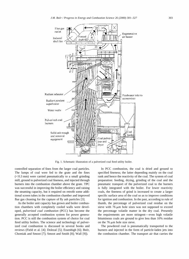
Fig. 1. Schematic illustration of a pulverized coal fired utility boiler.
coal from the mill to the burners is a small fraction of thetotal combustion air mainly because its temperature islimited to about 1008C for reasons of safety against ignitionand explosion in the mill and the transport pipeline betweenthe mill and the burners. Upon injection into the combustionchamber, the coal particle-laden jet entrains hot combustionproducts, which raises its temperature and assists the igni-tion of the cloud of coal particles. The rest of the combustionair, which can be more strongly preheated, is injected sepa-rately and admixed with the burning fuel jet in the combus-tion chamber. A schematic illustration of a PCC boiler isshown in Fig. 1. The combustion chamber is typically ofparallelepiped shape; the dimensions of a 300 MW coal-fired boiler would approximately be 15× 15 m2 of cross-sectional area and 45–50 m in height. The combustionchamber walls are completely cooled by steam generatingtubes. The particles burn in a mode in which both externaldiffusion of oxygen to the particle surface and chemisorp-tion of the oxygen at the particle surface and in the pores ofthe solid char play roles in determining the progress ofcombustion, with diffusion controlling the burning rate oflarger particles at the higher temperatures, and chemicalkinetics controlling the burning rate of the small particlesas the char burns out in the tail end of the flame. A compre-hensive review of the fundamentals of pulverized coalcombustion is presented by Essenhigh [6].
Burners are mixing devices designed to ensure ignition,flame stability, and complete burnout of the coal along itspath in the combustion chamber. As the pulverized coalparticles burn, the flame transfers heat, mainly by thermalradiation, to the steam cooled tube-walls of the boiler. Thelast few percentages of the residual carbon in the char burnsin an environment of depleted O2 concentration and reducedtemperature before the fly ash leaves the combustion cham-ber and enters the pass of convective heat exchangers. Thedesign of the combustion chamber has to provide for suffi-
cient residence time of the burning particle to completecombustion, and for the cooling of the fly ash to below its“softening temperature” to prevent the build up of ashdeposits on heat exchanger surfaces.
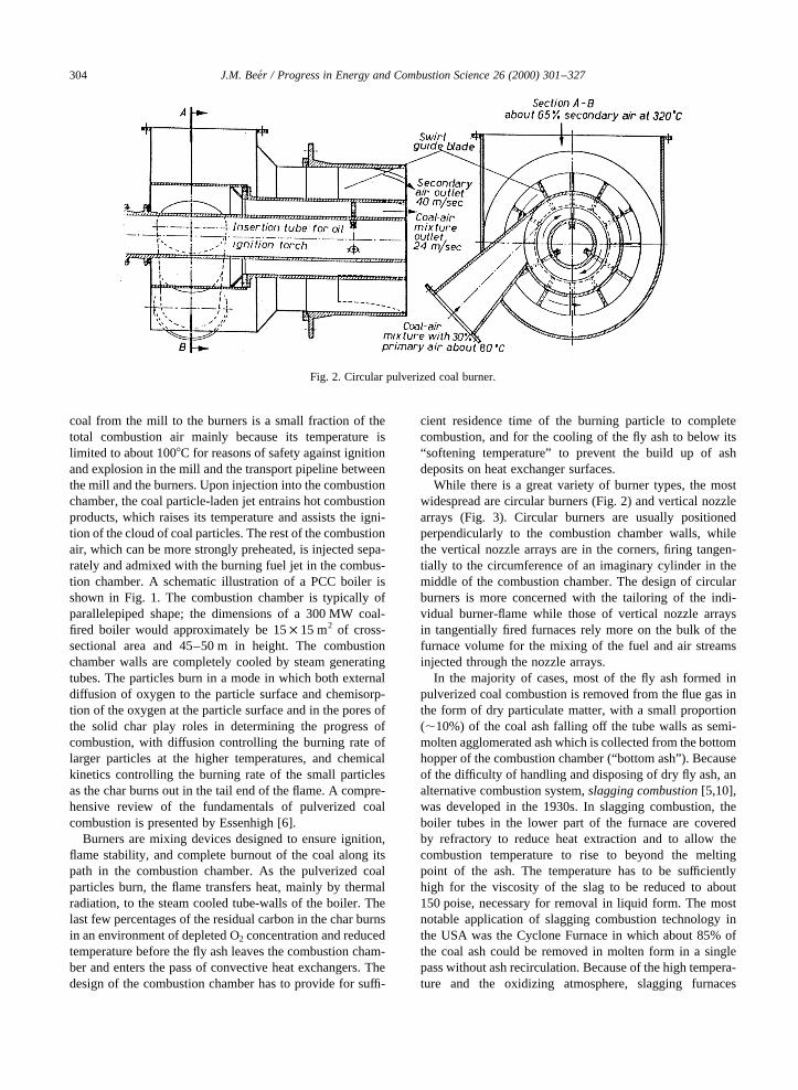
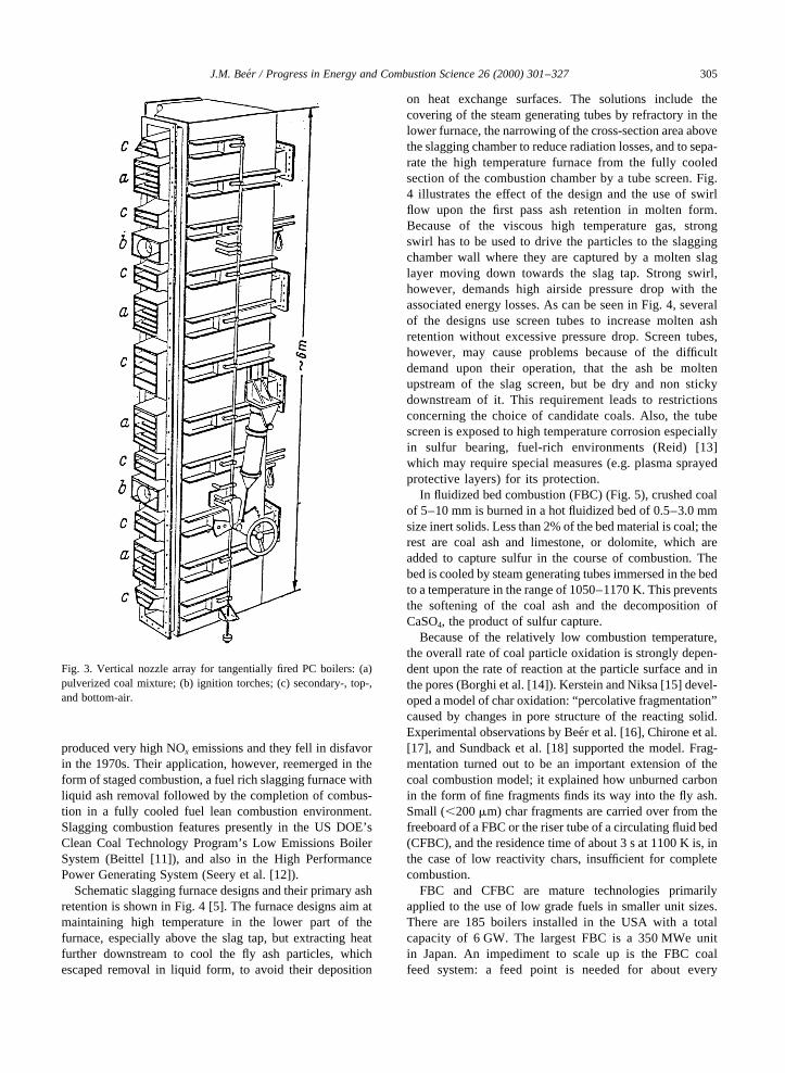
While there is a great variety of burner types, the mostwidespread are circular burners (Fig. 2) and vertical nozzlearrays (Fig. 3). Circular burners are usually positionedperpendicularly to the combustion chamber walls, whilethe vertical nozzle arrays are in the corners, firing tangen-tially to the circumference of an imaginary cylinder in themiddle of the combustion chamber. The design of circularburners is more concerned with the tailoring of the indi-vidual burner-flame while those of vertical nozzle arraysin tangentially fired furnaces rely more on the bulk of thefurnace volume for the mixing of the fuel and air streamsinjected through the nozzle arrays.
In the majority of cases, most of the fly ash formed inpulverized coal combustion is removed from the flue gas inthe form of dry particulate matter, with a small proportion(,10%) of the coal ash falling off the tube walls as semi-molten agglomerated ash which is collected from the bottomhopper of the combustion chamber (“bottom ash”). Becauseof the difficulty of handling and disposing of dry fly ash, analternative combustion system,slagging combustion[5,10],was developed in the 1930s. In slagging combustion, theboiler tubes in the lower part of the furnace are coveredby refractory to reduce heat extraction and to allow thecombustion temperature to rise to beyond the meltingpoint of the ash. The temperature has to be sufficientlyhigh for the viscosity of the slag to be reduced to about150 poise, necessary for removal in liquid form. The mostnotable application of slagging combustion technology inthe USA was the Cyclone Furnace in which about 85% ofthe coal ash could be removed in molten form in a singlepass without ash recirculation. Because of the high tempera-ture and the oxidizing atmosphere, slagging furnaces
J.M. Beer / Progress in Energy and Combustion Science 26 (2000) 301–327304
Fig. 2. Circular pulverized coal burner.
produced very high NOx emissions and they fell in disfavorin the 1970s. Their application, however, reemerged in theform of staged combustion, a fuel rich slagging furnace withliquid ash removal followed by the completion of combus-tion in a fully cooled fuel lean combustion environment.Slagging combustion features presently in the US DOE’sClean Coal Technology Program’s Low Emissions BoilerSystem (Beittel [11]), and also in the High PerformancePower Generating System (Seery et al. [12]).
Schematic slagging furnace designs and their primary ashretention is shown in Fig. 4 [5]. The furnace designs aim atmaintaining high temperature in the lower part of thefurnace, especially above the slag tap, but extracting heatfurther downstream to cool the fly ash particles, whichescaped removal in liquid form, to avoid their deposition
on heat exchange surfaces. The solutions include thecovering of the steam generating tubes by refractory in thelower furnace, the narrowing of the cross-section area abovethe slagging chamber to reduce radiation losses, and to sepa-rate the high temperature furnace from the fully cooledsection of the combustion chamber by a tube screen. Fig.4 illustrates the effect of the design and the use of swirlflow upon the first pass ash retention in molten form.Because of the viscous high temperature gas, strongswirl has to be used to drive the particles to the slaggingchamber wall where they are captured by a molten slaglayer moving down towards the slag tap. Strong swirl,however, demands high airside pressure drop with theassociated energy losses. As can be seen in Fig. 4, severalof the designs use screen tubes to increase molten ashretention without excessive pressure drop. Screen tubes,however, may cause problems because of the difficultdemand upon their operation, that the ash be moltenupstream of the slag screen, but be dry and non stickydownstream of it. This requirement leads to restrictionsconcerning the choice of candidate coals. Also, the tubescreen is exposed to high temperature corrosion especiallyin sulfur bearing, fuel-rich environments (Reid) [13]which may require special measures (e.g. plasma sprayedprotective layers) for its protection.
In fluidized bed combustion (FBC) (Fig. 5), crushed coalof 5–10 mm is burned in a hot fluidized bed of 0.5–3.0 mmsize inert solids. Less than 2% of the bed material is coal; therest are coal ash and limestone, or dolomite, which areadded to capture sulfur in the course of combustion. Thebed is cooled by steam generating tubes immersed in the bedto a temperature in the range of 1050–1170 K. This preventsthe softening of the coal ash and the decomposition ofCaSO4, the product of sulfur capture.
Because of the relatively low combustion temperature,the overall rate of coal particle oxidation is strongly depen-dent upon the rate of reaction at the particle surface and inthe pores (Borghi et al. [14]). Kerstein and Niksa [15] devel-oped a model of char oxidation: “percolative fragmentation”caused by changes in pore structure of the reacting solid.Experimental observations by Bee´r et al. [16], Chirone et al.[17], and Sundback et al. [18] supported the model. Frag-mentation turned out to be an important extension of thecoal combustion model; it explained how unburned carbonin the form of fine fragments finds its way into the fly ash.Small (,200mm) char fragments are carried over from thefreeboard of a FBC or the riser tube of a circulating fluid bed(CFBC), and the residence time of about 3 s at 1100 K is, inthe case of low reactivity chars, insufficient for completecombustion.
FBC and CFBC are mature technologies primarilyapplied to the use of low grade fuels in smaller unit sizes.There are 185 boilers installed in the USA with a totalcapacity of 6 GW. The largest FBC is a 350 MWe unitin Japan. An impediment to scale up is the FBC coalfeed system: a feed point is needed for about every
J.M. Beer / Progress in Energy and Combustion Science 26 (2000) 301–327 305
Fig. 3. Vertical nozzle array for tangentially fired PC boilers: (a)pulverized coal mixture; (b) ignition torches; (c) secondary-, top-,and bottom-air.

3 MWe throughput. The advantage of the CFBC overthe FBC is that it requires fewer feed points due tothe smaller cross-sectional area of the bed, and henceit is more easily scaleable to higher outputs. Also, for agiven percentage sulfur capture, CFBC requires a lowerCa/S feed ratio.
2. Pollutant emission control
In the 1970s, applied combustion research has taken aturn from high output, high intensity combustion towardscombustion process modifications for reduced pollutantemissions. The combustion generated pollutants of concern
J.M. Beer / Progress in Energy and Combustion Science 26 (2000) 301–327306
Fig. 4. Primary ash retention in various slagging furnace designs [5].
Fig. 5. Reactions in fluidized coal combustion [19].

J.M. Beer / Progress in Energy and Combustion Science 26 (2000) 301–327 307
Fig. 6. Combustion generated pollutant emissions.
Fig. 7. Chemical pathways of NOx formation and destruction [20].

were oxides of sulfur, nitrogen and carbon, and fine organicand inorganic particulates (Fig. 6).
Sulfurin the coal will oxidize to SO2 with a small fractionof the SO2 (about 1–2%) oxidizing further to SO3. Theformation of SO3 can be mitigated by very low excess O2
combustion (,0.5% EO2). The usual methods of sulfurcapture in the combustion process involve the reactions ofa sorbent such as calcined limestone, CaO, with SO2 to
produce CaSO4, a stable, disposable solid waste. However,in the high temperature fuel-lean environment of pulverizedcoal flames�Tpeak < 2000 K�; CaSO4 is unstable; it decom-poses, leaving flue gas desulfurization as the viable option ofsulfur capture from pulverized coal combustion.
The development of fluidized bed combustion providedthe opportunity to effectively retain sulfur in the combustionprocess because CaSO4 is stable at the FBC operatingtemperature of 1050–1170 K [19]. One of the difficultiesof FBC technology is that it does not lend itself well toscale-up to the 700–1000 MW range, mainly because ofthe large number of feed points it requires to ensure theuniform distribution of the coal in the bed. In circulatingfluidized bed combustion, the gas velocities are higher thanin the conventional bubbling fluidized bed as the bed cross-sectional area for the same heat release rate is smaller. Thishelps to reduce the number of coal feed points, which is anoperational convenience. Also, smaller size limestone parti-cles can be used in the feed which improves the sulfurcapture and reduces the Ca/S mole ratio necessary for reach-ing a target value of sulfur capture.
Nitrogen oxidesas pollutants deserve special attentionbecause of their wide ranging effects on the environment,including contribution to acid rain, reduction of atmosphericvisibility, production of tropospheric ozone, and, in the caseof N2O, depletion of stratospheric ozone. It is also note-worthy that NOx emissions are well amenable to reductionby combustion process modifications (Bee´r [20]).
Nitric oxide, NO, is formed in fuel-lean flames by theattack of O atom on molecular nitrogen (“thermal NO”).In fuel-rich flames it forms via capture of N2 by hydrocarbonradicals, (“prompt NO”), and by the pyrolysis and oxidationof heterocyclic nitrogen compounds in coals and petroleumfuels (“fuel NO”). Fig. 7 illustrates chemical pathways ofnitrogen compound interconversions in fuel lean and fuelrich flames. Examination of the chemical reaction paths ofnitrogen oxides formation and destruction in flames led tothe formulation of guidelines for primary measures of NOx
emissions reduction in boilers:
• reducing the peak flame temperature by heat extraction,and/or by flue gas recirculation;
• diluting the reactant concentrations by flue gas or steammixed with gaseous fuels and recirculated burned gasmixed with the combustion air;
• staging the combustion air to produce fuel-rich/fuel-leansequencing favorable for the conversion of fuel boundnitrogen to N2; and
• staging the fuel so that the NO formed earlier in the flameis getting reduced by its reactions with hydrocarbon radi-cals (“NO reburning”) (Wendt et al. [21]).
The reduction of NOx emission by combustion processmodification, a science based technology, has beensuccessfully applied in industry. More than 188 GW ofelectric power generating capacity currently in operation
J.M. Beer / Progress in Energy and Combustion Science 26 (2000) 301–327308
Table 1Capacities of coal-fired units fitted with primary combustionmeasures for NOx reduction currently in use world wide (afterIEA coal research, 1995)
Country MWe
Austria 1675Belgium 555Canada 9065China 70Denmark 4585Finland 1765Germany 30,332Hong Kong 1030Ireland 305Italy 3495Japan 15,320Koreas(s) 1060Malaysia 600Netherlands 4340Sweden 715Taiwan 5825Ukraine 300UK 12,600USA 94,483
Total 188.665 GWe
Fig. 8. Low NOx burner schematic.
J.M. Beer / Progress in Energy and Combustion Science 26 (2000) 301–327 309
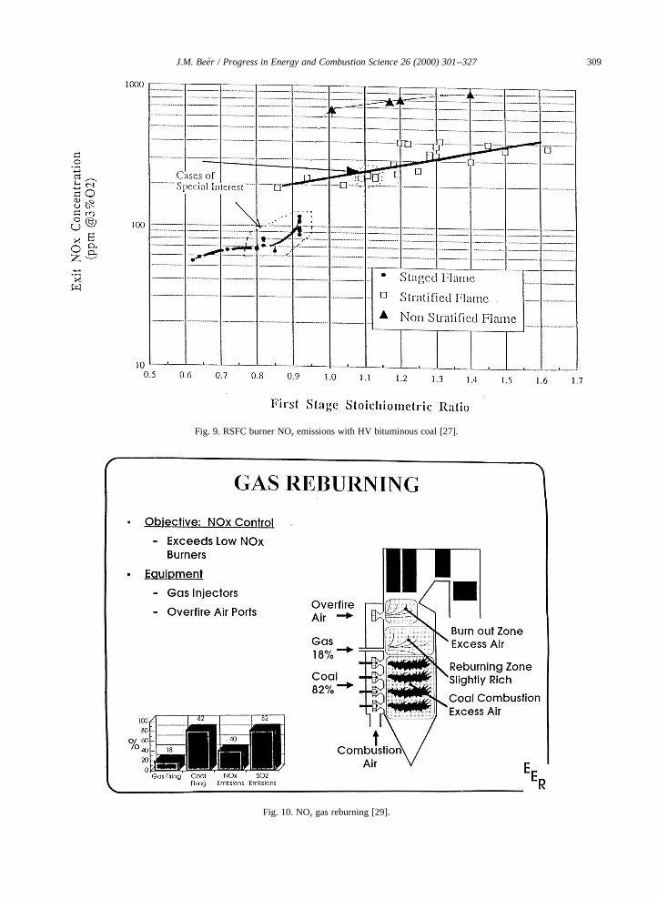
Fig. 9. RSFC burner NOx emissions with HV bituminous coal [27].
Fig. 10. NOx gas reburning [29].
internationally has been fitted by these “primary combustionmeasures” (Table 1 IEA [22]).
Low NOx burners(LNB) (Fig. 8) represent the most costeffective method of achieving reduced NOx emissions fromnew plant boilers, and also from existing boilers by retrofit.Air staging in these burners is achieved by the aerodynami-cally tailored mixing of the fuel jet with air streams suppliedthrough the burner, rather than by the use of over-fire air.
One of the problems of LNBs is the requirement of main-taining a fuel-rich environment close to the burner for thepyrolysis reactions to run their course, followed by theadmixing of the residual combustion air to completecombustion. An example of an engineering solution of thisproblem based on first principles is the radially stratifiedflame core burner (RSFC). The process of turbulence damp-ing through radial density stratification in rotating flowsdemonstrated by Emmons and Ying [23], and Chigier etal. [24] has been employed in the design of this LNB.Premature air-fuel mixing is prevented by the damping ofturbulence in the near burner region followed by the vigor-ous admixing of the residual burner air issuing from theouter annulus of a triple annular burner. Toqan et al. [25],Shiadeh et al. [26], and Barta et al. [27] reported NOx emis-sions achieved with the RSFC burner burning natural gas,heavy fuel oil, and coal, respectively, in the 1.5 MWth MITcombustion Research Facility. In Fig. 9, measured NOx
concentrations are plotted for pulverized coal [27]. The
straight line in the middle of the graph represents the casewithout external air staging. The top line refers to uncon-trolled conditions, and the lowest line to the use of the RSFCburner with over-fire air.
The RSFC burner has been scaled up and commercializedby ABB under license from MIT. LaFlesh et al. [28] haverecently given an update on ABB-CE’s RSFC Low NOx wallburner technology.
In “NO reburning,” the secondary fuel is usually naturalgas (Fig. 10) [29],but fuel oil or even coal can also be used.In the latter case, the coal volatiles are the main reactants,but carbonaceous solids may also react to reduce NO to N2
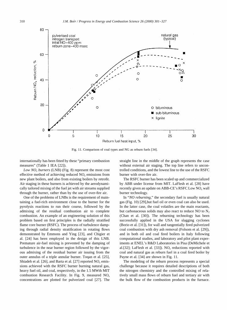
(Chan et al. [30]). The reburning technology has beensuccessfully applied in the USA for slagging cyclones(Borio et al. [31]), for wall and tangentially fired pulverizedcoal combustion with dry ash removal (Folsom et al. [29]),and in both oil and coal fired boilers in Italy followingcomputational studies, and laboratory and pilot plant exper-iments at ENEL’s R&D Laboratories in Pisa (DeMichele etal.[32]; LaFlesh et al. [33]). NOx reductions reported withcoal and natural gas as reburn fuel in a coal fired boiler byPayne et al. [34] are shown in Fig. 11.
The modeling of the reburn process represents a specialchallenge because it requires detailed descriptions of boththe nitrogen chemistry and the controlled mixing of rela-tively small mass flows of reburn fuel and tertiary air withthe bulk flow of the combustion products in the furnace.
J.M. Beer / Progress in Energy and Combustion Science 26 (2000) 301–327310
Fig. 11. Comparison of coal types and NG as reburn fuels [34].

Ehrhardt et al. [35] have developed a model in whichfollowing a CFD calculation of the spatial distributions offlow, major species-concentrations, and temperature, thecombustion space is subdivided into a relatively smallnumber (say one hundred) of volume zones which thenpermit the application of more detailed chemistry thanwould have been possible in CFD models. Comparisonwith experiment showed good agreement with computationsfor an axisymmetric oil fired reburn system [35].
Because of the low combustion temperature in fluidizedcombustion, the NO is formed mainly by the conversion of
coal-nitrogen, a process which lends itself for minimizingemission by the application of staged air introduction (Gibbset al. [36]). However, a difficulty due to the low combustiontemperature is that nitrous oxide, N2O, an intermediateproduct of NO formation, survives and is emitted fromFBC at concentrations ranging from 40 to 100 ppm [22].Nitrous oxide is a specially unpleasant pollutant; it is agreenhouse gas which also depletes stratospheric ozone.The raising of the gas temperature before the convectivesection of the boiler to above 1200 K could eliminate N2Oemissions, but the temperature rise adversely affects sulfurcapture in the fluidized bed (Tullin et al. [37]). It is note-worthy that pressurized fluidized beds also emit N2O, exceptthe second generation pressurized fluidized bed in which thegas temperature is raised by a topping combustor beforeentry to the gas turbine, thereby eliminating the N2O inthe combustion products [38].
In gas turbine(GT) applications, large amount of excessair is used to cool the combustion products before entry tothe gas turbine to a temperature limited by the structuralintegrity of gas turbine blades. In the conventional methodof combustion, the fuel and air are separately injected intothe combustor and mix in the course of combustion (diffu-sion flame). This process is prone to the formation of ther-mal NO because of the near stochiometric conditions whichprevail on the boundaries of fuel-rich and fuel-lean eddies insuch flames. To overcome this problem, the fuel gas and airare premixed prior to their entry to the combustor creating astrongly fuel-lean mixture corresponding to the combustorexit gas temperature (presently about 1573 K).
This so called ultralean premixed combustion gives verylow NOx emissions, typically less than 15 ppm at 15% O2,with natural gas as fuel, but is left with the problem of flamestability. The latter is generally solved by the injection of asmall percentage of the fuel, say 10%, to produce a fuel jetpilot flame as a stable source of ignition. Fig. 12 illustratesthe opportunities and some of the problems of ultraleanpremix combustion (Maghon et al. [39]). The figure shows
J.M. Beer / Progress in Energy and Combustion Science 26 (2000) 301–327 311
Fig. 12. NOx and CO emissions; diffusion flames, partially,-andfully premixed combustion in gas turbines [39].
Fig. 13. ABB’s double cone GT combustor [41].

the measured variations of NOx and CO emission data asfunctions of the air/fuel ratio and of the adiabatic flametemperature of a natural-gas/air diffusion flame, and for92% and 100% premixing. In the case of 92% premixing,the rest of the fuel (8%) burns in the form of a pilot diffusionflame. NOx and CO emissions are very low in the range ofstate of the art turbine entry temperatures (1573 K), but theflame stability is not ensured without the pilot flame. As theair/fuel ratio increases, the CO emission rises steeply. Mostof the major gas turbine manufacturers are offering leanburn premix combustors capable of 15 ppm NOx (15% O2)dry or with minimal water injection (Bee´r) [40]. As exam-ples, ABB’s Double Cone burner is illustrated in Fig. 13(Sattlemayer et al. [41]), and Siemens’ KWU in Fig. 14(Becker et al. [42]). As new materials permit raising theturbine inlet gas temperature beyond 1800 K, the opportu-nity to reduce NOx emissions by lean premixed combustionwill become limited. This will present a new challenge tocombustion R&D in gas turbine applications.
3. Coal mineral matter transformations
The transformation of coal mineral matter duringcombustion has been the subject of a rich literature, severaltexts, and conference proceedings, e.g. CEGB MarchwoodConf. [43], Reid [13], Wall [44], Couch [45], and Engnr.Found. Conferences [46–48].
A combination of computer controlled scanning electronmicroscopy and mathematical modeling made it possible tofollow the changes in the properties of the coal ash (particlesize, chemical composition, viscosity) during combustion ofthe coal particle, and to determine the propensity of the ashfor deposition on heat exchange surfaces in the boiler plant(Barta et al. [49]).
At the high peak temperatures of pulverized coal combus-tion (2000 K) and especially under the conditions of slag-ging combustion (liquid ash removal), the coal mineralmatter melts and partially vaporizes. The vaporization ofthe mineral matter in the flame is of great interest becauseits emission represents a health hazard due to the sub-micrometer size inorganic particulate formed on condensa-tion of the vaporized ash (Gumz [50]). Another part of thisinorganic vapor may condense on superheater tubes causingoperational problems. Experimentally determined fractionsof coal minerals which remained unvaporized at varioustemperatures are shown in Fig. 15 (Sarofim et al. [51]).
Environmental interest in the utilization of fly ash as anadditive to clinker in the cement making process drew atten-tion to the level of residual carbon in the ash, normallyrestricted to 5%. It has been the experience with some ofthe low NOx (staged air) combustion systems that the resi-dual carbon in the fly ash has risen well above this concen-tration. Examinations of the structure of residual carbonsamples by means of X-ray diffraction, optical reflectance,and high resolution transmission electron microscopy(HRTM) (Hurt and Hardesty [52], and Beeley et al. [53])have shown that the coal undergoes significant structuralchanges on the atomic and mesoscale leading tochanges in surface area or available surface sites asit passes through high temperature combustionregions. Reactivity measurements show a propensityfor deactivation, which correlates with the extent ofcrystalline order development as observed by HRTMfringe imaging. They also find that deactivationaffects more the more reactive vitrinite-rich sampleand argue that this is the reason for the small differ-ence between the reactivity of residual carbonsamples originating from vitrinite-rich and inertinite-rich coal.
4. Power cycles of high thermodynamic efficiency
Pollutant emission from electric power generating plantcan be further reduced by the improvement of the thermo-dynamic cycle of power generation. The power cycleschosen for discussion from a great variety of such schemesinclude:
• pulverized coal combustion (PCC) in supercritical steamboiler in a single Rankine cycle (e.g. 250 atm 3× 853 K);
• natural gas fired gas turbine–steam combined (Brayton–Rankine) cycle (GCC);
• indirectly coal and natural gas fired (air heater) combinedGT-steam cycles;
• pressurized fluidized bed (PFBC) without and withtopping combustor; and
• integrated gasification combined cycle (IGCC) with coal,refinery waste, or biomass as fuel.
J.M. Beer / Progress in Energy and Combustion Science 26 (2000) 301–327312
Fig. 14. Siemens’ low NOx GT combustor [42].

Pulverized coal fired supercritical steam boilershavebeen in use since the 1930’s but improvements in materialsand increasing demand for higher efficiency are making thissystem presently the choice of new coal fired utility plantworld-wide. The increase in efficiency is due to the highermean temperature of the heat addition as illustrated by theT–Sdiagram of a supercritical steam cycle in Fig. 16 (Bu¨ki[54]). Because of the increased moisture content of the highpressure steam at the last stages of the steam turbine, thesteam has to be reheated in the course of its expansion. Thereheat, single or double, is, however, chosen not only tosolve the problem of the reduced dryness fraction of thesteam but also to raise the thermodynamic efficiency ofthe power cycle. In the example, the thermodynamic meantemperature can be seen to increase from T1 for the basicsupercritical cycle with single superheat to Tu1 and Tu2 forsingle and double reheat, respectively. Comparison of
design parameters of a 300 MW subcritical steam cycleplant with a supercritical plant of the same performanceshows an efficiency gain of 1.7% with a fuel saving of50.000 t/y and a CO2 emission reduction of 137.000 t/y forthe supercritical unit (Table 2) (Hauser [55]).
The use of the supercritical boiler, however, carries impli-cations for the combustion process. The lower heat transferrate on the steam side of supercritical pressure boiler tubescompared to those at subcritical pressure demands spatiallymore uniform heat release in the combustion chamber, andthe higher surface temperature of the superheater andreheater tubes may cause increased tendency for coal ashdeposition.
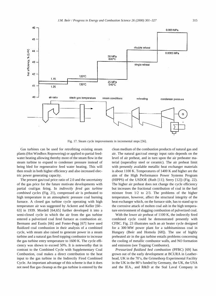
The Rankin cycle efficiency of a pulverized coal firedsteam plant can be increased in small steps to beyond45% using supercritical steam parameters as shown in Fig.17 (Schilling [56]).
J.M. Beer / Progress in Energy and Combustion Science 26 (2000) 301–327 313
Fig. 15. Vaporization of coal ash [51].

4.1. Gas turbine–steam combined cycles
Because of the complementary temperature ranges of theBrayton (1600–900 K) and Rankine (850–288 K) cycles,their combinations can produce significantly improved ther-modynamic cycle efficiency. A thermodynamic (tempera-ture–entropy diagram) representation of the increasedefficiency is shown in Fig. 18. In a more recent developmentof a reheat cycle (Meisl et al. [57]), in which additional fuelis injected downstream of the high pressure stage of the gas
turbine (Sequential Combustion), combined cycle efficiencyapproaching 60% is achieved with ultralean premix low NOx
combustors.Because of the low first cost and high efficiency, GCC is
highly competitive with PCC despite the gas/coal pricedifferential today and the uncertainty of future gas prices.The comparison of the levelized costs of electricity of a500 MW coal and 225 MW gas fired combined cycle plantfor 60% and 100% capacity factors in 2000 and 2010 areshown in Fig. 19a and b, respectively (Beamon and Wade[58]). As can be seen from this comparison, the presentdifference in cost of electricity between PCC and GCC isreduced at high capacity factors, and according to theseestimates, the difference disappears in 2010 due to the risinggas prices and the expected reduction in the cost of PCC.
When coal or residual fuel oil is added as a supplementaryfuel in the Heat Recovery Steam Generator of a GCC plant(Fig. 20), there is considerable gain in operational flexibil-ity, albeit at the expense of a small reduction in the cycleefficiency. The gas turbine exhaust gas contains typically12–16% O2, depending on the thermal load. At stronglydepleted O2 concentrations, combustion stability and carbonburn-out of the supplementary fuel may present problems,while at higher O2 levels and gas turbine exhaust gastemperatures, the NOx emission needs special attention(Smart and deKamp [59]).
J.M. Beer / Progress in Energy and Combustion Science 26 (2000) 301–327314
Fig. 16.T–Sdiagram of a supercritical steam cycle [54]: left) reversible supercritical steam cycle with double reheat; right) supercritical steamturbine expansion lines for cases of single and double reheat.
Table 2Design parameters for a 300 MWe coal-fired plant (Ha¨user [55])
Subcritical Supercritical
Steam generator Controlled OnceCirculation Through
Steam turbine Two casings Three casingsSteam pressure (MPa) 16.5 25Steam temperature (8C) 540 540Reheat temperature 1 (8C) 540 566Feedwater temperature (8C) 261 288Cooling water temperature (8C) 0027 27Heat rate (kJ/kWh) 7955 7522Net efficiency (LHV) (%) 39.4 41.1Coal consumption (t/y) 874,000 826,000
Gas turbines can be used for retrofitting existing steamplants (Hot Windbox Repowering) or applied to partial feed-water heating allowing thereby more of the steam flow in thesteam turbine to expand to condenser pressure instead ofbeing bled for regenerative feed water heating. This willthen result in both higher efficiency and also increased elec-tric power generating capacity.
The present gas/coal price ratio of 2.0 and the uncertaintyof the gas price for the future motivate developments withpartial coal/gas firing. Inindirectly fired gas turbinecombined cycles(Fig. 21), compressed air is preheated tohigh temperature in an atmospheric pressure coal burningfurnace. A closed gas turbine cycle operating with hightemperature air was suggested by Ackeret and Keller [60–63] in 1939. Mordell [64,65] further developed it into asemi-closed cycle in which the air from the gas turbineentered a pulverized coal fired furnace as combustion air.Bermann and Eustis [66] and Foster-Pegg [67] have usedfluidized coal combustion in their analysis of a combinedcycle, with steam also raised to generate power in a steamturbine and a natural gas fired topping combustor to increasethe gas turbine entry temperature to 1600 K. The cycle effi-ciency was shown to exceed 50%. It is noteworthy that incontrast to the Combined Cycle with Supplementary CoalCombustion, coal makes a direct contribution to the heatinput to the gas turbine in the Indirectly Fired CombinedCycle. An important advantage of this scheme is that it doesnot need flue gas cleanup as the gas turbine is entered by the
clean medium of the combustion products of natural gas andair. The natural gas/coal energy input ratio depends on thelevel of air preheat, and in turn upon the air preheater ma-terial (superalloy steel or ceramic). The air preheat limitwith presently available metallic heat exchanger materialsis about 1100 K. Temperatures of 1400 K and higher are theaim of the High Performance Power Systems Program(HIPPS) of the USDOE (Ruth [11]; Seery [12]) (Fig. 22).The higher air preheat does not change the cycle efficiencybut increases the fractional contribution of coal in the fuelmixture from 1/2 to 2/3. The problems of the highertemperature, however, affect the structural integrity of theheat exchanger which, on the furnace side, has to stand up tothe corrosive attack of molten coal ash in the high tempera-ture environment of slagging combustion of pulverized coal.
With the lower air preheat of 1100 K, the indirectly firedcombined cycle could be demonstrated presently withCFBC. Fig. 23 illustrates such an air heater cycle designedfor a 300 MW power plant for a subbituminous coal inHungary (Bee´r and Homola [68]). The use of highlypreheated air in the gas turbine entails problems concerningthe cooling of metallic combustor walls, and NO formationand emission (see Topping Combustor).
Pressurized fluidized bed combustion(PFBC) [69] hasgrown out of the early development at BCURA in Leather-head, UK in the 70’s, the Grimethorp Experimental Facilityin the UK in the 80’s funded by Germany, the UK, the USAand the IEA., and R&D at the Stal Laval Company in
J.M. Beer / Progress in Energy and Combustion Science 26 (2000) 301–327 315
Fig. 17. Steam cycle improvements in incremental steps [56].

Sweden in preparation of the 70 MWe demonstration plantto be built for the American Electric Power Co. Miniplantsto study environmental performance of PFBC’s weresuccessfully operared at Exxon in Linden, New Jersey[70] and at the USDOE Argonne National Laboratory[71]. Massimilla’s group at the University of Naples(Poletto [72]), and Jahkola’s group at the University ofHelsinki [73] have contributed valuably to the fundamentalunderstanding of fluid flow, heat transfer, and combustionprocesses in pressurized fluid bed combustors.
A schematic of PFBC is shown in Fig. 24. Compared toFBC, the heat release rate per unit bed area in PFBC isseveral times higher and the bed height is 3–4 m insteadof the typical bed height of 1 m in FBC. Under atmosphericpressure conditions, the bed height is limited by the accep-table pressure drop of about 100 mbar across the bed. In the
PFBC-GT Cycle, the 300 mbar pressure drop represents lessthan 3% of the total pressure ratio. A consequence of theincreased bed height is a larger carbon inventory in the bedand lower NO emission due to the reduction of the formedNO by solid carbon in the bed (Chan et al. [30]). However,the high carbon load does not reduce the emission of theN2O, which is still stable at the relatively low temperature ofthe PFBC. The low temperature is unfavorable also from thepoint of view of combined cycle thermodynamics; it is toolow for an efficient gas turbine application.
The thermodynamic efficiency of the PFBC combinedcycle units in operation is about 40%. Further increases inefficiency can be obtained by raising the turbine inlettemperature using a topping combustor.
The second generation of PFBC(Fig. 25) (Robertson etal. [74]) is a response to the needs of raising the gas
J.M. Beer / Progress in Energy and Combustion Science 26 (2000) 301–327316
Fig. 18. A thermodynamic representation of the improved efficiency of combined cycle plants [58]: (a) steam (Rankine cycle); (b) gas-turbine(Brayton cycle); and (c) unfired combined cycle.

J.M. Beer / Progress in Energy and Combustion Science 26 (2000) 301–327 317
Fig. 19. Comparison of cost of electricity for PC and GCC plants in 2000 and 2010 at 60% and 100% capacity [58].
Fig. 20. Combined cycle with fired HRSG.

temperature at the inlet to the gas turbine. In this cycle, coal,usually in the form of coal-water slurry, is injected into apressurized carbonizer where it undergoes mild gasificationto produce a low calorific value gas and char. The char is
burned in a pressurized circulating fluidized bed (PCFBC)with high excess air, and the flue gas is cleaned of particu-lates and alkali at high temperature. Sulfur is captured in thePCFBC by additive dolomite. The fuel gas from the
J.M. Beer / Progress in Energy and Combustion Science 26 (2000) 301–327318
Fig. 21. Indirectly fired gas turbine combined cycle (CFBC air heater cycle with topping combustor) [66].
Fig. 22. HIPPS plant schematic [11,12].

carbonizer is cleaned of sulfur in the fluidized bed carbon-izer, and of particulates and alkali by hot gas cleanup. It isthen injected into the topping combustor where it raises thetemperature at the inlet to the gas turbine to 1623 K. Thistemperature rise increases the cycle efficiency to about 47%.Further improvements in efficiency can be obtained by theapplication of advanced gas turbine technology, and on thesteam side, by supercritical steam parameters with hightemperature double reheat. An additional advantage of thiscycle is that the N2O emission is eliminated because the N2Oformed in the pressurized fluidized combustor decomposes
at the elevated temperature in the Topping Combustor (Bee´rand Garland [38]).
4.2. The topping combustor
Because the air entering the combustor is at 1144 K ratherthan the usual 644 K for gas turbines, the conventional typeof combustor is not suitable. Both the emissions and coolingproblems preclude the use of conventional designs. An allmetallic multiannular combustor (MASB) patented by Bee´r[75] and developed by Westinghouse (Fig. 26) solves the
J.M. Beer / Progress in Energy and Combustion Science 26 (2000) 301–327 319
Fig. 23. Schematic of a 300 MW CFB air heater combined cycle for hungarian lignite with natural gas topping combustor [68].
Fig. 24. Pressurized fluidized bed combined cycle.

cooling problem by creating thick layers of gas flow over theleading edges of overlapping concentric annular passages inthe combustor. Due to the high convective heat transferrates, the temperature difference between the high alloymetal combustor wall and the 1144 K PFBC exhaust gasis less than 200 K, even at 1625 K combustor outlettemperature.
The mixing of fuel and air follows the Rich-Fast Quench-
Lean sequence which gives very low NOx emissions, withless than 10% of the fuel nitrogen in the syngas converted toNO, and has a high combustion efficiency of 99.9%. TheMASB pressure drop is less than 1% [38].
An additional demand of the topping combustor is that forcold start-up it has to be capable of operation with naturalgas as a fuel. Experiments carried out by Westinghouseunder a DOE Contract in 1986 using a 254 mm (1000)
J.M. Beer / Progress in Energy and Combustion Science 26 (2000) 301–327320
Fig. 25. Second generation PFBC with topping combustor [74].
Fig. 26. Multi annular swirl burner (MASB) topping combustor [75].
diameter MASB, with 1034 K (14008F) combustion air andburning natural gas yielded wall temperatures less than100K higher than the air temperature. The condition of thecombustor was excellent even though the calculated richzone adiabatic temperature was 2458 K (39648F). It hasto be verified experimentally, however, that these favor-able results hold for the scaled-up, 457 mm (1800)combustor in which radiative heat transfer to thecombustor walls is expected to increase on account ofthe higher gas emissivity.
4.3. Integrated gasification combined cycle
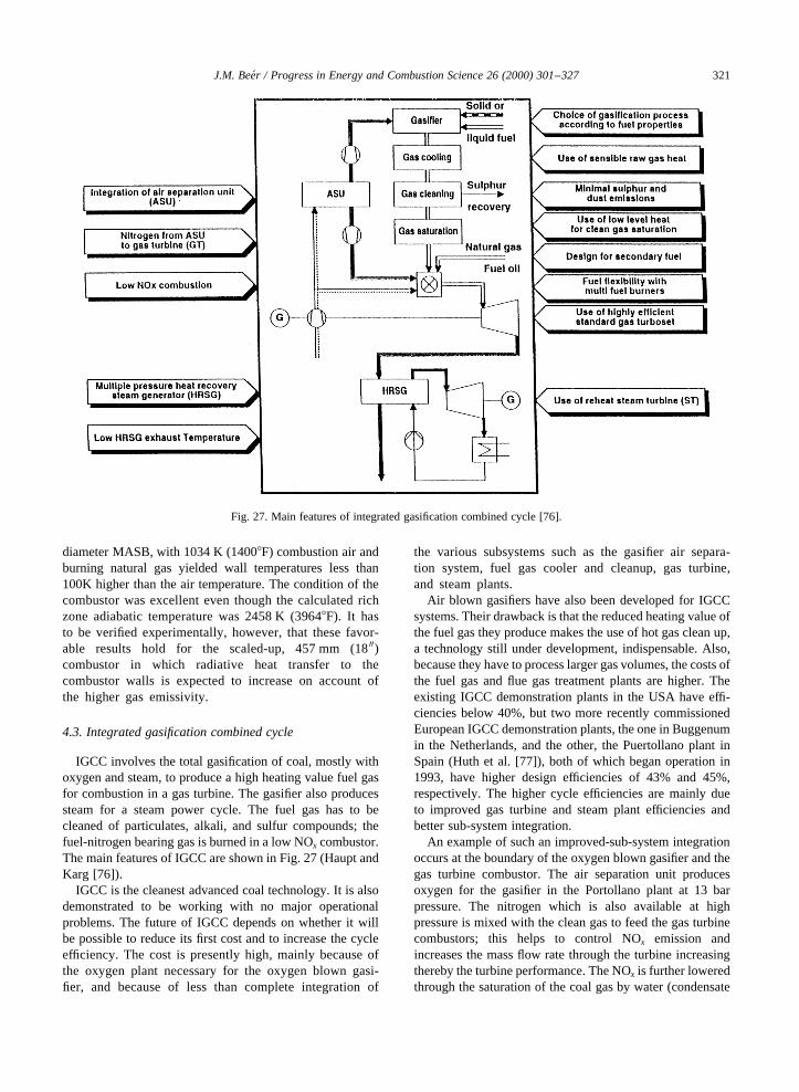
IGCC involves the total gasification of coal, mostly withoxygen and steam, to produce a high heating value fuel gasfor combustion in a gas turbine. The gasifier also producessteam for a steam power cycle. The fuel gas has to becleaned of particulates, alkali, and sulfur compounds; thefuel-nitrogen bearing gas is burned in a low NOx combustor.The main features of IGCC are shown in Fig. 27 (Haupt andKarg [76]).
IGCC is the cleanest advanced coal technology. It is alsodemonstrated to be working with no major operationalproblems. The future of IGCC depends on whether it willbe possible to reduce its first cost and to increase the cycleefficiency. The cost is presently high, mainly because ofthe oxygen plant necessary for the oxygen blown gasi-fier, and because of less than complete integration of
the various subsystems such as the gasifier air separa-tion system, fuel gas cooler and cleanup, gas turbine,and steam plants.
Air blown gasifiers have also been developed for IGCCsystems. Their drawback is that the reduced heating value ofthe fuel gas they produce makes the use of hot gas clean up,a technology still under development, indispensable. Also,because they have to process larger gas volumes, the costs ofthe fuel gas and flue gas treatment plants are higher. Theexisting IGCC demonstration plants in the USA have effi-ciencies below 40%, but two more recently commissionedEuropean IGCC demonstration plants, the one in Buggenumin the Netherlands, and the other, the Puertollano plant inSpain (Huth et al. [77]), both of which began operation in1993, have higher design efficiencies of 43% and 45%,respectively. The higher cycle efficiencies are mainly dueto improved gas turbine and steam plant efficiencies andbetter sub-system integration.
An example of such an improved-sub-system integrationoccurs at the boundary of the oxygen blown gasifier and thegas turbine combustor. The air separation unit producesoxygen for the gasifier in the Portollano plant at 13 barpressure. The nitrogen which is also available at highpressure is mixed with the clean gas to feed the gas turbinecombustors; this helps to control NOx emission andincreases the mass flow rate through the turbine increasingthereby the turbine performance. The NOx is further loweredthrough the saturation of the coal gas by water (condensate
J.M. Beer / Progress in Energy and Combustion Science 26 (2000) 301–327 321
Fig. 27. Main features of integrated gasification combined cycle [76].
from the steam cycle) heated up by the sensible heat of thecompressed air (673 K) at the compressor outlet.
Even with these improved cycle efficiencies, however,IGCC plants are presently not competitive with otheradvanced coal burning systems such as PCC fired super-critical steam plants because of their higher installationcost. Nevertheless, there are further considerations thatmay, in the future, tilt the balance in favor of IGCCapplications:
• IGCC lends itself for the efficient removal of CO2 fromthe high-pressure fuel gas (Pruschek et al. [78]).
• By broadening the fuel supply to the strongly increasingvolume of Refinery Wastes (heavy residual oils, petro-leum coke, Orimulsion), IGCC could become attractivefor clean and efficient Central Power Generation by usingfuels of very low or even “negative” cost (the waste fuelcost is negative if it stands against the cost of disposal(Empsperger and Karg [79])).
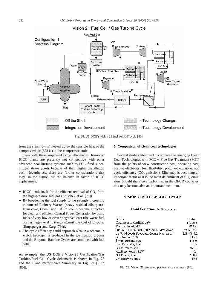
• The cycle efficiency could approach 60% in a scheme inwhich hydrogen is produced in the gasification processand the Brayton–Rankine Cycles are combined with fuelcells.
An example, the US DOE’s Vision21 Gasification/GasTurbine/Fuel Cell Cycle Schematic is shown in Fig. 28and the Plant Performance Summary in Fig. 29 (Ruth[80]).
5. Comparison of clean coal technologies
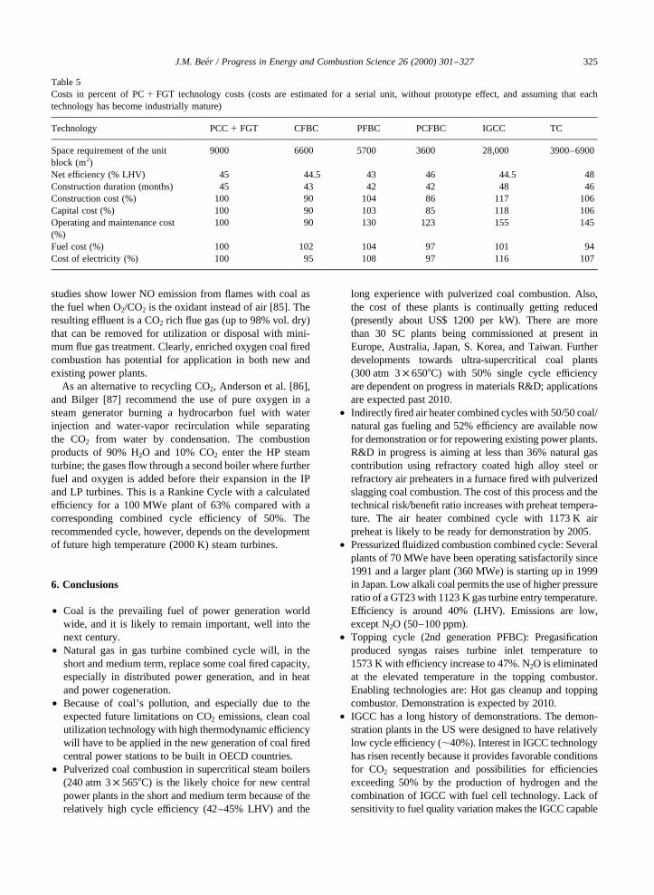
Several studies attempted to compare the emerging CleanCoal Technologies with PCC1 Flue Gas Treatment (FGT)from the points of view construction cost, operating cost,cost of electricity, fuel flexibility, pollutant emission, andcycle efficiency (CO2 emission). Efficiency is becoming animportant factor as it is the main determinant of CO2 emis-sion. Should there be a carbon tax in the OECD countries,this may become also an important cost item.
J.M. Beer / Progress in Energy and Combustion Science 26 (2000) 301–327322
Fig. 28. US DOE’s vision 21 fuel cell/GT cycle [80].
Fig. 29. Vision 21 projected performance summary [80].

For a comparison of these technologies, it is alsoimportant to forecast the development of some enablingtechnologies such as new superalloys for gas turbine bladingand for superheaters of supercritical steam boilers.
It is generally agreed that PCC1 FGT has an edge overthe coal fired combined cycle systems in the short andmedium term mainly because it is a mature technologyand also because competition and R&D in recent yearshas reduced its first cost to below US$ 1200 per kW installedcapacity.
Potential efficiencies of PCC, PFBC and IGCC as a func-tion of gas turbine inlet temperature are illustrated in Fig. 30(Lovis et al. [81]; Couch [82]). As the GT inlet temperaturerises, so does the combined cycle efficiency (the cycle effi-ciency increases about 2% for 100 K rise in gas turbine inlettemperature); the single cycle PCC remains, of course, unaf-fected. The diagram shows that PCC with supercriticalsteam promises comparable efficiency to those of the coalfired combined cycle systems. Table 3 contains data aboutthe number and type of coal fired utility plants underconstruction world wide (based on Couch [82]). Clearlythe great majority of these plants are PCC with supercriticalsteam boilers.
Comparisons of environmental performance data at fullload estimated by Delot et al. [83] are shown in Table 4. Thelow temperature fluid bed systems, except of the secondgeneration PFBC with the topping combustor, have aproblem with N2O emission, while PCC may face somefuture regulation on fine particulate (PM 2.5) and HAP(e.g. mercury) emissions. IGCC is the potentially cleanestof the advanced coal fired cycles. It has the special advan-tage that it is amenable to the efficient capture of CO2 fromits high pressure syngas stream. This is further underlined bythe comparative illustration of environmental advantages ofadvanced power cycles in Fig. 31 [76].
Table 5 has the data on costs relative to that of PCC1FGT [75]. It is noted that the advantage of supercriticalsteam for the efficiency affects more favorably the singlesteam cycles, PCC and CFBC, rather than the combinedcycles, because the latter benefit only partially fromadvanced steam parameters. Advances in gas turbines onthe other hand, lead to higher thermodynamic efficiencyfor the combined cycle plants (see Fig. 30). The prospectivenet efficiency of IGCC at 44.5% LHV seems somewhat low.Improved subsystem integration is promising IGCC effi-ciency close to 50% [76].
5.1. CO2 sequestration
In addition to current strategies of improving the effi-ciency of power generation, greenhouse gas emission canbe mitigated by CO2 sequestration (Herzog and Drake [84].The discussion of the technology of CO2 separation from theflue gas, and its disposal fall outside the scope of this review.There are, however, combustion measures, which byincreasing the CO2 concentration in the flue gas can reducethe costs associated with CO2 separation. One such tech-nique applicable to atmospheric pressure boiler-combustion,is oxygen enrichment of the combustion air and recirculationof high CO2 bearing flue gas through the burners. Thambimutu
J.M. Beer / Progress in Energy and Combustion Science 26 (2000) 301–327 323
Fig. 30. Comparison of high efficiency cycles; effect of GT inlet temperature [81,82].
Table 3Utility plants under construction 1997–2000 (based on IEA 1997data)
Total numberof plantsworldwide
42
Distribution bycombustionsystemPulverized coal 35 (29 supercrit. steam) 700–1000 MWeCFBC 3 (all subcrit. steam) 200–235 MWePFBC3 3 (1 supercrit. steam) 80–360 MWeIGCC 1 (subcrit. steam) 86 MWe

and Croiset [85] have shown that while such a scheme has tobear the cost of an air separation unit to produce the oxygen,there is some compensation in the reduced volume of thegas, which improves the boiler efficiency. Reduction of NOx
emission is also demonstrated [85].The adiabatic temperature is generally higher with O2
enriched air, but enrichment can be increased further with-out increased temperature for the case of recirculated CO2
due to its high heat capacity. Increased levels of O2 concen-tration may promote the conversion of organically boundnitrogen compounds to NO but the NO recirculated withthe flue gas is getting reduced in the flame. The laboratory
J.M. Beer / Progress in Energy and Combustion Science 26 (2000) 301–327324
Table 4Environmental performances at full load (mg/N m3, 6% O2)
Technology PCC1 FGT CFBC PFBC PCFBC IGCC TC
Nitrogen oxidesIntrinsic 800–1300 150–250 200–300 100–200 150–200 150–300Low-NOx burners 400a
In project 75–120 70–200 40–100With SCR 100–200 50–150Nitrous oxide 0–5 20–100 20–100 20–100 0–5 0–5Sulfur dioxide (1.0% S) b b b b
Intrinsic 2000 200 200 200 10–25 200Ca/S ratio 1.05 2.5 2.2 1.5 2.0With FGD 200Dust 50 50 50 10c 10c 10c
10c
a For new boilers 400 mg/N m3; from 500 to 700 mg/N m3 for existing ones.b With ceramic filters.c It is possible to reach emission levels below 200 mg/N m3 by simply increasing the quantity of limestone injected into the furnace, and
consequently the Ca/S ratio.
Fig. 31. Comparison of supply flows, emissions and byproducts of different 600 MW-class power plants [76].
studies show lower NO emission from flames with coal asthe fuel when O2/CO2 is the oxidant instead of air [85]. Theresulting effluent is a CO2 rich flue gas (up to 98% vol. dry)that can be removed for utilization or disposal with mini-mum flue gas treatment. Clearly, enriched oxygen coal firedcombustion has potential for application in both new andexisting power plants.
As an alternative to recycling CO2, Anderson et al. [86],and Bilger [87] recommend the use of pure oxygen in asteam generator burning a hydrocarbon fuel with waterinjection and water-vapor recirculation while separatingthe CO2 from water by condensation. The combustionproducts of 90% H2O and 10% CO2 enter the HP steamturbine; the gases flow through a second boiler where furtherfuel and oxygen is added before their expansion in the IPand LP turbines. This is a Rankine Cycle with a calculatedefficiency for a 100 MWe plant of 63% compared with acorresponding combined cycle efficiency of 50%. Therecommended cycle, however, depends on the developmentof future high temperature (2000 K) steam turbines.
6. Conclusions
• Coal is the prevailing fuel of power generation worldwide, and it is likely to remain important, well into thenext century.
• Natural gas in gas turbine combined cycle will, in theshort and medium term, replace some coal fired capacity,especially in distributed power generation, and in heatand power cogeneration.
• Because of coal’s pollution, and especially due to theexpected future limitations on CO2 emissions, clean coalutilization technology with high thermodynamic efficiencywill have to be applied in the new generation of coal firedcentral power stations to be built in OECD countries.
• Pulverized coal combustion in supercritical steam boilers(240 atm 3× 5658C) is the likely choice for new centralpower plants in the short and medium term because of therelatively high cycle efficiency (42–45% LHV) and the
long experience with pulverized coal combustion. Also,the cost of these plants is continually getting reduced(presently about US$ 1200 per kW). There are morethan 30 SC plants being commissioned at present inEurope, Australia, Japan, S. Korea, and Taiwan. Furtherdevelopments towards ultra-supercritical coal plants(300 atm 3× 6508C) with 50% single cycle efficiencyare dependent on progress in materials R&D; applicationsare expected past 2010.
• Indirectly fired air heater combined cycles with 50/50 coal/natural gas fueling and 52% efficiency are available nowfor demonstration or for repowering existing power plants.R&D in progress is aiming at less than 36% natural gascontribution using refractory coated high alloy steel orrefractory air preheaters in a furnace fired with pulverizedslagging coal combustion. The cost of this process and thetechnical risk/benefit ratio increases with preheat tempera-ture. The air heater combined cycle with 1173 K airpreheat is likely to be ready for demonstration by 2005.
• Pressurized fluidized combustion combined cycle: Severalplants of 70 MWe have been operating satisfactorily since1991 and a larger plant (360 MWe) is starting up in 1999in Japan. Low alkali coal permits the use of higher pressureratio of a GT23 with 1123 K gas turbine entry temperature.Efficiency is around 40% (LHV). Emissions are low,except N2O (50–100 ppm).
• Topping cycle (2nd generation PFBC): Pregasificationproduced syngas raises turbine inlet temperature to1573 K with efficiency increase to 47%. N2O is eliminatedat the elevated temperature in the topping combustor.Enabling technologies are: Hot gas cleanup and toppingcombustor. Demonstration is expected by 2010.
• IGCC has a long history of demonstrations. The demon-stration plants in the US were designed to have relativelylow cycle efficiency (,40%). Interest in IGCC technologyhas risen recently because it provides favorable conditionsfor CO2 sequestration and possibilities for efficienciesexceeding 50% by the production of hydrogen and thecombination of IGCC with fuel cell technology. Lack ofsensitivity to fuel quality variation makes the IGCC capable
J.M. Beer / Progress in Energy and Combustion Science 26 (2000) 301–327 325
Table 5Costs in percent of PC1 FGT technology costs (costs are estimated for a serial unit, without prototype effect, and assuming that eachtechnology has become industrially mature)
Technology PCC1 FGT CFBC PFBC PCFBC IGCC TC
Space requirement of the unitblock (m2)
9000 6600 5700 3600 28,000 3900–6900
Net efficiency (% LHV) 45 44.5 43 46 44.5 48Construction duration (months) 45 43 42 42 48 46Construction cost (%) 100 90 104 86 117 106Capital cost (%) 100 90 103 85 118 106Operating and maintenance cost(%)
100 90 130 123 155 145
Fuel cost (%) 100 102 104 97 101 94Cost of electricity (%) 100 95 108 97 116 107
of using inexpensive oil refinery wastes as fuels which opensup a new cost effective mode of power generation.
• Combustion research and R&D have been instrumental tothe development of advanced clean and efficient coalburning power plant technologies. These new technolo-gies have to be demonstrated and further developed inorder to make their contribution to minimizing emissionsof pollutants, including of CO2, from electric powergeneration worldwide. It is essential for the success ofthe development of these new high efficiency powergenerating systems that R&D and demonstration be accom-panied by more fundamental modeling and laboratory scaleexperimental studies. This is the cost-effective way of inter-preting, extending, and generalizing the data obtained indemonstration trials, data which are always scarce becauseof the high cost of full-scale experimentation.
Acknowledgements
Parts of the paper have been presented by the author in theInternational Workshop “Energy and the Environment” of theAccademia dei Lincei in Rome, Italy in December 1998; in aSeminar at ABB’s Corporate Research Center in Baden-Daettwill, Switzerland in June 1999; and in a Plenary Lectureof the Mediterranean Combustion Symposium in Antalya,Turkey in July 1999. The author is grateful for the generoushospitality extended to him at these meetings. Thanks are dueto Mr Don McGaffigan for his valuable assistance in theproduction of the manuscript and illustrations in this paper.
References
[1] Werkmeister H. Arch Warmewirt 1931;12:225–32.[2] Thring MW. The science of flames and furnaces. Chapman
and Hall, 1962.[3] Beer JM. Sheffield University Fuel Soc J 1958:1–12.[4] Field MA, Gill DW, Morgan BB, Hawksley PGW. Combustion of
Pulverized Coal, BCURA, Leatherhead, England, 1967. 413pp.[5] Dolezal R. In: Bee´r JM, editor. Large boiler furnaces. Fuel and
energy science monographs, Amsterdam: Elsevier, 1967.[6] Essenhigh RH. In: Lowry HH, editor. Chemistry of coal uti-
lization, 2nd supplementary volume. New York: Wiley, 1981(chap. 19).
[7] Beer JM, Chomiak J, Smoot LD. Prog Energy Combust Sci1984;10:177–208.
[8] Smoot LD, Smith PJ. Coal combustion and gasification. NewYork: Plenum Press, 1985.
[9] Wall TF. In: Lawn CJ, editor. Principles of Combustion Engi-neering for Boilers, 1987 (chap. 3).
[10] Dolezal R. Mitt VGB 1957;49:223–33.[11] Beittel R. In: Proceedings of advanced coal based power and
environmental systems, 1998 conference DOE FETC,Morgantown, PA, 21–23 July 1998.
[12] Seery D, Sangiovanni J, Proceedings of advanced coal basedpower and environmental systems, 1998 conference DOEFETC, Morgantown, PA, 21–23 July 1998.
[13] Reid WT. In: Beer JM, editor. External corrosion and deposits,
boilers and gas turbines. Fuel and energy science monographs,New York: Elsevier, 1971.
[14] Borghi G, A F, Sarofim JM. Bee´r. Comb Flame 1985;61:1–16.[15] Kerstein AR, Niksa S. The Twentieth Symposium (Interna-
tional) on Combustion, The Combustion Institute, Pittsburgh,PA, 1984. p. 941–9.
[16] Beer JM, Massimilla L, Sarofim AF. Fluidized combustionsystems and applications, Inst. of Energy Symposium SeriesNo.4., London, 1980.
[17] Chirone R, D’Amore M, Massimilla L. The TwentiethSymposium (International) on Combustion, The CombustionInstitute, Pittsburgh, PA, 1984. p. 1505–11.
[18] Sundback CA, Bee´r JM, Sarofim AF. The Twentieth Sym-posium (International) on Combustion, The Combustion Insti-tute, Pittsburgh, PA, 1984. p. 1495–503.
[19] Sarofim AF, Bee´r JM. The Seventeenth Symposium (Inter-national) on Combustion, The Combustion Institute, Pitts-burgh, PA, 1978. p. 189–204.
[20] Beer JM, Hottel HC. Plenary lecture, Twenty-Second Sym-posium (International) on Combustion, The Combustion Insti-tute, Pittsburgh, PA, 1988. p. 1–16.
[21] Wendt JO, Sternling CV, Mafovich MA. The FourteenthSymposium (International) on Combustion, The CombustionInstitute, Pittsburgh, PA, 1973. p. 897–904.
[22] Soud HN, Fukusawa K. Developments in NOx abatement andcontrol, IEACR 89, IEA Coal Research, London, UK, 1996.
[23] Emmons HW, Jing SJ. The Eleventh Symposium (Inter-national) on Combustion, The Combustion Institute,Pittsburgh, PA, 1967. p. 475–9.
[24] Chigier NA, Beer JM, Grecov D, Bassindale K. CombustFlame 1970;14:171–9.
[25] Toqan MA, Beer JM, Jansohn P, Sun N, Shihadeh A, TeareJD. The Twenty-Fourth Symposium (International) onCombustion, The Combustion Institute, 1992. p. 1391–7.
[26] Shihadeh AL, Toqan MA, Bee´r JM, Lewis PF, Teare JD,Jimenez JL, Barta L. ASME Fact 1994;18:195–200.
[27] Beer JM, Barta LE, Lewis PF, Wood V, Akinyemi O, HaynesJ, Jimenez J, Manurung R, Rogers LW. In: Proceedings ofEPRI/EPA 1995 Joint Symposium on Stationary CombustionNOx Control, Book3, Session 7/A, Electric Power ResearchInstitute, Palo Alto, CA, USA, 1995.
[28] LaFlesh R, Briggs O, Barlow D, Wessel G. ASME IJPGConference, San Francisco, CA., USA 1999.
[29] Folsom B, Hong C, Sommer T, Pratapas JM. In: Proceedingsof the 1993 Joint Symposium on Stationary Combustion NOx
Control, EPRI, Palo Alto, Ca., USA Rep. TR103265-V2,1993. p. 7A, 15–34.
[30] Chan LK, Sarofim AF, Bee´r JM. Comb Flame 1983;52:37–45.[31] Borio R, Lewis R, Keough MB, Booth RC, Hall RE, Lott RA,
Kokkinos A, Gyorke DF, Durrant S, Johnson HJ, Kienkle JJ.In: Proceedings of the 1991 Joint Symposium on StationaryCombustion NOx Control, EPRI, Palo Alto, CA, USA, Rep.TR103265-V2, 1991. p. 49–68.
[32] DeMichele G, Malloggi S, Merlini S, Passini S. SIAM FourthInt Conf on Numerical Combustion, St. Petersburg, FL, 1991.
[33] LaFlesh R, Marion J, Towle D, Maney C, DeMichele G,Passini S, Bertecchi S, Piantanida A, Galli G, Manini G.ASME Int Joint Power Generation Conf, San Diego, CA,USA, 1991.
[34] Payne R, Moyeda DK, Maly P, Glavicic T, Weber B. In:Proceedings of EPRI/EPA 1995 Joint Symposium on
J.M. Beer / Progress in Energy and Combustion Science 26 (2000) 301–327326

Stationary Combustion NOx Control, EPRI, Palo Alto, CA,USA, Book 54, Session 8, 1995.
[35] Ehrhardt KM, Toqan M, Jansohn P, Teare JD, Bee´r JM, SybonG, Leuckel W. Combust Sci Tech 1998;131:131–46.
[36] Gibbs BM, Pereira FJ, Bee´r JM. The Sixteenth Symposium(International) on Combustion, The Combustion Institute,Pittsburgh, PA, 1976. p. 461–74.
[37] Tullin CJ, Sarofim AF, Bee´r JM. In: Proc Int Conf FluidizedComb, Book No. 10344, 1993.
[38] Beer JM, Garland RV. Coal fueled combustion turbine cogen-eration system with topping combustion. Trans ASME JEngng Gas Turbines Power 1997;119(1):84–92.
[39] Maghon H, Kreutzerand A, Termuehlen H. In: Proc AmericanPower Conf 60, 1988.
[40] Beer JM. J Inst Energy 1995;LXVIII(474):2–10.[41] Sattlemayer TH, Felchin MP, Haumann J, Hellat J, Styner D.
ASME Paper 90-GT-162, 1990.[42] Becker B, Berenbrink P, Brandtner H. ASME Paper 86-GT-
157, 1986.[43] Johnson HR, Littler DS. In: Johnson HR, Littler DS, editors.
Proceedings of the Marchwood Conference, The Mechanismof Corrosion by Fuel Impurities, London: Butterworths, 1963.
[44] Wall TF. The Twenty-Fourth Symposium (International) onCombustion, The Combustion Institute, Pittsburgh, PA, 1992.p. 1119–26.
[45] Couch GR. Understanding slagging and fouling during PFcombustion, IEACR/72, IEA Coal Research London, UK, 1994.
[46] Engineering Foundation Conferences, Bryers RW, Vorres KS,editors, published on behalf of the Eng Found ASME, NewYork, 1990.
[47] Engineering Foundation Conferences, Benson SA, editor,published on behalf of the Eng Found ASME, New York,1991.
[48] Engineering Foundation Conferences, Benson SA, editor,published on behalf of the Eng Found ASME, New York, 1993.
[49] Barta LE, Bee´r JM, Sarofim AF, Teare JD, Toqan MA. Eng.Found. Conference. Washington, DC: Taylor and Francis,1993. p. 177–88.
[50] Gumz W, Kirsch H, Mackowsky MT. Schlackenkunde.Berlin: Springer, 1958.
[51] Sarofim AF, Howard BJ, Padia AS. Combust Sci Tech1977;16:187.
[52] Hurt RH, Hardesty DR. Sandia Technical Report, SAND 93-8230, 1993.
[53] Beeley T, Crelling J, Gibbins J, Hurt R, Lunden M, Man C,Williamson J, Yang N. The Twenty-Sixth Symposium (Inter-national) on Combustion, The Combustion Institute, Pitts-burgh, PA., 1996. p. 3103–10.
[54] Buki G. Magyar Energetika 1998;6:33–42.[55] Hauser U, OECD/IEA Paris France, 1993. p. 381–95.[56] Schilling HD. VGB Kraftwerkstechnik 1993;73(8):564–76
(English Edition).[57] Meisl J., Knapp K, Leuckel W, Wittig S. Forschungsberichte
Verbrennungs Kraftmaschienen FVV, 1994.[58] Beamon JA, Wade SH. Energy Equipment Choices, Energy
Information Admin., US DOE, Washington, DC, USA, 1996.[59] Smart JP. van de Kamp. J Inst Energy 1994;67:78–82.[60] Ackeret J. Keller. Sweiz Bauzeitg 1939;113:229.[61] Ackeret J, Keller. Z VDI 1941;85:491.[62] Ackeret J. Engineering 1946;161:1.
[63] Keller, Trans ASME 1946:791.[64] Mordell DL. Proc Inst Mech Engnrs 1955;169:163–80.[65] Mordell DL. Engineer 1957;203:210–3.[66] Berman PA, Eustis JN. Atmospheric Fluid Bed Air Heater for
Coal Fired Cogeneration, Report to DOE by WestinghouseElectric Corporation, 1986.
[67] Foster-Pegg RW. Private communication, 1983.[68] Beer JM, Homola V. Technological Initiatives to Upgrade
Power Plants IEA–USDOE–USAID Conference, Budapest,Hungary, 1992.
[69] Roberts AG, Pillai KK, Stantan JJ. In: Howard JR, editor.Pressurized fluidized combustion in fluidized beds, London:Applied Science Publishers, 1983.
[70] Hoke RC, Bertrand RR, Nutkis MS, Kinzler DD, Ruth LA,Gregory MW. USEPA-600/7-76-011 Office of Research andDevelopment, Washington, DC, 1976.
[71] Vogel GJ. A development program on pressurized fluidizedbed combustion, Annual Report to ERDA Office of FossilEnergy, Argonne National Laboratory, 1975.
[72] Paletto M, Miccio M, DeMichele G. La Termotechnica,November, 1992.
[73] Horvath, A Hulkkonen S, Jahkola A. The Fourth InternationalFBC Conference, London, UK, 1988.
[74] Robertson A, Garland R, Newby R, Rehmat A, Rebow L.Second Generation Pressurized Fluidized Bed CombustionPlant, Foster Wheeler Development Corp.Report, FWC/FWDC-TR 89/11 (3 volumes) to the DOE US, DE-AC21-86MC21023, 1989.
[75] Beer JM. Low NOx rich-lean combustion especially useful ingas turbines: British Patent 1968; US Patent 4,45940, 1989.
[76] Haupt G, Karg J. In: Proc of the 12th Conf on the ElectricSupply Industry (CEPSI), Pattaya/Thailand, November 1998.
[77] Huth M, Vortmeyer N, Schetter B, Becker B, Karg J. In:Fourth International Conference on Technologies andCombustion for a Clean Environment, Lisbon, Portugal, 1997.
[78] Pruschek R, Goettlicher G, Oeljeklaus G, Haupt G, Zimmer-mann G. Power-Gen Europe 98 Milan, June 1998.
[79] Empsperger W, Karg J. ASME Power Engineering Journal,February 1997.
[80] Ruth LA, US DOE Vision 21 Workshop, FETC, Pittsburgh,PA, December 1998.
[81] Lovis M, Drdziok A, Witchow A. In: Proc. Power-Gen Europe1994, Penn Well Utrecht, Netherlands, 1994. p. 327–49.
[82] Couch GR. OECD Coal Fired Power Generation, IEA Per/33,1997.
[83] Delot P, DiMaggio I, Jaquet L, Roulet V. EDF ComparativeStudy of Clean Coal Technologies, Electricite de France Ther-mal Department, 1996.
[84] Herzog HJ, Drake EM. IEA/93/0E6, IEA Greenhouse GasR&D Program, Cheltenham, UK, 1993.
[85] Thambimuthu KV, Croiset E. In: Proc. Advanced Coal BasedPower and Environmental Systems 1998 Conference,USDOE, Morgantown, Paper 4.4, July 1998.
[86] Anderson R, Brandt H, Muggenburg H, Taylor H, Viteri F. In:Proc. Fourth International Conference on Carbon DioxideRemoval, IEA, Interlaken, Switzerland, 1998.
[87] Bilger RW. Fifth International Conference on Technologiesand Combustion for a Clean Environment, Lisbon, Portugal,July 1999.
J.M. Beer / Progress in Energy and Combustion Science 26 (2000) 301–327 327