combined raman-elastic backscatter lidar method for the measurement of backscatter ratios
TRANSCRIPT
TECHNICAL NOTE
Combined Raman–elastic backscatter lidar methodfor the measurement of backscatter ratios
Hans Moosmuller and Thomas D. Wilkerson
A variation of the conventional combined Raman–elastic backscatter lidar method, the 1-2-3 lidarmethod, is described and analyzed. This method adds a second transmitter wavelength to the conven-tional combined Raman–elastic backscatter lidar. This transmitter wavelength is identical to that ofthe Raman receiver. One can generate the transmitted beam at this wavelength by Raman shifting thelaser radiation in molecular nitrogen or oxygen. Measuring a second elastic lidar signal at the Raman-shifted wavelength makes it possible to eliminate differential transmission effects that can cause sys-tematic errors in conventional combined Raman–elastic backscatter lidar. © 1997 Optical Society ofAmerica
Key words: Raman lidar, elastic lidar, backscatter ratio.
1. Introduction
Conventional elastic lidar signals are a function ofboth atmospheric backscattering and extinction coef-ficients. The quantitative analysis for either coeffi-cient depends on questionable assumptions andresults should be used with some caution. The con-ventional combined Raman–elastic backscatter lidaruses one transmitted wavelength, but two receiverchannels.1–3 One channel detects the elastic back-scatter signal, the other the vibrational Raman back-scatter signal. The purely molecular Ramanbackscatter signal can be used to remove the extinc-tion terms in the elastic signal and to retrieve a back-scatter ratio profile. However, this removal isgenerally not complete as the Raman signal has adifferent wavelength from the elastic signal andtherefore can be subject to different extinction.
Our new approach, the 1-2-3 lidar method, employsone laser, two transmitted wavelengths, and the obser-vation of three different lidar return signals. It is a vari-ation of the conventional combined Raman–elastic
H. Moosmuller is with the Desert Research Institute, Universityof Nevada System, P.O. Box 60220, Reno, Nevada 89506. T. D.Wilkerson is with the Center for Atmospheric and Space Sciencesand the Department of Physics, Utah State University, Logan,Utah 84322-4405. T. D. Wilkerson also has a position with theDesert Research Institute, University of Nevada System, P.O. Box60220, Reno, Nevada 89506.
Received 8 May 1996; revised manuscript received 18 February1997.
0003-6935y97y215144-04$10.00y0© 1997 Optical Society of America
5144 APPLIED OPTICS y Vol. 36, No. 21 y 20 July 1997
backscatter lidar, adding an elastic lidar channel at thewavelength of the Raman return. The objective of thismethod is to separate the lidar backscatter and extinctionfunctions and thereby to measure the range dependenceof backscatter ratios accurately even when the situationis significantly complicated by the presence of aerosol orgaseous extinction. After an initial calibration, the1-2-3 method can be used to measure the product ~orgeometric mean! of the backscatter ratios at two closelyspaced wavelengths without contamination by transmis-sion ratios. The basic concept has been described pre-viously.4,5
2. Combined Raman–Elastic Backscatter Lidar
Conventional combined Raman–elastic backscatter lidarsystems utilize a single-wavelength transmitter and adual-wavelength receiver.1–3 The receiver measuresboth the elastic backscatter signal at the transmitterwavelength l1 and the Raman backscatter signal at asecond wavelength l2 5 ~1yl1 2 nR!21, where nR is thewave number of the molecular Raman shift. Ramanscattering from the vibrational Raman Q branch of eitheratmospheric nitrogen ~nR 5 2331 cm21! or oxygen ~nR 51555 cm21! is commonly used for this purpose.
For single scattering, the range and overlap-corrected elastic lidar signal S1~r! can be written as
S1~r! 5r2s1~r!
O~r!
5 C1@b1m~r! 1 b1
p~r!#T12~r0, r!
5 C1R1~r!b1m~r!T1
2~r0, r!, (1)
where the subscript 1 refers to the wavelength l1, s~r!is the uncorrected signal at range r, O~r! is the lidaroverlap function, C is the system constant that in-cludes the laser pulse energy, b1
m~r! 5 bm~r, l1! andb1
p~r! 5 bp~r, l1! are molecular and particulate back-scatter coefficients, respectively; R1~r! 5 R~r, l1! isthe wavelength-dependent backscatter ratio definedas
R1~r! 5b1
m~r! 1 b1p~r!
b1m~r!
, (2)
and T1~r0, r! 5 T~r0, r, l1! is the one-way transmis-sion coefficient between the lidar locations r0 andrange r,
T1~r0, r! 5 expF2*r0
r
s1~x!dxG, (3)
where s1~r! 5 s~r, l1! is the wavelength-dependentextinction coefficient at r.
For Raman backscatter signals at wavelength l2an analogous equation can be written as
S1,2~r! 5r2s1,2~r!
O~r!C1,2b1,2
m~r!T1~r0, r!T2~r0, r!, (4)
where b1,2m is the Raman backscattering coefficient
for inelastic scattering from l1 to l2. The backscat-ter ratio profile R1~r! at l1 can be calculated from thesignal ratio S1~r!yS1,2~r! as
R1~r! 5C1,2b1,2
m~r!T2~r0, rref!
C1b1m~r!T1~r0, rref!
T2~rref, r!
T1~rref, r!
S1~r!
S1,2~r!. (5)
The calibration factor contains the ratio of the sys-tem constants C1,2yC1, a molecular backscatter co-efficient ratio b1,2
m~r!yb1m~r! that is constant for
much of the atmosphere because of the constantfractional abundance of N2 ~O2!, and a transmissionratio T2~r0, rref!yT1~r0, rref! between lidar location r0and reference range rref that depends on atmo-spheric conditions. The calibration factor can beobtained from a lidar calibration if particle-free air@R1~rref! 5 1# or some other known backscatter ratiois encountered at some reference range rref. Thecalibration ratio contains the transmission ratioT2~r0, rref!yT1~r0, rref! and remains valid only as longas this transmission ratio does not change signifi-cantly, i.e., the system has to be recalibrated peri-odically or continuously. The second factor is thetransmission ratio T2~rref, r!yT1~rref, r! between ref-erence range rref and measurement range r. Itsvalue has to be estimated and errors can contami-nate the local value of R1~r! with the range-integrated transmission ratio. The third factor isthe measured signal ratio S1~r!yS1,2~r!.
The interfering influence of the transmission ratiocan be reduced by utilizing Raman scattering fromatmospheric oxygen, with a Q-branch shift of 2y3 ofthat of nitrogen. However, the resulting Raman li-
dar signal is approximately a factor of 3 weaker thanthat from nitrogen.
3. The 1-2-3 Lidar Method
The conventional combined Raman–elastic backscat-ter lidar can be modified by adding a second trans-mitter wavelength l2 and measuring its elasticbackscatter signal with the already existing receiverchannel at l2. A transmitted beam at this secondwavelength can be generated efficiently from the la-ser output at wavelength l1 by vibrational Ramanshifting of this radiation in a N2 ~or O2! gas cell.6–8
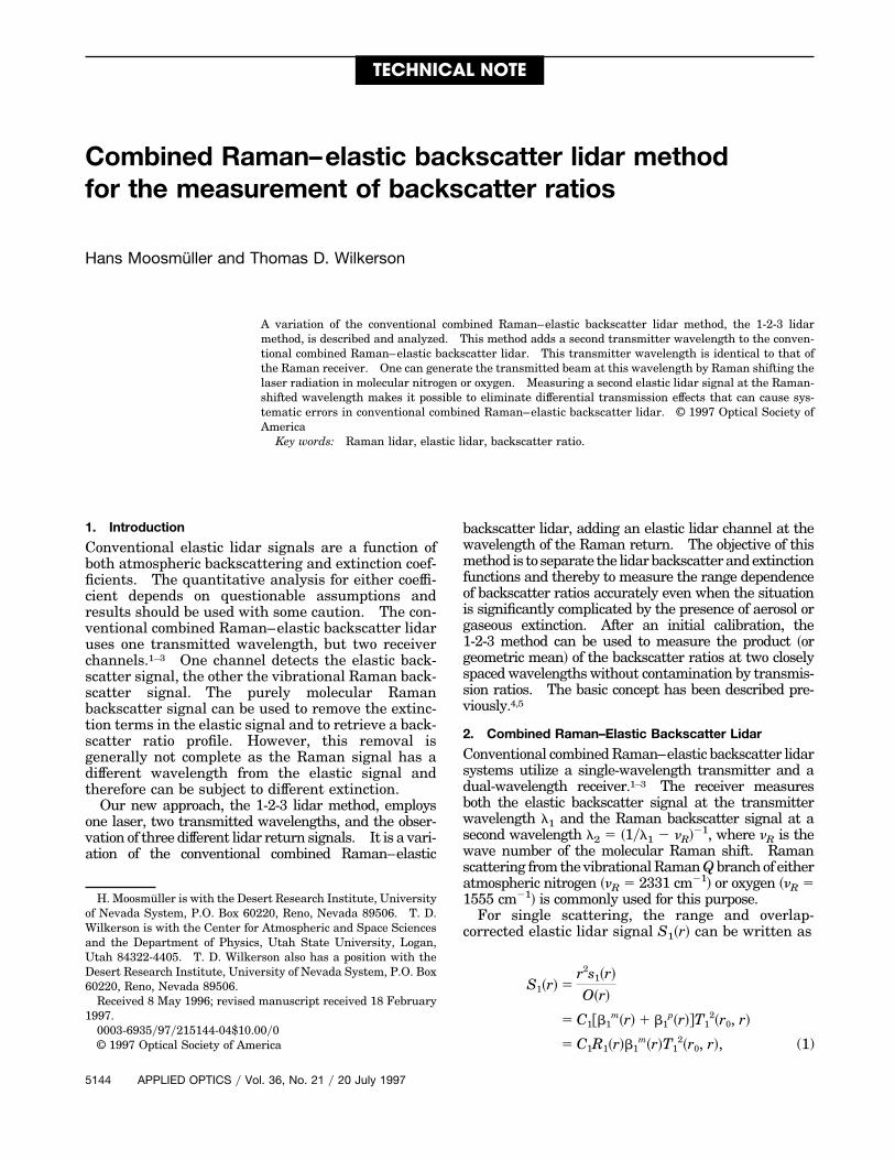
The transmission of laser pulses alternates betweenl1 and l2. When a pulse at l1 is transmitted, boththe elastic backscattering and the frequency-shiftedRaman backscattering from atmospheric N2 are ob-served at l1 and l2, respectively. For the inter-leaved laser pulses at l2, only the elasticbackscattering at l2 is observed. A schematic dia-gram of the 1-2-3 lidar system is shown in Fig. 1.
The second elastic backscatter signal at l2 can bewritten equivalent to Eq. ~1! as
S2~r! 5r2s2~r!
O~r!
5 C2@b2m~r! 1 b2
p~r!#T22~r0, r!
5 C2R2~r!b2m~r!T2
2~r0, r!, (6)
and, together with the Raman backscattering signalS1,2~r!, it yields the backscatter ratio R2~r! at l2:
R2~r! 5C1,2b1,2
m~r!T1~r0, rref!
C2b2m~r!T2~r0, rref!
T1~rref, r!
T2~rref, r!
S2~r!
S1,2~r!. (7)
Equation ~7! is equivalent to Eq. ~5!, however, withinverse dependence on the transmission ratios.Therefore, the product of the two backscatter ratiosR1~r! and R2~r! yields a local measurement of back-scatter properties uncontaminated by range-integrated transmissions. The geometric mean
Fig. 1. Schematic diagram of the 1-2-3 lidar system.
20 July 1997 y Vol. 36, No. 21 y APPLIED OPTICS 5145
R1,2~r! of the backscatter ratios R1~r! and R2~r! can bewritten as
R1,2~r! 5 @R1~r!R2~r!#1y2
5@C1,2b1,2
m~r!
C1C2b1m~r!b2
m~r!
S1~r!S2~r!
@S1,2~r!#2
5 CS1~r!S2~r!
@S1,2~r!#2 , (8)
where C is a constant. This simple analytical resultis the basis of the 1-2-3 lidar method and can beinterpreted as follows. The elastic backscatter lidarsignals S1 and S2 each include a two-way transmis-sion term at their individual wavelength, T1
2 andT2
2, respectively. The Raman signal S1,2, on theother hand, includes a transmission term T1 for thetransmission of laser light at wavelength l1 to ranger and a transmission term T2 for the return trans-mission of scattered light at wavelength l2. Di-viding the product of the elastic signals S1 and S2 bythe square of the inelastic Raman signal S1,2
2 there-fore completely removes the transmission terms and,in addition, normalizes the elastic scattering with themolecular Raman scattering, yielding a backscatterratio R1,2. This backscatter ratio R1,2 is the geomet-ric mean of the backscatter ratios at the closelyspaced wavelengths l1 and l2 and is a useful param-eter to describe the atmospheric turbidity.
The advantages of the 1-2-3 lidar method comparedwith the conventional combined Raman–elastic back-scatter lidar can be deduced directly from Eq. ~8!. Thecalibration factor C is a true constant, independent ofatmospheric conditions. Therefore, a one-time cali-bration with particle-free air at some reference rangeis sufficient. This calibration can be used for all at-mospheric conditions as long as the system constantsC1, C2, and C1,2 remain constant. The ease of cali-bration is especially relevant for tropospheric mea-surements for which the measurement range oftendoes not include an aerosol-free region. In addition,the measured backscatter ratio R1,2~r! is a truly localproperty, not influenced by the transmission ratioT1yT2 between the reference and measurement range.This can be an important advantage, especially forlidar systems that operate in the ultraviolet wave-length region where the wavelength-dependent ab-sorption of ozone contributes to the transmission ratio.
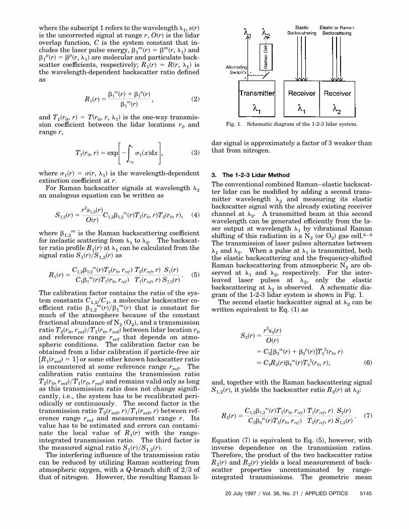
A specific example for a solar-blind lidar systemutilizing the fourth harmonic of a Nd:YAG laser asthe transmitted wavelength ~l1 5 266 nm! and Ra-man shifting in nitrogen to generate the second wave-length ~l2 5 284 nm! is illustrated in Figs. 2~a!–2~c!.A simple model profile is used with an aerosol-freeregion ~R1 5 1! at and around the reference range rrefused for the calibration of conventional combined li-dar, followed by a homogeneous aerosol layer ~R1 5 3for rref 1 600 m # r # rref 1 1200 m! and relativelyclear air beyond this layer ~R1 5 1.2 for r $ rref 11200 m!. The model backscatter ratio R2 is calcu-lated from R1 under the assumption of constant mo-
5146 APPLIED OPTICS y Vol. 36, No. 21 y 20 July 1997
lecular density, corresponding to a near-horizontalpath, and of a constant particulate backscatteringphase function of 0.025 sr21. Each part of Fig. 2
Fig. 2. Model atmospheric backscatter ratio profiles and profilesretrieved by conventional combined Raman–elastic lidar and by the1-2-3 method for a solar-blind lidar utilizing a quadrupled Nd:YAGlaser at 266 nm and Raman shifting in nitrogen. ~a! The differen-tial extinction between l1 5 266 nm and l2 5 284 nm is due toRayleigh extinction. ~b! The differential extinction between l1 5266 nm and l2 5 284 nm is due to Rayleigh and aerosol ~u 5 1!extinction. The retrieved R1 profile is corrected for differential Ray-leigh extinction. ~c! The differential extinction between l1 5 266nm and l2 5 284 nm is due to Rayleigh, aerosol ~u 5 1!, and ozone~10 ppb! extinction. The retrieved R1 profile is corrected for differ-ential Rayleigh extinction.
shows model profiles of R1 and R2, the R1 profileretrieved by conventional combined lidar, and theR1,2 profile retrieved by the 1-2-3 lidar method. InFig. 2~a!, the transmission ratio is due solely to Ray-leigh extinction. However, the retrieved R1 profilecould be corrected for the differential Rayleigh extinc-tion as its magnitude is well known. In Fig. 2~b!differential aerosol extinction corresponding to thecommonly used Ångstrom coefficient of u 5 1 @s2
pys1p
5 ~l1yl2!u for aerosol extinction# is added. The re-trieved R1 profile in Fig. 2~b! is corrected for differ-ential Rayleigh extinction. Correction of theretrieved R1 profile for aerosol extinction is more dif-ficult as the Ångstrom coefficient u is generally notknown. If an estimate u is used to correct the re-trieved R1 profile, Fig. 2~b! can be interpreted to showthe error of the corrected R1 profile that is due to anerror in estimating u of u 2 u 5 1. Figure 2~c! showsthe added effect of 10 ppb of ozone. The retrieved R1profile is again corrected for differential Rayleigh ex-tinction. The effect that is due to 10 ppb of ozonecorresponds to common errors in the measurement ofa tropospheric ozone profile. If such measurementsare not available the resulting distortion could bemuch worse. In summary, although the R1 profilesretrieved by the conventional combined lidar are dis-torted due to uncorrected differential absorption ef-fects, the R1,2 profiles retrieved by the 1-2-3 lidarmethod are completely unaffected.
4. Conclusions
The 1-2-3 lidar method is a straightforward conceptthat can be used to measure backscatter ratios un-contaminated by differential extinction. Especiallyin spectral regions affected by differential gaseousabsorption, the 1-2-3 lidar method can yield signifi-cantly more accurate backscatter ratio profiles than
the conventional combined Raman–elastic lidar.However, this theoretical advantage will have to beevaluated experimentally in the future.
This research has been supported in part by anInstitutional Project Assignment of the Desert Re-search Institute and by the CEDAR ~Coupling, Ener-getics, and Dynamics of Atmospheric Regions!Program of the National Science Foundation.
References1. J. Cooney, J. Orr, and C. Tomasetti, “Measurements separating
the gaseous and aerosol components of laser atmospheric back-scatter,” Nature ~London! 224, 1098–1099 ~1969!.
2. S. H. Melfi, “Remote measurements of the atmosphere usingRaman scattering,” Appl. Opt. 11, 1605–1610 ~1972!.
3. A. Ansmann, M. Riebesell, U. Wandinger, C. Weitkamp, E.Voss, W. Lahmann, and W. Michaelis, “Combined Ramanelastic-backscatter lidar for vertical profiling of moisture, aero-sol extinction, backscatter, and lidar ratio,” Appl. Phys. B 55,18–28 ~1992!.
4. V. M. Mitchenkov and A. V. Soludukhin, “Three wavelengthlidar with a single laser source for probing the optical tropo-spheric parameters,” in Proceedings of 15th International LaserRadar Conference ~Institute of Atmospheric Optics, Tomsk,1990!, pp. 345–346.
5. T. D. Wilkerson and H. Moosmuller, “A new lidar method uti-lizing elastic and Raman scattering for the measurement ofbackscattering and extinction profiles,” in Tunable Diode LaserSpectroscopy, Lidar, and DIAL Techniques, H. I. Schiff, A. Fried,and D. K. Killinger, eds., Proc. SPIE 2112, 177–186 ~1994!.
6. Z. Chu, U. N. Singh, and T. D. Wilkerson, “A self-seeded SRSsystem for the generation of 1.54 mm eye-safe radiation,” Opt.Commun. 75, 173–178 ~1990!.
7. S. E. Bisson, “Parametric study of an excimer-pumped, nitrogenRaman shifter for lidar applications,” Appl. Opt. 34, 3406–3412~1995!.
8. B. Zhang, W. R. Lempert, R. B. Miles, and G. Diskin, “Efficientvibrational Raman conversion in O2 and N2 cells by use ofsuperfluorescence seeding,” Opt. Lett. 18, 1132–1134 ~1993!.
20 July 1997 y Vol. 36, No. 21 y APPLIED OPTICS 5147