atmospheric corrections determined using raman/backscatter lidar measurements valentin mitev
DESCRIPTION
Atmospheric corrections determined using Raman/backscatter lidar measurements Valentin Mitev Observatory of Neuchâtel Rue de l’Observatoire 58, CH2000 Neuchâtel Switzerland Tel.: +41–32–889 8813 E-mail: [email protected]. Content: • Measurement requirements - PowerPoint PPT PresentationTRANSCRIPT
HEAPnet meeting, 19-20 February 2007, Amsterdam
Atmospheric corrections determined using Raman/backscatter lidar measurements 1
LIDAR
Atmospheric corrections determined using Raman/backscatter lidar
measurements
Valentin Mitev
Observatory of NeuchâtelRue de l’Observatoire 58, CH2000 NeuchâtelSwitzerlandTel.: +41–32–889 8813E-mail: [email protected]
HEAPnet meeting, 19-20 February 2007, Amsterdam
Atmospheric corrections determined using Raman/backscatter lidar measurements 2
LIDAR
Content:
• Measurement requirements• Concept for the Lidar set-up• Extinction derivation, vibrational Raman• Numerical performance simulations
for Extinction derivation, Raman lidar• Extinction derivation, elastic backscatter • Temperature derivation, pure Rotational Raman• Conclusion
• Annex: Compact backscatter lidar in field measurements
HEAPnet meeting, 19-20 February 2007, Amsterdam
Atmospheric corrections determined using Raman/backscatter lidar measurements 3
LIDAR
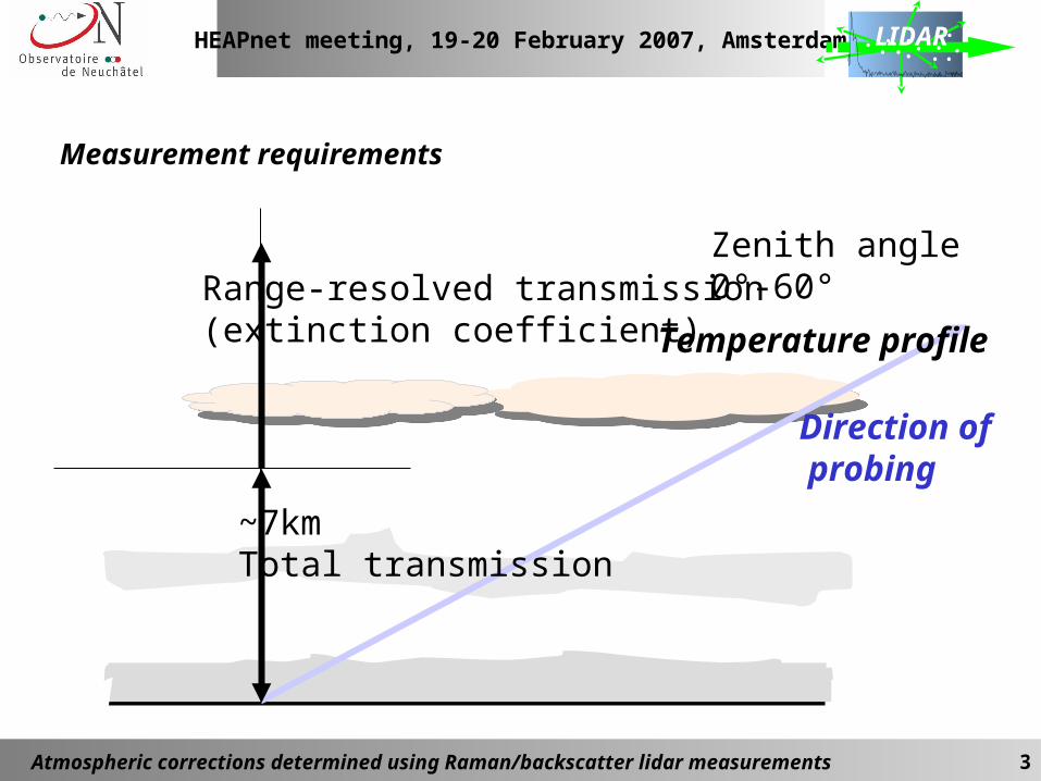
~7kmTotal transmission
Range-resolved transmission (extinction coefficient)
Zenith angle0°-60°
Measurement requirements
Direction of probing
Temperature profile
HEAPnet meeting, 19-20 February 2007, Amsterdam
Atmospheric corrections determined using Raman/backscatter lidar measurements 4
LIDAR
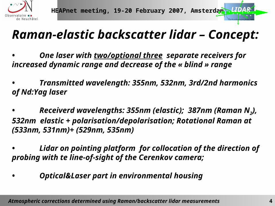
Raman-elastic backscatter lidar – Concept:
• One laser with two/optional three separate receivers for increased dynamic range and decrease of the « blind » range
• Transmitted wavelength: 355nm, 532nm, 3rd/2nd harmonics of Nd:Yag laser
• Receiverd wavelengths: 355nm (elastic); 387nm (Raman N2), 532nm elastic + polarisation/depolarisation; Rotational Raman at (533nm, 531nm)+ (529nm, 535nm)
• Lidar on pointing platform for collocation of the direction of probing with te line-of-sight of the Cerenkov camera;
• Optical&Laser part in environmental housing
HEAPnet meeting, 19-20 February 2007, Amsterdam
Atmospheric corrections determined using Raman/backscatter lidar measurements 5
LIDAR
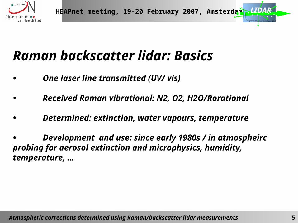
Raman backscatter lidar: Basics
• One laser line transmitted (UV/ vis)
• Received Raman vibrational: N2, O2, H2O/Rorational
• Determined: extinction, water vapours, temperature
• Development and use: since early 1980s / in atmospheirc probing for aerosol extinction and microphysics, humidity, temperature, …
HEAPnet meeting, 19-20 February 2007, Amsterdam
Atmospheric corrections determined using Raman/backscatter lidar measurements 6
LIDAR
HEAPnet meeting, 19-20 February 2007, Amsterdam
Atmospheric corrections determined using Raman/backscatter lidar measurements 7
LIDAR
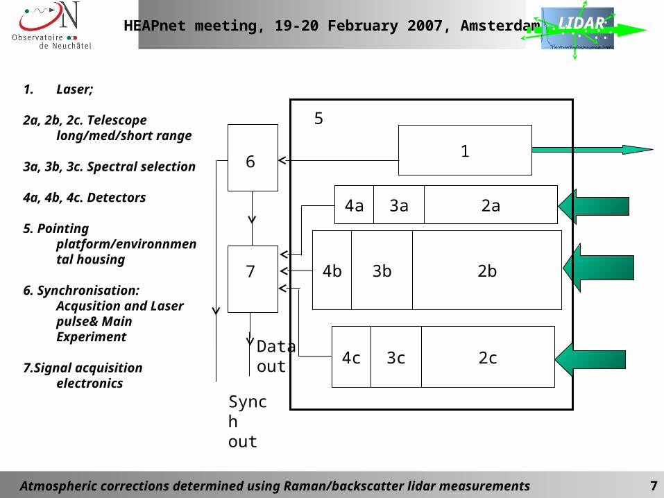
1. Laser;
2a, 2b, 2c. Telescope long/med/short range
3a, 3b, 3c. Spectral selection
4a, 4b, 4c. Detectors
5. Pointing platform/environnmental housing
6. Synchronisation: Acqusition and Laser pulse& Main Experiment
7.Signal acquisition electronics
Synch out
1
5
2a3a4a
2b3b4b
6
7
Data out 2c3c4c
HEAPnet meeting, 19-20 February 2007, Amsterdam
Atmospheric corrections determined using Raman/backscatter lidar measurements 8
LIDAR
532nm, 355nm
532nm
387nm
532nm-s
532nm -p
355nmRR1…RR4
532nm (e)
355nm (e)
356/8nm (2*RR-S)352/4nm (2*RR-aS)
aS1/ aS2/ 355nm/ S1/ S2
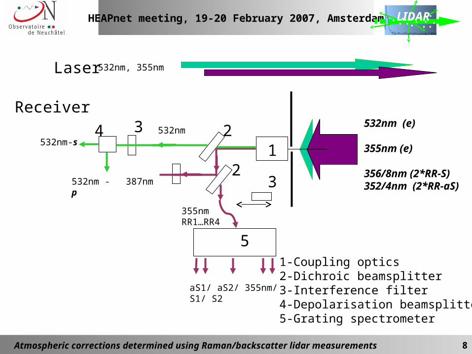
Laser
Receiver
123
3
4
51-Coupling optics2-Dichroic beamsplitter3-Interference filter4-Depolarisation beamsplitter5-Grating spectrometer
2
HEAPnet meeting, 19-20 February 2007, Amsterdam
Atmospheric corrections determined using Raman/backscatter lidar measurements 9
LIDAR
r
0RR2RLR 'dr)'r()'r(exp)r(
2
c
r
A)r(OKE)r(E
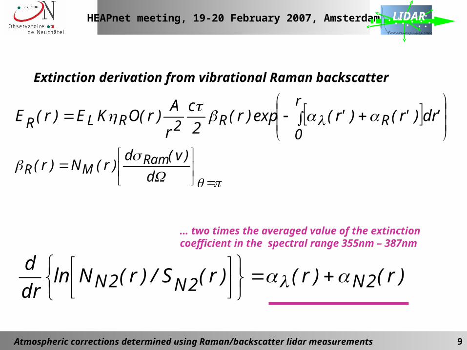
Extinction derivation from vibrational Raman backscatter
d
)v(d)r(N)r( Ram
MR
)r()r()r(S/)r(Nlndr
d2N2N2N
… two times the averaged value of the extinction coefficient in the spectral range 355nm – 387nm
HEAPnet meeting, 19-20 February 2007, Amsterdam
Atmospheric corrections determined using Raman/backscatter lidar measurements 10
LIDAR
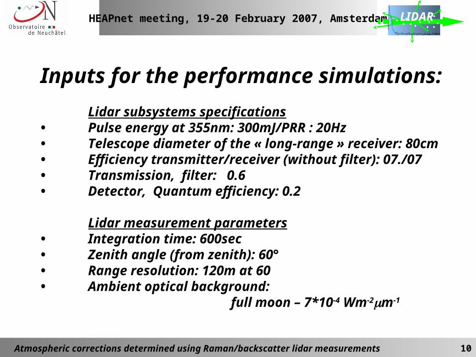
Inputs for the performance simulations:
Lidar subsystems specifications• Pulse energy at 355nm: 300mJ/PRR : 20Hz• Telescope diameter of the « long-range » receiver: 80cm • Efficiency transmitter/receiver (without filter): 07./07• Transmission, filter: 0.6• Detector, Quantum efficiency: 0.2
Lidar measurement parameters• Integration time: 600sec• Zenith angle (from zenith): 60°• Range resolution: 120m at 60• Ambient optical background:
full moon – 7*10-4 Wm-2m-1
HEAPnet meeting, 19-20 February 2007, Amsterdam
Atmospheric corrections determined using Raman/backscatter lidar measurements 11
LIDAR
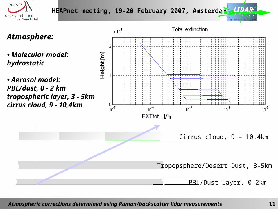
Atmosphere:
• Molecular model: hydrostatic
• Aerosol model: PBL/dust, 0 - 2 kmtropospheric layer, 3 - 5kmcirrus cloud, 9 - 10,4km
PBL/Dust layer, 0-2km
Tropopsphere/Desert Dust, 3-5km
Cirrus cloud, 9 – 10.4km
HEAPnet meeting, 19-20 February 2007, Amsterdam
Atmospheric corrections determined using Raman/backscatter lidar measurements 12
LIDAR
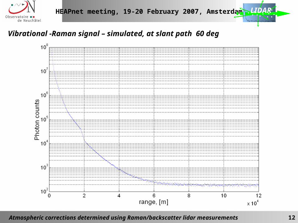
Vibrational -Raman signal – simulated, at slant path 60 deg
HEAPnet meeting, 19-20 February 2007, Amsterdam
Atmospheric corrections determined using Raman/backscatter lidar measurements 13
LIDAR
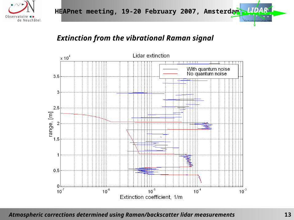
Extinction from the vibrational Raman signal
HEAPnet meeting, 19-20 February 2007, Amsterdam
Atmospheric corrections determined using Raman/backscatter lidar measurements 14
LIDAR
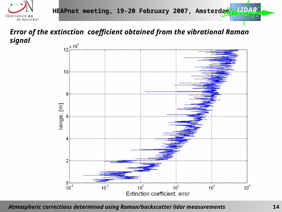
Error of the extinction coefficient obtained from the vibrational Raman signal
HEAPnet meeting, 19-20 February 2007, Amsterdam
Atmospheric corrections determined using Raman/backscatter lidar measurements 15
LIDAR
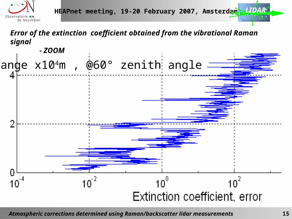
Error of the extinction coefficient obtained from the vibrational Raman signal- ZOOM
Range x104m , @60° zenith angle
HEAPnet meeting, 19-20 February 2007, Amsterdam
Atmospheric corrections determined using Raman/backscatter lidar measurements 16
LIDAR
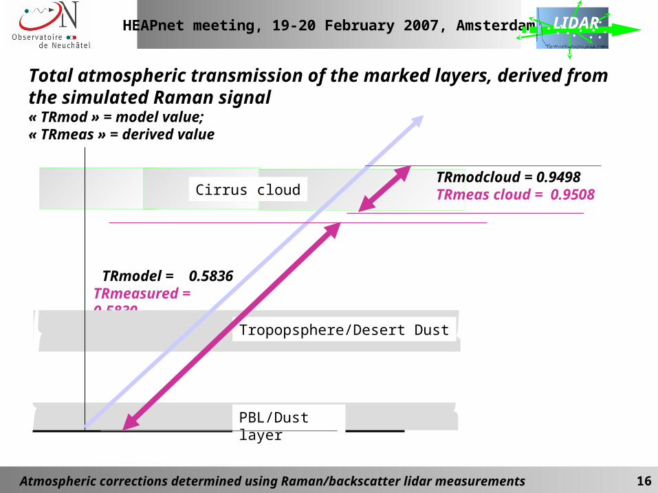
Total atmospheric transmission of the marked layers, derived from the simulated Raman signal« TRmod » = model value; « TRmeas » = derived value
TRmodel = 0.5836TRmeasured = 0.5830
PBL/Dust layer
Tropopsphere/Desert Dust
Cirrus cloudTRmodcloud = 0.9498TRmeas cloud = 0.9508
HEAPnet meeting, 19-20 February 2007, Amsterdam
Atmospheric corrections determined using Raman/backscatter lidar measurements 17
LIDAR
Concept for derivation of the extinction coefficient inside aerosol layer using elastic backscatter
Assumptions:- The layer contains the same type of aerosol (e.g.,subvisible cirrus cloud)- Aerisol-free atmosphere above the cloud- Total layer (cloud) transmision is determined from the Raman signal
HEAPnet meeting, 19-20 February 2007, Amsterdam
Atmospheric corrections determined using Raman/backscatter lidar measurements 18
LIDAR
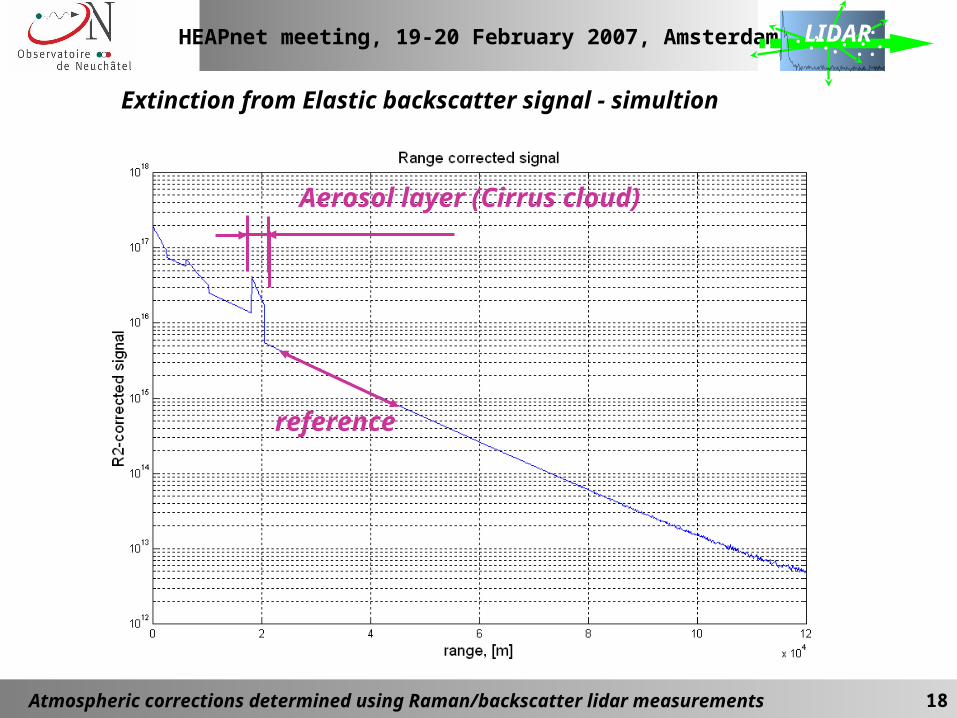
Extinction from Elastic backscatter signal - simultion
reference
Aerosol layer (Cirrus cloud)
HEAPnet meeting, 19-20 February 2007, Amsterdam
Atmospheric corrections determined using Raman/backscatter lidar measurements 19
LIDAR
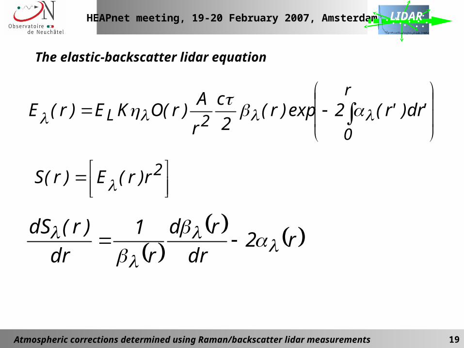
The elastic-backscatter lidar equation
r
02L 'dr)'r(2exp)r(
2
c
r
A)r(OKE)r(E
2r)r(E)r(S
r2
dr
rd
r
1
dr
)r(dS
HEAPnet meeting, 19-20 February 2007, Amsterdam
Atmospheric corrections determined using Raman/backscatter lidar measurements 20
LIDAR
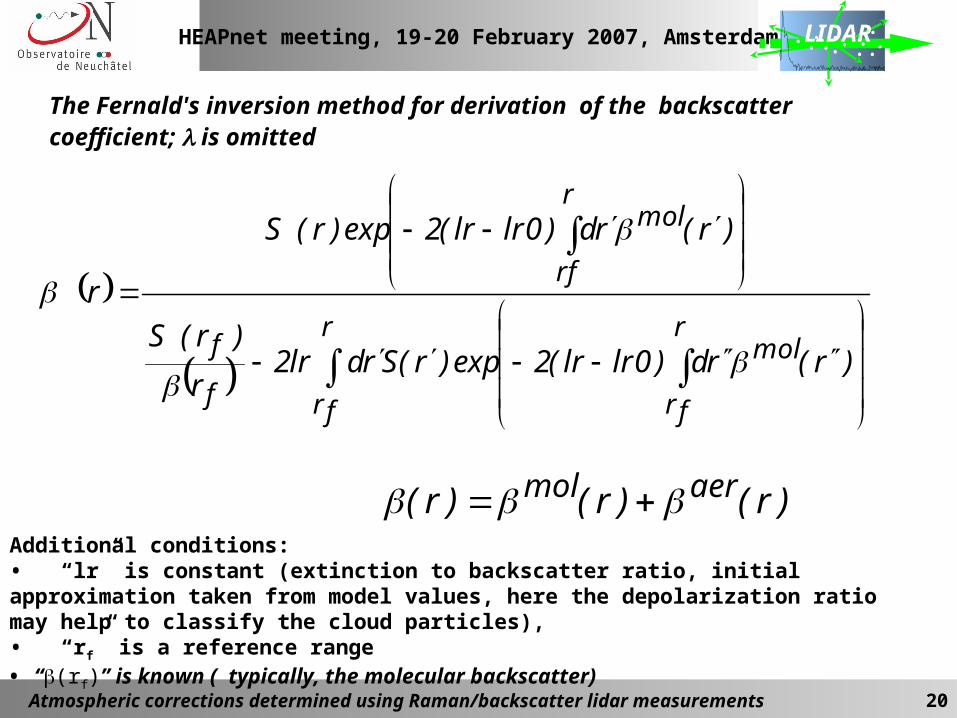
The Fernald's inversion method for derivation of the backscatter coefficient; is omitted
r
fr
r
fr
mol
f
f
r
rf
mol
)r(rd)0lrlr(2exp)r(Srdlr2r
)r(S
)r(rd)0lrlr(2exp)r(S
r
Additional conditions: • “lr” is constant (extinction to backscatter ratio, initial approximation taken from model values, here the depolarization ratio may help to classify the cloud particles), • “rf” is a reference range• “(rf)” is known ( typically, the molecular backscatter)
)r()r()r( aermol
HEAPnet meeting, 19-20 February 2007, Amsterdam
Atmospheric corrections determined using Raman/backscatter lidar measurements 21
LIDAR
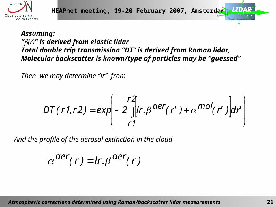
Assuming: “(r)” is derived from elastic lidar Total double trip transmission “DT” is derived from Raman lidar, Molecular backscatter is known/type of particles may be “guessed”
Then we may determine “lr” from
And the profile of the aerosol extinction in the cloud
2r
1r
molaer 'dr)'r()'r(.lr2exp)2r,1r(DT
)r(.lr)r( aeraer
HEAPnet meeting, 19-20 February 2007, Amsterdam
Atmospheric corrections determined using Raman/backscatter lidar measurements 22
LIDAR
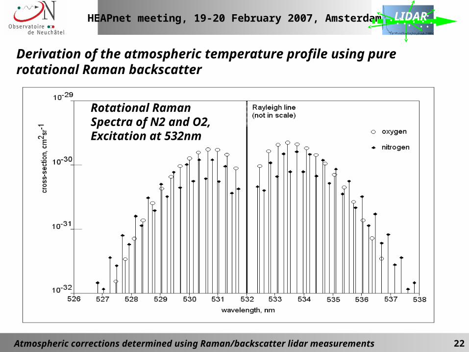
Derivation of the atmospheric temperature profile using pure rotational Raman backscatter
Rotational Raman Spectra of N2 and O2,Excitation at 532nm
HEAPnet meeting, 19-20 February 2007, Amsterdam
Atmospheric corrections determined using Raman/backscatter lidar measurements 23
LIDAR
Temperature derivative in Rotational Raman spectraof N2 (red) and O2 (black)
-1
-0,5
0
0,5
1
1,5
2
2,5
3
3,5
525 526 527 528 529 530 531 532 533 534 535 536 537 538 539 540
wavelength, nm
deriv
ativ
e, re
lativ
e un
its
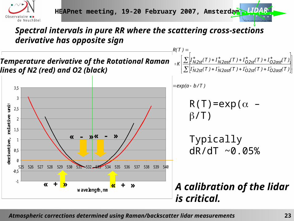
Spectral intervals in pure RR where the scattering cross-sections derivative has opposite sign
)T/baexp(
)T(I)T(I)T(I)T(I
)T(I)T(I)T(I)T(IK
)T(R
ast2Ost2Oast2Nst2N
ast2Ost2Oast2Nst2N
A calibration of the lidar is critical.
« + »
« - »« - »
Temperature derivative of the Rotational Raman lines of N2 (red) and O2 (black)
« + »
R(T)=exp( – /T)
Typically dR/dT ~0.05%
HEAPnet meeting, 19-20 February 2007, Amsterdam
Atmospheric corrections determined using Raman/backscatter lidar measurements 24
LIDAR
HEAPnet meeting, 19-20 February 2007, Amsterdam
Atmospheric corrections determined using Raman/backscatter lidar measurements 25
LIDAR
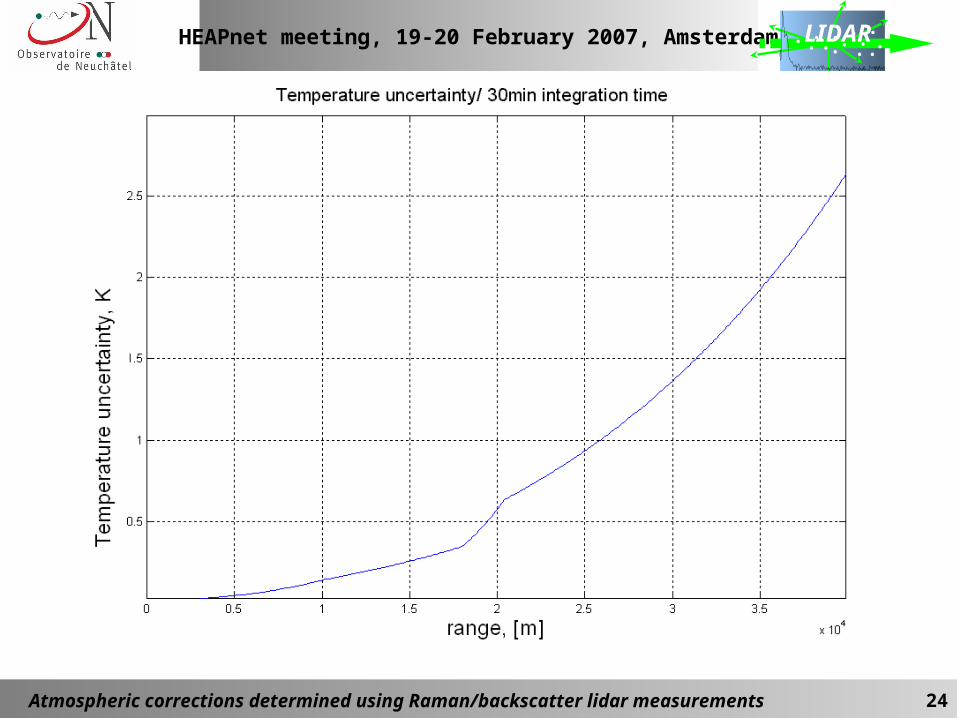
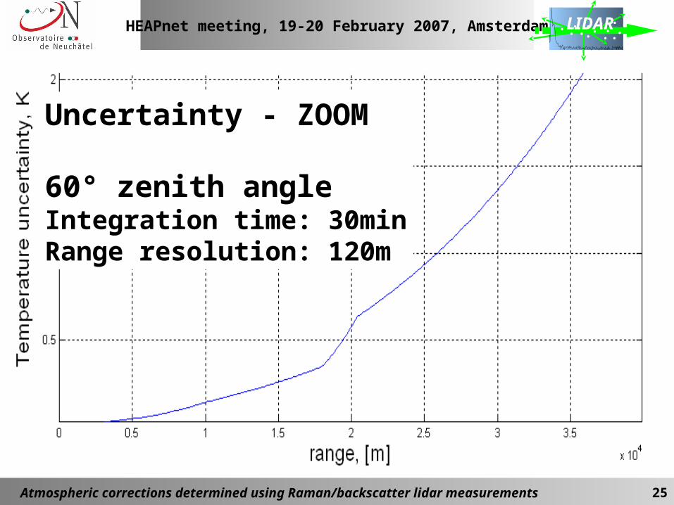
Uncertainty - ZOOM
60° zenith angleIntegration time: 30minRange resolution: 120m
HEAPnet meeting, 19-20 February 2007, Amsterdam
Atmospheric corrections determined using Raman/backscatter lidar measurements 26
LIDAR
Summary:A Raman-backscatter Lidar for CTA-site is a technically feasible solution for the requirements in CTA:
• Advantages: « Real time » and « Real direction » coinciding with the pointing direction the Cherenkov Telescope(s) • The necessary lidar methods and algorithms are developed, adaptation to the tasks will be possible ;• Realistic subsystem specifications, compatible with the commercially available hardware;• Additional /Optional lidar tasks: laser backscatter for calibration of the Cherenkov telescope;
Remark: This presentation is not with system optimisation. The final specifications may be different from the specifications used for numerical simulations
HEAPnet meeting, 19-20 February 2007, Amsterdam
Atmospheric corrections determined using Raman/backscatter lidar measurements 27
LIDAR
Next step for the Raman lidar - a design study with the following objectives:
• Detailed numerical simulations of the various detection modes with respect to the finalised detection requirements
• Concept design and optimisation;
• Algorithm developments;
• Optional 1: Participation in atmospheric characterisation at the potential CTA sites;• Optional 2: Raman lidar bread-board/ lower aperture and power
HEAPnet meeting, 19-20 February 2007, Amsterdam
Atmospheric corrections determined using Raman/backscatter lidar measurements 28
LIDAR
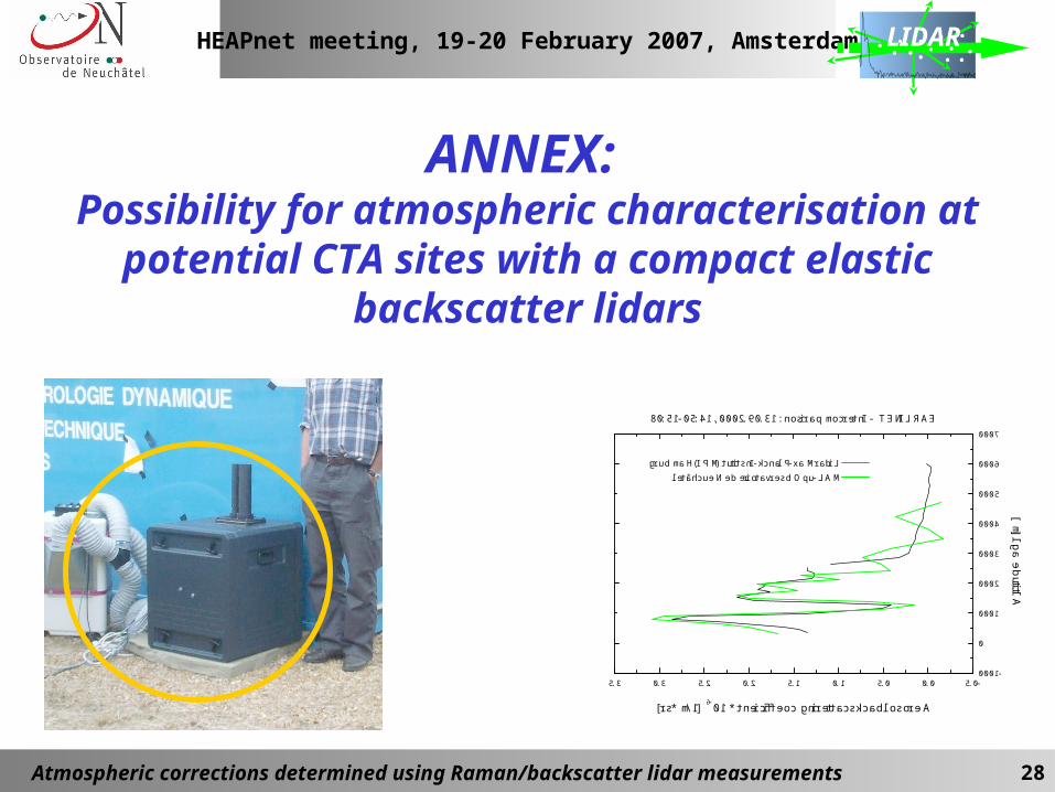
ANNEX: Possibility for atmospheric characterisation at
potential CTA sites with a compact elastic backscatter lidars
HEAPnet meeting, 19-20 February 2007, Amsterdam
Atmospheric corrections determined using Raman/backscatter lidar measurements 29
LIDAR
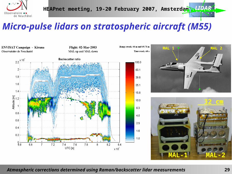
Micro-pulse lidars on stratospheric aircraft (M55)
MAL 1 MAL 2
MAL-1 MAL-2
32 cm
HEAPnet meeting, 19-20 February 2007, Amsterdam
Atmospheric corrections determined using Raman/backscatter lidar measurements 30
LIDAR
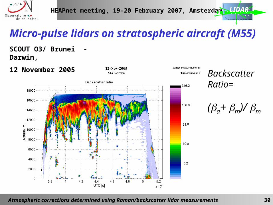
Micro-pulse lidars on stratospheric aircraft (M55)SCOUT O3/ Brunei - Darwin,
12 November 2005 Backscatter Ratio=
(a+ m)/ m
HEAPnet meeting, 19-20 February 2007, Amsterdam
Atmospheric corrections determined using Raman/backscatter lidar measurements 31
LIDAR
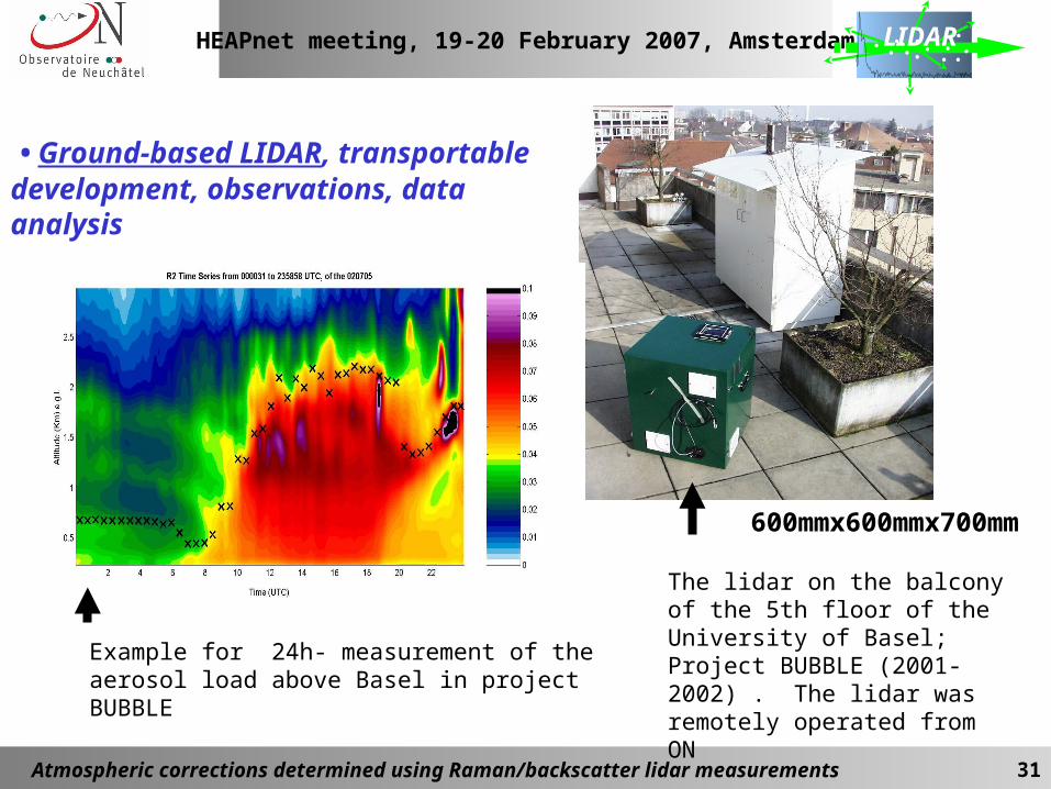
• Ground-based LIDAR, transportable development, observations, data analysis
The lidar on the balcony of the 5th floor of the University of Basel; Project BUBBLE (2001-2002) . The lidar was remotely operated from ON
Example for 24h- measurement of the aerosol load above Basel in project BUBBLE
600mmx600mmx700mm
HEAPnet meeting, 19-20 February 2007, Amsterdam
Atmospheric corrections determined using Raman/backscatter lidar measurements 32
LIDAR
• Ground-based three-wavelength elastic Raman LIDAR, in Observatory of Neuchatel
Operational, Presently under refurbishment
Concerning the CTA-activity:
• Not transportable
• May be a base for the Raman lidar bread-board/test bench wrt the CTA requirements
• Possibility to be deployed on site (with limitations for steering, schedule …)
HEAPnet meeting, 19-20 February 2007, Amsterdam
Atmospheric corrections determined using Raman/backscatter lidar measurements 33
LIDAR
Summary for the “compact lidar” capabilities:
- Possibility for qualitative characterisation of the aerosol vertical/slant path profile: Backscatter coefficient profile (~30% uncertainty, systematic), altitude of layers,
-Convenient transportation and implementation on the field
- Limitations: The qualitative evaluation is not adequate to the requirements in CTI, i.e., NOT a replacement for the Raman lidar)
HEAPnet meeting, 19-20 February 2007, Amsterdam
Atmospheric corrections determined using Raman/backscatter lidar measurements 34
LIDAR
Thank you!
Valentin Mitev([email protected])
Observatory of NeuchâtelRue de l’Observatoire 58, CH2000 NeuchâtelSwitzerland