colloid mobilization and transport during capillary fringe fluctuations
TRANSCRIPT
Colloid Mobilization and Transport during Capillary FringeFluctuationsSurachet Aramrak,†,‡,∥ Markus Flury,*,‡ James B. Harsh,† and Richard L. Zollars§
†Department of Crop and Soil Sciences, §The Gene and Linda Voiland School of Chemical Engineering and Bioengineering,Washington State University, Pullman, Washington 99164, United States‡Department of Crop and Soil Sciences, Washington State University, Puyallup, Washington 98371, United States
*S Supporting Information
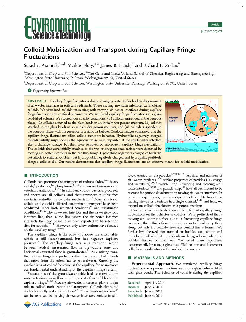
ABSTRACT: Capillary fringe fluctuations due to changing water tables lead to displacementof air−water interfaces in soils and sediments. These moving air−water interfaces can mobilizecolloids. We visualized colloids interacting with moving air−water interfaces during capillaryfringe fluctuations by confocal microscopy. We simulated capillary fringe fluctuations in a glass-bead-filled column. We studied four specific conditions: (1) colloids suspended in the aqueousphase, (2) colloids attached to the glass beads in an initially wet porous medium, (3) colloidsattached to the glass beads in an initially dry porous medium, and (4) colloids suspended inthe aqueous phase with the presence of a static air bubble. Confocal images confirmed that thecapillary fringe fluctuations affect colloid transport behavior. Hydrophilic negatively chargedcolloids initially suspended in the aqueous phase were deposited at the solid−water interfaceafter a drainage passage, but then were removed by subsequent capillary fringe fluctuations.The colloids that were initially attached to the wet or dry glass bead surface were detached bymoving air−water interfaces in the capillary fringe. Hydrophilic negatively charged colloids didnot attach to static air-bubbles, but hydrophobic negatively charged and hydrophilic positivelycharged colloids did. Our results demonstrate that capillary fringe fluctuations are an effective means for colloid mobilization.
■ INTRODUCTION
Colloids can promote the transport of radionuclides,1−4 heavymetals,5 pesticides,6,7 phosphorus,8−10 and animal hormones andveterinary antibiotics.11,12 In addition, viruses, bacteria, protozoa,and spores are all colloids, and their transport in subsurfacemedia is controlled by colloidal mechanisms.13 Many studies ofcolloid and colloid-facilitated contaminant transport have beenconducted under both saturated conditions14 and unsaturatedconditions.15,16 The air−water interface and the air−water−solidinterface line, that is, the line where the air−water interfaceintersects the solid phase, have been reported to be retentionsites for colloids.17−19 However, only a few authors have focusedon the capillary fringe.20−23
The capillary fringe is the zone just above the water table,which is still water-saturated, but has negative capillarypressure.24 The capillary fringe acts as a transition regionbetween vertical unsaturated flow in the vadose zone andhorizontal saturated flow in groundwater.25 As a mixing zone,the capillary fringe is expected to affect the transport of colloidsthat move from the subsurface to groundwater. Knowing themechanisms of colloid behavior in the capillary fringe increasesour fundamental understanding of the capillary fringe system.Fluctuations of the groundwater table lead to moving air−
water interfaces as well as to entrapment of air bubbles in thecapillary fringe.25,26 Moving air−water interfaces play a majorrole in colloid mobilization and transport. Colloids depositedon both initially wet solid surfaces27−33 and air-dried surfaces34
can be removed by moving air−water interfaces. Surface tension
forces exerted on the particles,27,28,35−39 velocities and numbers ofair−water interfaces,29,33 surface properties of particles (i.e., chargeand wettability),30,34 particle size,31 advancing and receding air−water interfaces,32,33 and particle shape40 have all been found to berelevant for particle detachment by moving air−water interfaces. Inprevious experiments, we investigated colloid detachment bymoving air−water interfaces in a single channel,33,40 and here, weexpand on colloid detachment in a porous medium.Our objective was to determine the effect of capillary fringe
fluctuations on the behavior of colloids. We hypothesized that amoving air−water interface due to a fluctuating capillary fringecan scour the colloids from the medium surface and carry themalong, but only if a colloid−air−water contact line is formed. Wefurther hypothesized that trapped air bubbles can capture andimmobilize colloids, but the colloids are being released when thebubbles dissolve or flush out. We tested these hypothesesexperimentally by using a glass bead-filled column and fluorescentcolloids in combination with confocal microscopy.
■ MATERIALS AND METHODSExperimental Approach. We simulated capillary fringe
fluctuations in a porous medium made of a glass column filledwith glass beads. The behavior of colloids during the capillary
Received: April 11, 2014Revised: June 3, 2014Accepted: June 4, 2014Published: June 4, 2014
Article
pubs.acs.org/est
© 2014 American Chemical Society 7272 dx.doi.org/10.1021/es501797y | Environ. Sci. Technol. 2014, 48, 7272−7279
fringe fluctuations were visualized by confocal microscopy. Tovisualize the different phases, we used fluorescent colloids and afluorescent aqueous solution. This allowed us to distinguish thecolloids; the water and air phases, including the air−waterinterfaces; and the glass beads in real time.We selected four scenarios for the capillary fringe experi-
ments (Figure S2, Supporting Information). The first threescenarios were situations of colloids interacting with a movingair−water interface. These are (a) colloids suspended in theaqueous phase while the aqueous phase imbibes and drainsthe porous medium to simulate capillary fringe fluctuations;(b) colloids initially attached to the glass beads in a wet porousmedium; and (c) colloids initially attached to the glass beads ina dry porous medium. The last scenario (d) mimics a situationwhen moving colloids interact with a static air−water interface(i.e., a trapped air bubble).Capillary Fringe System. We used a small-diameter
(i.d. 1.5 mm) glass column of 7.5 cm length (see SupportingInformation and Figure S1 for more details). We prepared andcleaned the column as described previously,33,40 and filled thecolumn with glass beads. The glass beads had a diameter of400−600 μm (EW-36270-51, Cole-Parmer Instrument Co., IL).These glass beads were soaked overnight in 10% HCl, rinsedwith DI water, and air-dried at room temperature before beingfilled into the channel. We verified the size uniformity of the glassbeads by scanning electron microscopy (FEI Quanta 200F, FEICo., Hillsboro, OR). The porosity of the packed column wasdetermined by measuring the weight difference between a drycolumn and a water-saturated column. We then used this weightdifference to calculate the saturated volumetric water content,
which is equivalent to the porosity of the packed column. Theporosity of our system was 0.55 cm3/cm3. This high porosity wasdue to boundary effects of the glass channel, preventing a closepacking along the channel walls. We focused our confocal viewduring our experiments into the interior of the channel, andtherefore, this boundary effect is not expected to be significant.Both ends of the column were connected to Tygon tubes,
and one of the tubes was connected to a withdrawing/infusingsyringe pump (KDS 210, KD Scientific, Holliston, MA) so thatwe could introduce and control capillary fringe fluctuations.The other end of the column was left open to an outflowcontainer to allow free passage of air in and out of the channel.The column was then placed horizontally on the platform of alaser scanning confocal microscope (Axiovert 200 M equippedwith LSM 510 META, Carl Zeiss Jena GmbH, Germany). Seethe Supporting Information for more details on the microscopy.
Colloids and Liquids. We used hydrophilic carboxylate-modified polystyrene colloids (FluoSpheres, Lot No. 28120W,Molecular Probes Inc., Eugene, OR) with a diameter of 1 μm.The colloids were spherical, fluorescent with an excitation/emission wavelength of 505/515 (yellow-green), and negativelycharged, coming from the same batch used by Aramrak et al.40
For one selected experiment (scenario 4 below), we alsoused hydrophobic sulfate-modified (FluoSpheres, Lot No.556340, Molecular Probes Inc., Eugene, OR), and hydrophilicamine-modified colloids (FluoSpheres, Lot No. 1306543,Molecular Probes Inc., Eugene, OR). These additional twocolloids were also yellow-green fluorescent as the carboxylate-modified colloids. The properties of the colloids are listed inTable S1 (Supporting Information).
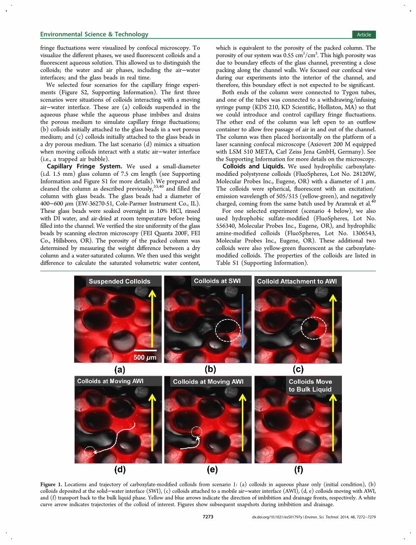
Figure 1. Locations and trajectory of carboxylate-modified colloids from scenario 1: (a) colloids in aqueous phase only (initial condition), (b)colloids deposited at the solid−water interface (SWI), (c) colloids attached to a mobile air−water interface (AWI), (d, e) colloids moving with AWI,and (f) transport back to the bulk liquid phase. Yellow and blue arrows indicate the direction of imbibition and drainage fronts, respectively. A whitecurve arrow indicates trajectories of the colloid of interest. Figures show subsequent snapshots during imbibition and drainage.
Environmental Science & Technology Article
dx.doi.org/10.1021/es501797y | Environ. Sci. Technol. 2014, 48, 7272−72797273
The liquid phase consisted of an aqueous solution of 1 mMCaCl2 and pH 5.5, that is, the same solution we had usedpreviously,40 but here, we further added 0.09 mM (0.01% w/v)of sulforhodamine B dye (Acid Form, laser grade, Dye Content95%, Lot No. 20223EAV, Sigma-Aldrich Co., MO). Thisdye is fluorescent with excitation/emission wavelengths of565/585 nm (red). The CaCl2 and pH were selected to provideconditions of unfavorable attachment of the colloids to the glassbead surfaces, that is, secondary minimum attachment.Experimental Scenarios. Scenario 1: Suspended Colloids
and Dynamic Air−Water Interface. In this scenario, wesuspended the colloids (carboxylate-modified) in the aqueousphase to simulate a situation in which colloids are initially presentin the water itself. We expected that the suspended colloidswould attach to the glass beads under unfavorable attachmentconditions, but then be detached again by the moving air−waterinterfaces in the capillary fringe.Colloids were suspended at a concentration of 3.6 × 10¹¹
particles/L in the aqueous solution (1 mM CaCl2, pH 5.5,0.09 mM sulforhodamine B). This suspension was then infusedinto the initially dry column at a flow rate of 0.012 mL/min(mean pore water velocity of 74 cm/h). This flow rate isrelatively high for the change of the water table level; however,it is less than velocities occurring during Haines jumps. Hainesjumps are the sudden and rapid movements of the infiltrationor drainage fronts caused by the irregular pore geometry inporous media. When the imbibition front reached the middle ofthe microscopic viewing area, we stopped the flow, and uponcomplete flow cessation, we took an image, which represents theinitial condition for this scenario. We could simultaneously observethe fluorescent-green colloids, the fluorescent-red aqueoussolution, the dark-gray background of the air-phase, and thelight-gray background of the glass beads. The flow was thenreversed, with the same rate as the previous infusing flow. Duringthe reversal of the flow, we took images as time series to documentthe continuous events occurring as the colloids were interactingwith the air−water and solid−water interfaces. We made threesubsequent cycles of this imbibition/drainage sequence.Scenario 2: Wet-Deposited Colloids and Dynamic Air−
Water Interface. In this scenario, we deposited the colloids(carboxylate-modified) under unfavorable attachment conditionsonto the glass beads in the porous medium prior to the capillaryfringe fluctuation experiments. This represents a situation in whichcolloids are initially deposited in the capillary fringe and are thenexposed to moving air−water interfaces as the capillary fringefluctuates. To deposit the colloids, the glass bead-filled column wasconnected to Tygon tubing and a peristaltic pump (Ismatec IP4,Glattburg, Switzerland), and the column was preconditionedwith a colloid-free solution (1 mM CaCl2, pH 5.5, and 0.09 mMsulforhodamine B). After discarding the outflow of the pre-conditioning solution, we introduced the colloidal suspension(1 mM CaCl2, pH 5.5, 0.09 mM sulforhodamine B, and colloidconcentration of 3.6 × 10¹¹ particles/L) at a flow rate of0.33 mL/min (mean pore water velocity of 2,036 cm/h) in acirculating loop. The suspension was circulated for 1 h todeposit colloids onto the glass beads, after which the flow wasswitched to a colloid-free solution, and the column was flushedfor 2 h to remove any nonattached colloids.33 The column andthe connecting Tygon tubing were kept water-saturated prior tothe capillary fringe fluctuation experiments.The water-saturated column was then placed under the
confocal microscope, and capillary fringe fluctuations weresimulated as described in scenario 1, except that we used a
colloid-free solution as the aqueous phase. This allowed us tosee how the deposited colloids interacted with the movingair−water interfaces. We first drained the column by withdrawingthe solution, followed by an infusion, and we completed threecycles.
Scenario 3: Dry-Deposited Colloids and Dynamic Air−Water Interface. In this scenario, we deposited colloids(carboxylate-modified) onto the glass beads as in scenario 2; butafter deposition, we flushed out the red color of sulforhodamine Bwith deionized water and dried out the column under a vacuumfor 72 h at room temperature (20−22oC). This scenario representsa situation in which groundwater levels increase and the capillaryfringe penetrates an initially dry soil or sediment layer. Wefollowed the same procedure of capillary fringe fluctuations as that
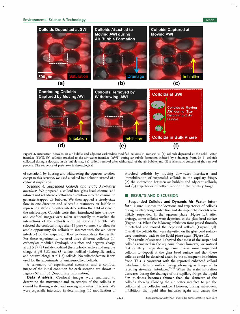
Figure 2. Detachment of deposited carboxylate-modified colloids froma glass bead surface by air bubbles in scenario 2: (a) initial wetdeposition, (b) air bubble formation after a drainage front passage (airbubbles are circled), (c, d) colloids captured and removed by an airbubble at location iii, (e, f) colloids captured and removed by an airbubble at location ii, and (g, h) colloids captured and removed by anair bubble at location i. Blue and yellow arrows indicate the directionof drainage and imbibition fronts, respectively. These figures are inchronological sequence.
Environmental Science & Technology Article
dx.doi.org/10.1021/es501797y | Environ. Sci. Technol. 2014, 48, 7272−72797274
of scenario 1 by infusing and withdrawing the aqueous solution,except in this scenario, we used a colloid-free solution instead of acolloidal suspension.Scenario 4: Suspended Colloids and Static Air−Water
Interface. We prepared a colloid-free glass-bead channel andinfused and withdrew a colloid-free solution into the channel togenerate trapped air bubbles. We then applied a steady-stateflow in one direction and selected a stationary air bubble torepresent a static air−water interface within the field of view inthe microscope. Colloids were then introduced into the flow,and confocal images were taken sequentially to visualize theinteractions of the colloids with the static air bubble. Weselected the confocal image after 14 pore volumes (to allow forample opportunity for colloids to interact with the air−waterinterface) of the suspension flow to demonstrate the results.For these experiments, we used three different colloids: (1)carboxylate-modified (hydrophilic surface and negative chargeat pH 5.5), (2) sulfate-modified (hydrophobic surface and negativecharge at pH 5.5), and (3) amine-modified (hydrophilic surfaceand positive charge at pH 3) colloids. No sulforhodamine B wasused for the experiments of amine-modified colloids.A schematic of experimental scenarios and a confocal
image of the initial condition for each scenario are shown inFigures S2 and S3 (Supporting Information).Data Analysis. Confocal images were analyzed to
determine the movement and trajectories of the colloids ascaused by flowing water and moving air−water interfaces. Wewere especially interested in determining (1) mobilization of
attached colloids by moving air−water interfaces andimmobilization of suspended colloids in the capillary fringe,(2) the interaction between air bubbles and adjacent colloids,and (3) trajectories of colloid motion in the capillary fringe.
■ RESULTS AND DISCUSSION
Suspended Colloids and Dynamic Air−Water Inter-face. Figure 1 shows the locations and trajectories of colloidsduring capillary fringe imbibition and drainage. The colloids wereinitially suspended in the aqueous phase (Figure 1a). Afterdrainage, some colloids were deposited at the glass bead surface(Figure 1b). When the following imbibition front passed through,it detached and moved the deposited colloids (Figure 1c,d).Overall, the colloids that were deposited on the glass bead surfaceswere transferred back to the liquid phase again (Figure 1f).The results of scenario 1 showed that most of the suspended
colloids remained in the aqueous phase; however, we noticedthat capillary fringe drainage could cause some suspendedcolloids to deposit at the glass bead surface and that thesecolloids could be detached again by the subsequent imbibitionfront. This is consistent with the reported enhanced colloiddetachment from a surface during advancing as compared toreceding air−water interfaces.33,40 When the water saturationdecreases during the drainage of the capillary fringe, the liquidfilm thickness becomes thinner than the diameter of thecolloids, thereby allowing the air−water interface to pin thecolloids at the collector surface. However, during subsequentimbibition, the liquid film increases again and causes the
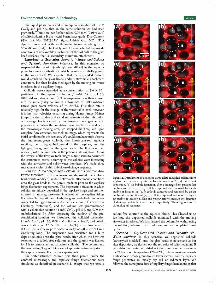
Figure 3. Interaction between an air bubble and adjacent carboxylate-modified colloids in scenario 2: (a) colloids deposited at the solid−waterinterface (SWI), (b) colloids attached to the air−water interface (AWI) during air-bubble formation induced by a drainage front, (c, d) colloidscollected during a decrease in air bubble size, (e) colloid removal after withdrawal of the air bubble, and (f) a schematic concept of the removalprocess. The sequence of parts a−e is chronological.
Environmental Science & Technology Article
dx.doi.org/10.1021/es501797y | Environ. Sci. Technol. 2014, 48, 7272−72797275
colloids to detach and transfer back to the bulk aqueous phase.This pinning in thin water films and subsequent detachmentdue to imbibition has been described by others.41,42
Wet-Deposited Colloids and Dynamic Air−WaterInterface. In this scenario, we first deposited the carboxylate-modified colloids onto the glass beads under unfavorableattachment conditions. Figure 2 illustrates the overall detachmentof wet-deposited colloids in the capillary fringe in a chronologicalsequence. The sequence of images shows the colloids (a) that wereinitially deposited; (b) that were attached to the air−water interfaceof air bubbles at locations i, ii, and iii during the drainage event; and(c−h) that were removed by air bubbles during the followingimbibition event. These confocal images show that (1) air intrudedduring drainage, (2) the air was expelled again during the imbibitionfront, and (3) the deposited colloids were removed from thecapillary fringe only if they appeared to be attached to the air−waterinterfaces.The detachment mechanisms of colloids by an air bubble are
further illustrated in Figure 3. The colloids previously depositedat the solid−water interface (a) were readily detached from thesoil-water interface and attached to a moving air−water interfaceduring air bubble formation (b). These colloids were captured (c),moved along with the moving air−water interface as the air bubblesize decreased (d), and were removed by the withdrawing air−water interface of the air bubble (e). The schematic concept (f)shows the overall colloid removal process. These resultsdemonstrate the effect of the formation/deformation of air-bubbles caused by the capillary fringe fluctuations. Reduction ofair-bubble size during imbibition can happen because of
dissolution of air in the water phase and by increase in waterpressure when the water table rises. Capillary fringe fluctuationsare an important mechanism for colloid detachment fromstationary solid surfaces and subsequent colloid mobilization.The trapped colloids at the air−water interface of the air
bubble can be mobilized only if the air bubble is moving.Colloid removal by moving air−water interfaces has beendemonstrated with flow channels and flat surfaces27−34,40 and isalso relevant for porous media and capillary fringe fluctuations.We also observed colloids sliding along the surfaces of the
glass beads (Figure S5, Supporting Information). These imagesshow that colloids can transfer from one glass bead surface toanother. This movement of colloids along the glass bead surfaceand their transfer from one glass bead to another is consistentwith the “skimming” of colloids under unfavorable attachmentconditions along collector surfaces.43 The downstream prop-agation of near-surface colloids can occur in flow-stagnationzones or grain-to-grain contacts aligned with stagnation zones,44
and our observations provide support for such a mechanism. Theaverage velocity of the colloids sliding along the glass beadsurfaces is 24 ± 24 μm/s, which is 9 times as slow as the meanpore water velocity (74 cm/h = 206 μm/s). The large variationof the colloid velocity indicates a nonuniform skimming of thecolloids along the grain surfaces.
Dry-Deposited Colloids and Dynamic Air−WaterInterface. In scenario 3, colloids were most likely attachedin the primary energy minimum, as we had flushed the columnsafter deposition with deionized water, which should haveremoved all colloids in the secondary minimum. Scenario 3
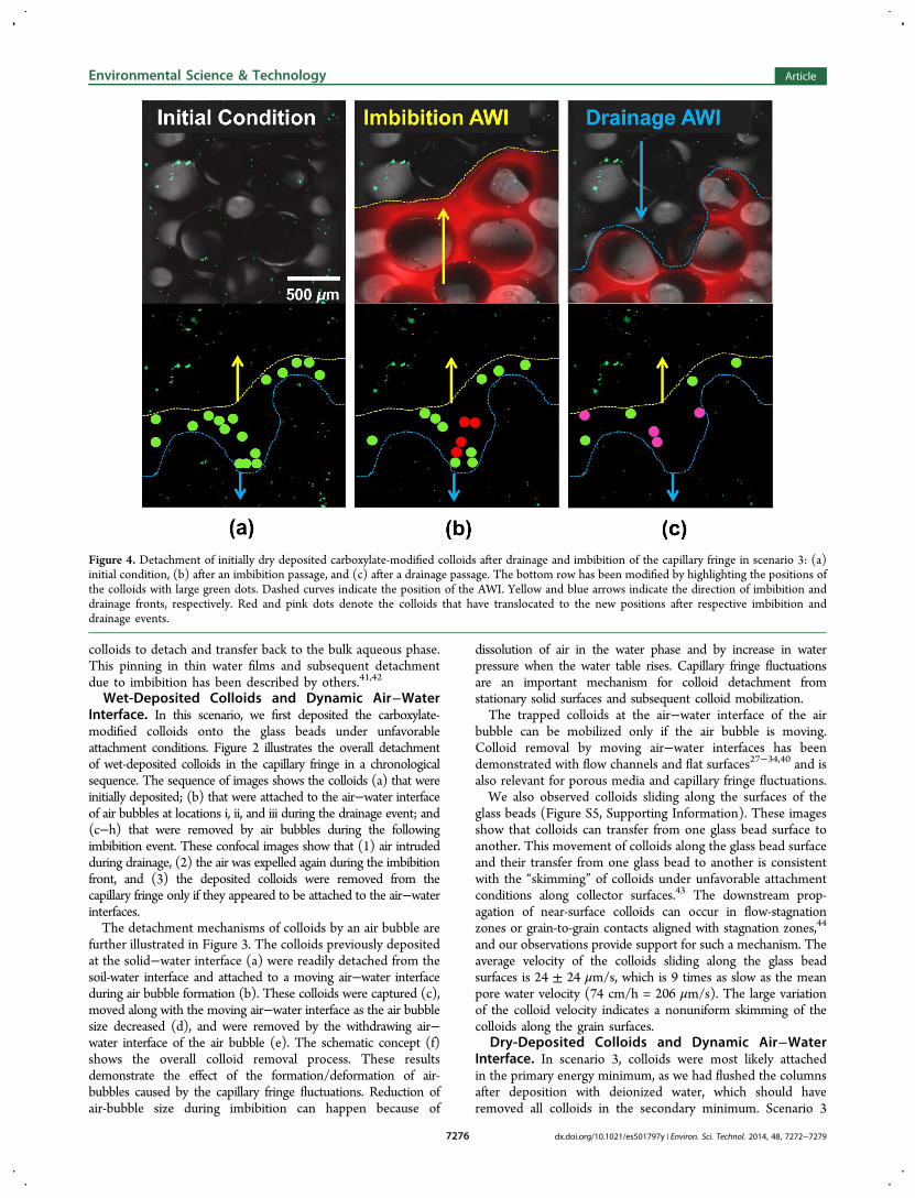
Figure 4. Detachment of initially dry deposited carboxylate-modified colloids after drainage and imbibition of the capillary fringe in scenario 3: (a)initial condition, (b) after an imbibition passage, and (c) after a drainage passage. The bottom row has been modified by highlighting the positions ofthe colloids with large green dots. Dashed curves indicate the position of the AWI. Yellow and blue arrows indicate the direction of imbibition anddrainage fronts, respectively. Red and pink dots denote the colloids that have translocated to the new positions after respective imbibition anddrainage events.
Environmental Science & Technology Article
dx.doi.org/10.1021/es501797y | Environ. Sci. Technol. 2014, 48, 7272−72797276
shows that colloids were readily mobilized by the moving air−water interface during imbibition and drainage (Figure 4). Weobserved (by visual counting) that one cycle of the capillaryfringe fluctuation (imbibition and drainage) caused more than50% of the deposited colloids to detach within the fluctuationregion (Figure 4a vs c). The advancing (imbibition) interfacecaused the deposited colloids to mobilize (see red dots inFigure 4b). These translocated colloids were then removedfrom the capillary fringe by the subsequent receding (drainage)interface. Previous reports30,31,33,34,40 showed that a movingair−water interface is effective in colloid mobilization from flatsurfaces, even when attached in the primary energy minimum,28,34
and our results demonstrate that this also applies to the capillaryfringe.Although some colloids were mobilized by the air−water
interface, other colloids did not move or detach (Figure 4d).We offer two explanations for this observation: (1) colloidsattached under favorable conditions are less likely detached from asurface than are colloids attached under unfavorable conditions, sothere is a better chance that the colloids remain attached,28,34 and(2) colloids are not detached if no air−water solid-interface lineforms. It is likely that some colloids were located in regions, forexample, local depressions, where the air−water interface couldnot form a contact line, and therefore, no capillary force would acton these colloids (Figure S6, Supporting Information). In addition,surface roughness can increase the strength of colloid attachmentrelative to a flat surface,45,46 thereby making them less likely to beremoved by a moving air−water interface.Suspended Colloids and Static Air−Water Interface.
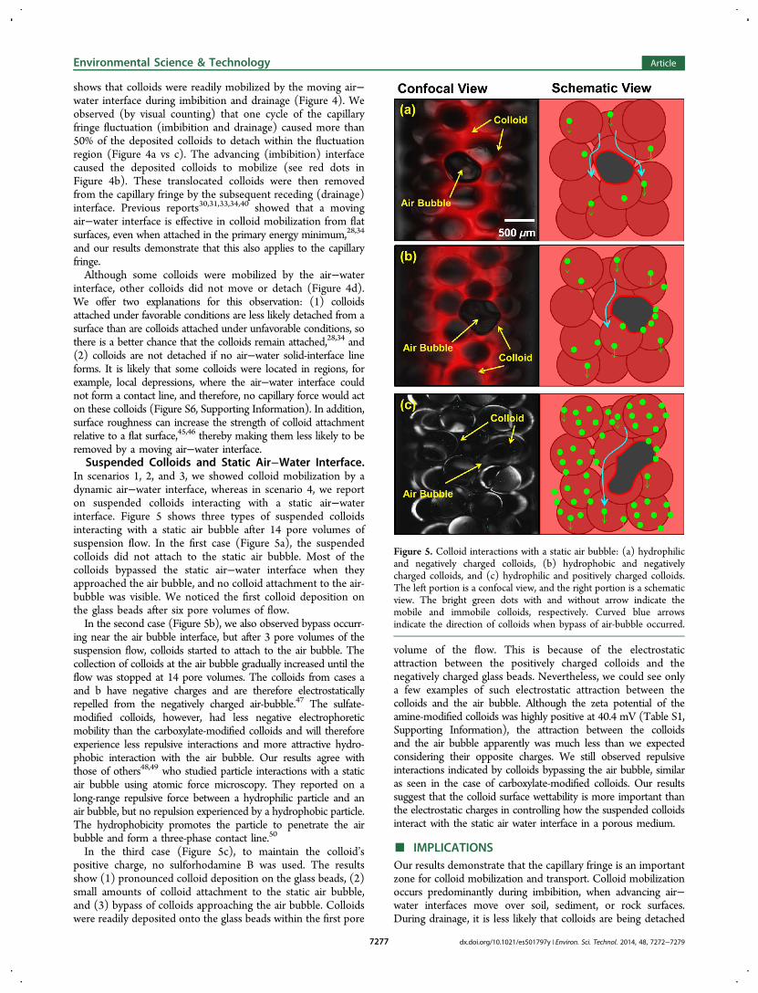
In scenarios 1, 2, and 3, we showed colloid mobilization by adynamic air−water interface, whereas in scenario 4, we reporton suspended colloids interacting with a static air−waterinterface. Figure 5 shows three types of suspended colloidsinteracting with a static air bubble after 14 pore volumes ofsuspension flow. In the first case (Figure 5a), the suspendedcolloids did not attach to the static air bubble. Most of thecolloids bypassed the static air−water interface when theyapproached the air bubble, and no colloid attachment to the air-bubble was visible. We noticed the first colloid deposition onthe glass beads after six pore volumes of flow.In the second case (Figure 5b), we also observed bypass occurr-
ing near the air bubble interface, but after 3 pore volumes of thesuspension flow, colloids started to attach to the air bubble. Thecollection of colloids at the air bubble gradually increased until theflow was stopped at 14 pore volumes. The colloids from cases aand b have negative charges and are therefore electrostaticallyrepelled from the negatively charged air-bubble.47 The sulfate-modified colloids, however, had less negative electrophoreticmobility than the carboxylate-modified colloids and will thereforeexperience less repulsive interactions and more attractive hydro-phobic interaction with the air bubble. Our results agree withthose of others48,49 who studied particle interactions with a staticair bubble using atomic force microscopy. They reported on along-range repulsive force between a hydrophilic particle and anair bubble, but no repulsion experienced by a hydrophobic particle.The hydrophobicity promotes the particle to penetrate the airbubble and form a three-phase contact line.50
In the third case (Figure 5c), to maintain the colloid’spositive charge, no sulforhodamine B was used. The resultsshow (1) pronounced colloid deposition on the glass beads, (2)small amounts of colloid attachment to the static air bubble,and (3) bypass of colloids approaching the air bubble. Colloidswere readily deposited onto the glass beads within the first pore
volume of the flow. This is because of the electrostaticattraction between the positively charged colloids and thenegatively charged glass beads. Nevertheless, we could see onlya few examples of such electrostatic attraction between thecolloids and the air bubble. Although the zeta potential of theamine-modified colloids was highly positive at 40.4 mV (Table S1,Supporting Information), the attraction between the colloidsand the air bubble apparently was much less than we expectedconsidering their opposite charges. We still observed repulsiveinteractions indicated by colloids bypassing the air bubble, similaras seen in the case of carboxylate-modified colloids. Our resultssuggest that the colloid surface wettability is more important thanthe electrostatic charges in controlling how the suspended colloidsinteract with the static air water interface in a porous medium.
■ IMPLICATIONSOur results demonstrate that the capillary fringe is an importantzone for colloid mobilization and transport. Colloid mobilizationoccurs predominantly during imbibition, when advancing air−water interfaces move over soil, sediment, or rock surfaces.During drainage, it is less likely that colloids are being detached
Figure 5. Colloid interactions with a static air bubble: (a) hydrophilicand negatively charged colloids, (b) hydrophobic and negativelycharged colloids, and (c) hydrophilic and positively charged colloids.The left portion is a confocal view, and the right portion is a schematicview. The bright green dots with and without arrow indicate themobile and immobile colloids, respectively. Curved blue arrowsindicate the direction of colloids when bypass of air-bubble occurred.
Environmental Science & Technology Article
dx.doi.org/10.1021/es501797y | Environ. Sci. Technol. 2014, 48, 7272−72797277
from stationary surfaces, but colloids can skim along the surfacesof stationary particles, and previously mobilized and suspendedcolloids can be translocated deeper into the saturated zone. Itis unlikely that stationary air−water interfaces (for example,trapped air bubbles) will capture suspended colloids if thecolloids are hydrophilic and negatively charged. Only hydro-phobic or positively charged colloids can attach to stationary air-bubbles. Although our experimental system, consisting of glassbeads and monodisperse spherical colloids, is a simple model ofthe capillary fringe, we expect that the observed mechanisms holdin a real subsurface system and are even more pronouncedbecause irregularly and angular-shaped colloids will more readilyinteract with moving air−water interfaces. Capillary fringefluctuations are particularly pronounced for perched water tablesnear the soil surface and close to rivers where periodic stagechanges cause groundwater tables to oscillate. Colloidal andcolloid-associated contaminants present in or moving into thecapillary fringe will be affected by the unique mechanismsoperating in this region.
■ ASSOCIATED CONTENT*S Supporting InformationDetails on experimental setup, colloid properties, confocalmicroscopy, figures on experimental setup and additionalconfocal images. This material is available free of charge via theInternet at http://pubs.acs.org.
■ AUTHOR INFORMATIONCorresponding Author*Phone: 1-253-445-4522. E-mail: [email protected].
Present Address∥Presently at: Department of Soil Science, Faculty ofAgriculture, Kasetsart University, Bangkok-10900, Thailand.
NotesThe authors declare no competing financial interest.
■ ACKNOWLEDGMENTSS.A. was financially supported by the Ananda Mahidol Foundation,under the Royal Patronage of H.M. the King, Bhumibol Adulyadej,Thailand. This material is based upon work supported by the U.S.Department of Energy, Office of Science (BER), under AwardNo. DE-FG02-08ER64660. We thank the WSU FranceschiMicroscopy Center for access to their facility and Chris Davittfor help with the use of the confocal microscope. Funding wasfurther provided by the Washington State University AgriculturalResearch Center through Projects 0267 and 0152.
■ REFERENCES(1) Kersting, A. B.; Efurd, D. W.; Finnegan, D. L.; Rokop, D. J.;Smith, D. K.; Thompson, J. L. Migration of plutonium in ground waterat the Nevada Test Site. Nature 1999, 397, 56−59.(2) Novikov, A. P.; Kalmykow, S. N.; Utsunomyia, S.; Ewing, R. C.;Horreard, F.; Merkulov, A.; Clark, S. B.; Tkachev, V.; Myasoedov, B. F.Colloid transport of plutonium in the far-field of the Mayakproduction association, Russia. Science 2006, 314, 638−641.(3) Cheng, T.; Saiers, J. E. Colloid-facilitated transport of cesium invadose-zone sediments: the importance of flow transients. Environ. Sci.Technol. 2010, 44, 7443−7449.(4) Liu, Z.; Flury, M.; Zhang, Z. F.; Harsh, J. B.; Gee, G. W.;Strickland, C. E.; Clayton, R. E. Transport of Europium colloids invadose zone lysimeters at the semi-arid Hanford site. Environ. Sci.Technol. 2013, 47, 2153−2160.
(5) Gao, B.; Dong, Y.; Luo, Y.; Ma, L. Q. Colloid deposition andrelease in soils and their association with heavy metals. Crit. Rev.Environ. Sci. Technol. 2011, 41, 336−372.(6) Sprague, L. A.; Herman, J. S.; Hornberger, G. M.; Mills, A. L.Atrazine adsorption and colloid-facilitated transport through theunsaturated zone. J. Environ. Qual. 2000, 29, 1632−1641.(7) Gjettermann, B.; Petersen, C. T.; Koch, C. B.; Spliid, N. H.;Grøn, C.; Baun, D. L.; Styczen, M. Particle-facilitated pesticideleaching from differently structured soil monoliths. J. Environ. Qual.2009, 38, 2382−2392.(8) Heckrath, G.; Brookes, P. C.; Poulton, P. R.; Goulding, K. W. T.Phosphorus leaching from soils containing different phosphorusconcentrations in the Broadbalk experiment. J. Environ. Qual. 1995,24, 904−910.(9) de Jonge, L. W.; Moldrup, P.; Rubek, G. H.; Schelde, K.;Djurhuus, J. Particle leaching and particle-facilitated transport ofphosphorus at field scale. Vadose Zone J. 2004, 3, 462−470.(10) Vendelboe, A. L.; Moldrup, P.; Heckrath, G.; Jin, Y.; de Jonge,L. W. Colloid and phosphorus leaching from undisturbed soil coressamples along a natural clay gradient. Soil Sci. 2011, 176, 399−406.(11) Steiner, L. D.; Bidwell, V. J.; Di, H. J.; Cameron, K. C.;Northcott, G. L. Transport and modeling of estrogenic hormones in adairy farm effluent through undisturbed soil lysimeters. Environ. Sci.Technol. 2010, 44, 2341−2347.(12) Zou, Y.; Zheng, W. Modeling manure colloid-facilitatedtransport of the weakly hydrophobic antibiotic florfenicol in saturatedsoil columns. Environ. Sci. Technol. 2013, 47, 5185−5192.(13) Sen, T. K. Processes in pathogenic biocolloidal contaminantstransport in saturated and unsaturated porous media: a review. WaterAir Soil Pollut. 2011, 216, 239−256.(14) Ryan, J. N.; Elimelech, M. Colloid mobilization and transport ingroundwater. Colloids Surf. Physicochem. Eng. Aspects 1996, 107, 1−56.(15) Bradford, S. A.; Torkzaban, S. Colloid transport and retention inunsaturated porous media: a review of interface-, collecter-, and pore-scale processes and models. Vadose Zone J. 2008, 7, 667−681.(16) Flury, M.; Qiu, H. Modeling colloid-facilitated contaminanttransport in the vadose zone. Vadose Zone J. 2008, 7, 682−697.(17) Wan, J. M.; Wilson, J. L. Colloid transport in unsaturated porousmedia. Water Resour. Res. 1994, 30, 857−864.(18) Crist, J. T.; McCarthy, J. F.; Zevi, Y.; Baveye, P. C.; Troop, J. A.;Steenhuis, T. S. Pore-scale visualization of colloid transport andretention in partially saturated porous media. Vadose Zone J. 2004, 3,444−450.(19) Zevi, Y.; Gao, B.; Zhang, W.; Morales, V. L.; Cakmak, M. E.;Medrano, E. A.; Sang, W. J.; Steenhuis, T. S. Colloid retention at themeniscus−wall contact line in an open microchannel. Water Res. 2012,46, 295−306.(20) Weisbrod, N.; Niemet, M. R.; Selker, J. S. Light transmissiontechnique for the evaluation of colloidal transport and dynamics inporous media. Environ. Sci. Technol. 2003, 37, 3694−3700.(21) Bridge, J. W.; Banwart, S. A.; Heathwaite, A. L. High-resolutionmeasurement of pore saturation and colloid removal efficiency inquartz sand using fluorescence imaging. Environ. Sci. Technol. 2007, 41,8288−8294.(22) Cheng, T.; Saiers, J. E. Mobilization and transport of in situcolloids during drainage and imbibition of partially saturatedsediments. Water Resour. Res. 2009, 45, W08414 DOI: 10.1029/2008WR007494.(23) Jost, D.; Winter, J.; Gallert, C. Distribution of aerobic motile andnon-motile bacteria within the capillary fringe of silica sand. Water Res.2010, 44, 1279−1287.(24) SSSA Glossary of soil science terms; SSSA, Madison, WI, on-line athttp://www.soils.org/sssagloss/; accessed in December, 2013, 2007.(25) Haberer, C. M.; Rolle, M.; Cripka, O. A.; Grathwohl, P. Oxygentransfer in a fluctuating capillary fringe. Vadose Zone J. 2012, 11,10.2136/vzj2011.0056.(26) Zhang, M. H.; Geng, S.; Ustin, S. L. Quantifying the agriculturallandscape and assessing spatio-temporal patterns of precipitation andgroundwater use. Landscape Ecol. 1998, 13, 37−53.
Environmental Science & Technology Article
dx.doi.org/10.1021/es501797y | Environ. Sci. Technol. 2014, 48, 7272−72797278
(27) Leenaars, A. F. M.; O’Brien, S. B. G. Particle removal fromsilicon substrates using surface tension forces. Philips J. Res. 1989, 44,183−209.(28) Noordmans, J.; Wit, P. J.; van der Mei, H. C.; Busscher, H. J.Detachment of polystyrene particles from collector surfaces by surfacetension forces induced by air-bubble passage through a parallel plateflow chamber. J. Adhes. Sci. Technol. 1997, 11, 957−969.(29) Gomez-Suarez, C.; Noordmans, J.; van der Mei, H. C.; Busscher,H. J. Removal of colloidal particles from quartz collector surfaces assimulated by the passage of liquid−air interfaces. Langmuir 1999, 15,5123−5127.(30) Gomez-Suarez, C.; van der Mei, H. C.; Busscher, H. J. Airbubble-induced detachment of positively and negatively chargedpolystyrene particles from collector surfaces in a parallel-plate flowchamber. J. Adhes. Sci. Technol. 2000, 14, 1527−1537.(31) Gomez-Suarez, C.; Noordmans, J.; van der Mei, H. C.; Busscher,H. J. Air bubble-induced detachment of polystyrene particles withdifferent sizes from collector surfaces in a parallel plate flow chamber.Colloids Surf. 2001, 186, 211−219.(32) Lazouskaya, V.; Wang, L.-P.; Gao, H.; Shi, X.; Crymmek, K.; Jin,Y. Pore-scale investigation of colloid retention and mobilization in thepresence of a moving air−water interface. Vadose Zone J. 2011, 10,1250−1260.(33) Aramrak, S.; Flury, M.; Harsh, J. B. Detachment of depositedcolloids by advancing and receding air-water interfaces. Langmuir2011, 27, 9985−9993.(34) Sharma, P.; Flury, M.; Zhou, J. Detachment of colloids from asolid surface by a moving air-water interface. J. Colloid Interface Sci.2008, 326, 143−150.(35) van Nierop, E. A.; Stijnman, M. A.; Hilgenfeldt, S. Shape-induced capillary interactions of colloidal particles. Europhys. Lett.2005, 72, 671−677.(36) Lehle, H.; Noruzifar, E.; Oettel, M. Ellipsoidal particles at fluidinterfaces. Eur. Phys. J. E: Soft Matter Biol. Phys. 2008, 26, 151−160.(37) Shang, J.; Flury, M.; Deng, Y. Force measurements betweenparticles and the air−water interface: Implications for particlemobilization in unsaturated porous media. Water Resour. Res. 2009,45, W06420 DOI: 10.1029/2008WR007384.(38) Danov, K. D.; Kralchevsky, P. A. Capillary forces betweenparticles at a liquid interface: General theoretical approach andinteractions between capillary multipoles. Adv. Colloid Interface Sci.2010, 154, 91−103.(39) Chatterjee, N.; Lapin, S.; Flury, M. Capillary forces betweensediment particles and an air-water interface. Environ. Sci. Technol.2012, 46, 4411−4418.(40) Aramrak, S.; Flury, M.; Harsh, J. B.; Zollars, R. L.; Davis, H. P.Does colloid shape affect detachment of colloids by a moving air−water interface? Langmuir 2013, 29, 5770−5780.(41) Wan, J. M.; Tokunaga, T. K. Film straining of colloids inunsaturated porous media: conceptual model and experimental testing.Environ. Sci. Technol. 1997, 31, 2413−2420.(42) Shang, J.; Flury, M.; Chen, G.; Zhuang, J. Impact of flow rate,water content, and capillary forces on in situ colloid mobilizationduring infiltration in unsaturated sediments. Water Resour. Res. 2008,44, W06411 DOI: 10.1029/2007WR006516.(43) Ma, H.; Pazmino, E. F.; Johnson, W. P. Surface heterogeneity onhemisphere-in-cell model yields all experimentally observed nonstraining colloid retention mechanisms in porous media in thepresence of energy barriers. Langmuir 2011, 27, 14982−14994.(44) Johnson, W. P.; Hilpert, M. Upscaling colloid transport andretention under unfavorable conditions: Linking mass transfer to poreand grain topology. Water Resour. Res. 2013, 49, 10.1002/wrcr.20433.(45) Shen, C.; Wang, F.; Li, B.; Jin, Y.; Wang, L. P.; Huang, Y.Application of DLVO energy map to evaluate interactions betweenspherical colloids and rough surfaces. Langmuir 2012, 28, 14681−14692.(46) Shen, C.; Lazouskaya, V.; Zhang, H.; Wang, F.; Li, B.; Jin, Y.;Huang, Y. Theoretical and experimental investigation of detachment of
colloids from rough collector surfaces. Colloids Surf. Physicochem. Eng.Aspects 2012, 410, 98−110.(47) Takahashi, M. ζ Potential of microbubbles in aqueous solutions:electrical properties of the gas−water interface. J. Phys. Chem. B 2005,109, 21858−21864.(48) Preuss, M.; Butt, H. Direct measurement of particle−bubbleinteractions in aqueous electrolyte: dependence on surfactant.Langmuir 1998, 14, 3164−3174.(49) Ren, S.; Masliyah, J.; Xu, Z. Studying bitumen−bubbleinteractions using atomic force microscopy. Colloids Surf. Physicochem.Eng. Aspects 2014, 444, 165−172.(50) Fielden, M. L.; Hayes, R. A.; Ralston, J. Surface and capillaryforces affecting air bubble−particle interactions in aqueous electrolyte.Langmuir 1996, 12, 3721−3727.
Environmental Science & Technology Article
dx.doi.org/10.1021/es501797y | Environ. Sci. Technol. 2014, 48, 7272−72797279