coded optical time domain reflectometry : principle and applications
TRANSCRIPT

Coded optical time domain reflectometry : principle and applications Namkyoo Park*a, Jeonghwan Leea, Jonghan Parka, Jae Gwang Shima, Hosung Yoonb, Jin Hee Kimb,
Kyoungmin Kimc, Jae-Oh Byunc, Gabriele Bologninid, Duckey Leea, Fabrizio Di Pasqualed
aPhotonic Systems Laboratory, School of EECS, Seoul National University, Seoul, 151-744, Korea
bFTTH Solution Development Department, Network Infra Lab., KT Corp., Daejeon, 305-811, Korea cLuxpert Technologies Co., Ltd., Seoul, 152-768, South Korea
dScuola Superiore Sant’Anna, via G Moruzzi 1, 56124 Pisa, Italy
ABSTRACT
In this paper, we will briefly outline our contributions for the physical realization of coded OTDR, along with its principles and also highlight recent key results related with its applications. For the communication network application, we report a multi-port / multi-wavelength, high-speed supervisory system for the in-service monitoring of a bidirectional WDM-PON system transmission line up to 16 ports x 32 nodes (512 users) capacity. Monitoring of individual branch traces up to 60 km was achieved with the application of a 127-bit simplex code, corresponding to a 7.5dB SNR coding gain effectively reducing the measurement time about 30 times when compared to conventional average mode OTDR. Transmission experiments showed negligible penalty from the monitoring system to the transmission signal quality, at a 2.5Gbps / 125Mbps (down / up stream) data rate. As an application to sensor network, a Raman scattering based coded-OTDR distributed temperature sensor system will be presented. Utilizing a 255-bit Simplex coded OTDR together with optimized sensing link (composed of cascaded fibers with different Raman coefficients), significant enhancement in the interrogation distance (19.5km from coding gain, and 9.6km from link-combination optimization) was achieved to result a total sensing range of 37km (at 17m/3K spatial/temperature resolution), employing a conventional off-shelf low power (80mW) laser diode.
Keywords: Optical time domain reflectometery (OTDR), optical coding, fiber to the home (FTTH), wavelength division multiplexed passive optical network (WDM-PON), distributed temperature sensor (DTS)
1. INTRODUCTION Quite simple in its working principle based on scattering power measurement, Optical Time Domain Reflectometry (OTDR) has been widely adopted in the field for the characterization of optical fibers. Application of the technology for various purposes also has been proposed, including communication line interrogation and distributed sensing, each targeting for different measurands. Differ in its applications, still all the OTDR based technologies / applications share the same technical bottleneck to counter: SNR (dynamic range) and spatial resolution limit / tradeoff, dictated by the peak power and pulsewidth of the probe pulse.
In order to overcome this technical bottleneck, various coding techniques have been suggested [1-6]. In principle, these methods utilize coded sequences of unit short pulse to obtain a higher trace level and thus better SNR from the increased effective pulsewidth / power for the probe, and at the same time to keep the spatial resolution of the short unit pulse. The final OTDR trace, in conventional shape but with improved SNR, can then be restored from the coded traces by decoding processes. In the early stage of the development of coded OTDR, the use of correlation techniques - commonly used in wireless radars have been suggested, employing PRBS (periodic pseudo-random bit sequences) [1, 2]. Still, with the problem associated with dynamic range and receiver saturation [7], this approach was found to be unsuitable for the practical applications. Overcoming the limitations of PRBS coded OTDR, the complementary correlation OTDR (cc-OTDR) based on the complementary pairs of Golay codes was suggested [3]. Also proposed after was the coding technique based on simplex codes [4], with the 3dB SNR improvement over the OTDR employing Golay codes. Still, the description in the art was limited to the prediction of coding gain only - based on the simple argument comparing it to the simplex codes in the spatial domain [8, 9] - without any systematic analysis for the OTDR performance or verification of the concept with numerical / experimental means.
Invited Paper
Passive Components and Fiber-based Devices IV,edited by Ming-Jun Li, Jianping Chen, Satoki Kawanishi, Ian Hugh White,
Proc. of SPIE Vol. 6781, 678129, (2007) · 0277-786X/07/$18 · doi: 10.1117/12.746977
Proc. of SPIE Vol. 6781 678129-1

Recently we have demonstrated the use of coding gain for above stated problem with the deeper investigations on optimal optical coding sets, and also with the implementation of high-speed electronics [5, 6]. Without any fundamental modifications in the OTDR hardware or measurement penalties in the spatial resolution, Simplex coded OTDR provided significant enhancement in the SNR value approaching the theoretical coding gain of 10dB. Using a set of coded pulse sequences instead of conventional isolated single pulse, it was possible to effectively increase the total probe pulse power while retaining the spatial resolution provided by the isolated pulsewidth - thus to achieve increased SNR.
In this paper, we will briefly outline our contributions for the physical realization of coded OTDR, along with its principles. We will also summarize recent key results related with its applications: 1) high-speed surveillance system for 512 users WDM-PON system and 2) Raman-based, long-reach distributed temperature sensor (DTS) systems.
For the communication network application (1), we report a multi-port / multi-wavelength, high-speed supervisory system for the in-service monitoring of a bidirectional WDM-PON system transmission line. First clearly identifying unique requirements for the surveillance of a real field WDM-PON system, we define the architecture for the supervisory system and then blend the most up-to-date technologies (Simplex coding, tunable source, and RFTS) to achieve a successful interrogation of a transmission line up to 16 ports x 32 nodes (512 users) capacity. Monitoring of individual branch traces up to 60 km was achieved with the application of a 127-bit simplex code, corresponding to a 7.5dB SNR coding gain effectively reducing the measurement time about 30 times when compared to conventional average mode OTDR. Transmission experiments showed negligible penalty from the monitoring system to the transmission signal quality, at a 2.5Gbps / 125Mbps (down / up stream) data rate.
As an application to sensor network, a Raman scattering based coded-OTDR distributed temperature sensor system is summarized. Utilizing a 255-bit Simplex coded OTDR together with optimized sensing link (composed of cascaded fibers with different Raman coefficients), significant enhancement in the interrogation distance (19.5km from coding gain, and 9.6km from link-combination optimization) was achieved to result a total sensing range of 37km (at 17m/3K spatial/temperature resolution), employing a conventional off-shelf low power (80mW) laser diode.
2. PRINCIPLE
S-matrix has been widely used for the purpose of noise reduction in optical spectrometries [8, 9]. Briefly stated, the S-matrix is a unipolar matrix composed of 1’s and 0’s, and the rows of this matrix are called simplex codes. It can be also derived from a normalized Hadamard matrix which is a bipolar matrix composed of 1’s and –1’s [9]. S-matrix has been generally used to detect optical power signals due to its unipolar characteristics, although it provides lower efficiency than the Hadamard matrix. The operation using Hadamard- or S-matrix is called Hadamard transform, and there exists a fast algorithm for its calculation - Fast Hadamard Transform (FHT) [10]. The Hadamard transform technique has been applied to the spectrometries by using a spatial mask which consists of holes and blocks [9].
Instead of using the spatial mask, the technique also can be applied to an OTDR system by turning the laser on and off in the time domain, to represent 1’s and 0’s in the S-matrix. As an example, Fig. 1 illustrates time domain equivalent of S-matrix (order 3). First we define ψ1(t) to be an OTDR trace measured with a single probe pulse . In order to apply the Hadamard transform to the time domain, we also define time-shifted pulses P2(t)=P1(t-τ) and P3(t)=P1(t-2τ), where τ is the pulsewidth of P1(t). Correspondingly, ψ2(t) and ψ3(t) represent the traces measured with the probe pulse P2(t) and P3(t). From Fig. 1(a), it is clear now that relationships below should hold between the time-delayed pulses / traces.
ψ2(t)=ψ1(t-τ), ψ3(t)=ψ1(t-2τ) (1)
Under these arrangements, three coded traces η1(t), η2(t), and η3(t) can be measured by launching a coded pulse sequences into the fiber, as illustrated in Fig. 1(b) and written in equation (2). We note that here e1(t), e2(t), and e3(t) represent amplitudes of receiver noise added in each measurement.
P1(t)+P3(t) η1(t)=ψ1(t)+ψ3(t)+e1(t)
P2(t)+P3(t) η2(t)=ψ2(t)+ψ3(t)+e2(t) (2)
P1(t)+P2(t) η3(t)=ψ1(t)+ψ2(t)+e3(t)
Proc. of SPIE Vol. 6781 678129-2

(t) J1(t)
1(t)+1(t) JL
I(t)+I(t)
W1(t)
y(t)
Y13(t)
(a)
Wl(t)+Y(t)fLflJT
(b)
Fig. 1. Example of the time domain application of the Hadamard transform technique using a S-matrix of order 3
Re-writing above equation set utilizing the S-matrix, we get:
1 1 1
2 2 2
3 3 3
( ) ( ) ( ) 1 0 1( ) ( ) ( ) , 0 1 1( ) ( ) ( ) 1 1 0
t t e tt t e tt t e t
η ψη ψη ψ
⎛ ⎞ ⎛ ⎞ ⎛ ⎞ ⎛ ⎞⎜ ⎟ ⎜ ⎟ ⎜ ⎟ ⎜ ⎟= + =⎜ ⎟ ⎜ ⎟ ⎜ ⎟ ⎜ ⎟⎜ ⎟ ⎜ ⎟ ⎜ ⎟ ⎜ ⎟⎝ ⎠ ⎝ ⎠ ⎝ ⎠ ⎝ ⎠
S S (3)
In order to recover the conventional OTDR trace ψ1(t), the measured 3 (coded) traces are processed with inverse Hadamard transform, utilizing following equations (here, ( )i tψ) represents the estimate of ψi (t).
1 1 1
12 2 2
3 3 3
( ) ( ) 1 1 1 ( )1( ) ( ) 1 1 1 ( )2
( ) ( ) 1 1 1 ( )
t t tt t tt t t
ψ η ηψ η ηψ η η
−
−⎛ ⎞ ⎛ ⎞ ⎛ ⎞⎛ ⎞⎜ ⎟ ⎜ ⎟ ⎜ ⎟⎜ ⎟= = −⎜ ⎟ ⎜ ⎟ ⎜ ⎟⎜ ⎟⎜ ⎟ ⎜ ⎟ ⎜ ⎟⎜ ⎟−⎝ ⎠ ⎝ ⎠ ⎝ ⎠⎝ ⎠
S
)
)
) (4)
{ }
{ }
{ }
1 2 31 1 2 3 1
1 2 32 1 2 3 2
1 2 33 1 2 3 3
( ) ( ) ( )1( ) ( ) ( ) ( ) ( )2 2
( ) ( ) ( )1( ) ( ) ( ) ( ) ( )2 2
( ) ( ) ( )1( ) ( ) ( ) ( ) ( )2 2
e t e t e tt t t t t
e t e t e tt t t t t
e t e t e tt t t t t
ψ η η η ψ
ψ η η η ψ
ψ η η η ψ
− += − + = +
− + += − + + = +
+ −= + − = +
)
)
)
(5)
Averaging these estimates after inversely time-shifting them with multiples of τ - meanwhile using the time relationships in equation (1) - we finally obtain the restored trace:
1 2 3 1 2 3
1
1 2 3 1 2 3
( ) ( ) ( 2 ) ( ) ( ) ( )( )3 6
( ) ( ) ( ) ( 2 ) ( 2 ) ( 2 )6
t t t e t e t e tt
e t e t e t e t e t e t
ψ ψ τ ψ τ ψ
τ τ τ τ τ τ
+ + + + − += + +
− + + + + + + + + + − +
) ) )
(6)
Proc. of SPIE Vol. 6781 678129-3

11
10
98
D 76
(9 5C
00 32
00 64 128 192 256 320 384 448 512
Code Length
From this, we can also get the mean square error (MSE) of the restored trace,
{ } { } ( ){ } ( ) ( )( )
2 221 2 3
1
2 2
( ) ( ) ( 2 ) 9 1( ) ,3 36 4
( ) 0, ( ) 1, 2,3
( ) ( ) 0 or , 0
i i
i j
t t tE t
E e t E e t i
E e t e t i j i j
ψ ψ τ ψ τ σψ σ
ς ς σ
ς ς
⎧ ⎫+ + + +⎪ ⎪⎛ ⎞− = =⎨ ⎬⎜ ⎟⎝ ⎠⎪ ⎪⎩ ⎭
+ = + = =
+ = ≠ = ≠
) ) )
Q (7)
where we used the following assumptions - ei (t)’s are uncorrelated, zero-mean random processes with variance σ 2. Since the restored trace in eq. (6) was obtained from the measurement of 3 coded traces, we have to compare its noise power to that of the conventional OTDR with N=3 (averaging of 3 identical single-pulse measurements). As the MSE of N=3 averaging is simply σ 2 /3, we get the following SNR improvement for the sc-OTDR, at the code length L = 3.
2 2 23 4 3σ σ
= (8)
The described time domain algorithm can be easily extended to the general case of code length L, while the above procedure depicts the specific case of code length 3 [6]. Then the coding gain for the general code length L becomes
( )
2 2
214
21L
L LLσ σ +
=+
(9)
Fig. 2 illustrates the amount of SNR enhancement of sc-OTDR compared to conventional averaging OTDR, as a function of the code length. It is worth to note that this enhancement factor is identical to the result which can be found in spatial domain analysis of Hadamard transform, for spectrometry applications [9].
Fig. 2. Amount of SNR enhancement (coding gain) using Hadamard transform technique, as a function of the code length
3. COMMUNICATION NETWORK APPLICATION 3.1 Introduction
Considering the huge amount of involved user counts and data traffic amount, the supervisory system for the WDM-PON application now calls for a serious challenge - increase of measurement time with the large number of users to be monitored, requirement of different wavelength for each user, and security of expansion capability considering cost considering cost issues and future expansions [11, 12]. Solutions for the above stated problems have existed in the past, but in a very limited form providing only partial solutions to support the total number of users less than several of 10s [13-15]. The natural extension for the following evolution will be a multi-port, multi-wavelength system combining the
Proc. of SPIE Vol. 6781 678129-4

RFTS and an AWG together with a tunable OTDR, which will enable coverage of hundreds of users; sharing the system cost, but at the expense of increased network surveillance time.
The other approach can be taken is the use of recently developed OTDR coding technology [4-6]. For this work, as much as 7.5dB coding gains in the SNR were achieved with the application of 127bit Simplex coding to the OTDR. Considering that the coding gain also can be utilized to reduce the measurement time rather than the dynamic range improvement, significant reductions in the measurement time can be obtained (for example, from 3 minutes to 5.6 seconds with a 127 bit code, ignoring the associated code processing time). Assuming a 16 port x 32 node WDM-PON architecture which we illustrate as an example in this work, this corresponds to a measurement time of less than an hour for the whole network, including 512 users, instead of a day. In this section, we demonstrate a multi-port, multi-wavelength supervisory system for the transmission line monitoring of bidirectional WDM-PON systems. Coded OTDR based on simplex coding, tunable source and optical switch was applied to demonstrate fast and reliable interrogation of transmission line up to 16 port x 32 node (512 users) capacity.
3.2 Experiments
Figure 3 shows the schematic diagram of experimental setup with the constructed WDM-PON supervisory system in which a high speed DSP processor and a parallel data interface were employed in the hardware / firmware to facilitate matrix operations in the decoding process [16]. Network elements of the WDM-PON system include: the optical line terminal (OLT), feeder fiber, remote node (RN), distribution fiber, and subscribers. OLTs in the central office (CO), were connected to corresponding WDM-PON links through a fiber distribution panel (FDP). A 1x16 optical switch (insertion loss = 1dB) was employed, to share the S-band supervisory system for different links operating at signal wavelength bands (C/L). The upgrade of the system for the accommodation of more WDM-PON links can be made by replacing the optical switch with one of higher port-number counts. SMFs of 10 km and 20 km were used in link No. 7 and link No. 15, respectively, for the verification of the supervisory system in the real set-up, instead of the full WDM-PON link. For link No. 1, a feeder fiber of 20 km (40 km), and a distribution fiber of 1 km and 10 km (20 km) were used to connect subscribers 4 and 25, respectively. For the downstream, L-band (1573.95nm~1598.75nm) signals modulated in the CO were multiplexed by a 32 channel AWG of 100 GHz spacing (insertion loss = 6~7dB depending on channel number). The multiplexed signals were, then, de-multiplexed with a 1×32 AWG at RN after the feeder fiber, and sent to each subscriber. For the upstream transmission, C-band (1533.40~1558.20nm) DFB lasers were used.
SM F 20(40) km
AW G
Subscriber 1
Subscriber 32
SM F1 km
SM F10(20) km
Subscriber 4
SS
SS
SS
SS
LC
Subscriber 25
DFB
RX
125 -M b /s data
RN
C,L
C,L
C,L
C,L
Tunable O TDR
APD
SO AS-TLS
TIAD
SP
Supervisory system
A/D
LC
TRX25
TLS
RX
TRX 1
AW G
TRX 32
2.5- G b/s data
OLT 1
OLT16
C,LS
W D M -PON LINK 1FD P
SM F 10km W D M -PO N LINK 7
SM F 20km W DM -PO N LINK 15
W DM -PO N LINK 16
C,LS
C,LS
C,LS
Central O ffice
Fig. 3. Schematic of the supervisory system and experimental setup for in-service monitoring of link faults in a bidirectional WDM-PON system (down-stream signal at L-band, up-stream signal at C-band, and supervisory system at S-band)
For the generation of the probe pulse (isolated, or coded) in the supervisory system, an S-band tunable laser (wavelength tuning speed for the worst case : from the last (32) to first channel ~ 0.3 second) and a modulated C/S-band semiconductor optical amplifier (SOA) were used in combination, at a wavelength of 1458.15~1481.76 nm, utilizing the cyclic property of the AWG (FSR of ~36nm, 3dB BW of 0.4nm, and maximum integrated crosstalk of -23dB). A C-L/S
Proc. of SPIE Vol. 6781 678129-5

band WDM coupler (C/L→S isolation of >12dB and S→C/L isolation of >30dB) was employed in the FDP to couple the probe pulse and multiplexed downstream signals. WDM couplers were also placed after all the distribution fibers, to suppress the out-band crosstalk from probe pulses to subscriber receiver units.
3.3 Results
Fig. 4 shows the measured traces for the link numbers 7 and 15 out of 16 connected links. The pulse width of the probe pulse was 500 ns. The wavelength was set at 1528.74 nm. It is worth noting again, the extension / upgrade to the WDM-PON system of larger link counts should be easy with the replacement of the optical switches.
0 10 20 305
10152025303540
(a) Port 7
Loss
[dB
]
Distance [km]
10km
0 10 20 305
10152025303540
(b) Port 15
Loss
[dB
]
Distance [km]
20km
Fig. 4. OTDR traces measured to show multi-port function
0 10 20 305
1015202530
(a) Ch. 4
Distance [km]
Loss
[dB
]
20km 1km
0 10 20 305
1015202530
(b) Ch. 25
Distance [km]
20kmLo
ss [d
B]
10km
0 10 20 305
1015202530
(c) Ch. 4
Distance [km]
Loss
[dB
]
20km 1km
0 10 20 305
1015202530
-10 0 10 20 30 40
0.040
0.045
0.050
0.055
Distance [km]
(d) Ch. 25
Loss
[dB
]
20km 10km
Fig. 5. Measured loss traces using conventional OTDR (a, b) and 31-bit coded-OTDR (c, d)
(Inset: the first codeword of the 31-bit simplex code pattern as SOA output)
Channel 4 and channel 25 of link 1 were used for the demonstration of channel selection. The probe pulse wavelength and SMF link length for channel 4 (25) were 1460.5nm (1476.44nm) and 1km (10km), respectively. It is worth mentioning that the S-band TLS was directly modulated with a sinusoid to reduce the coherent fading noise [17]. With the probe pulse width of 100ns and a peak power of 10dBm, the spatial resolution and accuracy of the measurement was about 10m and 2m, respectively. Fig. 5 shows measured loss traces of channels 4 and 25, using the OTDR in a conventional averaging mode (a, b) and in a coded mode (c, d. 31-bit Simplex code, for short-reach application). The averaging number for the OTDR trace, in a conventional single-pulse / 31-bit coded pulse mode, was 3,100 times / 100 times (per each codeword), respectively. Evidently, it can be seen from the figures, a much clearer identification for the distribution fiber after the 10km of feeder fiber was observed with the application of the coding technology. As much as 4.8dB of the SNR enhancement (or 2.4dB in dynamic range) was observed, in excellent agreement with the theoretically predicted values [4-6]. As mentioned earlier, this coding gain also can be used to reduce the required link interrogation time for the measurements at a fixed dynamic range, instead of the trace noise reduction. For example assuming 30km of link length for every user, with 31-bit coded-OTDR it takes about 8 minutes to interrogate all the 512 user lines (excluding pulse guard time. Per user, probing time = 10 ㎲/㎞×30 ㎞×3,100 = 0.93 seconds). To compare, for the conventional OTDR it takes about 72 minutes to cover all the 512 users and to achieve the same level of SNR as that of coded OTDR (per user, 10㎲/㎞×30㎞×28,200 = 8.46 seconds).
Proc. of SPIE Vol. 6781 678129-6

0 10 20 30 40 50 60 70 80 90 10005
101520253035
(a) conventional OTDR
Loss
[dB
]
40km 20km
0 10 20 30 40 50 60 70 80 90 10005
101520253035
Distance [km]
(b) 127-bit coded-OTDR
Loss
[dB
]
40km 20km
Fig. 6. Link loss traces using a) the conventional OTDR and b) the 127-bit C-OTDR for long reach (60km20km) application
To measure the possible signal degradation from the existence of an in-service probing pulse in the transmission line, the BER measurements have been carried out both for up-stream and down-stream data traffic. For the down-stream signal, a tunable laser set at 1593.56nm was used with an external modulator (2.5Gb/s, 223-1 PRBS, NRZ). For the up-stream transmission, a 1552.52nm DFB laser was used (125Mb/s, 223-1 PRBS, NRZ). Fig. 7 shows the results of measurements: BER curves in a back-to-back condition without OTDR pulses, the BER after 60km of transmission link without OTDR pulses, and the BER after the transmission with OTDR pulses. No transmission penalties in the down/up stream signals from the in-service monitoring were observed (for both the conventional OTDR mode and the coded OTDR mode).
-39 -38 -37 -36 -35 -34 -33 -321E-10
1E-9
1E-8
1E-7
1E-6
1E-5
1E-4
1E-3
after transmission
back-to-back
back-to-back OTDR off conventional on_12.5dBm 127-b coded on_12.5dBm
BER
Received Power [dBm]
(a) Downstream
-40 -39 -38 -37 -36 -35 -341E-10
1E-9
1E-8
1E-7
1E-6
1E-5
1E-4
1E-3
(b) Upstream
BER
Received Power [dBm]
back-to-back
after transmission
Fig. 7. BER characteristics of a) downstream (2.5Gbps) and b) upstream (125Mbps) signals.
No transmission penalty was observed with the OTDR operation
3.4 Discussion
In this section, we proposed / demonstrated a multi- port / -wavelength supervisory system for in-service transmission line monitoring of a bidirectional WDM-PON system. Monitoring of individual branch traces up to 60 km was achieved with the application of a 127-bit simplex code, corresponding to a 7.5dB SNR coding gain effectively reducing the measurement time about 30 times when compared to conventional OTDR. Transmission experiments showed negligible penalty from the monitoring system to the transmission signal quality, at a 2.5Gbps / 125Mbps (down / up) data rate.
Proc. of SPIE Vol. 6781 678129-7

4. SENSOR NETWORK APPLICATION 4.1 Introduction
Distributed Temperature Sensors (DTS) based on Spontaneous Raman Scattering (SRS) in Single Mode Fibers (SMF) have been intensively studied in previously published research [18, 19]. In the majority of the proposed schemes, an Optical Time Domain Reflectometer (OTDR) is used to monitor the temperature dependent backscattered light, for assessment of temperature variation along the sensing link. Measurements of temperature variations as small as 4 K, with a spatial resolution of 10 m, over a 10 km single mode fiber have been reported [20]. However, with the use of high peak power (~1W) OTDR pulses for the excitation of spontaneous Raman process in the fiber, the associated onset of other detrimental nonlinear propagation effects - such as stimulated Raman scattering - hindered the further increase in the pulse power and extension of the measurement range [21]. Taking a different approach, a notable step forward has recently been achieved by applying a coded OTDR [6] to SRS-based DTS systems, extending the sensing range up to 17 km (15m/5K resolution) [22], while using commercially available low-power (80mW) Laser Diodes (LD).
Extending our previous work, here a DTS system with improved sensing range (up to 37 km) and better resolution (17m/3K) is demonstrated, based on off-shelf, conventional OTDR hardware. With the use of longer code words (255bit) and a sensing fiber cascade arranged in terms of their figure of merit, 2.2 and 1.7 times improvement in the interrogation range and the temperature resolution, respectively, were obtained when compared to previous work [22].
4.2 Theory
Analysis on Raman Stokes lines with an OTDR allows the assessment of distributed temperature sensing in a fiber, since Stokes intensities are dependent on the fiber temperature T, due to the change in phonon distribution. Considering a short pump light pulse (peak power Pin and pulse width W) launched to the fiber at z=0, the Rayleigh-scattered pump power (PRS) and Raman Anti-Stokes (AS) power (PAS) generated at position z and received at fiber input can be written as:
1 10
W( ) ( ) exp 2 ( )2
zRS in S RSP z P R z z dzα⎡ ⎤≈ −⎢ ⎥⎣ ⎦∫ (10)
1 1 10
W( ) ( ) ( ) exp ( ) ( )2
zAS in R T RS ASP z P g z F z z z dzα α⎧ ⎫≈ − +⎡ ⎤⎨ ⎬⎣ ⎦
⎩ ⎭∫ (11)
where RS and gR are the Rayleigh back-scattering and peak Raman gain coefficients, respectively, and αRS and αAS are absorption coefficients at pump and AS wavelengths, respectively. It is important to note that FT(z) in Eq. (11), is a temperature-dependent function, related to the Bose-Einstein thermal population and spectral cross-section (σR, which is normalized by gR) of spontaneous AS scattering [23]. In mathematical form, it can be written as:
( )2
1
1
exp 1p
p
v vR
T R R Rv v B
hvF v dv
k Tσ
−−
−
⎡ ⎤⎛ ⎞∝ −⎢ ⎥⎜ ⎟
⎢ ⎥⎝ ⎠⎣ ⎦∫ (12)
where vR the optical frequency shift of Raman scattering, v1 and v2 low and high frequency corners of the ideal optical bandpass filter at the receiver, vp the pump frequency, and h, kB Planck’s and Boltzman’s constants respectively. In order to compensate for the possible change in fiber loss, the ratio between PRS and PAS (formula in below) is used [20]:
1 1 10
( ) ( )1 exp ( ( ) ( ))( ) ( ) ( )
zRS S
RS ASAS T R
P z R zz z dz
P z F z g zα α⎛ ⎞= − −⎜ ⎟
⎝ ⎠∫ (13)
from which the final information on the temperature distribution FT(z) can be derived. Also acknowledging that the Signal-to-Noise Ratio (SNR, at the receiver) determines the maximum interrogation distance, and as it is ultimately set by the AS power PAS (since PAS << PRS), we here write an expression for the amount of normalized, backscattered AS power generated at position z and measured at z = 0, as follows (see Eq. 11);
( )( ) expAS R RS ASP z g zα α⎡ ⎤= − +⎣ ⎦ (14)
Figure 8 presents the calculated )(zPAS values for different types of commercial fibers: standard SMF, Dispersion- Shifted Fiber (DSF), and Dispersion-Compensating Fiber (DCF).
Proc. of SPIE Vol. 6781 678129-8

As can be seen in the figure, the AS power )(zPAS exhibited strong dependency on fiber types (with different Raman efficiency and fiber loss), resulting in different achievable sensing ranges. In particular with the specific set of fiber parameters (Fig. 8), the received backscattered AS power generated at z=ζ, ASP (ζ), was always greater in DSF, than in SMF. In case of DCF, ASP (ζ) was greater than that of DSF for all distances ζ < 8.7 km (the cross-over point in Fig. 8).
Fig. 8. Normalized backward-propagating received anti-Stokes power as a function of distance z for three different types of single-mode fibers (Inset: specifications of used fiber parameters).
From this comparison it can be concluded that it is always convenient to use DSF instead of the SMF as the sensing fiber for DTS system (with the exception when nonlinearity have to be avoided). Use of DCF is found to be convenient for: i) short-range DTS systems (of less than several km) and ii) extending the sensing range by cascading DCF at the end of SMF- or DSF-based SRS-DTS systems, thus fully exploiting the benefits of higher Raman efficiency provided by DCF. This last feature can be easily quantified if the z-distance in the curves of Fig. 8 is considered to be taken from the end of a SMF or DSF spool. For example (see Fig. 8), considering a SRS-DTS based on a SMF link, it is possible to extend the sensing range by 6.7 km or 7.9 km, by cascading DSF or DCF at the end of the SMF link. For a DSF (or SMF-DSF cascade) link, 5.8 km increase in measurement range can also be achieved by cascading DCF. In addition to link optimization, it is possible to further extend the sensing range by applying coding techniques [22]. For Simplex coding, the coding gain achieved with a code length of L is given by (9) [6]; expressing the achieved enhancement in terms of measurement range increaseΔzcod , we write:
1 1ln .2cod
RS AS
LzLα α+
∆ =+
(15)
4.3 Experiment
Fig. 9. Experimental setup for Raman-DTS with Simplex coding.
In Fig. 9 we illustrate the experimental set-up. An in-house-built PC-controlled OTDR board with a Digital Signal Processor (DSP), was used to modulate the laser diode in the board, according to the Simplex code pulse patterns [6], with 100 ns single bit pulsewidth. The light source consisted of a conventional multi-mode Fabry-Perot Laser Diode (FP-LD), with peak power of 80mW at 1550 nm (FWHM = 10nm). The input pulses were injected into the sensing fiber
0 2 4 6 8 10 12 14 16 18 20 22 24 26 28 30-15
-10
-5
0
5
10
8.7km
6.7km
7.9km DCF DSF SMF
5.8km
gR(1/kmW) αRS (dB/km) αAS (dB/km)SMF 0.3 0.2 0.25DSF 0.6 0.2 0.25DCF 4.0 0.6 0.8
Ret
urne
d A
nti-S
toke
s Pow
er [d
B]
Distance [km]
TCC
DSP PC
ADC
LD driver
TIA
APD
BPF
SMF1 10km
FP-LD sig IN
sig OUTSMF2 1.5km
DSF1 19.5km
DSF2 2km
DSF3 17km
Proc. of SPIE Vol. 6781 678129-9
10-Anti-Stokes Trace (255bit S-code)
-splice
H 40m
5 splice
0
Room Temperature (300K)Heating SMF 2, DSF 2 (340K)
-5
11
-10
fiber end
0 5 10 15 20 25 30 35 40 45 50 55
Distance [kml
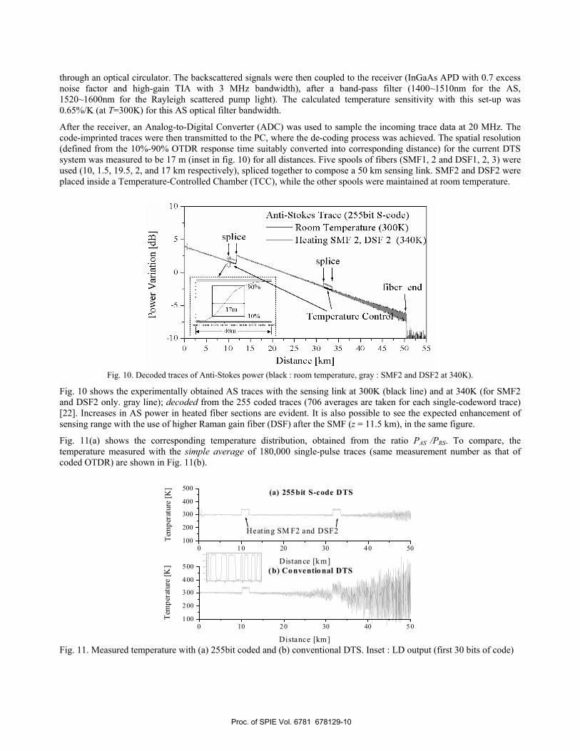
through an optical circulator. The backscattered signals were then coupled to the receiver (InGaAs APD with 0.7 excess noise factor and high-gain TIA with 3 MHz bandwidth), after a band-pass filter (1400~1510nm for the AS, 1520~1600nm for the Rayleigh scattered pump light). The calculated temperature sensitivity with this set-up was 0.65%/K (at T=300K) for this AS optical filter bandwidth.
After the receiver, an Analog-to-Digital Converter (ADC) was used to sample the incoming trace data at 20 MHz. The code-imprinted traces were then transmitted to the PC, where the de-coding process was achieved. The spatial resolution (defined from the 10%-90% OTDR response time suitably converted into corresponding distance) for the current DTS system was measured to be 17 m (inset in fig. 10) for all distances. Five spools of fibers (SMF1, 2 and DSF1, 2, 3) were used (10, 1.5, 19.5, 2, and 17 km respectively), spliced together to compose a 50 km sensing link. SMF2 and DSF2 were placed inside a Temperature-Controlled Chamber (TCC), while the other spools were maintained at room temperature.
Fig. 10. Decoded traces of Anti-Stokes power (black : room temperature, gray : SMF2 and DSF2 at 340K).
Fig. 10 shows the experimentally obtained AS traces with the sensing link at 300K (black line) and at 340K (for SMF2 and DSF2 only. gray line); decoded from the 255 coded traces (706 averages are taken for each single-codeword trace) [22]. Increases in AS power in heated fiber sections are evident. It is also possible to see the expected enhancement of sensing range with the use of higher Raman gain fiber (DSF) after the SMF (z = 11.5 km), in the same figure.
Fig. 11(a) shows the corresponding temperature distribution, obtained from the ratio PAS /PRS. To compare, the temperature measured with the simple average of 180,000 single-pulse traces (same measurement number as that of coded OTDR) are shown in Fig. 11(b).
Fig. 11. Measured temperature with (a) 255bit coded and (b) conventional DTS. Inset : LD output (first 30 bits of code)
0 10 20 30 40 50100
200
300
400
500 (b) Conventional DTS
Tem
pera
ture
[K]
Distance [km]
0 5 1 0 1 5 2 0 2 5 3 0
0
2 0
4 0
6 0
8 0
0 10 20 30 40 50100
200
300
400
500
Heating SM F2 and DSF2
(a) 255bit S-code DTS
Tem
pera
ture
[K]
Distance [k m]
Proc. of SPIE Vol. 6781 678129-10

Fig. 12. Temperature resolution vs distance for different code length (the spatial resolution is 17 m).
The root mean square temperature resolution (derived from RMS noise of the OTDR AS trace), plotted as a function of distance is shown in Fig. 12, for different code lengths (L = 1, 63, 255 bit) and fiber types (SMF, DSF, DCF). With a target temperature resolution of 3K, the sensing range was limited to 7.5 km for the conventional OTDR (L=1) with a SMF link. In contrast, with 255 bit code, it was possible to monitor the same temperature variation up to 33km (SMF + DSF link). Even greater increase in the sensing range (4km) was also possible, by replacing the DSF3 with a DCF (12 km, see Fig. 13), showing again good agreement with the theory (5.8km, for which the connector loss was ignored).
Fig. 13. Measured anti-Stokes trace (with DSF3 replaced to DCF)
4.4 Discussion
In summary, improved performance for Raman-based DTS systems is demonstrated, based on Simplex coding and link optimization techniques. An increase in the interrogation range (19.5km from the 255 bit coding, and 9.6km from link optimization) was measured with respect to conventional OTDR. At 3K / 17m temperature/spatial resolution, a total sensing range of 37km was obtained using conventional single-mode transmission fibers and low-power laser diode.
5. CONCLUSION
In this paper, we briefly outlined our contributions for the physical realization of coded OTDR, along with its principles and highlighting recent key results related with its applications. For the communication network application, we reported a multi-port / multi-wavelength, high-speed supervisory system for the in-service monitoring of a bidirectional WDM-PON system. The OTDR technique, based on most up-to-date technologies such as simplex coding, a tunable source, and optical switch, was applied to demonstrate a fast and reliable interrogation of the WDM-PON transmission line up to a
0 5 10 15 20 25 30 35 40 45 50 5502468
101214161820
4km5.6 km
DSF 3 (or DCF)SMF 1+2 DSF 1+2L = 1 (Conventional)L = 63L = 255L = 255 w/ DCF12km
RM
S Te
mpe
ratu
re R
esol
utio
n [K
]
Distance [km]
0 10 20 30 40 50-10
-5
0
5
10
4km5.6km
DCFDSFSMF
Anti-Stokes Trace (255bit S-code)
Pow
er V
aria
tion
[dB]
Distance [km]
Proc. of SPIE Vol. 6781 678129-11

16 port x 32 node (512 user) capacity. Monitoring of individual branch traces up to 60 km was achieved with the application of a 127-bit simplex code, corresponding to a 7.5dB SNR coding gain effectively reducing the measurement time about 30 times when compared to conventional OTDR. As an application to sensor network, a Raman scattering based coded-OTDR distributed temperature sensor system was presented. Utilizing a 255-bit Simplex coded OTDR together with optimized sensing link (composed of cascaded fibers with different Raman coefficients), significant enhancement in the interrogation distance was achieved to result a total sensing range of 37km (at 17m/3K spatial/temperature resolution), employing an off-shelf low power (80mW) laser diode. We believe that the coded OTDR could also be applied to various applications such as a TDM-PON systems and a Brillouin scattering based DTS.
REFERENCES
1 K. Okada, K. Hashimoto, T. Shibata, and Y. Nagaki, "Optical cable fault location using correlation technique," Electron. Lett., 16, 629-630, 1980. 2 A. S. Sudbo, "An optical time-domain reflectometer with low-power InGaAsP diode lasers," J. Lightwave Technol., LT-1, 616-618, 1983. 3 M. Nazarathy, S. A. Newton, R. P. Giffard, D. S. Moberly, F. Sischka, W. R. Trutna, Jr., and S. Foster, "Real-time long range complementary correlation optical time domain reflectometer," J. Lightwave Technol., 7, 24-38, 1989. 4 M. D. Jones, "Using simplex codes to improve OTDR sensitivity," IEEE Photon. Technol. Lett., 5, 822-824, 1993. 5 D. Lee, H. Yoon, P. Kim, J. Park, N. Y. Kim, and N. Park, “SNR Enhancement of OTDR Using Biorthogonal Codes and Generalized Inverses,” IEEE Photon. Technol. Lett., 17, 163-165, 2005. 6 D. Lee, H. Yoon, N. Y. Kim, H. Lee, and N. Park, “Analysis and experimental demonstration of simplex coding technique for SNR enhancement of OTDR”, LTIMC-15, Proceedings IEEE LTIMC, New York, October 2004. 7 P. Healey, "Review of long wavelength single-mode optical fiber reflectometry techniques," J. Lightwave Technol., LT-3, 876-886, 1985. 8 J. A. Decker, Jr., "Experimental realization of the multiplex advantage with a hadamard- transform spectrometer," Appl. Opt., 10, 510-514, 1971. 9 M. Harwit and N. J. Sloane, Hadamard transform optics. New York: Academic, 1979. 10 E. E. Fenimore and G. S. Weston, "Fast delta Hadamard transform," Appl. Opt., 20, 3058-3067, 1981. 11 K. S. Kim, “On the evolution of PON-based FTTH solutions,” Inform. Sci. 149, 21-30, 2003. 12 S. J. Park, C. H. Lee, K. T. Jeong, H. J. Park, J. G. Ahn, and K. H. Song, “Fiber-to-the-Home Services Based on Wavelength-Division-Multiplexing Passive Optical Network,” J. Lightwave Technol. 22, 2582-2591, 2004. 13 D. Derickson, Fiber Optic Test and Measurement (Prentice Hall PTR, Upper Saddle River, NJ, 1998), Chap. 11. 14 K. Tanaka, H. Izumita, N. Tomita and Y. Inoue, “In-service individual line monitoring and a method for compensating for the temperature-dependent channel drift of a WDM-PON containing an AWGR using a 1.6um tunable OTDR,” in European Conference on Optical Communications (ECOC’97), Paper 448, pp. 295-298. 15 U. Hilbk, M. Burmeister, B. Hoen, T. Hermes, J. Saniter, and F. J. Westphal, “Selective OTDR measurements at the central office of individual fiber link in a PON,” in Optical Fiber Communication Conference and Exhibit, Technical Digest (Optical Society of America, 1997), Paper Tuk3. 16 J. Lee, J. Park, J. G. Shim, H. Yoon, J. H. Kim, K. Kim, J.-O. Byun, and N. Park, “In-service monitoring of 16 port x 32 wavelength bi-directional WDM-PON systems with a tunable, coded optical time domain reflectometry,” Opt. Express, 15, 6874-6882, 2007 17 H. Izumita, S. Furukawa, Y. Koyamada, and I. Sankawa, “Fading noise reduction in coherent OTDR,” IEEE Photon. Technol. Lett. 4, 201–203, 1992. 18 J. P. Dakin et al., “Distributed optical fiber temperature sensor using a semiconductor light source and detector”, Electron. Lett., 21, 569-570, 1985. 19 M. A. Farahani et al., “Spontaneous Raman scattering in optical fibers with modulated probe light for distributed temperature Raman remote sensing”, J. Lightwave Technol., 17, 1379-1391, 1999. 20 H. H. Kee et al., “1.65mm Raman-based distributed temperature sensor”, Electron. Lett., 35, 1869-1870, 1999. 21 P.C. Wait et al., “A theoretical comparison of stimulated Raman and Brillouin based fibre optic distributed temperature sensors,” Opt. Comm., 144, 17-23, 1997. 22 G. Bolognini et al., “Performance Enhancement of Raman-based Distributed Temperature Sensors using Simplex Codes”, in OFC 2006 Tech. Dig., Mar.,2006, Paper OTuL1. 23 M.N. Islam, “Raman Amplifiers for Telecommunications”, 1, Springer Ed., 2004.
Proc. of SPIE Vol. 6781 678129-12