cmos switched-capacitor circuits for bio-medical and rf applications david j. allstot mackay...
TRANSCRIPT
CMOS Switched-Capacitor Circuits for Bio-Medical and RF Applications
David J. Allstot
Mackay Professor of EECS
University of California
Berkeley, CA 94720
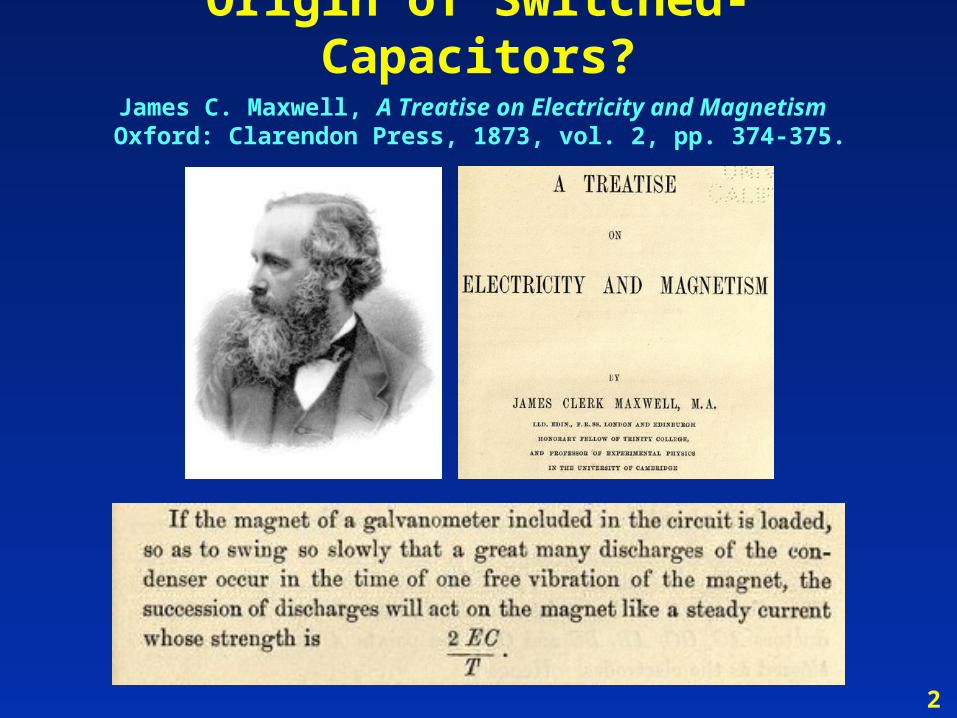
Origin of Switched-Capacitors?James C. Maxwell, A Treatise on Electricity and Magnetism
Oxford: Clarendon Press, 1873, vol. 2, pp. 374-375.
2
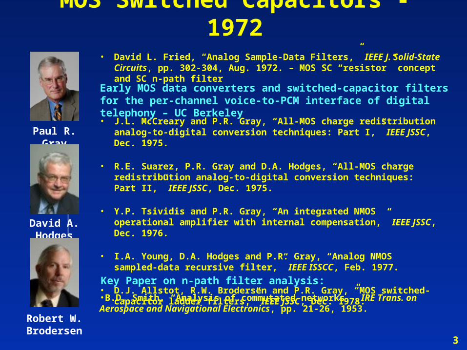
Paul R. Gray
David A. Hodges
Robert W. Brodersen
• J.L. McCreary and P.R. Gray, “All-MOS charge redistribution analog-to-digital conversion techniques: Part I,” IEEE JSSC, Dec. 1975.
• R.E. Suarez, P.R. Gray and D.A. Hodges, “All-MOS charge redistribution analog-to-digital conversion techniques: Part II,” IEEE JSSC, Dec. 1975.
• Y.P. Tsividis and P.R. Gray, “An integrated NMOS operational amplifier with internal compensation,” IEEE JSSC, Dec. 1976.
• I.A. Young, D.A. Hodges and P.R. Gray, “Analog NMOS sampled-data recursive filter,” IEEE ISSCC, Feb. 1977.
• D.J. Allstot, R.W. Brodersen and P.R. Gray, “MOS switched-capacitor ladder filters,” IEEE JSSC, Dec. 1978.
3
MOS Switched Capacitors - 1972• David L. Fried, “Analog Sample-Data Filters,” IEEE J. Solid-State Circuits,
pp. 302-304, Aug. 1972. – MOS SC “resistor” concept and SC n-path filter
Early MOS data converters and switched-capacitor filters for the per-channel voice-to-PCM interface of digital telephony – UC Berkeley
Key Paper on n-path filter analysis:
•B.D. Smith, “Analysis of commutated networks,” IRE Trans. on Aerospace and Navigational Electronics, pp. 21-26, 1953.
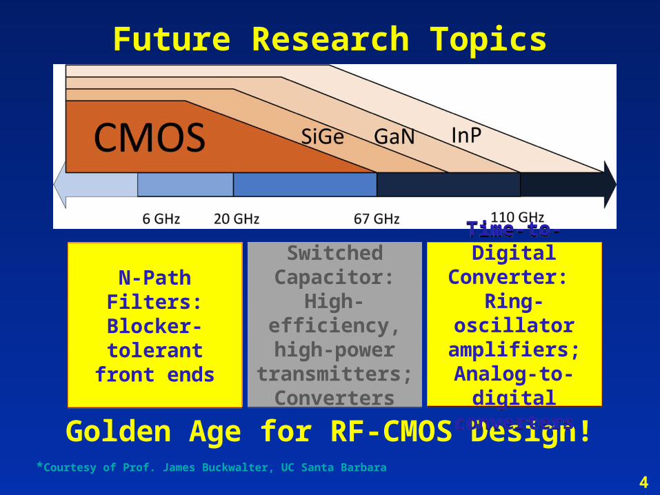
Future Research Topics
Golden Age for RF-CMOS Design!*Courtesy of Prof. James Buckwalter, UC Santa Barbara
Switched Capacitor:
High-efficiency, high-power
transmitters;Converters
Switched Capacitor:
High-efficiency, high-power
transmitters;Converters
N-Path Filters: Blocker-tolerant
front ends
N-Path Filters: Blocker-tolerant
front ends
Time-to-Digital Converter:
Ring-oscillator amplifiers;
Analog-to-digital converters
Time-to-Digital Converter:
Ring-oscillator amplifiers;
Analog-to-digital converters
4
Outline
Challenges in CMOS Radio Design
Switched-Capacitor N-path Filters
Analog-domain Compressed Sensing for
Bio-signal Acquisition
5
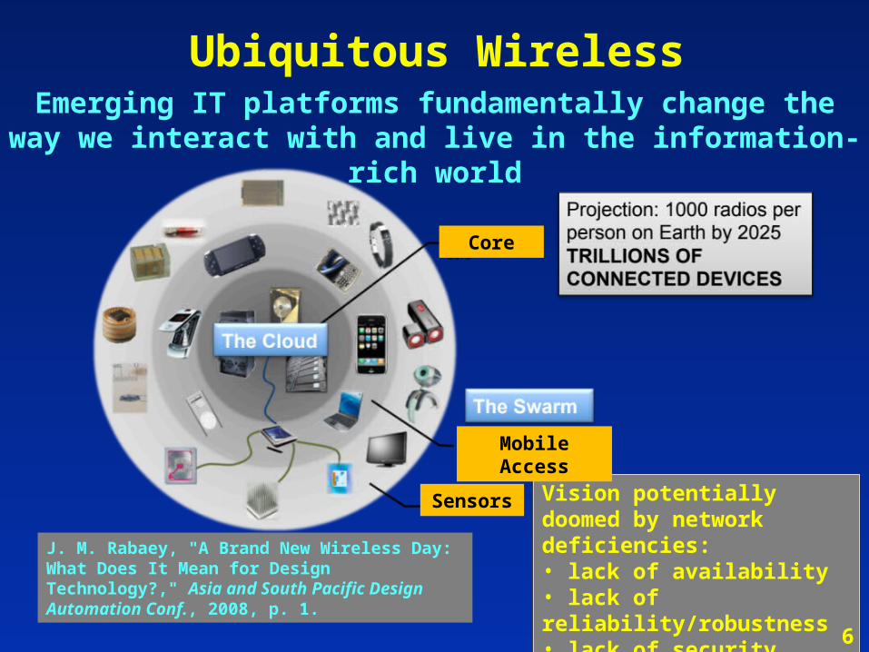
Emerging IT platforms fundamentally change the way we interact with and live in the information-rich world
Ubiquitous Wireless
Vision potentially doomed by network deficiencies:• lack of availability• lack of reliability/robustness• lack of security
Vision potentially doomed by network deficiencies:• lack of availability• lack of reliability/robustness• lack of security
J. M. Rabaey, "A Brand New Wireless Day: What Does It Mean for Design Technology?," Asia and South Pacific Design Automation Conf., 2008, p. 1.
Sensors
Mobile Access
Core
6
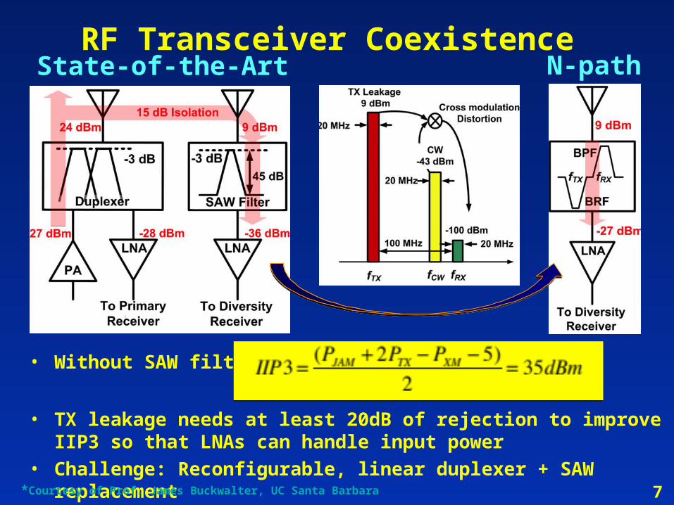
• Without SAW filter:
• TX leakage needs at least 20dB of rejection to improve IIP3 so that LNAs can handle input power
• Challenge: Reconfigurable, linear duplexer + SAW replacement
State-of-the-Art N-pathRF Transceiver Coexistence
7*Courtesy of Prof. James Buckwalter, UC Santa Barbara
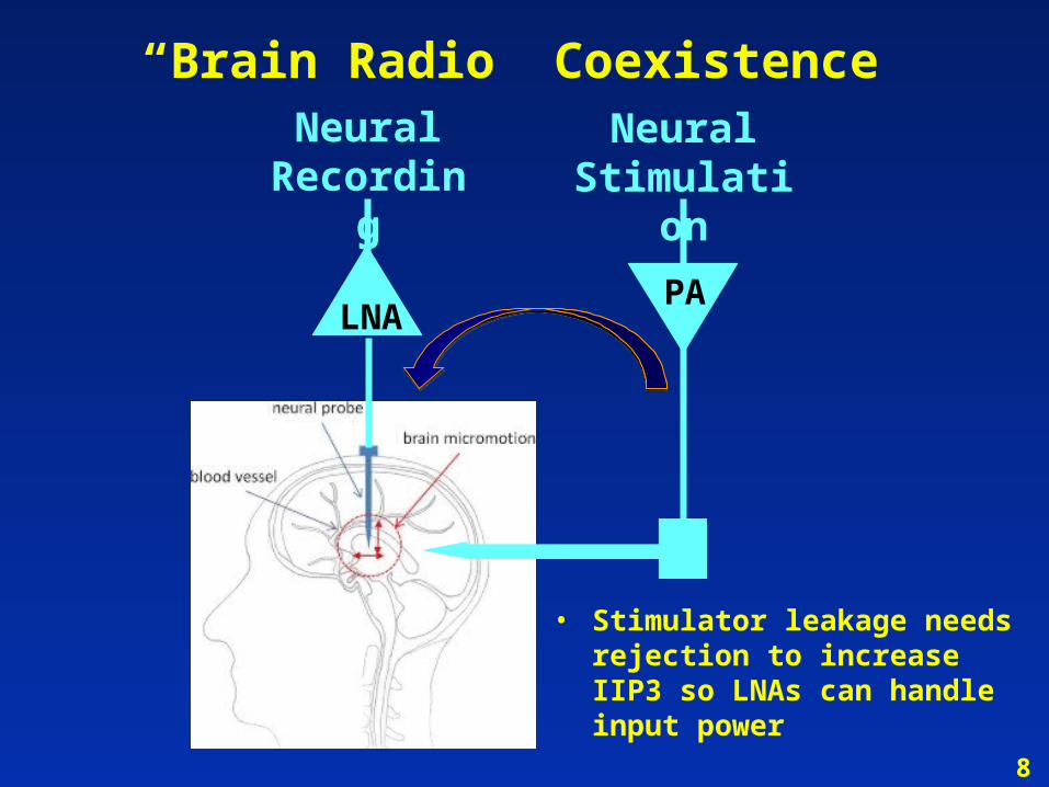
“Brain Radio” Coexistence
8
LNAPA
Neural Recording
Neural Stimulation
• Stimulator leakage needs rejection to increase IIP3 so LNAs can handle input power
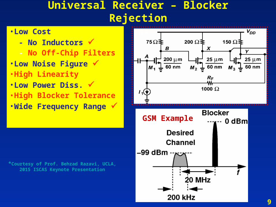
Universal Receiver – Blocker Rejection• Low Cost - No Inductors - No Off-Chip Filters• Low Noise Figure• High Linearity• Low Power Diss. • High Blocker Tolerance• Wide Frequency Range
• Low Cost
- No Inductors - No Off-Chip Filters• Low Noise Figure • High Linearity• Low Power Diss. • High Blocker Tolerance• Wide Frequency Range GSM Example
*Courtesy of Prof. Behzad Razavi, UCLA, 2015 ISCAS Keynote Presentation
9
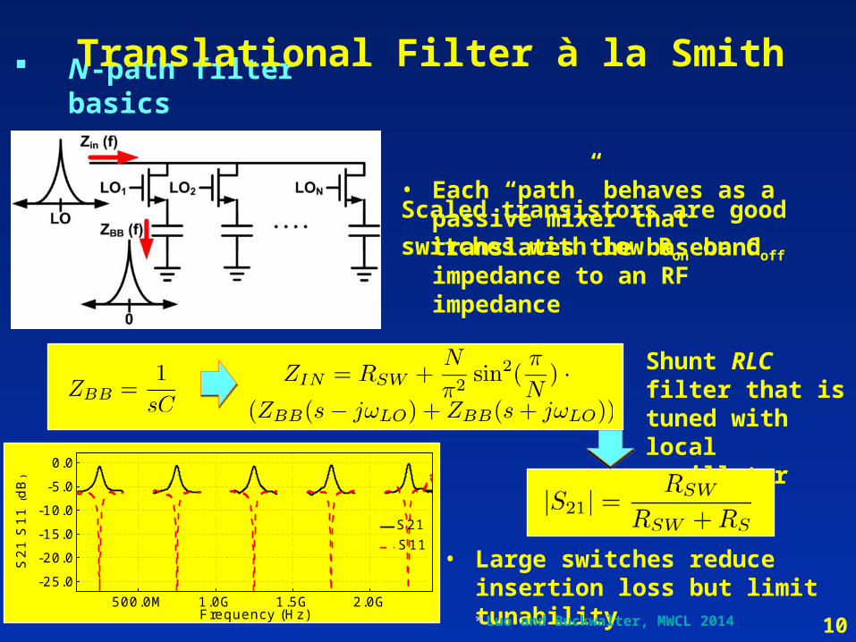
N-path filter basics
• Scaled transistors are good
switches with low Ron on Coff
500.0M 1.0G 1.5G 2.0G-25.0
-20.0
-15.0
-10.0
-5.0
0.0
Frequency (Hz)
S21 S11
S21
S11
(dB
)
Shunt RLC filter that is tuned with local oscillator
• Each “path” behaves as a passive mixer that translates the baseband impedance to an RF impedance
• Large switches reduce insertion loss but limit tunability* Luo and Buckwalter, MWCL 2014
Translational Filter à la Smith
10
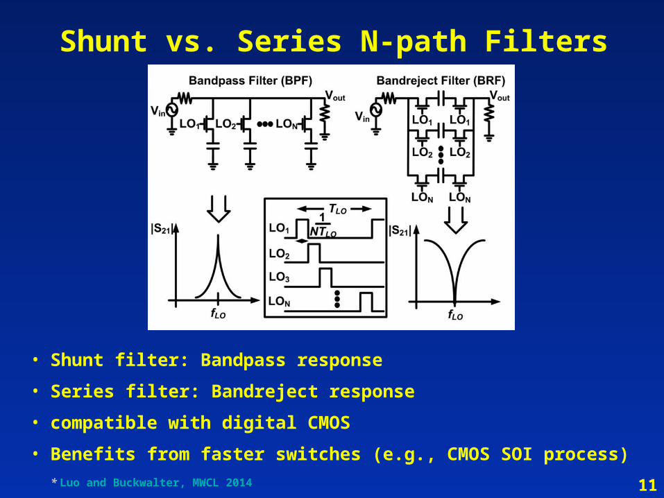
• Shunt filter: Bandpass response
• Series filter: Bandreject response
• compatible with digital CMOS
• Benefits from faster switches (e.g., CMOS SOI process)
Shunt vs. Series N-path Filters
* Luo and Buckwalter, MWCL 2014 11
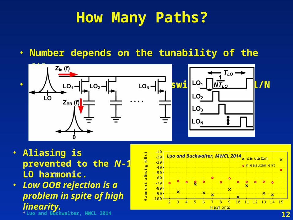
How Many Paths?
• Number depends on the tunability of the filter
• Require each path to be switched with 1/N duty cycle
2 3 4 5 6 7 8 9 10 11 12 13 14 15-100-90-80-70-60-50-40-30-20-10
Har
mon
ic a
liasi
ng (
dBc)
Harmonic
simulation
measurement
• Aliasing is prevented to the N-1 LO harmonic.
• Low OOB rejection is a problem in spite of high linearity.
Luo and Buckwalter, MWCL 2014
* Luo and Buckwalter, MWCL 2014 12

N-path filter basics
Can We Filter at the Antenna?
• For BW = 200 kHz: Ctot = 28 nF• For 20-dB rejection: Rsw = 5 • Switch linearity with 0-dBm blocker?
*Courtesy of Prof. Behzad Razavi, UCLA, 2015 ISCAS Keynote Presentation13
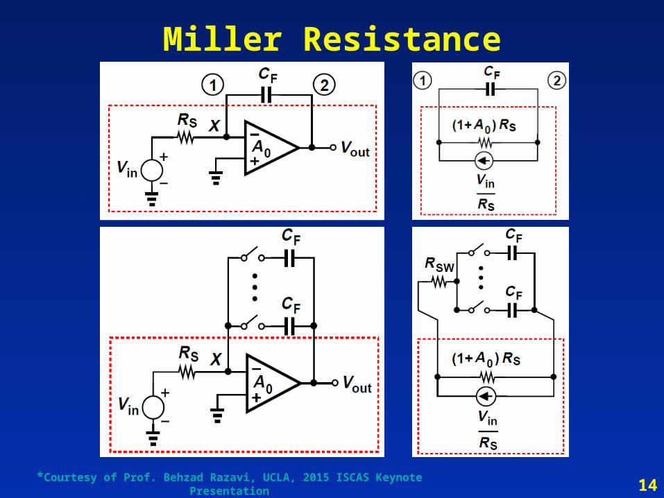
Miller Resistance
14*Courtesy of Prof. Behzad Razavi, UCLA, 2015 ISCAS Keynote Presentation
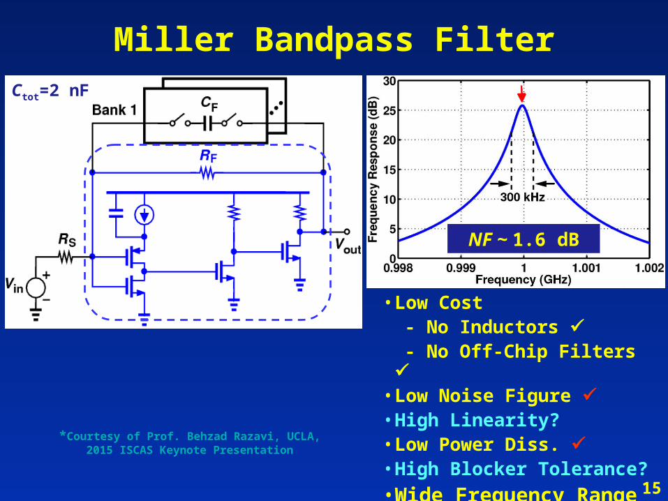
Miller Bandpass FilterCtot=2 nF
NF ~ 1.6 dB
• Low Cost - No Inductors - No Off-Chip Filters • Low Noise Figure • High Linearity?• Low Power Diss. • High Blocker Tolerance?
• Wide Frequency Range 15
*Courtesy of Prof. Behzad Razavi, UCLA, 2015 ISCAS Keynote Presentation
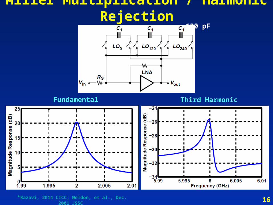
Miller Multiplication / Harmonic Rejection
Fundamental Third Harmonic
50
100 pF
16*Razavi, 2014 CICC; Weldon, et al., Dec. 2001 JSSC
Outline for Compressed Sensing
Motivation for Compressive Sampling
Intuition and Key Ideas
Reconstruction
Experimental Results
17
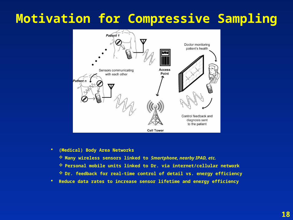
Motivation for Compressive Sampling
(Medical) Body Area Networks
Many wireless sensors linked to Smartphone, nearby IPAD, etc.
Personal mobile units linked to Dr. via internet/cellular network
Dr. feedback for real-time control of detail vs. energy efficiency
Reduce data rates to increase sensor lifetime and energy efficiency
18

CS Sensor System
Ultra-low-power CS Analog Front-end
RF PA is Dominant Energy Consumer; ADC Next
CS Compresses Data Rate and PA/ADC Duty Cycles
Compressed Data [Y] is Digitized and Transmitted
LNA ADCPower
Amplifier
Antenna
CS AFEElectrode
Compressed Sampling Bio-Signal Acquisition System
Sensor
x(t) [Y]
Compressed Data RateFeedback
19
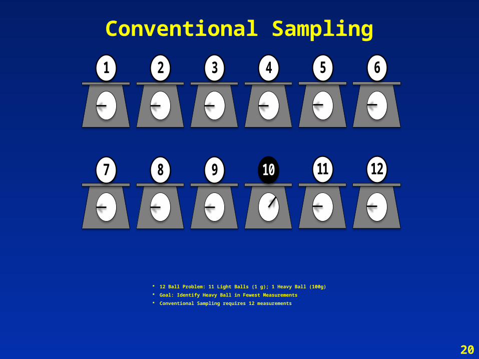
Conventional Sampling
1 2 3 4 5 6
7 8 9 11 1210
12 Ball Problem: 11 Light Balls (1 g); 1 Heavy Ball (100g)
Goal: Identify Heavy Ball in Fewest Measurements
Conventional Sampling requires 12 measurements
20
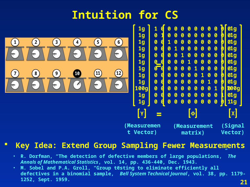
Intuition for CS
Key Idea: Extend Group Sampling Fewer Measurements• R. Dorfman, “The detection of defective members of large populations,” The Annals of
Mathematical Statistics, vol. 14, pp. 436-440, Dec. 1943.• M. Sobel and P.A. Groll, “Group testing to eliminate efficiently all defectives in a binomial sample,”
Bell System Technical Journal, vol. 38, pp. 1179-1252, Sept. 1959.
1 2 3 4 5 6
7 8 9 11 1210
1g1g1g1g1g1g1g1g1g
100g1g1g
1 0 0 0 0 0 0 0 0 0 0 0 0 1 0 0 0 0 0 0 0 0 0 00 0 1 0 0 0 0 0 0 0 0 00 0 0 1 0 0 0 0 0 0 0 00 0 0 0 1 0 0 0 0 0 0 00 0 0 0 0 1 0 0 0 0 0 00 0 0 0 0 0 1 0 0 0 0 00 0 0 0 0 0 0 1 0 0 0 00 0 0 0 0 0 0 0 1 0 0 00 0 0 0 0 0 0 0 0 1 0 00 0 0 0 0 0 0 0 0 0 1 00 0 0 0 0 0 0 0 0 0 0 1
1g1g1g1g1g1g1g1g1g
100g1g1g
=
Y = X
(Measurement Vector)
(Measurementmatrix)
(Signal Vector)
21
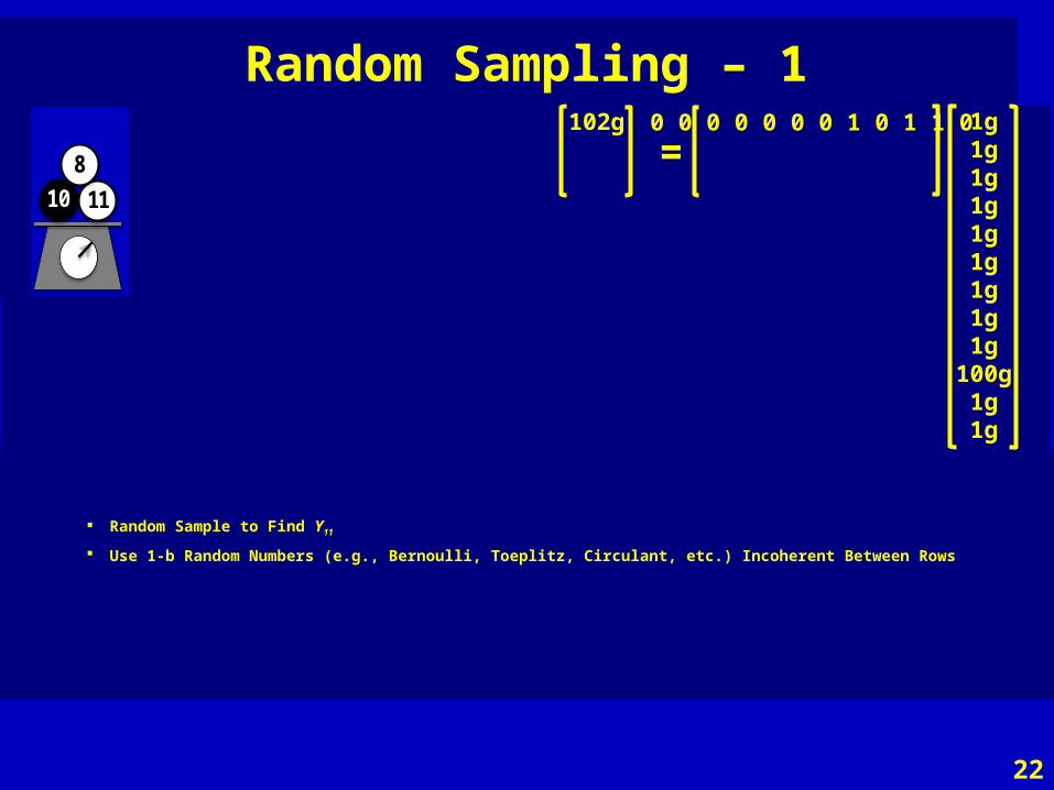
Random Sampling – 1
7 116
1 5
2 811
8
10
3 4
129
1
10
102g 0 0 0 0 0 0 0 1 0 1 1 0 1g1g1g1g1g1g1g1g1g
100g1g1g
=
Random Sample to Find Y11
Use 1-b Random Numbers (e.g., Bernoulli, Toeplitz, Circulant, etc.) Incoherent Between Rows
22

Random Sampling – 2
7 116
1 5
2 811
8
10
3 4
129
1
10
7 116
1 5
2 811
8
10
3 4
129
1
10
102g5g
0 0 0 0 0 0 0 1 0 1 1 0 1 0 0 0 1 1 1 0 0 0 1 0
1g1g1g1g1g1g1g1g1g
100g1g1g
=
23
Random Sample to Find Y21
Use 1-b Random Numbers (e.g., Bernoulli, Toeplitz, Circulant, etc.) Incoherent Between Rows

Random Sampling – 3
7 116
1 5
2 811
8
10
3 4
129
1
10
7 116
1 5
2 811
8
10
3 4
129
1
10
102g5g
105g
0 0 0 0 0 0 0 1 0 1 1 0 1 0 0 0 1 1 1 0 0 0 1 0 1 0 1 1 0 0 0 0 1 1 0 1
1g1g1g1g1g1g1g1g1g
100g1g1g
=
7 116
1 5
2 811
8
10
3 4
129
1
10
Random Sample to Find Y31
Reconstruction: Two Heavy Measurements—Only #10 Common
Fewer Measurements (e.g., 3)
CS Works for Sparse Signals
Other (unlikely) Possibilities:
Solution in 1 Measurement
No Solution in M Measurements
24
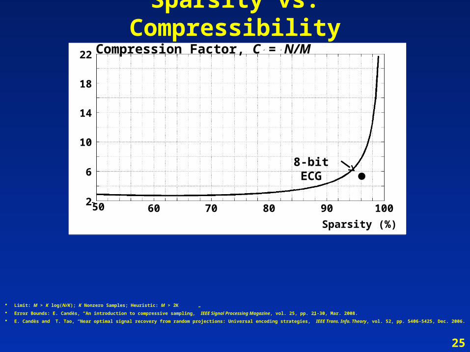
Sparsity vs. Compressibility
Limit: M > K log(N/K); K Nonzero Samples; Heuristic: M > 2K
Error Bounds: E. Candès, “An introduction to compressive sampling,” IEEE Signal Processing Magazine, vol. 25, pp. 21-30, Mar. 2008.
E. Candès and T. Tao, “Near optimal signal recovery from random projections: Universal encoding strategies,” IEEE Trans. Info. Theory, vol. 52, pp. 5406-5425, Dec. 2006.
50 60 70 80 90 100
Sparsity (%)
2
6
10
14
18
22 Compression Factor, C = N/M
8-bit ECG
25
26
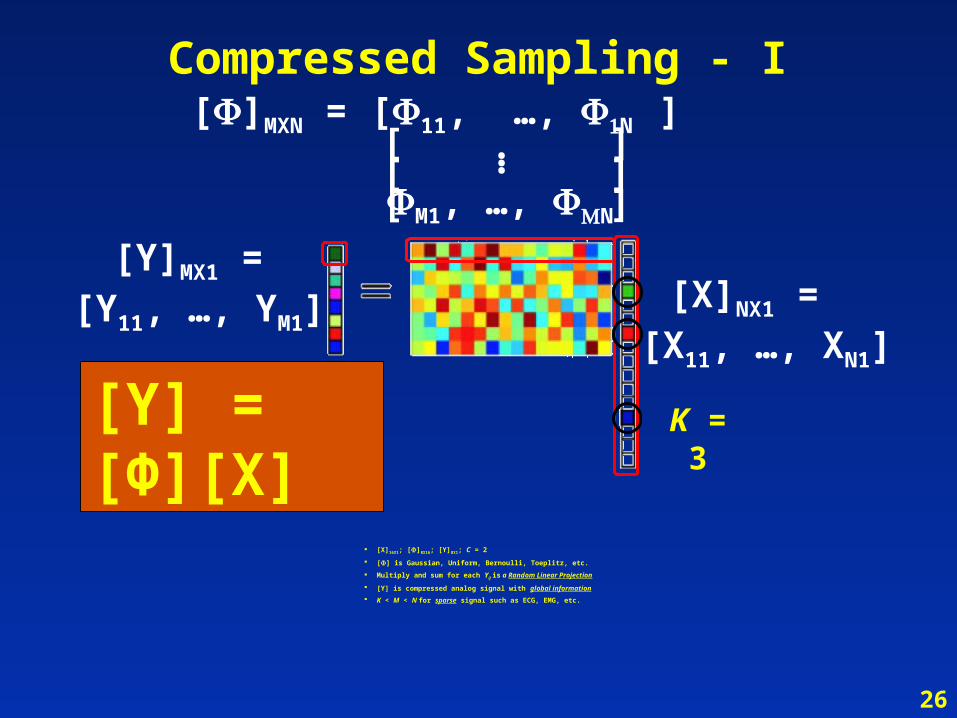
Compressed Sampling - I
[X]NX1 = [X11, …, XN1]
[Y]MX1 = [Y11, …, YM1]
[X]16X1; []8X16; [Y]8X1; C = 2
[] is Gaussian, Uniform, Bernoulli, Toeplitz, etc.
Multiply and sum for each Yij is a Random Linear Projection
[Y] is compressed analog signal with global information
K < M < N for sparse signal such as ECG, EMG, etc.
[]MXN = [11, …, N ][[[
]]]M1, …, N
…K = 3[Y] = [Φ][X]
27
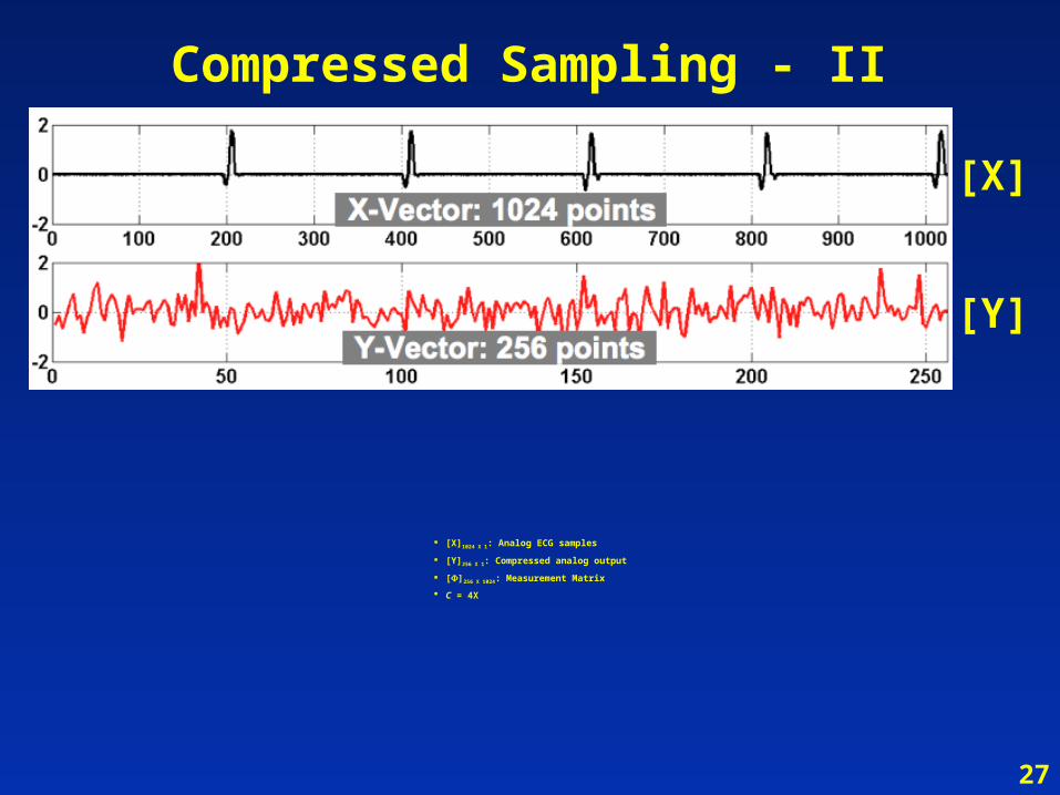
Compressed Sampling - II
[X]1024 X 1: Analog ECG samples
[Y]256 X 1: Compressed analog output
[]256 X 1024: Measurement Matrix
C = 4X
[X]
[Y]
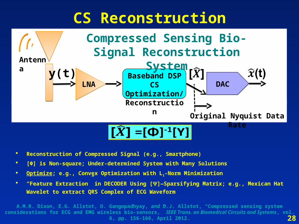
CS Reconstruction
Reconstruction of Compressed Signal (e.g., Smartphone)
[Φ] is Non-square; Under-determined System with Many Solutions
Optimize; e.g., Convex Optimization with L1-Norm Minimization
“Feature Extraction” in DECODER Using []—Sparsifying Matrix; e.g., Mexican Hat Wavelet to extract
QRS Complex of ECG Waveform
LNA DAC
Antenna
Baseband DSPCS Optimization/ Reconstruction
Compressed Sensing Bio-Signal Reconstruction System
y(t)
Original Nyquist Data Rate
28
A.M.R. Dixon, E.G. Allstot, D. Gangopadhyay, and D.J. Allstot, “Compressed sensing system considerations for ECG and EMG wireless bio-sensors,” IEEE Trans. on Biomedical Circuits and Systems, vol. 6, pp. 156-166, April 2012.

29
CS Reconstruction - II
Accuracy depends on:
Compression Factor, C = N/M
PDF of random coefficients and # bits
Algorithm—Convex Optimization with L1 Norm
[X]
[Y]
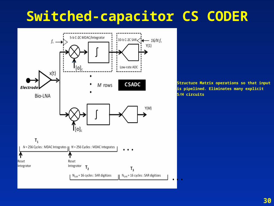
Switched-capacitor CS CODER
Structure Matrix operations so that input is
pipelined. Eliminates many explicit S/H circuitsElectrode
CSADC
CSADC
30
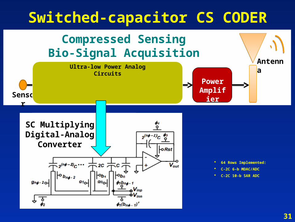
Switched-capacitor CS CODER
64 Rows Implemented:
C-2C 6-b MDAC/ADC
C-2C 10-b SAR ADC
[Y] = [Φ][X]LNA ADC Power
Amplifier
Antenna
CS AFEElectrode
Compressed Sensing Bio-Signal Acquisition System
Sensor
Ultra-low Power Analog Circuits
SC Multiplying Digital-Analog
Converter
31

Switched-capacitor CS CODER
64 Rows digitally selectable
N is programmable
Fig. 3. CSADC circuits. Counterclockwise from top: Opamp, C-2C MDAC/integrator, C-2C SAR ADC (withpre-amp offset cancellation), and comparator. Device stacking to reduce W/L and dual-gate switchesand logic gates are used to minimize leakage.
32
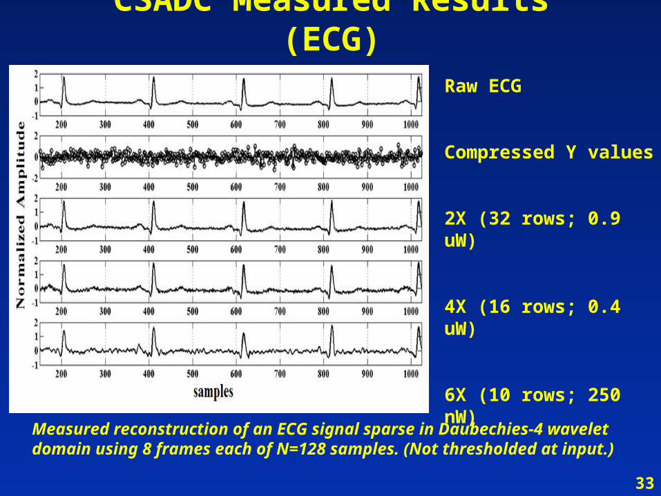
CSADC Measured Results (ECG)Raw ECG
Compressed Y values
2X (32 rows; 0.9 uW)
4X (16 rows; 0.4 uW)
6X (10 rows; 250 nW)
Measured reconstruction of an ECG signal sparse in Daubechies-4 wavelet domain using 8 frames each of N=128 samples. (Not thresholded at input.)
33
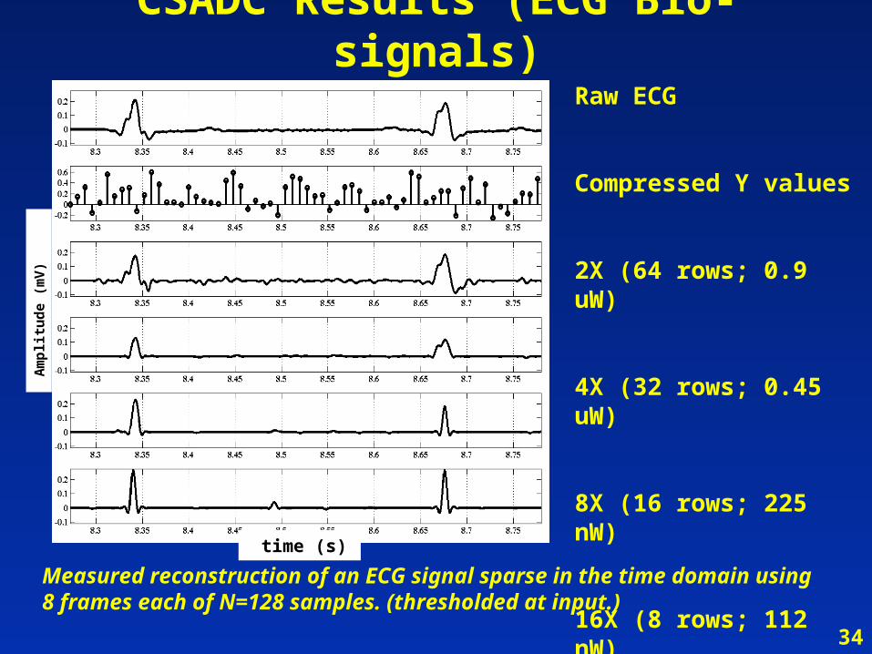
CSADC Results (ECG Bio-signals)
time (s)
Am
pli
tud
e (m
V)
Raw ECG
Compressed Y values
2X (64 rows; 0.9 uW)
4X (32 rows; 0.45 uW)
8X (16 rows; 225 nW)
16X (8 rows; 112 nW)
Measured reconstruction of an ECG signal sparse in the time domain using 8 frames each of N=128 samples. (thresholded at input.)
34
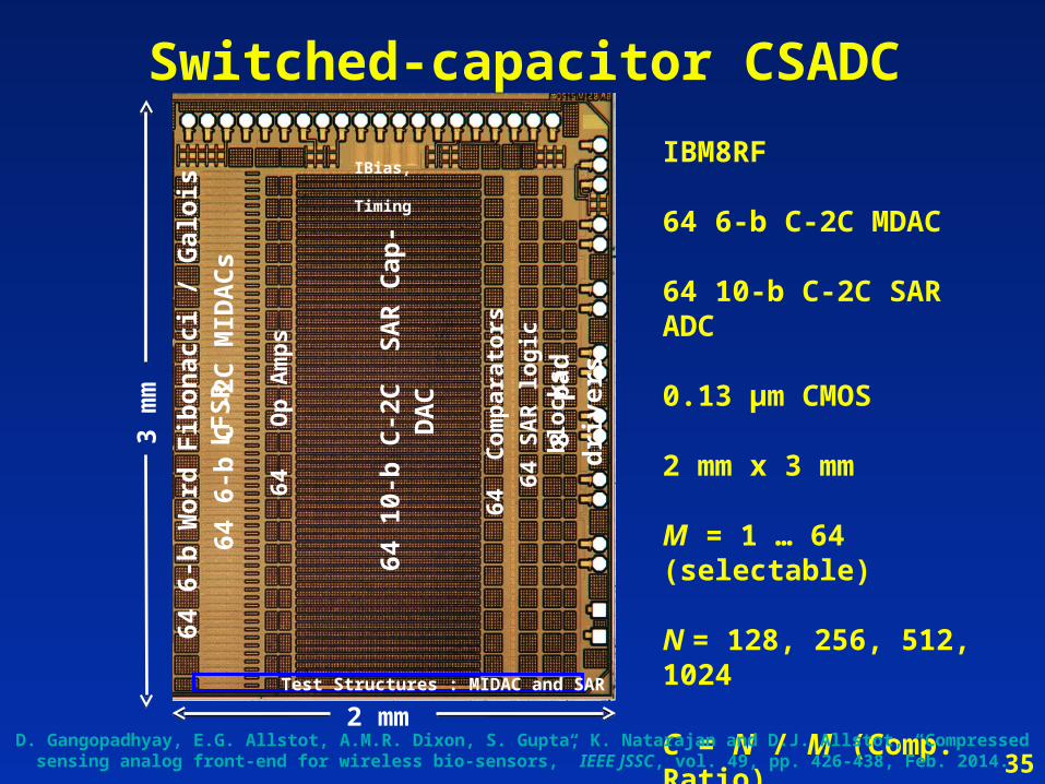
Switched-capacitor CSADC
IBM8RF
64 6-b C-2C MDAC
64 10-b C-2C SAR ADC 0.13 µm CMOS
2 mm x 3 mm
M = 1 … 64 (selectable)
N = 128, 256, 512, 1024
C = N / M (Comp. Ratio)
28 nW/row
3 m
m
2 mm
64
6-b
C -
2C M
IDA
Cs
IBias, Timing
64
10-b
C-2
C
SA
R C
ap-D
AC
8
pad
dri
vers
64
SA
R lo
gic
blo
cks
64 C
om
par
ato
rs
Test Structures : MIDAC and SAR
64
Op
Am
ps
64
6-b
Wo
rd F
ibo
nac
ci /
Gal
ois
LF
SR
35D. Gangopadhyay, E.G. Allstot, A.M.R. Dixon, S. Gupta, K. Natarajan and D.J. Allstot, “Compressed sensing analog front-
end for wireless bio-sensors,” IEEE JSSC, vol. 49, pp. 426-438, Feb. 2014.
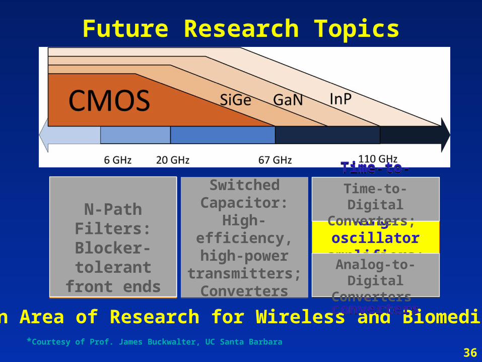
Future Research Topics
Open Area of Research for Wireless and Biomedical!*Courtesy of Prof. James Buckwalter, UC Santa Barbara
Switched Capacitor:
High-efficiency, high-power
transmitters;Converters
Switched Capacitor:
High-efficiency, high-power
transmitters;Converters
Time-to-Digital Converter:
Ring-oscillator amplifiers;
Analog-to-digital converters
Time-to-Digital Converter:
Ring-oscillator amplifiers;
Analog-to-digital converters
36
N-Path Filters: Blocker-
tolerant front ends
Time-to-Digital Converters;
Analog-to-Digital Converters
Mulţumesc
37