clustering & nlb
TRANSCRIPT
Clustering TechnologiesUpdated: March 28, 2003
Clustering Technologies
The clustering technologies in products in the Microsoft Windows Server 2003 operating system are
designed to help you achieve high availability and scalability for applications that are critically
important to your business. These applications include corporate databases, e-mail, and Web-based
services such as retail Web sites. By using appropriate clustering technologies and carefully
implementing good design and operational practices (for example, configuration management and
capacity management), you can scale your installation appropriately and ensure that your applications
and services are available whenever customers and employees need them.
High availability is the ability to provide user access to a service or application for a high percentage of
scheduled time by attempting to reduce unscheduled outages and mitigate the impact of scheduled
downtime for particular servers. Scalability is the ability to easily increase or decrease computing
capacity. A cluster consists of two or more computers working together to provide a higher level of
availability, scalability, or both than can be obtained by using a single computer. Availability is
increased in a cluster because a failure in one computer results in the workload being redistributed to
another computer. Scalability tends to be increased, because in many situations it is easy to change
the number of computers in the cluster.
Windows Server 2003 provides two clustering technologies: server clusters and Network Load
Balancing (NLB). Server clusters primarily provide high availability; Network Load Balancing provides
scalability and at the same time helps increase availability of Web-based services.
Your choice of cluster technologies (server clusters or Network Load Balancing) depends primarily on
whether the applications you run have long-running in-memory state:
Server clusters are designed for applications that have long-running in-memory state or
frequently updated data. These are called stateful applications. Examples of stateful
applications include database applications such as Microsoft SQL Server 2000 and messaging
applications such as Microsoft Exchange Server 2003.
Server clusters can combine up to eight servers.
Network Load Balancing is intended for applications that do not have long-running in-
memory state. These are called stateless applications. A stateless application treats each
client request as an independent operation, and therefore it can load-balance each request
independently. Stateless applications often have read-only data or data that changes
infrequently. Web front-end servers, virtual private networks (VPNs), and File Transfer
Protocol (FTP) servers typically use Network Load Balancing. Network Load Balancing clusters
can also support other TCP- or UDP-based services and applications.
Network Load Balancing can combine up to 32 servers.
In addition, with Microsoft Application Center 2000 Service Pack 2, you can create another type of
cluster, a Component Load Balancing cluster. Component Load Balancing clusters balance the load
between Web-based applications distributed across multiple servers and simplify the management of
those applications. Application Center 2000 Service Pack 2 can be used with Web applications built on
either the Microsoft Windows 2000 or Windows Server 2003 operating systems.
Multitiered Approach for Deployment of Multiple Clustering Technologies
Microsoft does not support the configuration of server clusters and Network Load Balancing clusters on
the same server. Instead, use these technologies in a multitiered approach.
Clustering Technologies Architecture
A cluster consists of two or more computers (servers) working together. For server clusters, the
individual servers are called nodes. For Network Load Balancing clusters, the individual servers are
called hosts.
Basic Architecture for Server Clusters
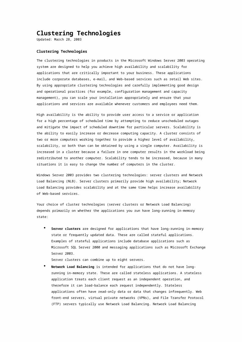
The following diagram shows a four-node server cluster of the most common type, called a single
quorum device cluster. In this type of server cluster, there are multiple nodes with one or more cluster
disk arrays (often called the cluster storage) and a connection device (bus). Each of the disks in the
disk array are owned and managed by only one node at a time. The quorum resource on the cluster
disk array provides node-independent storage for cluster configuration and state data, so that each
node can obtain that data even if one or more other nodes are down.
Four-Node Server Cluster Using a Single Quorum Device
Basic Architecture for Network Load Balancing Clusters
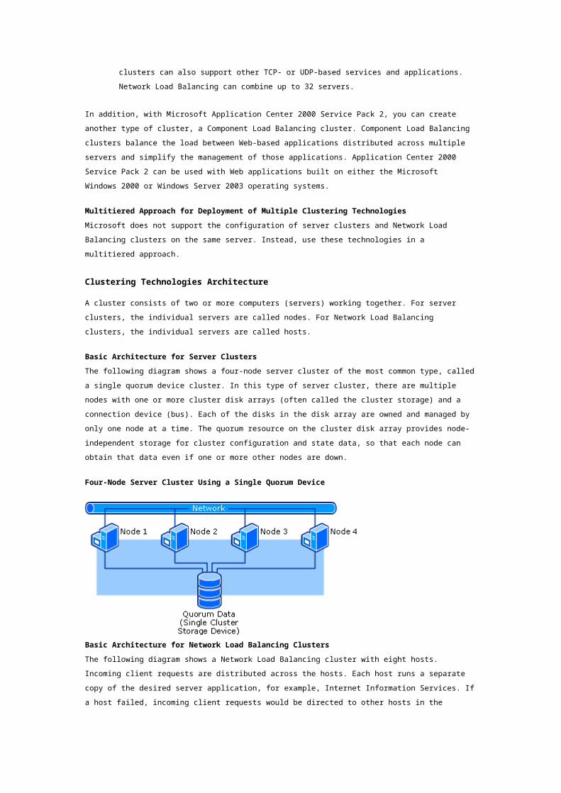
The following diagram shows a Network Load Balancing cluster with eight hosts. Incoming client
requests are distributed across the hosts. Each host runs a separate copy of the desired server
application, for example, Internet Information Services. If a host failed, incoming client requests would
be directed to other hosts in the cluster. If the load increased and additional hosts were needed, you
could add them dynamically to the cluster.
Network Load Balancing Cluster with Eight Hosts
Clustering Technologies Scenarios
This section describes the most common scenarios for using server clusters and Network Load
Balancing.
Scenarios for Server Clusters
This section provides brief descriptions of some of the scenarios for server cluster deployment. The
scenarios cover three different aspects of server cluster deployment:
The applications or services on the server cluster.
The type of storage option: SCSI, Fibre Channel arbitrated loops, or Fibre Channel switched
fabric.
The number of nodes and the ways that the nodes can fail over to each other.
Applications or Services on a Server Cluster
Server clusters are usually used for services, applications, or other resources that need high
availability. Some of the most common resources deployed on a server cluster include:
Printing
File sharing
Network infrastructure services. These include the DHCP service and the WINS service.
Services that support transaction processing and distributed applications. These
services include the Distributed Transaction Coordinator (DTC) and Message Queuing.
Messaging applications. An example of a messaging application is Microsoft Exchange
Server 2003.
Database applications. An example of a database application is Microsoft SQL Server 2000.
Types of Storage Options
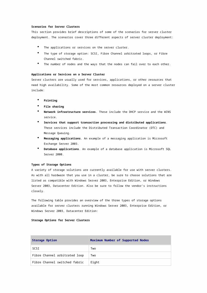
A variety of storage solutions are currently available for use with server clusters. As with all hardware
that you use in a cluster, be sure to choose solutions that are listed as compatible with Windows
Server 2003, Enterprise Edition, or Windows Server 2003, Datacenter Edition. Also be sure to follow
the vendor’s instructions closely.
The following table provides an overview of the three types of storage options available for server
clusters running Windows Server 2003, Enterprise Edition, or Windows Server 2003, Datacenter
Edition:
Storage Options for Server Clusters
Storage Option Maximum Number of Supported Nodes
SCSI Two
Fibre Channel arbitrated loop Two
Fibre Channel switched fabric Eight
Number of Nodes and Failover Plan
Another aspect of server cluster design is the number of nodes used and the plan for application
failover:
N-node Failover Pairs. In this mode of operation, each application is set to fail over
between two specified nodes.
Hot-Standby Server /N+I. Hot-standby server operation mode reduces the overhead of
failover pairs by consolidating the “spare” (idle) node for each pair into a single node,
providing a server that is capable of running the applications from each node pair in the event
of a failure. This mode of operation is also referred to as active/passive.
For larger clusters, N+I mode provides an extension of the hot-standby server mode where N
cluster nodes host applications and I cluster nodes are spare nodes.
Failover Ring. In this mode of operation, each node in the cluster runs an application
instance. In the event of a failure, the application on the failed node is moved to the next
node in sequence.
Random. For large clusters running multiple applications, the best policy in some cases is to
allow the server cluster to choose the fail over node at random.
Scenarios for Network Load Balancing
This section provides brief descriptions of some of the scenarios for deployment of Network Load
Balancing. The scenarios cover three different aspects of Network Load Balancing deployment:
The types of servers or services in Network Load Balancing clusters.
The number and mode of network adapters on each host.
Types of Servers or Services in Network Load Balancing Clusters
In Network Load Balancing clusters, some of the most common types of servers or services are as
follows:
Web and File Transfer Protocol (FTP) servers.
ISA servers (for proxy servers and firewall services).
Virtual private network (VPN) servers.
Windows Media servers.
Terminal servers.
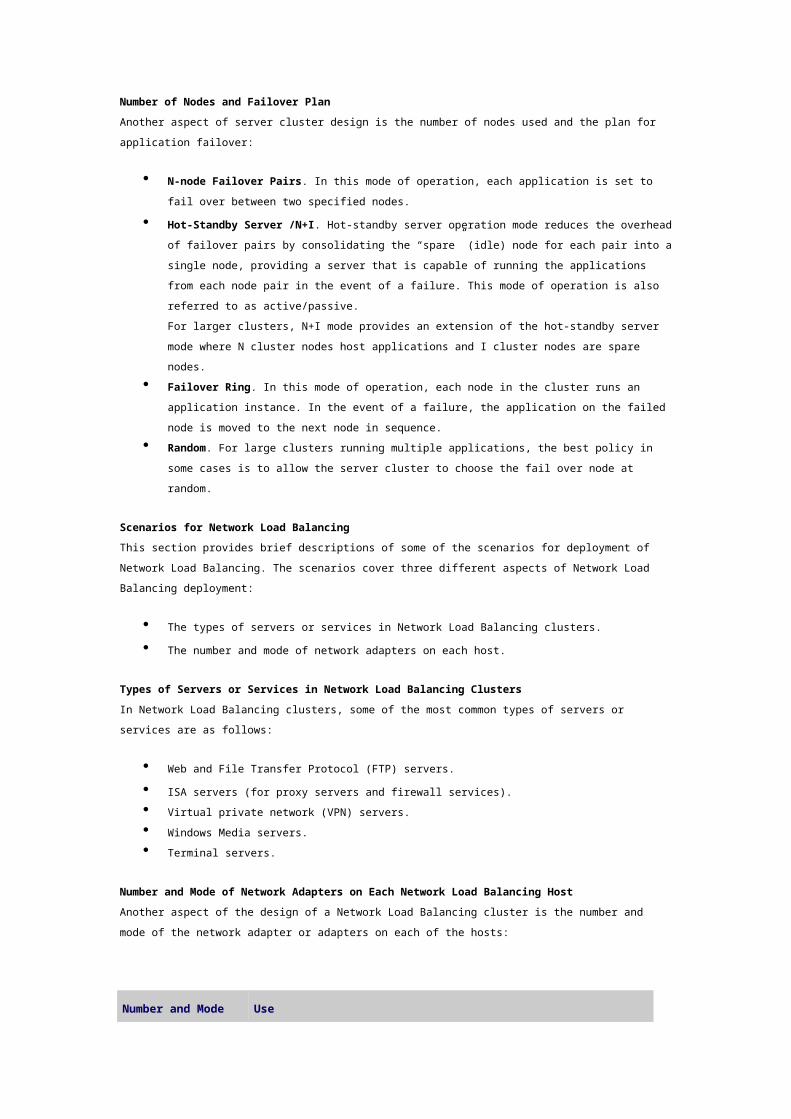
Number and Mode of Network Adapters on Each Network Load Balancing Host
Another aspect of the design of a Network Load Balancing cluster is the number and mode of the
network adapter or adapters on each of the hosts:
Number and Mode of Network Adapters on Each Host Use
Single network adapter in unicast mode
A cluster in which ordinary network communication among cluster hosts is not required and in which there is limited dedicated traffic from outside the cluster subnet to specific cluster hosts.
Multiple network adapters in unicast mode
A cluster in which ordinary network communication among cluster hosts is necessary or desirable. It is also appropriate when you want to separate the traffic used to manage the cluster from the traffic occurring between the cluster and client computers.
Single network adapter in multicast mode
A cluster in which ordinary network communication among cluster hosts is necessary or desirable but in which there is limited dedicated traffic from outside the cluster subnet to specific cluster hosts.
Multiple network adapters in multicast mode
A cluster in which ordinary network communication among cluster hosts is necessary and in which there is heavy dedicated traffic from outside the cluster subnet to specific cluster hosts.
Server Clusters Technical ReferenceUpdated: March 28, 2003
Server Clusters Technical Reference
With the Microsoft Windows Server 2003, Enterprise Edition, and Windows Server 2003, Datacenter
Edition, operating systems you can use server clusters to ensure that users have constant access to
important server-based resources. With clustering, you create several cluster nodes that appear to
users as one server. If one of the nodes in the cluster fails, another node begins to provide service (a
process known as failover). In this way, server clusters can increase the availability and scalability of
critical applications and resources.
Server clusters are based on one of the two clustering technologies in Windows Server 2003. The other
clustering technology is Network Load Balancing. Server clusters are designed for applications that
have long-running in-memory state or frequently updated data. Typical uses for server clusters include
file servers, print servers, database servers, and messaging servers. Network Load Balancing is
intended for applications that do not have long-running in-memory state. Typical uses for Network
Load Balancing include Web front-end servers, virtual private networks (VPNs), and File Transfer
Protocol (FTP) servers.
What Is a Server Cluster?Updated: March 28, 2003
What Is a Server Cluster?
In this section
Introduction to Server Clusters
Types of Server Clusters
Related Information
A server cluster is a group of independent servers running Windows Server 2003, Enterprise Edition, or
Windows Server 2003, Datacenter Edition, and working together as a single system to provide high
availability of services for clients. When a failure occurs on one computer in a cluster, resources are
redirected and the workload is redistributed to another computer in the cluster. You can use server
clusters to ensure that users have constant access to important server-based resources.
Server clusters are designed for applications that have long-running in-memory state or frequently
updated data. Typical uses for server clusters include file servers, print servers, database servers, and
messaging servers.
Introduction to Server Clusters
A cluster consists of two or more computers working together to provide a higher level of availability,
reliability, and scalability than can be obtained by using a single computer. Microsoft cluster
technologies guard against three specific types of failure:
Application and service failures, which affect application software and essential services.
System and hardware failures, which affect hardware components such as CPUs, drives,
memory, network adapters, and power supplies.
Site failures in multisite organizations, which can be caused by natural disasters, power
outages, or connectivity outages.
The ability to handle failure allows server clusters to meet requirements for high availability, which is
the ability to provide users with access to a service for a high percentage of time while reducing
unscheduled outages.
In a server cluster, each server owns and manages its local devices and has a copy of the operating
system and the applications or services that the cluster is managing. Devices common to the cluster,
such as disks in common disk arrays and the connection media for accessing those disks, are owned
and managed by only one server at a time. For most server clusters, the application data is stored on
disks in one of the common disk arrays, and this data is accessible only to the server that currently
owns the corresponding application or service.
Server clusters are designed so that the servers in the cluster work together to protect data, keep
applications and services running after failure on one of the servers, and maintain consistency of the
cluster configuration over time.
Dependencies on Other Technologies
Server clusters require network technologies that use IP-based protocols and depend on the following
basic elements of network infrastructure:
The Active Directory directory service (although server clusters can run on Windows NT,
which does not use Active Directory).
A name resolution service, that is, Windows Internet Name Service (WINS), the Domain Name
System (DNS), or both. You can also use IP broadcast name resolution. However, because IP
broadcast name resolution increases network traffic, and is ineffective in routed networks,
within this Technical Reference we assume that you are using WINS or DNS.
In addition, for IP addressing for clients, Dynamic Host Configuration Protocol (DHCP) is often used.
Note
The Cluster service does not support the use of IP addresses assigned from a DHCP server for
the cluster administration address (which is an IP address resource associated with the
cluster name) or any other IP address resources. If possible, we recommend that you use
static IP addresses for all cluster systems.
Types of Server Clusters
There are three types of server clusters, based on how the cluster systems, called nodes, are
connected to the devices that store the cluster configuration and state data. This data must be stored
in a way that allows each active node to obtain the data even if one or more nodes are down. The data
is stored on a resource called the quorum resource. The data on the quorum resource includes a set of
cluster configuration information plus records (sometimes called checkpoints) of the most recent
changes made to that configuration. A node coming online after an outage can use the quorum
resource as the definitive source for recent changes in the configuration.
The sections that follow describe the three different types of server clusters:
Single quorum device cluster, also called a standard quorum cluster
Majority node set cluster
Local quorum cluster, also called a single node cluster
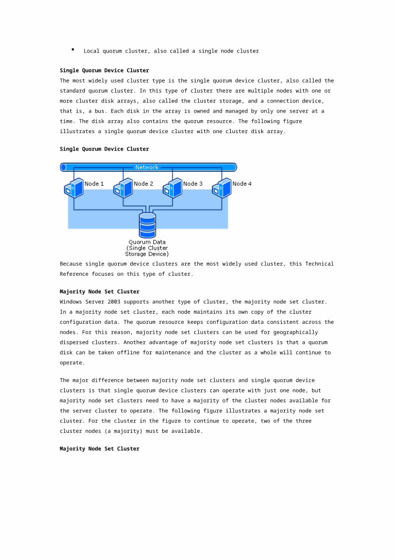
Single Quorum Device Cluster
The most widely used cluster type is the single quorum device cluster, also called the standard
quorum cluster. In this type of cluster there are multiple nodes with one or more cluster disk arrays,
also called the cluster storage, and a connection device, that is, a bus. Each disk in the array is owned
and managed by only one server at a time. The disk array also contains the quorum resource. The
following figure illustrates a single quorum device cluster with one cluster disk array.
Single Quorum Device Cluster
Because single quorum device clusters are the most widely used cluster, this Technical Reference
focuses on this type of cluster.
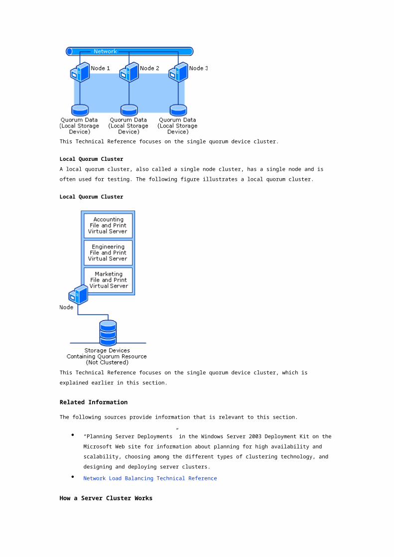
Majority Node Set Cluster
Windows Server 2003 supports another type of cluster, the majority node set cluster. In a majority
node set cluster, each node maintains its own copy of the cluster configuration data. The quorum
resource keeps configuration data consistent across the nodes. For this reason, majority node set
clusters can be used for geographically dispersed clusters. Another advantage of majority node set
clusters is that a quorum disk can be taken offline for maintenance and the cluster as a whole will
continue to operate.
The major difference between majority node set clusters and single quorum device clusters is that
single quorum device clusters can operate with just one node, but majority node set clusters need to
have a majority of the cluster nodes available for the server cluster to operate. The following figure
illustrates a majority node set cluster. For the cluster in the figure to continue to operate, two of the
three cluster nodes (a majority) must be available.
Majority Node Set Cluster
This Technical Reference focuses on the single quorum device cluster.
Local Quorum Cluster
A local quorum cluster, also called a single node cluster, has a single node and is often used for
testing. The following figure illustrates a local quorum cluster.
Local Quorum Cluster
This Technical Reference focuses on the single quorum device cluster, which is explained earlier in this
section.
Related Information
The following sources provide information that is relevant to this section.
“Planning Server Deployments” in the Windows Server 2003 Deployment Kit on the Microsoft
Web site for information about planning for high availability and scalability, choosing among
the different types of clustering technology, and designing and deploying server clusters.
Network Load Balancing Technical Reference
How a Server Cluster Works
In this section
Server Cluster Architecture
Server Cluster API
Server Cluster Processes
Related Information
A server cluster is a collection of servers, called nodes that communicate with each other to make a
set of services highly available to clients. Server clusters are based on one of the two clustering
technologies in the Microsoft Windows Server 2003 operating systems. The other clustering technology
is Network Load Balancing. Server clusters are designed for applications that have long-running in-
memory state or frequently updated data. Typical uses for server clusters include file servers, print
servers, database servers, and messaging servers.
This section provides technical background information about how the components within a server
cluster work.
Server Cluster Architecture
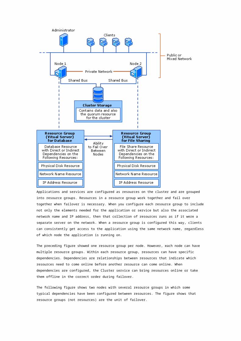
The most basic type of cluster is a two-node cluster with a single quorum device. For a definition of a
single quorum device, see “What Is a Server Cluster?.” The following figure illustrates the basic
elements of a server cluster, including nodes, resource groups, and the single quorum device, that is,
the cluster storage.
Basic Elements of a Two-Node Cluster with Single Quorum Device
Applications and services are configured as resources on the cluster and are grouped into resource
groups. Resources in a resource group work together and fail over together when failover is necessary.
When you configure each resource group to include not only the elements needed for the application
or service but also the associated network name and IP address, then that collection of resources runs
as if it were a separate server on the network. When a resource group is configured this way, clients
can consistently get access to the application using the same network name, regardless of which node
the application is running on.
The preceding figure showed one resource group per node. However, each node can have multiple
resource groups. Within each resource group, resources can have specific dependencies.
Dependencies are relationships between resources that indicate which resources need to come online
before another resource can come online. When dependencies are configured, the Cluster service can
bring resources online or take them offline in the correct order during failover.
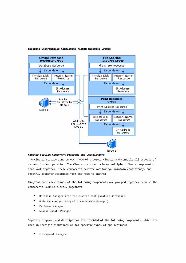
The following figure shows two nodes with several resource groups in which some typical
dependencies have been configured between resources. The figure shows that resource groups (not
resources) are the unit of failover.
Resource Dependencies Configured Within Resource Groups
Cluster Service Component Diagrams and Descriptions
The Cluster service runs on each node of a server cluster and controls all aspects of server cluster
operation. The Cluster service includes multiple software components that work together. These
components perform monitoring, maintain consistency, and smoothly transfer resources from one
node to another.
Diagrams and descriptions of the following components are grouped together because the
components work so closely together:
Database Manager (for the cluster configuration database)
Node Manager (working with Membership Manager)
Failover Manager
Global Update Manager
Separate diagrams and descriptions are provided of the following components, which are used in
specific situations or for specific types of applications:
Checkpoint Manager
Log Manager (quorum logging)
Event Log Replication Manager
Backup and Restore capabilities in Failover Manager
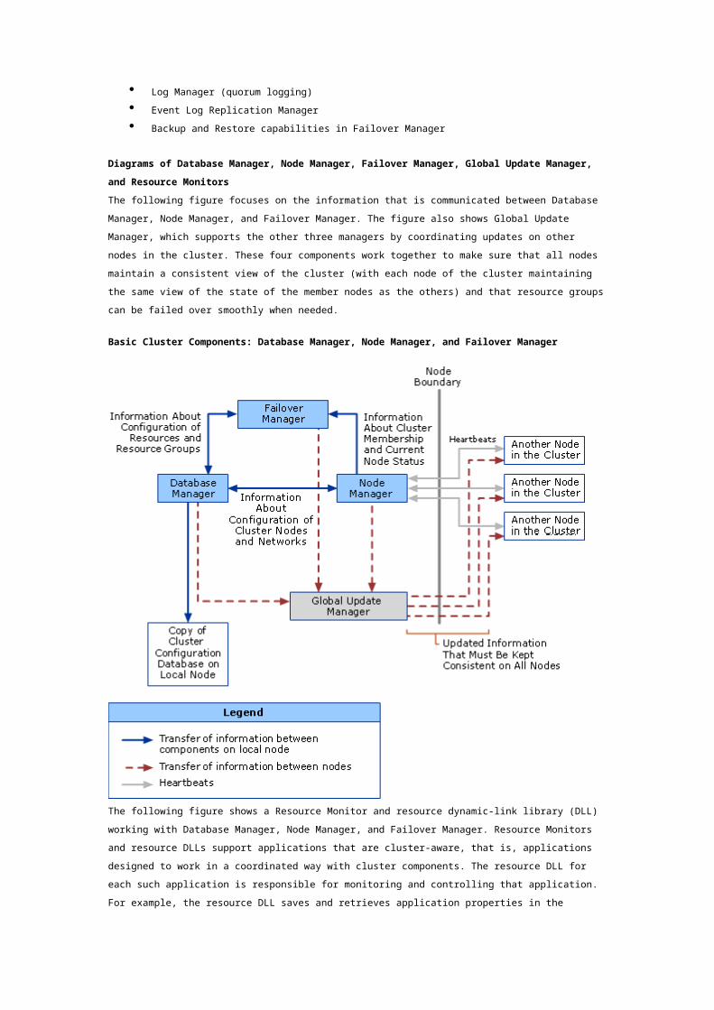
Diagrams of Database Manager, Node Manager, Failover Manager, Global Update Manager,
and Resource Monitors
The following figure focuses on the information that is communicated between Database Manager,
Node Manager, and Failover Manager. The figure also shows Global Update Manager, which supports
the other three managers by coordinating updates on other nodes in the cluster. These four
components work together to make sure that all nodes maintain a consistent view of the cluster (with
each node of the cluster maintaining the same view of the state of the member nodes as the others)
and that resource groups can be failed over smoothly when needed.
Basic Cluster Components: Database Manager, Node Manager, and Failover Manager
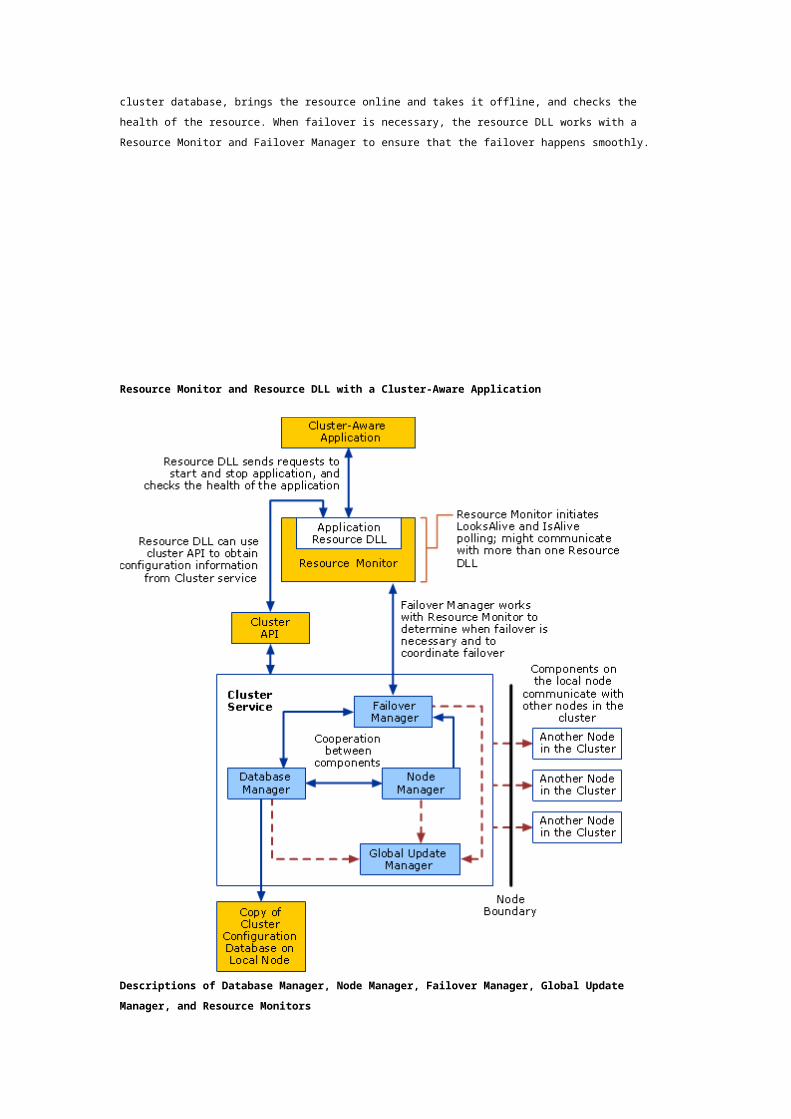
The following figure shows a Resource Monitor and resource dynamic-link library (DLL) working with
Database Manager, Node Manager, and Failover Manager. Resource Monitors and resource DLLs
support applications that are cluster-aware, that is, applications designed to work in a coordinated way
with cluster components. The resource DLL for each such application is responsible for monitoring and
controlling that application. For example, the resource DLL saves and retrieves application properties
in the cluster database, brings the resource online and takes it offline, and checks the health of the
resource. When failover is necessary, the resource DLL works with a Resource Monitor and Failover
Manager to ensure that the failover happens smoothly.
Resource Monitor and Resource DLL with a Cluster-Aware Application
Descriptions of Database Manager, Node Manager, Failover Manager, Global Update
Manager, and Resource Monitors
The following descriptions provide details about the components shown in the preceding diagrams.
Database Manager
Database Manager runs on each node and maintains a local copy of the cluster configuration
database, which contains information about all of the physical and logical items in a cluster. These
items include the cluster itself, cluster node membership, resource groups, resource types, and
descriptions of specific resources, such as disks and IP addresses. Database Manager uses the Global
Update Manager to replicate all changes to the other nodes in the cluster. In this way, consistent
configuration information is maintained across the cluster, even if conditions are changing such as if a
node fails and the administrator changes the cluster configuration before that node returns to service.
Database Manager also provides an interface through which other Cluster service components, such as
Failover Manager and Node Manager, can store changes in the cluster configuration database. The
interface for making such changes is similar to the interface for making changes to the registry
through the Windows application programming interface (API). The key difference is that changes
received by Database Manager are replicated through Global Update Manager to all nodes in the
cluster.
Database Manager functions used by other components
Some Database Manager functions are exposed through the cluster API. The primary purpose for
exposing Database Manager functions is to allow custom resource DLLs to save private properties to
the cluster database when this is useful for a particular clustered application. (A private property for a
resource is a property that applies to that resource type but not other resource types; for example, the
SubnetMask property applies for an IP Address resource but not for other resource types.) Database
Manager functions are also used to query the cluster database.
Node Manager
Node Manager runs on each node and maintains a local list of nodes, networks, and network interfaces
in the cluster. Through regular communication between nodes, Node Manager ensures that all nodes in
the cluster have the same list of functional nodes.
Node Manager uses the information in the cluster configuration database to determine which nodes
have been added to the cluster or evicted from the cluster. Each instance of Node Manager also
monitors the other nodes to detect node failure. It does this by sending and receiving messages, called
heartbeats, to each node on every available network. If one node detects a communication failure with
another node, it broadcasts a message to the entire cluster, causing all nodes that receive the
message to verify their list of functional nodes in the cluster. This is called a regroup event.
Node Manager also contributes to the process of a node joining a cluster. At that time, on the node
that is joining, Node Manager establishes authenticated communication (authenticated RPC bindings)
between itself and the Node Manager component on each of the currently active nodes.
Note
A down node is different from a node that has been evicted from the cluster. When you evict
a node from the cluster, it is removed from Node Manager’s list of potential cluster nodes. A
down node remains on the list of potential cluster nodes even while it is down; when the node
and the network it requires are functioning again, the node joins the cluster. An evicted node,
however, can become part of the cluster only after you use Cluster Administrator or
Cluster.exe to add the node back to the cluster.
Membership Manager
Membership Manager (also called the Regroup Engine) causes a regroup event whenever another
node’s heartbeat is interrupted (indicating a possible node failure). During a node failure and regroup
event, Membership Manager and Node Manager work together to ensure that all functioning nodes
agree on which nodes are functioning and which are not.
Cluster Network Driver
Node Manager and other components make use of the Cluster Network Driver, which supports specific
types of network communication needed in a cluster. The Cluster Network Driver runs in kernel mode
and provides support for a variety of functions, especially heartbeats and fault-tolerant communication
between nodes.
Failover Manager and Resource Monitors
Failover Manager manages resources and resource groups. For example, Failover Manager stops and
starts resources, manages resource dependencies, and initiates failover of resource groups. To
perform these actions, it receives resource and system state information from cluster components on
the node and from Resource Monitors. Resource Monitors provide the execution environment for
resource DLLs and support communication between resources DLLs and Failover Manager.
Failover Manager determines which node in the cluster should own each resource group. If it is
necessary to fail over a resource group, the instances of Failover Manager on each node in the cluster
work together to reassign ownership of the resource group.
Depending on how the resource group is configured, Failover Manager can restart a failing resource
locally or can take the failing resource offline along with its dependent resources, and then initiate
failover.
Global Update Manager
Global Update Manager makes sure that when changes are copied to each of the nodes, the following
takes place:
Changes are made atomically, that is, either all healthy nodes are updated, or none are
updated.
Changes are made in the order they occurred, regardless of the origin of the change. The
process of making changes is coordinated between nodes so that even if two different
changes are made at the same time on different nodes, when the changes are replicated they
are put in a particular order and made in that order on all nodes.
Global Update Manager is used by internal cluster components, such as Failover Manager, Node
Manager, or Database Manager, to carry out the replication of changes to each node. Global updates
are typically initiated as a result of a Cluster API call. When an update is initiated by a node, another
node is designated to monitor the update and make sure that it happens on all nodes. If that node
cannot make the update locally, it notifies the node that tried to initiate the update, and changes are
not made anywhere (unless the operation is attempted again). If the node that is designated to
monitor the update can make the update locally, but then another node cannot be updated, the node
that cannot be updated is removed from the list of functional nodes, and the change is made on
available nodes. If this happens, quorum logging is enabled at the same time, which ensures that the
failed node receives all necessary configuration information when it is functioning again, even if the
original set of nodes is down at that time.
Diagram and Description of Checkpoint Manager
Some applications store configuration information locally instead of or in addition to storing
information in the cluster configuration database. Applications might store information locally in two
ways. One way is to store configuration information in the registry on the local server; another way is
to use cryptographic keys on the local server. If an application requires that locally-stored information
be available on failover, Checkpoint Manager provides support by maintaining a current copy of the
local information on the quorum resource.
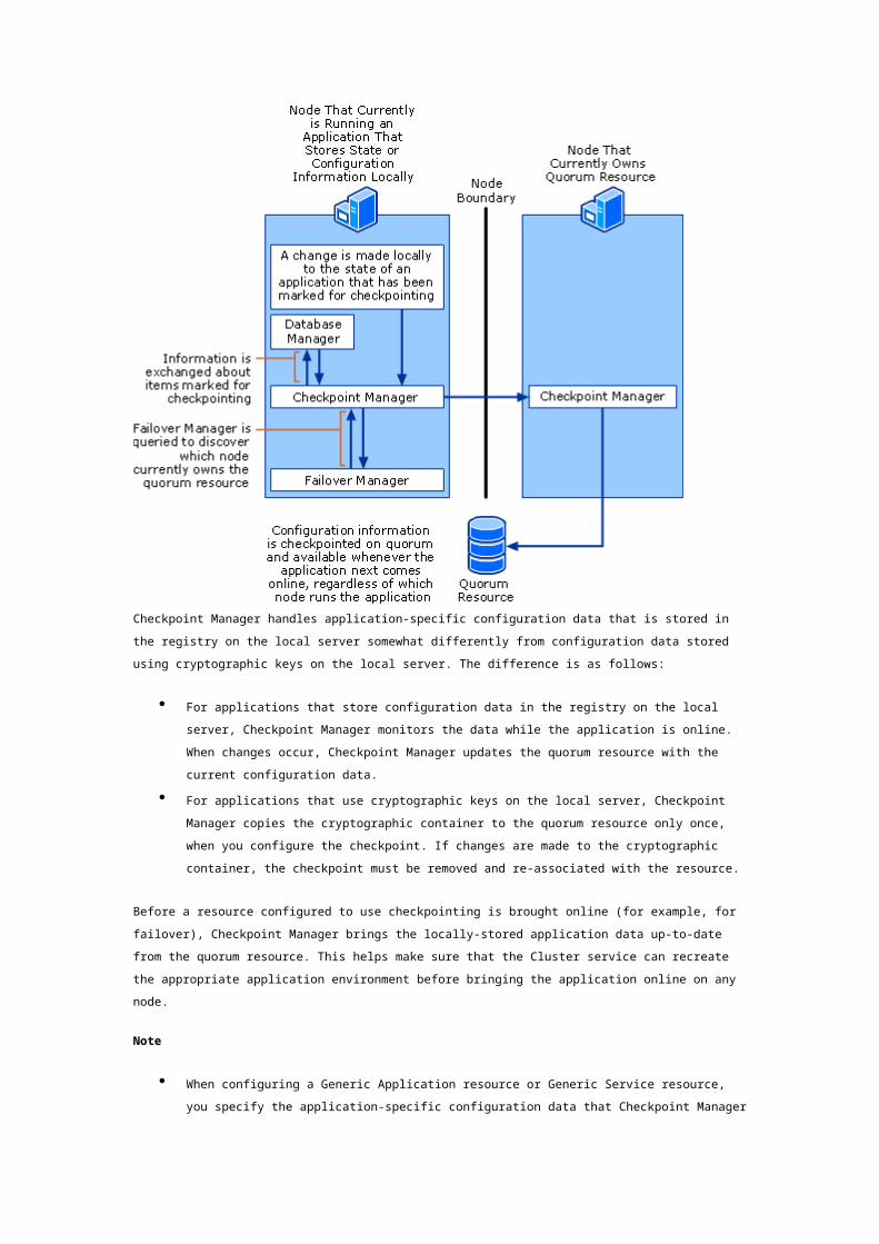
The following figure shows the Checkpoint Manager process.
Checkpoint Manager
Checkpoint Manager handles application-specific configuration data that is stored in the registry on the
local server somewhat differently from configuration data stored using cryptographic keys on the local
server. The difference is as follows:
For applications that store configuration data in the registry on the local server, Checkpoint
Manager monitors the data while the application is online. When changes occur, Checkpoint
Manager updates the quorum resource with the current configuration data.
For applications that use cryptographic keys on the local server, Checkpoint Manager copies
the cryptographic container to the quorum resource only once, when you configure the
checkpoint. If changes are made to the cryptographic container, the checkpoint must be
removed and re-associated with the resource.
Before a resource configured to use checkpointing is brought online (for example, for failover),
Checkpoint Manager brings the locally-stored application data up-to-date from the quorum resource.
This helps make sure that the Cluster service can recreate the appropriate application environment
before bringing the application online on any node.
Note

When configuring a Generic Application resource or Generic Service resource, you specify the
application-specific configuration data that Checkpoint Manager monitors and copies. When
determining which configuration information must be marked for checkpointing, focus on the
information that must be available when the application starts.
Checkpoint Manager also supports resources that have application-specific registry trees (not just
individual keys) that exist on the cluster node where the resource comes online. Checkpoint Manager
watches for changes made to these registry trees when the resource is online (not when it is offline).
When the resource is online and Checkpoint Manager detects that changes have been made, it creates
a copy of the registry tree on the owner node of the resource and then sends a message to the owner
node of the quorum resource, telling it to copy the file to the quorum resource. Checkpoint Manager
performs this function in batches so that frequent changes to registry trees do not place too heavy a
load on the Cluster service.
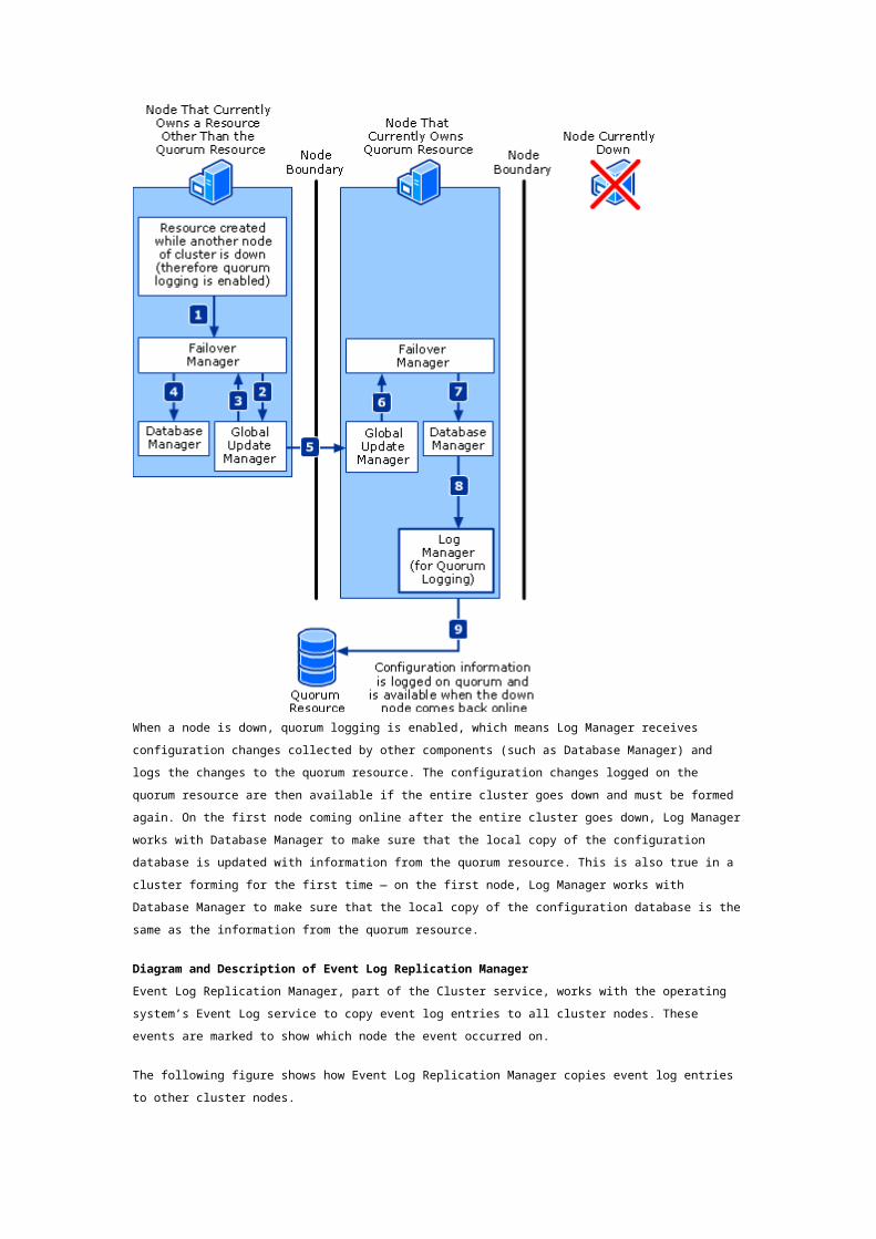
Diagram and Description of Log Manager (for Quorum Logging)
The following figure shows how Log Manager works with other components when quorum logging is
enabled (when a node is down).
Log Manager and Other Components Supporting Quorum Logging
When a node is down, quorum logging is enabled, which means Log Manager receives configuration
changes collected by other components (such as Database Manager) and logs the changes to the

quorum resource. The configuration changes logged on the quorum resource are then available if the
entire cluster goes down and must be formed again. On the first node coming online after the entire
cluster goes down, Log Manager works with Database Manager to make sure that the local copy of the
configuration database is updated with information from the quorum resource. This is also true in a
cluster forming for the first time — on the first node, Log Manager works with Database Manager to
make sure that the local copy of the configuration database is the same as the information from the
quorum resource.
Diagram and Description of Event Log Replication Manager
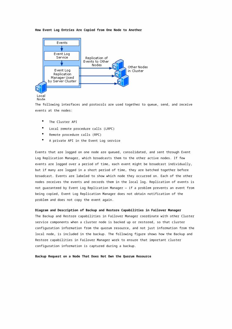
Event Log Replication Manager, part of the Cluster service, works with the operating system’s Event
Log service to copy event log entries to all cluster nodes. These events are marked to show which
node the event occurred on.
The following figure shows how Event Log Replication Manager copies event log entries to other
cluster nodes.
How Event Log Entries Are Copied from One Node to Another
The following interfaces and protocols are used together to queue, send, and receive events at the
nodes:
The Cluster API
Local remote procedure calls (LRPC)
Remote procedure calls (RPC)
A private API in the Event Log service
Events that are logged on one node are queued, consolidated, and sent through Event Log Replication
Manager, which broadcasts them to the other active nodes. If few events are logged over a period of
time, each event might be broadcast individually, but if many are logged in a short period of time, they
are batched together before broadcast. Events are labeled to show which node they occurred on. Each
of the other nodes receives the events and records them in the local log. Replication of events is not
guaranteed by Event Log Replication Manager — if a problem prevents an event from being copied,
Event Log Replication Manager does not obtain notification of the problem and does not copy the
event again.
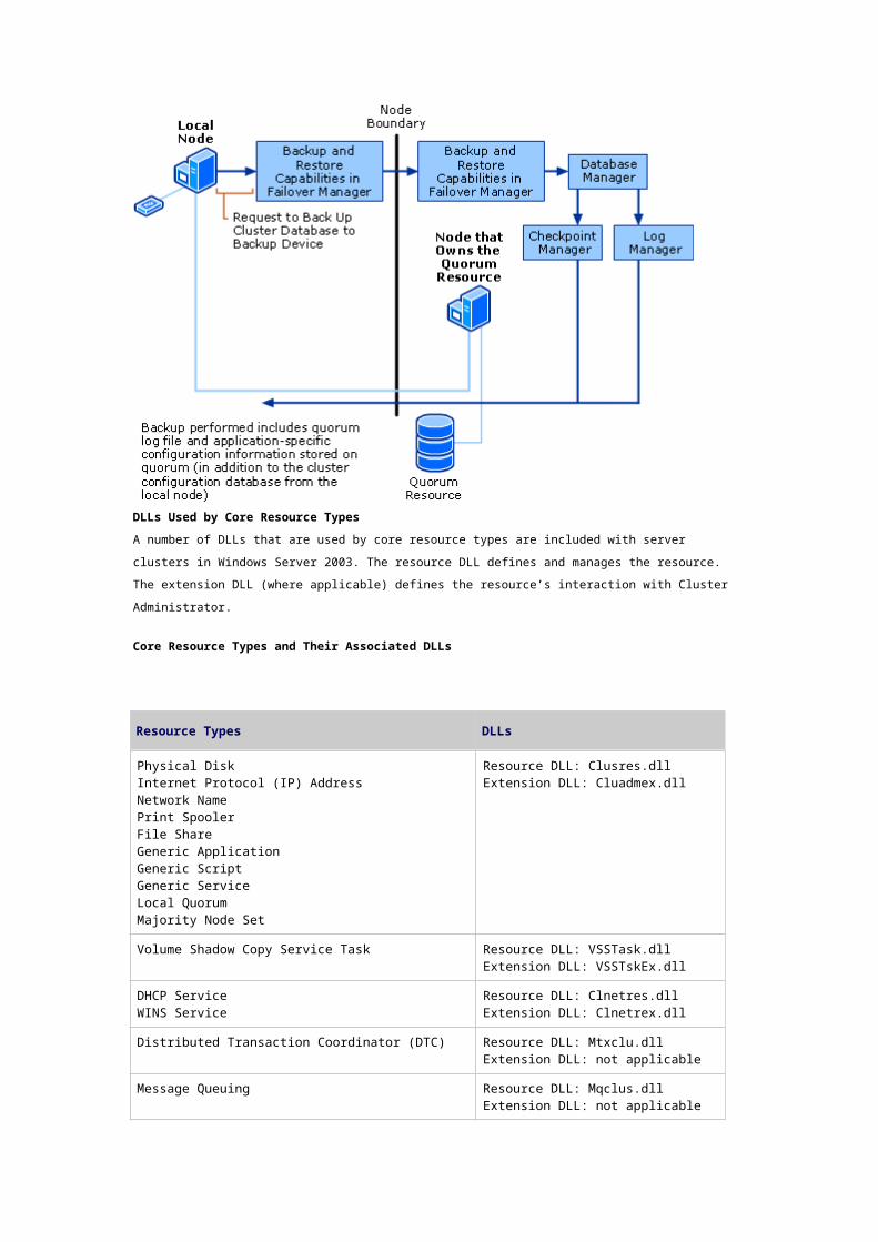
Diagram and Description of Backup and Restore Capabilities in Failover Manager
The Backup and Restore capabilities in Failover Manager coordinate with other Cluster service
components when a cluster node is backed up or restored, so that cluster configuration information
from the quorum resource, and not just information from the local node, is included in the backup. The
following figure shows how the Backup and Restore capabilities in Failover Manager work to ensure
that important cluster configuration information is captured during a backup.
Backup Request on a Node That Does Not Own the Quorum Resource
DLLs Used by Core Resource Types
A number of DLLs that are used by core resource types are included with server clusters in
Windows Server 2003. The resource DLL defines and manages the resource. The extension DLL (where
applicable) defines the resource’s interaction with Cluster Administrator.
Core Resource Types and Their Associated DLLs
Resource Types DLLs
Physical DiskInternet Protocol (IP) AddressNetwork NamePrint SpoolerFile ShareGeneric ApplicationGeneric ScriptGeneric ServiceLocal QuorumMajority Node Set
Resource DLL: Clusres.dll Extension DLL: Cluadmex.dll
Volume Shadow Copy Service Task Resource DLL: VSSTask.dll Extension DLL: VSSTskEx.dll
DHCP ServiceWINS Service
Resource DLL: Clnetres.dll Extension DLL: Clnetrex.dll
Distributed Transaction Coordinator (DTC) Resource DLL: Mtxclu.dll Extension DLL: not applicable
Message Queuing Resource DLL: Mqclus.dll Extension DLL: not applicable
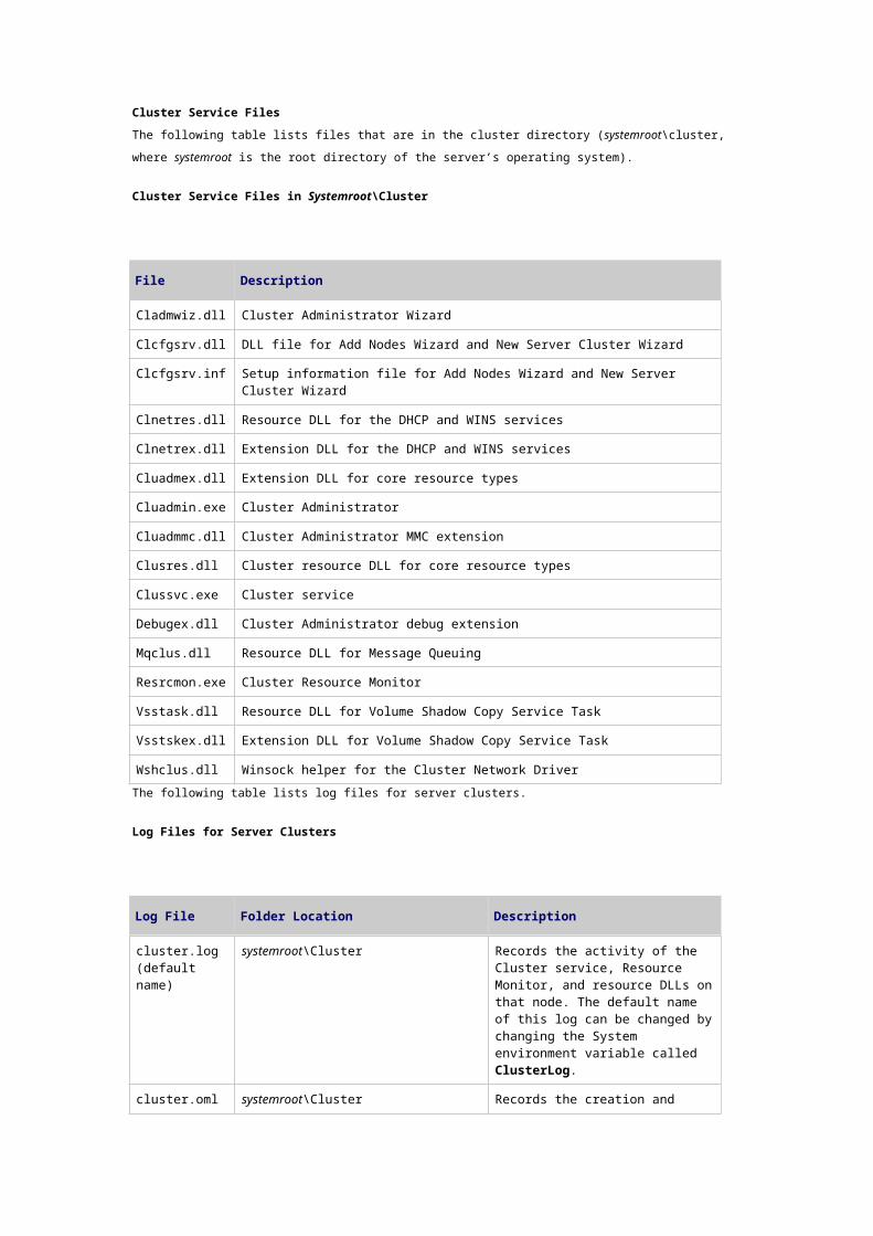
Cluster Service Files
The following table lists files that are in the cluster directory (systemroot\cluster, where systemroot is
the root directory of the server’s operating system).

Cluster Service Files in Systemroot\Cluster
File Description
Cladmwiz.dll Cluster Administrator Wizard
Clcfgsrv.dll DLL file for Add Nodes Wizard and New Server Cluster Wizard
Clcfgsrv.inf Setup information file for Add Nodes Wizard and New Server Cluster Wizard
Clnetres.dll Resource DLL for the DHCP and WINS services
Clnetrex.dll Extension DLL for the DHCP and WINS services
Cluadmex.dll Extension DLL for core resource types
Cluadmin.exe Cluster Administrator
Cluadmmc.dll Cluster Administrator MMC extension
Clusres.dll Cluster resource DLL for core resource types
Clussvc.exe Cluster service
Debugex.dll Cluster Administrator debug extension
Mqclus.dll Resource DLL for Message Queuing
Resrcmon.exe Cluster Resource Monitor
Vsstask.dll Resource DLL for Volume Shadow Copy Service Task
Vsstskex.dll Extension DLL for Volume Shadow Copy Service Task
Wshclus.dll Winsock helper for the Cluster Network Driver
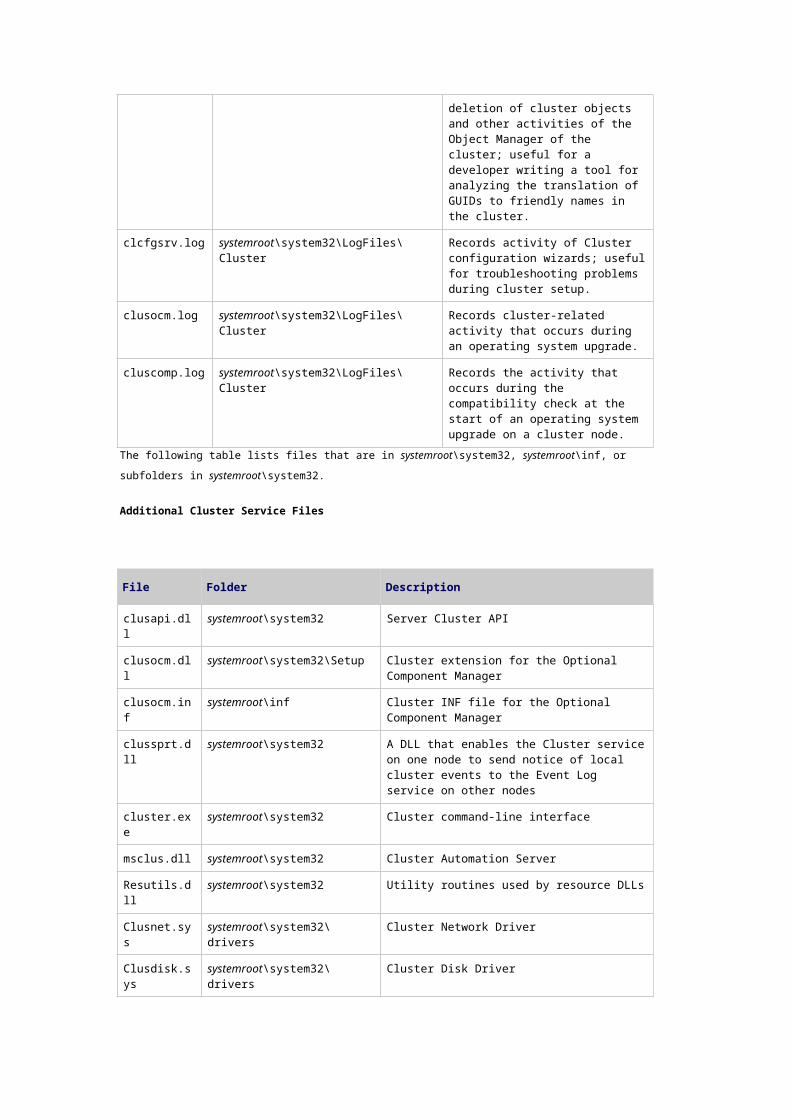
The following table lists log files for server clusters.
Log Files for Server Clusters
Log File Folder Location Description
cluster.log (default name)
systemroot\Cluster Records the activity of the Cluster service, Resource Monitor, and resource DLLs on that node. The default name of this log can be changed by changing the System environment variable called ClusterLog.
cluster.oml systemroot\Cluster Records the creation and deletion of cluster objects and other activities of the Object Manager of the cluster; useful for a developer writing a tool for analyzing the translation of GUIDs to friendly names in the cluster.
clcfgsrv.log systemroot\system32\LogFiles\Cluster Records activity of Cluster configuration wizards; useful for troubleshooting problems during cluster setup.
clusocm.log systemroot\system32\LogFiles\Cluster Records cluster-related activity that occurs during an operating
system upgrade.
cluscomp.log systemroot\system32\LogFiles\Cluster Records the activity that occurs during the compatibility check at the start of an operating system upgrade on a cluster node.
The following table lists files that are in systemroot\system32, systemroot\inf, or subfolders in
systemroot\system32.
Additional Cluster Service Files
File Folder Description
clusapi.dll systemroot\system32 Server Cluster API
clusocm.dll systemroot\system32\Setup Cluster extension for the Optional Component Manager
clusocm.inf systemroot\inf Cluster INF file for the Optional Component Manager
clussprt.dll systemroot\system32 A DLL that enables the Cluster service on one node to send notice of local cluster events to the Event Log service on other nodes
cluster.exe systemroot\system32 Cluster command-line interface
msclus.dll systemroot\system32 Cluster Automation Server
Resutils.dll systemroot\system32 Utility routines used by resource DLLs
Clusnet.sys systemroot\system32\drivers Cluster Network Driver
Clusdisk.sys systemroot\system32\drivers Cluster Disk Driver
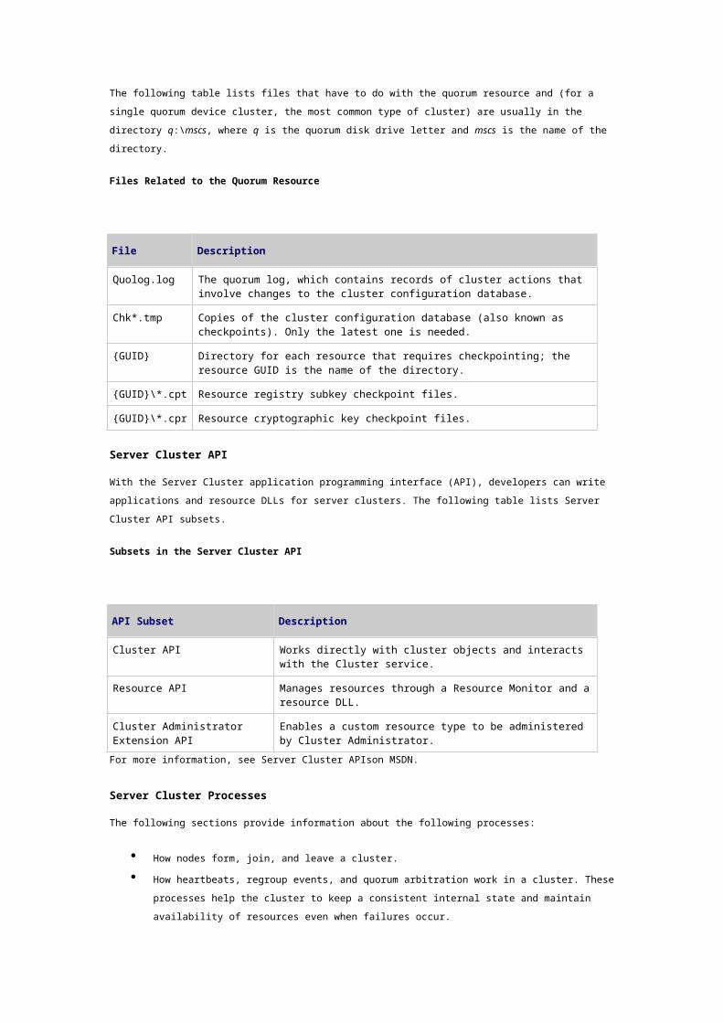
The following table lists files that have to do with the quorum resource and (for a single quorum device
cluster, the most common type of cluster) are usually in the directory q:\mscs, where q is the quorum
disk drive letter and mscs is the name of the directory.
Files Related to the Quorum Resource
File Description
Quolog.log The quorum log, which contains records of cluster actions that involve changes to the cluster configuration database.
Chk*.tmp Copies of the cluster configuration database (also known as checkpoints). Only the latest one is needed.
{GUID} Directory for each resource that requires checkpointing; the resource GUID is the name of the directory.
{GUID}\*.cpt Resource registry subkey checkpoint files.
{GUID}\*.cpr Resource cryptographic key checkpoint files.
Server Cluster API
With the Server Cluster application programming interface (API), developers can write applications and
resource DLLs for server clusters. The following table lists Server Cluster API subsets.
Subsets in the Server Cluster API
API Subset Description
Cluster API Works directly with cluster objects and interacts with the Cluster service.
Resource API Manages resources through a Resource Monitor and a resource DLL.
Cluster Administrator Extension API
Enables a custom resource type to be administered by Cluster Administrator.
For more information, see Server Cluster APIson MSDN.
Server Cluster Processes
The following sections provide information about the following processes:
How nodes form, join, and leave a cluster.
How heartbeats, regroup events, and quorum arbitration work in a cluster. These processes
help the cluster to keep a consistent internal state and maintain availability of resources even
when failures occur.
How resource groups are brought online, taken offline, failed over, and failed back.
How Nodes Form, Join, and Leave a Cluster
Nodes must form, join, and leave a cluster in a coordinated way so that the following are always true:
Only one node owns the quorum resource at any given time.
All nodes maintain the same list of functioning nodes in the cluster.
All nodes can maintain consistent copies of the cluster configuration database.
Forming a Cluster
The first server that comes online in a cluster, either after installation or after the entire cluster has
been shut down for some reason, forms the cluster. To succeed at forming a cluster, a server must:
Be running the Cluster service.
Be unable to locate any other nodes in the cluster (in other words, no other nodes can be
running).
Acquire exclusive ownership of the quorum resource.
If a node attempts to form a cluster and is unable to read the quorum log, the Cluster service will not
start, because it cannot guarantee that it has the latest copy of the cluster configuration. In other
words, the quorum log ensures that when a cluster forms, it uses the same configuration it was using
when it last stopped.
The sequence in which a node forms a cluster is as follows:
1. The node confirms that it can start the Cluster service.
2. The node reviews the information stored in the local copy of the cluster configuration
database.
3. Using information from the local copy of the cluster configuration database, the node
confirms that no other nodes are running.
If another node is running, then the node that started most recently joins the cluster instead
of forming it.
4. Using information from the local copy of the cluster configuration database, the node locates
the quorum resource.
5. The node confirms that it can acquire exclusive ownership of the quorum resource and that it
can read from the quorum resource. If it can, the node takes ownership.
6. The node compares the sequence numbers on the copy of the cluster configuration database
on the quorum resource and the sequence numbers on the quorum log against the sequence
numbers on the node’s local copy of the cluster configuration database.
7. The node updates its local copy of the cluster configuration database with any newer
information that might be stored on the quorum resource.
8. The node begins to bring resources and resource groups online.
Joining a Cluster
The sequence in which a server joins an existing cluster is as follows:
1. The node confirms that it can start the Cluster service.
2. The node reviews the information stored in the local copy of the cluster configuration
database.
3. The node that is joining the cluster tries to locate another node (sometimes called a sponsor
node) running in the cluster. The node goes through the list of other nodes in its local
configuration database, trying one or more until one responds.
If no other nodes respond, the node tries to form the cluster, starting by locating the quorum
resource.
4. Node Manager on the sponsor node authenticates the new node. If the joining node is not
recognized as a cluster member, the request to join the cluster is refused.
5. Node Manager on the joining node establishes authenticated communication (authenticated
RPC bindings) between itself and the Node Manager component on each of the currently
active nodes.
6. Database Manager on the joining node checks the local copy of the configuration database. If
it is outdated, Database Manager obtains an updated copy from the sponsor node.
Leaving a Cluster
A node can leave a cluster when the node shuts down or when the Cluster service is stopped. When a
node leaves a cluster during a planned shutdown, it attempts to perform a smooth transfer of resource
groups to other nodes. The node leaving the cluster then initiates a regroup event.
Functioning nodes in a cluster can also force another node to leave the cluster if the node cannot
perform cluster operations, for example, if it fails to commit an update to the cluster configuration
database.
Heartbeats, Regroup Events, and Quorum Arbitration
When server clusters encounter changing circumstances and possible failures, the following processes
help the cluster to keep a consistent internal state and maintain availability of resources:
Heartbeats
Regroup events
Quorum arbitration
Heartbeats
Heartbeats are single User Datagram Protocol (UDP) packets exchanged between nodes once
every 1.2 seconds to confirm that each node is still available. If a node is absent for five consecutive
heartbeats, the node that detected the absence initiates a regroup event to make sure that all nodes
reach agreement on the list of nodes that remain available.
Server cluster networks can be private (node-to-node communication only), public (client-to-node
communication), or mixed (both node-to-node and client-to-node communication). Heartbeats are
communicated across all networks; however, the monitoring of heartbeats and the way the cluster
interprets missed heartbeats depends on the type of network:
On private or mixed networks, which both carry node-to-node communication, heartbeats are
monitored to determine whether the node is functioning in the cluster.
A series of missed heartbeats can either mean that the node is offline or that all private and
mixed networks are offline; in either case, a node has lost its ability to function in the cluster.
On public networks, which carry only client-to-node communication, heartbeats are monitored
only to determine whether a node’s network adapter is functioning.
Regroup Events
If a node is absent for five consecutive heartbeats, a regroup event occurs. (Membership Manager,
described earlier, starts the regroup event.)
If an individual node remains unresponsive, the node is removed from the list of functional nodes. If
the unresponsive node was the owner of the quorum resource, the remaining nodes also begin the
quorum arbitration process. After this, failover begins.
Quorum Arbitration
Quorum arbitration is the process that occurs when the node that owned the quorum resource fails or
is unavailable, and the remaining nodes determine which node will take ownership. When a regroup
event occurs and the unresponsive node owned the quorum resource, another node is designated to
initiate quorum arbitration. A basic goal for quorum arbitration is to make sure that only one node
owns the quorum resource at any given time.
It is important that only one node owns the quorum resource because if all network communication
between two or more cluster nodes fails, it is possible for the cluster to split into two or more partial
clusters that will try to keep functioning (sometimes called a “split brain” scenario). Server clusters
prevent this by allowing only the partial cluster with a node that owns the quorum resource to
continue as the cluster. Any nodes that cannot communicate with the node that owns the quorum
resource stop working as cluster nodes.
How Clusters Keep Resource Groups Available
This section describes how clusters keep resource groups available by monitoring the health of
resources (polling), bringing resource groups online, and carrying out failover. Failover means
transferring ownership of the resources within a group from one node to another. This section also
describes how resource groups are taken offline as well as how they are failed back, that is, how
resource groups are transferred back to a preferred node after that node has come back online.
Transferring ownership can mean somewhat different things depending on which of the group’s
resources is being transferred. For an application or service, the application or service is stopped on
one node and started on another. For an external device, such as a Physical Disk resource, the right to
access the device is transferred. Similarly, the right to use an IP address or a network name can be
transferred from one node to another.
Resource-related activities in server clusters include:
Monitoring the health of resources (polling).
Bringing a resource group online.
Taking a resource group offline.
Failing a resource group over.
Failing a resource group back.
The administrator of the cluster initiates resource group moves, usually for maintenance or other
administrative tasks. Group moves initiated by an administrator are similar to failovers in that the
Cluster service initiates resource transitions by issuing commands to Resource Monitor through
Failover Manager.
Resource Health Monitoring (Polling)
Resource Monitor conducts two kinds of polling on each resource that it monitors: Looks Alive
(resource appears to be online) and Is Alive (a more thorough check indicates the resource is online
and functioning properly).
When setting polling intervals, it can be useful to understand the following:
If a Generic Application resource has a long startup time, you can lengthen the polling interval
to allow the resource to finish starting up. In other words, you might not require a custom
resource DLL to ensure that the resource is given the necessary startup time.
If you lengthen the polling intervals, you reduce the chance that polls will interfere with each
other (the chance for lock contention).
You can bypass Looks Alive polling by setting the interval to 0.
How a Resource Group Comes Online
The following sequence is used when Failover Manager and Resource Monitor bring a resource group
online.
1. Failover Manager uses the dependency list (in the cluster configuration) to determine the
appropriate order in which to bring resources online.
2. Failover Manager works with Resource Monitor to begin bringing resources online. The first
resource or resources started are ones that do not depend on other resources.
3. Resource Monitor calls the Online entry point of the first resource DLL and returns the result
to Failover Manager.
If the entry point returns ERROR_IO_PENDING, the resource state changes to
OnlinePending. Resource Monitor starts a timer that waits for the resource either to
go online or to fail. If the amount of time specified for the pending timeout passes
and the resource is still pending (has not entered either the Online or Failed state),
the resource is treated as a failed resource and Failover Manager is notified.
If the Online call fails or the Online entry point does not move the resource into the
Online state within the time specified in the resource DLL, the resource enters the
Failed state, and Failover Manager uses Resource Monitor to try to restart the
resource, according to the policies defined for the resource in its DLL.
When the resource enters the Online state, Resource Monitor adds the resource to
its list of resources and starts monitoring the state of the resource.
4. The sequence is repeated as Failover Manager brings the next resource online. Failover
Manager uses the dependency list to determine the correct order for bringing resources
online.
After resources have been brought online, Failover Manager works with Resource Monitor to determine
if and when failover is necessary and to coordinate failover.
How a Resource Group Goes Offline
Failover Manager takes a resource group offline as part of the failover process or when an
administrator moves the group for maintenance purposes. The following sequence is used when
Failover Manager takes a resource group offline:
1. Failover Manager uses the dependency list (in the cluster configuration) to determine the
appropriate order in which to bring resources offline.
2. Failover Manager works with Resource Monitor to begin taking resources offline. The first
resource or resources stopped are ones on which other resources do not depend.
3. Resource Monitor calls the Offline entry point of the resource DLL and returns the result to
Failover Manager.
If the entry point returns ERROR_IO_PENDING, the resource state changes to
OfflinePending. Resource Monitor starts a timer that waits for the resource either
to go offline or to fail. If the amount of time specified for the pending timeout passes
and the resource is still pending (has not entered either the Offline or Failed state),
the resource is treated as a failed resource and Failover Manager is notified.
If the Offline call fails or the Offline entry point does not move the resource into the
Offline state within the time specified in the resource DLL, Failover Manager uses
Resource Monitor to terminate the resource and the resource enters the Failed state.
If the Offline call succeeds, Resource Monitor takes the resource off its list and stops
monitoring the resource.
4. The sequence is repeated as Failover Manager brings the next resource offline. Failover
Manager uses the dependency list to determine the correct order for taking resources offline.
How Failover Occurs
Group failover happens when the group or the node that owns the group fails. Individual resource
failure causes the group to fail if you configure the Affect the group property for the resource.
Failover takes two forms, as described in the sections that follow:
Resource failure and group failure (without node failure)
Node failure or loss of communication between nodes
Resource Failure and Group Failure (Without Node Failure)
When a resource fails, the following process occurs:
1. Resource Monitor detects the failure, either through Looks Alive or Is Alive polling or through
an event signaled by the resource. Resource Monitor calls the IsAlive entry point of the
resource DLL to confirm that the resource has failed.
2. If IsAlive fails, the state of the resource changes to Failed.
If you configured the resource to be restarted on failure, Failover Manager attempts to restart
the resource by trying to bring it online. If the attempts to bring the resource online fail more
than is allowed by the restart Threshold and Period properties, Resource Monitor stops
polling the resource.
3. Through Resource Monitor, Failover Manager calls the Terminate entry point of the resource
DLL.
The rest of this process concerns how the group fails over.
4. If the resource is set to Affect the group, the sequence continues. Otherwise, it ends
without further action. If the resource is set to Affect the group, Failover Managers on the
cluster nodes work together to reassign ownership of the group.
5. On the node on which the resource failed, Failover Manager terminates the resource that
failed and the resources that depend on it, and then Failover Manager takes the remaining
resources in the dependency tree offline in order of dependencies.
6. Failover Manager on the node on which the resource failed notifies Failover Manager on the
node that will take ownership of the resource (and also notifies Failover Manager on other
nodes about the changes that are happening).
7. If any of the resources have been configured so that application-specific configuration
information (registry subkeys) for that resource is checkpointed, Checkpoint Manager restores
the saved registry subkeys for those resources from the quorum resource.
8. The destination node Failover Manager brings the resources online one by one, using the
dependency list to determine the correct order.
9. The node that now owns the group turns control of the group’s resources over to their
respective Resource Monitors.
Node Failure or Loss of Communication Between Nodes
Failover that occurs when a node fails is different from failover that occurs when a resource fails. For
the purposes of clustering, a node is considered to have failed if it loses communication with other
nodes.
As described in previous sections, if a node misses five heartbeats, this indicates that it has failed, and
a regroup event (and possibly quorum arbitration) occurs. After node failure, surviving nodes negotiate
for ownership of the various resource groups. On two-node clusters the result is obvious, but on
clusters with more than two nodes, Failover Manager on the surviving nodes determines group
ownership based on the following:
The nodes you have specified as possible owners of the affected resource groups.
The order in which you specified the nodes in the group’s Preferred Owners list.
Note
When setting up a preferred owners list for a resource group, we recommend that you list all
nodes in your server cluster and put them in priority order.
How Failback Occurs
Failback is the process by which the Cluster service moves resource groups back to their preferred
node after the node has failed and come back online. You can configure both whether and when
failback occurs. By default, groups are not set to fail back.
The node to which the group will fail back initiates the failback. Failover Manager on that node
contacts Failover Manager on the node where the group is currently online and negotiates for
ownership. The instances of Failover Manager on the two nodes work together to smoothly transfer
ownership of the resource group back to the preferred node.
You can test failback configuration settings by following procedures in Help and Support Center.
Related Information
The following sources provide information that is relevant to this section.
“Planning Server Deployments” in the Windows Server 2003 Deployment Kit on the Microsoft
Web site for more information about failover policies, choices for cluster storage, and ways
that applications can operate within a server cluster.
What Is a Server Cluster?
Server Cluster Tools and Settings
Updated: March 28, 2003
Server Cluster Tools and Settings
In this section
Server Cluster Tools
Server Cluster WMI Classes
Related Information
The information in this section is helpful for learning about tools to administer, diagnose, and recover
server clusters. It also provides information about tools for configuring disks and for migrating a
clustered print server to Windows Server 2003 operating systems. In addition, this section provides
information about WMI classes associated with server clusters.
Server Cluster Tools
The following tools are associated with server clusters.
Cluadmin.exe: Cluster Administrator
Category
Tool included in Windows Server 2003, Standard Edition, Windows Server 2003, Enterprise Edition, and
Windows Server 2003, Datacenter Edition, operating systems. The tool is also included in the Windows
Server 2003 Administration Tools Pack.
Version Compatibility
Cluster Administrator can run on computers running Windows Server 2003, Standard Edition, Windows
Server 2003, Enterprise Edition, Windows Server 2003, Datacenter Edition, and Windows XP
Professional with Windows Server 2003 Administration Tools Pack installed.
Cluster Administrator can target server cluster nodes running Windows Server 2003, Enterprise
Edition, Windows Server 2003, Datacenter Edition, Windows 2000 Advanced Server, Windows 2000
Datacenter Server, and Windows NT Server 4.0, Enterprise Edition.
Cluster Administrator is the graphical user interface (GUI) for server clusters. It displays information
about the cluster and its nodes, resources, and groups. With Cluster Administrator, you can do a
variety of tasks, including joining nodes to a cluster, managing cluster objects, establishing groups,
initiating failover, monitoring cluster activity, and other tasks.
Cluster.exe
Category
Tool included in Windows Server 2003, Standard Edition, Windows Server 2003, Enterprise Edition, and
Windows Server 2003, Datacenter Edition, operating systems. The tool is also included in the Windows
Server 2003 Administration Tools Pack.
Version Compatibility
Cluster.exe can run on computers running Windows Server 2003, Standard Edition, Windows
Server 2003, Enterprise Edition, Windows Server 2003, Datacenter Edition, and Windows XP
Professional with Windows Server 2003 Administration Tools Pack installed.
Cluster.exe can target server cluster nodes that are running Windows Server 2003, Enterprise Edition,
Windows Server 2003, Datacenter Edition, Windows 2000 Advanced Server, Windows 2000 Datacenter
Server, and Windows NT Server 4.0, Enterprise Edition.
Cluster.exe is the command-line interface for server clusters. Cluster.exe provides all the
functionality of Cluster Administrator, the graphical user interface (GUI), plus several
additional functions:
The cluster resource command includes the /private option, which can be used to view or
change a resource’s private properties in the cluster configuration database.
The cluster command includes the /changepass option, which can be used to change the
Cluster service account password.
The cluster resource command (with no options) can provide information about a cluster
resource when Cluster Administrator does not display information quickly, which sometimes
happens if a resource is in a pending state.
Commands can be put together into scripts that can be run routinely, possibly by staff
members less highly trained than those who wrote the scripts.
For more information about Cluster.exe, see “Command line reference A-Z” on the Microsoft TechNet
Web site.
Clusdiag.msi: Cluster Diagnostics and Verification Tool
Category
Tool included in the Windows Server 2003 Resource Kit. An updated version of this tool is available.
Version Compatibility
The Cluster Diagnostics tool can run on computers running Windows Server 2003, Windows 2000, and
Windows XP Professional.
The updated version of the tool can target server clusters running Windows Server 2003, Enterprise
Edition, Windows Server 2003, Datacenter Edition, Windows 2000 Advanced Server, and
Windows 2000 Datacenter Server.
The original version of the tool can target server clusters running Windows Server 2003, Enterprise
Edition, and Windows Server 2003, Datacenter Edition.
The Cluster Diagnostics tool provides a graphical user interface (GUI) for performing diagnostic tests
on a preproduction cluster, as well as an interface for viewing multiple log files to aid in
troubleshooting cluster failures. The tool can generate various cluster-related reports from the
information gathered during testing. An example of a report that the tool can generate is a diagram
showing resource dependencies.
To find more information about Clusdiag.msi, see Resource Kit Tool Updates in the Tools and Settings
Collection.
Clusterrecovery.exe: Server Cluster Recovery Utility
Category
Tool included in the Windows Server 2003 Resource Kit.
Version Compatibility
The Server Cluster Recovery Utility can be installed on computers running Windows Server 2003 and
Windows XP Professional.
The Server Cluster Recovery Utility can target server clusters running Windows Server 2003,
Enterprise Edition, Windows Server 2003, Datacenter Edition, Windows 2000 Advanced Server, and
Windows 2000 Datacenter Server.
The Server Cluster Recovery Utility is primarily intended for:
Restoring resource checkpoint files.
Replacing a failed disk or recovering from disk signature changes.
Migrating data to a different disk on the shared bus.
To find more information about Clusterrecovery.exe, see Resource Kit Tools Help in the Tools and
Settings Collection.
Confdisk.exe: Disk Configuration Tool
Category
Tool included in the Windows Server 2003 Resource Kit.
Version Compatibility
The Disk Configuration Tool can be installed on computers running Windows Server 2003 and
Windows XP Professional.
The Disk Configuration Tool can target server clusters running Windows Server 2003, Enterprise
Edition, and Windows Server 2003, Datacenter Edition.
The Disk Configuration Tool restores a disk signature from an Automated System Recovery (ASR) set.
To find more information about Confdisk.exe, see Resource Kit Tools Help in the Tools and Settings
Collection.
Printmig.exe: Print Migrator 3.1 Tool
Category
Tool is available at the Download Center at the Microsoft Web site.
Version Compatibility
The tool supports moving printers, including clustered print servers, from Windows NT 4.0 to
Windows 2000 or Windows Server 2003 operating systems. The tool also supports the conversion of
LPR ports to standard TCP/IP ports.
For more information about print servers and Print Migrator 3.1, see the Microsoft Web site. To
download this tool, see Print Migrator 3.1 at the Microsoft Web site.
Server Cluster WMI Classes
With Windows Server 2003, you can take advantage of new support for managing server clusters
through Windows Management Instrumentation (WMI). You can also continue to use Cluster
Automation Server, the cluster management interface that was first available in Windows NT Server
4.0, Enterprise Edition. However, Cluster Automation Server is an interface specific to server clusters.
In contrast, the WMI interface has the advantage of being a standardized, current interface in Windows
operating systems.
The following tables list and describe the WMI classes that are associated with server clusters. The
WMI classes are grouped as follows:
Classes for the cluster and its elements
Association classes
Event classes
WMI Classes for Server Clusters—Classes for the Cluster and Its Elements

Class Name Name- space Version Compatibility
MSCluster_Cluster MSCluster Windows Server 2003, Enterprise Edition, and Windows Server 2003, Datacenter Edition
MSCluster_Network MSCluster Windows Server 2003, Enterprise Edition, and Windows Server 2003, Datacenter Edition
MSCluster_NetworkInterface MSCluster Windows Server 2003, Enterprise Edition, and Windows Server 2003, Datacenter Edition
MSCluster_Node MSCluster Windows Server 2003, Enterprise Edition, and Windows Server 2003, Datacenter Edition
MSCluster_Property MSCluster Windows Server 2003, Enterprise Edition, and Windows Server 2003, Datacenter Edition
MSCluster_Resource MSCluster Windows Server 2003, Enterprise Edition, and Windows Server 2003, Datacenter Edition
MSCluster_ResourceGroup MSCluster Windows Server 2003, Enterprise Edition, and Windows Server 2003, Datacenter Edition
MSCluster_ResourceType MSCluster Windows Server 2003, Enterprise Edition, and Windows Server 2003, Datacenter Edition
MSCluster_Service MSCluster Windows Server 2003, Enterprise Edition, and Windows Server 2003, Datacenter Edition
WMI Classes for Server Clusters—Association Classes
Class Name Name- space Version Compatibility
MSCluster_ClusterToNetwork MSCluster Windows Server 2003, Enterprise Edition, and Windows Server 2003, Datacenter Edition
MSCluster_ClusterToNetworkInterface MSCluster Windows Server 2003, Enterprise Edition, and Windows Server 2003, Datacenter Edition
MSCluster_ClusterToNode MSCluster Windows Server 2003, Enterprise Edition, and Windows Server 2003, Datacenter Edition
MSCluster_ClusterToQuorumResource MSCluster Windows Server 2003, Enterprise Edition, and Windows Server 2003, Datacenter Edition
MSCluster_ClusterToResource MSCluster Windows Server 2003, Enterprise Edition, and Windows Server 2003, Datacenter Edition
MSCluster_ClusterToResourceGroup MSCluster Windows Server 2003, Enterprise Edition, and Windows Server 2003, Datacenter Edition
MSCluster_ClusterToResourceType MSCluster Windows Server 2003, Enterprise Edition, and Windows Server 2003, Datacenter Edition
MSCluster_NetworkToNetworkInterface MSCluster Windows Server 2003, Enterprise Edition, and Windows Server 2003, Datacenter Edition

MSCluster_NodeToActiveGroup MSCluster Windows Server 2003, Enterprise Edition, and Windows Server 2003, Datacenter Edition
MSCluster_NodeToActiveResource MSCluster Windows Server 2003, Enterprise Edition, and Windows Server 2003, Datacenter Edition
MSCluster_NodeToHostedService MSCluster Windows Server 2003, Enterprise Edition, and Windows Server 2003, Datacenter Edition
MSCluster_NodeToNetworkInterface MSCluster Windows Server 2003, Enterprise Edition, and Windows Server 2003, Datacenter Edition
MSCluster_ResourceGroupToPreferredNode
MSCluster Windows Server 2003, Enterprise Edition, and Windows Server 2003, Datacenter Edition
MSCluster_ResourceGroupToResource MSCluster Windows Server 2003, Enterprise Edition, and Windows Server 2003, Datacenter Edition
MSCluster_ResourceToDependentResource MSCluster Windows Server 2003, Enterprise Edition, and Windows Server 2003, Datacenter Edition
MSCluster_ResourceToPossibleOwner MSCluster Windows Server 2003, Enterprise Edition, and Windows Server 2003, Datacenter Edition
MSCluster_ResourceTypeToResource MSCluster Windows Server 2003, Enterprise Edition, and Windows Server 2003, Datacenter Edition
WMI Classes for Server Clusters—Event Classes
Class Name Name- space Version Compatibility
MSCluster_Event MSCluster Windows Server 2003, Enterprise Edition, and Windows Server 2003, Datacenter Edition
MSCluster_EventGroupStateChange MSCluster Windows Server 2003, Enterprise Edition, and Windows Server 2003, Datacenter Edition
MSCluster_EventObjectAdd MSCluster Windows Server 2003, Enterprise Edition, and Windows Server 2003, Datacenter Edition
MSCluster_EventObjectRemove MSCluster Windows Server 2003, Enterprise Edition, and Windows Server 2003, Datacenter Edition
MSCluster_EventPropertyChange MSCluster Windows Server 2003, Enterprise Edition, and Windows Server 2003, Datacenter Edition
MSCluster_EventResourceStateChange
MSCluster Windows Server 2003, Enterprise Edition, and Windows Server 2003, Datacenter Edition
MSCluster_EventStateChange MSCluster Windows Server 2003, Enterprise Edition, and Windows Server 2003, Datacenter Edition
For information about Cluster Automation Server and descriptions of many WMI classes, see the SDK
documentation on MSDN.
Related Information
The following source provides information that is relevant to this section.
For information about command syntax for Cluster.exe and about backing up server clusters, see Help
and Support Center in Windows Server 2003, Standard Edition, Windows Server 2003, Enterprise
Edition, or Windows Server 2003, Datacenter Edition operating systems
Network Load Balancing Technical ReferenceUpdated: March 28, 2003
Network Load Balancing Technical Reference
Network Load Balancing is a network driver that distributes the load for networked client/server
applications across multiple cluster servers. It is part of the Windows scale out functionality and is one
of three Windows Clustering technologies. Server clusters, ideal for applications requiring stateful
connections, and Component Load Balancing, ideal for stateless COM+ applications, are the other two
technologies. Component Load Balancing is a feature of Microsoft Application Center 2000. It is not a
feature of the Microsoft Windows Server 2003 family.
Network Load Balancing distributes client requests across a set of servers. It is particularly useful for
ensuring that stateless applications, such as a Web server running Internet Information Services (IIS),
can be scaled out by adding additional servers as the load increases. Network Load Balancing allows
you to easily replace a malfunctioning server or add a new server, which provides scalability.
Network Load Balancing clusters provide scalability for services and applications based on
Transmission Control Protocol (TCP) and User Data Protocol (UDP) by combining up to 32 servers
running the following operating systems into a single cluster:
Windows Server 2003, Standard Edition
Windows Server 2003, Enterprise Edition
Windows Server 2003, Datacenter Edition
Windows Server 2003, Web Edition
By using Network Load Balancing to build a group of identical, clustered computers, you can enhance
the scalability of the following servers over your corporate local area network (LAN):
Web and File Transfer Protocol (FTP) servers
Proxy servers and firewall services, such as computers running Internet Security and
Acceleration (ISA) Server
Virtual private network (VPN) servers
Servers running Windows Media technologies player
Terminal servers
The sections in this subject include an overview of Network Load Balancing, an in-depth description of
how it works, and information about tools and settings.
In this subject
What Is Network Load Balancing?
How Network Load Balancing Technology Works
Network Load Balancing Tools and Settings
What Is Network Load Balancing?Updated: March 28, 2003
What Is Network Load Balancing?
In this section
Common Scenarios for Network Load Balancing
Technologies Related to Network Load Balancing
Interacting with Other Technologies
Related Information
For most Information Technology (IT) departments, Internet servers must support applications and
services that run 24 hours a day, 7 days a week, such as financial transactions, database access, and
corporate intranets. In addition, network applications and servers need the ability to scale
performance to handle large volumes of client requests without creating unwanted delays.
Network Load Balancing clusters enable you to manage a group of independent servers as a single
system for greater scalability, increased availability, and easier manageability. You can use Network
Load Balancing to implement enterprise-wide scalable solutions for the delivery of Transmission
Control Protocol/Internet Protocol (TCP/IP) based services and applications.
Network Load Balancing has many advantages over other load balancing solutions that can introduce
single points of failure or performance bottlenecks. Because there are no special hardware
requirements for Network Load Balancing, you can use any industry standard compatible computer in
a Network Load Balancing cluster.
Network Load Balancing works by distributing client requests across a set of servers. It is particularly
useful for ensuring that stateless applications, such as Web pages from a server running Internet
Information Services (IIS), are highly available and can be scaled out by adding additional servers as
the load increases. The ease with which Network Load Balancing allows you to replace a
malfunctioning server or add a new server provides scalability.
Network Load Balancing offers the following benefits:
Scalability
Network Load Balancing supports up to 32 computers in a single cluster. Hosts can be added and
removed without interrupting cluster availability.
Load balancing
Load-balances multiple server requests, from either the same client, or from several clients, across
multiple hosts in the cluster.
Increased availability
Automatically detects and recovers from a failed or offline computer and balances the network load
when hosts are added or removed. Recovers and redistributes the workload within seconds.
Many enterprise solutions must address client access to services and applications that are based on
connections to selected TCP/IP addresses, protocols, and port numbers. For example, IIS provides
service to clients on IP (TCP, 80). If this single IP host were to fail or become overloaded, client access
to the service or application may be prevented or fall below a designated performance level.
Configuring multiple hosts to increase scalability and availability for applications and services is one
solution. However, this solution may involve specialized network hardware, complex network
configuration, and management of individual hosts. For example, multiple hosts functioning as Web
servers, each with an individual IP address, could be resolved by multiple entries in round robin DNS.
Each server is independent and if a server fails, the static load balancing provided by round robin DNS
may prevent clients from accessing their Web application.
To resolve client connection problems, Network Load Balancing allows multiple computers or hosts,
configured in a logical group called a network load balancing cluster, to respond to client connection
requests made to a single virtual IP address.
Network Load Balancing Driver
Network Load Balancing is a driver, Wlbs.sys, which you must load on each host in the cluster.
Wlbs.sys includes a statistical mapping algorithm that the hosts of the cluster collectively use to
determine which host handles each incoming request.
You install the driver on each of the cluster hosts, and you configure the cluster to present a virtual IP
address to client requests. The client requests go to all of the hosts in the cluster, but only the mapped
host accepts and handles the request. All of the other hosts in the cluster drop the request.
Network Load Balancing Cluster Configuration
After the driver is installed, it must be configured before the host can join a cluster. You must
configure three groups of information about each host: cluster parameters, host parameters, and port
rules, before it is possible to create or join a cluster. Configuring the driver allows you to:
Select the cluster virtual IP address option.
Customize the cluster according to the various hosts’ capacities and sources of client
requests.
Specify that one host handles all of the client requests with the others serving as failover
alternatives.
Divide the load of incoming client requests among the hosts evenly or according to a
specified load partitioning weight.
Common Scenarios for Network Load Balancing
This section includes scenarios representing common implementations of Network Load Balancing.
IIS Server (Web Farm)
An IIS Server Web farm is the most common scenario for Network Load Balancing. Below are two
examples of how Network Load Balancing can be used to service a Web farm.
Servicing Multiple Web Sites
A Network Load Balancing cluster can be used to host multiple Web sites with different IP addresses.
To do this, enter the additional IP addresses as you create the cluster. Additional IP addresses can also
be added to an existing cluster.
The virtual cluster feature for Network Load Balancing (available in Windows Server 2003) makes it
simpler to service multiple Web sites. Using this feature, you can define port rules that apply to only
one of the specific IP addresses that you add to the cluster or to all of the IP addresses.
Servicing a Web Site with Active Server Pages
Web sites that use Active Server Pages (ASP) can maintain session state across client connections.
Network Load Balancing helps preserve client access to session information by ensuring that all TCP/IP
connections from a single client are directed to the same cluster host.
There are, however, situations in which a client can connect with one cluster host, and then have
subsequent connections load-balanced to different hosts. Such situations include the following:
A host is added to the cluster, and Network Load Balancing load-balances new connections
from this client to the host.
Multiple client-side proxy servers cause multiple connections from the same client to originate
from different IP addresses.
If either of the preceding situations arises, ASP applications must provide a means to retrieve and
manage session state even if a client connects to multiple cluster hosts as part of a single session. The
following are two strategies for addressing this issue:
Use a means at the ASP level, such as a cookie, to retrieve the ASP client state across the
Network Load Balancing cluster hosts.
Encapsulate in a client-side cookie the state from a specific client request. The cookie gives
the server the context for subsequent client requests. This solution works only if there is a
relatively small amount of state associated with each client transaction. As state grows larger,
it becomes increasingly difficult to have the client forward a large cookie to the server with
every request.
Virtual Private Network
Network Load Balancing can be used with virtual private network (VPN) servers to load-balance PPTP
clients. To ensure compatibility with clients running earlier versions of Windows, such as Windows 98
and Windows NT 4.0, it is important to configure the TCP/IP properties correctly. To do this, assign only
a single virtual IP address (the cluster’s primary IP address) to the network adapter used by Network
Load Balancing. Do not assign a dedicated IP address on any network adapter on this subnet. This
restriction does not apply for Windows 2000 or Windows Server 2003 clients. Assigning only a single
virtual IP address to the network adapter used by Network Load Balancing ensures that network traffic
returning from the host to the client originates from the virtual IP address to which the client sent the
request.
Single-Server Failover Support
Although you can use Network Load Balancing to provide failover support for applications, using a
server cluster is the preferred solution for this scenario. However, if you choose to achieve failover
support with Network Load Balancing, this section describes how to do this.
You must first start the application on every host in the cluster. Network Load Balancing does not
restart an application on failover. It assumes that an instance of the application is running on each
host in the cluster.
In order for Network Load Balancing to provide failover support for a specific application, the files that
the application uses must be simultaneously accessible to all hosts that run the application. To achieve
this, these files should reside on a back-end file server.
Some applications open shared files only on client request. For these applications, using Network Load
Balancing for failover is possible. However, other applications require that these files be continuously
open exclusively by one instance of the application. Because this is not possible with Network Load
Balancing, you must instead use server clusters to provide failover support for these types of
applications.
Technologies Related to Network Load Balancing
Network Load Balancing is one of three Windows Clustering technologies. In addition to Network Load
Balancing, there are server clusters and Component Load Balancing.
Server clusters
Server clusters are used to ensure that stateful applications such as a database, for example, SQL
Server, can be kept highly available by failing over the application from one server to another in the
event of a failure. Multiple servers (nodes) in a cluster remain in constant communication. If one of the
nodes in a cluster is unavailable as a result of failure or maintenance, another node immediately
begins providing service (a process known as failover). Users who access the cluster are constantly
connected to server-based resources.
With Windows Server 2003, Enterprise Edition, and Windows Server 2003, Datacenter Edition, you can
configure server clusters in one of three available cluster models, depending on your requirements.
Network Load Balancing load-balances requests between front-end Web servers and server clusters
does the same thing for back-end database access. Network Load Balancing and server clusters
cannot both be active on the same computer since both technologies control and configure network
adapters and they may interfere with one another. By joining Network Load Balancing and server
clusters together, an overall clustering scheme is created, as shown in the following diagram:
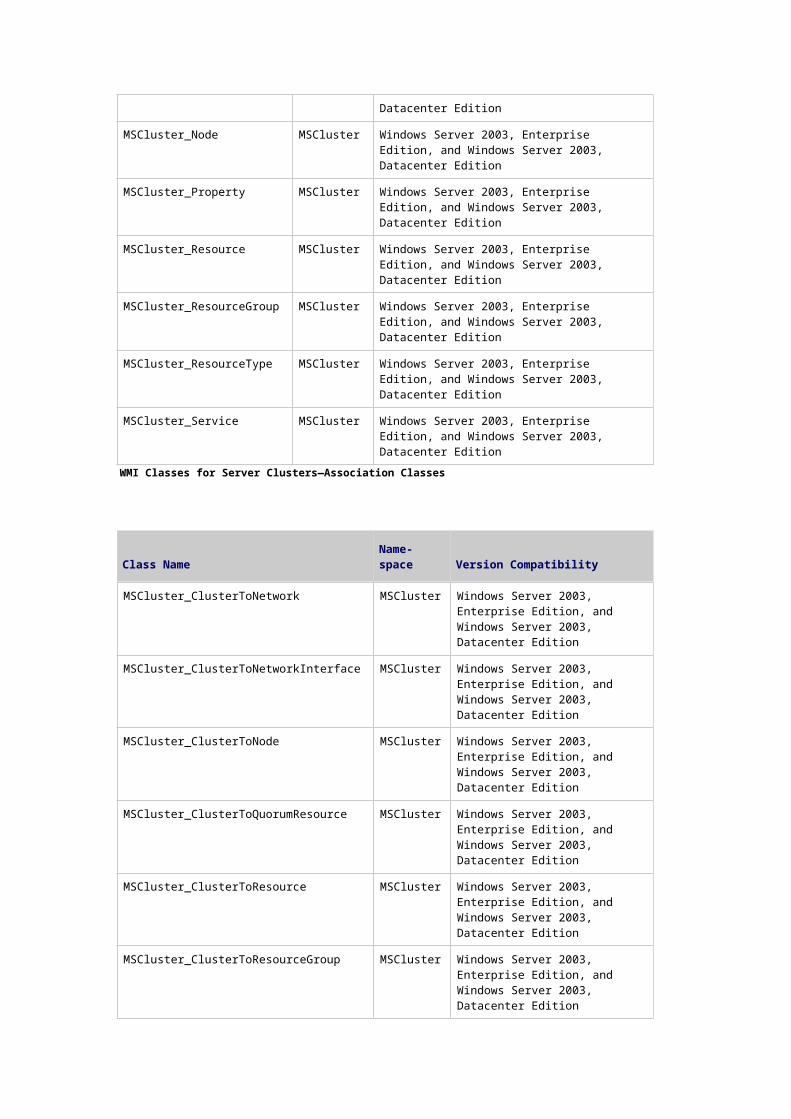
Integrated Clustering Scheme Using Network Load Balancing and Server Clusters
Component Load Balancing
Component Load Balancing is the dynamic load balancing feature of COM+. It enables the creation of
8-node application clusters behind a Component Load Balancing router, enabling the COM+
applications to scale while also ensuring their constant availability. Component Load Balancing is ideal
for stateless COM+ applications. Component Load Balancing is a feature of Microsoft Application
Center 2000. It is not a feature of the Windows Server 2003 family.
Interacting with Other Technologies
Network Load Balancing interacts with the following technologies:
Terminal server clusters
Network Load Balancing can be used to load-balance terminal server clusters. Load balancing pools
the processing resources of several servers using the TCP/IP networking protocol. You can use this
service with a cluster of terminal servers to scale the performance of a single terminal server by
distributing sessions across multiple servers. Session Directory (included in Windows Server 2003,
Enterprise Edition, and Windows Server 2003, Datacenter Edition) keeps track of disconnected
sessions on the cluster, and ensures that users are reconnected to those sessions.
DNS resolution
Network Load Balancing does not support dynamic Domain Name System (DNS) resolution, where the
name of the cluster is automatically registered by the host when the host starts. This functionality
must be disabled on the Network Load Balancing interface for both DNS and Windows Internet Name
Service (WINS); otherwise, each host’s computer name will be registered with the cluster IP address.
When using Network Load Balancing with DNS, you will need to directly configure the DNS server to
register the name. Also, Dynamic Host Configuration Protocol (DHCP) should not be used on the
network interface to which Network Load Balancing is bound; however, DHCP can be used on other
interfaces.
L2TP/IPSec
Network Load Balancing in Windows Server 2003 supports both Point-to-Point Tunneling Protocol
(PPTP) and Layer Two Tunneling Protocol (L2TP) virtual private network (VPN) sessions. However,
Network Load Balancing must be configured in single affinity mode.
Kerberos authentication
Network Load Balancing supports Kerberos with applications it load-balances.
.NET Framework remoting
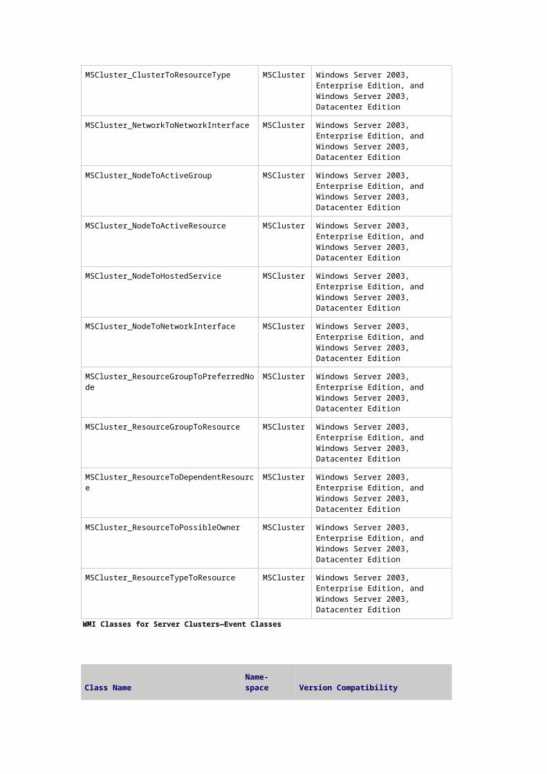
Network Load Balancing supports .NET Framework remoting, which uses method invocations from
client to server over a single TCP connection. This means that once a connection is established, it is
reused for subsequent method invocations and is closed only after the connection remains idle for a
pre-configured amount of time. Network Load Balancing can load-balance these connections, but load
balancing will likely be uneven because it is the TCP connection that is load-balanced and not the
method invocation. Since one client gets “pinned” to a specific server, the load will be well distributed
only if you have many clients connected to the cluster at the same time. Each client will get load-
balanced, but the connection will stay open for a long period of time.
Related Information
The following resource contains additional information that is relevant to this section.
Clustering Technologies
How Network Load Balancing Technology WorksUpdated: March 28, 2003
In this section
Network Load Balancing Terms and Definitions
Network Load Balancing Architecture
Network Load Balancing Protocols
Application Compatibility with Network Load Balancing
Network Load Balancing for Scalability
Scaling Network Load Balancing Clusters
Performance Impact of Network Load Balancing
When Network Load Balancing is installed as a network driver on each of the member servers, or
hosts, in a cluster, the cluster presents a virtual Internet Protocol (IP) address to client requests. The
client requests go to all the hosts in the cluster, but only the host to which a given client request is
mapped accepts and handles the request. All the other hosts drop the request. Depending on the
configuration of each host in the cluster, the statistical mapping algorithm, which is present on all the
cluster hosts, maps the client requests to particular hosts for processing.
Basic Diagram for Network Load Balancing Clusters
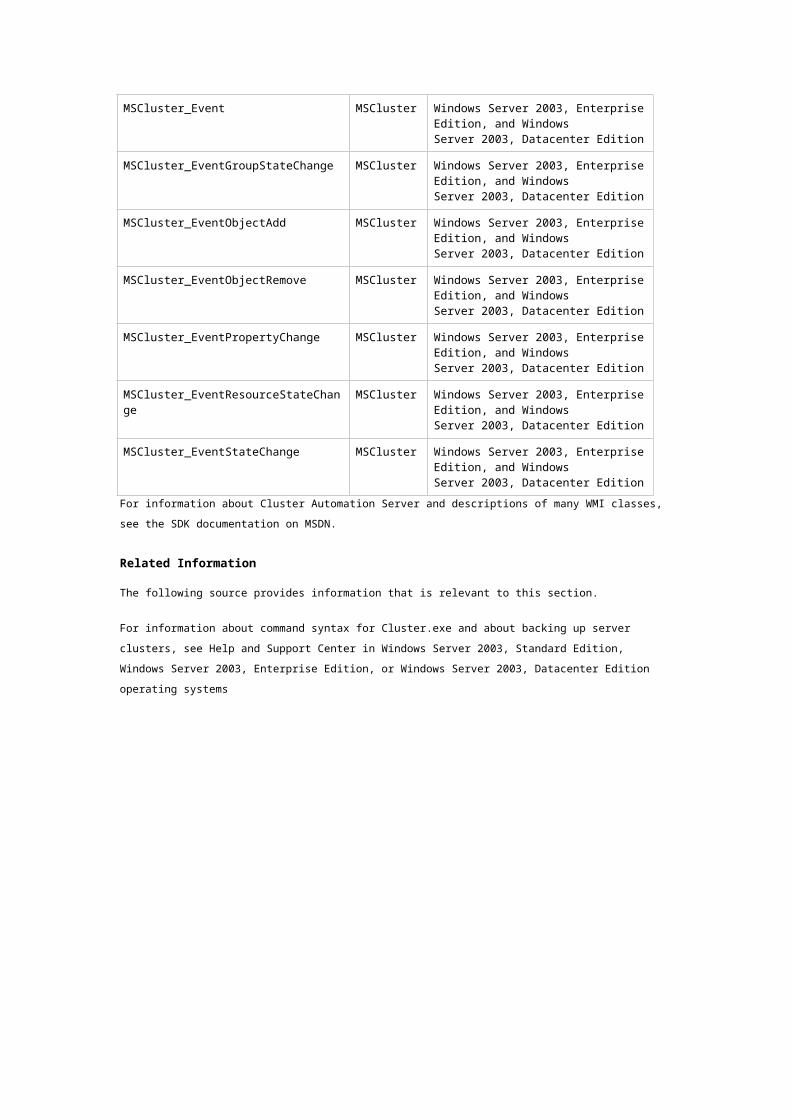
The following figure shows two connected Network Load Balancing clusters. The first cluster is a
firewall cluster with two hosts and the second cluster is a Web server cluster with four hosts.
Two Connected Network Load Balancing Clusters
Network Load Balancing Terms and Definitions
Before you review the Network Load Balancing components and processes, it is helpful to understand
specific terminology. The following terms are used to describe the components and processes of
Network Load Balancing.
affinity
For Network Load Balancing, the method used to associate client requests to cluster hosts. When no
affinity is specified, all network requests are load-balanced across the cluster without respect to their
source. Affinity is implemented by directing all client requests from the same IP address to the same
cluster host.
convergence
The process of stabilizing a system after changes occur in the network. For routing, if a route becomes
unavailable, routers send update messages throughout the network, reestablishing information about
preferred routes.
For Network Load Balancing, a process by which hosts exchange messages to determine a new,
consistent state of the cluster and to elect the default host. During convergence, a new load
distribution is determined for hosts that share the handling of network traffic for specific Transmission
Control Protocol (TCP) or User Datagram Protocol (UDP) ports.
dedicated IP address
The IP address of a Network Load Balancing host used for network traffic that is not associated with
the Network Load Balancing cluster (for example, Telnet access to a specific host within the cluster).
This IP address is used to individually address each host in the cluster and therefore is unique for each
host.
default host
The host with the highest host priority for which a drainstop command is not in progress. After
convergence, the default host handles all of the network traffic for Transmission Control Protocol (TCP)
and User Datagram Protocol (UDP) ports that are not otherwise covered by port rules.
failover
In server clusters, the process of taking resource groups offline on one node and bringing them online
on another node. When failover occurs, all resources within a resource group fail over in a predefined
order; resources that depend on other resources are taken offline before, and are brought back online
after, the resources on which they depend.
heartbeat
A message that is sent at regular intervals by one computer on a Network Load Balancing cluster or
server cluster to another computer within the cluster to detect communication failures.
Network Load Balancing initiates convergence when it fails to receive heartbeat messages from
another host or when it receives a heartbeat message from a new host.
multicast media access control (MAC) address
A type of media access control address used by multiple, networked computers to receive the same
incoming network frames concurrently. Network Load Balancing uses multicast MAC addresses to
efficiently distribute incoming network traffic to cluster hosts.
multihomed computer
A computer that has multiple network adapters or that has been configured with multiple IP addresses
for a single network adapter.
Network Load Balancing supports multihomed servers by allowing multiple virtual IP addresses to be
assigned to the cluster adapter.
throughput
A performance measure defined as the number of client requests processed by a Network Load
Balancing cluster per unit of time.
virtual cluster
A Network Load Balancing cluster that you create by assigning specific port rules to specific virtual IP
addresses. With virtual clusters, you can use different port rules for different Web sites or applications
hosted on the cluster, provided each Web site or application has a different virtual IP address.
virtual IP address
An IP address that is shared among the hosts of a Network Load Balancing cluster. A Network Load
Balancing cluster might also use multiple virtual IP addresses, for example, in a cluster of multihomed
Web servers.
Network Load Balancing Architecture
Network Load Balancing runs as a network driver logically beneath higher-level application protocols,
such as HTTP and FTP. On each cluster host, the driver acts as a filter between the network adapter’s
driver and the TCP/IP stack, allowing a portion of the incoming network traffic to be received by the
host. This is how incoming client requests are partitioned and load-balanced among the cluster hosts.
To maximize throughput and availability, Network Load Balancing uses a fully distributed software
architecture, and an identical copy of the Network Load Balancing driver that runs in parallel on each
cluster host. The figure below shows the implementation of Network Load Balancing as an
intermediate driver in the Windows Server 2003 network stack.
Typical Configuration of a Network Load Balancing Host
The following table describes the principal components related to the Network Load Balancing
architecture.
Components of the Network Load Balancing Architecture
Component Description
Nlb.exe The Network Load Balancing control program. You can use Nlb.exe from the command line to start, stop, and administer Network Load Balancing, as well as to enable and disable ports and to query cluster status.
Nlbmgr.exe The Network Load Balancing Manager control program. Use this command to start Network Load Balancing Manager.
Wlbs.exe The former Network Load Balancing control program. This has been replaced by Nlb.exe. However, you can still use Wlbs.exe rather than Nlb.exe if necessary, for example, if you have existing scripts that reference Wlbs.exe.
Wlbsprov.dll The Network Load Balancing WMI provider.
Nlbmprov.dll The Network Load Balancing Manager WMI provider.
Wlbsctrl.dll The Network Load Balancing API DLL.
Wlbs.sys The Network Load Balancing device driver. Wlbs.sys is loaded onto each host in the cluster and includes the statistical mapping algorithm that the cluster hosts collectively use to determine which host handles each incoming request.
Application and Service Environment
When a Web server application maintains state information about a client session across multiple TCP
connections, it is important that all TCP connections for the client are directed to the same cluster
host.
Network Load Balancing can load-balance any application or service that uses TCP/IP as its network
protocol and is associated with a specific TCP or UDP port. The distributed algorithm, which is used to
determine which host responds to a TCP connection request or incoming UDP packet, can include the
port rule in the decision. Including the port rule in the decision means that for any client, different
members of the Network Load Balancing cluster may service connection requests or packets
addressed to different port rule on the virtual IP address.
Note
While configuring a Network Load Balancing cluster, consider the type of application or
service that the server is providing, and then select the appropriate configuration for Network
Load Balancing hosts.
Client State
A discussion of Network Load Balancing clusters requires clarification of two kinds of client states,
application data state and session state, because they are essential to configuring Network Load
Balancing.
Application data state
In terms of application data, you must consider whether the server application makes changes to the
data store and whether the changes are synchronized across instances of the application (the
instances that are running on the Network Load Balancing cluster hosts). An example of an application
that does not make changes to the data store is a static Web page supported by an IIS server.
Means must be provided to synchronize updates to data state that need to be shared across servers.
One such means is use of a back-end database server that is shared by all instances of the application.
An example would be an Active Server Pages (ASP) page that is supported by an IIS server and that
can access a shared back-end database server, such as a SQL Server.
Session state
Session state (or intraclient state) refers to client data that is visible to a particular client for the
duration of a session. Session state can span multiple TCP connections, which can be either
simultaneous or sequential. Network Load Balancing assists in preserving session state through client
affinity settings. These settings direct all TCP connections from a given client address or class of client
addresses to the same cluster host. This allows session state to be maintained by the server
application in the host memory.
Client/server applications that embed session state within “cookies” or push it to a back-end database
do not need client affinity to be maintained.
An example of an application that requires maintaining session state is an e-commerce application
that maintains a shopping cart for each client.
Network Load Balancing Parameters
By setting port rules, cluster parameters, and host parameters, you gain flexibility in configuring the
cluster, which enables you to customize the cluster according to the various hosts’ capacities and
sources of client requests. Cluster parameters apply to the entire cluster, while the host parameters
apply to a specific host.
Port rules
The Network Load Balancing driver uses port rules that describe which traffic to load-balance and
which traffic to ignore. By default, the Network Load Balancing driver configures all ports for load
balancing. You can modify the configuration of the Network Load Balancing driver that determines how
incoming network traffic is load-balanced on a per-port basis by creating port rules for each group of
ports or individual ports as required. Each port rule configures load balancing for client requests that
use the port or ports covered by the port range parameter. How you load-balance your applications is
mostly defined by how you add or modify port rules, which you create on each host for any particular
port range.
Affinity
Affinity is the method used to associate client requests to cluster hosts. Network Load Balancing
assists in preserving session state through client affinity settings for each port rule that Network Load
Balancing creates. These settings direct all TCP connections from a given client address or class of
client addresses to the same cluster host. Directing the connections to the same cluster host allows
the server applications in the designated host memory to correctly maintain the session state.
Running Network Load Balancing in an Optimal Environment
The sections in this document provide in-depth information about how Network Load Balancing works
in an optimal environment. An optimal environment for Network Load Balancing is defined as follows:
Two or more network adapters in each cluster host are used.
The Transmission Control Protocol/Internet Protocol (TCP/IP) network protocol is the only
protocol used on the cluster adapter. Other protocols, such as Internetwork Packet Exchange
(IPX), should not be added to this adapter.
Within a given cluster, all cluster hosts must operate in either unicast or multicast mode, but
not both.
Network Load Balancing should not be enabled on a computer that is part of a server cluster.
All hosts in a cluster must belong to the same subnet and the cluster’s clients must be able to
access this subnet.
The appropriate hardware resources should be used. The goal in tuning Network Load
Balancing and the applications it load-balances is to determine which hardware resource will
experience the greatest demand, and then to adjust the configuration to relieve that demand
and maximize total throughput.
Cluster parameters, port rules, and host parameters are correctly configured:
Cluster parameters and port rules for each unique virtual IP address are identical
across all hosts. Each unique virtual IP address must be configured with the same port
rules across all hosts that service that virtual IP address. However, if you have multiple
virtual IP addresses configured on a host, each of those virtual IP addresses can have a
different set of port rules.
Port rules are set for all ports used by the load-balanced application. For example,
FTP uses port 20, port 21, and ports 1024–65535.
The dedicated IP address is unique and the cluster IP address is added to each
cluster host.
Network performance should be optimized by limiting switch port flooding.
Windows Internet Name Service (WINS), Dynamic Host Configuration Protocol (DHCP), and
Domain Name System (DNS) services can be run on Network Load Balancing cluster hosts;
however, the interface to which Network Load Balancing is bound cannot use a DHCP address.
Network Load Balancing Driver
The Network Load Balancing driver is installed on a computer configured with Transmission Control
Protocol/Internet Protocol (TCP/IP) and is bound to a single network interface called the cluster
adapter. The driver is configured with a single IP address, the cluster primary IP address, on a single
subnet for all of the member servers (or hosts) on the cluster. Each host has an identical media access
control (MAC) address that allows the hosts to concurrently receive incoming network traffic for the
cluster’s primary IP address (and for additional IP addresses on multihomed hosts).
Incoming client requests are partitioned and load-balanced among the cluster hosts by the Network
Load Balancing driver, which acts as a rule-based filter between the network adapter’s driver and the
TCP/IP stack. Each host receives a designated portion of the incoming network traffic.
Distributed Architecture
Network Load Balancing is a distributed architecture, with an instance of the driver installed on each
cluster host. Throughput is maximized to all cluster hosts by eliminating the need to route incoming
packets to individual cluster hosts, through a process called filtering. Filtering out unwanted packets in
each host improves throughput; this process is faster than routing packets, which involves receiving,
examining, rewriting, and resending the packets.
Another key advantage to the fully distributed architecture of Network Load Balancing is the enhanced
availability resulting from (n-1) way failover in a cluster with n hosts. In contrast, dispatcher-based
solutions create an inherent single point of failure that you must eliminate by using a redundant
dispatcher that provides only one-way failover. Dispatcher-based solutions offer a less robust failover
solution than does a fully distributed architecture.
Load Balancing Algorithm
The Network Load Balancing driver uses a fully distributed filtering algorithm to statistically map
incoming client requests to the cluster hosts, based upon their IP address, port, and other information.
When receiving an incoming packet, all hosts within the cluster simultaneously perform this mapping
to determine which host should handle the packet. Those hosts not required to service the packet
simply discard it. The mapping remains constant unless the number of cluster hosts changes or the
filter processing rules change.
The filtering algorithm is much more efficient in its packet handling than centralized load balancers,
which must modify and retransmit packets. Efficient packet handling allows for a much higher
aggregate bandwidth to be achieved on industry standard hardware.
The distribution of client requests that the statistical mapping function effects is influenced by the
following:
Host priorities
Multicast or unicast mode
Port rules
Affinity
Load percentage distribution
Client IP address
Client port number
Other internal load information
The statistical mapping function does not change the existing distribution of requests unless the
membership of the cluster changes or you adjust the load percentage.
Unicast and Multicast Modes
Network Load Balancing requires at least one network adapter; and different hosts in a cluster can
have a different number of adapters, but all must use the same network IP transmission mode, either
unicast or multicast.
Unicast mode is the default mode, but you can configure the Network Load Balancing driver to operate
in either mode.
When you enable unicast support, the unicast mode changes the cluster adapter’s MAC address to the
cluster MAC address. This cluster address is the same MAC address that is used on all cluster hosts.
When this change is made, clients can no longer address the cluster adapters by their original MAC
addresses.
When you enable multicast support, Network Load Balancing adds a multicast MAC access to the
cluster adapters on all of the cluster hosts. At the same time, the cluster adapters retain their original
MAC addresses.
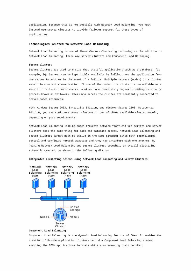
Note
The Network Load Balancing driver does not support a mixed unicast and multicast
environment. All cluster hosts must be either multicast or unicast; otherwise, the cluster will
not function properly.
If clients are accessing a Network Load Balancing cluster through a router when the cluster has been
configured to operate in multicast mode, be sure that the router meets the following requirements:
Accepts an Address Resolution Protocol (ARP) reply that has one MAC address in the payload
of the ARP structure but appears to arrive from a station with another MAC address, as judged
by the Ethernet header.
Accepts an ARP reply that has a multicast MAC address in the payload of the ARP structure.
If your router does not meet these requirements, you can create a static ARP entry in the router. For
example, some routers require a static ARP entry because they do not support the resolution of
unicast IP addresses to multicast MAC addresses.
Subnet and Network Considerations
The Network Load Balancing architecture with a single MAC address for all cluster hosts maximizes use
of the subnet’s hub and/or switch architecture to simultaneously deliver incoming network traffic to all
cluster hosts.
Your network configuration will typically include routers, but may also include layer 2 switches
(collapsed backbone) rather than the simpler hubs or repeaters that are available. Cluster
configuration, when using hubs, is predictable because the hubs distribute IP traffic to all ports.
Note
If client-side network connections at the switch are significantly faster than server-side
connections, incoming traffic can occupy a prohibitively large portion of server-side port
bandwidth.
Network Adapters
Network Load Balancing requires only a single network adapter, but for optimum cluster performance,
you should install a second network adapter on each Network Load Balancing host. In this
configuration, one network adapter handles the network traffic that is addressed to the server as part
of the cluster. The other network adapter carries all of the network traffic that is destined to the server
as an individual computer on the network, including cluster communication between hosts.
Note
Network Load Balancing with a single network adapter can provide full functionality if you
enable multicast support for this adapter.
Selecting an IP Transmission Mode
When you are implementing a Network Load Balancing solution, the Internet Protocol transmission
mode that is selected and the number of network adapters that are required are dependent upon the
following network requirements:
Layer 2 switches or hubs
Peer-to-peer communication between hosts
Maximized communication performance
For example, a cluster supporting a static Hypertext Markup Language (HTML) Web application can
have a requirement to synchronize the Web site copies of a large number of cluster hosts. This
scenario requires interhost peer-to-peer communications. You select the number of network adapters
and the IP communications mode to meet this requirement.
There is no restriction on the number of network adapters, and different hosts can have a different
number of adapters. You can configure Network Load Balancing to use one of four different models.
Single Network Adapter in Unicast Mode
The single network adapter in unicast mode is suitable for a cluster in which you do not require
ordinary network communication among cluster hosts, and in which there is limited dedicated traffic
from outside the cluster subnet to specific cluster hosts. In this model, the computer can also handle
traffic from inside the subnet if the IP datagrams do not carry the same MAC address as the cluster
adapter.
Single Network Adapter in Multicast Mode
This model is suitable for a cluster in which ordinary network communication among cluster hosts is
necessary or desirable, but in which there is limited dedicated traffic from outside the cluster subnet to
specific cluster hosts.
Multiple Network Adapter in Unicast Mode
This model is suitable for a cluster in which ordinary network communication among cluster hosts is
necessary or desirable, and in which there is comparatively heavy dedicated traffic from outside the
cluster subnet to specific cluster hosts.
This mode is the preferred configuration used by most sites because a second network adapter may
enhance overall network performance.
Multiple Network Adapter in Multicast Mode
This model is suitable for a cluster in which ordinary network communication among cluster hosts is
necessary, and in which there is heavy dedicated traffic from outside the cluster subnet to specific
cluster hosts.
Comparison of Modes
The advantages and disadvantages of each model are listed in the following table.
Components of the Network Load Balancing Architecture
Adapter Mode Advantages Disadvantages
Single Unicast Simple configuration Poor overall performance
Single Multicast Medium performance Complex configuration
Multiple Unicast Best balance None
Multiple Multicast Best balance Complex configuration
Network Load Balancing Addressing
The Network Load Balancing cluster is assigned a primary Internet Protocol (IP) address. This IP
address represents a virtual IP address to which all of the cluster hosts respond, and the remote
control program that is provided with Network Load Balancing uses this IP address to identify a target
cluster.
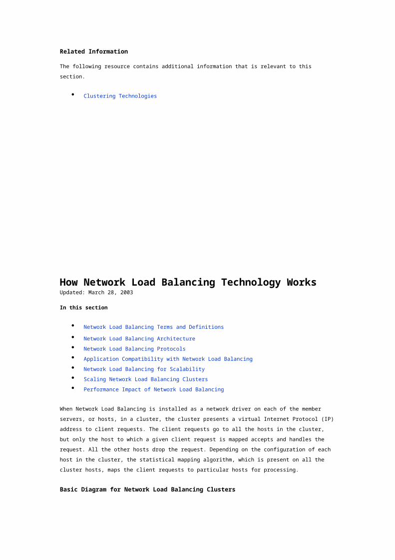
Primary IP address
The primary IP address is the virtual IP address of the cluster and must be set identically for all hosts in
the cluster. You can use the virtual IP address to address the cluster as a whole. The virtual IP address
is also associated with the Internet name that you specify for the cluster.
Dedicated IP address
You can also assign each cluster host a dedicated IP address for network traffic that is designated for
that particular host only. Network Load Balancing never load-balances the traffic for the dedicated IP
addresses, it only load-balances incoming traffic from all IP addresses other than the dedicated IP
address.
The following figure shows how IP addresses are used to respond to client requests.
Network Load Balancing Cluster
Distribution of Cluster Traffic
When the virtual IP address is resolved to the station address (MAC address), this MAC address is
common for all hosts in the cluster. You can enable client connections to only the required cluster host
when more packets are sent. The responding host then substitutes a different MAC address for the
inbound MAC address in the reply traffic. The substitute MAC address is referred to as the Source MAC
address. The following table shows the MAC addresses that will be generated for a cluster adapter.
IP Mode MAC Address Explanation
Unicast inbound 02-BF-W-X-Y-Z W-X-Y-Z = IP address Onboard MAC disabled
Multicast inbound 03-BF-W-X-Y-Z W-X-Y-Z = IP address Onboard MAC enabled
Source outbound 02-P-W-X-Y-A W-X-Y-Z = IP address P = Host priority
In the unicast mode of operation, the Network Load Balancing driver disables the onboard MAC
address for the cluster adapter. You cannot use the dedicated IP address for interhost communications
because all of the hosts have the same MAC address.
In multicast mode of operation, the Network Load Balancing driver supports both the onboard and the
multicast address. If your cluster configuration will require connections from one cluster host to
another, for example, when making a NetBIOS connection to copy files, use multicast mode or install a
second network adapter.
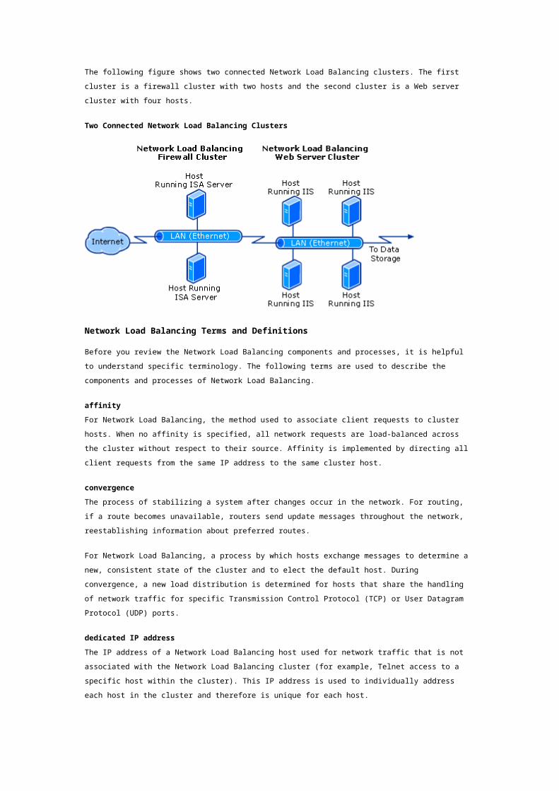
If the cluster hosts were attached to a switch instead of a hub, the use of a common MAC address
would create a conflict because Layer 2 switches expect to see unique source MAC addresses on all
switch ports. To avoid this problem, Network Load Balancing uniquely modifies the source MAC
address for outgoing packets, for example, a cluster MAC address of 02-BF-1-2-3-4 is set to 02-p-1-2-3-
4, where p is the host’s priority within the cluster.
This technique prevents the switch from learning the cluster’s inbound MAC address, and as a result,
incoming packets for the cluster are delivered to all of the switch ports. If the cluster hosts are
connected to a hub instead of to a switch, you can disable masking of the source MAC address in
unicast mode to avoid flooding upstream switches. You disable Network Load Balancing by setting the
Network Load Balancing registry parameter MaskSourceMAC to 0. The use of an upstream level three
switch will also limit switch flooding.
The unicast mode of Network Load Balancing induces switch flooding to simultaneously deliver
incoming network traffic to all of the cluster hosts. Also, when Network Load Balancing uses multicast
mode, switches often flood all of the ports by default to deliver multicast traffic. However, the
multicast mode of Network Load Balancing gives the system administrator the opportunity to limit
switch flooding by configuring a virtual LAN within the switch for the ports corresponding to the cluster
hosts.
Port Rules
Port rules are created for individual ports and for groups of ports that Network Load Balancing requires
for particular applications and services. The filter setting then defines whether the Network Load
Balancing driver will pass or block the traffic.
The Network Load Balancing driver controls the distribution and partitioning of Transmission Control
Protocol (TCP) and User Datagram Protocol (UDP) traffic from connecting clients to selected hosts
within a cluster by passing or blocking the incoming data stream for each host. Network Load
Balancing does not control any incoming IP traffic other than TCP and UDP for ports that a port rule
specifies.
You can add port rules or update parameters by taking each host out of the cluster in turn, updating its
parameters, and then returning it to the cluster. The host joining the cluster handles no traffic until
convergence is complete. The cluster does not converge to a consistent state until all of the hosts
have the same number of rules. For example, if a rule is added, it does not take effect until you have
updated all of the hosts have been updated and they have rejoined the cluster.
Note
Internet Group Membership Protocol (IGMP), ARP, or other IP protocols are passed unchanged
to the TCP/IP protocol software on all of the hosts within the cluster.
Port rules define individual ports or groups of ports for which the driver has a defined action. You need
to consider certain parameters when creating the port rules, such as the:
TCP or UDP port range for which you should apply this rule.
Protocols for which this rule should apply (TCP, UDP, or both).
Filtering mode chosen: multiple hosts, single host, or disabled.
When defining the port rules, it is important that the rules be exactly the same for each host in the
cluster because if a host attempts to join the cluster with a different number of rules from the other
hosts, the cluster will not converge. The rules that you enter for each host in the cluster must have
matching port ranges, protocol types, and filtering modes.
Filtering Modes
The filter defines for each port rule whether the incoming traffic is discarded, handled by only one
host, or distributed across multiple hosts. The three possible filtering modes that you can apply to a
port rule are:
Multiple hosts
With this filtering mode, clusters can equally distribute the load among the hosts or each host can
handle a specified load weight.
Single host
This filtering mode provides fault tolerance for the handling of network traffic with the target host
defined by its priority.
Disabled
This filtering mode lets you build a firewall against unwanted network access to a specific range of
ports; the driver discards the unwanted packets.
Load Weighting
When the filter mode for a port rule is set to multiple hosts, the Load Weight parameter specifies the
percentage of load-balanced network traffic that this host should handle for the associated rule.
Allowed value ranges are from 0 to 100.
Note
To prevent a host from handling any network traffic for a port rule, set the load weight to 0.
Because hosts can dynamically enter or leave the cluster, the sum of the load weights for all cluster
hosts does not have to equal 100. The percentage of host traffic is computed as the local load
percentage value divided by the load weight sum across the cluster.
If you balance the load evenly across all of the hosts with this port rule, you can specify an equal load
distribution parameter instead of specifying a load weight parameter.
Priority
When the filter mode for a port rule is set to single, the priority parameter specifies the local host’s
network traffic for the associated port rule. The host with the highest handling priority for this rule
among the current cluster members will handle all of the traffic.
The allowed values range from 1, the highest priority, to the maximum number of hosts allowed, 32.
This value must be unique for all hosts in the cluster.
Supporting Multiple Client Connections
In a load-balanced multiserver environment, managing and resolving client, application, and session
state for individual clients can be complex. By default, in a Network Load Balancing solution, different
hosts in the cluster can service multiple client connections.
When a client creates an initial connection to a host in the cluster, the application running on this host
holds the client state. If the same host does not service subsequent connections from the client, errors
can occur if the application instances do not share the client state between hosts.
For example, application development for an ASP-based Web site can be more difficult if the
application must share the client state among the multiple hosts in the cluster. If all of the client
connections can be guaranteed to go to the same server, you can solve the difficulties with the
application that is not sharing the client state among host instances.
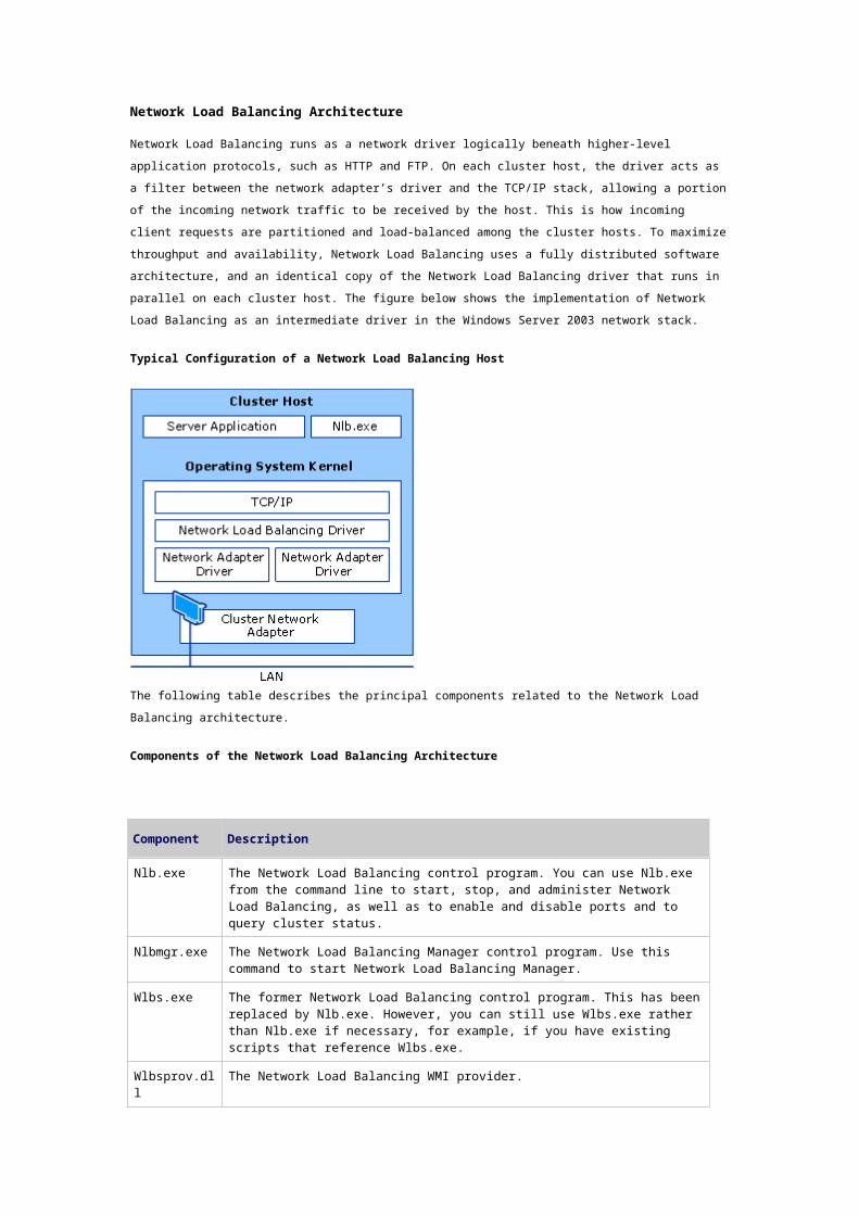
By using a Network Load Balancing feature called affinity, you can ensure that the same cluster host
handles all of the TCP connections from one client IP address. Affinity allows you to scale applications
that manage session state spanning multiple client connections. In a Network Load Balancing cluster,
with affinity enabled, initial client connection requests are distributed according to the cluster
configuration, but after you have established the initial client request the same host will service all of
the subsequent requests from that client.
Affinity
Clients can have many TCP connections to a Network Load Balancing cluster; the load-balancing
algorithm will potentially distribute these connections across multiple hosts in the cluster.
If server applications have client or connection state information, this state information must be made
available on all of the cluster hosts to prevent errors. If you cannot make state information available
on all of the cluster hosts, you cannot use client affinity to direct all of the TCP connections from one
client IP address to the same cluster host. Directing TCP connections from the IP address to the same
host allows an application to maintain state information in the host memory.
For example, if a server application (such as a Web server) maintains state information about a client’s
site navigation status that spans multiple TCP connections, it is critical that all of the TCP connections
for this client state information be directed to the same cluster host to prevent errors.
Affinity defines a relationship between client requests from a single client address or from a Class C
network of clients (where IP addresses range from 192.0.0.1 to 223.255.255.254) and one of the
cluster hosts. Affinity ensures that requests from the specified clients are always handled by the same
host. The relationship lasts until convergence occurs (namely, until the membership of the cluster
changes) or until you change the affinity setting. There is no time-out — the relationship is based only
on the client IP address.
You can distribute incoming client connections based on the algorithm as determined by the following
client affinity settings:
No Affinity
This setting distributes client requests more evenly, when maintaining session state is not an issue,
you can use this setting to speed up response time to requests. For example, because multiple
requests from a particular client can go to more than one cluster host, clients that access Web pages
can get different parts of a page or different pages from different hosts. This setting is used for most
applications.
With this setting, the Network Load Balancing statistical mapping algorithm uses both the port number
and entire IP address of the client to influence the distribution of client requests.
Single Affinity
When single affinity is used, the entire source IP address (but not the port number) is used to
determine the distribution of client requests.
You typically set single affinity for intranet sites that need to maintain session state. This setting
always returns each client’s traffic to the same server, thus assisting the application in maintaining
client sessions and their associated session state.
Note that client sessions that span multiple TCP connections (such as ASP sessions) are maintained as
long as the Network Load Balancing cluster membership does not change. If the membership changes
by adding a new host, the distribution of client requests is recomputed, and you cannot depend on
new TCP connections from existing client sessions ending up at the same server. If a host leaves the
cluster, its clients are partitioned among the remaining cluster hosts when convergence completes,
and other clients are unaffected.
Class C Affinity
When Class C affinity is used, only the upper 24 bits of the client’s IP address are used by the
statistical-mapping algorithm. A Class C unicast IP address ranges from 192.0.0.1 to 223.255.255.254.
The first three octets indicate the network, and the last octet indicates the host on the network.
Network Load Balancing provides optional session support for Class C IP addresses (in addition to
support for single IP addresses) to accommodate clients that make use of multiple proxy servers at the
client site. Class-based IP addressing has been superceded by Classless Interdomain Routing (CIDR).
This option is appropriate for server farms that serve the Internet. Client requests coming over the
Internet might come from clients sitting behind proxy farms. In this case, during a single client session,
client requests can come into the Network Load Balancing cluster from several source IP addresses
during a session.
Class C affinity addresses this issue by directing all the client requests from a particular Class C
network to a single Network Load Balancing host.
There is no guarantee, however, that all of the servers in a proxy farm are on the same Class C
network. If the client’s proxy servers are on different Class C networks, then the affinity relationship
between a client and the server ends when the client sends successive requests from different Class C
network addresses.
Heartbeats and Convergence
Network Load Balancing cluster hosts exchange heartbeat messages to maintain consistent data about
the cluster’s membership. By default, when a host fails to send out heartbeat messages within five
seconds, it is deemed to have failed. Once a host has failed, the remaining hosts in the cluster perform
convergence and do the following:
Establish which hosts are still active members of the cluster.
Elect the host with the highest priority as the new default host.
Ensure that all new client requests are handled by the surviving hosts.
In convergence, surviving hosts look for consistent heartbeats. If the host that failed to send
heartbeats once again provides heartbeats consistently, it rejoins the cluster in the course of
convergence. When a new host attempts to join the cluster, it sends heartbeat messages that also
trigger convergence. After all cluster hosts agree on the current cluster membership, the client load is
redistributed to the remaining hosts, and convergence completes.
The following figure shows how the client load is evenly distributed among four cluster hosts before
convergence takes place:
Network Load Balancing Cluster Before Convergence
The following figure shows a failed host and how the client load is redistributed among the three
remaining hosts after convergence.
Network Load Balancing Cluster After Convergence
Convergence generally only takes a few seconds, so interruption in client service by the cluster is
minimal. During convergence, hosts that are still active continue handling client requests without
affecting existing connections. Convergence ends when all hosts report a consistent view of the cluster
membership and distribution map for several heartbeat periods.
By editing the registry, you can change both the number of missed messages required to start
convergence and the period between heartbeats. However, be aware that making the period between
heartbeats too short increases network overhead on the system. Also be aware that reducing the
number of missed messages increases the risk of erroneous host evictions from the cluster.
Note
Incorrectly editing the registry may severely damage your system. Before making changes to
the registry, you should back up any valued data on the computer.
Network Load Balancing Protocols
Network Load Balancing can load-balance any application or service that uses TCP/IP as its network
protocol and is associated with a specific Transmission Control Protocol (TCP) or User Datagram
Protocol (UDP) port. For applications to work with Network Load Balancing, they must use TCP
connections or UDP data streams.
You can also enable Internet Group Management Protocol (IGMP) support on the cluster hosts to
control switch flooding when operating in multicast mode. IGMP is a protocol used by Internet Protocol
version 4 (IPv4) hosts to report their multicast group memberships to any immediately neighboring
multicast routers.
Application Compatibility with Network Load Balancing
In general, Network Load Balancing can load-balance any application or service that uses TCP/IP as its
network protocol and is associated with a specific TCP or UDP port.
Compatible Applications
Compatible applications must have the following requirements in order to work with Network Load
Balancing:
TCP connections or UDP data streams.
Synchronization of data. If client data that resides on one of the hosts changes as a result of a
client transaction, applications must provide a means of synchronizing data updates if that
data is shared on multiple instances across the cluster.
Single or Class C affinity. If session state is an issue, applications must use single or Class C
affinity or provide a means (such as a client cookie or reference to a back-end database) of
maintaining session state in order to be uniformly accessible across the cluster.
As highlighted in the previous two bullets, before using Network Load Balancing, you must consider an
application’s requirements regarding client state. Network Load balancing can accommodate both
stateless and stateful connections. However, certain factors must be considered for a stateful
connection.
Application servers maintain two kinds of stateful connections:
Interclient state. A state whose data updates must be synchronized with transactions that are
performed for other clients, such as merchandise inventory at an e-commerce site. Because
any host within the cluster can service client traffic, information that must be persistent
across multiple requests or that must be shared among clients needs to be shared in a
location that is accessible from all cluster hosts. Updates to information that is shared among
the hosts needs to be synchronized, for example by using a back-end database server.
Intraclient state. A state that must be maintained for a given client throughout a session (that
can span multiple connections), such as a shopping cart process at an e-commerce site.
Network Load Balancing can be used with applications that maintain either type of state, although
applications requiring interclient state are typically best accommodated with server clusters rather
than Network Load Balancing. While intraclient state can be accommodated through the Network Load
Balancing affinity settings, interclient state, on the other hand, requires additional components outside
of Network Load Balancing.
Interclient State
Some applications require interclient state, that is, the applications make changes to data that must
be synchronized across all instances of the application. For example, any type of application that uses
Microsoft SQL Server for data storage, such as a user registration database, requires interclient state.
When applications do share and change data (require interclient state), the changes need to be
properly synchronized. Each host can use local, independent copies of databases that are merged
offline as necessary. Alternatively, the clustered hosts can share access to a separate, networked
database server.
A combination of these approaches can also be used. For example, static Web pages can be replicated
among all clustered servers to ensure fast access and complete fault tolerance. However, database
requests would be forwarded to a common database server that handles updates for the multiple
cluster hosts.
Network Load Balancing is a viable solution for applications that require interclient state.
Intraclient State
A second kind of state intraclient state (also known as session state), refers to client data that is visible
to a particular client for the duration of a session. Session state can span multiple TCP connections,
which can be either simultaneous or sequential. Network Load Balancing assists in preserving session
state through client affinity settings. These settings direct all TCP connections from a given client
address or group of client addresses to the same cluster host. This allows session state to be
maintained by the server application in the host memory.
Incompatible Applications
Applications that are not compatible with Network Load Balancing have one or more of the following
characteristics:
They bind to actual computer names (examples of such applications are Exchange Server and
Distributed File System).
They have files that must be continuously open for writing (for example, Exchange Server). In
a Network Load Balancing cluster, multiple instances of an application (on different cluster
hosts) should not have a file simultaneously opened for writing unless the application was
designed to synchronize file updates. This is generally not the case.
Network Load Balancing for Scalability
Network Load Balancing scales the performance of a server-based program, such as a Web server, by
distributing its client requests across multiple identical servers within the cluster; you can add more
servers to the cluster as traffic increases. Up to 32 servers are possible in any one cluster. The
following figure represents how additional servers can support more users.
How Servers Scale Out Across a Cluster

You can improve the performance of each individual host in a cluster by adding more or faster CPUs,
network adapters and disks, and in some cases by adding more memory. These additions to the
Network Load Balancing cluster is called scaling up, and requires more intervention and careful
planning than scaling out. Limitations of applications or the operating system configuration could
mean that scaling up by adding more memory may not be as appropriate as scaling out.
You can handle additional IP traffic by simply adding computers to the Network Load Balancing cluster
as necessary. Load balancing, in conjunction with the use of server clusters, is part of a scaling
approach referred to as scaling out. The greater the number of computers involved in the load-
balancing scenario, the higher the throughput of the overall server cluster.
Scaling Network Load Balancing Clusters
Network Load Balancing clusters have a maximum of 32 hosts, and all of the hosts must be on the
same subnet. If a cluster cannot meet the performance requirements of a clustered application, such
as a Web site, because of a host count or subnet throughput limitation, then you can use multiple
clusters to scale out further.
Combining round robin DNS and Network Load Balancing results in a very scalable and highly available
configuration. Configuring multiple Network Load Balancing clusters on different subnets and
configuring DNS to sequentially distribute requests across multiple Network Load Balancing clusters
can evenly distribute the client load that is distributed across several clusters. When multiple Network
Load Balancing Web server clusters are configured with round robin DNS, the Web servers are made
resilient to networking infrastructure failures.
When you use round robin DNS in conjunction with Network Load Balancing clusters, each cluster is
identified in DNS by the cluster virtual IP. Because each cluster is automatically capable of both load
balancing and fault tolerance, each DNS-issued IP address will function until all hosts in that particular
cluster fail. Round robin DNS enables only a limited form of TCP/IP load balancing for IP-based servers
when used without Network Load Balancing. When used with multiple individual hosts, such as Web
servers, round robin DNS does not function effectively as a solution. If a host fails, round robin DNS
continues to route requests to the failed server until the server is removed from DNS.
Performance Impact of Network Load Balancing
The performance impact of Network Load Balancing can be measured in four key areas:
CPU overhead on the cluster hosts, which is the CPU percentage required to analyze and filter
network packets (lower is better).
Response time to clients, which increases with the non-overlapped portion of CPU overhead,
called latency (lower is better).
Throughput to clients, which increases with additional client traffic that the cluster can handle
prior to saturating the cluster hosts (higher is better).
Switch occupancy, which increases with additional client traffic (lower is better) and must not
adversely impact port bandwidth.
In addition, scalability determines how its performance improves as hosts are added to the cluster.
Scalable performance requires that CPU overhead and latency not grow faster than the number of
hosts.
CPU Overhead
All load-balancing solutions require system resources to examine incoming packets and make load-
balancing decisions, and thus impose an overhead on network performance. As previously noted,
dispatcher-based solutions examine, modify, and retransmit packets to particular cluster hosts. (They
usually modify IP addresses to retarget packets from a virtual IP address to a particular host’s IP
address.) In contrast, Network Load Balancing independently delivers incoming packets to all cluster
hosts and applies a filtering algorithm that discards packets on all but the desired host. Filtering
imposes less overhead on packet delivery than re-routing, which results in lower response time and
higher overall throughput.
Throughput and Response Time
Network Load Balancing scales performance by increasing throughput and minimizing response time
to clients. When the capacity of a cluster host is reached, it cannot deliver additional throughput, and
response time grows non-linearly as clients awaiting service encounter queuing delays. Adding another
cluster host enables throughput to continue to climb and reduces queuing delays, which minimizes
response time. As customer demand for throughput continues to increase, more hosts are added until
the network’s subnet becomes saturated. At that point, throughput can be further scaled by using
multiple Network Load Balancing clusters and distributing traffic to them using Round Robin DNS.
Switch Occupancy
The filtering architecture for Network Load Balancing relies on the broadcast subnet of the LAN to
deliver client requests to all cluster hosts simultaneously. In small clusters, this can be achieved using
a hub to interconnect cluster hosts. Each incoming client packet is automatically presented to all
cluster hosts. Larger clusters use a switch to interconnect cluster hosts, and, by default, Network Load
Balancing induces switch-flooding to deliver client requests to all hosts independently. It is important
to ensure that switch-flooding does not use an excessive amount of switch capacity, especially when
the switch is shared with computers outside the cluster. The percentage of switch bandwidth
consumed by flooding of client requests is called its switch occupancy.
Network Load Balancing Tools and SettingsUpdated: March 28, 2003
In this section
Network Load Balancing Tools
Network Load Balancing Registry Entries
Network Load Balancing WMI Classes
Network Port Used by Network Load Balancing
This section provides summary information about the tools, registry entries, WMI classes, and network
ports associated with Network Load Balancing. This information is helpful when evaluating Network
Load Balancing to determine what tools are available to assist in deployment and operations tasks.
Network Load Balancing Tools
The following tools are associated with Network Load Balancing.
NLB.exe command: Network Load Balancing control program
Category
Tool included in the Windows Server 2003 family, Windows 2000 Standard Server SP 3 and later,
Windows 2000 Advanced Server, and Windows 2000 Datacenter Server.
Version compatibility
Available on computers running the Windows Server 2003 family of products, Windows 2000 Advanced
Server, and Windows 2000 Datacenter Server.
The Nlb.exe command replaces Wlbs.exe. Windows NT Load Balancing Service (WLBS) is the former
name of Network Load Balancing in Windows NT Server 4.0. For reasons of backward compatibility,
WLBS continues to be used in certain instances.
You can perform most cluster operations by using the nlb.exe command. Nlb.exe performs the
following functions:
Suspend and resume all cluster operations. The reason you would suspend operations is to
override any remote control commands that might be issued. Resuming cluster operations
would not restart the operations, but would enable use of cluster-control commands, including
remote control commands.
Start and stop cluster operations on the specified hosts.
Disable all new traffic handling on the specified hosts.
Enable and disable traffic handling for the rule whose port range contains the specified port.
Display the current cluster state and the list of host priorities for the current members of the
cluster.
Display information about a given port rule.
Reload the Network Load Balancing driver’s current parameters from the registry.
Display extensive information about the current Network Load Balancing parameters, cluster
state, and past cluster activity. The last several event log records produced by Network Load
Balancing are shown, including the binary data attached to those records. This assists in
technical support and debugging.
Display information about the current Network Load Balancing configuration.
Display the media access control (MAC) address corresponding to the specified cluster name
or IP address.
Nlbmgr.exe: Network Load Balancing Manager
Category
Tool included in the Windows Server 2003 family.
Version compatibility
Available on computers running the Windows Server 2003 family of products, Windows 2000 Advanced
Server, and Windows 2000 Datacenter Server. This tool is also part of the Windows Server 2003
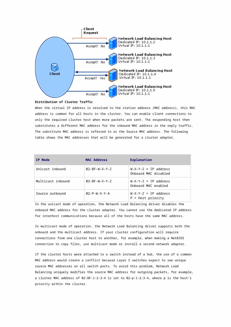
Administration Tools Pack, which you can install on computers running Windows XP Professional. You
can use Network Load Balancing Manager on Windows XP Professional only to manage Network Load
Balancing clusters on remote computers running the Windows Server 2003 family of products. You
cannot install the Network Load Balancing service itself on Windows XP Professional.
Network Load Balancing Manager is used to create and manage Network Load Balancing clusters and
all cluster hosts from a single computer, and you can also replicate the cluster configuration to other
hosts. By centralizing administration tasks, Network Load Balancing Manager helps eliminate many
common configuration errors.
Network Load Balancing Registry Entries
The following registry entries are associated with Network Load Balancing.
The information here is provided as a reference for use in troubleshooting or verifying that the
required settings are applied. It is recommended that you do not directly edit the registry unless there
is no other alternative. Modifications to the registry are not validated by the registry editor or by
Windows before they are applied, and as a result, incorrect values can be stored. This can result in
unrecoverable errors in the system. When possible, use Group Policy or other Windows tools, such as
Microsoft Management Console (MMC), to accomplish tasks rather than editing the registry directly. If
you must edit the registry, use extreme caution.
For more information about the following registry entries, see the Registry Reference in Tools and
Settings Collection.
network adapter ID subkey
The following registry entries are located under HKEY_LOCAL_MACHINE\SYSTEM\CurrentControlSet\
Services\WLBS\Parameters\Interface\network adapter ID subkey.
AliveMsgPeriod
Registry path
HKEY_LOCAL_MACHINE\SYSTEM\CurrentControlSet\Services\WLBS\Parameters\Interface\network
adapter ID subkey
Version
Available in the Windows Server 2003 family, Windows 2000 Advanced Server, and Windows 2000
Datacenter Server.
Modifying this registry entry allows you to control both the message exchange period and the number
of missed messages required to initiate convergence. Modifying the AliveMsgTolerance registry
entry will also allow you to do this. The AliveMsgPeriod value holds the message exchange period in
milliseconds, and the AliveMsgTolerance value specifies how many exchanged messages from a
host can be missed before the cluster initiates convergence.
The values you enter should reflect your installation’s requirements. A longer message exchange
period reduces the heartbeat traffic needed to maintain fault tolerance, but it increases the time that it
takes for Network Load Balancing to stop sending network messages to an offline host. Likewise,
increasing the number of message exchanges prior to convergence reduces the number of
unnecessary convergence initiations due to network congestion, but it too increases the time for an
offline host to stop receiving network traffic.
Using the default values, 5 seconds are needed to discover a missing host, and another 5 seconds are
needed for the cluster to redistribute the load. A total of 10 seconds to stop sending network traffic to
an offline host should be acceptable for most TCP/IP applications. This configuration incurs very low
networking overhead.

Default value: 1000 (1 second)
Possible range: 100–10000
AliveMsgTolerance
Registry path
HKEY_LOCAL_MACHINE\SYSTEM\CurrentControlSet\Services\WLBS\Parameters\Interface\network
adapter ID subkey
Version
Available in the Windows Server 2003 family, Windows 2000 Advanced Server, and Windows 2000
Datacenter Server.
Modifying this registry entry allows you to control both the message exchange period and the number
of missed messages required to initiate convergence. Modifying the AliveMsgPeriod registry entry
will also allow you to do this. For more information, see the previous description for AliveMsgPeriod.
Default value: 5
Possible range: 5–100
DescriptorsPerAlloc
Registry path
HKEY_LOCAL_MACHINE\SYSTEM\CurrentControlSet\Services\WLBS\Parameters\Interface\network
adapter ID subkey
Version
Available in the Windows Server 2003 family, Windows 2000 Advanced Server, and Windows 2000
Datacenter Server.
Determines the number of connection descriptors allocated at a time. Connection descriptors are used
to track TCP connections.
Default value: 512
Possible range: 16–1024
MaskSourceMAC
Registry path
HKEY_LOCAL_MACHINE\SYSTEM\CurrentControlSet\Services\WLBS\Parameters\Interface\network
adapter ID subkey
Version
Available in the Windows Server 2003 family, Windows 2000 Advanced Server, and Windows 2000
Datacenter Server.
Enables masking of the media access control (MAC) address. The MAC address is used for
communication between network adapters on the same subnet. Each network adapter has an
associated MAC address.
If the host is connected to a switch when Network Load Balancing is running in unicast mode, set the
value of MaskSourceMAC to 1 (the default). If the Network Load Balancing host is running in unicast
mode and is attached to a hub that is then connected to a switch, set the value of this entry to 0. If
Network Load Balancing is running in multicast mode, this setting has no effect.
Default value: 1

Possible range: 0–1
MaxDescriptorAllocs
Registry path
HKEY_LOCAL_MACHINE\SYSTEM\CurrentControlSet\Services\WLBS\Parameters\Interface\network
adapter ID subkey
Version
Available in the Windows Server 2003 family, Windows 2000 Advanced Server, and Windows 2000
Datacenter Server.
Determines the maximum number of times the connection descriptors can be allocated. This value
limits the maximum memory footprint of Network Load Balancing.
Default value: 512
Possible range: 1–1024
NetmonAliveMsgs
Registry path
HKEY_LOCAL_MACHINE\SYSTEM\CurrentControlSet\Services\WLBS\Parameters\Interface\network
adapter ID subkey
Version
Available in the Windows Server 2003 family, Windows 2000 Advanced Server, and Windows 2000
Datacenter Server.
Determines whether Network Monitor (NetMon) captures Network Load Balancing heartbeat messages
on the local host.
To allow NetMon to capture Network Load Balancing heartbeat messages on the local host, set the
value of this entry to 1. To get the best performance, leave the value of this entry at its default value
of 0.
NumActions
Registry path
HKEY_LOCAL_MACHINE\SYSTEM\CurrentControlSet\Services\WLBS\Parameters\Interface\network
adapter ID subkey
Version
Available in the Windows Server 2003 family, Windows 2000 Advanced Server, and Windows 2000
Datacenter Server.
This key is an internal Network Load Balancing entry. Increase the value of this entry only if you
encounter an event log message that advises you to do so.
Default value: 100
Possible range: 5–500
NumAliveMsgs
Registry path
HKEY_LOCAL_MACHINE\SYSTEM\CurrentControlSet\Services\WLBS\Parameters\Interface\network
adapter ID subkey
Version
Available in the Windows Server 2003 family, Windows 2000 Advanced Server, and Windows 2000
Datacenter Server.
This is an internal Network Load Balancing entry. Increase the value of this entry only if you encounter
an event log message that advises you to do so.
Default value: 66
Possible range: 5–500
NumPackets
Registry path
HKEY_LOCAL_MACHINE\SYSTEM\CurrentControlSet\Services\WLBS\Parameters\Interface\network
adapter ID subkey
Version
Available in the Windows Server 2003 family, Windows 2000 Advanced Server, and Windows 2000
Datacenter Server.
This is an internal Network Load Balancing entry. Increase the value of this entry only if you encounter
an event log message that advises you to do so.
Default value: 200
Possible range: 5–500
RemoteControlUDPPort
Registry path
HKEY_LOCAL_MACHINE\SYSTEM\CurrentControlSet\Services\WLBS\Parameters\Interface\network
adapter ID subkey
Version
Available in the Windows Server 2003 family, Windows 2000 Advanced Server, and Windows 2000
Datacenter Server.
Determines the UDP port that is used by Network Load Balancing to receive remote control messages.
Note that for backwards compatibility, Network Load Balancing automatically listens to port 1717. If
you decide to firewall the remote control port to block remote control messages, you also always need
to firewall port 1717.
Do not use ports that are commonly used for other purposes (such as those used for FTP or DNS).
Default value: 2504
Note
DecriptorsPerAlloc, MaxDescriptorAllocs, NumActions, NumPackets, and NumAliveMsgs only
take effect when the Network Load Balancing driver is binding to the network adapter (upon
restarting the hosts, or through disabling and then re-enabling the network adapter). The
remaining settings will take effect when the Network Load Balancing driver binds to the
network adapter, or when Network Load Balancing is reloaded (using Nlb.exe reload
command).
Network Load Balancing WMI Classes

The following table lists and describes the WMI classes that are associated with Network Load
Balancing.
WMI Classes Associated with Network Load Balancing
Class Name Namespace Version Compatibility
MicrosoftNLB_Cluster root\cimv2 Included in Windows Server 2003, Windows 2000 Advanced Server, and Windows 2000 Datacenter Server
MicrosoftNLB_ClusterClusterSetting root\cimv2 Included in Windows Server 2003, Windows 2000 Advanced Server, and Windows 2000 Datacenter Server
MicrosoftNLB_ClusterSetting root\cimv2 Included in Windows Server 2003, Windows 2000 Advanced Server, and Windows 2000 Datacenter Server
MicrosoftNLB_ExtendedStatus root\cimv2 Included in Windows Server 2003, Windows 2000 Advanced Server, and Windows 2000 Datacenter Server
MicrosoftNLB_Node root\cimv2 Included in Windows Server 2003, Windows 2000 Advanced Server, and Windows 2000 Datacenter Server
MicrosoftNLB_NodeNodeSetting root\cimv2 Included in Windows Server 2003, Windows 2000 Advanced Server, and Windows 2000 Datacenter Server
MicrosoftNLB_NodeSetting root\cimv2 Included in Windows Server 2003, Windows 2000 Advanced Server, and Windows 2000 Datacenter Server
MicrosoftNLB_NodeSettingPortRule root\cimv2 Included in Windows Server 2003, Windows 2000 Advanced Server, and Windows 2000 Datacenter Server
MicrosoftNLB_ParticipatingNode root\cimv2 Included in Windows Server 2003, Windows 2000 Advanced Server, and Windows 2000 Datacenter Server
MicrosoftNLB_PortRule root\cimv2 Included in Windows Server 2003, Windows 2000 Advanced Server, and Windows 2000 Datacenter Server
MicrosoftNLB_PortRuleDisabled root\cimv2 Included in Windows Server 2003, Windows 2000 Advanced Server, and Windows 2000 Datacenter Server
MicrosoftNLB_PortRuleFailover root\cimv2 Included in Windows Server 2003, Windows 2000 Advanced Server, and Windows 2000 Datacenter Server
MicrosoftNLB_PortRuleLoadBalanced
root\cimv2 Included in Windows Server 2003, Windows 2000 Advanced Server, and Windows 2000 Datacenter Server
For more information about these WMI classes, see the WMI SDK documentation on MSDN.
Network Port Used by Network Load Balancing
Network Load Balancing uses the following network port.
Network Ports Used by Network Load Balancing
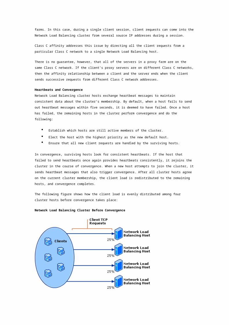
Service Name UDP
NLBS 2504
Port numbers in a range of 0 to 65,535 are currently supported by Network Load Balancing for
TCP/UDP. The default port range is 0 to 65,535. To load-balance all client requests with a single port
rule, use the default port range. By using the default port range, you do not have to worry about which
port or ports are associated with the application whose client requests you are load-balancing.