city of cold lake construction standards revisions page …
TRANSCRIPT

City of Cold Lake CONSTRUCTION STANDARDS REVISIONS Page 1 of 1
SECTION CLAUSE/DRAWING NUMBER DATE OF REVISION
Section 02311
Site Grading
Clause 3.1 – Compaction
Clause 3.11 – Common Excavation July 2017
Section 02315
Trench Excavation, Backfill and
Compaction
Clause 1.2 – Definitions July 2017
Section 02317
Roadway Excavation, Backfill and
Subgrade Preparation
Clause 3.14 - Embankments July 2017

CITY OF COLD LAKE
2017
STANDARD CONSTRUCTION SPECIFICATIONS

City of STANDARD CONSTRUCTION SPECIFICATIONS
Cold Lake TABLE OF CONTENTS Page 1 of 2
DIVISION 1 GENERAL REQUIRMENTS
Section 01015 Contract Administration
Section 01040 Project Coordination
Section 01301 Submittals
Section 01310 Construction Schedule
Section 01400 Quality Control
Section 01501 Temporary Work
Section 01545 Safety Requirements
Section 01561 Regulatory Requirements and Environmental Protection
Section 01562 Archaeology, Antiques and Relics
Section 01570 Traffic Control
Section 01601 Material and Equipment
Section 01770 Take Over Procedures
DIVISION 2 SITE WORK
Section 02225 Site Work Demolition and Removal
Section 02231 Clearing and Grubbing
Section 02311 Site Grading
Section 02315 Trench Excavation, Backfill and Compaction
Section 02317 Roadway Excavation, Backfill and Compaction
Section 02321 Hauling and Haul Roads
Section 02336 Reshaping Roadway Subgrade
Section 02342 Geotextiles
Section 02344 Soil Insulation
Section 02362 Calcium Chloride Dust Control
Section 02371 Rip Rap
Section 02372 Gabions
Section 02445 Boring or Jacking Conduits
Section 02511 Water Mains
Section 02530 Sanitary Sewer Mains
Section 02531 Sanitary and Storm Sewer Force Mains
Section 02560 Storm Sewer Mains
Section 02562 Catch Basin Leads
Section 02563 Manholes and Catch Basins
Section 02564 Water, Sanitary and Storm Sewer Service Connection
Section 02565 Adjustment of Manholes, Catch Basins, Hydrants and Water Valves
Section 02566 Connections to Existing Mains
Section 02581 Concrete Encased Duct Banks and Manholes
Section 02582 Direct Buried Underground Cable Ducts
Section 02586 Underground Cable Ducts for Road Crossings
Section 02610 Corrugated Steel Pipe Culverts
Section 02620 Sub drain Systems
Section 02721 Granular Sub base
Section 02723 Granular Base
Section 02741 Hot Mix Asphaltic Paving
Section 02742 Hot Mix Asphalt Pavement
Section 02745 Asphalt Prime Coat
Section 02747 Asphaltic Concrete Curbs
Section 02748 Reshaping Granular Roadbed
Section 02760 Pavement Marking General
Section 02761 Painted Pavement Markings

City of STANDARD CONSTRUCTION SPECIFICATIONS
Cold Lake TABLE OF CONTENTS Page 2 of 2
Section 02762 Thermoplastic Pavement Markings
Section 02763 Spray Plastic Pavement Markings
Section 02764 Cold Plastic Pavement Markings
Section 02767 Pavement Marking Removal
Section 02770 Concrete Curbs & Gutters, Sidewalks, Medians and Drainage Swales
Section 02780 Precast Concrete Paving Stone
Section 02785 Chip Seal Coat
Section 02786 Asphalt Concrete Overlay Paving
Section 02821 Chain Link Fences and Gates
Section 02822 Wire Fences and Gates
Section 02823 Post and Cable Fence
Section 02833 Interlocking Block Retaining Wall
Section 02844 Steel W-beam Guide Wall
Section 02845 Concrete Barriers
Section 02847 Precast Concrete Curbs
Section 02890 Temporary Construction Signing
Section 02891 Roadway Signs
Section 02901 Tree and Shrub Preservation
Section 02906 Planting of Trees, Shrubs and Ground Covers
Section 02911 Topsoil Placement and Finish Grading
Section 02921 Seeding
Section 02922 Hydraulic Seeding
Section 02923 Sodding
Section 02936 Tree Pruning
Section 02955 Relining Underground Pipelines
Section 02961 Asphalt Concrete Pavement Milling
Section 02965 Hot in Place Asphalt Recycling
Section 02982 Routing and Sealing Pavement Cracks
Section 02983 Pavement Crack Cleaning and Filling
Section 02985 Removal and Replacement of Existing Concrete Work
DIVISION 3 CONCRETE
Section 03050 Basic Concrete Materials and Test Methods
Section 03100 Concrete Formwork
Section 03200 Concrete Reinforcement
Section 03300 Cast in Place Concrete
Section 03370 Slip Formed Concrete
DIVISION 16 ELECTRICAL
Section 16010 Electrical General Requirements
Section 16050 Basic Electrical Products and Materials
City of GENERAL REQUIREMENTS Division 1
Cold Lake TABLE OF CONTENTS Page 1 of 1
Section 01015 Contract Administration
Section 01040 Project Coordination
Section 01301 Submittals
Section 01310 Construction Schedule
Section 01400 Quality control
Section 01501 Temporary Work
Section 01545 Safety Requirements
Section 01561 Regulatory Requirement and Environmental Protection
Section 01562 Archaeology, Antiques and Relics
Section 01570 Traffic Control
Section 01601 Material and Equipment
Section 01770 Take Over Procedures

City of CONTRACT ADMINISTRATION Section 01015
Cold Lake Page 1 of 4
1. GENERAL
This section includes information regarding the following:
Contingency Allowances
Procedures Applicable to Alternatives
Metric Standards
Measurement and Payment, including payment clauses for:
.1 Mobilization and Demobilization
.2 Traffic Accommodation
1.1 Related Sections
.1 Instruction to Bidders Section 00200
.2 General Conditions Section 00700
1.2 Contingency Allowance
.1 The disposition of Contingency Allowances is detailed in Section 00700 – General Conditions,
Article 48.
.2 Do not include in the Contract Price, additional sums for products, installation, overhead or profit.
.3 Expenditures under the contingency allowance will be authorized in accordance with the procedures
provided in Section 00700 – General Conditions, Article 45 – Changes in Work and evaluated as
detailed in Article 46 – Valuation of Changes.
1.3 Alternatives
.1 General
.1 The Contract is based on the materials, equipment and methods described in the Contract
Documents.
.2 The Engineer will consider proposals for substitution of material, equipment and methods
only when such proposals are accompanied by full and complete technical data and all other
information required by the Engineer to evaluate the proposed substitutions.
.2 Approval of Alternatives
.1 The Engineer shall be the sole judge as to the merits of proposed alternative and their
acceptance.
.2 Do not substitute material, equipment or methods unless the Engineer has specifically
approved such substitution for this work.

City of CONTRACT ADMINISTRATION Section 01015
Cold Lake Page 2 of 4
.3 Alternative will be consider on the basis of the following:
.1 Savings in cost.
.2 Improvement in quality.
.3 Compatibility with other components.
.4 Aesthetics.
.5 Increase in speed of construction.
.3 Or Equal
.1 Whatever the terms “or equivalent”, “or equal”, “or approved equal” appears after specific
types of materials and items shown on the drawings or specified, they shall be construed to
mean as being equal in the opinion of the Engineer, in material content, workmanship and
quality to that designated as being the minimum acceptable standard and that this written
approval must be obtained for proposed alternatives.
.4 Use of Alternatives
.1 If the Contractor elects to supply and/or install an alternative material to that specified or
shown on the drawings, the Contractor shall be responsible for making all consequent
adjustments at this own cost to make the alternative fit into the work as specified and these
consequent costs shall be deemed to be included in the price bid for the alternate. The
Contractor shall be responsible for any costs incurred by the Engineer for changes to the
drawings or specifications as a result of any substitutions.
2. METRIC
These specifications are metric and metric usage is based upon SI units in accordance with CSA Standard
CAN3Z234.7-75-Canadian Metric Practice Guide.
3. MEASUREMENTS AND PAYMENT
3.1 Quantity Measurements
.1 The Engineer will compute quantities of work performed monthly on the basis of measurements
taken by the Engineer.
.2 The Engineer will submit said quantities to the contractor for his review.
3.2 Progress Payments
.1 The issuance of a certificate for payment by the Engineer will constitute a representation to the
Owner that to the best of the Engineer’s knowledge, information and belief, the Work has progressed
to the point indicated (subject to an evaluation of the Work for general conformance with the
Contract Documents upon completion, to the results of any subsequent tests called for in the Contract
Documents, to the correction of any defects in the Work not observed or discovered by the Engineer
nor pointed out to the correctable prior to completion and to any qualifications stated in the
Engineer’s certificate for payment) and that the Contractor is entitled to payment in the amount
certified. By issuing a certificate for payment, the Engineer shall not thereby be deemed to

City of CONTRACT ADMINISTRATION Section 01015
Cold Lake Page 3 of 4
represent that it has made exhaustive or continuous on site inspection means, methods,
techniques, sequences or procedures or that is has made any examination to determine how
or for what purposes the Contractor or the Subcontractors have used the money paid on
account of the Contract Price.
.2 The Contractor’s obligation to perform and complete the Work in accordance with the
Contract Documents shall be absolute. Neither the recommendation or certification of any
progress or final payment by the Engineer, nor the issuance of any certificate for payment,
nor any payment by the owner to the Contractor under the Contract Documents, nor any use
or occupancy of the Work or any part thereof by the Owner nor any act of acceptance by the
Owner nor any failure to do so, nor any correction of defective Work by the Owner shall
constitute an acceptance of work or products which are not in accordance with the Contract
Documents or a release of the Contractor’s obligation to perform the Work in accordance
with the Contract Documents.
3.3 Bonding and Insurance Costs
.1 Where Mobilization and Demobilization is included as a bid item, any costs associated with the
provision of bonding and insurance shall be included in the lump sum price bid for mobilization.
.2 No direct payment will be made for the recovery of bonding and insurance costs if there is no bid
item for Mobilization and Demobilization.
3.4 Mobilization and Demobilization Payment Clause
.1 Where Mobilization and Demobilization is included a s a bid item, it shall consist of the necessary
work and operations including, but not limited to the movement of personnel, equipment, supplies
and incidentals to the work, the establishment of offices and other facilities necessary to undertake
the work. It will also be compensation for expenses incurred for other work and operations that must
be performed prior to the commencement of the work.
.2 The Owner will pay for Mobilization and Demobilization at the lump sum price bid for
“Mobilization and Demobilization” which payment shall be compensation in full for all costs
associated with Tender submission, tender and mobilization and demobilization.
.3 The initial payment by the owner will be as follows:
.1 Where the Lump Sum tender amount for Mobilization and Demobilization is less than or
equal to 10% of the original Total Tender Amount, the Owner will pay 60% of the Lump
Sum bid for Mobilization and Demobilization.
.2 Where the Lump Sum tender amount for Mobilization and Demobilization is exceeds 10% of
the original Total Tender Amount, the owner will pay 60% of an amount equal to 10% of the
Total Tender Amount.
The outstanding balance, in either case, will be paid upon construction completion.
.4 Initial payment for Mobilization and Demobilization will not be made until value of the work
completed on bid items, other than Mobilization and Demobilization, exceeds 10% of the total tender
amount.

City of CONTRACT ADMINISTRATION Section 01015
Cold Lake Page 4 of 4
.5 Mobilization and Demobilization will be paid only once, regardless of the number of times the
Contractor mobilizes.
.6 No direct payment will be made for Mobilization and Demobilization if there is no bid item for it.
3.5 Traffic Accommodation Payment Clause
.1 Where Traffic Accommodation is included as a bid item, it shall consist of the necessary work and
operation, including but not limited to controlling the movement of traffic and pedestrians, supply
and maintenance of temporary signing and other incidentals necessary for the Work.
.2 The Owner will pay for Traffic Accommodation at the lump sum price bid for “Traffic
Accommodation”, which payment shall be compensation in full for all costs associated with Traffic
Accommodation.
.3 The initial payment by the Owner will be as follows:
.1 Where the Lump Sum tender amount for Traffic Accommodation is less than or equal to
10% of the original Total Tender Amount, the Owner will pay 60% of the Lump Sum bid for
Traffic Accommodation.
.2 Where the Lump Sum Tender amount for Traffic Accommodation exceeds 10% of the
original Total Tender amount, the owner will pay 60% of an amount equal to 10% of the
total tender amount.
The outstanding balance, in either case, will be paid upon construction completion.
.4 Traffic Accommodation will be paid only once, regardless of the number of times the Contractor
adjusts the traffic accommodations.
.5 No direct payment will be made for Traffic Accommodation if there is no bid item for it.

City of PROJECT COORDINATION Section 01040
Cold Lake Page 1 of 4
1. GENERAL
This section includes requirements for project meetings, project coordination, cutting and patching, and field
engineering.
1.1 Related Sections
.1 Material and Equipment Section 01601.
.2 Individual product sections: Cutting and Patching incidental to work of the section. Advance
notification to other sections required.
1.2 Meetings
.1 Pre construction meeting
.1 A pre construction meeting will be arranged by the engineer after the contract is awarded.
.2 Meetings will be held at the engineer’s office or at an alternate location at or near the site.
.2 Progress meetings
.1 Progress meetings will be held on a regular bi weekly basis or more frequently if requested
by the Engineer.
.2 Accommodation for progress meeting shall be provided by the Contractor at or near the site.
.3 The Engineer will give to all parties advance notice of meeting dates, times and locations.
.4 The Contractor shall have in attendance the Superintendent and if requested by the Engineer,
representative of the Subcontractors.
.5 The Engineer will have the Project Engineer and/or the Resident Engineer in attendance.
.6 The Owner may have a representative in attendance.
.7 Minutes will be taken by the Engineer and copies will be distributed to attendees within five
(5) business days of the meeting date.
1.3 Coordination
.1 General
.1 Although the specifications set forth the work of various trades under separate divisions, it is
not intended that the work of that trade is necessarily limited to, nor is inclusive of all work
set forth in that particular division. The Contractor shall delegate the extent of the work of
various trades and shall coordinate the work of all trades.
.2 Although the specifications are separated into titled division, the Engineer will not be an
arbitrator to establish limits of any contracts between the Contractor and its Subcontractors.

City of PROJECT COORDINATION Section 01040
Cold Lake Page 2 of 4
.2 Work by Others
.1 The Contractor shall coordinate the work for this Contract with the work of all other
contractors, utility companies and work forces.
.3 Existing Utilities
The contractor shall be responsible for notifying the appropriate City Departments and utility
companies of his intention to carry out operations in the vicinity of any existing main, line, conduit
or other structure or utility, treed and/or natural feature, at least two weeks in advance of any such
operations being carried out. The Contractor shall arrange a site meeting with the Engineer and one
representative of any City Department or utility company requiring relocation or new installation
during construction. The following is a list of utility agencies commonly involved in the Cold Lake
Area:
.1 In the case of water, sanitary and storm sewer lines:
City of Cold Lake
Public Works Department
780-639-4566
.2 In the case of overhead or underground telephone or telecommunication lines:
Telus Communications Inc
1-800-815-5715
.3 In the case of overhead or underground electric power lines and street lighting:
Atco Electric
1-800-668-2248
780-826-6708
.4 In the case of overhead or underground cable TV:
Northern Cablevision
780-465-3489
.5 In the case of underground natural gas pipeline:
ATCO Gas
310-5678
780-594-5330
.6 In the case of trees and/or natural features:
City of Cold Lake
Public Works Department
780-639-4566
.7 For locations of underground utilities and pipelines:
Alberta One Call
1-800-242-3447
.8 In the case of traffic signal controllers and signal loops:
City of Cold Lake
Public Works Department
780-639-4566
City of PROJECT COORDINATION Section 01040
Cold Lake Page 3 of 4
.9 In the case of oil and natural gas pipelines:
Alberta Energy and Utilities Board
Bonnyville Field Centre PO Box 5169
Northlands Development Building
209, 4901 - 50th Avenue
Bonnyville, AB T9N 2G4
Phone: 780.826.5352* Fax: 780.826.2366
Email: [email protected]
(*To call toll-free, dial 310.0000)
.10 The Contractor shall, at his expense, conduct his operations in accordance with the
requirements of the utility authorities having jurisdiction.
1.4 Cutting and Patching
.1 The Contractor shall do all cutting, fitting or patching of his work that may be required to make its
several parts come together properly and fit it to receive or to be received by work of Other
Contractors shown in or reasonably implied by the Contract Documents.
.2 Any cost caused by ill timed work shall be borne by the Contractor.
.3 The Contractor shall not endanger any existing work by cutting, digging, or any other method and
shall not cut or alter any work without the consent of the Engineer.
1.5 Field Engineering
.1 Surveys – General
.1 The Engineer will establish bench marks and monuments and be responsible for their
accuracy.
.2 The Contractor shall safeguard all survey control marks, statutory iron posts, and legal lot
corner posts, property pins and shall re establish at his expense, all survey control marks
statutory iron posts and legal lot corner posts and property pins, removed without
authorization from the Engineer.
.2 Datum Planes
.1 Elevations indicated or specified refer to Geodetic datum unless otherwise stated.
.3 Setting Out
.1 The Contractor shall remove physical obstructions as necessary for the survey crew
operation and arrange a survey work schedule with engineer 48 hours prior to requiring
completion of survey work.
.2 The Engineer will establish base lines, control points, lines and grades for work and may
check points, lines or grades established by Contractor.
.3 The contractor shall be responsible for the accuracy of his work in relation to the Engineer’s
bench marks and monuments.

City of PROJECT COORDINATION Section 01040
Cold Lake Page 4 of 4
.4 Assistance to Resident Engineer
.1 The Engineer may require temporary assistance in performing surveys periodically
throughout the duration of the project. The Contractor shall make available upon request of
the Engineer a temporary assistant at no additional cost.

City of SUBMITTALS Section 01301
Cold Lake Page 1 of 3
1. GENERAL
This section includes submissions of shop drawings, product data and samples.
1.1 Related sections
.1 Quality Control Section 01400
1.2 Administrative
.1 Submit to Engineer submittals listed for review. Submit with reasonable promptness and in orderly
sequence so as to not cause delay in the Work.
.2 Work affected by the submittal shall not proceed until review is complete.
.3 Review submittals prior to submission to the Engineer. Submittals not stamped, signed, dated and
identified will be returned without being examined and shall be considered rejected.
.4 Contractors responsibility for deviations in submission from requirements of Contract Documents is
not relieved by Engineers review.
1.3 Shop Drawings, Samples, Mix Design and Product Data
.1 Shop Drawings and Samples
.1 All shop drawings shall be accurately drawn to a scale sufficiently large to show all pertinent
features of the item and its method of connection to the Work.
.2 Unless otherwise specifically directed by the Engineer, shop drawing prints shall be made in
blue or black line on white background.
.3 The Contractor shall submit three copies of all shop drawings.
.4 The Contractor shall review, stamp with its approval and submit, with reasonable promptness
and in orderly sequence so as to cause no delay in the Work or in the work of any Other
Contractor, all Shop Drawings, Product Data and Samples required by the contract document
or as requested by the Engineer. Shop Drawings, Product data and samples shall be properly
identified and shall be in the form specified or as the Engineer may require. At the time of
submission, the contractor shall inform the Engineer in writing of any deviation in the Shop
Drawings, Product Data or Samples from the requirements of the contract documents. Shop
Drawings which require approval of any legally constituted authority having jurisdiction
shall be submitted to such authority by the Contractor for approval.
.5 By approving and submitting shop drawings, Product Data and Samples, the Contractor
thereby represents that it determined and verified all field measurements, field construction
criteria, materials, catalogue numbers and similar data, or will d so, and that it has checked
and coordinated all Shop Drawings, Product Data and Samples with the requirements of the
Work and of the Contract Documents.
.6 The Engineer will review the Shop Drawings, Product data and samples with reasonable
promptness, but only for general conformance with the Contract Documents. The Engineer’s

City of SUBMITTALS Section 01301
Cold Lake Page 2 of 3
review of a separate item shall not indicate approval of such item or of any assembly in
which the item functions. The Engineer’s review of Shop Drawings Product Data or Samples
shall not relieve the contractor of the responsibility for any deviation from the requirements
of the Contract Documents unless the Contractor has informed the Engineer in writing of
such deviation at the time of submission and the Engineer has given written approval to the
specific deviation: provided that any such review and approval by the Engineer shall not
relieve the Contractor from responsibility for errors or omissions in the Shop Drawings,
samples themselves.
.7 The Contractor shall make any corrections required by the Engineer and shall resubmit the
required number of corrected copies of Shop Drawings, Product Data or New Samples. The
Contractor shall direct specific attention in writing or on resubmitted Shop Drawings to
revisions other than the corrections requested by the Engineer on previous submissions.
.2 Mix Designs
.1 Mix design are required or specified in other Sections of the Specifications.
.2 All mix designs shall be completed by an independent materials testing agency approved by
the Engineer.
.3 Mix designs to be submitted at least three weeks prior to commencing work.
.3 Colors
.1 Unless the precise color and pattern is specifically described in the Contract Documents,
whenever a choice of color or pattern is available in a specified product, the Contractor shall
submit accurate color charts and pattern charts to the Engineer for his review and selection.
.4 Identification of Submittals
.1 The Contractor shall completely identify each submittal and re-submittal by showing at least
the following information:
.1 Name and address of Contract and Contractor plus name and telephone number of
the individual who may be contracted for further information.
.2 Project name, Drawing Number and Specifications Section Number to which the
submittal applies.
.3 Identify original submittals or re-submittals.
.5 Coordination of Submittals
.1 Prior to submittal for Engineer’s review, the Contractor shall use all means necessary to fully
coordinate all material, including the following procedures:
.1 Determine and verify all field dimensions and conditions, material, catalogue
numbers and similar data.
.2 Coordinate as required with all trades and with all public agencies involved.

City of SUBMITTALS Section 01301
Cold Lake Page 3 of 3
.3 Secure all necessary approvals from public agencies and others and signify by stamp
. or other means that they have been secured.
.4 Clearly indicate all deviations for the Contract Documents.
.6 Timing of Submittals
.1 The Contractor shall make all submittals far enough in advance of scheduled dates of
installation to provide all required time for review, for securing necessary approvals, for
possible revisions and re submittal, for placing orders and securing delivery.
.2 In scheduling, the Contractor shall allow at least five full working days for the Engineer’s
review following his receipt of the submittal.
.3 Costs of delays occasioned by tardiness of submittals will not be borne by the Owner.
.7 Approval of Submittals
.1 Review of all submittals by the Engineer is limited to evaluating if the materials, equipment
and methods conform to the intent of the design. The Contractor shall remain fully
responsible for the accuracy of all Work and the quality and reliability of all materials and
equipment.
.2 Adjustments made on submittals by the Engineer are not intended to change the contract
price. If adjustments affect the value of Work, state such in writing to the Engineer prior to
proceeding with the Work.
City of CONSTRUCTION SCHEDULE Section 01310
Cold Lake Page 1 of 2
1. GENERAL
This section details the Contractors responsibilities in the preparation and submission of construction schedules with
the form and requirements for periodic revisions.
1.1 Related Sections
.1 Take Over Procedures Section 01770
1.2 Schedules Required
.1 Submit the following schedules:
.1 Construction Progress Schedule.
.2 Submittal schedule for Shop Drawings and Product Data.
.3 Submittal Schedule for Samples and Mix Designs.
1.3 Format
.1 Prepare schedule in the form of a horizontal bar chart.
.2 Provide a separate bar for each trade or operation.
.3 Provide horizontal time scale identifying the first workday of each week.
.4 Format for listings. The chronological order of the start and finish of each item of work.
.5 Identification of listings – Specification subjects.
1.4 Submission
.1 Submit initial schedules within 14 days after award of Contract.
.2 Submit three copies to be retained by the Engineer.
.3 Engineer will review schedule and return review copy within 10 days after receipt.
.4 Resubmit finalized schedule within 7 days after return of review copy.
.5 Submit revised progress schedule with each application for payment.
.6 Distribute copies of the revised schedule to:
.1 job site office;
.2 Subcontractors; and
.3 other concerned parties
.7 Instruct recipients to report to the Contractor within ten (10) days any problems anticipated by the
timetable shown in the schedule.

City of CONSTRUCTION SCHEDULE Section 01310
Cold Lake Page 2 of 2
1.5 Construction Progress Schedule
.1 Include the complete sequence of construction activities.
.2 Include the dates for the commencement and completion of each major element of construction.
.3 Show projected percentage of completion of each item as of the first day of the month.
.4 Indicate progress of each activity to date of submission schedule.
.5 Show changes occurring since previous submission of schedule.
.1 Major changes in scope.
.2 Activities modified since previous submission.
.3 Revised projections of progress and completion.
.4 Other identifiable changes.
.6 Provide a narrative report to define:
.1 Problem area, anticipated delays and the impact of the schedule.
.2 Corrective action recommended and its effect.
.3 The effect of changes on schedules of other prime contractors.
1.6 Submittals Schedules
.1 Include schedule for submitting shop drawings, product data, samples.
.2 Indicate dates for submitting review time, re-submission time, float time, last date for meeting
fabrication schedule.

City of QUALITY CONTROL Section 01400
Cold Lake Page 1 of 3
1. GENERAL
This Section includes and clarifies the administrative and financial requirements for testing, inspection and report
writing requested in the Specifications in order to reduce the need to repeat these requirements in applicable
Specification Sections.
1.1 Related Sections
.1 Submittals Section 01301
.2 Material and equipment Section 01601
1.2 General
.1 During the progress of the Work, a sufficient quantity of tests will be performed to determine that
materials and installation meet the specified requirements.
.2 Testing will be in accordance with pertinent codes and regulations.
.3 General requirements for inspection and testing are specified in this section. Requirements for tests
are also described under various sections of the Specifications
.4 Product testing, mill tests and laboratory reports to demonstrate that materials supplied meet the
Specifications are specified under various sections of the Specifications.
1.3 Access to Work
.1 The Owner and the Engineer shall have access to the Work. If part of the Work is in preparation at
locations other than the place of the Work, access shall be given to such Work whenever it is in
progress.
.2 Give timely notice requesting inspection if Work is designated for special tests, inspections or
approvals by Engineer’s instructions or the law of the place of the Work.
.3 If the Contractor covers or permits to be covered Work that has been designated for special tests,
inspections, or approvals before such is made, uncover such Work, have the inspections or tests
satisfactorily completed and make good such Work.
.4 The Engineer may order any part of the Work to be examined if the Work is suspected to be not in
accordance with the Contract Documents. If upon examination, such Work is found not in
accordance with the Contract Documents, correct such Work and pay the cost of examination and
correction. If such Work is found in accordance with the Contract Documents, the Owner shall pay
the cost of examination and replacement.

City of QUALITY CONTROL Section 01400
Cold Lake Page 2 of 3
1.4 Testing Services by the Contractor
.1 The Contractor shall retain the services of an approved independent testing agency and pay the costs
of testing services as follows:
.1 Standard Proctor Density tests for borrow materials.
.2 Sieve Analysis of sands and aggregates supplied.
.3 Produce testing that is required and is specified under various sections of the Specifications.
.4 Quality control tests for precast concrete.
.5 Quality control test for hot mix asphaltic concrete pavement.
.6 Mix designs as required in other sections of the Specifications.
.2 The testing agency shall supply copies of all test results related to this Contract directly to the
Engineer.
.3 The Contractor shall supply all labor, materials and equipment and shall perform tests for linings,
coatings, pressure tests, leakage tests, infiltration tests and all other tests specified under various
sections of these specifications. The Contractor shall provide all labor, materials and equipment
necessary to assist the Owner in conducting camera tests.
1.5 Testing Services by the Owner
.1 The Owner will retain and pay for the services of an independent testing agency for sample testing
during construction to assure the quality of the Work. This may include, but not be limited to, the
following and other tests:
.1 Standard Proctor, sample density and moisture content tests for trench backfill, fill,
embankment, road sub grade and granular materials.
.2 Quality assurance testing for concrete pursuant to Section 03300.
.3 Quality assurance testing for concrete pursuant to Section 02741.
.2 The Owner may order and pay for testing of any material or installation in addition to the tests by the
Contractor. The Owner’s testing will be performed by an independent testing agency.
.3 The Owner may provide the results of his testing to the Contractor. However, the Contractor should
not rely on testing undertaken by the Owner to control his operations.
.4 Tests conducted by the Owner or his agent are based on random sampling and shall not be deemed to
relieve the Contractor of the responsibility for the quality and maintenance of the Work.
1.6 Contractors Responsibility for Testing
.1 The Contractor shall provide facilities for access to the Work in order that testing laboratories may
properly perform tests.
City of QUALITY CONTROL Section 01400
Cold Lake Page 3 of 3
.2 Coordinate with the Engineer the scheduling of the testing laboratory to enable testing to be carried
out as necessary, without undue delays.
.3 The testing laboratory will take all samples and specimens, and will provide the necessary
equipment and competent personnel to deliver specimens and samples to the lab.
.4 The Contractor shall make good, Work disturbed by inspection and testing.
.5 Pay costs for uncovering and making good, Work that is covered before the required inspection or
testing is completed and approved by the Engineer.
1.7 Code Compliance Testing
.1 Inspections and tests required by codes or ordinances or by a plan approval authority shall be the
responsibility of and shall be paid for by the Contractor.
1.8 Contractor’s Convenience Testing
.1 Inspection or testing performed exclusively for the contractor convenience shall be the sole
responsibility of the Contractor.
1.9 Retesting
.1 When initial tests indicate non compliance with the Contract Documents, all subsequent retesting
because of the non compliance shall be performed by the same testing lab and the costs will be
deducted form the Contractors payments.
City of TEMPORARY WORK Section 01501
Cold Lake Page 1 of 2
1. GENERAL
This Section includes temporary utilities, construction facilities and temporary controls not incorporated into the final
or permanent work.
1.1 Related Sections
.1 Project coordination Section 01040
1.2 Temporary Utilities
.1 The Contractor shall arrange and pay for all temporary utility services required.
.2 Provide sufficient sanitary facilities for workers in accordance with local health authorities.
.3 If required, provide a continuous supply of potable water for construction use.
.4 Supply and install all temporary fire extinguishers, hydrants or other equipment necessary for
adequate protection of the Work as directed by the Emergency Services Department.
1.3 Protection
.1 The Contractor shall protect all trees, water courses, fences, street or other structures from damage
and make good any damage unless otherwise directed by the Engineer.
1.4 Existing Utilities and Structures
.1 Excavation in the vicinity of existing structures and utilities shall be carefully performed and any
utilities which cross an excavation must be properly supported or shored to prevent settlement.
Where trenching is to be done under existing utilities, such utilities shall be shored before excavation
commences and shoring shall be left in place. Exposed utilities shall be inspected for damage by the
respective utility company before backfilling the trench.
.2 The existence, location and/or elevations of underground utilities are not guaranteed and
notwithstanding any other provisions in the Contract, the Contractor shall be responsible for
determining the location and elevation of all sewer, water and gas mains or lines; electric light,
power or telephone conduits; or other structures or utilities; and shall pay for any service supplied by
the utility company or by any department of the Owner for the location of utilities.
.3 The Contractor shall indemnify and save harmless the Owner of any such main, line, conduit or other
such structure or utility for any loss or damage which may be suffered by any such Owner because of
damage to any such main, line, conduit of other such structure or utility in any way caused by the
operations of the Contractor in the performance of this Contract.
1.5 Site Storage and Over Loading
.1 Confine the Work and the operations of employees to limits indicated by the Contract Documents.
Do not unreasonably encumber the premises with products.
.2 Do not load or permit to be loaded any part of the Work with a weight or force that will endanger the
Work.

City of TEMPORARY WORK Section 01501
Cold Lake Page 2 of 2
1.6 Construction Parking
.1 Consult with Owner regarding provision of on site parking for construction personnel.
.2 Parking will be permitted on site provided it does not disrupt the performance of the Work.
1.7 Hoarding
.1 Erect hoarding around entire perimeter of site or where indicated on drawings to protect the public,
workers and public/private property from injury or damage.
1.8 Clean up
.1 Maintain the working area in a clean and orderly manner as the work progresses and upon
completion of construction, remove all waste materials and all temporary facilities from the site.
.2 Haul surplus or salvage materials that are the property of the Owner to the Owner’s storage site.
.3 Remove surplus of salvaged materials belonging to the Contractor from the site.
.4 Clean haul routes.
.5 Broom clean paved surfaces, rake clean other ground surfaces.
1.9 Use of Hydrants
.1 Projects that require the use of bulk water may apply to the Public Works Department for use of a
service hydrant during the project.
.2 A water use permit will be issued by the Foreman of Utilities. This permit will designate the hydrants
that may be used, the duration of use and conditions that may apply.
.3 A water use permit is required for each unit that loads water from a service hydrant. An air gap
backflow preventer, approved by the Foreman of Utilities, is required on the inlet fill point of each
unit.
.4 To obtain a water use permit or obtain equipment approval, contact the Public Works Department.
City of SAFETY REQUIREMENTS Section 01545
Cold Lake Page 1 of 2
1. GENERAL
This section includes and clarifies the safety requirements applicable to the work.
1.1 Construction Safety
.1 The Contractor shall be solely responsible for construction safety on the Work site and shall be
responsible for initiating, maintaining and supervising all safety precautions and programs in
connection with the performance of the Work.
.2 The Contractor shall ensure compliance on its part and on the part of all its Subcontractors, with
safety measures of the National Building Code, Alberta Occupational health and Safety Act, Workers
Compensation Board and the Municipal Authority provided that in case of conflict or discrepancy,
the more stringent requirements shall apply.
.3 The contractor shall appoint a representative to be responsible for communication with the owner,
Engineer, workers and Alberta Occupational Health and Safety, with respect to health and safety
issues. Such representative shall be familiar with the health and safety rules, regulations and
procedures applicable to the work and shall ensure that all workers comply with such rules,
regulations and procedures.
.4 The contractor shall ensure the health and safety of all persons on the Work site, including workers in
his employ, Subcontractors, Engineer and Owner representatives and members of the general public.
.5 When working in or immediately adjacent to areas where public traffic access is permitted
(roadways, lanes, parking lots etc) all workers shall wear a traffic safety vest acceptable under the
Occupational Health and Safety Regulations.
.6 The consumption of restricted drugs or alcohol will not be permitted at the work site. Anyone in
possession of or under the influence of restricted drugs or alcohol shall be dismissed from the Work
site.
1.2 Safety Briefing
.1 The Contractor shall make arrangements to have the Alberta Occupational Health and Safety
representative attend the preconstruction meeting to brief the contractor on site safety requirements
before any work is commenced.
.2 Prior to commencing the Work, the Contractor shall provide the Engineer with a copy of their health,
safety and security policies, rules and procedures as well as a list of employees trained in First Aid.
1.3 Hazardous Work
.1 Hazardous work situations include, but are not limited to:
.1 Use of flame producing equipment.
.2 Use of power actuated tools.
.3 Work inside any enclosure or area that may contain toxic vapor, dust or be oxygen
deficient.

City of SAFETY REQUIREMENTS Section 01545
Cold Lake Page 2 of 2
.4 Work in an excavation.
.5 Work on or near live electrical lines or equipment.
.6 Use of or exposure to hazardous chemicals.
.2 The Contractor shall comply with the requirements of the Transportation of Hazardous Goods are the
Workplace Hazardous Materials Information System (WHMIS) regarding the transportation, use,
handling, storage and disposal of hazardous materials, regarding labeling and provisions of safety
material data sheets acceptable to Labor Canada and Health and Welfare Canada.
.3 Hazardous work shall not commence until all workers have been informed of the hazards involved in
the work they are about to perform, are adequately trained in the performance of the hazardous work,
are provided with appropriate personal protection equipment and trained in the use of said
equipment.
.4 The Contractor shall train workers and have available all equipment necessary to perform a rescue
from a hazardous work area.
1.4 Accident and First Aid
.1 Maintain on site, adequate equipment and medical facilities as required by Alberta Occupational
Health and Safety to supply first aid service to anyone injured in connection with the Work.
.2 Post local emergency numbers near telephones.
.3 Report any accidents, injuries, or emergencies to Alberta Occupational Health and Safety and
Workers compensation board.
1.5 Security
.1 Provide all necessary lighting, fencing, hoarding, signage and security personnel to adequately
protect the Work and the public.
1.6 Explosives
.1 Handle, store and transport explosives in accordance with local by laws, the provisions of the
Explosives Act ( Canada) and the explosive safety regulations contained in Alberta Regulations
made under the Occupational Health and Safety Act.
.2 Explosives not to be used or stored on site without Engineer’s approval.
City of REGULATORY REQUIREMENTS AND Section 01561
Cold Lake ENVIRONMENTAL PROTECTION Page 1 of 3
1. GENERAL
This section includes and clarifies regulatory requirements and environmental protection requested in the
Specifications in order to reduce the need to repeat these requirements in applicable Specification Sections.
1.1 Regulatory Requirements
.1 General
.1 The Laws and Regulations of the place where the Work is performed shall govern.
.2 The Contractor shall ensure compliance on its part and on the part of all of its Subcontractors
with the Occupational Health and Safety Act and Regulations.
.3 Work shall conform to or exceed the minimum standards of the Canadian General Standards
Board, the Canadian Standards Association and the Alberta Building Code or as specified in
the documents.
.4 When specified standards are not dated, conform to the latest issues as of the date of receipt
of the Tender.
.2 Waterworks and Sewerage
.1 The contractor shall comply with all regulations and recommended standards of Alberta
Environment with respect to public health, public water supplies and sewerage systems.
.3 Regulations, Standards and Codes
.1 Codes, standards and regulations are specified in other sections of the Specifications and the
Work shall be done in accordance with those codes, standards and regulations where
applicable.
.4 Fees, Permits and Certificates
.1 The Contractor shall obtain all permits, licenses and certificates required for execution of the
Work. He shall provide inspection authorities with such plans and information as may be
required.
.5 Holidays
.1 The Contractor shall not work on any Sunday or Statutory Holiday without the Engineers
approval.
.6 Weight Regulations
.1 The Contractor shall comply with all requirements of the Public Service Vehicles Act.

City of REGULATORY REQUIREMENTS AND Section 01561
Cold Lake ENVIRONMENTAL PROTECTION Page 2 of 3
1.2 Protection
.1 Fires and Burning
.1 Fires and burning of rubbish on site, permitted only when approved in writing by City Fire
Chief or his representative.
.2 Where fires or burning are permitted, prevent staining or smoke damage to structures,
materials, or vegetation which is to be preserved. Restore, clean and return to new condition
stained or damaged work.
.3 Provide supervision, attendance and fire protection measures as directed.
.2 Disposal of Wastes
.1 No bury of rubbish or waste materials on site, all waste material shall be removed from site
and properly disposed.
.2 Do not dispose of waste or volatile materials, such as mineral spirits, oil or paint thinner into
waterways, storm or sanitary sewers.
.3 Drainage
.1 Provide temporary drainage and pumping as necessary to keep excavations and site free from
water.
.2 Do not pump water containing suspended materials into waterways, sewer or drainage
systems.
.3 Control disposal or run off of water containing suspended materials or other harmful
substances in accordance with local and provincial authority requirements.
.4 Site Clearing and Plant Protection
.1 Protect trees and plants on site and adjacent properties where indicated in accordance with
Section 02901 – Tree and Shrub preservation.
.2 Restrict tree removal to areas indicated or designated by Engineer.
.3 Where specified, clearing to take place outside of the nestling/fledgling time.
.5 Work Adjacent to Waterways and Preserved Wetlands
.1 Do not operate construction equipment in waterways.
.2 Do not use waterway beds for borrow material without Engineer’s approval.
.3 Do not dump excavated fill, waste material or debris into waterways.
.4 Design and construct temporary crossings to minimize erosion to waterways.
.5 Do not skid logs or construction materials across waterways.

City of REGULATORY REQUIREMENTS AND Section 01561
Cold Lake ENVIRONMENTAL PROTECTION Page 3 of 3
.6 Avoid indicated spawning beds when constructing temporary crossing of waterways.
.7 Do not blast under water or within 100 m of indicated spawning beds.
.8 Where specified, Work to take place outside of nestling/fledgling time.
.6 Pollution Control
.1 Maintain temporary erosion and pollution control features installed under this contract.
.2 Control emissions from equipment and plants to local authority’s emission requirements.
.3 Prevent sandblasting and other extraneous materials from contaminating air beyond
application area, by providing temporary enclosures.
.4 Cover or wet down dry materials and rubbish to prevent blowing dust and debris. Provide
dust control for temporary roads.

City of ARCHAEOLOGY, ANTIQUES AND RELICS Section 01562
Cold Lake Page 1 of 1
1. GENERAL
This section includes and clarifies protection and regulatory requirements for items of archaeological value, including
all artifacts of prehistoric origin, of historic origin and all human and animal remains.
1.1 General
.1 Relics and antiques may include such items as cornerstones of old buildings, contents of buildings
and similar objects found on site or in buildings to be demolished.
.2 All items of suspected value shall remain the property of the Owner and recovery of them shall be
governed by Federal, Provincial and Municipal statutes.
.3 The Contractor shall notify the Engineer immediately when items of archaeological value, antiques
or relics are discovered and suspend Work immediately until the Engineer authorizes that work may
proceed. The contractor shall supply shoring, barricades and all other equipment required for safe
recovery of such items and proceed with the Work only after salvage is complete.
.4 The Engineer will issue a Change Order if in the opinion of the Engineer, the Contractor is unduly
delayed or is required to perform extra Work. The Engineer will not issue a Change Order if the
Contractor is able to proceed immediately in another part of the project and continue Work.

City of TRAFFIC CONTROL Section 01570
Cold Lake Page 1 of 4
1 GENERAL
This section identifies the procedures to be followed when roadway traffic is to be accommodated during
construction
1.1 Related Work
.1 Roadway Excavation and Embankment Section 02317
.2 Granular Sub base Section 02721
.3 Granular Base Section 02723
.4 Hot mix Asphalt Concrete Paving Section 02741
.5 Mixed in Place Asphalt Paving Section 02744
.6 Temporary Construction signing Section 02890
1.2 References
.1 Uniform Traffic Control Devices for Canada (UTCD){January 1967}(distributed by Transportation
Association of Canada).
.2 Manual of Uniform Traffic Control Devices for Streets and Highways (MUTCD), US FHWA part
IV.
.3 Worksite Traffic Accommodation Guidelines developed by Alberta Cities Safety Association, and
others.
1.3 Protection of Public Traffic
.1 Comply with requirements of Acts, Regulations and By laws in force for regulation of traffic or use
of roadways upon or over which it is necessary to carry out work or haul materials or equipment.
.2 When working on traveled way:
.1 Place equipment in position to present minimum amount of interference and hazard to
the traveling public.
.2 Keep equipment units as close together as working conditions permit and preferably on same
side of traveled way.
.3 Do not close any lanes of roadway without approval of Engineer. Before rerouting traffic, erect
suitable signs and devices in accordance with instructions contained in Part D of UTCD.
.4 Keep traveled way graded, free of potholes and of sufficient width for required number of lanes of
traffic.
.1 Provide minimum 8m wide temporary roadway for traffic in two way sections through work
and on detours.
City of TRAFFIC CONTROL Section 01570
Cold Lake Page 2 of 4
.2 Provide minimum 5 m wide temporary roadway for traffic in one way sections through work
and on detours.
. .5 As indicated or as directed by Engineer, provide graveled or paved detours or temporary roads to
facilitate passage of traffic around restricted construction area;
.1 Do grading for detour in accordance with section 02317.
.2 Place and compact granular sub base in accordance with section 02721.
.3 Place and compact granular base in accordance with section 02723.
.4 Place and compact asphalt concrete pavement in accordance with section 02741.
.5 Provide and maintain road access and egress to property fronting along work under contract
and in other areas as indicated, unless other means of road access exist that meet approval of
Engineer.
1.4 Informational and Warning Devices
.1 Provide and maintain signs, flashing warning lights and other devices required to indicate
construction activities or other temporary and unusual conditions resulting from project work which
required road user response.
.2 Supply and erect signs, delineators, barricades and miscellaneous warning devices as specified in
Part D, Temporary Condition Signs and Devices, of UTCD Manual.
.3 Place signs and other devices in locations recommended in UTCD manual.
.4 Meet with Engineer prior to commencement of Work to prepare list of sings and other devices
required for project. If situation on site changes, revise list to approval of Engineer.
.5 Continually maintain traffic control devices in use by:
.1 Checking sings daily for legibility, damage, suitability and locations. Clean, repair or replace
to ensure clarity and reflectance.
.2 Removing or covering signs which do not apply to conditions existing form day to day.
1.5 Control of Public Traffic
.1 Provide flag persons, trained in accordance with and properly equipped as specified in UTCD
manual in the following situations:
.1 When public traffic is required to pass working vehicles or equipment which block all or part
of traveled roadway.
.2 When it is necessary to institute one way traffic system through construction area or other
blockage where traffic volumes are heavy, approach speeds are high and traffic signal
system is not in use.

City of TRAFFIC CONTROL Section 01570
Cold Lake Page 3 of 4
.3 When workmen or equipment are employed on traveled way over brow of hills around sharp
curves or at other locations where oncoming traffic would not otherwise have adequate
warning.
.4 Where temporary protection is required while other traffic control devices are being erected
or taken down.
.5 For emergency protection when other traffic control devices are not readily available.
.6 In situations where compete protection for workmen, working equipment and public traffic is
not provided by other traffic control devices.
.7 Delays to public traffic due to contractors operators; maximum 5 minutes.
.2 Where roadway, carrying tow way traffic, to be restricted to one lane for 24 hours each day, provide
portable traffic signal system. Adjust as necessary and regularly maintain system during period of
restrictions.
Signal system to meet requirements of Part IV of Manual of Uniform Traffic Control Devices to
Street and highway, US FHWA.
1.6 Operational Requirements
.1 Maintain existing conditions for traffic throughout period of contract except that when required for
construction under contract and when measures have been taken as specified herein and approved by
Engineer to protect and control public traffic existing conditions for traffic to be restricted as follows:
.1 Close one lane
.2 Reduce speed limit
.3 Close road to public traffic when detour provided along existing routes paralleling or within
right of way
.2 Maintain existing conditions for traffic crossing right of way except when required for construction.
With approval of Engineer, existing conditions for cross traffic to be restricted as follows:
1. Reduce number of crossing locations.
2. Reduce Speed limit.
3. Delays to Public traffic: maximum 5 minutes
1.7 Parking Restrictions
.1 Obtain and set out No Parking signs, if required, from the City of Cold Lake’s Public Works
Department and pay the said department at the current published rates
.2 Pay for replacement or repair of lost, damaged or removed no parking signs.
.3 Obtain parking restriction authorization from the city’s public works department.
.4 Place equipment to minimize interference and hazard to traveling public.

City of TRAFFIC CONTROL Section 01570
Cold Lake Page 4 of 4
.5 Do not leave materials or equipment on arterial roadways overnight. If equipment and/or material
must be left on collector or local roadways overnight, permission must be obtained from the Engineer
and all equipment and material must be properly barricaded and signed.
1.8 Removal and Installation of Signs
.1 All existing traffic signs that must be permanently or temporarily removed or relocated due to the
construction shall be removed or relocated by the City of Cold Lake’s Public Works Department.
The Contractor shall provide sufficient notice to the Public Works Department to have all necessary
signs removed or relocated prior to commencement of construction.
.2 Contractor to maintain a record of all signs removed. Record sign type (stop sign, street name etc.)
location and date removed.
.3 The Contractor shall be responsible for the cost of repair or replacement of any traffic signs damages
as a result of construction activities if the Contractor has not requested the removal or relocation of
such signs from the construction zone.
.4 Critical signs, such as stop and yields signs, necessary for the protection of traffic, shall be
temporarily erected and maintained by the Contractor during the period of construction. Permanent
signs required in accordance with the construction drawings shall be installed by the city’s Public
Works Department.
.5 New signs will be installed in accordance with Section 02891 – Roadway Signs.

City of MATERIAL AND EQUIPMENT Section 01601
Cold Lake Page 1 of 4
1. GENERAL
This section includes a description of materials or product quality and provides general guidelines regarding
workmanship, including:
Reference standards.
Product quality, availability, storage, handling, protection and storage.
Manufacturer’s instructions.
Workmanship and coordination.
Existing facilities.
1.1 Related Sections
.1 Quality Control Section 01400
1.2 Reference Standards
ACI American Concrete Institute
ANSI American National Standards Institute
ASSHTO American Association of State Highway Transportation Officials
ASTM American Society for Testing and Materials
AWWA American Water Works Association
CEC Canadian Electrical code
CAN National Standard of Canada
CAN1 National Standard of Canada/Canadian Gas Association
CAN2 National Standard of Canada/Canadian General Standards Board
CAN3 National Standard of Canada/Canadian Standards Association
CAN4 National Standard of Canada/Underwriter’s Laboratories of Canada
CGSB Canadian General Standards Board
CAN/CSA National Standard of Canada/Canadian Standards Association
CNTA Canadian Nursery Trades Association
CSA Canadian Standards Association
CSPI Corrugated Steel Pipe Institute
ECUSR Electrical and Communications System Regulations, Province of Alberta
ISA International Society of Arboriculture
City of MATERIAL AND EQUIPMENT Section 01601
Cold Lake Page 2 of 4
ISNEA Illuminating Engineering Society of North America
NBC National Building Code
MUTCD Manual of Uniform Traffic Control Devices
RTAC Regional Transportation Advisory Committee
ULC Underwriter’s Laboratories of Canada
UTCD Uniform Traffic Control Devices (U.S.)
.1 Conform to these standards, in whole or in part as specifically requested in the Specifications.
.2 If there is question as to whether any product or system is in conformance with applicable standards,
the Engineer reserves the right to have such products or systems tested to prove or disprove
conformance.
.3 The cost for such testing will be born by the Owner in the event of conformance with Contract
Documents or by the Contractor in the event of non conformance.
.4 Conform to the latest date of issue of referenced standards in effect on the date of submission of bids,
except where a specific date or issue is noted.
1.3 Quality
.1 Products, materials, equipment and articles (referred to as products throughout the specifications)
incorporated in the Work shall be new not damaged or defective, and of the best quality (compatible
with specifications) for the purpose intended. If requested, furnish evidence as to type, source and
quality of products provided.
.2 Defective products whenever identified prior to the completion of Work, will be rejected regardless
of previous inspections. Inspection does to relieve responsibility but is a precaution against oversight
or error. Remove and replace defective products at own expense and be responsible for delays and
expenses caused by rejection.
.3 Should any dispute arise as to the quality or fitness of products, the decision rests strictly with the
Engineer based upon the requirements of the contract documents.
.4 Unless otherwise indicated in the specifications, maintain uniformity of manufacture for any
particular or like item throughout the building.
.5 Permanent labels, trademarks and nameplates on products are not acceptable in prominent locations
except where required for operating instructions or when located in mechanical or electrical rooms.
1.4 Availability
.1 Immediately upon signing the Contract, review product delivery requirements and anticipate
foreseeable supply delays for any items. If delays in supply of products are foreseeable, notify the
Engineer of such in order that substitutions or other remedial action may be authorized in ample time
to prevent delay in performance of Work.

City of MATERIAL AND EQUIPMENT Section 01601
Cold Lake Page 3 of 4
.2 In the event of failure to notify the Engineer at commencements of Work and should it subsequently
appear that Work may be delayed for such reason, the Engineer reserves the right to substitute more
readily available products of similar character at no increase in Contract Price.
1.5 Storage, Handling and Protection
.1 Handle and store products in a manner to prevent damage, adulteration, deterioration and soiling and
in accordance with manufacturers instructions when applicable.
.2 Store packaged or bundled products in original and undamaged condition with manufacturers seal
and labels intact. Do not remove from packaging or bundling until required in the work.
.3 Store products subject to damage from weather in weatherproof enclosures.
.4 Keep sand when used for grout or mortar materials, clean and dry. Store sand on wooden platforms
and cover with waterproof tarpaulins during inclement weather.
.5 Remove and replace damaged products at own expense and to the satisfaction of the Engineer.
1.6 Transportation
.1 Pay costs of transportation of products required in the performance of Work.
.2 Transportation costs of products supplied by the Owner will be paid for by the Owner. Unload,
handle and store such products.
1.7 Manufacturers Instructions
.1 Unless otherwise indicated in the specifications, install or erect products in accordance with
manufactures instruction. Do not rely on labels or enclosures provided with products. Obtain
written instructions directly from manufacturer.
.2 Notify the Engineer in writing of conflicts between the Specifications and manufactures instructions
so that the Engineer may establish the course of action.
.3 Improper installation or erection of products due to failure in complying with these requirements
authorizes the Engineer to require removal and re installation at no increase in contract price.
1.8 Workmanship
.1 Workmanship shall be the best quality, executed by workers experienced and skilled in the respective
duties for which they are employed. Immediately notify the Engineer if required work is such as to
make it impractical to produce required results.
.2 Do not employ any unfit person or anyone unskilled in their required duties. The Engineer reserves
the right to require the dismissal from the site, workers deemed incompetence, careless insubordinate
or otherwise objectionable.
.3 Decisions as to the quality or fitness of workmanship in cases of dispute rest solely with the Engineer
whose decision is final

City of MATERIAL AND EQUIPMENT Section 01601
Cold Lake Page 4 of 4
1.9 Coordination
.1 Ensure cooperation of Subcontractors in laying out Work. Maintain efficient and continuous
supervision.
1.10 Remedial Work
.1 Perform remedial Work required to repair or replace the parts or portions of the Work identified as
defective or unacceptable. Coordinate adjacent affected Work as required.
.2 Perform remedial Work by specialist familiar with the materials affected. Perform in a manner to
neither damage nor endanger any portion of Work.
1.11 Protection of Work in Progress
.1 Adequately protect Work completed or in progress. Work damaged or defaced due to failure in
providing such protection is to be removed and replaced or repaired as directed by the Engineer at no
increase in Contract Price.
1.12 Connections to Existing Utilities
.1 Connection to existing mains to be made in accordance with Section 02566.

City of TAKE OVER PROCEDURES Section 01770
Cold Lake Page 1 of 2
1. GENERAL
This section includes the administrative process associated with preliminary and final inspection of the work.
1.1 Inspection and Declaration Procedures
.1 Contractors Inspection: Contractor and all Subcontractors shall conduct an inspection of the Work
identify deficiencies and defects; repair as required to conform to Contract Documents.
Notify Engineer in writing of satisfactory completion of Contractors inspection and that corrections
have been made. Request an Engineers inspection.
.2 Engineer’s Inspection: Engineer and Contractor will perform an inspection of the Work to identify
obvious defect or deficiencies. Contractor shall correct Work accordingly.
.3 Completion: Submit a written certificate that following have been performed:
.1 Work has been completed and inspected for compliance with contract documents.
.2 Defects have been corrected and deficiencies have been completed.
.3 Equipment and systems have been and are fully operational.
.4 Operation of systems have been demonstrated to owners personnel.
.5 Work is complete and ready for final inspection.
.4 Final inspection: when items noted above are completed, request a final inspection of the Work by
Owner, Engineer and Contractor. If Work is deemed incomplete by Owner and Engineer,
complete outstanding items and request a re inspection.
.5 Construction Completion Certification: When Owner and Engineer consider deficiencies and
defects have been corrected and it appears requirements of the Contract have been substantially
performed, make application for Construction Completion Certification (CCC).
.6 Commencement of Lien and Warranty Periods: Date of Owners acceptance of submitted
Construction Completion Certification shall be date for commencement for warranty period and
commencement of lien period unless required otherwise by lien statute of the place of the work.
.7 Final Acceptance Certificate: When Owner and Engineer consider final deficiencies and defects have
been corrected, requirements of contract have been totally performed and the warranty period is over,
make application for a Final Acceptance Certificate. If Work is deemed incomplete by Owner and
Engineer, complete outstanding items and request re inspection.
.8 Final payment: following completion of lien period, submit claim for final payment in accordance
with general conditions.
City of TAKE OVER PROCEDURES Section 01770
Cold Lake Page 2 of 2
1.2 Re-Inspection
.1 Should status of Work required re inspection by Engineer due to failure of Work to comply with
Contractors claims for inspections, Owner will deduct amount of Engineers compensation for
re-inspection services from payment to Contractor.
1.3 Record Documents
.1 As specified in other sections of the specifications, the Contractor is required to prepare as built
drawings, to provide survey notes, to supply test results or other documents. Such information shall
be turned over to the Engineer upon Contract completion.
.2 Record documents shall be neat, legible and accurate.
City of SITE WORK Division 2
Cold Lake TABLE OF CONTENTS Page 1 of 3
Section 02225 Site Work Demolition and Removal
Section 02231 Clearing and Grubbing
Section 02311 Site Grading
Section 02315 Trench Excavation, Backfill and Compaction
Section 02317 Roadway Excavation, Backfill and Sub grade Preparation
Section 02321 Hauling and Haul Roads
Section 02336 Reshaping Roadway sub grade
Section 02342 Geotextiles
Section 02344 Soil Insulation
Section 02362 Calcium Chloride Dust Control
Section 02371 Rip-Rap
Section 02372 Gabions
Section 02445 Boring or Jacking Conduits
Section 02511 Water Mains
Section 02530 Sanitary Sewer Mains
Section 02531 Sanitary and Storm Sewer Force Mains
Section 02560 Storm Sewer Mains
Section 02562 Catch Basin Leads
Section 02563 Manholes and Catch Basins
Section 02564 Water, Sanitary Sewer and Storm Sewer Service Connection
Section 02565 Adjustment of Manholes, Catch Basins, Hydrants and Water Valves
Section 02566 Connections to Existing Mains
Section 02581 Concrete Encased Duct Banks and Manholes
Section 02582 Direct Buried Underground Cable Ducts
Section 02586 Underground Cable Ducts for Road Crossings
Section 02610 Corrugated Steep Pipe Culverts
City of SITE WORK Division 2
Cold Lake TABLE OF CONTENTS Page 2 of 3
Section 02620 Sub drain Systems
Section 02721 Granular Sub base
Section 02723 Granular Base
Section 02741 Hot Mix Asphaltic Concrete Paving
Section 02745 Asphalt Prime Coat
Section 02747 Asphaltic Concrete Curbs
Section 02748 Reshaping Granular Roadbed
Section 02760 Pavement Marking General
Section 02761 Painted Pavement Markings
Section 02762 Thermoplastic Pavement Markings
Section 02763 Spray Plastic Pavement Markings
Section 02764 Cold Plastic Pavement Markings
Section 02767 Pavement Marking Removal
Section 02770 Concrete Curbs Gutters, Sidewalks and Medians
Section 02780 Precast Concrete Paving Stone
Section 02785 Chip Seal Coat
Section 02786 Asphaltic Concrete Overlay Paving
Section 02821 Chain Link Fences and Gates
Section 02822 Wire Fences and Gates
Section 02823 Post and Cable Fence
Section 02833 Interlocking Block Retaining Wall
Section 02844 Steel W-beam Guide Wall
Section 02845 Concrete Barriers
Section 02847 Precast Concrete Curbs
Section 02890 Temporary Construction Signing
Section 02891 Roadway Signs
Section 02901 Tree and Shrub Preservation
City of SITE WORK Division 2
Cold Lake TABLE OF CONTENTS Page 3 of 3
Section 02906 Planting of Trees, Shrubs and Ground Covers
Section 02911 Topsoil Placement and Finish Grading
Section 0292 Seeding
Section 02922 Hydraulic Seeding
Section 02923 Sodding
Section 02936 Tree Pruning
Section 02955 Relining Underground Pipelines
Section 02961 Asphaltic Concrete Pavement Milling
Section 02965 Hot in Place Asphalt Recycling
Section 02982 Routing and Sealing Pavement Cracks
Section 02983 Pavement Crack Cleaning and Filling
Section 02985 Removal and Replacement of Existing Concrete Work

City of SITE WORK DEMOLITION Section 02225
Cold Lake AND REMOVAL Page 1 of 3
1. GENERAL
This section specifies requirements for demolishing, salvaging and removing wholly or in part, various items
designated to be removed or partially removed and for backfilling resulting trenches, holes and pits.
1.1 Related Work
.1 Clearing and Grubbing Section 02231
.2 Site Grading Section 02311
.3 Trench Excavation, Backfill and Compaction Section 02315
.4 Roadway Excavation, Backfill and Sub grade Prep Section 02317
1.2 Protection
.1 Protect in accordance with Section 02315 Trench Excavation, Backfill, and Compaction.
.2 Protect existing items designated to remain and materials designated for salvage. In the event of
damage to such items, immediately replace or make repairs to approval of Engineer and at not cost to
Owner.
1.3 Solid Waste Disposal
.1 City of Cold Lake Sanitary Landfill Site.
Only clean soil, free of any rubble, demolition, concrete, tree stumps, or other deleterious material
will be accepted at the Landfill Site at the current rates published by the Public Works Department.
Bidders should confirm this with the Public Works Department prior to submitting their Tender.
.2 City of Cold Lake Waste Disposal Site
Disposal of clean soil, asphalt rubble, and concrete rubble shall be at a City of Cold Lake designated
Dry Waste Site at the current rate published by the Public Works Department.
.3 Landfill charges and/or Dry Waste Disposal site costs are to be included in the Tender amount.
.4 If disposal is at a site other than the Landfill Site or the Dry Waste Site, a copy of the site permit or
license is to be submitted to the Engineer.
1.4 Measurement for Payment
.1 Concrete items specified as remove and replace shall be measured and paid to Section 02985.
.2 Payment for saw cutting will be made the unit price tendered, within the depth ranges specified per
lineal meter of saw cutting. Horizontal measurements shall be measured as the surface length of cut.
Vertical depth shall be based on the average depth measured at intervals determined by the Engineer.
.3 Removal of pavement will be measured in square meters regardless of thickness.

City of SITE WORK DEMOLITION Section 02225
Cold Lake AND REMOVAL Page 2 of 3
.4 Removal of granular base and sub base materials will be measured in cubic meters in place.
.5 Removal of concrete work will be measured as follows:
.1 Monolithic curb, gutter and sidewalk to be measure in square meters.
.2 Separate sidewalk to be measured in square meters.
.3 Curb and gutter to be measured in lineal meters.
.4 Curb to be measured in lineal meters.
.5 Miscellaneous concrete work removal to be measured as shown in the schedule of quantities.
.6 Removal of culverts, pipe sewers and drains will be measured in meters regardless of diameter. End
points of measurements will be at centre of manholes or catch basins or open ends of pipes as
applicable.
.7 Removal of manholes and catch basins will be measured in units.
.8 Removal of cable duct banks, regardless of number of ducts in each bank, will be measured in meters
from end to end of duct bank for each size.
.9 Removal of fences and guard rails will be measured in meters.
.10 Salvage, stockpiling, sealing, disposal, excavating, backfilling and restoration will not be measured.
Payment for these items will be included in above removal items.
2. PRODUCTS
Not applicable
3. EXECUTION
3.1 Preparation
.1 Inspect site and verify with Engineer items designated for removal and items to remain.
.2 Locate and protect utility lines. Preserve in operating condition active utilities traversing site.
.3 Notify utility companies before starting demolition.
3.2 Saw cutting
Saw cuts are to be made with a concrete or asphalt saw capable of providing a true straight joint of consistent
depth, as specified. Saw cuts in concrete work are to be made at a construction or surface joint at each end of
the designated repair area. Saw cuts in asphalt adjacent to designated areas of concrete removal shall be
parallel to the edge of concrete work at a minimum distance of 200 mm and a maximum distance of 500 mm
from the lip of gutter.

City of SITE WORK DEMOLITION Section 02225
Cold Lake AND REMOVAL Page 3 of 3
3.3 Removal
.1 Remove items as indicated.
.2 Do not disturb adjacent items designated to remain in place.
.3 In removal of pavements, curbs and gutters:
.1 Square up adjacent surfaces to remain in place by saw cutting or other method approved by
Engineer.
.2 Protect adjacent joints and load transfer devices.
.3 Protect underlying granular materials.
.4 When removing curbs and gutter adjacent to pavements, saw cut as per clause 3.2 of this
section and remove asphalt and granular material in order to complete form work.
3.4 Salvage
.1 Carefully dismantle items containing materials for salvage and stockpile salvaged materials at
locations as indicated or as direct by Engineer.
3.5 Sealing
.1 Seal pipe ends and walls of manholes or catch basins as indicated or as directed by engineer.
Securely plug to form watertight seal.
3.6 Disposal of Material
.1 Dispose of materials not designated for salvage or re use in work, on site or off site as directed by
Engineer.
.2 Trim disposal areas to approval of Engineer.
3.7 Restoration
.1 Upon completion of work, remove debris, trim surfaces and leave work site clean.
.2 Re-instate areas and existing works outside areas of demolition to conditions that existed prior to
commencement of work, as outlined in specific sections for each type of work.
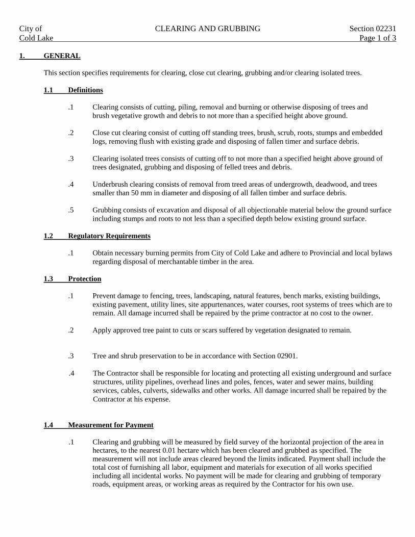
City of CLEARING AND GRUBBING Section 02231
Cold Lake Page 1 of 3
1. GENERAL
This section specifies requirements for clearing, close cut clearing, grubbing and/or clearing isolated trees.
1.1 Definitions
.1 Clearing consists of cutting, piling, removal and burning or otherwise disposing of trees and
brush vegetative growth and debris to not more than a specified height above ground.
.2 Close cut clearing consist of cutting off standing trees, brush, scrub, roots, stumps and embedded
logs, removing flush with existing grade and disposing of fallen timer and surface debris.
.3 Clearing isolated trees consists of cutting off to not more than a specified height above ground of
trees designated, grubbing and disposing of felled trees and debris.
.4 Underbrush clearing consists of removal from treed areas of undergrowth, deadwood, and trees
smaller than 50 mm in diameter and disposing of all fallen timber and surface debris.
.5 Grubbing consists of excavation and disposal of all objectionable material below the ground surface
including stumps and roots to not less than a specified depth below existing ground surface.
1.2 Regulatory Requirements
.1 Obtain necessary burning permits from City of Cold Lake and adhere to Provincial and local bylaws
regarding disposal of merchantable timber in the area.
1.3 Protection
.1 Prevent damage to fencing, trees, landscaping, natural features, bench marks, existing buildings,
existing pavement, utility lines, site appurtenances, water courses, root systems of trees which are to
remain. All damage incurred shall be repaired by the prime contractor at no cost to the owner.
.2 Apply approved tree paint to cuts or scars suffered by vegetation designated to remain.
.3 Tree and shrub preservation to be in accordance with Section 02901.
.4 The Contractor shall be responsible for locating and protecting all existing underground and surface
structures, utility pipelines, overhead lines and poles, fences, water and sewer mains, building
services, cables, culverts, sidewalks and other works. All damage incurred shall be repaired by the
Contractor at his expense.
1.4 Measurement for Payment
.1 Clearing and grubbing will be measured by field survey of the horizontal projection of the area in hectares, to the nearest 0.01 hectare which has been cleared and grubbed as specified. The measurement will not include areas cleared beyond the limits indicated. Payment shall include the total cost of furnishing all labor, equipment and materials for execution of all works specified including all incidental works. No payment will be made for clearing and grubbing of temporary roads, equipment areas, or working areas as required by the Contractor for his own use.
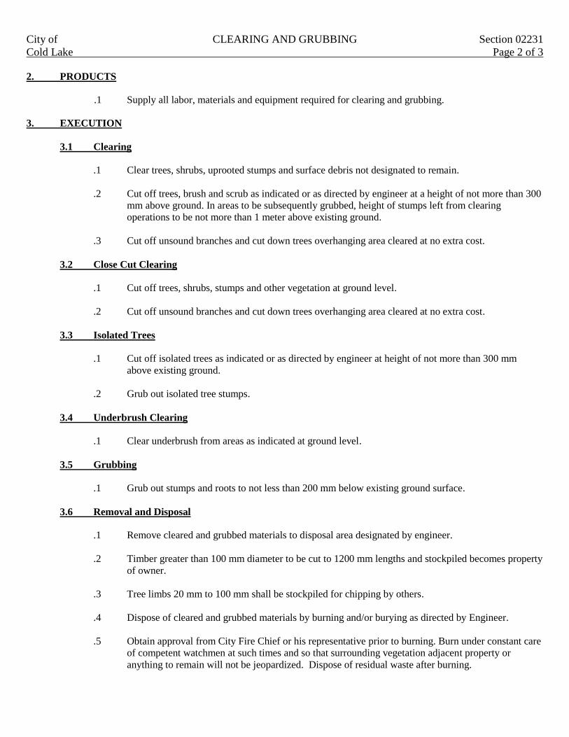
City of CLEARING AND GRUBBING Section 02231
Cold Lake Page 2 of 3
2. PRODUCTS
.1 Supply all labor, materials and equipment required for clearing and grubbing.
3. EXECUTION
3.1 Clearing
.1 Clear trees, shrubs, uprooted stumps and surface debris not designated to remain.
.2 Cut off trees, brush and scrub as indicated or as directed by engineer at a height of not more than 300
mm above ground. In areas to be subsequently grubbed, height of stumps left from clearing
operations to be not more than 1 meter above existing ground.
.3 Cut off unsound branches and cut down trees overhanging area cleared at no extra cost.
3.2 Close Cut Clearing
.1 Cut off trees, shrubs, stumps and other vegetation at ground level.
.2 Cut off unsound branches and cut down trees overhanging area cleared at no extra cost.
3.3 Isolated Trees
.1 Cut off isolated trees as indicated or as directed by engineer at height of not more than 300 mm
above existing ground.
.2 Grub out isolated tree stumps.
3.4 Underbrush Clearing
.1 Clear underbrush from areas as indicated at ground level.
3.5 Grubbing
.1 Grub out stumps and roots to not less than 200 mm below existing ground surface.
3.6 Removal and Disposal
.1 Remove cleared and grubbed materials to disposal area designated by engineer.
.2 Timber greater than 100 mm diameter to be cut to 1200 mm lengths and stockpiled becomes property
of owner.
.3 Tree limbs 20 mm to 100 mm shall be stockpiled for chipping by others.
.4 Dispose of cleared and grubbed materials by burning and/or burying as directed by Engineer.
.5 Obtain approval from City Fire Chief or his representative prior to burning. Burn under constant care
of competent watchmen at such times and so that surrounding vegetation adjacent property or
anything to remain will not be jeopardized. Dispose of residual waste after burning.

City of CLEARING AND GRUBBING Section 02231
Cold Lake Page 3 of 3
.6 Do not commence burning when winds will direct smoke towards existing buildings, street or
highways.
.7 Where the Contractor fails to observe clearing and grubbing restrictions and limitations, and causes
damage to property beyond areas as indicated on the Drawings or as designated, such damages shall
be the Contractor’s liability and shall be corrected immediately at the Contractor’s expense.
3.7 Finished Surface
.1 Leave ground surface in condition suitable for immediate topsoil stripping and grading operations.

City of SITE GRADING Section 02311
Cold Lake Page 1 of 7
1. GENERAL
This section specifies requirements for excavation, drainage excavation, borrow excavation, embankment
construction and disposal of material in accordance with this specification and conforming to lines, grades,
dimensions and typical cross sections shown on plans or established by Engineer.
1.1 Related Work
.1 Site Work Demolition and Removal Section 02225
.2 Clearing and Grubbing Section 02231
.3 Hauling and Haul Roads Section 02321
.4 Tree and Shrub Preservation Section 02901
1.2 Definitions
.1 Topsoil: The top layer of soil containing organic material capable of supporting good vegetative
growth and suitable for use in top dressing, landscaping and seeding.
.2 Topsoil Stripping: Excavation and stockpiling of material capable of supporting good
vegetative growth and suitable for use in top dressing, landscaping and seeding.
.3 Rock Excavation: Rock excavation shall include the removal from their original position of
rock in solid beds or masses, and boulders or detached rock having volume of 1.0 m3 content
or more; and ; placing, disposing or stockpiling of materials as directed by the consultant.
Solid ledge rock, concrete or masonry which requires for its removal drilling, blasting,
wedging, sledging, barring or breaking with a power operated hand tool shall be classified as
rock excavation. Soft or disintegrated rock, concrete or masonry which can be removed with
a hand pick, power operated excavator or shovel; and loose, shaken or previously blasted
rock will not be classified as rock excavation.
.4 Common Excavation: Excavation, placement, and compaction in embankments of all on site
materials whatever nature, which are not included under the definition of topsoil stripping,
waste excavation borrow excavation or rock excavation including dense tills, hardpan,
frozen materials and partially cemented materials which can be ripped and excavated with
heavy construction equipment; also rock, concrete or masonry less than 1.0 m3 in volume
shall be classified as common excavation.
.5 Waste Excavation: Excavation and removal from site or disposed on site as designated by the
Engineer of any material unsuitable for use in work or surplus to requirements.
.6 Borrow Excavation: Excavation, delivery to site, placement and compaction of suitable material
obtained off site or as shown on the drawings and used in embankment.
.7 Transition Material: Refers to the brown dirt layer of material encountered between the bottom of
topsoil and top common material. Transition material to be treated as waste excavation.

City of SITE GRADING Section 02311
Cold Lake Page 2 of 7
.8 Embankment: Material derived from usable excavation and placed above original ground or in
stripped or undercut areas up to sub grade level.
.9 Sub grade Elevation: Elevation immediately below pavement structure.
1.3 Requirements of Regulatory Agencies
.1 Adhere to municipal, provincial and national codes if blasting is required.
1.4 Traffic Provisions
.1 Provide and maintain roadways, walkways and detours for vehicular and pedestrian traffic as
directed by Engineer.
1.5 Measurement for Payment
.1 Common excavations will be measured in cubic meters in its original place. Payment shall cover
compaction of excavated material in fills to 95% Standard Proctor Density and within 2% of
optimum moisture content, any dewatering or conditioning required before or during construction,
leveling, grading, trimming or similar work, watering for compaction, and construction of ditches in
designated locations. Over-excavation will not be paid for. There will be no provision of overhaul
payment. Volumes will be calculated by the Engineer.
.2 Rock excavation volumes will be calculated from cross sections of original rock surface and design
grade line and measured in cubic meters in its original place. Payment shall cover complete
excavation, loading, hauling and disposal.
.3 Disposal of unsuitable material will be the volume measured in cubic meters in its original place.
Payment shall cover complete excavation, loading, hauling, disposal and leveling or stockpiling at
dump locations or other areas as directed.
.4 Disposal of surplus material will be the volume measured in cubic meters in its original place.
Payment shall cover complete excavation, loading, hauling, placing, compacting and leveling or
stockpiling at areas as directed. Topsoil stripping and replacement of disposal sites will be paid under
their respective paid items. There will be no provision of overhaul payment.
.5 Imported clay fill (borrow excavation) will be the volume measured in cubic meters compacted in-
place. The in-place volume shall be determined by cross-sections taken before and after imported fill
placement over the fill area and computer by the average End Area Method. Payment shall cover
borrow pit location, clearing, grubbing, stripping, excavation, loading, hauling, placing, compacting,
leveling and borrow pit restoration.
.6 No additional payment to be made for:
.1 Unnecessary excavations beyond lines established.
.2 Extra handling of windrowed materials blended on embankment slopes.
.3 Moisture adjustment of material.
.4 Construction, maintenance and restoration of haul roads.
.5 Watering for dust control.
.6 Over haul.
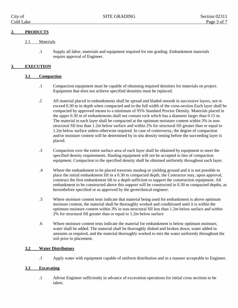
City of SITE GRADING Section 02311
Cold Lake Page 3 of 7
2. PRODUCTS
2.1 Materials
.1 Supply all labor, materials and equipment required for site grading. Embankment materials
require approval of Engineer.
3. EXECUTION
3.1 Compaction
.1 Compaction equipment must be capable of obtaining required densities for materials on project.
Equipment that does not achieve specified densities must be replaced.
.2 All material placed in embankments shall be spread and bladed smooth in successive layers, not to
exceed 0.30 m in depth when compacted and to the full width of the cross-section Each layer shall be
compacted by approved means to a minimum of 95% Standard Proctor Density. Materials placed in
the upper 0.30 m of embankments shall not contain rock which has a diameter larger than 0.15 m.
The material in each layer shall be compacted at the optimum moisture content within 3% in non-
structural fill less than 1.2m below surface and within 2% for structural fill greater than or equal to
1.2m below surface unless otherwise required. In case of controversy, the degree of compaction
and/or moisture content will be determined by in situ density testing before the succeeding layer is
placed.
.3 Compaction over the entire surface area of each layer shall be obtained by equipment to meet the
specified density requirements. Hauling equipment will not be accepted in lieu of compaction
equipment. Compaction to the specified density shall be obtained uniformly throughout each layer.
.4 Where the embankment to be placed traverses muskeg or yielding ground and it is not possible to
place the initial embankment lift in a 0.30 m compacted depth, the Contractor may, upon approval, construct the first embankment lift to a depth sufficient to support the construction equipment. All embankment to be constructed above this support will be constructed in 0.30 m compacted depths, as hereinbefore specified or as approved by the geotechnical engineer.
.5 Where moisture content tests indicate that material being used for embankment is above optimum
moisture content, the material shall be thoroughly worked and conditioned until it is within the optimum moisture content within 3% in non-structural fill less than 1.2m below surface and within 2% for structural fill greater than or equal to 1.2m below surface
.6 Where moisture content tests indicate the material for embankment is below optimum moisture,
water shall be added. The material shall be thoroughly disked and broken down, water added in
amounts as required, and the material thoroughly worked to mix the water uniformly throughout the
soil prior to placement.
3.2 Water Distributors
.1 Apply water with equipment capable of uniform distribution and in a manner acceptable to Engineer.
3.3 Excavating
.1 Advise Engineer sufficiently in advance of excavation operations for initial cross sections to be
taken.

City of SITE GRADING Section 02311
Cold Lake Page 4 of 7
.2 Maintain grades, cross slopes, pumps or ditches to keep excavations free of running or standing
water.
3.4 Topsoil Stripping
.1 Strip topsoil from areas and to depths indicated or directed prior to beginning of excavation and
embankment work. Avoid contamination of topsoil and underlying soil. Strip transition material and
dispose in designated locations.
.2 Topsoil excavated to be stockpiled in a location as directed by Engineer.
3.5 Rock Excavation
.1 If during excavation, material appearing to conform to classification for rock is encountered, notify
Engineer in sufficient time to enable measurements to be made to determine volume of rock.
.2 Remove rock to 300 mm below sub grade elevation indicated.
.3 Provide effective drainage to ditches, leaving no undrained pockets in foundation.
.4 Scale down rock slopes and remove rock fragments which are liable to slide or roll down slopes.
3.6 Solid Rock Excavation
.1 All rock cuts shall be excavated to 0.15 m below the design subgrade surface and then backfilled to
grade with suitable material.
.2 All rock is to be used in the construction of embankments. Where rock is being used in the
embankment, such rock shall be carefully distributed and the cavities filled with approved finer
material or earth to form a dense compact mass. Any large rocks encountered during the construction
of the embankment in the final finishing operations which constitute a hazard to traffic, due to size or
protrusion from the finished embankment surface shall be removed and disposed of as required.
3.7 Waste Excavation
.1 Notify Engineer whenever unsuitable materials are encountered in cut or embankment sections and
remove unsuitable materials to depth and extent directed.
.2 Dispose of waste excavation in waste site designated. If no site is designated dispose of material off
site in an area located by Contractor and approved by Engineer. Costs associated with disposal to be
include in unit rate for waste excavation.
3.8 Borrow Excavation
.1 The borrowing of materials for embankment will be allowed only after all excavations have been
completed and hauled into the embankment.
.2 Obtain from borrow areas indicated on plans additional suitable embankment material.
.1 Engineer to designate location and extent of borrow areas, and allowable depth of cutting.

City of SITE GRADING Section 02311
Cold Lake Page 5 of 7
.2 Shape edges of borrow areas on slopes of 4:1 and provide drainage as directed.
.3 Trim and leave borrow pits in a condition to permit accurate measurement of material
removed.
3.9 Blasting
.1 Control blasting to minimize flying particles.
.2 Treat trees damaged or scarred by flying rock with an approved tree paint or as otherwise directed by
the Engineer.
.3 Cut, remove and place in a designated area trees felled or severely damaged by blast or flying rock
3.10 Side Ditches
.1 Construct side ditches to depths and widths indicated or directed, to permit ready flow of surface
water.
.2 Maintain and keep ditches open and free from debris until final acceptance of work.
3.11 Common Excavation
.1 Scarify or bench existing slopes on side hills or sloping sections to ensure a proper bond between
new materials and exiting surfaces. Obtain prior approval of Engineer for method to be used
.2 Scarify existing ground to a depth of 150 mm and mix embankment material with existing materials
to ensure a good bond.
.3 Do not place material which is frozen or place material on frozen surfaces.
.4 Maintain a slightly sloped surface during construction to ensure ready run off of surface water.
.5 After a period of wet weather remove or scarify, dry and recompact embankment materials softened
by moisture.
.6 Wetting or drying of fill material shall be carried out such that in place fill has a moisture content of
optimum within 3% in non-structural fill less than 1.2m below surface and within 2% for structural
fill greater than or equal to 1.2m below surface
.7 With material containing less than 20% by volume of stone or rock fragments none of which may be
larger than 75 mm:
.1 Place and compact to full width in uniform layers not exceeding 300 mm loose thickness.
Engineer may authorize thicker lifts if specified compaction can be achieved.
.2 Compact each layer to a density of between 95% and 100% of Standard Proctor. 95% for
non-structural fill areas where no subgrade support is required and less than 1.2m fill and
98% for structural fill where actual specifications should be at the discretion of the
geotechnical engineer. Corresponding drawings shown in Section 13 of the Municipal
Engineering Standards, Roadway Design, Figures 5.14 and 5.15.

City of SITE GRADING Section 02311
Cold Lake Page 6 of 7
.8 Where material consists principally of rock:
.1 Place to full width in layers of sufficient depth to contain maximum sized rocks but in no
case is layer thickness to exceed 1m.
.2 Individual rock fragments not exceeding 150 mm in vertical dimension to be permitted
provided their vertical dimension does not exceed one third of fill section depth.
.3 Carefully distribute rock material to fill voids with smaller fragments to form a compact
mass.
.4 Fill surface voids at sub grade level with rock spalls or selected material to from an earth-
tight surface.
.5 Boulders and rock fragments with dimensions exceeding 75 mm not to be placed within 150
mm of pavement sub grade elevation.
.9 Report to engineer any damage to existing trees and/or shrubs. Repairs to be completed in
accordance with Section 02901.
3.12 Embankment
.1 Embankment shall be constructed by depositing, shaping and compacting acceptable excavated
materials. The embankments shall be constructed above the natural ground or other level as required,
in conformity with the lines, grades and cross sections shown on the Drawings.
.2 All suitable material from excavations shall be used in forming embankments or shall be otherwise
disposed of.
.3 Embankment shall be formed of suitable unfrozen material. Stumps, trees, rubbish, sod, topsoil or other unsuitable material shall not be placed in the embankment.
.4 Embankment material shall not be placed on frozen earth, snow or ice, nor shall frozen soils, ice or
snow be placed in any embankment. However, on approval, embankment material may be placed on
the existing ground surface if frost penetration is 0.10 m or less. Any frozen material in the
embankment shall be removed and disposed of at the Contractor’s expense before proceeding with
further embankment construction.
.5 Embankment shall be constructed so that after settlement is complete the required grade and cross-
section is attained at all points. If at anytime before final acceptance of the work the embankment
settles below the required grade, it shall be brought back to the required grade by the Contractor at no
cost to the Owner.
3.13 Dust Control
Control dust during construction operations by watering.

City of SITE GRADING Section 02311
Cold Lake Page 7 of 7
3.14 Finishing and Tolerances
.1 Grading shall include the removal and/or satisfactory placement of all materials necessary
for the construction and preparation of embankment, slopes, drainage works, alignment, to the
grade and cross-section shown on the Drawings or as required.
.2 Conditions requisite for the completion of grading work will be a roadway or other works which
are smooth and compact over the entire width, firm side slopes with regular shoulder lines, clean side
ditches, satisfactory approaches, intersections and entrances, and smooth back slopes. All soft and
yielding material in the roadway, if so directed shall be removed and replaced with acceptable
material, and all loose stones, clods, weeds, trash, etc. shall be removed from the roadway, side
slopes, ditches and back slopes. All improperly compacted material shall be excavated, brought to
optimum moisture content if required, and re-compacted at the Contractor’s own expense. On the
side slopes and back slopes, and in the bottom of ditches, all projecting boulders must be removed or
broken off at least flush with the lines and grades, and the resultant cavities, if any, backfilled.
.3 Blade finish surfaces in cut and fill areas free from ruts, depressions, rocks in excess of 75 mm and
debris.
.4 Roll finished surfaces to a tight dense condition.
.5 Surfaces to be within 75 mm of design elevations but not uniformly high or low.
3.15 Surplus Material
.1 Surplus material in excavation which is not required in the adjacent embankments, test fills, entrances or subsidiary road connections, shall be otherwise utilized or disposed of in the area indicated on the Drawings or as required. No material shall be wasted, unless approved. In no case shall material be deposited above the established grade without written approval by the Engineer.
3.16 Maintenance
.1 Maintain finished surface in a conditions in accordance with this section until acceptance by
Engineer.

City of TRENCH EXCAVATION, BACKFILL Section 02315
Cold Lake AND COMPACTION Page 1 of 11
1. GENERAL
This section specifies requirements for excavating trenches and backfilling for installation of pipelines, sewers,
conduits and appurtenances.
1.1 Related Work
.1 Hauling and haul roads Section 02321
.2 Soil insulation Section 02344
.3 Boring or jacking conduits Section 02445
.4 Water mains Section 02511
.5 Sub drain systems Section 02620
.6 Storm sewer mains Section 02560
.7 Corrugated steel pipe culverts Section 02610
.8 Catch basin leads Section 02562
.9 Manholes and catch basins Section 02563
.10 Sanitary sewer mains Section 02530
.11 Sanitary and storm sewer force mains Section 02531
.12 Water, sanitary sewer, storm sewer service connection Section 02564
.13 Tree and shrub preservation Section 02901
1.2 Definitions
.1 Common excavation: Excavation, placement and compaction in embankments of all on site materials
whatever nature, which are not included under the definition of topsoil stripping, waste excavation,
borrow excavation or rock excavation; including dense tills, hardpan, frozen materials and partially
cemented materials and rock, concrete or masonry less than 1.0m³ in volume.
.2 Rock excavation: Rock excavation shall be paid for when the material encountered consists of mass
or bedrock or a boulder of volume greater than 1 cubic meter and requires for its removal drilling,
blasting wedging, sledging, barring or breaking away from it’s parent mass. It shall be the
Contractors responsibility to demonstrate, to the Engineers satisfaction that the material cannot be
removed or that difficulty is being experienced through excavation by conventional means. In doing
so, the Contractor may be required by the Engineer to seek and explore planes of weakness or layers
that may ease the excavation process. Frozen material is not classified as rock.
.3 Bedding Material: Materials placed at the bottom of the trench beneath and up to the spring line of
the pipe.
.4 Pipe foundations: Sub grade material immediately below bedding.
.5 Bedding Backfill: Non frozen material placed within the trench, above the spring line of the pipe to
300 mm above the crown of the pipe in layers not exceeding 300mm and compacted by manual
forces (wacker tampers) to min 95 % Standard Proctor Density.
.6 Class 1 Backfill: Class I backfilling shall consist of backfilling the trench with non frozen sand or
gravel compacted in even layers not exceeding 300 mm in depth so that there is no subsequent
subsidence in the trench. Backfill shall be compacted to a minimum of 100% Standard Proctor
Density (SPD) for the upper 300mm, 98% SPD below the 300mm within existing and new roads,
98% SPD for the upper 1.5m outside the road structure and 95% SPD for the remainder of the trench
outside the road structure, as shown in Section 13 of the Municipal Engineering Standards, Roadway
Design, Figure 5.16. Filicrete may be used in lieu of Class 1 backfill.
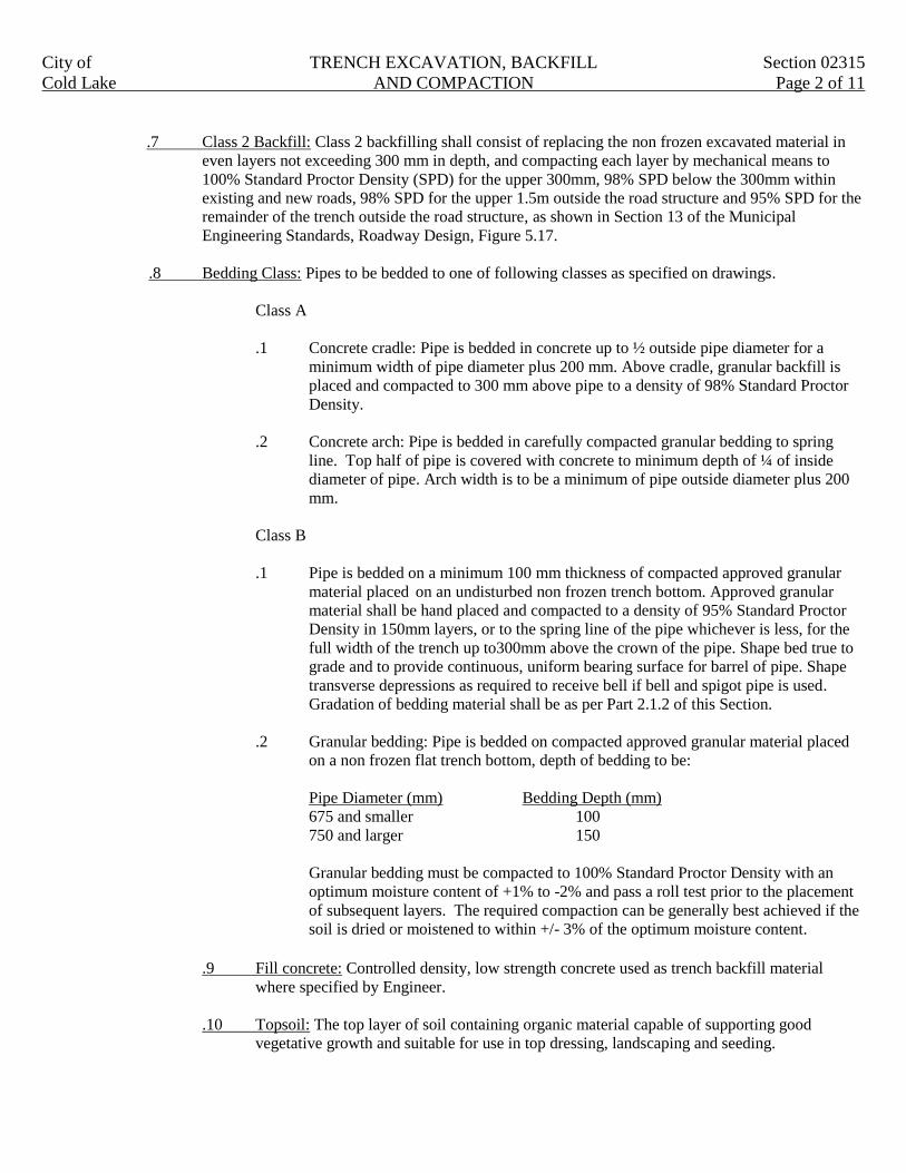
City of TRENCH EXCAVATION, BACKFILL Section 02315
Cold Lake AND COMPACTION Page 2 of 11
.7 Class 2 Backfill: Class 2 backfilling shall consist of replacing the non frozen excavated material in
even layers not exceeding 300 mm in depth, and compacting each layer by mechanical means to
100% Standard Proctor Density (SPD) for the upper 300mm, 98% SPD below the 300mm within
existing and new roads, 98% SPD for the upper 1.5m outside the road structure and 95% SPD for the
remainder of the trench outside the road structure, as shown in Section 13 of the Municipal
Engineering Standards, Roadway Design, Figure 5.17.
.8 Bedding Class: Pipes to be bedded to one of following classes as specified on drawings.
Class A
.1 Concrete cradle: Pipe is bedded in concrete up to ½ outside pipe diameter for a
minimum width of pipe diameter plus 200 mm. Above cradle, granular backfill is
placed and compacted to 300 mm above pipe to a density of 98% Standard Proctor
Density.
.2 Concrete arch: Pipe is bedded in carefully compacted granular bedding to spring
line. Top half of pipe is covered with concrete to minimum depth of ¼ of inside
diameter of pipe. Arch width is to be a minimum of pipe outside diameter plus 200
mm.
Class B
.1 Pipe is bedded on a minimum 100 mm thickness of compacted approved granular
material placed on an undisturbed non frozen trench bottom. Approved granular
material shall be hand placed and compacted to a density of 95% Standard Proctor
Density in 150mm layers, or to the spring line of the pipe whichever is less, for the
full width of the trench up to300mm above the crown of the pipe. Shape bed true to
grade and to provide continuous, uniform bearing surface for barrel of pipe. Shape
transverse depressions as required to receive bell if bell and spigot pipe is used.
Gradation of bedding material shall be as per Part 2.1.2 of this Section.
.2 Granular bedding: Pipe is bedded on compacted approved granular material placed
on a non frozen flat trench bottom, depth of bedding to be:
Pipe Diameter (mm) Bedding Depth (mm)
675 and smaller 100
750 and larger 150
Granular bedding must be compacted to 100% Standard Proctor Density with an
optimum moisture content of +1% to -2% and pass a roll test prior to the placement
of subsequent layers. The required compaction can be generally best achieved if the
soil is dried or moistened to within +/- 3% of the optimum moisture content.
.9 Fill concrete: Controlled density, low strength concrete used as trench backfill material
where specified by Engineer.
.10 Topsoil: The top layer of soil containing organic material capable of supporting good
vegetative growth and suitable for use in top dressing, landscaping and seeding.

City of TRENCH EXCAVATION, BACKFILL Section 02315
Cold Lake AND COMPACTION Page 3 of 11
1.3 Protection
.1 Existing buried Utilities
.1 Size, depth and location of existing utilities shown on Drawings are for guidance only;
completeness and accuracy are not guaranteed.
.2 Prior to commencing any excavation work, notify applicable utility authorities, and establish
location and state of use of buried services. Clearly mark such locations to prevent
disturbance during work.
.3 Maintain and protect from damage, water, sewer, gas, electric or other utilities encountered.
.4 Obtain written authorization of Owner of utility and Engineer before moving or otherwise
disturbing utility.
.2 Existing Surface Features
.1 Protect existing buildings, trees and other plants, lawns, fencing, service poles, wires or
paving located within right of way or adjoining properties from damage while work is in
progress. Repair to Engineer’s satisfaction any damage which may occur.
.2 Where excavation necessitates root or branch cutting do so only under direct control of the
Engineer.
.3 Protect existing trees and shrubs in accordance with section 02901.
.3 Shoring and Bracing
.1. Whenever shoring, sheeting, timbering and bracing of excavations is required, engage
services of a professional engineer to design and assume responsibility for adequacy of
shoring and bracing. Professional engineer is to be registered in Alberta.
.2 When requested by the Engineer, submit for review drawings and calculations signed and
stamped by the professional engineer responsible for their preparation.
.3 Close sheeting, when required, to be designed and constructed to prevent adjacent soil or
water from entering excavation.
.4 Access
Maintain unobstructed access to fire and police appurtenances, telephone, electric, water, sewer, gas
or other public utilities and private properties.
.5 Flooding
Protect open excavation against flooding and damage from surface water runoff or groundwater
seepage.

City of TRENCH EXCAVATION, BACKFILL Section 02315
Cold Lake AND COMPACTION Page 4 of 11
1.4 Safety Requirements
.1 Observe and adhere to all applicable section s of the Alberta Regulations 271/76 or any revisions
thereto made under the Occupational Health and Safety Act covering the worker safety in trenches
and excavations, shoring and bracing as required. Open cut trenches shall be shaped as required by
the Act and the Accident Prevention Regulations of the Occupational Health and Safety Division of
the Department of Labor and Municipal Ordinances and as may be necessary to protect life, property,
the environment and the Work.
.2 Adhere to all crossing permit (railway, pipeline, telecommunications, etc) requirements.
.3 Provide barricades, flares, etc. to adequately denote area of excavation adjacent to roadways and
public thoroughfares.
1.5 Measurement for Payment
.1 Trenching and backfilling will not be measured as units for payment except for building service
connections. Payment shall be included in the price bid per meter for the pipe being installed.
.2 Rock excavation will be measured in cubic meters in its original place. Boulders exceeding 1.0 m3 in
volume shall be measured complete, as removed from the trench. Ledge rock shall be measured by
actual length and actual width of the trench. A greater width than the approved width will not be paid
for. Depth shall be measured by the distance from the surface of the rock to the level to which the
Engineer orders the rock to be excavated. Any over excavation will not be paid for. Payment for rock
excavation shall include hauling and disposing of the material excavated at a location approved, and
replacement with suitable material.
.3 Imported granular material used for stabilizing trench bases and replacement of unsuitable material
will be measured in cubic meters. The volume of the material used shall be computed from the length
and depth specified, and the width which shall be the trench width as specified. Payment shall be
compensation in full for supplying and hauling the material to the site, placing and compacting, the
cost of any extra excavation involved and the disposal of any extra excavated material.
.4 Filter fabric used for wrapping trench stabilizing gravel will be measured in square meters installed.
Payment shall be compensation in full for supply and hauling the material to the site, placing, sewing,
welding, cutting and all other incidentals necessary to complete the work prescribed.
.5 The cost of supplying, placing, maintaining and removal of shoring, bracing, cofferdams,
underpinning and dewatering equipment will be incidental to the price paid for pipe installation. No
extra payment will be made.
2. PRODUCTS
2.1 Bedding and Initial Backfill Materials
.1 Well graded sand consisting of hard durable particles free from clay lumps, cementation, organic
material, frozen material and other deleterious materials.

City of TRENCH EXCAVATION, BACKFILL Section 02315
Cold Lake AND COMPACTION Page 5 of 11
2. The material shall meet the following gradation:
Seive Size
(10-6m)
Percent Passing
( by weight)
12,500 100
5,000 90 - 100
1,250 65 – 95
630 50 – 95
315 35 - 80
160 18 - 45
80 2 - 10
.3 Native hand placed material may be used as initial backfill gradation.
.4 Material to be used as specified by Engineer or as shown on drawing.
.5 Concrete required for Class A bedding, grades, supports, encasement to be 25 MPa sulphate resistant
(Type 50) to Section 03300.
.6 Native backfill to be approved material selected from trench excavation or other source, unfrozen
and free from deleterious material and with moisture content within 2% of optimum.
2.2 Roadway Trench Backfill Material
.1 To minimize fill settlement under self weight, excavated soil with a moisture content exceeding 2%
of optimum shall be conditioned and dried prior to use as backfill.
.2 Wet fill material must be dried or blended with drier material to produce a uniform homogenous
material prior to use as a trench backfill. If this is not practical, the wet material should be wasted or
used in landscape areas and berms where bearing capacity is not required.
.3 Suitable replacement soils would include imported clay with a moisture content within 2 % of its
optimum moisture content for compaction or imported granular materials suitable for compaction.
Class I Backfill Material
.1 Material for Class 1 backfill shall consist of sound, hard, durable, uniformly graded crushed gravel and shall
not contain organic or soft materials, materials that break up when alternately frozen and thawed or wetted
and dried, or other deleterious materials. When compacted to +1% to -2% of the optimum moisture content to
not less than 95% of the maximum dry density corrected for the stone content as determined by ASTM D698,
the material shall have a minimum bearing ratio as defined ASTM D1 883, of fifteen percent (15%).
.2 Class 1 backfill shall meet the following gradation when tested to ASTM C1 36:
Sieve Size
(10-6 m)
Percent Passing
(by weight)
60,000 100
16,000 32-85
5,000 20-65
315 6-30
80 2-10
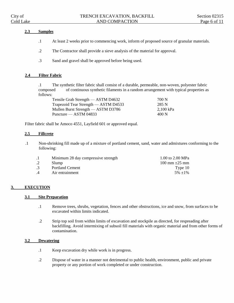
City of TRENCH EXCAVATION, BACKFILL Section 02315
Cold Lake AND COMPACTION Page 6 of 11
2.3 Samples
.1 At least 2 weeks prior to commencing work, inform of proposed source of granular materials.
.2 The Contractor shall provide a sieve analysis of the material for approval.
.3 Sand and gravel shall be approved before being used.
2.4 Filter Fabric
.1 The synthetic filter fabric shall consist of a durable, permeable, non-woven, polyester fabric
composed of continuous synthetic filaments in a random arrangement with typical properties as
follows:
Tensile Grab Strength — ASTM D4632 700 N
Trapezoid Tear Strength — ASTM D4533 285 N
Mullen Burst Strength — ASTM D3786 2,100 kPa
Puncture — ASTM 04833 400 N
Filter fabric shall be Amoco 4551, Layfield 601 or approved equal.
2.5 Fillcrete
.1 Non-shrinking fill made up of a mixture of portland cement, sand, water and admixtures conforming to the
following:
.1 Minimum 28 day compressive strength 1.00 to 2.00 MPa
.2 Slump 100 mm ±25 mm
.3 Portland Cement Type 10
.4 Air entrainment 5% ±1%
3. EXECUTION
3.1 Site Preparation
.1 Remove trees, shrubs, vegetation, fences and other obstructions, ice and snow, from surfaces to be
excavated within limits indicated.
.2 Strip top soil from within limits of excavation and stockpile as directed, for respreading after
backfilling. Avoid intermixing of subsoil fill materials with organic material and from other forms of
contamination.
3.2 Dewatering
.1 Keep excavation dry while work is in progress.
.2 Dispose of water in a manner not detrimental to public health, environment, public and private
property or any portion of work completed or under construction.
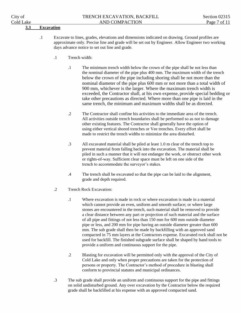
City of TRENCH EXCAVATION, BACKFILL Section 02315
Cold Lake AND COMPACTION Page 7 of 11 3.3 Excavation
.1 Excavate to lines, grades, elevations and dimensions indicated on drawing. Ground profiles are
approximate only. Precise line and grade will be set out by Engineer. Allow Engineer two working
days advance notice to set out line and grade.
.1 Trench width:
.1 The minimum trench width below the crown of the pipe shall be not less than the nominal diameter of the pipe plus 400 mm. The maximum width of the trench
below the crown of the pipe including shoring shall be not more than the
nominal diameter of the pipe plus 600 mm or not more than a total width of 900 mm, whichever is the larger. Where the maximum trench width is
exceeded, the Contractor shall, at his own expense, provide special bedding or take other precautions as directed. Where more than one pipe is laid in the same trench, the minimum and maximum widths shall be as directed.
.2 The Contractor shall confine his activities to the immediate area of the trench.
All activities outside trench boundaries shall be performed so as not to damage
other existing features. The Contractor shall generally have the option of
using either vertical shored trenches or Vee trenches. Every effort shall be
made to restrict the trench widths to minimize the area disturbed.
.3 All excavated material shall be piled at least 1.0 m clear of the trench top to
prevent material from falling back into the excavation. The material shall be
piled in such a manner that it will not endanger the work, or obstruct other work
or rights-of-way. Sufficient clear space must be left on one side of the
trench to accommodate the surveyor’s stakes.
.4 The trench shall be excavated so that the pipe can be laid to the alignment,
grade and depth required.
.2 Trench Rock Excavation:
.1 Where excavation is made in rock or where excavation is made in a material
which cannot provide an even, uniform and smooth surface; or where large
stones are encountered in the trench, such material shall be removed to provide
a clear distance between any part or projection of such material and the surface
of all pipe and fittings of not less than 150 mm for 600 mm outside diameter
pipe or less, and 200 mm for pipe having an outside diameter greater than 600
mm. The sub grade shall then be made by backfilling with an approved sand
compacted in 75 mm layers at the Contractors expense. Excavated rock shall not be
used for backfill. The finished subgrade surface shall be shaped by hand tools to
provide a uniform and continuous support for the pipe.
.2 Blasting for excavation will be permitted only with the approval of the City of
Cold Lake and only when proper precautions are taken for the protection of
persons or property. The Contractor’s method of procedure in blasting shall
conform to provincial statutes and municipal ordinances.
.3 The sub grade shall provide an uniform and continuous support for the pipe and fittings
on solid undisturbed ground. Any over excavation by the Contractor below the required
grade shall be backfilled at his expense with an approved compacted sand.
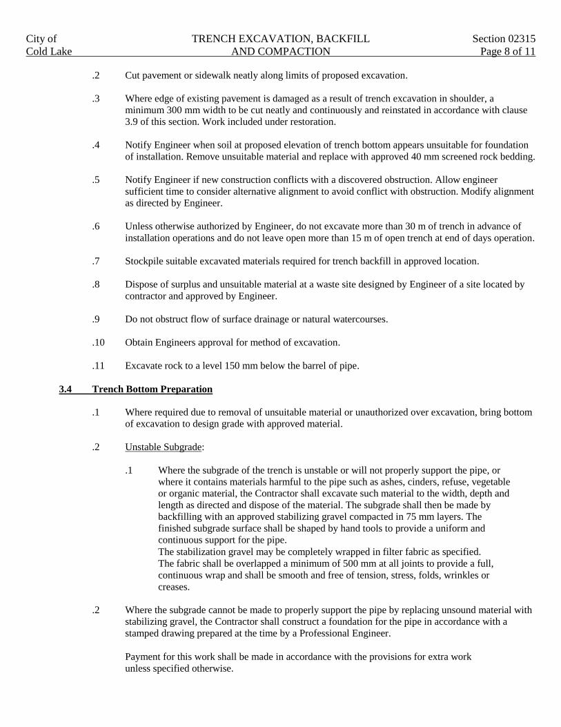
City of TRENCH EXCAVATION, BACKFILL Section 02315
Cold Lake AND COMPACTION Page 8 of 11
.2 Cut pavement or sidewalk neatly along limits of proposed excavation.
.3 Where edge of existing pavement is damaged as a result of trench excavation in shoulder, a
minimum 300 mm width to be cut neatly and continuously and reinstated in accordance with clause
3.9 of this section. Work included under restoration.
.4 Notify Engineer when soil at proposed elevation of trench bottom appears unsuitable for foundation
of installation. Remove unsuitable material and replace with approved 40 mm screened rock bedding.
.5 Notify Engineer if new construction conflicts with a discovered obstruction. Allow engineer
sufficient time to consider alternative alignment to avoid conflict with obstruction. Modify alignment
as directed by Engineer.
.6 Unless otherwise authorized by Engineer, do not excavate more than 30 m of trench in advance of
installation operations and do not leave open more than 15 m of open trench at end of days operation.
.7 Stockpile suitable excavated materials required for trench backfill in approved location.
.8 Dispose of surplus and unsuitable material at a waste site designed by Engineer of a site located by
contractor and approved by Engineer.
.9 Do not obstruct flow of surface drainage or natural watercourses.
.10 Obtain Engineers approval for method of excavation.
.11 Excavate rock to a level 150 mm below the barrel of pipe.
3.4 Trench Bottom Preparation
.1 Where required due to removal of unsuitable material or unauthorized over excavation, bring bottom
of excavation to design grade with approved material.
.2 Unstable Subgrade:
.1 Where the subgrade of the trench is unstable or will not properly support the pipe, or
where it contains materials harmful to the pipe such as ashes, cinders, refuse, vegetable
or organic material, the Contractor shall excavate such material to the width, depth and
length as directed and dispose of the material. The subgrade shall then be made by
backfilling with an approved stabilizing gravel compacted in 75 mm layers. The
finished subgrade surface shall be shaped by hand tools to provide a uniform and
continuous support for the pipe.
The stabilization gravel may be completely wrapped in filter fabric as specified.
The fabric shall be overlapped a minimum of 500 mm at all joints to provide a full,
continuous wrap and shall be smooth and free of tension, stress, folds, wrinkles or
creases.
.2 Where the subgrade cannot be made to properly support the pipe by replacing unsound material with
stabilizing gravel, the Contractor shall construct a foundation for the pipe in accordance with a
stamped drawing prepared at the time by a Professional Engineer.
Payment for this work shall be made in accordance with the provisions for extra work
unless specified otherwise.

City of TRENCH EXCAVATION, BACKFILL Section 02315
Cold Lake AND COMPACTION Page 9 of 11
3.5 Pipe Bedding and Initial Backfill
.1 Concrete Bedding and Encasement
.1 Do concrete work to Section 03300. Place concrete details indicated or directed.
.2 Pipe may be positioned on concrete blocks or cradles to facilitate placing of concrete
bedding. When necessary rigidly anchor or weight pipe to prevent flotation when concrete is
placed.
.3 Do not backfill over concrete until 60% of compressive concrete strength has been attained
or within 7 days after placing.
.2 Granular Bedding
.1 Place granular bedding materials to Class B unless otherwise indicated on drawings.
.2 Shape bed true to grade to provide continuous uniform bearing surface for pipe exterior. Do
not use blocks when bedding pipe.
.3 Shape transverse depressions in bedding as required to accommodate bells when applicable.
.4 Compact full width of bed to a density of 95% Standard Proctor.
.5 Place layers simultaneously on both sides of installed work to equalize loading.
.6 Place material by hand under, around, and over pipe until 300 mm of cover is provided.
Dumping material directly on pipe will not be permitted.
3.6 Backfilling
.1 Bedding and initial backfilling shall be as specified for the particular pipe installed.
.2 General backfilling:
.1 Class 1 backfill as defined in Section 1.2 - Definitions shall be used underneath all
existing asphalt road or concrete areas. Class 2 backfill as defined in Section 1.2. Definitions
shall be used in all other areas including future roads, boulevards and open areas.
.2 No boulders, rock, ice, snow, organic material or debris shall be permitted in the trench.
These unsuitable materials shall be hauled away.
.3 All surplus excavated material shall also be hauled away, or disposed of as directed. In the
event of deficiency of backfill material, suitable material shall be supplied by the Contractor
at his expense.
.4 All trenches shall be backfilled as the work proceeds and no more than 30 m shall be left
open at the end of a days work.
3.7 Backfill Compaction
.1 The Contractor shall be responsible for adequate compaction of the trenches and for the correction of settlement during the maintenance period of the Contract. Mechanical compaction equipment shall not be used until there is sufficient cover to prevent damage to the
pipe.
City of TRENCH EXCAVATION, BACKFILL Section 02315
Cold Lake AND COMPACTION Page 10 of 11
.2 The type of compaction equipment shall be chosen with regard to minimizing the vibration effect
on nearby buildings and utilities. The Contractor shall inspect the condition of buildings prior to
construction. The Contractor is responsible for any damage caused to buildings due to construction.
3.8 Testing Backfill Compaction
.1 Compaction results shall be based on a minimum of one density test per 100 meters of trench for
each 1.0 meter of compacted vertical backfill. Additional tests may be called for by the City of Cold
Lake as deemed necessary.
.2 If a density test indicates insufficient compaction at any depth, then two more densities, that are
proportionally representative of trench length, shall be taken at that depth. If the average of these
tests is below the required density, the trench shall be re-excavated and re-compacted to meet the
specified density.
.3 This testing in no way relieves the Contractor of his maintenance responsibilities with respect to
settlements as specified. The Contractor shall repair any settlement and damaged surface
improvements due to the settlement which occurs during the maintenance period.
.4 The cost of all initial testing will be borne by the Contractor. Non-conformity with the specified
density or moisture content shall constitute sufficient grounds for rejection of the work.
3.9 Trench Backfill and Compaction for Shallow Utilities
.1 This clause shall apply to the installation of power, gas, telephone and cable in new development
areas.
.2 Road and lane crossings, roads, lanes or other areas that will be subject to traffic, are to be backfilled
as outlined under Class 1 or Class 2 backfill in clause 1.2 of this section.
.3 Trenches in landscaped areas; such as boulevards, rear yard easements, front yard easements, side
yard easement, park etc; shall be backfilled and compacted as follows:
.1 Place initial 350 mm ±lift of native backfill material and compact to 95% standard proctor
density.
.2 Place balance of backfill material in 300mm lifts and compact to 95% Standard Proctor
Density.
.3 Following compaction of final lift, fill depression with native material leaving a slight hump
over trench to accommodate future settlement. Level surrounding area.
3.10 Fill Concrete Backfill
.1 Place bedding and initial backfill material as per clause 3.6.
.2 Backfill with fill concrete described in Section 2.5 to level directed by Engineer.
.3 Vibrate to ensure all voids are filled.
.4 Allow 48 hours curing time prior to working over top of fill concrete.
City of TRENCH EXCAVATION, BACKFILL Section 02315
Cold Lake AND COMPACTION Page 11 of 11
3.11 Restoration
.1 Replace topsoil as directed by Engineer.
.2 Restore traveled areas to the pavement or concrete structure shown on the contract drawing.
.3 Clean and reinstate areas affected by work as directed.

City of ROADWAY EXCAVATION, BACKFILL Section 02317
Cold Lake AND SUBGRADE PREPARATION Page 1 of 7
1. GENERAL
This section specifies requirements for road excavation, road drainage excavation, borrow excavation, embankment
construction and disposal of material in accordance with specification and conforming to lines, grades, dimensions,
and typical cross sections shown of plans or established by Engineer.
1.1 Related Work
.1 Site work Demolition and Removal Section 02225
.2 Clearing and Grubbing Section 02231
.3 Hauling and Haul Roads Section 02321
.4 Site Grading Section 02311
.5 Roadway Geotextile Section 02342
.6 Sub Drain Systems Section 02620
1.2 Definitions
.1 Topsoil Stripping: excavation and stockpiling of material capable of supporting good vegetative
growth and suitable for use in top dressing, landscaping and seeding.
.2 Common Excavation: excavation, placement and compaction in embankments of all on site material
whatever nature, which are not included under the definition of topsoil stripping, waste excavation,
borrow excavation or rock excavation, including dense tills, hardpan, frozen materials and partially
cemented materials which can be ripped and excavated with heavy construction equipment.
.3 Waste Excavation: excavation and removal from site or disposed on site as designated by engineer
of any material unsuitable for use in work or surplus to requirements.
.4 Rock Excavation: rock excavation shall be paid for when the material encountered consists of mass
or bedrock or a boulder of volume greater than 1.0 m³. Such rock excavation is divided into two
categories; Type ‘A’ and Type ‘B’, contingent upon its hardness and difficulty experienced in
excavation. It shall be the Contractors responsibility to demonstrate to the Engineers satisfaction that
the material cannot be removed or that difficulty is being experienced through excavation by
conventional means. In doing so, the contractor may be required by the Engineer to seek and explore
planes of weakness or layers that may ease the excavation process. Frozen material is not classified
as rock.
.1 Type ‘A’ Rock
Type ‘A’ rock refers to materials such as fractured sandstone, shale or ledge rock which can
be removed by a backhoe for the depth of excavation. For open excavation, it refers to
materials which in the opinion of the Engineer result in:
a) Substantial delay or decrease in the normal rate of excavation using conventional
equipment.
b) Significant damage or wear to the excavating equipment.
.2 Type ‘B’ Rock
Type ‘B’ rock required drilling, blasting, wedging or jack hammering to remove as
determined by the Engineer.

City of ROADWAY EXCAVATION, BACKFILL Section 02317
Cold Lake AND SUBGRADE PREPARATION Page 2 of 7
.5 Borrow Excavation: Excavation, delivery to site, placement and compaction of suitable material
obtained off site and used in embankment.
.6 Unsuitable Sub grade: Material at design sub grade level not suitable for pavement structure sub
grade, shall be removed as directed by Engineer and replaced with suitable material.
.7 Embankment: Material placed above original ground or in stripped or undercut areas up to sub grade
elevation.
.8 Pavement Structure: Combination of layers of unbound or stabilized granular sub base, base and
asphalt or concrete surfacing.
.9 Sub grade Elevation: Elevation immediately below pavement structure.
.10 Sub grade Preparation: Shaping, scarifying, conditioning, blading and compacting of sub grade.
1.3 Requirements of Regulatory Agencies
.1 Adhere to municipal, provincial, and national codes if blasting is required.
1.4 Traffic Provisions
.1 Provide and maintain roadways, walkways and detours for vehicular and pedestrian traffic as
directed by Engineer.
1.5 Protection
.1 Existing Surface Features
.1 Protect existing buildings, trees and other plants, lawns, fencing, service poles, wires or
paving located within right of way or adjoining properties from damage while work is in
progress. Repair to Engineer’s satisfaction any damage, which may occur.
.2 Trees and Shrubs
.1 Where excavation necessitates root or branch cutting, do so only under direct control of the
Engineer.
.2 Protect existing trees and shrubs in accordance with Section 02901.
1.6 Safety Requirements
.1 Adhere to municipal and provincial requirements relating to safety of trenching work, including
shoring and bracing as required.
.2 Adhere to all crossing permit (railway, pipeline, telecommunications duct, etc.) requirements.
.3 Provide barricades, flares, etc. to adequately denote area of excavation adjacent to roadways.
City of ROADWAY EXCAVATION, BACKFILL Section 02317
Cold Lake AND SUBGRADE PREPARATION Page 3 of 7
1.7 Measurement for Payment
.1 Excavated materials to be measured and paid for in cubic meters for insitu cut. Volumes will be
calculated by the Engineer.
.2 Unit price bid shall be full compensation for all work necessary for excavating the specified material
and execution as described in clause 3 execution of this section.
.3 Volume excavated from solid rock masses to be calculated from cross sections of original rock
surface and design grade line for excavation. Measurements for boulders and rock fragments
exceeding 0.75 cubic meters in volume to be determined form three mutually perpendicular
dimensions.
.4 Sub grade preparation to be measured in square meters for the area of sub grade prepared beneath
pavement, curbs and sidewalks.
.5 Removal of unsuitable sub grade material and replacement with pit run gravel backfill materials to be
measured in cubic meters for the volume of material removed and the volume of pit run gravel
material supplied and placed as described in Clause 3, Execution of this Section.
.6 No measurement to be made for:
.1 Unnecessary excavation beyond lines established.
.2 Extra handling of windrowed materials blended on embankment slopes.
.3 Moisture adjustment of material.
.4 Construction, maintenance, and restoration of haul routes.
.5 Sub grade preparation where unsuitable sub grade is removed and replaced with granular
material.
.6 Sub grade preparation in areas having fills grater than 300 mm.
.7 Overhaul.
2. PRODUCTS
2.1 Materials
.1 Embankment Material
.1 Embankment materials to be approved by the Engineer.
.2 Sub grade replacement material.
.1 Unsuitable sub grade replacement aggregates shall consist of the following:
.1 Native fill sand.
.2 75 mm or 150 mm pit run gravel.
.3 Other material approved by the Engineer.
Material to be used as specified by the Engineer, or as shown on the drawing.

City of ROADWAY EXCAVATION, BACKFILL Section 02317
Cold Lake AND SUBGRADE PREPARATION Page 4 of 7
3. EXECUTION
3.1 Compaction
.1 Compaction equipment must be capable of obtaining required densities for materials on project.
Equipment that does not achieve specified densities must be replaced.
.2 Field tests for density and moisture content shall be taken by a third party competent in materials
testing. The cost of this testing shall be borne by the Contractor. Nonconformity with the specified
density or moisture content shall constitute sufficient grounds for rejection of the work.
.3 Trench backfill encountered in the preparation of the subgrade which has not been compacted
sufficiently, shall be excavated and re-compacted.
.4 The Contractor shall be responsible for any repair required to road works arising from subsidence of
trenches after the completion of the maintenance period of the underground services
3.2 Testing Compaction
.1 Compaction results shall be based on a minimum of one density test per 1,500 m² of road. Additional tests
may be called for by the City of Cold Lake as deemed necessary.
.2 Field density tests shall conform to ASTM D1 556, ASTM D21 67, or ASTM D2922 for comparison with a
maximum density determined according to ASTM D698 Method “A”.
3.3 Water Distributors
.1 Apply water with equipment capable of uniform distribution and in a manner acceptable to Engineer.
3.4 Excavating
.1 Advise Engineer sufficiently in advance of excavation operations for initial cross section to be taken.
.2 Maintain crowns, cross slopes, pumps or ditches to keep excavations free of running or standing
water.
3.5 Topsoil Stripping
.1 Strip topsoil from areas and to depths indicated or directed prior to beginning of excavation and
embankment work. Avoid contamination of topsoil and underlying soil.
.2 Topsoil excavated to be stockpiled in a location as directed by Engineer.
3.6 Rock excavation
.1 If during excavation, material appearing to conform to classification for rock is encountered, notify
Engineer in sufficient time to enable measurements to be made to determine volume of rock.
.2 Remove rock to 300 mm below sub grade elevation indicated.
.3 Provide effective drainage to ditches, leaving no undrained pockets in foundation.
.4 Scale down rock slopes and remove rock fragments, which are liable to slide or roll down slopes.

City of ROADWAY EXCAVATION, BACKFILL Section 02317
Cold Lake AND SUBGRADE PREPARATION Page 5 of 7
3.7 Common Excavation
.1 Material designated as common excavation to be excavated, hauled and compacted in designated fill
areas on site.
3.8 Waste Excavation
.1 Notify Engineer whenever unsuitable materials are encountered in cut or embankment sections and
remove unsuitable materials to depth and extent directed.
.2 Dispose of waste excavation at designated waste site. If no waste site is designated dispose of
material off site in an area located by contractor and approved by Engineer. Costs associated with
disposal to be included in unit rate for waste excavation.
3.9 Borrow Excavation
.1 Use all suitable materials removed from excavation in embankments before taking material from
borrow area.
.2 Obtain from borrow areas located on project property additional suitable embankment material.
.1 Engineer to designate location and extend of borrow areas, and allowable depth of cutting.
.2 Shape edges of borrow areas on slopes of 4:1 and provide drainage as directed.
.3 Trim and leave borrow pits in a condition to permit accurate measurements of material
removed.
3.10 Unsuitable Sub grade
.1 Notify Engineer when unsuitable materials are encountered at design sub grade elevation. Sub cut
and dispose of unsuitable material and replace with a compacted approved material. Material shall be
placed in successive layers not exceeding 150 mm in depth and compacted to a minimum of 98%
Standard Proctor Density.
.2 When sub grade after sub cutting is still unsuitable, geotextile may be installed at direction of
Engineer.
3.11 Subgrade Preparation
.1 The subgrade of 150 mm depth shall be scarified and compacted to a minimum of 100% Standard
Proctor Density with an optimum moisture content of +1% to -2% over the full width of the cross-
section and pass a roll test prior to the placement of subsequent layers. The required compaction can
be generally best achieved if the soil is dried or moistened to within +/- 3% of the optimum moisture
content. The material shall be worked to ensure as much uniformity as possible in material.
.2 Water shall be added or the material shall be aerated to bring the moisture content within
specification. The supply of water shall be the responsibility of the Contractor.
.3 Prepared areas should be compacted to a level slightly above the final sub grade elevation then cut
back to final grade.
City of ROADWAY EXCAVATION, BACKFILL Section 02317
Cold Lake AND SUBGRADE PREPARATION Page 6 of 7
3.12 Blasting
.1 Control blasting to minimize flying particles.
.2 Treat trees damaged or scarred by flying rock are to be treated in accordance with Section 02901.
.3 Cut, remove and place in a designated area trees felled or severely damaged by blast of flying rock.
3.13 Side Ditches
.1 Construct side ditches to depths and widths indicated or directed to permit ready flow of surface
water.
.2 Maintain and keep ditches open and free form debris until final acceptance of work.
3.14 Embankments
.1 Scarify, bench or key in existing slopes in side hills or sloping sections to ensure a proper bond
between new materials and existing surfaces. Obtain prior approval of method to be used.
.2 Scarify existing ground to a depth of 150 mm and mix embankment material with existing materials
to ensure a good bond.
.3 Do not place material which is frozen, or place material on frozen surfaces.
.4 Maintain a crowned surface during construction to ensure ready run off of surface water.
.5 After a period of wet weather, remove or scarify, dry and re compact embankment materials softened
by moisture.
.6 Wetting or drying of fill material shall be carried out such that in place fill has a moisture content of
+/-3% of optimum.
.7 With material containing less than 25% by volume of stone or rock fragments larger than 100 mm.
.1 Place and compact to full width in uniform layers not exceeding 300 mm loose thickness.
Engineer may authorize thicker lifts if specified compaction is demonstrated to be
achievable.
.2 Compact each layer to a minimum density of 100% Standard Proctor Density (SPD) upper
300mm, 95% SPD new roads less than 1.0m fill, 98% new roads more than or equal to 1.0m
fill and 98% SPD for existing roads. As shown in Section 13 of the Municipal Engineering
Standards, Roadway Design, Figure 5.18 to 5.20.
.8 Where material consists principally of rock:
.1 Place to full width in layers of sufficient depth to contain maximum sized rocks but in no
case is layer thickness to exceed 1 m.
.2 Individual rock fragments not exceeding 150 mm in vertical dimension to be permitted
provided their vertical dimension does not exceed one third of fill section depth.
.3 Carefully distribute rock material to fill voids with smaller fragments to form a compact
mass.
City of ROADWAY EXCAVATION, BACKFILL Section 02317
Cold Lake AND SUBGRADE PREPARATION Page 7 of 7
.4 Fill surface voids at sub grade level with rock spalls or selected material to form an earth
tight surface.
.5 Boulders and rock fragments with dimensions exceeding 75 mm not to be placed within 150
mm of pavement sub grade elevation.
.9 Construct and compact embankments to an elevation at least 50 mm above design elevations and cut
back to design elevations.
3.15 Proof Rolling
.1 Proof rolling, (load testing) of the subgrade and at the surface of the finished granular base course
level, prior to asphalt placement shall be conducted on all new and rehabilitated roadways. There
shall representation by the consultant, contractor and City present. Any areas showing deflection
shall be rectified as required.
.2 The Engineer may authorize use of other acceptable proof rolling equipment. Alternately, use a
single axle dual wheeled water truck with a load of 9100 kg on the rear axle or a tandem gravel truck
fully loaded to maximum GVW with tires inflated to a minimum of 275 kPa.
.3 Make sufficient passes with proof vehicle to ensure the surface is subjected to a tire load within
500 mm of any point.
.4 Where proof rolling reveals areas of deflection indicating defective sub grade, Engineer shall
determine limits of unsuitable sub grade excavation and shall specify replacement material /
procedures and or structure as per the recommendations of a geotechnical consultant.
.5 The City of Cold Lake will provide representation at proof rolls to the maximum of two (2) times per
test area. Should any particular test area continue to fail and require additional proof rolls the
consultant shall pay $150.00 per occurrence to the City of Cold Lake to cover the additional costs to
the taxpayer.
3.16 Tolerances
.1 The finished surface of the subgrade shall conform to approved grades and shall show no depression
more than 15 mm under a straightedge 3.0 m long when placed parallel to the centerline. Sub grade
higher than the approved grades shall be cut to the required grades.
.2 The tolerance for ditches, boulevards, etc., shall be ±30 mm.
3.17 Maintenance
.1 Maintain road surfaces until next course of material is places or until project or that portion thereof is
accepted.

City of HAULING AND HAUL ROADS Section 02321
Cold Lake Page 1 of 2
1. GENERAL
This section specifies requirements for hauling and haul roads.
1.1 Related Work
.1 Site Grading Section 02311
.2 Trench Excavation, backfill and compaction Section 02315
.3 Roadway Excavation, Backfill and Sub grade Preparation Section 02317
1.2 Definitions
.1 Hauling: The process of transporting material form its point of loading to its designated delivery
point.
.2 Haul roads: A route over which materials are hauled for the performance of the work, conforming to
the following:
.1 An approved route from a designated source or waste disposal site.
.2 A Contractor selected route from a Contractor supply source or waste disposal site.
.3 Free Haul: distance excavated soil or granular material is hauled without additional compensation.
Free haul distance to be unlimited.
.4 Over Haul: Distance excavated soil or granular material is hauled beyond the limits of free haul.
1.3 Measurement for Payment
.1 Unless otherwise stated, hauling is included in the unit price for the material being hauled. No
additional compensation will be made for hauling.
1.4 Maintenance and Restoration of Haul Roads
.1 The Contractor shall be responsible for all costs associated with the maintenance and restoration of
haul roads.
2. PRODUCTS
Not applicable to this section.
3. EXECUTION
3.1 Hauling
.1 Haul vehicles shall comply with the Alberta Highway Traffic Act and Public Service Vehicles Act.
.2 The Contractor shall not haul when hauling operations cause serious hazards or difficulties to the
traveling public. These conditions may occur at the following times:
.1 When spring thaw is taking place.
.2 During or after heavy rainfall.
.3 During period of exceptionally heavy traffic.

City of HAULING AND HAUL ROADS Section 02321
Cold Lake Page 2 of 2
.3 The Contractor shall abide by all load restrictions established by the road or bridge authority having
jurisdiction.
3.2 Haul Routes
.1 Haul roads and hauling equipment to be approved by the Engineer.
.2 Prior to commencement of haul, haul roads shall be inspected by authorized representative of the
local road authorities, the Contractor and the Engineer to establish and record the general road
condition.
.3 Haul roads shall be maintained in a condition satisfactory to the Engineer throughout the period in
which haul is underway. In the event of dispute as to the degree of maintenance required, the
Engineer will be the final authority.
.4 Provide adequate traffic control and warning signs along haul route to ensure public safety.
.5 Upon completion of haul, the road shall be restored to a condition equivalent to or better than that
which was evident at the time haul commenced. Another inspection will then be carried out by
authorized representatives of the local road authorities, the Contractor and the Engineer. The
Engineer will be the final authority in assessing the restoration required.
City of RESHAPING ROADWAY SUBGRADE Section 02336
Cold Lake Page 1 of 2
1. GENERAL
This section specifies requirements for compacting and reshaping of existing sub grade to lines, grades and typical
cross section indicated or as established by the Engineer.
1.1 Related Work
.1 Roadway Excavation, Embankment and Compaction Section 02317
1.2 Measurement Procedures
.1 Reshaping sub grade will be measured in square meters of roadway sub grade reshaped.
.2 Additional sub grade material will be measured under Section 02317, Roadway Excavation
embankment and compaction.
1.3 Definition
.1 Reshaping sub grade: scarifying, pulverizing, blading, reshaping and recompacting existing sub
grade surface.
2. PRODUCTS
Not applicable to this section.
3. EXECUTION
3.1 Scarifying and Reshaping
.1 Scarify sub grade to full width as indicated or as directed by the Engineer and to a minimum depth of
150 mm.
.2 Pulverize and break down scarified material to 10 mm maximum soil clod size, except that stones
larger than this size may be left intact as directed by the Engineer.
.3 Blade and trim pulverized material to elevation and cross section dimensions as indicated or as
directed by the Engineer.
.4 Where deficiency of material exists, add and blend additional sub grade materials as directed by the
Engineer.
.5 Reuse excess waste material in areas of material deficiency.
3.2 Compacting
.1 Compact to density not less than 100 % Standard Proctor Density in accordance with ASTM D698.
.2 Shape and roll alternatively to obtain smooth, even and uniformly compacted sub grade surface.
.3 Apply water as necessary during compaction to obtain specified density.
.4 If material is excessively moist, aerate by scarifying with suitable equipment until moisture content is
reduced to optimum value for compaction in accordance with ASTM D698.

City of RESHAPING ROADWAY SUBGRADE Section 02336
Cold Lake Page 2 of 2
3.3 Site Tolerances
.1 Reshaped compacted surface to be within plus or minus 10 mm of elevation as indicated.
3.4 Protection
.1 Maintain reshaped surface in condition conforming to this section until succeeding material is
applied or until accepted by the Engineer.

City of GEOTEXTILES – NON WOVEN & WOVEN Section 02342
Cold Lake Page 1 of 2
1. GENERAL
This section specifies requirements for supply and installation of woven and non woven synthetic geotextile material
to be used for separation membranes, filter material, placement beneath rip rap, hydraulic filters and drainage
systems.
1.1 Related Work
.1 Roadway Excavation, Backfill and Compaction Section 02317
.2 Rock Rip Rap Section 02371
.3 Stone Filled Gabions or Gabion Mat Section 02372
.4 Sub drainage Systems Section 02620
1.2 Mill Certificates
.1 At least one week prior to start of work, furnish the Engineer with copies of mill test data and a
certificate that geotextile material delivered to the job site meets the requirements of this Section.
1.3 Approval
.1 Obtain written approval of Engineer for geotextile material before installation of material in the
work.
1.4 Measurement for payment
.1 Geotextiles will be measured in square meters of sub grade covered when used as a separation
membrane.
.2 No measurement when geotextile material is used as a hydraulic filter. Supply and installation of
geotextile material as a hydraulic filter is considered incidental to the work required in Section 02620
sub drainage systems.
2. PRODUCTS
2.1 Material
.1– Non Woven
.1 Synthetic fiber: Rot proof, unaffected by action of oil or salt water and not subject to attack
by insects or rodents.
.2 Fabric: Non woven construction supplied in rolls of 3.0 m width, 50 m lengths, minimum
thickness of 3.0 mm, and minimum weight of 280 g/m².
.3 Seams: Welded or sewn in accordance with manufacturer recommendations.
.4 Physical Properties:
.1 Breaking load and elongation to ASTM D1682 Grab Test Method.
.1 Stronger principal direction – 800 N.
.2 Weaker principal direction – 800 N.
.3 Seam strength – 2,200 kPa.
.2 Mullen burst strength – 2,200 kPa.

City of GEOTEXTILES – NON WOVEN & WOVEN Section 02342
Cold Lake Page 2 of 2
.3 Permeability – 1.1 x 10⁻² cm/s.
.4 Equivalent opening size (EOS) – ASTM sieve size 0.14 mm.
.5 PVC coating (where specified): the protective PVC plastic coating shall be suitable to resist
deleterious effects of natural weather exposure, immersion in salt water and shall not show
any material difference in its initial compound properties. The coating shall be 048 mm
thick.
.2 Woven
.1 Synthetic fiber: Rot proof, unaffected by action of oil or salt water and not subject to attack
by insects or rodents.
.2 Fabric: Durable, permeable, woven, polypropylene fabric composed of continuous synthetic
filaments with typical properties as follows:
.1 Grab tensile strength-ASTN D4632 890 N.
.2 Tensile Tear Strength-ASTM D4533 330 N.
.3 Mullen Burst Strength-ASTM D3786 2750 kPa.
.4 Puncture-ASTM D4833 400N.
Filter fabrics shall be Amoco or Layfield products or approved equivalent.
3. EXECUTION
3.1 Installation
.1 Place material by unrolling on to graded surface, stretch taut and retain in position.
.2 Protect fabric from displacement or damage until and during placement of overlaid material layers.
.3 Place fabric on sloping surfaces in one continuous length from toe of slope to upper extent of fabric.
.4 Overlap each successive strip of fabric 500 mm over previously laid strip.
.5 Join successive strips of geotextile as recommended by manufacturer.
.6 Protect geotextile material from displacement and damage during placement of granular sub base
and/or granular base material.
.7 After installation, cover with granular material within two (2) days of placement.
.8 Remove and replace fabric damaged or deteriorated as directed by Engineer.
3.2 Protection
.1 Do not permit passage of any vehicle directly on filter fabric at any time
City of SOIL INSULATION Section 02344
Cold Lake Page 1 of 2
1. GENERAL
This section specified requirements for supplying and installing soil insulation.
1.1 Related Work
.
.1 Trench Excavation, Backfill and Compaction Section 02315.
.2 Roadway Excavation, Backfill Sub Grade Preparation Section 02317.
1.2 Delivery and Storage
.1 During delivery and storage, protect insulation from direct sunlight, physical damage, and
incompatible chemicals (solvents, petroleum products etc). On the job site, cover temporarily stored
insulation with a light colored tarpaulin. Insulation must not be exposed to flame or other ignition
source.
1.3 Measurement for Payment
.1 Utility Main Insulation;
Soil insulation will be measured in square meters of material installed for the thickness specified
whether in a horizontal layer or inverted U. No additional payment will be made for additional
trench width and/or depth required to install soil insulation.
.2 Roadway Insulation;
Soil insulation will be measured in square meters of material installed for the thickness specified.
2. PRODUCTS
2.1 Styrofoam H1-40 as manufactured by Dow Chemical Canada Inc., or approved equal.
3. EXECUTION
3.1 Utility Main Insulation
.1 Complete trench excavation in accordance with Section 02315. Increase trench width to
accommodate required insulation width and/or depth.
.2 Install pipeline and bedding material as specified in Section 02315.
.3 Install soil insulation in accordance with manufacturer’s instructions or professional engineer’s
design.
.4 Backfill and compact trench in accordance with Section 02315.
3.2 Roadway Insulation
.1 Complete roadway excavation and sub grade preparation in accordance with Section 02317.
.2 Place soil insulation as shown on the drawings. To prevent wind blow off, pin in place with wooden
skewers or weigh down with granular material.
City of SOIL INSULATION Section 02344
Cold Lake Page 2 of 2
.3 Place and compact first lift of granular material carefully to prevent damage or displacement.
.4 Place subsequent lifts of granular material and asphalt as specified.
3.3 Protection
.1 Do not permit passage of any vehicle directly on soil insulation at any time.
City of CALCIUM CHLORIDE DUST CONTROL Section 02362
Cold Lake Page 1 of 1
1. GENERAL
This section specifies requirements for the supply and application of aqueous calcium chloride, for
alleviation or prevention of dust nuisance caused by traffic.
1.1 Related work
.1 CGSB 15 – GP – IM, calcium chloride.
1.2 Measurement for Payment
.1 Supply and application of calcium chloride will be measured in liters.
.2 No extra compensation will be paid for calcium chloride ordered and applied on Saturdays, Sundays
or holidays.
1.3 Delivery and Storage
.1 Supply calcium chloride in quantities and at times as directed by the Engineer.
.2 Supply calcium chloride as 27% - 35% aqueous solution (dependant on material source).
2. PRODUCTS
2.1 Materials
.1 Calcium chloride type I: to CGSB 15-GP-IM (27% to 35% aqueous solution).
3. EXECUTION
3.1 Application
.1 Apply calcium chloride and water with equipment approved by the Engineer at a rate of 1 L/m² for
liquid when directed by the Engineer.
.2 Apply aqueous calcium chloride with distributors equipped with spray system to ensure uniform
application and with means of shut off.

City of RIP RAP Section 02371
Cold Lake Page 1 of 2
1. GENERAL
This section specifies requirements for supplying and placing of Class One and Class Two rock Rip Rap.
1.1 Related Work
.1 Geotextiles Section 02342
.2 Corrugated steep pipe culverts Section 02610
1.2 References
.1 CAN/CSA-A5, Portland Cement.
.2 CSA A82.56, Aggregate for Masonry Mortar.
.3 CAN/CSA –A23, Concrete Material and Methods of Concrete Construction.
1.3 Measurement for Payment
.1 Rip rap without cement mortar will be measured in square meters of material placed.
.2 Rip rap with cement mortar will be measured in square meters in place.
2. PRODUCTS
2.1 Rip Rap
.1 Class One
Hard, dense, durable stone, free from seams, cracks or other structural defects to meet the following
size distribution for use at storm facility inlet and outlet structures:
Sieve Size
(mm)
Weight
(kg)
Percent Passing
(by weight)
450 130 100% equal or smaller
350 70 50% equal or larger
250 21 80% larger
150 5 95% larger
125 3 100% larger
.2 Class Two
Hard, dense, durable stone, free from seams, cracks or other structural defects to meet the
following size distribution for use at culvert ends.
Sieve Size
(mm)
Weight
(kg)
Percent Passing
(by weight)
250 130 100% equal or smaller
200 70 50% equal or larger
150 21 80% larger
100 5 95% larger
Percentages are by mass. Sizes quoted are equivalent spherical diameters and are given for guidance
only.
City of RIP RAP Section 02371
Cold Lake Page 2 of 2
.2 Cement Mortar
.1 Cement: CAN/CSA-A5, type 10.
.2 Sand for mortar: CSA A82.56.
.3 Mortar mix: One part by volume of cement to three parts sand, to consistency approved by Engineer.
.3 Geotextile
.1 Section 02342 Geotextile.
3. EXECUTION
3.1 Placing
.1 Where rip rap is to be placed on slopes, excavate trench at toe of slope to dimensions as indicated.
.2 Fine grade area to be rip rapped to uniform even surface. Fill depressions with suitable material and
compact to provide firm bed.
.3 Place geotextile on prepared surface in accordance with Section 02342 geotextile and as indicated.
Place rip rap on geotextile so as to avoid puncturing goetextile. Do not drive vehicles directly on
geotextile.
.4 Place rip rap to thickness and details as indicated.
.5 Place stones in manner approved by Engineer to secure surface and create a stable mass. Place larger
stones at bottom of slopes.
.6 Hand Placing
.1 Use larger stones for lower courses and as headers for subsequent courses.
.2 Stagger vertical joints and fill voids with rock spalls or cobbles.
.3 Finish surface even, free of large openings, and neat in appearance.
.7 Mortar
.1 Use mortar within one hour after water has been added. Do not add additional water after
initial mixing.
.2 Commence applying mortar at bottom courses and work upward completely filling voids
except for sub drainage relief holes as indicated, and leaving outer faces of stones exposed.
Remove excess mortar to expose faces of stones.
.3 Cure and protect mortar in accordance with CAN/CSA-A23.1 using absorptive mats or
fabric kept continuously wet.

City of GABIONS Section 02372
Cold Lake Page 1 of 3
1. GENERAL
This section specifies requirements for supply and installation of baskets and/or mats fabricated from wire mesh or
geogrids filled with stone. A gabion structure consists of a number of baskets or mats connected together so that
joints between baskets and/or mats are as strong as mesh, making a monolithic structure.
1.1 Related Work
.1 Geotextiles Section 02342
1.2 References
.1 ANSI/ASTM D 638 M, Test Method for Tensile Properties of Plastic (metric).
.2 ASTM A 313, Specification for Chromium-Nickel Stainless and Heat Resisting Steel Spring Wire.
.3 ASTM A 764, Specifications for Steel Wire, Carbon, Drawn, Galvanized, and Galvanized at Size for
Mechanical Springs.
.4 CAN/CSA –G164, Hot Dip Galvanizing of Irregularly Shaped Articles.
1.3 Measurement and Payment
.1 Installation of gabions will be measured in cubic meters and will include excavation and preparation
of foundation bed, supply and installation of graded stone fill and supply and installation of backfill.
2. PRODUCTS
2.1 Materials
.1 Gabion Baskets
.1 Factory fabricated so that sides, ends, lid and internal diaphragms readily assemble at site
into rectangular baskets of sizes as indicated.
.2 Single unit construction or with joints having strength and flexibility equal to that of mesh
.3 When length exceeds horizontal width, provide diaphragms of same mesh as gabion walls to
divide basket into equal cells of length not in excess of horizontal width.
.2 Wire Mesh Gabions
.1 Wire mesh to be uniform hexagonal pattern wire woven in triple twist pattern with openings
of approximately 80 mm x 100 mm and fabricated to be non ravelling. Perimeter edges of
mesh to be securely selvedge so that joints formed by connecting selvedges are as strong as
body of mesh.
.2 Wire to have the following dimensions:
.1 Mesh: 3.0 mm diameter.
.2 Selvedges: 3.8 mm diameter.
.3 Binding: 2.0 mm diameter.
.3 Wire to be hot dip galvanized with minimum coverage of 260 g/m² to CSA G164.
.4 Interlocking wire fasteners to be galvanized steel to ASTM A 764, Finish 1, Class 1, Type 3.

City of GABIONS Section 02372
Cold Lake Page 2 of 3
.3 Geogrid Gabions
.1 Geogrid mesh to be rigid type, uniform, square pattern, non corrosive, high density
polyethylene with inhibitors added to resist deterioration by ultra violet and heat exposure.
Geogrid openings to be 50 mm x 50 mm.
.2 Geogrid to have the following mechanical properties:
.1 Tensile modules at 2% elongations: to ANSI/ASTM D638M, modified to
manufacturer’s recommendations, minimum 290 kN/m.
.2 Junction strength: to ANSI/ASTM D 638M, modified to manufacturer’s
recommendations, minimum 90% of single rib strength.
.4 Gabion Mats
.1 Factory fabricated to that sides, ends, lid and internal diaphragms readily assemble at site
into rectangular mats.
.2 Single unit construction or with joints having strength and flexibility equal to that of mesh.
.3 When length exceeds horizontal width, provide diaphragms of same mesh as gabion walls to
divide mat into equal cells not in excess of 1 m x 3 m.
.5 Wire Mesh Gabion Mats
.1 Wire mesh to be uniform hexagonal pattern wire woven in triple twist pattern with openings
of approximately 80 mm x 100 mm and fabricated to be non reveling. Perimeter edges of
mesh to be securely selvedge so that joints formed by connecting selvedges are as strong as
body of mesh.
.2 Wire to have the following dimensions:
.1 Mesh: 2.20 mm diameter.
.2 Selvedges: 2.65 mm diameter.
.3 Binding: 2.20 mm diameter.
.3 Wire is to be hot dip galvanized with minimum coverage of 260 g/m² to CSA G164.
.4 Interlocking wire fasteners to be galvanized steel to ASTM A 764, finish 1, class 1, type 3,
stainless steel to ASTM A 313.
.6 Geogrid Gabion Mats
.1 Geogrid mesh to be rigid type, uniform square pattern, not corrosive high density
polyethylene with inhibitors added to resist deterioration by ultra violet and heat exposure.
Geogrid openings to be 50 mm x 50 mm.
.2 Geogrid to have the following mechanical properties:
.1 Tensile modulus at 2% elongation: to ANSI/ASTM D638M, modified to
manufacturer’s recommendations, minimum 290 KN/m.
.2 Junction strength: to ANSI/ASTM D 683M, modified to manufacturer’s
recommendations, minimum 90% of single rib strength.

City of GABIONS Section 02372
Cold Lake Page 3 of 3
.7 Stone Fill:
.1 Hard, durable, abrasion resistant such that it will not disintegrate from action of wetting and
drying, wave action, freezing and thawing cycles.
.2 Minimum 100 mm to maximum 200 mm dimension for individual stones.
.8 Geotextile filter: to Section 02342 geotextiles.
3. EXECUTION
3.1 Installation
.1 Install gabions and geotextiles to lines and grades as indicated. Follow manufacturer’s instructions in
assembling baskets and mats.
.2 Excavate for and backfill behind gabions in accordance with Section 02315 – Excavating, Trenching
and Backfilling.
3.2 Placing Gabions
.1 Wherever possible, place baskets and mats in position prior to filling with stones.
.2 Join adjacent baskets and mats together at corners as recommended by manufacturer so that joints are
as strong as mesh.
3.3 Filling Baskets and Mats
.1 Tension geogrid gabions according to manufacturer’s instructions before filling will stone. Do not
release wall tension until sufficient stone fill has been placed to prevent wall slackening.
.2 On exposed faces of gabions, place stones by hand with flattest surfaces bearing against face mesh to
produce satisfactory alignment and appearance.
.3 For wire mesh gabions, fill gabion cells in lifts not exceeding 300 mm and connect opposite walls
with tow tie wires after each lift.
.4 For geogrid gabions, fill cells in lifts not exceeding 300 mm and connect opposite walls with two (2)
polyethylene braids after each lift.

City of BORING OR JACKING CONDUITS Section 02445
Cold Lake Page 1 of 2
1. GENERAL
This section specifies requirements for excavation of pits, jacking and tunneling, installation of pipe, backfilling and
installation of casing if required for crossings.
1.1 Related Work
.1 Trench Excavation, Backfill and Compaction Section 02315
.2 Water Mains Section 02511
.3 Storm Sewer Mains Section 02560
.4 Sanitary Sewer Mains Section 02530
.5 Sanitary and Storm sewer Force Mains Section 02531
.6 Cast in Place Concrete Section 03300
1.2 Safety Requirements
.1 Adhere to municipal and provincial requirements relating to safety of trenching work, including
shoring and bracing as required.
.2 Adhere to all crossing permit (railway, pipeline, telecommunications duct etc) requirements.
.3 Provide barricades, flares etc to adequately denote area of excavation adjacent to roadway.
.4 Cover ends of casing pipe if carrier pipe is not installed immediately following jacking or tunneling.
1.3 Measurement for Payment
.1 Measurement for payment of boring or jacking to be made at crossings designated on drawings for
length measured and considered necessary by Engineer.
.2 Payment for supply and installation of a casing including strapping required for carrier pipe will be
made at unit price tendered for casing.
.3 Payment for carrier pipe will be made under other sections separate from payment for jacking or
tunneling.
.4 No payment will be made for jacking or tunneling deemed unacceptable due to incorrect grade or
alignment.
2. PRODUCTS
2.1 Materials
.1 Casing pipe shall be manufactured according to ASTM A53 for seamless or spiral welded pipe.
Minimum wall thickness shall be 9.5 mm.
3. EXECUTION
3.1 Excavation
.1 Where designated on drawings install main by jacking or tunneling. A casing will be permitted if
soil conditions dictate.

City of BORING OR JACKING CONDUITS Section 02445
Cold Lake Page 2 of 2
.2 Excavated working pit shall be dug to minimum dimensions that meet regulation and shall be kept
dewatered during construction of crossing.
.3 Carrier pipe shall be installed to line and grade set out on drawings.
.4 Casing pipe shall not be in tension and joints shall be welded type.
.5 If casing is utilized, carrier pipe shall be strapped with approved blocking to ensure that carrier pipe
is supported along its entire length.
.6 Join carrier pipe one length at a time outside hole or casing and push carrier pipe into position.
Carrier pipe susceptible to breakage to be strapped at joints to prevent possibility of over pushing of
joints.
City of WATERMAINS Section 02511
Cold Lake Page 1 of 9
1. GENERAL
This section specifies requirements for supplying and installing pressure water main pipe and appurtenances.
1.1 Related Work
.1 Trench Excavation, Backfill and Compaction Section 02315
.2 Boring or Jacking Conduits Section 02445
.3 Water, Sanitary Sewer and storm Sewer service connection Section 02564
.4 Cast in Place Concrete Section 03300
1.2 Scheduling of Work
.1 Schedule work to minimize interruptions to existing services.
.2 Submit schedule of expected interruptions for approval by Engineer.
.3 Notify Engineer and affected consumers, a minimum of 24 hours in advance, of any interruption in
service.
.4 Notify the City emergency services department of any planned or accidental interruption of water
supply to hydrants.
1.3 Protection
.1 Disruption of Water Supply
.1 Notify all consumers in writing at least 24 hours prior to any anticipated interruptions in their
water service. Where possible, schedule interruptions to occur in non peak hours. If
interruptions are to last longer than eight hours, provide temporary water service to each
house via surface hoses connected to outside taps of each house. Care must be taken with
temporary water lines to prevent contamination.
.2 Boundary Valve Operation During Construction
.1 Boundary valves are valves that isolate new water main construction from existing water
mains serving people with potable water. These valves protect the public from
contamination of their drinking water caused by backflow from undisenfected water mains,
excessive chlorine concentrations and excessive hydrostatic pressure, extreme care must be
taken when opening and closing boundary valves to ensure that the water serving consumers
remains safe for consumption and that the consumer is not inconvenienced.
.2 The contractor is responsible for the operation of boundary valves for this contract.
.3 Prior to construction, the Contractor shall designate a site representative who will be
responsible for ensuring that boundary valves, pressure and leakage testing, and disinfection
is properly performed. This individual must be competent and demonstrate knowledge of the
distribution system in the vicinity of the construction.
.4 The Engineer and the City’s Public Works water distribution foreman must be notified of all
boundary valves that will be affected before construction begins on any new water main.

City of WATERMAINS Section 02511
Cold Lake Page 2 of 9
.5 A boundary valve cannot be operated without 24 hours prior notification to the Engineer and
water distribution foreman for the city. The Contractor is responsible for notifying the water
distribution foreman of any changes in boundary valve status.
.6 Each time a boundary valve is operated, a record is to be kept by the Contractor, detailing the
date, time, duration and type of operation performed. These records will be provided to the
Engineer and the water and wastewater superintendent when requested, and shall form part
of the application for the Construction Completion Certificate.
.7 It will remain the responsibility of the Contractor to ensure that boundary valves are kept
closed and secured until Construction Completion Certificates are issued, except for the
following construction activities:
- Filling water mains for wet tapping of service.
- Pressure and leakage testing.
- Disinfection and subsequent flushing.
- Other instances specifically approved by the Engineer.
.8 To prevent backflows, not more than one boundary valve is to be operated at one time.
.9 At the discretion of the City’s public works manager, operation of all boundary valves may
be restricted to city forces, the cost of which shall be borne by the contractor.
1.4 Measurement for Payment
.1 Trench Excavation, backfill, bedding, initial backfill and compaction to be measured under Section
02315.
.2 Supply and installation of water main pipe in open trench shall be paid for at unit price bid per lineal
meter, including hydrant leads, measured in place, through all valves and fittings. Price shall be full
compensation for all work necessary for the supply and installation of water mains, including pipe
laying, jointing, thrust blocking, testing, flushing and disinfection.
.3 Supply and installation of hydrants, including extensions to be measured in units installed. Hydrant
barrel lengths shall be supplied for depth of bury specified on the drawings for each hydrant. Depth
of bury shall be measured from top of pipe at the elbow to ground flange. Tendered price shall
include bracing, backfilling, thrust blocking, painting and all other work and material required to
install hydrants.
.4 Valves to be measured in units supplied and installed, including valve boxes.
.5 Bends, tees, crosses and other fittings to be measured in units supplied and installed. Tendered price
shall include supply and installation of the fitting, gaskets, couplers, thrust blocks and all other work
and material required to install fitting.
.6 Air relief valve or parks service boxes from standpipe to enclosure, including fitting, enclosure,
cover etc., shall be paid for on a lump sum basis. Trench and service pipe from main to standpipe to
be paid under Sections 02315 and 02560 respectively.

City of WATERMAINS Section 02511
Cold Lake Page 3 of 9
2. PRODUCTS
2.1 Pipe
.1 Polyvinyl chloride pressure pipe to CAN3-B.137.3 (AWWA C900 for 100 mm to 300 mm diameter
pipe and AWWA C905 for 350 mm to 1,200 mm diameter pipe), pressure class 150, cast iron outside
diameter, designated DR 18 and colored blue.
2.2 Pipe Joints
.1 Polyvinyl chloride pipe joints to be bell and spigot joints with gaskets conforming to AWWA C111.
Mechanical and flange joints with gaskets conforming to AWWA C111 to be used when specified or
approved by Engineer. Denso tape or approved equal to be applied to all mechanical joint fittings.
2.3 Fittings
.1 Polyvinyl chloride fitting to CAN 3-B.137.3, pressure class 150 with bell end joints and gaskets
conforming to AWWA C111.
.2 Cast ductile iron fitting to AWWA C110 with bell end joints with gaskets conforming to AWWA
C111. Mechanical and flange joints as specified or approved by Engineer, with gaskets conforming
to AWWA C111 and ANSI 303 stainless steel bolts, hex head nuts and washers conforming to
ASTM A-3200.
.3 Cast ductile iron couplings to be Robar 1506, epoxy coated couplings or approved equal complete
with T304 (ASTM A743) stainless steel nuts and bolts, compatible with outside diameters of pipes to
be joined in locations approved or specified by Engineer.
2.4 Valves and Valve boxes
.1 Gate valves to be resilient seat gate valves conforming to AWWA C509 and approved for potable
water service.
.1 Working pressure 1034 kPa.
.2 Iron body, double disc or solid wedge with full 360E rubber to cast iron resilient seat.
Resilient seat to be bonded or mechanically attached to gate and valve body.
.3 Valve interior to be epoxy coated for corrosion protection.
.4 Non rising stem with o-ring seals.
.5 50 mm square operating nut.
.6 Valves to open counter clockwise.
.7 Exterior to be factory coated.
.8 All exterior bolts and nuts must be T304 stainless steel.
.2 Butterfly valves to be rubber seat valves conforming to AWWA C504.
.1 Working pressure 1034 kPa.
.2 Side mounted traveling nut on non rising stem for direct bury operation.
.3 Valves to open counter clockwise.
.4 To be used on 350 mm and large diameter mains when specified by Engineer.
.5 All exterior bolts and nuts must be T304 stainless steel.

City of WATERMAINS Section 02511
Cold Lake Page 4 of 9
.3 Cast ductile iron valve boxes to be bituminous coated three piece screw down type, Norwood type B
or approved equal.
2.5 Hydrants
.1 Hydrant to be post type, dry top design, with compression shut off conforming to AWWA C502 and
be listed with Underwriters Laboratories of Canada and Factory Mutual.
.2 Minimum flow 60 liters per second.
.3 Minimum working pressure of 1034 kPa (150 psi).
.4 Main valve opening of 133.3 mm (5 ¼ in).
.5 “O” ring positive type seals.
.6 Grease lubricated operating mechanism.
.7 360º rotation of upper body.
.8 Hose connection:
.1 Two hose connections at 180º with 65 mm I.D., 75 mm thread O.D. with Alberta Mutual
Thread.
.2 One pumper connection with 100 mm “Storz” connection facing the street.
.9 Square shaped operating nut and hose nozzle caps.
.10 Counter clockwise opening.
.11 Four, six or eight bolt connection flanges.
.12 Bury of 3.0 m overall including a 450 mm top extension.
.13 Hydrant rod to be coupled at the top and bottom of extension.
.14 Ground line breakaway system.
.15 All exterior bolts, nuts and washers to be 18-8 type T304 stainless steel.
.16 Drain holes plugged externally by means of threaded plugs.
.17 Inlet elbow connection to be 150 mm push on bell end complete with gasket for PVC DR 18, C-900
water pipe.
.18 Dimension from top of operating nut to bottom of base flange to a minimum of 660 mm.
.19 Upper body color – Chrome Yellow lead free paint.
.20 Approved hydrants are AVK, Canada Valve Century, Clow Brigadier M 67, Concord Daigle D-67M
and the Terminal City.

City of WATERMAINS Section 02511
Cold Lake Page 5 of 9
2.6 Subsurface Protection
.1 Denso tape or approved equal.
2.7 Valve Chambers
.1 Valve chambers Section 02563.
2.8 Pipe Disinfection
.1 Sodium hypochlorite, calcium hypochlorite or liquid chlorine to AWWA B300 or AWWA B301 to
disinfect water mains
.2 Shall be conducted as per City of Cold Lake Standard for Testing and Disinfecting Water Mains.
3. EXECUTION
3.1 Preparation
.1 Clean pipes, fittings, valves, hydrants and appurtenances of accumulated debris and water before
installation. Carefully inspect materials for defects. Remove defective materials form site.
3.2 Trenching, Bedding and Backfill
.1 Do trenching, bedding and backfill work in accordance with Section 02315.
.2 Trench alignment and depth as established by Engineer.
.3 Do not back fill trenches until installed work has been inspected by the Engineer.
3.3 Pipe Installation
.1 Lay pipes to manufacturer’s standard instructions and specifications.
.2 Join pipes in accordance with manufacturer’s recommendations. Apply a minimum amount of pipe
lubricant only to the beveled end of the pipe spigot.
.3 Handle pipe by approved methods. Do not use chains or cables passed through pipe bore so that
weight of pipe bears on pipe ends.
.4 Lay pipes on prepared bed, true to line and grade. Ensure barrel of each pipe is in contact with
shaped bed through out its full length. Remove and replace defective pipe. Correct pipe which is not
in true alignment or grade or pipe which shows undue settlement after installation.
.5 Face bell ends of pipe upstream.
.6 Do not exceed permissible deflection at joints or bending through length of pipe as recommended by
pipe manufacturer.
City of WATERMAINS Section 02511
Cold Lake Page 6 of 9
.7 Keep jointing materials and installed pipe free of dirt and water and other foreign materials.
Whenever work is stopped, install a removable watertight bulkhead at open end of last pipe laid to
prevent entry of foreign materials.
.8 Position and join pipes with equipment and methods approved by Engineer. The use of excavator or
backhoe buckets for pipe connection shall “NOT” be permitted.
.9 Cut pipes in an approved manner as recommended by pipe manufacturer without damaging pipe or
its coating and to leave smooth end at right angles to axis of pipe.
.10 Align pipes carefully before jointing.
.11 Install gaskets to manufacturer’s recommendations. Support pipes with hand slings or crane as
required to minimize lateral pressure on gasket and maintain concentricity until gasket is properly
positioned.
.12 Avoid displacing gasket or contaminating with dirt or other foreign material. Gaskets so disturbed or
contaminated shall be removed, cleaned, lubricated and replaced before jointing is attempted again.
.13 Complete each joint before laying next length of pipe.
.14 Minimize deflection after joint has been made.
.15 Apply sufficient pressure in making joints to ensure that joint is completed to manufacturers
recommendations.
.16 Ensure completed joints are restrained by compacting bedding material alongside and over installed
pipes or as otherwise approved by Engineer
.17 When work stoppage occurs, block pipes in an approved manner to prevent creep during down time.
.18 Recheck plastic pipe joints assembled above ground after placing in trench to ensure that no
movement of joint has taken place.
.19 Do not lay pipe on frozen bedding.
.20 Protect hydrants, valves and appurtenances from freezing.
.21 Upon completion of pipe laying and after Engineer has inspected work in place, surround and cover
pipes between joints with approved granular material placed to dimensions indicated or directed by
Engineer.
3.4 Valve and Fitting Installation
.1 Install valves and fittings to manufacturer’s recommendations at locations indicated.
.2 Support valves located in valve boxes or valve chambers by means of preserved wood blocks located
between valve and solid ground.
.3 All subsurface bolted connections in contact with the soil shall be stainless steel and wrapped in
denso tape.
City of WATERMAINS Section 02511
Cold Lake Page 7 of 9
.4 All fittings that require concrete thrust blocks shall be wrapped in plastic to avoid concrete coming in
contact with pipe or fittings.
3.5 Valve Chambers
.1 Construct valve chambers to Section 02563.
3.6 Boring or Jacking
.1 Boring or jacking to Section 02445.
3.7 Hydrants
.1 Install hydrants at locations indicated or directed.
.2 Install hydrants in accordance with AWWA manual of practice M-17.
.3 Install 150 mm gate valve and cast iron valve box on hydrant service leads as indicated.
.4 Set hydrants plum with hose outlets parallel with edge of pavement or curb line with pumper
connection facing roadway and with body flange set at elevation of 100 mm above final sidewalk
grade.
.5 Ensure drain plug is installed.
.6 Hydrants may be used for pressure testing, disinfection and flushing of water mains. They must be
operated in full open position only. To restrict flow, attach a secondary valve to hydrant nozzle. All
hydrants to be pumped dry to prevent freezing.
.7 Install an out of service disk on one of the hose connections. The disk will be removed by city forces
as outlined in Clause 3.10 of this Section.
.8 Out of service disks will be supplied by the City and may be obtained by contacting the water
distribution lead operation at public works.
3.8 Thrust Blocks
.1 Do concrete work in accordance with Section 03300.
.2 Place concrete thrust blocks between undisturbed ground, tees, plugs, caps, bends, reducers, hydrants
and fittings as indicated in the City of Cold Lake Municipal Engineering and Servicing Standards,
Section 13
.3 Keep joints and couplings free of concrete.
.4 Do not backfill over concrete within 24 hours after placing.
3.9 Hydrostatic and Leakage Testing
.1 Provide labor, equipment and materials required to perform hydrostatic and leakage tests hereinafter
described.

City of WATERMAINS Section 02511
Cold Lake Page 8 of 9
.2 Notify Engineer and City of Cold Lake Infrastructure Services at least 24 hours in advance of all
proposed tests. Perform tests in presence of Engineer and a representative from the City of Cold Lake
Infrastructure Services.
.3 Where any section of system is provided with concrete thrust blocks, do not conduct tests until at
least five (5) days after placing concrete or two days if high early strength concrete is used.
.4 Test pipeline in sections not exceeding 365 m in length, unless otherwise authorized by Engineer.
.5 Test pipeline including service connections after all backfilling is complete.
.6 Open valves within test section and test section in accordance to the City of Cold Lake’s Standard for
Testing and Disinfecting Water Mains.
.7 Expel air from main by slowly filling main with potable water. Install corporation stops where
required to expel air at high points, or to flush dead ends in main, as directed by Engineer. Close
stops after satisfactory completion of test. Air pressure testing of installed PVC pressure pipe is
expressly prohibited for safety reasons.
.8 Apply hydrostatic test pressure of 1035 kPa or 1.5 times the normal operating pressure based on
elevation of lowest point in main and corrected to elevation of test gauge, for a period of two (2)
hours.
.9 Relieve hydrostatic pressure on each section of pipeline segment at the end of the test period.
.10 Define leakage as amount of water supplied in order to maintain test pressure for two (2) hours.
.11 Do not exceed allowable leakage as defined in AWWA C600-82 using the following formula:
For PVC: L=NxDxP 0.5
128,320
P – test pressure (kPa) (1.0 PSI – 6.9 kPa)
D – nominal diameter (mm)
N – number of mechanical joints
L – leakage (1)
.12 Locate and repair defect is leakage is greater than amount specified.
.13 Repeat test until leakage is within specified allowance for full length of water main.
3.10 Flushing and Disinfecting
.1 Flushing and disinfecting operations shall be witnessed by the Engineer and a representative of the
City of Cold Lake’s Infrastructure Services. Notify the engineer and City representative at least 24
hours before the proposed date when disinfection will commence.
.2 Provide connections and pumps as required.
.3 Flush and disinfect al water mains, stubs longer than 12.2 m, and services greater than 50 mm in
diameter to AWWA C651-86. The point of application shall be at or near the beginning of the pipe
the extension and the discharge shall be at or near the end of the line being treated. Hydrants shall not
be used for point of application of sodium hypochlorite or liquid chlorine .

City of WATERMAINS Section 02511
Cold Lake Page 9 of 9
.4 Upon acceptance of disinfection by the Engineer, flushing may proceed. Both the City’s water
treatment plant and the water distribution lead operation are to be notified when flushing with
distribution system water is scheduled to commence. Flushing may be limited to off peak hours.
Flushing is to be de-chlorinated and directed to the storm sewer and continue until all heavily
chlorinated water, pipe lubricant or other materials that my have entered the main during
construction have been expelled. A drawing detailing the proposed flushing sequence and valving
required is to be approved by the Engineer before commencement of flushing. This drawing shall be
provided to the city public works water distribution lead operator prior to the flushing.
.5 Dechlorination of the chlorinated water is required before discharging the water to the environment
in order to meet the regulatory requirements of the City or Alberta Environmental Protection.
Dechlorination, is to be performed by adding neutralizing chemicals (AWWA C651-86, Appendix B)
to the chlorinated water as it is flushed from the system and before it enters the receiving
environment.
.6 After final flushing, the Engineer will allow 12 hours to pass before collecting water samples for
bacteriological testing. The water main is to be flushed for not more than five (5) minutes before
taking the sample. One sample is to be taken from each leg of the water main, stubs longer than 12.2
m, and services greater than 50 mm in diameter.
.7 Bacteriological samples are to be collected by the Engineer in approved sample bottles obtained for
the Provincial Laboratory of Public Health or the local Health Unit. The sample bottles are sterilized
and contain a dechlorination reagent. Never rinse sample bottle before testing. The locations where
each sample is taken must be clearly identified on the form, PH 108, provided with each sample
bottle. Indicate the sample is from the newly constructed water main, the public works water
distribution lead operator is to be provided with a drawing showing the location each sample is
drawn from and the corresponding identification number from the public health for PH 108. This
drawing must indicate the water main tested by each sample.
.8 No new water main will be put into service until all excess pipe lubricant has been flushed from the
main and the results of the bacteriological tests have been provided to the city stating the water is
free from contamination. These results may be delivered to the City of Cold Lake’s Infrastructure
Services Department or faxed. Once satisfactory water quality and bacteriological test results have
been confirmed, the city will commission the new water main. Out of service disks will then be
removed from all fire hydrants in the approved zone and the emergency services department will be
notified.
.9 If the initial disinfection fails to produce satisfactory bacteriological samples, the mains may be
reflushed and re-sampled. If check samples show the presence of coliform organisms, then the water
main shall be rechlorinated and flushed until satisfactory results are obtained.

City of SANITARY SEWER MAINS Section 02530
Cold Lake Page 1 of 7
1. GENERAL
This section specifies requirements for supplying and installing gravity sanitary sewer pipe and service connections.
1.1 Related Work
.1 Trench Excavation, Backfill and Compaction Section 02315
.2 Boring or Jacking Conduits Section 02445
.3 Manholes and Catch basins Section 02563
.4 Water, Sanitary Sewer and Storm Sewer Section 02564
.5 Cast in Place Concrete Section 03300
1.2 Scheduling of Work
.1 Schedule work to minimize interruptions to existing services.
.2 Maintain existing sewage flows during construction.
.3 Submit schedule of expected interruptions for approval and adhere to approved schedule.
1.3 Measurement for Payment
.1 Trench excavation, bedding, initial backfill, backfill and compaction will be measured under Section
02315.
.2 Sanitary sewer will be measured horizontally from centre line of manhole to centerline of manhole in
meters of each size and class of pipe supplied and installed. Unit price bid shall be full compensation
for all work necessary for supply and installation of sanitary sewer, including pipe laying, jointing
and testing of system including costs associated with camera testing.
.3 Connections to existing pipes or manholes to be incidental to this section.
2. PRODUCTS
2.1 Concrete Pipe
.1 Reinforced circular concrete pipe: ASTM C76 and designed for flexible rubber gasket joints.
.2 Rubber gaskets to be confined “O” rings and shall meet the specifications of ASTM C443.
2.2 Plastic Pipe
.1 All 200 mm sanitary sewer pipe to be PVC SDR 35.
.2 Polyvinyl chloride (PVC) to ASTM D3034, CSA B182.1 and B182.2
.1 Standard dimensional ration (SDR) 35.
.2 Separate gasket and integral bell system.
.3 All joints to meet requirements of specification for joints for drain and sewer plastic pipes
using flexible elastomeric seals (ASTM 03212).
.3 May be any color except blue.

City of SANITARY SEWER MAINS Section 02530
Cold Lake Page 2 of 7
2.3 Cement Mortar
.1 Portland cement to CAN3-A5-M sulfate resistant (Type 50).
.2 Mix mortar one part by volume of cement to two part of clean, sharp sand mixed dry. Add only
sufficient water after mixing to give optimum consistency for placement. Do not use additives.
2.4 Insulation
.1 If required in locations as shown on drawings pipe shall be field insulated with extruded polystyrene
board, type HI-40 or approved equal.
3. EXECUTION
3.1 Preparation
.1 Clean pipes and fittings of debris and water before installation. Inspect materials for defects before
installing. Remove defective materials from site.
3.2 Trenching, Bedding and Backfilling
.1 Do trenching, bedding and backfill work in accordance with Section 02315.
.2 Trench line and depth require approval prior to placing bedding material and pipe.
.3 Do not backfill trenches until pipe grade and alignment have been checked and accepted.
3.3 Installation
.1 Lay and join pipe in accordance with manufacturer’s recommendations.
.2 Handle pipe with approved equipment. Do not use chains or cables passed through pipe bore so that
weight of pipe bears upon pipe ends.
.3 Lay pipes on prepared bed, true to line and grade with pipe inverts smooth and free of sags or high
points. Ensure barrel of each pipe is in contact with shaped bed throughout its full length.
.4 Commence laying at outlet and proceed in upstream direction with bell ends of pipe facing upgrade.
.5 Do not exceed maximum joint deflection or maximum bending radius recommended by pipe
manufacturer.
.6 Do not allow water to flow through pipes during construction except as may be permitted by
Engineer.
.7 Whenever work is suspended, install removable watertight bulkhead at open end of last pipe laid to
prevent entry of foreign materials.
.8 Position and join pipes by approved methods. Do not use excavating equipment to force pipe
sections together.

City of SANITARY SEWER MAINS Section 02530
Cold Lake Page 3 of 7
.9 Pipe joining:
.1 Install gaskets as recommended by manufacturer.
.2 Support pipes with hand slings or crane as required to minimize lateral pressure on gasket
and maintain concentricity until gasket is properly positioned.
.3 Align pipes carefully before joining.
.4 Maintain pipe joints free from mud, silt, gravel and other foreign material.
.5 Avoid displacing gasket or contaminating with dirt or other foreign material. Remove
disturbed or dirty gaskets; clean, lubricate and replace before joining is attempted.
.6 Complete each joint before laying next length of pipe.
.7 Minimize joint deflection after joint has been made to avoid joint damage.
.8 At rigid structures, install pipe joints not more than 1.2 m from side of structure.
.9 Apply sufficient pressure in making joints to ensure that joint is complete as outlined in
manufacturers recommendations.
.10 Block pipes as directed when any work stoppage occurs, to prevent creep during down time.
.11 Plug lifting holes with approved prefabricated plugs set in non shrink grout.
.12 Cut pipes as required for special inserts, fittings or closure pieces in a neat manner as recommended
by pipe manufacturer without damaging pipe or its coating and to leave a smooth end at right angles
to axis of pipe.
.13 Make watertight connections to manholes. Use non shrink grout when suitable gaskets are not
available.
.14 Use prefabricated saddles, tees or approved field connections for connecting pipes to existing sewer
pipes. Joint of saddle to pipe shall be structurally sound and watertight.
.15 Upon completion of pipe laying and after Engineer has inspected pipe joints, place specified granular
material to dimensions indicated or directed and in accordance with Section 02315.
.16 Backfill remainder of trench in accordance with Section 02315.
3.4 Infiltration
.1 Do infiltration testing as directed by Engineer. Perform tests in presence of Engineer. Notify
Engineer 24 hours in advance of proposed tests.
.2 Carry out tests on each section of sewer between successive manholes including service connections.
.3 Install watertight bulkheads in suitable manner to isolate test section from rest of pipeline.
.4 Exfiltration Test
.1 If required by Engineer, the Contractor shall conduct an exfiltration test.
.2 Fill test section with water in such a manner as to allow displacement of air in line. Maintain
under nominal head for 24 hours to ensure absorption in pipe wall is complete before test
measurements are commenced.
.3 Immediately prior to test period add water to pipeline until there is a head of 1.0 m over the
crown of the pipe measured at highest point of test section or water in manhole is 1.0 m
above static groundwater level, whichever is greater

City of SANITARY SEWER MAINS Section 02530
Cold Lake Page 4 of 7
.4 Duration pf exfiltration test shall be two (2) hours.
.5 Water loss at end of test period shall not exceed maximum allowable exfiltration over any
section of pipe between manholes.
.5 Infiltration test
.1 If required by Engineer, the Contractor shall conduct infiltration test where static ground
water level is 750 mm or more above top of pipe measured at highest point in line to be used.
.2 Do not interpolate a head greater than 750 mm to obtain an increase in allowable infiltration
rate.
.3 Install watertight plug at upstream end of pipeline test section.
.4 Place 90º V-notch weir, or other measuring device approved by Engineer in invert of sewer
at each manhole.
.5 Discontinue pumping operation for at least 72 hours before test measurements are to
commence and during this time keep thoroughly wet at least one third of pipe invert
perimeter.
.6 Prevent damage to pipe and bedding material due to flotation and erosion.
.7 Measure rate of flow over minimum of 1 hour with recorded flows for each five (5) minute
interval.
.8 Infiltration not to exceed following limits in liters/day/mm pipe diameter/km pipe length
including service connections:
.1 plastic pipe – 5.
.2 concrete pipe – 20.
.9 Repair and reset sewer line as required, until test results are within limits specified.
.10 Repair visible leaks regardless of test results.
.6 Infiltration and exfiltration shall not exceed the following limits in liters per hour per 1 meter of
pipe, including service connections:
Nominal Pipe Diameter
In mm
PVC Pipe Concrete Pipe
100 3.88 25.5
125 4.62 30.0
150 5.51 34.0
200 7.45 41.5
250 9.39 49.5
300 11.33 56.5
350 13.27 63.5
400 14.91 70.0
450 16.84 76.0
500 18.78 81.5
550 20.72 87.0
600 22.80 92.5
700 26.53 102.0
800 30.11 110.5
900 33.69 118.0
1000 37.56 124.5
1100 41.29 130.0
1200 45.01 135.0

City of SANITARY SEWER MAINS Section 02530
Cold Lake Page 5 of 7
3.5 Testing
.1 Camera Testing
.1 All sewers shall be inspected by camera after backfilling of the trench to finished grade.
.2 The inspection shall be made by employing television scanning equipment which shall be
provided by the Contractor or its agent acceptable to the Engineer to carry out the inspection.
.3 All television inspection shall be carried out in the presence of the Engineer who shall be
given at least 48 hours advance notice of any testing to be carried out. Television inspection
shall be performed by the Contractor on all sewers unless otherwise directed by the
Engineer.
.4 The closed circuit television Contractor shall provide all equipment and materials necessary
to conduct the inspection as specified herein.
5 The television equipment shall be a self contained camera and monitoring unit connected by
cable. It must be waterproof and be capable of lighting the entire pipe. Picture capabilities
must be of quality to show the entire pipe periphery. There must be capability of providing
measurement within the line to an accuracy of one third of a meter per kilometer. Picture
quality must be such to produce a continuous 600 line resolution picture showing the entire
periphery of the pipe.
.6 The following capabilities and items must be available.
.1 A direct voice communication.
.2 A camera towing service.
.3 Self contained electrical power.
.4 Proper safety equipment to protect employees and the general public.
.7 The cameras rate of progress shall be uniform during inspection and shall not exceed 6
m/min
.1 A television log shall be maintained during the inspection showing location of leak,
fault open joint, break, crack collapse settlement, obstruction, infiltration, or any
other defect affecting the overall performance of the sewer line. The location of the
defect shall be referenced from the manhole.
.2 A separate log shall be kept of service connections with comments of condition.
.3 Photographs shall be taken as directed by the Engineer or at the discretion of the
television scanning operator. A minimum of one photo per manhole reach is required
plus one of every deficiency.
.4 Manhole identity shall be noted clearly as indicated on the drawings.
.8 A final typewritten report with corresponding photographs secured properly and referenced
to the text along with a copy of the video tape shall be submitted within two (2) weeks of the
completion of the inspection.
.9 The Contractor shall be responsible for all works performed by the subcontractor, for traffic
control and any other related work incidental to the completion of television inspection.
.10 Construction completion certificate for sanitary mains will not be issued until the camera
inspection report is complete and approved by the City of Cold Lake.
.2 Alignment and Grade
.1 Sewer main will be checked for alignment during construction. Any deviation from design
alignment greater than 50 mm shall be corrected prior to backfilling.
.2 Sewer main design grade to be maintained as direct by Engineer. Any apparent discrepancies
are to be reported immediately. Grade to be continuous through manhole. Invert elevation
shall be within 50 mm of design elevation at manholes.

City of SANITARY SEWER MAINS Section 02530
Cold Lake Page 6 of 7
.3 Visual Inspection
.1 Sewer mains shall be tested by means of a light test. For satisfactory alignment, illuminated
interior of pipe shall not show any substantial misalignments or pipes or gaskets nor other
defects. On large diameter pipes where light test not effective, pipe interior shall be
inspected by walking through pipe.
.2 Any defect located shall be repaired at contractors expense as directed by Engineer.
.4 Deflection Testing
.1 Should visual or camera testing reveal any questionable areas with respect to pipe sag, the
section of the pipe in question shall be tested by means of a go/no-go mandrel device which
will confirm that the vertical deflection does not exceed the allowable deflection limit
stipulated below.
.2 If deflection testing is deemed necessary by the results of visual or camera testing,, the
mandrel device shall be supplied by the contractor at no cost to the owner.
.3 All deflection tests shall be conducted not sooner that 30 days after all backfill has been
completed.
.4 Short term deflection shall be deemed to be any deflection measured not sooner than 30 days
after backfilling and must be competed prior to the issuance of the CCC (Construction
Completion Certificate).
.5 Long term deflection shall be deemed to be any deflection measured after one year of
backfilling and prior to FAC acceptance.
3.6 Products
.1 The mandrel shall be cylindrical in shape, constructed with nine evenly spaced arms and shall
conform to the following schematic:

City of SANITARY SEWER MAINS Section 02530
Cold Lake Page 7 of 7
.2 Mandrels larger than 450mm in diameter shall be constructed with special
breakdown devices to facilitate entry through standard access manholes.
.3 The minimum diameter of the circle scribed around the outside of the mandrel arms shall be
equal to the values indicated below for each specific pipe material, within a tolerance of +/-
0.025mm. The contact length of the mandrel arms shall be checked for conformance with
proving rings.
.4 Either an oversize or undersize proving ring shall be used to confirm the acceptability of
mandrel dimensions. An oversize proving ring shall be of a diameter equal to the required
Outside of mandrel size plus 1mm. An undersize proving ring shall be of a diameter equal to the
mandrel size minus 0.30 mm. Both proving rings shall be manufactured to within 0.25 mm of
specified size. The proving rings shall be fabricated from 6mm minimum thickness stainless
steel.
.5 An acceptable mandrel will pass through the oversize ring but not through the undersize ring.
.6 The allowed vertical deflection shall be as follows:
.1 For testing done after 30 days, short term deflection, maximum allowable deflection is
5%.
.2 For testing done after one year, long term deflection, maximum allowable deflection is
7.5%.
3.7 Acceptance
.1 The location of all deficient work will be recorded and the Contractor will be required to
repair, relay, restore or otherwise make good, to the satisfaction of the Engineer any deficient
work including the repair of alignment problems, cracked or broken pipe, deformed pipe,
leaks or any other faults not conforming with these specifications or the pipe manufacturers
which the television inspection revealed.
.2 After the deficiencies are repaired and corrected and before final acceptance, the Owner
reserves the right to have the faulty areas re-inspected at the Contractor’s expense.

City of SANITARY AND STORM SEWER FORCE MAINS Section 02531
Cold Lake Page 1 of 3
1. GENERAL
This section specifies requirements for supplying and installing sewage force main pipe and appurtenances.
1.1 Related Work
.1 Trench Excavation, Backfill and Compaction Section 02315
.2 Boring or Jacking Conduits section 02445
.3 Cast in place Concrete section 03300
1.2 Scheduling of Work
.1 Schedule work to minimize interruptions to existing services.
.2 Submit schedule of expected interruptions and adhere to approved schedule.
.3 Notify Engineer a minimum of 24 hours in advance of any interruption in service.
1.3 Measurement for Payment
.1 Supply and installation of sewage force main to be measured in linear meters of each type and size of
pipe incorporated into work. Measurements will be made of horizontal in place, through valves and
fittings after work has been completed. Price bid shall be full compensation for all work necessary
for supply and installation of force main including laying jointing, thrust blocks and any testing or
flushing required.
.2 Supply and installation of fittings to be measured in units installed.
.3 Trench excavation, bedding, initial backfill and compaction will be measured under Section 02315.
2. PRODUCTS
2.1 Materials
.1 Polyvinyl chloride pressure pipe Series 160 (SDR 26) conforming to CSA B137.3
.1 Pipe joints: bell and spigot with rubber gaskets solvent welded joints or mechanical joints to
CSA B131.10 with transition gaskets to pipe manufacturer’s specifications.
.2 Cast iron fittings to CAN3-B131.9.
.3 PVC fittings to CAN3-B137.3, pressure class 150.
.2 High density polyethylene class 160 (DR 11) pressure pipes conforming to CSA B137.1
.1 Joints to AWWAC207 thermal butt fusion.
.2 Cast iron fittings with flanged ends to CAN3-B131.9.
.3 Polyethylene fittings to CAN-B137.1.
3. EXECUTION
3.1 Preparation
.1 Clean pipes and fittings of debris and water before installation. Carefully inspect materials for
defects before installing. Remove defective materials from site.

City of SANITARY AND STORM SEWER FORCE MAINS Section 02531
Cold Lake Page 2 of 3
3.2 Trenching, Bedding and Backfill
.1 Do trenching, bedding and backfill in accordance with Section 02315.
.2 Trench alignment and depth require approval prior to placing bedding material or pipe.
.3 Do not backfill trenches between joints until pipe slope and alignment have been checked and
accepted.
3.3 Installation
.1 Lay pipe in accordance with manufacturers recommendations. Do not use blocks to support pipe.
.2 Join pipes in accordance with manufacturer’s recommendations.
.3 Avoid damage to machined ends of pipes in handling and moving pipe.
.4 Maintain grade and alignment of pipes.
.5 Align pipes carefully before jointing.
.6 Support pipe firmly over entire length allowing for clearance necessary at joints.
.7 Keep pipe and pipe joints free from foreign material.
.8 Avoid bumping gasket and knocking it out of position or contaminating with dirt or other foreign
material. Gaskets so disturbed to be removed, cleaned, lubricated and replaced before jointing is
attempted.
.9 Support pipes by means of hand slings or crane as required to minimize lateral pressure on gasket
and maintain concentricity until gasket is properly positioned.
.10 Apply sufficient pressure in making joint to ensure that joint is complete to manufacturers
recommendations.
.11 Snake polyethylene pipe in the trench to allow for thermal contraction.
.12 Apply restraint to force main to ensure that joints when completed are held in place by tamping fill
material under and alongside pipe or otherwise as approved by Engineer.
.13 Block pipe as directed when any stoppage of work occurs to prevent creep during downtime.
3.4 Thrust Blocks
.1 Place concrete thrust blocks between bends, tees and fittings and undisturbed ground.
.2 Keep pipe couplings, tees and fittings free of concrete by wrapping in plastic.
.3 Bearing area of thrust blocks to be as indicated on drawings.
3.5 Field Testing and Force Main
.1 Testing of force main to be carried out in presence of Engineer.

City of SANITARY AND STORM SEWER FORCE MAINS Section 02531
Cold Lake Page 3 of 3
.2 Before testing, bed and cover pipe between joints to prevent movement of force main when test
pressure is applied.
.3 Expel air from force main, by slowly filling main with water. Air / vacuum release devices to be
installed at high points or suitable cocks installed to vent air and to be shut when pressure is applied.
.4 Apply a hydrostatic test pressure of 1035 kPa based on elevation of lowest point in line and corrected
to elevation of test gauge for two (2) hours.
.5 Define leakage as amount of water supplied in order to maintain test pressure for two (2) hours.
.6 Do not exceed allowable leakage as defined in AWWA C600 using the following formula:
For PVC: L = NxDxP 0.5
128,320
P – test pressure (kPa)(1.0PSI = 6.9 kPa)
D – nominal diameter (mm)
N – number of mechanical joints
L – leakage (1)
.7 Locate and repair defects if leakage is greater than amount specified in item 3.5.6.
.8 Repeat test until leakage is within specified allowance for full length of force main.

City of STORM SEWER MAINS Section 02560
Cold Lake Page 1 of 4
1. GENERAL
This section specifies requirements for supplying and installing storm sewer pipe.
1.1 Related Work
.1 Trench Excavation, Backfill and Compaction Section 02315
.2 Manholes and Catch Basins Section 02563
.3 Boring and Jacking Conduits Section 02445
.4 Water, Sanitary Sewer Storm Sewer Connections Section 02564
.5 Cast in Place Concrete Section 03300
1.2 Scheduling of Work
.1 Schedule work to minimize interruptions to existing services.
.2 Maintain existing flow during construction.
.3 Submit schedule of expected interruptions to engineer for approval and adhere to approved schedule.
1.3 Measurement for Payment
.1 Storm sewer will be measured horizontally in field from centre line of manhole to centre line of
manhole in meters if each size and class of pipe supplied and installed. Unit price bid shall be full
compensation for all work necessary for supply and installation of storm sewer including pipe laying,
jointing, connections to existing pipes, manholes or catch basins, and testing of system including
costs associated with camera testing.
.2 Trench excavation, bedding, initial backfill and compaction will be measured under Section 02315
.3 Connections to manholes and catch basins to be incidental to this section, no separate payment to be
made.
2. PRODUCTS
2.1 Concrete Pipe
.1 Sulfate resistant (Type 50) pipe.
.2 Non reinforced circular concrete pipe and fitting to ASTM C14 designed for flexible rubber gasket
joint to ASTM C443.
.3 Reinforced circular concrete pipe and fittings to ASTM C76 designed for flexible rubber gasket
joints to ASTM C443.
.4 Lifting holes:
.1 Pipe 900 mm and less in diameter, no lift holes.
.2 Pipe greater than 900 mm in diameter, lift holes not to exceed two in a piece of pipe.
.3 Provide prefabricated plugs to effectively seal lift holes after installation of pipe.

City of STORM SEWER MAINS Section 02560
Cold Lake Page 2 of 4
2.2 Plastic Pipe
.1 All 200 mm storm sewer pipe shall be PVC SDR35.
.2 Polyvinyl chloride (PVC) to ASTM D3034, CAN3-B182.1 and CAN3-B182.2.
.1 Standard dimensional ratio (SDR) 35.
.2 Separate gasket and integral bell system.
.3 All joints to meet requirements of specification for joints for drain and sewer plastic pipes
using flexible elastomeric seals.
.3 Ultra-rib PVC pipe and fittings to meet CSA B182.4, ASTM F794 and Uni-Bell Uni B-9.
.1 Minimum pipe stiffness to be 320 kPa as measured in accordance with ASTM Standard
D2412.
.2 Gaskets shall be as designed for Ultra-rib pipe and shall meet the requirements of ASTM
F477.
.4 Royal Kor-Flo PVC pipe and fittings to meet CSA 182.4, ASTM F794 and Uni-Bell Uni B-9.
.1 Minimum pipe stiffness to be 320 kPa as measured in accordance with ASTM Standard
D2412.
.2 Gaskets shall be as designed for Royal Kor-Flo pipe and shall meet the requirements of
ASTM F477.
.5 May be any color except blue.
2.3 Cement Mortar
.1 Portland cement to CAN3-A5-M sulphate resistant Type 50.
.2 Mortar to consist of one part Portland cement to two parts clean, sharp sand mixed with minimum
amount of water to obtain optimum consistency for use intended. Do not use additives.
3. EXECUTION
3.1 Preparation
.1 Clean pipes and fittings of debris and water before installation. Carefully inspect materials for
defects before installing. Remove defective materials from site.
3.2 Trenching, Bedding and Backfilling
.1 Trenching, bedding and backfill work in accordance with Section 02315.
.2 Trench line and depth as established by Engineer.
3.3 Installation
.1 Lay and join pipe in accordance with manufacturers recommendations.
.2 Handle pipe by approved methods. Do not use chains or cables passed through rigid pipe bore so that
weight of pipe bears upon pipe ends.

City of STORM SEWER MAINS Section 02560
Cold Lake Page 3 of 4
.3 Lay pipes on prepared bed, true to line and grade with pipe inverts smooth and free of sags or high
points. Ensure barrel of each pipe is in contact with shaped bed throughout its full length.
.4 Commence laying at outlet and proceed in upstream direction with socket ends (bells) of pipe facing
upgrade.
.5 Do not exceed maximum joint deflection or maximum bending radius recommended by pipe
manufacturer.
.6 Do not allow water to flow through pipes during construction except as may be permitted by
Engineer.
.7 Whenever work is suspended, install removable watertight bulkhead at open end of last pipe laid to
prevent entry of foreign materials.
.8 Position and join pipes by approved methods. Do not use excavating equipment to force pipe
sections together.
.9 Pipe jointing:
.1 Install gaskets as recommended by manufacturer.
.2 Support pipes with hand slings or crane as required to minimize lateral pressure on gasket
and maintain concentricity until gasket is properly positioned.
.3 Align pipes carefully before joining.
.4 Maintain pipe joints free from mud, silt, gravel and other foreign material.
.5 Avoid displacing gasket or contaminating with dirt or other foreign material. Remove
disturbed or dirty gaskets, clean, lubricate and replace before joining is attempted.
.6 Complete each joint before laying next length of pipe.
.7 Minimize joint deflection after joint has been made to avoid joint damage.
.8 Apply sufficient pressure in making joints to ensure that joint is complete as outlined in
manufacturer’s recommendations.
.10 When any work stoppage occurs, block pipes as directed to prevent creep during down time.
.11 Plug lifting holes with approved prefabricated plugs set in non shrink grout.
.12 Cut pipes as required for special inserts, fittings or closure pieces in a neat manner as recommended
by pipe manufacturer without damaging pipe or its coating and to leave a smooth end at right angles
to axis of pipe.
.13 Make watertight connections to manholes and catch basins. Use non shrink grout when suitable
gaskets are not available.
3.4 Testing
.1 Camera Testing
.1 Contractor’s forces will carry out closed circuit television inspection at no cost to the City.
Any defects identified are to be corrected at contractor’s expense.
.2 The construction completion certificate for storm mains will not be issued until the camera
inspection report is complete and approved.
City of STORM SEWER MAINS Section 02560
Cold Lake Page 4 of 4
.2 Alignment and Grade
.1 Sewer main will be checked for alignment during construction. Any deviation from design
alignment greater than 50 mm shall be corrected prior to backfilling.
.2 Sewer main design grade to be maintained as directed by Engineer. Any apparent
discrepancies are to be reported immediately. Grade to be continuous through manhole.
Invert elevation shall be within 25 mm of design elevation at manholes.
.3 Visual Inspection
.1 Sewer mains shall be tested by means of a light test. For satisfactory alignment, illuminated
interior of pipe shall not show any substantial misalignments of pipes or gaskets nor other
defects. On large diameter pipes where light test not effective, pipe interior shall be
inspected by walking through pipe.
.2 Any defects located shall be repaired at contractors expense as directed by Engineer.

City of CATCH BASIN LEADS Section 02562
Cold Lake Page 1 of 2
1. GENERAL
This section specifies requirements for supplying and installing catch basin leads.
1.1 Related Work
.1 Trench Excavation, Backfill and Compaction Section 02315.
1.2 Measurement for Payment
.1 Trench excavation, bedding, initial backfill, backfill and compaction to Section 02315.
.2 Catch basin leads will be measured horizontally from centre line of manhole to centre line of catch
basin in meters for each size and type of pipe supplied and installed. Unit price bid shall be full
compensation for all work necessary for supply and installation of catch basin leads including pipe
laying and jointing.
.3 Connections to manholes and catch basin to be incidental to this Section. No separate payment to be
made.
2. PRODUCTS
2.1 Plastic Pipe
.1 Ultra-Rib PVC pipe and fittings to meet CSA B182.4, ASTM F794 and Uni-bell Uni B-9 having a
diameter of 250 mm.
.2 Minimum pipe stiffness to be 320 kPa as measured in accordance with ASTM D2412.
.3 Gaskets to be designed for Ultra Rib pipe and shall meet ASTM F477.
.4 Royal Kor-Flo PVC pipe and fittings to meet CSA 2.4, ASTM F949 and Uni-bell Uni B-9 having a
diameter of 250 mm.
.5 Polyvinyl Chloride (PVC) pipe, DR35, conforming to CAN B182.2 and ASTM D3034. The pipe
shall be manufactured from PVC compounds conforming to ASTM D1 784. Joints shall be rubber
rings conforming to ASTM D1869 preset in bell groove.
.6 Any color except blue.
2.2 Corrugated Metal Pipe
.1 Corrugated steel pipe: 1.6 mm wall thickness conforming to CAN3-G401 having a minimum
diameter of 250 mm.
.2 Provide watertight couplers, with rubber gasket conforming to ASTM C361M.
3. EXECUTION
3.1 Trenching, Bedding and Backfill
.1 Trenching, Bedding and Backfill to Section 02315.

City of CATCH BASIN LEADS Section 02562
Cold Lake Page 2 of 2
.2 Trench line and grade as established by Engineer.
.3 Do not backfill until pipe grade and alignment inspected by Engineer.
3.2 Laying Catch Basin Lead
.1 Commence laying at manhole.
.2 Lay and join pipe in accordance with manufacturer’s recommendation.
.3 Ensure bottom of pipe is in contact with shaped bed throughout its length.
.4 Do not allow water to flow through pipes during construction except as permitted by Engineer.
3.3 Joints
.1 Install rubber gaskets and couplers in accordance with manufacturer’s instructions.
3.4 Connection to Catch Basins and Manholes
.1 Break out opening to suit pipe diameter.
.2 Cut pipe to conform to inside wall of manhole or catch basin.
.3 Grout pipe in place.
.4 Encase first 0.5 m of pipe in concrete. Thickness of encasement to be one half (½) pipe diameter or
150 mm whichever is greater.

City of MANHOLES AND CATCH BASINS Section 02563
Cold Lake Page 1 of 5
1. GENERAL
This section specifies requirements for supply and installation of manholes, catch basins and sewer appurtenances.
1.1 Related Work
.1 Trench Excavation, Backfill and Compaction Section 02315
.2 Concrete Reinforcement Section 03200
.3 Cast- in -Place Concrete Section 03300
1.2 Measurement for Payment
.1 Manholes will be measured in vertical meters from the top of cover to the lowest invert. Payments
shall be compensation in full for excavation, supply of materials, installation of the manhole
complete with bedding, benching, frame and cover, backfill and compaction.
.2 Connections to existing manholes will be measured in units acceptably completed. Payment shall be
compensation in full for excavation, breaking into the manhole or catch basin; supply and installation
of all concrete, pipe connectors, adaptors, bedding, grouting the junction area, benching and
channeling the floor, sealing off connections to be abandoned, backfill and compaction.
.4 Sanitary interior drop manholes will be paid for at the bid price for manholes except for that portion
of the drop section of the manhole which shall be paid for separately. The drop section of the
manhole shall be measured in meters between the low and high invert of the drop piping. Payment
shall be compensation in full for the excavation, supply and installation of all materials and supplies
necessary, breaking into the manhole, benching the manhole floor, backfill and compaction of the
drop portion of the manhole.
.5 Catch basins to be measured in units installed. Catch basin to include concrete base, concrete barrel,
concrete top and frame and cover as required and connection to storm sewer lead of manhole.
Payment shall be in full for excavation, supply of materials, installation of the catch basin complete
with frame and cover, bedding backfill and compaction.
.6 Catch basin leads installed in open trench will be measured in meters along the top of the pipe from
center of the catch basin to the center of the sewer or manhole at the point of connection. Payment
shall be compensation in full for excavation: supply of materials; bedding, laying and jointing of the
pipe, connection to catch basin, manholes or sewers, backfill and compaction as specified.
.7 Measure outfalls in units installed.
.8 Measure storm water inlet/outlet structures in units installed.
.9 Measure storm water outlet control structures in units installed.
.10 Measure storm water treatment units in units installed.
.11 In contracts with underground and roadways combined, payment for adjustments of rims to final
grade will be considered incidental to this section.
.12 Breaking into manholes or catch basin manholes shall be incidental to this section.

City of MANHOLES AND CATCH BASINS Section 02563
Cold Lake Page 2 of 5
1.3 Submittals
.1 Submittals in accordance with Section 01301.
.2 Submit shop drawing for storm water treatment units at least four (4) weeks prior to beginning work.
2. PRODUCTS
2.1 Materials
.1 Cast in place concrete:
.1 In accordance with Section 03300 – Cast in Place Concrete.
.2 Portland cement to CAN/CSA-A5, Type 50.
.3 Concrete mix design to produce 25 MPa minimum compressive strength at 28 days and
containing 25 mm maximum size coarse aggregate, with water/cement ration to CSA-A23.1.
.4 Air entrainment to CSA-A23.1.
.5 Additives: fly ash to CAS/CSA-A23.5.
.2 Concrete reinforcement in accordance with Section 03200.
.3 Precast manhole units: to ASTM C478M, circular, top sections flat slab top type with opening offset
for vertical ladder installation.
.4 Precast catch basin sections: to ASTM C478M.
.5 Joints as follows:
.1 Sanitary manhole shall have all joints made watertight utilizing rubber gaskets conforming to
the requirements of CSA-A257.3 and ASTM C448, preformed bituminous gasket or other
approved sealant.
.2 Storm manholes and catch basin barrel section joints may be left unparged. Joints between
slab top, concrete adjusting rings, and frame shall be made watertight utilizing preformed
bituminous gasket or other approved sealant.
.6 Mortar:
.1 Aggregate to CAN3-A82.56.
.2 Masonry Cement: to CAN/CSA-A3000-A8 sulphate resistant Type 50.
.7 Ladder rungs: to CAN/CSA-G30.18, NO.25M billet steel deformed bars, hot dipped galvanized to
Can/CSA-G164, rungs to be safety pattern drop step type.
.8 Adjusting rings to ASTM C478M.
.9 Concrete brick to CAN3-A165 Series.
.10 Drop manhole pipe to be same as sewer pipe.
.11 Frames, gratings, cover to dimensions as indicated and following requirements:

City of MANHOLES AND CATCH BASINS Section 02563
Cold Lake Page 3 of 5
.1 Metal gratings and covers to bear evenly on frames. A frames with grating or cover to
constitute one unit. Assemble and mark unit components before shipment.
.2 Gray iron casting to ASTM A48 Class 20.
.3 Ductile iron castings to ASTM A536 Class 60-40-18.
.4 Casting sand blasted or cleaned and ground to eliminate surface imperfections and coated
with two (2) applications of asphalt varnish.
.12 Safety platform – aluminum grates to be MSU or approved equal.
.13 Concrete mixes and materials in accordance with Section 03300- Cast in Place Concrete.
3. EXECUTION
3.1 Excavation and Backfill
.1 Excavate and backfill in accordance with Section 02315.
.2 Obtain approval of Engineer before installing manholes, catch basins, outfall structures, storm water
inlet/outlet structures, storm water outlet control structures or storm water treatment units.
3.2 Concrete Work
.1 Do concrete work in accordance with Section 03300.
.2 Place concrete reinforcement in accordance with Section 03200.
.3 Position metal inserts in accordance with dimensions and details as indicated.
3.3 Installation
.1 Construct units in accordance with details indicated, plumb and true to alignment and grade.
.2 Complete units as pipe laying progresses. Maximum of three (3) units behind point of pipe laying
will be allowed.
.3 Dewater excavation to approval of Engineer and remove soft and foreign material before placing
concrete base.
.4 Cast bottom slab directly on undisturbed ground.
.5 Set precast concrete base on a minimum of 150 mm granular bedding to depth specified on drawing
1.01, compacted to 98% Standard Proctor
.6 Precast units:
.1 Set bottom section of precast units in bed of cement mortar and bond to concrete slab or
base. Make each successive joint watertight as follows:
.1 Sanitary manholes with approved rubber ring gaskets or bituminous compound or
combination thereof.
.2 Storm manholes and catch basin barrel section joints may be left unparged. Where
specified, make storm manholes watertight with approved rubber ring gaskets,
bituminous compound, cement mortar or combination thereof.

City of MANHOLES AND CATCH BASINS Section 02563
Cold Lake Page 4 of 5
.2 Clean surplus mortar and joint compounds from interior surface of unit as work progresses.
.3 Plug lifting holes with [precast] concrete plugs set in cement mortar or mastic compound.
.7 For sewers:
.1 Place stub outlets and bulkheads at elevations and in positions indicated.
.2 Bench to provide a smooth u shaped channel. Side height of channel to be 0.5 times full
diameter of sewer. Slope adjacent floor at 10:1 curve channels smoothly. Slope invert to
establish sewer grade.
.8 Compact granular backfill to 100% Standard Proctor.
.9 Place unshrinkable backfill in accordance with Section 02315.
.10 Installing units in existing systems:
.1 Where new unit is to be installed in existing run of pipe, ensure full support of existing pipe
during installation. Carefully remove portion of existing pipe to dimensions required and
install new unit as specified.
.2 Make joints watertight between new unit and existing pipe.
.3 Where deemed expedient to maintain service around existing pipes and when systems
constructed under this project are ready to be put in operation, complete installation with
appropriate break outs, removals, redirection of flows, blocking unused pipes or other
necessary work.
.11 Set frame and cover to required elevation on no more than three concrete rings and no more than one
(1) course of brick. Make brick joints and join brick to frame with cement mortar. Parge and make
smooth and watertight using bituminous gasket.
.12 Place manhole frame and cover on top section to an elevation 5 mm below finished surface elevation.
If adjustment required use concrete ring.
.13 Place catch basin frame and cover on top section to an elevation 10 mm below finished surface
elevation and 10 mm behind the face of curb.
.14 Clean units of debris and foreign materials. Remove fins and sharp projections. Prevent debris from
entering system.
.15 Install safety platforms in manholes having depth of 6 m or greater as indicated.
3.4 Adjusting Tops of Existing Units
.1 Remove existing grates and frames and store for re use at locations designated by Engineer.
.2 Sectional units:
.1 Raise or lower straight walled sectional units by removing slab top and adding or removing
precast sections as required.
.2 Raise or lower tapered units by removing cone section, adding, removing or substituting riser
sections to obtain required elevation then replace cone section with slab top.
City of MANHOLES AND CATCH BASINS Section 02563
Cold Lake Page 5 of 5
.3 When amount of raise is less than 300 mm use standard manhole brick or grade rings.
.3 Monolithic Units:
.1 Raise monolithic units by roughening existing top to ensure proper bond and extend to
required elevation with mortared brick course for 150 mm or less alteration.
.2 Lower monolithic units with straight wall by removing concrete to elevation indicated for
rebuilding.
.3 When monolithic units with tapered upper section are to be lowered more than 150 mm,
remove concrete for entire depth of taper plus as much straight wall as necessary then rebuild
upper section to required elevation with cast in pace concrete.
.4 Install additional manhole ladder rungs in adjusted portion of units as required.
.5 Re use existing grating and frames.
.6 Re set gratings and frames to required elevation on no more than three (3) concrete rings and
no more than one (1) course of brick. Make brick joints and join brick to frame with cement
mortar, parge and trowel smooth.
.1 Re set gratings and frames to required elevation on full bed of cement mortar parge
and trowel smooth.

City of WATER, SANITARY SEWER AND STORM SEWER Section 02564
Cold Lake SERVICE CONNECTIONS Page 1 of 4
1. GENERAL
This section specifies requirements for supplying and installing water, sanitary and storm service connections.
1.1 Related Work
.1 Trench excavation, backfill and compaction Section 02315
.2 Cast in Place Concrete Section 03300
1.2 Scheduling of Work
.1 Schedule work to minimize interruptions to existing services.
.2 Maintain existing flow during construction.
.3 Submit schedule of expected interruptions to Engineer for approval and adhere to approved schedule.
1.3 Measurement for Payment
.1 Services will be measured in units. Payment shall be compensation in full for excavation, connection
to the sewer main, supply and installation of the sewer service pipe, plug for the sewer service pipe at
the property line, or connection to the existing sewer service stub pipe if already installed and all
other necessary fittings, water service pipe, connection to the plumbing at the building if already
installed, tapping of the main and the supply and installation of the curb stop, curb box with
extension stem, gravel sump and preserved wood base, miscellaneous materials and wooden marker
posts, initial backfill, backfill and compaction.
.2 Supply and placement of sand bedding and screened rock bedding will be included in the bid price
per service unit.
.3 Supply and installation of miscellaneous fittings, bends long radius bends couplers etc shall be
incidental to this section.
.4 Reducer fittings and plugs to be paid in units supplied and installed.
2. PRODUCTS
2.1 Water Service Connections
.1 Copper tubing conforming to AWWA C800 and ASTM B88M Type K annealed.
.2 Polyethylene municipal tubing, PE 3406 series 160 to CAN3-B137.1
.3 Copper pipe joints to be of compression type suitable for 1035 kPa working pressure.
.4 Polyethylene joints to be thermal butt fusion welded, or by use of compression fittings.
.5 Brass corporation main stops: red brass to ASTM B62, having inlet threads to AWWA C800 and
compression outlet. Meuller Oriseal H-15013, Cambridge 1-01440 Series 102 or approved equal
.6 Brass curb stops: red brass to ASTM B62 compression type. Mueller Mark 11 Oriseal stop and drain
H-15219, Cambridge 709340 Series 1128 or approved equal. To be supplied complete with
compatible curb stop chair. Inlet and outlet to have compression joint fittings for use with plastic or
copper tubing.

City of WATER, SANITARY SEWER AND STORM SEWER Section 02564
Cold Lake SERVICE CONNECTIONS Page 2 of 4
.7 Water service saddles: AWWA C800 thread, nylon coated, ductile iron body, double stainless steel
strap for 38 mm and 50 mm.
.8 Service box for 25.4 mm or smaller curb stops: Mueller A726 or approved equal:
.1 Adjustable sliding top section, standard black iron pipe with threaded top.
.2 Top section to be 610 mm in length have a minimum 35.1 mm I.D. and a 10 mm set screw.
.3 2.44 m to 2.74 m bury.
.4 Threaded steel cap with slotted top, 19mm pentagon brass plug.
.5 Casing – standard black iron pipe, 33.4 mm O.D.
.6 T-304 stainless steel rod, 12.7 mm diameter by 2.15 m long complete with standard pigtail
for 25 mm I.D. pipe and welded bottom bracket with an 8 mm cored hole.
.7 Rod to be complete with a 6 mm diameter cotter pin a minimum of 55.2 mm long.
.8 Box bottom boot is to be cast or ductile iron, factory coated with a clear opening a minimum
of 90 mm wide x 90 mm deep to allow curb stop access.
.9 The boot is to attach to the casing by means of a threaded joint.
.9 Service box for curb stops either 32 mm or 50 mm in size: Mueller A728 or approved equal:
.1 Adjustable sliding to section standard black iron pipe with threaded top.
.2 Top section to be 610 mm in length have a minimum 35.1 mm I.D. and a 10 mm set screw.
.3 2.44 m to 2.74 m bury.
.4 Threaded steel cap with slotted top, 19 mm pentagon brass plug.
.5 Casing – standard black iron pipe, 33.4 mm O.D.
.6 T-304 stainless steel rod, 12.7 mm diameter by 2.15 m long, attached to a manganese bronze
clevis with a brass or stainless steel rivet and standard pigtail for 25 mm I.D. pipe and
welded bottom bracket with an 8 mm cored hole.
.7 Box bottom boot is to be cast or ductile iron, factory coated with a clear opening a minimum
of 129 mm wide x 115 mm deep, to allow curb stop access.
.8 The boot is to attach to the casing by means of a threaded joint.
2.2 Sanitary and Storm Service Connections
.1 Pipe: Polyvinyl Chloride SDR28 to CSA B182.1, ASTM D3034 with push on joints. Sanitary and
storm services shall be any color except blue.
.2 Service saddles: manufactured tee saddles, gasket type joints, secured with double stainless steel
straps.
.3 Inline polyvinyl chloride gasket fittings to CAN –B182.1.
.4 Insert a tees: PVC hub to CAN – B182.1, rubber sleeve and gasket to ASTM F477.
.5 Unless noted otherwise, sanitary services shall be 150 mm diameter with a 150 mm to 100 mm
reducer installed at termination, storm services shall be 100 mm diameter.
2.3 Insulation
.1 If required in locations as shown on drawings pipe shall be field insulated with extruded polystyrene
board, type HI-33 or approved equal as detailed.
City of WATER, SANITARY SEWER AND STORM SEWER Section 02564
Cold Lake SERVICE CONNECTIONS Page 3 of 4
2.4 Wooden Marker Stake
.1 Wooden marker stake shall be 38mm x 89mm x 3.0m extending 0.6m above ground. Exposed
portion shall be painted red with service type in black (W, S, ST).
3. EXECUTION
3.1 Preparation
.1 Notify all customers in writing at least 24 hours prior to any anticipated interruptions in their water
service. Where possible schedule interruptions to occur in non-peak hours. If interruption is to last
longer than eight (8) hours provide temporary water service to each house using surface hoses
connected to outside taps of each house.
.2 Clean pipes and fittings of accumulated debris and water before installation. Carefully inspect
materials for defects. Remove defective materials from site.
3.2 Trenching, Bedding and Backfill
.1 Do trenching, bedding and backfill work to Section 02315.
.2 Trench alignment and depth as indicated by the Engineer.
.3 Do not backfill trenches until installed work has been inspected by the Engineer.
3.3 Water Service Connections
.1 Building water service to terminate at location shown on drawings opposite point of connection to
main. Install coupling necessary for connection to building plumbing. If plumbing is already
installed, make connection otherwise cap or seal end of pipe and place temporary marker to locate
pipe end.
.2 Tapping of main: Direct tapping of PVC water main shall be in strict compliance with procedures
recommended by the Uni-Bell Plastic Pipe Association, AWWA C900 and AWWA C905. Use
tapping machine to drill, tap and thread corporation cock into main. Wherever possible tap main
under pressure and use special care to prevent cuttings from falling into main. Tapping a service line
larger than 25mm requires use of service clamps. Construct service connections at right angles to
water main unless otherwise directed. Locate curb stop at location shown on drawings.
.3 Employ only competent workmen equipped with suitable tools to carry out tapping of mains.
.4 Tap main at 10:00 o’clock or 2:00 o’clock position only, not closer to a joint not closer to adjacent
service connections than recommended by manufacturer or 1 m whichever is greater.
.5 Leave corporation stop valves fully open.
.6 In order to relieve strain on connections, install service pipe in goose nick form laid over into
horizontal position to the right facing the main. Service to be snaked in trench.
.7 Where pipe is to be installed between curb box and an existing or proposed building, the pipe shall
be laid so that it will drain from the building to the curb box. The building end of the pipe shall be
crimped.

City of WATER, SANITARY SEWER AND STORM SEWER Section 02564
Cold Lake SERVICE CONNECTIONS Page 4 of 4
.8 Install curb stop on service 50 mm or less in diameter. Leave curb stop valves fully closed. In fine
grained or clay soils a drainage sump 0.05m³ in volume shall be placed below and around the curb
stop and filled with washed rounded pea sized rock.
.9 Install service box, set plumb and adjust upper section to design grade elevation. The lower section
of the service box and the extension rod shall be a minimum of 250 below ground elevation and
tighten set screw securely.
.10 Place temporary markers at ends of service lines as shown on drawing 4.01.
3.4 Sanitary and Storm Service Connections
.1 Install pipe to CSA B182.1 and manufacturer’s standard instructions and specifications.
.2 Use prefabricated wye branches or tees approved by Engineer for service connections to main sewer
and install during construction of sewer main. Do not use break in and mortar patch type joints.
.3 Service connection pipe shall not extend into interior of main sewer.
.4 Make up required horizontal and vertical bends form 45º bends or less, separated by a straight section
of pipe with a minimum length of four pipe diameters. Use long sweep bends where applicable.
.5 Plug service laterals with watertight caps or plugs as approved. Paint last 1m of sanitary red and
storm green.
.6 Pipe shall be laid straight and true at a minimum grade of 2% for 100mm and 1% for 150 mm. No
horizontal bends will be allowed unless approved by Engineer.
.7 Lay sanitary and/or storm services in same trench with water service. Install sanitary service on left
side of water and storm on right side as viewed form main towards property line.
.8 End of sewers shall be marked with wooden marker stake.
3.5 Inspection
.1 All service connections must be inspected and as built by the Engineer prior to backfilling.

City of ADJUSTMENTS OF MANHOLES, CATCH BASINS, Section 02565
Cold Lake HYDRANTS AND WATER VALVES Page 1 of 2
1. GENERAL
This section specifies requirements for adjusting existing manholes catch basins hydrants and water valves.
1.1 Related Work
.1 Manhole and Catch Basins Section 02563
.2 Water Mains Section 02511
1.2 Measurement for Payment
.1 Adjustment of manholes, catch basins, hydrants and water valves to be measured by number
adjusted.
.2 Manholes which can not be adequately adjusted shall be reconstructed. Measurement for payment
will be by the vertical meter from the elevation of the undisturbed portion of the manhole to the
revised rim elevation. Payment shall include all labor and material necessary to complete the work.
.2 In contracts with underground and roadways combined, payment for adjustment of appurtenances is
included in Section 02563.
2 PRODUCTS
2.1 Materials
.1 Precast manhole section to ASTM C478 circular. Top sections eccentric cone or flat slab top type
with opening offset.
.2 Precast catch basin sections to ASTM C139, ASTM C478.
.3 Mortar:
.1 Aggregate to CAN3-A82.56.
.2 Cement to CAN3-A8, sulfate resistance, Type 50.
.4 Ladder rungs 20 mm diameter galvanized preformed steel or aluminum rungs. Rungs to be safety
pattern (drop step type).
.5 Adjusting rings to ASTM C478.
.6 Concrete brick to CAN3-A165.2.
.7 All exterior hydrant extension bolts and nuts to be T304 stainless steel.
3. EXECUTION
3.1 Manholes and Catch Basins
.1 Remove existing frame and cover.
.2 Adjust barrel to required elevation by removing or installing precast concrete sections.

City of ADJUSTMENTS OF MANHOLES, CATCH BASINS, Section 02565
Cold Lake HYDRANTS AND WATER VALVES Page 2 of 2
.3 Recess catch basin frame and cover 10 mm below gutter elevation and 10 mm behind the face of
curb.
.4 Recess manhole frame and cover 5 mm below finished surface elevation.
.5 Join brick course to frame with cement mortar, parge and make smooth and watertight using
bituminous gasket.
.6 Install additional ladder rungs in manholes as directed by Engineer.
3.2 Water Valves
.1 Excavate and expose adjustable portion of water valve casing.
.2 Adjust water valve casing to design elevation.
.3 Recess top of water valve 5 mm below finished surface elevation.
.4 Backfill excavation. Ensure water valve casing will not settle.
.5 Operate valve in presence of Engineer to verify it is operational.
3.3 Hydrants
.1 Excavate and expose top extension section of fire hydrant.
.2 Remove existing extension section and hydrant rod and replace with appropriate unit to place hydrant
within 25 mm of design elevation.
.3 Operate hydrant in presence of Engineer to verify it is operation.

City of CONNECTIONS TO EXISTING MAINS Section 02566
Cold Lake Page 1 of 2
1. GENERAL
This section identifies the procedures to be followed when connections to existing mains are made within public
rights of way with constructed roadways and/or lanes which must be restored to their original cross section following
completion of the connections.
1.1 Related Work
.1 Trench Excavation Section 02315
.2 Water Mains Section 02511
.3 Sanitary Sewer Mains Section 02530
.4 Storm Sewer Mains Section 02560
.5 Water, Sanitary Sewer Storm Sewer Service Connection Section 02564
.6 Roadway Excavation and Embankment Section 02317
.7 Granular Sub Base Section 02721
.8 Granular Base Section 02723
.9 Hot Mix Asphalt Concrete Paving Section 02741
.10 Mixed in Place Asphalt Paving Section 02742
1.2 Protection of Public Traffic
.1 Arrange with the City for temporary closure of public roadway and/or lane 48 hours in advance of
anticipated construction activity.
.2 When working within public rights of way, arrange for traffic accommodation in accordance with
Section 01570.
1.3 Notices
.1 Deliver notices to all residents affected by proposed road/lane closure 24 hours in advance of
proposed construction to allow for removal of vehicles prior to access to area being closed. Draft
copy of notice to be submitted to Engineer’s for approval.
1.4 Connections to Existing Mains
.1 When breaking into or connecting to existing service or utilities execute work at times directed by
local governing authorities with a minimum of disturbance to work, pedestrian traffic and vehicular
traffic.
.2 Protect, relocate or maintain existing active services. When services are encountered, cap off in a
manner approved by authority having jurisdiction. Stake and record location of capped service.
.3 The City’s Public Works Department forces to make connections to existing water mains as noted on
the drawings unless approved otherwise by Engineer and / or City of Cold Lake Infrastructure
Services.
.4 Contractor may make connections to existing sanitary sewer mains, storm sewer mains and manholes
as noted on the drawings unless otherwise specified by the Engineer.
.5 Procedures to be followed for the operation of boundary water main valves are included in Section
02511.

City of CONNECTIONS TO EXISTING MAINS Section 02566
Cold Lake Page 2 of 2
1.5 Measurement for Payment
.1 No payment will be made under this section as the work is incidental to work in other sections.
2. PRODUCTS
2.1 General
.1 Products, materials and equipment incorporated in the work to be in accordance with specific
sections.
3. EXECUTION
3.1 Closure of Public Roadways and/or Lanes
.1 Arrange with City Public Works Department for closure of the work area a minimum of 48 hours
prior to start of construction.
.2 Establish detours and place signage in accordance with Section 01570.
3.2 Roadway and/or Lane Surface Restoration
.1 As indicated or as directed by the Engineer, restore existing public roadways to the cross sections
shown on the drawings:
.1 Place and compact granular sub base in accordance with Section 02721.
.2 Place and compact granular base in accordance with Section 02723.
.3 Place and compact asphalt concrete pavement in accordance with Section 02741.
.4 Construct concrete work in accordance with Section 02770.
3.3 Warranty and Maintenance
.1 Restored public roadways and/or lanes are to be included in warranty and maintenance periods for
new construction.

City of CONCRETE ENCASED DUCT BANKS AND MANHOLES Section 02581
Cold Lake Page 1 of 3
1. GENERAL
This section specified requirements for concrete encased cable duct banks and precast concrete vaults and precast
concrete manholes as shown on the drawings.
1.1 Related Work
.1 Trench Excavation, Backfill and Compaction Section 02315
.2 Concrete Form Work Section 03100
.3 Concrete Reinforcement Section 03200
.4 Cast in Place Concrete Section 03300
1.2 Measurement for Payment
.1 Trench excavation, compaction and backfill will be incidental to the installation of duct.
.2 Supply and installation of duct will be measured in lineal meters of material installed as measured in
a horizontal line from designated start to end of installation, excluding length through manholes.
.3 Supply and installation of manholes will be measured as the number of units installed.
1.3 Shop Drawings
.1 Submit shop drawings for precast manholes in accordance with Section 01301.
2. PRODUCTS
2.1 PVC Ducts and Fittings
.1 In accordance with Section 16050.
2.2 Precast Concrete Manholes, Vaults and Ducts
.1 General
.1 Precast concrete manholes, vaults and ducts fabricated in steel forms and as indicated.
.2 Concrete to Section 03050.
.3 Steel welded wire fabric mesh reinforcing and reinforcing bars to Section 03200.
.4 Pulling inserts and bolts for racks integrally cast in concrete to ACI-347-68.
.5 Neoprene gasket seals between manhole or vault Sections to ASTM D1056-78.
.2 Drainage
.1 Floor drain fittings in each manhole or vault consisting of floor drain, backwater valve, trap
and pipe connection to drainage system. Dry sump as indicated.
.2 Sump pit 300 x 300 x 125 mm and as indicated.
.3 Manhole Necks
.1 Concrete manhole neck to bring cover recessed 10mm from finished grade in paved area
and 40 mm above grade in unpaved areas.
.2 Build up neck with concrete brick and mortar to achieve above if necessary.
City of CONCRETE ENCASED DUCT BANKS AND MANHOLES Section 02581
Cold Lake Page 2 of 3
.4 Manhole Frames and Covers
.1 Cast iron manhole frames and covers as shown on the drawing.
.5 Cable Racks
.1 Hot dipped galvanized cable racks and supporters as indicated.
.2 12 x 100 mm preset inserts for rack mounting as indicated.
.6 Cable Pulling Equipment
.1 Pulling iron made of galvanized steel rods, size and shape as indicated.
2.3 Pull Rope
.1 6 mm stranded nylon or polypropylene pull rope tensile strength 5 kN continuous throughout each
duct run with 3 m spare rope at each end.
3. EXECUTION
3.1 Storage and Handling
.1 Store and handle materials in accordance with manufacturer instructions.
3.2 Preparation
.1 Duct and fittings to be clean and dry before installation.
.2 Prior to installation, obtain Engineers approval of pipe and fittings.
3.3 Installation
.1 Do trench excavating, backfill and compaction in accordance with Section 02315.
.2 Open trench completely between manholes to be connected before ducts are laid and ensure that no
obstructions will necessitate change in grade or ducts.
.3 Construct trench at elevations and with slopes as indicated or at a minimum slope of 0.25%.
.4 Place native or sand bedding to a minimum depth of 150 mm compacted to 95% of standard proctor
density.
.5 Construct concrete mud slab not less than 75 mm thick.
.6 Install base spacer at maximum intervals of 1.5 m leveled to grades indicated for bottom layer of
ducts.
.7 Lay PVC ducts to configuration shown on the drawings with reinforcing as indicated. Install
preformed interlocking rigid plastic intermediate spacers to maintain spacing between ducts at not
less than 150 mm and make joints watertight. Use galvanized steel conduit for sections extending
above finished grade level.
.8 Cut, ream, and taper end of ducts in field in accordance with manufacturers recommendations so that
duct ends are fully equal to factory made ends.

City of CONCRETE ENCASED DUCT BANKS AND MANHOLES Section 02581
Cold Lake Page 3 of 3
.9 Clean ducts before laying. Cap ends of ducts during construction and after installation to prevent
entrance of foreign materials.
.10 Make transpositions, offsets and changes in direction using 5º bend sections, do not exceed a total of
20º with duct offset.
.11 Use bell ends at duct terminations in manholes or buildings.
.12 Use conduit to duct adapters when connecting to conduits.
.13 Terminate duct runs with duct coupling set flush with the end of the concrete envelope when dead
ending duct bank for future extension.
.14 Construct form work to provide duct bank with a minimum of 75 mm concrete cover along top and
sides.
.15 Install four (4), 3m lengths of 15m reinforcing rods, one in each corner of duct bank when
connecting duct to manholes or buildings. Wire rods to 14M dowels at manhole or building and
support from duct spacer. Protect existing cable sand equipment when breaking into existing
manholes.
.16 Use anchors, ties and trench jacks as required to secure ducts and formwork to prevent movement
during pouring of concrete. Tie ducts to spacers with twine or other non metallic material. Remove
weights or wood braces before concrete has set and fill voids.
.17 Place concrete down sides of duct bank filling space under and around ducts. Rod concrete with flat
bar between vertical rows filling voids.
.18 Immediately after placing of concrete, pull through each duct a wooden mandrel not less than 300
mm long and of a diameter 6 mm less than internal diameter of duct, followed by stiff bristle brush to
remove sand, earth and other foreign matter. Avoid disturbing or damaging ducts where concrete has
not set completely. Pull stiff bristle brush through each duct immediately before pulling in cables.
.19 Allow concrete to attain 50% of its specified strength before removing form work and backfilling.
3.4 Manholes
.1 Install precast manholes as indicated.
.2 Drain floor toward sump with 2% slope minimum and install drainage fittings as indicated.
.3 Install cable racks, anchor bolts and pulling irons as indicated.
.4 Install manhole frames and covers. Set frames in grout. Grout to consist of two parts sand and one
part cement and sufficient water to form a plastic slurry.
.5 Ensure filling of voids in joint being sealed. Plaster with cement grout, walls ceiling and neck.
.6 Spray paint an X on ceiling of manhole above floor drain or sump pit.
3.5 Inspections
.1 Advise Engineer so that he may inspect ducts prior to placing and be present during placement of
concrete and clean out.

City of DIRECT BURIED UNDERGROUND CABLE DUCTS Section 02582
Cold Lake Page 1 of 3
1. GENERAL
This section specifies requirements for direct burying of underground cable ducts under roadways and boulevards.
1.1 Related Work
.1 Trench Excavation, Backfill and Compaction Section 02315
1.2 Measurement for Payment
.1 Trench excavation, compaction and backfill will be incidental to the installation of the ducts.
.2 Supply and installation of duct will be measured in lineal meters of installed materials as measured in
a horizontal line from the designated start to the end of installation.
1.3 Connection Points
.1 Supply and installation of connections from the main duct to streetlight base, secondary voltage
service vault and other connections shown on the drawing shall be measured as the number installed.
.2 Supply and installation of connections to include all trenching, compaction and backfill from main
duct trench to connection location, and for the supply of all duct, bends, couplings and concrete
required to make the connection.
2. PRODUCTS
2.1 PVC Ducts and Fittings
.1 In accordance with Section 16050
2.2 Concrete
.1 25 MPa concrete to Section 03050.
3. EXECUTION
3.1 Preparation
.1 Duct and fittings to be clean and dry before installation.
.2 Prior to installation, obtain Engineers approval of pipe and fittings.
3.2 Installation
.1 Do trenching work in accordance with Section 02315.
.2 Trench alignment and depth require approval prior to placing bedding material and duct.
.3 Trench width to be determined by the number of ducts placed horizontally in trench with 50 to 75
mm separation between ducts or width of compaction equipment, whichever is greater.

City of DIRECT BURIED UNDERGROUND CABLE DUCTS Section 02582
Cold Lake Page 2 of 3
.4 Trench depth to be as follows (if depths other than those listed are required, obtain Engineers
approval).
.1 Road crossing 1.0 m below top of pavement elevation.
.2 Under concrete or paving stone sidewalks 0.75m.
.3 Landscaped areas 0.9m.
3.3 Granular Bedding
.1 Place clean sand bedding material to a minimum depth of 75 mm.
.2 Shape bed true to grade to provide a continuous uniform bearing surface for the duct.
.3 Compact bedding to 95% Standard Proctor Density.
3.4 Installation
.1 Lay and join duct in accordance with manufacturers instructions.
.2 Lay duct on prepared bed true to line and grade, with duct invert smooth and free of sags or high
points. Ensure duct is in contact with bed throughout its full length.
.3 Place parallel length of duct in a horizontal layer across bottom of trench with 50 mm spacing.
Vertical stacking of duct will not be permitted.
.4 Pipe jointing
.1 Prepare joints in accordance with manufacturers recommendations by removing all sharp
edges and burrs from inside of conduit.
.2 Clean all joint with approved pipe cleaner.
.3 Apply solvent cement in accordance with manufacturers’ recommendations and complete
joint. Do not disturb joint for 24 hours to allow for proper curing of joint solvent.
.4 Install end caps or plugs on the end of all ducts.
3.5 Duct Crossings
.1 When required to cross existing ducts, place sufficient bedding material to provide a minimum
separation of 150 mm between the duct banks.
3.6 Concrete Encasement
.1 Place concrete encasement to a minimum thickness of 150 mm at all bends 45º or greater.
3.7 Duct Termination
.1 For road crossing, end duct installation 2.0 m clear of paved road surface or back of curb, 1.0 m clear
of sidewalk or as directed by Engineer.
3.8 Marker Posts
.1 Install 50 x 100 mm board from invert to 1.0 m above ground at each end of the duct installation.
City of DIRECT BURIED UNDERGROUND CABLE DUCTS Section 02582
Cold Lake Page 3 of 3
.2 Install a 1200 mm x 15 mm diameter steel marker pin at end of duct. Set top of pin flush with
existing surface.
3.9 Backfill
.1 Upon completion of duct laying, and after the Engineer has inspected the duct joints, surround and
cover ducts with minimum 75 mm clean sand bedding material compacted to 95% Standard Proctor
Density.
.2 Place backfill material, above bedding material in uniform layers not exceeding 150 mm compacted
thickness up to grades indicated.
.3 Under paved areas and sidewalks, compact to 98% Standard Proctor Density. In other areas to 90%
Standard Proctor Density.
.4 During backfilling and compacting ensure that ducts are not disturbed or damaged. Repairs to
damaged duct shall be at contractors expense.
3.10 Pull String
.1 After backfilling is complete, blow pull string through all ducts.
.2 During blowing:
.1 Verify that no ducts have been crushed.
.2 Ensure that all debris (sand, rocks etc) is removed from ducts prior to pulling string.

City of UNDERGROUND CABLE DUCTS FOR ROAD CROSSINGS Section 02586
Cold Lake Page 1 of 3
1. GENERAL
This section outlines the requirements for supply and installation of underground duct road crossings as shown on
drawings.
1.1 Related Work
.1 Trench excavation, backfill and compaction Section 02315
1.2 Measurement for Payment
.1 Trench excavation, compaction and backfill will be incidental to the installation.
.2 Supply and installation of duct will be measured in lineal meters of installed materials as measured
horizontally from designated start to end of installation. Unit price bid shall be full compensation for
all work required to supply and install ducts including excavation, laying, jointing, fittings, plugs,
bedding, initial backfill, backfill and compaction.
.3 Supply and installation of pull string to be incidental to this section.
2. PRODUCTS
2.1 Materials
The following is a list of materials approved for use:
.1 Duct, 50 mm PVC type DB2, 6.1 m length, 1 end belled
CSA 22.2 – 211.1 – M1984,
Scepter Catalogue Number 34-020-21-200 or equal
.2 Duct, 100mm PVC type DB2, 6.1m length, 1 end belled
CSA C22.2-211.1 – M1984,
Scepter Catalogue Number 34,-040-21-200 or equal
.3 Cap, 50mm PVC type DB2
Solvent Weld
CSA C22.2-211.1 – M1984
Scepter Catalogue Number 83-0425 or equal
.4 Cap, 100 mm PVC type DB2
Solvent Weld
CSA C22.2 – 211.1 – M1984
Scepter Catalogue Number 83-0425-0040 or equal
.5 Coupling 59 mm PVC type DB2
Solvent Weld
CSA C22.2 – 211.1 – M1984
Scepter catalogue number 83-0435-0020 or equal
.6 Coupling, 100mm PVC type DB2
Solvent weld
CSA C22.2-211.1 M1984
Scepter catalogue number 83-0435-0040 or equal
City of UNDERGROUND CABLE DUCTS FOR ROAD CROSSINGS Section 02586
Cold Lake Page 2 of 3
.7 Bend 50 mm PVC type DB2, 25” radius
Solvent weld
CSA C22.2 – 211.1 – M1984
Scepter catalogue number 83-0404-0020 or equal
.8 Bend 50 mm PVC type DB2 12” radius
Solvent weld
CSA C22.2-211.1 – M1984
Scepter quote number MJ5549
.9 Bend 100mm PVC type DBS 48” radius
Solvent weld
CSA C22.2 – 211.1 – M1984
Scepter quote number MJ5569
.10 PVC cleaner
Scepter 100 T PVC cleaner or equal
.11 PVC solvent cement
Must be CSA approved
Must meet ASTM D2564 standard
Scepter catalogue number 79-0100 -0473 or equal
.12 Nylon pull string
4 mm diameter
100% nylon graded jacket complete with a twisted nylon cord
Non CSA
Should be rated for 450 kgm pull
3. EXECUTION
3.1 Trench Excavation, Compaction and Backfill
.1 Do trenching, bedding and backfill worked in accordance with Section 02315.
.2 Trench width is determined by number of ducts spaced with minimum 50 mm horizontal clear space
or width of equipment for tamping whichever is greater.
.3 Under no circumstances should ducts be placed in a vertical alignment.
.4 Bed and backfill duct to class B as specified in Section 02315.
.5 Duct shall be installed with maximum depth of burial of 1 m for full width of crossing. Depth of bury
beyond back of walk of curb may be decreased to 900 mm using 5º angle coupling to provide for
gradual sloping of duct. If sub cuts greater than 1 m are required, obtain Engineers approval.
3.2 Pipe Installation
.1 Apply solvent cement as recommended by manufacturer.
.2 After installation is complete, blow pull string through all ducts in order to verify that no ducts have
been crushed during backfilling.

City of UNDERGROUND CABLE DUCTS FOR ROAD CROSSINGS Section 02586
Cold Lake Page 3 of 3
.3 Cap ends of ducts to prevent entrance of foreign material.
.4 Ensure that ends of ducts are clear of paved surfaces and curbs by a minimum of 2 m and/or back of
sidewalk by a minimum of 1m.
.5 Where ducts are left stubbed below grade, both ends of duct are to be marked with a 38mm x 89 mm
board protruding above ground and a 15 mm x 1200 mm steel marker pin buried at the ends of duct.
City of CORRUGATED STEEL PIPE CULVERTS Section 02610
Cold Lake Page 1 of 2
1. GENERAL
This section specifies requirements for supplying and installing corrugated steel pipe culverts.
1.1 Related Work
.1 Trench excavation, backfill and compaction Section 02315
1.2 Measurement for Payment
.1 Corrugated steel pipe culvert to be measured in lineal meters for each size, type and class of pipe.
.2 Trench excavation, bedding, initial backfill, backfill and compaction shall be incidental to the
installation.
2. PRODUCTS
2.1 Corrugated Steep Pipe
.1 Corrugated steel pipe (CSP) and structural plate corrugated steel pipe (SPCSP) to CSA G-401.
.2 Provide watertight cut off collars as indicated.
.3 Prefabricated end sections as indicated.
3. EXECUTION
3.1 Trenching, Bedding and Backfill
.1 Do trenching, bedding and backfill work to Section 02315.
.2 Trench line and grade as established by Engineer.
.3 Do not backfill until pipe grade and alignment is inspected by Engineer.
3.2 Laying Corrugated Steel Pipe Culverts
.1 Commence pipe placing at downstream end.
.2 Lay pipe with outside circumferential laps facing upstream and longitudinal laps or seams at side or
quarter points.
.3 Ensure bottom of pipe is in contact with shaped bed or compacted fill throughout its length.
.4 Do not allow water to flow through pipes during construction except as permitted by Engineer.
3.3 Joints
.1 Corrugated Steel Pipe
.1 Match corrugations or indentations of coupler with pipe sections before tightening.

City of CORRUGATED STEEL PIPE CULVERTS Section 02610
Cold Lake Page 2 of 2
.2 Ensure that rubber O rings and gaskets have been supplied and positioned as per
manufacturer’s instructions.
.3 Position couplers as per manufacturer’s instructions or so that bolts are not on top or bottom
of pipe.
.4 Tap couplers firmly as they are being tightened to take up slack and ensure a snug fit.
.5 Insert and tighten bolts.
.2 Structural Plate
.1 Erect in final position by connecting plates with bolts at longitudinal and circumferential
seams.
.2 Drift pins may be used to facilitate matching of holes.
.3 Place plates in sequence recommended by manufacturer with joints staggered so that not
more than three (3) plates come together at any one point.
.4 Draw bolts up tight, without overstress, before beginning backfill.
.5 Repair spots where damage has occurred to spelter coating by applying two (2) coats of
approved asphalt paint or two (2) coats of zinc rich epoxy paint.

City of SUBDRAIN SYSTEMS Section 02620
Cold Lake Page 1 of 2
1. GENERAL
This section specifies requirements for supplying and installing sub drain systems for roadways or other specified
applications.
1.1 Related Work
.1 Trench Excavation, Backfill and Compaction Section 02315
.2 Geotextiles Section 02342
1.2 Measurement for Payment
.1 Sub drains to be measured in lineal meters, including drainage pipe, filter fabric sock, filter rock and
surrounding filter fabric.
.2 Trenching and backfilling shall be incidental to the work.
2. PRODUCTS
2.1 Pipe
.1 Perforated PVC pipe shall be 150 mm diameter IPEX inc. PERF DR35 or approved equal and shall
meet the following requirements:
.1 CAN3-B182.1 and ASTM D3034.
.2 Perforations shall consist of two rows of 14 mm holes positioned at 120º radially and spaced
to provide a minimum total cross sectional hole area of 3000 mm² per meter of length.
.3 Pipes shall be fit with friction fit bell ends.
.2 Perforated corrugated steel pipe to meet following requirements:
.1 CAN3-G-401
.2 galvanized
.3 Metal thickness unless otherwise indicated:
Diameter Thickness of Metal
150 to 200 mm 1.2 mm
250 to 300 mm 1.6 mm
.4 “Big – O” perforated drain tile as indicated on drawings and approved by Engineer.
2.2 Geotextile Fabric
.1 Geotextile fabric to Section 02342.
.2 Geotextile fabric sleeve: Nilex Nu-Drain type A; or approval of equal.

City of SUBDRAIN SYSTEMS Section 02620
Cold Lake Page 2 of 2
3. EXECUTION
3.1 Trenching
.1 Do trenching and backfill work to Section 02315.
.2 Trench to line and depth as established by Engineer.
3.2 Bedding
.1 Trim drain bed to given elevations.
.2 Correct over excavation with approved material compacted to not less than 100% of Standard Proctor
Density.
3.3 Installation
.1 Drape filter cloth material in trench.
.2 Place minimum of 75 mm of screened rock on trench bottom.
.3 Lay drains on prepared bed, true to line and grade with inverts smooth and free of sags or high
points. Ensure barrel of each pipe is in contact with bed throughout full length.
.4 Commence laying at outlet and proceed in upstream direction.
.5 Wrap pipe with geotextile fabric or insert pipe in geotextile sleeve as shown on the drawings and as
directed by the Engineer.
.6 Lay perforated pipes with perforations downward.
.7 Make joints in accordance with manufacturer instructions.
.8 Do not allow water to flow through pipes during construction except as approved.
.9 Place filter rock over drainage pipe to the depth shown in contract drawing.
.10 Wrap filter material around top of filter rock. Ensure ends overlap a minimum of 300 mm.
.11 Protect sub drains against flotation during installation.
.12 Connect sub drains to manhole as indicated.
3.4 Backfilling
.1 Do not backfill until system in inspected by the Engineer.
.2 Backfill with specified material using hand tampers

City of GRANULAR SUB BASE Section 02721
Cold Lake Page 1 of 3
1. GENERAL
This section specifies requirements for supplying, producing, placing and compacting granular sub base to lines,
grades and typical cross sections indicated on plans or as directed.
1.1 Definitions
.1 Sub base: design depth of granular material constructed immediately on the prepared sub grade and
prior to construction of base material.
1.2 Related Work
.1 Roadway excavation, backfill and subgrade preparation Section 02317
.2 Granular base Section 02723
1.3 Measurement for Payment
.1 Granular sub base to be measured in square meters of compacted material incorporated into the work
to the lines and grades indicated on the drawings and accordance with design.
.2 Unit price bid shall be full compensation for all work involved in supplying granular sub base and
installation as described in Clause 3 – Execution of this Section.
2. PRODUCTS
2.1 Materials
.1 Granular sub base aggregate shall meet the following gradation when testing to ASTM C136:
Sieve Size
(mm)
Percent Passing
(by weight)
60 100
16 32-85
5 20-65
0.315 6-30
0.08 2-10
.2 At least 30 percent by weight of material retained on the 25,000 sieve shall have two or more
fractured faces
3. EXECUTION
3.1 Inspection of Existing Sub grade Surface
.1 Do not place granular sub base until finished sub grade is inspected by Engineer.
3.2 Placing
.1 Place material only on a clean unfrozen surface, properly shaped and compacted and free form snow
or ice.
.2 Where specified by Engineer, place geotextile in accordance with Section 02342.
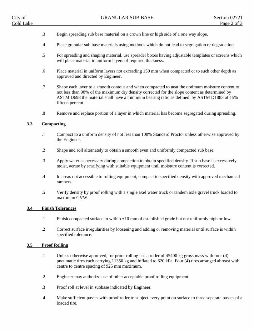
City of GRANULAR SUB BASE Section 02721
Cold Lake Page 2 of 3
.3 Begin spreading sub base material on a crown line or high side of a one way slope.
.4 Place granular sub base materials using methods which do not lead to segregation or degradation.
.5 For spreading and shaping material, use spreader boxes having adjustable templates or screens which
will place material in uniform layers of required thickness.
.6 Place material in uniform layers not exceeding 150 mm when compacted or to such other depth as
approved and directed by Engineer.
.7 Shape each layer to a smooth contour and when compacted to neat the optimum moisture content to
not less than 98% of the maximum dry density corrected for the slope content as determined by
ASTM D698 the material shall have a minimum bearing ratio as defined by ASTM D1883 of 15%
fifteen percent.
.8 Remove and replace portion of a layer in which material has become segregated during spreading.
3.3 Compacting
.1 Compact to a uniform density of not less than 100% Standard Proctor unless otherwise approved by
the Engineer.
.2 Shape and roll alternately to obtain a smooth even and uniformly compacted sub base.
.3 Apply water as necessary during compaction to obtain specified density. If sub base is excessively
moist, aerate by scarifying with suitable equipment until moisture content is corrected.
.4 In areas not accessible to rolling equipment, compact to specified density with approved mechanical
tampers.
.5 Verify density by proof rolling with a single axel water truck or tandem axle gravel truck loaded to
maximum GVW.
3.4 Finish Tolerances
.1 Finish compacted surface to within ±10 mm of established grade but not uniformly high or low.
.2 Correct surface irregularities by loosening and adding or removing material until surface is within
specified tolerance.
3.5 Proof Rolling
.1 Unless otherwise approved, for proof rolling use a roller of 45400 kg gross mass with four (4)
pneumatic tires each carrying 11350 kg and inflated to 620 kPa. Four (4) tires arranged abreast with
centre to centre spacing of 925 mm maximum.
.2 Engineer may authorize use of other acceptable proof rolling equipment.
.3 Proof roll at level in subbase indicated by Engineer.
.4 Make sufficient passes with proof roller to subject every point on surface to three separate passes of a
loaded tire.

City of GRANULAR SUB BASE Section 02721
Cold Lake Page 3 of 3 .5 Where proof rolling reveals areas of defective sub grade or sub base remove to depth and extent
directed and replace with new materials to requirements of Section 02317 and this Section at no extra
cost to owner.
3.6 Maintenance
.1 Maintain finished sub base in condition conforming to this section until succeeding base is
constructed or until granular subbase is accepted by Engineer.

City of GRANULAR BASE Section 02723
Cold Lake Page 1 of 2
1. GENERAL
This section specifies requirements for supplying, producing, placing and compacting crushed gravel granular base
to lines, grades and typical cross sections indicated on plans or as directed by Engineer.
1.1 Related Work
.1 Roadway excavation, backfill and sub grade preparation Section 02317
.2 Granular sub base Section 02721
1.2 Definitions
.1 Base: Design depth of granular base constructed immediately on sub base and prior to asphaltic
pavement.
1.3 Measurement for Payment
.1 Granular base to be measured in square meters of compacted material for the depth specified and
incorporated into work in accordance with design. Unit price bid shall be full compensation for all
work involved in supplying granular base and installing as described in Clause 3 – Execution of this
section.
2. PRODUCTS
.1 Granular base shall meet the following gradation when tested to ASTM C136 and ASTM C117, and
give a smooth curve without sharp breaks when plotted on a semi-long grading chart:
Sieve Size
(mm)
Percent Passing
(by weight)
20 100
12.5 64-100
5 36-72
1.25 12-42
0.35 4-22
0.08 3-8
.2 At least 40 percent by weight of material retained on the5, 000 sieve shall have two or more fractured
faces.
.3 Do not place granular base until finished sub base or sub grade surface is inspected by Engineer.
3. EXECUTION
.1 Inspection of Underlying Sub base or Sub grade
.1 Do not place granular base until finished sub base or sub grade surface is inspected by Engineer.
.2 Placing
.1 Place material only on a clean unfrozen surface, properly shaped and compacted and free from snow
and ice.
.2 Begin spreading base material on a crown line or on high side of a one way slope.
.3 Place using methods which do not lead to segregation or degradation of aggregate.

City of GRANULAR BASE Section 02723
Cold Lake Page 2 of 2
.4 For spreading and shaping material, use spreader boxes having adjustable templates or screens which
will place material in uniform layers of required thickness.
.5 Place material in uniform layers not exceeding 150 mm when compacted or to such other depth as
approved by Engineer.
.6 Shape each layer to a smooth contour and compact to specified density before succeeding layer is
placed.
.7 Remove and replace that portion of a layer in which material becomes segregated during spreading.
.3 Compacting
.1 When compacted near optimum content to not less than 100% of the maximum dry density corrected
for the stone content as determined by ASTM D698 the material shall have a minimum bearing ratio
as defined by ASTM D1883 of fifty-five percent (55%)
.2 Shape and roll alternately to obtain a smooth even and uniformly compacted base.
.3 Apply water as necessary during compacting to obtain specified density. If material is excessively
moist, aerate by scarifying with suitable equipment until moisture content is corrected.
.4 In areas not accessible to rolling equipment, compact to specified density with approved mechanical
tampers.
.4 Finish Tolerances
.1 Finished base surface shall be within ±10 mm of established grade but not uniformly high or low.
.2 Correct surface irregularities by loosening and adding or removing material until surface is within
specified tolerances.
.5 Proof Rolling
.1 For proof rolling use a roller of 45400 kg gross mass with four (4) pneumatic tires each carrying
11350 kg and inflated to 621 kPa. Four (4) tires arranged abreast with centre to centre spacing of
915 mm maximum.
.2 Engineer may authorize use of other acceptable proof rolling equipment.
.3 Proof roll top of base upon completion of fine grading and compaction.
.4 Make sufficient passes with proof roller to subject every point on surface to three (3) separate passes
of a loaded tire.
.5 Where proof rolling reveals defective base or sub base, remove defective materials to depth and
extend directed and replace with new materials to requirement of Section 02317, 02721, and this
Section at no extra cost to owner.
.6 Maintenance
.1 Maintain finished base in a condition conforming to this section until succeeding material is applied
or until acceptance by Engineer.

City of HOT MIX ASPHALTIC PAVING Section 02741
Cold Lake Page 1 of 1
1. GENERAL
This section specifies requirements for producing and placing hot mix asphalt concrete including supply of
aggregates and bituminous binder.
.1 Related Work
.1 Asphalt Prime Coat Section 02745
.2 Painted Pavement Markings Section 02761
.3 Plastic Pavement Markings Section 02762
.2 Definitions
.1 Overlay: Paving over an existing pavement for rehabilitation purposes and not as part of staged
paving.
.2 Staged Paving: Paving where a lift or lifts that form part of the total pavement structure are deferred
to a future date.
.3 Measurement for Payment
.1 Asphalt concrete paving to be measured in square meters. Unit price bid shall be full compensation
for all work involved in supplying asphaltic concrete and installing as described in Clause 3 –
Execution of this Section. Asphalt concrete required as leveling course in addition to the specified
depth will be measured in tonnes.
.2 Payment will be subject to the unit price adjustments for density and thickness as defined in
Section 2.

City of HOT MIX ASPHALT PAVEMENT Section 02742
Cold Lake Page 1 of 9
1.0 GENERAL
.1 Samples
.1 At least 2 weeks prior to commencing work, inform Engineer of proposed source of aggregate
materials.
.2 The Contractor shall submit asphalt concrete mix design based on the Marshall Method and trial mix
test results to the Engineer for review at least 2 weeks prior to commencing work. The Contractor
shall provide a sieve analysis of the aggregate material for the Engineer's review.
.2 Definitions
.1 Overlay: Paving over an existing pavement for rehabilitation purposes and not as part of staged
paving.
.2 Staged Paving: Paving where a lift or lifts that form part of the total pavement structure are deferred
to a future date.
.3 Mix Types: Mixes are designated according to use as follows:
.1 Surface (ACS): Surface course for freeways, arterials and industrial/ commercial streets.
.2 Base (ACB): Base course for freeways, arterials, industrial/ commercial and collectors.
.3 Residential (ACR): Residential and collector streets.
.4 Overlay (ACO): Thin overlay on arterial and collector streets.
.3 Measurement for Payment
.1 Hot mix asphalt pavement will not be measured for payment but shall be included in the relevant unit
rate where hot mix asphalt is required.
.4 Submissions
.1 Asphalt concrete mix design and aggregate material shall be submitted to the Engineer before
being used. Aggregate shall be tested for detrimental matter in coarse aggregate.
.2 Preliminary review of the aggregate as represented by the samples shall not constitute general
acceptance of all material in the deposit or source of supply. Materials may be considered unsuitable
even though particle sizes are within the limits of the gradation sizes required, if particle shapes are
thin or elongated or any other characteristic precludes satisfactory compaction or if the material fails
to provide a pavement suitable for traffic. Rejected material will not be paid for. The Engineer has
the right to request additional testing if there are any concerns with the proposed aggregate mix
design.
2.0 PRODUCTS
.1 Mix Type
.1 Mix type shall be ACR with a required minimum density of 97% Marshall Density.
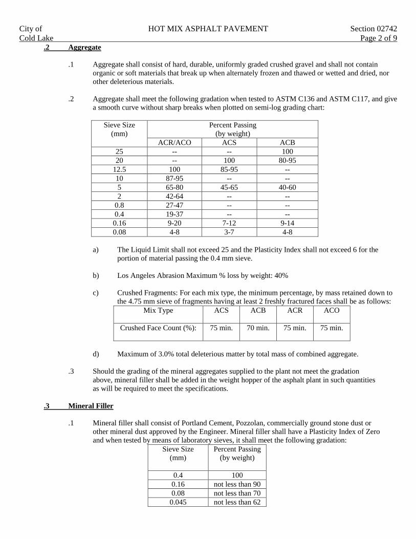
City of HOT MIX ASPHALT PAVEMENT Section 02742
Cold Lake Page 2 of 9 .2 Aggregate
.1 Aggregate shall consist of hard, durable, uniformly graded crushed gravel and shall not contain
organic or soft materials that break up when alternately frozen and thawed or wetted and dried, nor
other deleterious materials.
.2 Aggregate shall meet the following gradation when tested to ASTM C136 and ASTM C117, and give
a smooth curve without sharp breaks when plotted on semi-log grading chart:
Sieve Size
(mm)
Percent Passing
(by weight)
ACR/ACO ACS ACB
25 -- -- 100
20 -- 100 80-95
12.5 100 85-95 --
10 87-95 -- --
5 65-80 45-65 40-60
2 42-64 -- --
0.8 27-47 -- --
0.4 19-37 -- --
0.16 9-20 7-12 9-14
0.08 4-8 3-7 4-8
a) The Liquid Limit shall not exceed 25 and the Plasticity Index shall not exceed 6 for the
portion of material passing the 0.4 mm sieve.
b) Los Angeles Abrasion Maximum % loss by weight: 40%
c) Crushed Fragments: For each mix type, the minimum percentage, by mass retained down to
the 4.75 mm sieve of fragments having at least 2 freshly fractured faces shall be as follows:
Mix Type ACS ACB ACR ACO
Crushed Face Count (%): 75 min. 70 min. 75 min. 75 min.
d) Maximum of 3.0% total deleterious matter by total mass of combined aggregate.
.3 Should the grading of the mineral aggregates supplied to the plant not meet the gradation
above, mineral filler shall be added in the weight hopper of the asphalt plant in such quantities
as will be required to meet the specifications.
.3 Mineral Filler
.1 Mineral filler shall consist of Portland Cement, Pozzolan, commercially ground stone dust or
other mineral dust approved by the Engineer. Mineral filler shall have a Plasticity Index of Zero
and when tested by means of laboratory sieves, it shall meet the following gradation:
Sieve Size
(mm)
Percent Passing
(by weight)
0.4 100
0.16 not less than 90
0.08 not less than 70
0.045 not less than 62

City of HOT MIX ASPHALT PAVEMENT Section 02742
Cold Lake Page 3 of 9
.2 Mineral filler to be dry and free flowing when added to aggregate.
.4 Asphaltic Binder
.1 The asphaltic binder shall be uniform in character, shall not foam when heated to 175°C and
shall meet the following requirements:
.1 Designation .................................................................................................... A/C 150/200
.2 Penetration (ASTM D5) under 100 g for 5 sec. at 25°C .............................…...150 to 200
.3 Flash Point (ASTM D92) filled or unfilled greater than...........................................190°C
.4 Ductility (ASTM D113) strain rate of 5 cm.sec. at 25°C greater than................100(+) cm
.5 Solubility in CCl4 (unfilled)................................................................................ 99.0(+)%
.6 Kinematic Viscosity in Centistokes at 135°C .......................................................... 150(+)
.7 Thin Film Oven Test Penetration under 100 g for 5 sec. at 25°C………………… 45(+)%
.5 Mix Design
.1 From the aggregate and asphalt cement samples; the testing laboratory shall prepare a design mix to
produce the following criteria:
Mix Type ACS ACB ACR ACO
Max. Aggregate Size, mm 20 25 12.5 12.5
No. of Blows 75 75 50 75
Minimum Stability, N 6,700 6,700 4,500 6,700
Minimum Retained Stability, % 75 75 75 75
Flow Value, 0.254 mm Unit 6-12 6-12 8-16 6-12
.2 The Marshall Stability Value and the Flow Index shall be tested in accordance with the current issue
of ASTM D1559 for Resistance to Plastic Flows of Bituminous Mixtures.
.3 The Percentage Voids and Percentage Aggregate Voids Filled with Asphalt shall be determine
according to the Marshall Method of Mix Design for Hot Mix Asphalt Paving, as set out in the latest
edition of the Asphalt Institute Manual Series.
3.0 EXECUTION
.1 Preparation
.1 Patch and correct depressions and other irregularities to approval of the Engineer before beginning
paving operations. Prior to laying mix, clean surfaces of loose and foreign material and apply primer
coat or tack coat in accordance with Section 32 12 14 - Asphalt Prime Coat or Section 32 12 15
Asphalt Tack Coat.
.2 Mix Tolerances
.1 All mixture furnished shall conform to the job mix formula within the range of tolerance
specified:
.1 Aggregate Material Passing (mm) Percent by Weight
5 Sieve ±6
0.8 Sieve ±4
0.08 Sieve ±1.5
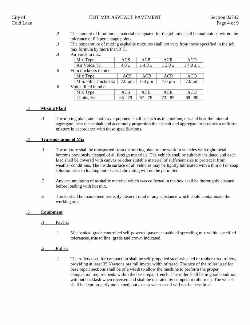
City of HOT MIX ASPHALT PAVEMENT Section 02742
Cold Lake Page 4 of 9
.2 The amount of bituminous material designated for the job mix shall be maintained within the
tolerance of 0.3 percentage points.
.3 The temperature of mixing asphaltic mixtures shall not vary from those specified in the job
mix formula by more than 9˚C.
.4 Air voids in mix:
Mix Type ACS ACB ACR ACO
Air Voids, %: 4.0 ± 1 4.0 ± 1 3.0 ± 1 4.0 ± 1
.5 Film thickness in mix:
.6 Voids filled in mix:
Mix Type ACS ACB ACR ACO
Limits, %: 65 - 78 67 - 78 73 - 85 68 - 80
.3 Mixing Plant
.1 The mixing plant and auxiliary equipment shall be such as to combine, dry and heat the mineral
aggregate, heat the asphalt and accurately proportion the asphalt and aggregate to produce a uniform
mixture in accordance with these specifications.
.4 Transportation of Mix
.1 The mixture shall be transported from the mixing plant to the work in vehicles with tight metal
bottoms previously cleaned of all foreign materials. The vehicle shall be suitably insulated and each
load shall be covered with canvas or other suitable material of sufficient size to protect it from
weather conditions. The inside surface of all vehicles may be lightly lubricated with a thin oil or soap
solution prior to loading but excess lubricating will not be permitted.
.2 Any accumulation of asphaltic material which was collected in the box shall be thoroughly cleaned
before loading with hot mix.
.3 Trucks shall be maintained perfectly clean of mud or any substance which could contaminate the
working area.
.5 Equipment
.1 Pavers:
.1 Mechanical grade controlled self-powered pavers capable of spreading mix within specified
tolerances, true to line, grade and crown indicated.
.2 Roller:
.1 The rollers used for compaction shall be self-propelled steel-wheeled or rubber-tired rollers,
providing at least 35 Newtons per millimeter width of tread. The size of the roller used for
base repair sections shall be of a width to allow the machine to perform the proper
compaction requirements within the base repair trench. The roller shall be in good condition
without backlash when reversed and shall be operated by competent rollermen. The wheels
shall be kept properly moistened, but excess water or oil will not be permitted.
Mix Type ACS ACB ACR ACO
Min. Film Thickness: 7.0 µm 6.0 µm 7.0 µm 7.0 µm

City of HOT MIX ASPHALT PAVEMENT Section 02742
Cold Lake Page 5 of 9
.3 Hand Tools:
.1 Lutes or rakes with covered teeth for spreading and finishing operations.
.6 Placing
.1 Obtain Engineer's approval of base and existing surface and tack coat and prime coat prior to placing
asphalt. Asphaltic concrete shall be constructed in layers to obtain the following minimum and
maximum compacted thickness:
Mix Type Minimum (mm) Maximum (mm)
ACS 40 75
ACR 25 75
ACB 50 125
.2 Place asphalt concrete to thicknesses, grades and lines indicated or directed by Engineer.
.3 Placing Conditions:
.1 Place asphalt mixtures only when air temperature is above 2°C.
.2 When temperature of surface on which material is to be placed falls below 10°C,
provide extra rollers as necessary to obtain required compaction before cooling.
.3 Do not place hot mix asphalt when pools of standing water exist on surface to be
paved, during rain, or when surface is damp.
.4 Mixtures shall be spread at temperatures which, when measured in the hopper of the
spreader, are not lower than 125°C or higher than 150°C.
.5 In small areas where the use of mechanical finishing equipment is not practical, the mix may
be spread and finished by hand, if so directed by the Engineer. The material shall be distributed
uniformly to avoid segregation of the coarse and fine aggregates. Broadcasting of material shall not
be permitted. During the spreading operation, all material shall be thoroughly loosened and
uniformly distributed by lutes or rakes. Material that has formed into lumps and does not break down
readily shall be rejected.
.7 Rolling and Compaction
.1 Before rolling is started, the surface shall be checked, inequalities in depth adjusted and fat
spots or sandy accumulations replaced and irregularities in alignment or grade along the outside edge
shall be corrected.
.2 The rollers must be kept in continuous operation as nearly as practicable and all parts of the
pavement shall receive substantially the same compaction. Rolling shall be done at a maximum
speed of 5 km per hour.
.3 At least one roller shall be used for every 40 tonnes of asphaltic concrete laid per hour.
Rolling shall start as soon as the pavement will bear the roller without checking or undue
displacement, working from the low part or edge to the high part or edge continuously until no
roller marks are left in the finished surface and no further compaction is possible. Where
width permits the pavement shall be rolled diagonally in two directions. At all curbs, manholes
and other appurtenances, and at all locations not accessible to the rollers, hand tampers shall
be used to produce the same density as provided by the roller. Where the asphaltic concrete
is laid in more than one lift, each lift shall be so compacted.

City of HOT MIX ASPHALT PAVEMENT Section 02742
Cold Lake Page 6 of 9
.4 Required Density: Each mat of hot mix placed shall be compacted to the following minimum
density (% of Marshall density) for the type of paving, or as indicated in Special Provisions.
Minimum Density Type of Paving
98% New Paving and all stages in staged paving except 2nd stage
residential #44 mm.
96% Second stage residential mat 40 mm thick or less.
97% Lane paving.
97% Overlay more than 40mm thick.
96% Overlay 40 mm thick or less.
.
.8 Joints
.1 The mixture shall be laid so that all longitudinal joints are made while the first mat of the two
being laid is still hot.
.2 A narrow strip along the edge of a mat which is joined with another asphalt mat shall be left
without rolling until the adjoining mat has been placed against it. The joint which is formed
shall be rolled immediately after the adjacent mat has been placed to ensure a bonding of the
material while the asphalt is still hot.
.3 Transverse joints shall be carefully constructed and thoroughly compacted to provide a smooth-
riding surface. Joints shall be straight-edged to assure smoothness and true alignment and shall be
offset at least one meter from joints of adjacent mats. The vertical face shall be treated with freshly
laid mixture raked against it, tamped with hot tampers and rolled. Heat shall be used as necessary to
ensure a proper bond.
.4 All concrete or metal structures such as gutters, manholes, etc. shall be painted with an approved
bituminous material prior to placing the plant mix.
.9 Finish
.1 The finished pavement shall be true to the required profile and cross-section. Tests of pavement
profile and thickness shall be made after the first layer of asphalt has been placed, and depressions or
bumps in excess of 5 mm shall be corrected. The allowable tolerance for finished pavement shall be
±5 mm, and the surface shall show no depressions or bumps exceeding 3 mm under a straight-edge
3 m long placed parallel to the road centerline.
.2 Finished surface shall have a tightly knit texture free of visible signs of poor workmanship such as,
but not limited to:
.1 Segregation;
.2 Areas exhibiting excess or insufficient asphalt;
.3 Improper matching of longitudinal and transverse joints;
.4 Roller marks, cracking, or tearing;
If surface and grade tolerances are exceeded, or if surface texture is not met, grind down and
resurface defective areas as required by the Engineer.

City of HOT MIX ASPHALT PAVEMENT Section 02742
Cold Lake Page 7 of 9
.10 Defective Work
.1 Correct irregularities which develop before completion of rolling by loosening surface mix and
removing or adding material as required. If irregularities or defects remain after final compaction,
remove surface course promptly and lay new material to form a true and even surface and compact
immediately to specified density.
.2 Repair areas showing checking or hairline cracking.
.11 Testing and Inspection
.1 The Engineer or his representative shall retain core samples from the completed pavement, from
which depth of pavement and density tests shall be made.
.2 One core shall be taken for approximately every 1,000 m2 of asphalt or at least once each day
during placing operations. The following tests shall be carried out:
.1 Marshall stability (test for resistance of plastic flow of bituminous mixtures) using
Marshall Apparatus as per ASTM D1559.
.2 Sieve analysis of extracted aggregates in accordance with ASTM C136 and entire
washed sample in accordance with ASTM C117.
.3 Bulk specific gravity of compacted mixtures in accordance with ASTM D2726.
.4 Bitumen content of paving mixtures in accordance with ASTM D2172.
.5 Percent voids in the mineral aggregates (VMA) is to be calculated on the basis of
ASTM D2726 Bulk Specific Gravity of the aggregate.
.6 Air voids in compacted mix in accordance with ASTM D3203.
.3 The Contractor shall repair all test holes with fresh, hot mix asphaltic concrete mixture, and
thoroughly compact it to the required density with no additional compensation.
.12 Penalties
.1 Thickness:
.1 If a deficiency in the thickness is found, two more cores shall be taken in the area, and the
average thickness of the three cores shall represent the area. The Contract Unit Price shall be
adjusted as follows for areas deficient in thickness.
.1 No payment shall be made for asphaltic surface course deficient in thickness by 13
mm or more.
.2 If the surface course id found deficient by more than 3 mm but less than 13 mm, then
the adjusted unit price shall have the same ratio to the contract unit price that the
square of the average thickness found has to the square of the specified thickness.
.2 No price adjustment shall be made for surface course found to be deficient by less than 3 mm
or any thicker than specified.

City of HOT MIX ASPHALT PAVEMENT Section 02742
Cold Lake Page 8 of 9
.2 Density:
.1 The cores will be used to determine density. If any test fails to meet the density specified,
two more cores shall be taken in the area. If the densities are less than specified, the
Contract Unit Price shall be adjusted as follows:
ASPHALT PAY FACTORS
98% Required 97% Required 96% Required
Actual Density
%
Pay Factor
%
Actual Density
%
Pay Factor
%
Actual Density
%
Pay Factor
%
98.0 100.0 97.0 100.0 96.0 100.0
97.9 99.9 96.9 99.9 95.9 99.7
97.8 99.8 96.8 99.7 95.8 99.3
97.7 99.6 96.7 99.4 95.7 98.9
97.6 99.4 96.6 99.1 95.6 98.4
97.5 99.1 96.5 98.7 95.5 97.8
97.4 98.7 96.4 98.2 95.4 97.1
97.3 98.3 96.3 97.7 95.3 96.4
97.2 97.8 96.2 97.1 95.2 95.6
97.1 97.2 96.1 96.3 95.1 94.6
97.0 96.5 96.0 95.5 95.0 93.4
96.9 95.8 95.9 94.6 94.9 92.2
96.8 95.0 95.8 93.6 94.8 90.7
96.7 94.2 95.7 92.5 94.7 89.1
96.6 93.3 95.6 91.3 94.6 97.3
96.5 92.3 95.5 89.9 64.5 85.1
96.4 91.1 95.4 88.4 94.4 82.6
96.3 89.8 95.3 86.7 94.3 79.5
96.2 88.5 95.2 84.8 94.2 75.5
96.1 97.1 95.1 82.7 94.1 69.7
96.0 85.5 95.0 80.3 94.0 60.0
95.9 83.8 94.9 77.6 Under 94.0 Reject
95.8 82.0 94.8 74.3
95.7 80.0 94.7 70.6
95.5 75.4 94.5 60.0
95.4 73.0 Under 94.5 Reject
95.3 70.3
95.2 67.2
95.1 63.7
95.0 60.0
Under 95.0 Reject
Actual Density = % of Marshall density.
Pay Factor = % of contract price.

City of HOT MIX ASPHALT PAVEMENT Section 02742
Cold Lake Page 9 of 9
.13 Acceptance
.1 Locations shall be cleared of all excess material resulting from the paving operation and any damage
caused by the Contractor shall be repaired to the Engineer's satisfaction within 3 days of the date of
completion of the street or lane. Failure to cleanup or repair damage may result in other crews
undertaking this work without notice to the Contractor and deducting the costs from money due to
the Contractor.
.2 No traffic shall be allowed on the finished surface until it has cooled to atmospheric temperature.

City of ASPHALT PRIME AND TACK COATS Section 02745
Cold Lake Page 1 of 3
1. GENERAL
This section specifies requirements for furnishing and applying asphalt to an absorbent surface.
1.1 Related Work
.1 Granular Base Section 02723
.2 Hot Mix Asphaltic Concrete Paving Section 02741
.3 Asphaltic Concrete Overlay Paving Section 02786
1.2 Samples
.1 If requested submit to Engineer one 4 liter container of asphalt material proposed for use in work at
least two (2) weeks prior to commencing operations.
1.3 Measurement for Payment
.1 Asphalt prime coat to be measured in square meters at the rate of application specified, based on
nominal pavement widths shown on drawings. Payment shall include the supply of materials,
preparation of surface, brooming or sweeping the surface, application, sand blotting, including the
supply of sand, maintaining the treated surface and the supply of all tools and incidentals to complete
the work.
. 2. PRODUCTS
.1 Prime Coat
.1 The Contractors choice of SEP-1, SEP-2 or SS-1 for application through August 31 each
season. The contractors choice of MC-30, SEP-1, SEP-2 or SS-1 for application after
August 31 each season.
.2 Sand used for the blotting of excess asphalt due to prime shall be supplied by the contractor.
.2 Tack Coat
.1 The bituminous material for tacking the existing asphalt surface shall be liquid asphalt. The
asphalt types may vary from rapid curing (RC type RC-30 to RC–250: from slow setting
(SS) type SS-1 to SS-H, depending on conditions to suit the base and time of season.
.3 Sand Blotter
.1 The materials for sand cover shall consist of clean granular mineral material reviewed by the
Engineer, all of which shall pass a 5,000 sieve.

City of ASPHALT PRIME AND TACK COATS Section 02745
Cold Lake Page 2 of 3
3. EXECUTION
3.1 Asphalt Distributor
.1 Cleaning equipment shall consist of power brooms, flushers and whatever hand scrapers may be
necessary to remove all foreign material.
.1 Provide distributor so designed equipped maintained and operated that asphalt material at even heat
may be applied uniformly on variable widths of surface up to 5.6m at readily determined and
controlled rates from 0.2 to 5.4 liters per minute (L/m), with uniform pressure, and with an allowable
variation from any specified rate not to exceed 0.1 L/m.
.2 Capable of distributing asphalt material in a uniform spray without atomization at rate specified and
temperature required.
.3 Pump to operate by a separate power unit independent of truck power unit.
.4 Equipped with an easily read, accurate device which registers temperature of liquid in reservoir.
.5 Equipped with accurate volume measuring devices or a calibrated tank.
.6 If provided with heating attachments the distributor shall be so equipped and operated that the
asphaltic material shall be circulated or agitated throughout the entire heating process.
3.2 Preparation
.1 Shape surface to proper cross section.
.2 Have surface approved by engineer before applying prime material.
.3 Engineer may authorize a light spraying of water to moisten an excessively dry and dusty surface to
aid penetration of asphalt prime.
3.3 Application
.1 Upon the prepared surface the asphalt shall be applied uniformly at a rate of from
0.50 to 1.75 liters/square meter (L/m2) for asphalt primer, and at a rate of from 0.3 to 0.90 L/m2 for
tack coat. The asphalt primer or tack coat shall be applied only when the surface is dry or slightly
damp, or only when the air temperature in the shade is above 10°C.
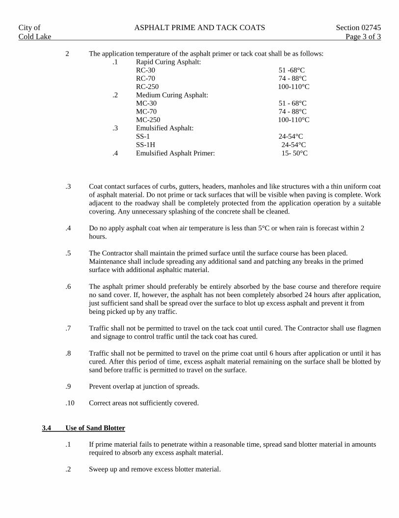
City of ASPHALT PRIME AND TACK COATS Section 02745
Cold Lake Page 3 of 3
2 The application temperature of the asphalt primer or tack coat shall be as follows:
.1 Rapid Curing Asphalt:
RC-30 51 -68°C
RC-70 74 - 88°C
RC-250 100-110°C
.2 Medium Curing Asphalt:
MC-30 51 - 68°C
MC-70 74 - 88°C
MC-250 100-110°C
.3 Emulsified Asphalt:
SS-1 24-54°C
SS-1H 24-54°C
.4 Emulsified Asphalt Primer: 15- 50°C
.3 Coat contact surfaces of curbs, gutters, headers, manholes and like structures with a thin uniform coat
of asphalt material. Do not prime or tack surfaces that will be visible when paving is complete. Work
adjacent to the roadway shall be completely protected from the application operation by a suitable
covering. Any unnecessary splashing of the concrete shall be cleaned.
.4 Do no apply asphalt coat when air temperature is less than 5°C or when rain is forecast within 2
hours.
.5 The Contractor shall maintain the primed surface until the surface course has been placed.
Maintenance shall include spreading any additional sand and patching any breaks in the primed
surface with additional asphaltic material.
.6 The asphalt primer should preferably be entirely absorbed by the base course and therefore require
no sand cover. If, however, the asphalt has not been completely absorbed 24 hours after application,
just sufficient sand shall be spread over the surface to blot up excess asphalt and prevent it from
being picked up by any traffic.
.7 Traffic shall not be permitted to travel on the tack coat until cured. The Contractor shall use flagmen
and signage to control traffic until the tack coat has cured.
.8 Traffic shall not be permitted to travel on the prime coat until 6 hours after application or until it has
cured. After this period of time, excess asphalt material remaining on the surface shall be blotted by
sand before traffic is permitted to travel on the surface.
.9 Prevent overlap at junction of spreads.
.10 Correct areas not sufficiently covered.
3.4 Use of Sand Blotter
.1 If prime material fails to penetrate within a reasonable time, spread sand blotter material in amounts
required to absorb any excess asphalt material.
.2 Sweep up and remove excess blotter material.

City of ASPHALTIC CONCRETE CURBS Section 02747
Cold Lake Page 1 of 2
1. GENERAL
This section specifies requirements for construction of asphalt curbs on an existing asphalt surface.
1.1 Measurement for Payment.
.1 Asphaltic concrete pavement curb will be measured in linear meters measured along face of curb.
.2 Cleaning pavement surfaces to Section 02966.
.3 Tack coat to Section 02745.
2. MATERIAL
2.1 Asphaltic Hot Mix
.1 Asphaltic hot mix to Section 02741 – Class 12.5.
.2 Normal Portland Cement to be added to mix in amounts not less than 80kg of cement to 1000 kg of
hot mix.
.3 Asphalt binder to be CGSB15-GP-3M, grade 85/100 or 120/150. binder content to be 6% to 8.5%.
.4 Air void content to be 5% to 10%.
2.2 Tack Coat
.1 Tack coat to Section 02745.
3. EXECUTION
3.1 Tack coat
.1 Apply with hand sprayer, high film of tack coat to surface beneath curb to be installed.
3.2 Placing of Curb Mix
.1 To be placed using a slip form spreader to cross section shown on drawing.
.2 Asphalt temperature range 125º C to 150º C during placement.
3.3 Hand placing of Curb Mix
.1 In areas not machine accessible, place curb mix by hand using wood or metal forms to design cross
section.
.2 Remove form when proper shape of material can be maintained.
3.4 Joints
.1 Curb construction to be continuous with minimum joints.
.2 Joint to be carefully made.
City of ASPHALTIC CONCRETE CURBS Section 02747
Cold Lake Page 2 of 2
.3 Paint end of joint with tack coat material before placing fresh curb mix.

City of RESHAPING GRANULAR ROADBED Section 02748
Cold Lake Page 1 of 2
1. GENERAL
This section specifies requirements for scarifying and reshaping of existing granular roads and lanes with addition of
new granular base material where required to lines, grades and typical cross section as indicated or as established by
Engineer.
1.1 Related Work
.1 Roadway Excavation, Backfill, and Subgrade Preparation Section 02317
.2 Granular Base Section 02723
1.2 Measurement for Payment
.1 Removal of clay and other deleterious surface material shall be measured in cubic meters of material
wasted based on truck box measure. Truck box volume to be calculated by the Engineer to the
nearest 0.1 m³ based on the struck measure of the truck box.
.2 Reconditioning of gravel lane to include scarifying, reshaping and compaction of existing roadbed,
and shall be measured in square meters.
.3 New granular base material shall be measured in tones of material incorporated in work and based on
weigh tickets as submitted to engineer with each load installed.
2. PRODUCTS
2.1 Materials
.1 Granular base aggregate to be 20 mm crushed gravel.
3. EXECUTION
3.1 Waste Excavation
.1 Remove contaminated gravel, clay and other deleterious material and haul to designated waste
disposal site.
3.2 Scarifying and Reshaping
.1 Scarify remaining granular base material as directed by Engineer to maximum depth of remaining
granular base material or 100 mm whichever is least.
.2 Blade and trim scarified material to elevation and cross section dimensions indicated or as directed
by Engineer.
.3 Where a deficiency of material exists, add and blend in new granular base material as directed by
Engineer.
3.3 Compacting
.1 Compact to a density not less than 100% Standard Proctor Density.
.2 Shape and roll alternately to obtain smooth, even and uniformly compacted base.

City of RESHAPING GRANULAR ROADBED Section 02748
Cold Lake Page 2 of 2
.3 Apply water as necessary during compaction to obtain specified density. If material is excessively
moist, aerate by scarifying with suitable equipment until moisture content is corrected.
.4 In areas not accessible to rolling equipment, compact to specified density with mechanical tampers
approved by Engineer.
3.4 Tolerance
.1 Reshaped compacted surface shall be within ± 10 mm of elevation as indicated.

City of PAVEMENT MARKINGS GENERAL Section 02760
Cold Lake Page 1 of 7
1. GENERAL
This section specifies the general requirements for pavement markings regardless of the type of pavement marking
used. Deviations from these general requirements will be covered in the specific requirements for each material.
The Work shall consist of furnishing all materials, equipment and labor necessary for the required pavement
preparation and application of uniformly retro reflective pavement marking materials in accordance with the plans or
as described herein. All pavement markings shall conform with the Manual of Uniform Traffic Control Devices for
Canada (Current Edition).
1.1 Related Work
.1 Painted Pavement Markings Section 02761
.2 Thermoplastic Pavement Markings Section 02762
.3 Spray Pavement Markings Section 02763
.4 Cold Plastic Markings Section 02764
.5 Pavement Marking Removal Section 02767
.6 Pavement Surface Cleaning Section 02966
1.2 References
.1 ASTM D4060: Test Method for Abrasion Resistance of Organic Coating by Taber Abrasion.
.2 ASTM D256: Test Method for Impact Resistance of Plastics and Electrical Insulating Materials.
.3 ASTM D570: Test Method for Water Absorption of Plastics.
.4 ASTM E28: Test Method for Softening Point by Ring and Ball Apparatus.
.5 ASTM E1347: Test Method for Directional Reflectance 45º 0º, of Opaque Specimens by Broadband
Filter Reflectometry.
1.3 Definitions
.1 Plastic pavement marking material: means any type of paving marking material, excluding paint,
consisting of various materials that harden and retain their shape after being applied to the pavement
or concrete surface.
1.4 Samples
.1 If requested by Engineer, submit the following material sample quantities at least four 4 weeks prior
to commencing work.
.1 Two 1 l samples of each type of paint.
.2 One kg. of sample of glass beads.
.3 Sampling to CGSB 1 – GP-71.
.2 Mark samples with name of product and its location, paint manufacturer’s name and address, name
of paint, CGSB specification number, formulation number and batch number.

City of PAVEMENT MARKINGS GENERAL Section 02760
Cold Lake Page 2 of 7
1.5 Measurement for Payment
.1 Lines shall be measured in lineal meters of material installed for each type of line installed. Gaps
between line segments are not measured.
.2 Pavement marking including reflective glass beads shall be measured in lineal meters of material
installed.
.3 No additional payment will be made for the supply of pavement marking material and reflective
glass beads
.4 Symbols and letters will be measured in specified units.
.5 Removal of pavement markings will be in specified units.
Pavement marking will be measured complete in place in the units designated. Line quantities will be the
length of completed marking, excluding the gaps.
All work performed and measured as prescribed above will be paid for as provided in the respective items for
each type of pavement marking material supplied and installed. Payment shall include all labor, equipment
and materials necessary to complete the work.
2. PRODUCTS
2.1 Materials
.1 Marking materials shall be a formulation, identified by a manufacturer’s code number, prequalified
by and have the same composition as the prequalified marking material. Acceptance criteria for new
plastic pavement marking materials are included in Clause 2.2 of this Section.
.2 When plastic pavement marking are to be installed, the contractor and sub contractor shall provide
written evidence that he has a minimum of three (3) years successful experience supplying and
installing plastic pavement markings as specified in Sections 02762, 02763 and 02764 and be
acceptable to the owner.
.3 Pavement marking materials shall conform to the following:
Traffic paint Section 02761.
Thermoplastic Pavement Markings Section 02762.
Spray Pavement Markings Section 02763.
Cold Plastic Markings Section 02764.
A Material Safety Data Sheet for each material, including resin, catalyst, activator, glass beads and
cleaning solvent to be used on the project shall be furnished by the Contractor to the Engineer prior
to the start of work. The applicator shall maintain current Material Safety Data sheets for all
materials present with this work in an immediately accessible location.
.4 Glass Beads: Overlay type: to CGSB1-GP-74M as follows:
.1 Imperfections: Surface of spheres shall be smooth and free from film, scratches and pits. At
least 90% shall be of true spherical shape and free from milkiness dark or air inclusions and
other defects.

City of PAVEMENT MARKINGS GENERAL Section 02760
Cold Lake Page 3 of 7
.2 Index of Refraction: Liquid immersion method at 25º C may be used to determine refraction
index of glass spheres. A refractive index of 1.50 to 1.60 is required.
.3 Gradation: Spheres shall meet following gradation requirements when tested in accordance
with ASTM D-1214.
.1 Spheres included in manufacture and for surface application on of thermoplastic
material:
Sieve size (microns) % passing
850 90 – 100
300 15 – 50
180 0 – 10
.4 Beads shall show resistance to corrosion after exposure to a 1% solution (by
weight) of sulphuric acid.
2.2 Criteria for Acceptance
Plastic pavement marking materials shall be acceptable for installation on City roadways based on the
following criteria:
.1 Contractor/Supplier has installed that particular product in other cities with similar climatic
conditions.
.2 The material was installed on roadways with more than 10,000 vehicles per day and over 90% of the
marking material remained in good condition after three (3) years of service.
.3 The contractor has provided three references for the products past performance.
The Contractor shall submit the requested information for the City’s assessment of a product at least three (3) months
prior to bidding on any roadway project in the City.
Plastic pavement marking material that does not meet the above noted criteria may be considered for installation at
locations specified by the city for evaluation purposes. The material will be considered an acceptable project if 90%
of the markings remain in good condition after three (3) years of service.
3. EXECUTION
3.1 Drawing Confirmation
.1 Arrange a meeting with the Traffic Engineer to review the pavement marking drawings prior to the
commencement of pre-marking for the installation of the permanent pavement marking materials.
3.2 General
.1 Lines shall be applied as solid, dashed or dotted stripes, either singly or in combination as shown on
the drawings. The Contractor shall use an accurate dashing mechanism, which is capable of being
easily adjusted to retrace existing dashed markings or to apply new materials at the correct spacing.
Dashed lines that are to be applied over plainly visible existing dashed lines shall begin within 150
mm of the beginning of the existing dash, unless otherwise directed by the Engineer.

City of PAVEMENT MARKINGS GENERAL Section 02760
Cold Lake Page 4 of 7
.2 Gaps not marked as a result of template use for symbols and words shall be filled with marking
material after template removal.
.3 Pavement markings shall be free of uneven edges, overspray or other readily visible defects that
detract from the appearance or function of the pavement markings.
.4 Methods and equipment used for pavement preparation, marking and marking removal shall be
subject to the approval of the Engineer. Glass beads shall be kept dry during storage and prior to use.
.5 The Contractor shall furnish to the Engineer copies of current manufacturers instructions and
recommendations for application of any marking material, including primer, activator, catalyst
and/or adhesive called for in the plans.
.6 Other construction work such as shoulder paving, seeding and/or mulching shall be scheduled and
performed in a manner to avoid damage to applied pavement marking.
3.3 Storage
.1 Store pavement marking materials as per manufacturer instructions.
3.4 Site Preparation
.1 Maintain vehicular and pedestrian traffic as directed by Engineer. Provide flagmen, barricades,
flares and signing to protect workers and public.
.2 Sweep or air blow pavement surface clean and dry to Section 02966.
.3 If required, remove existing markings and repair pavement surface in accordance with Section
02767.
.4 Pre mark intended lines at a minimum off set of 150 mm. Pre mark outline of symbols. Engineer to
inspect and approve pre-marking. Any correction to pre-marking shall be at Contractors expense.
All marking shall be within 12 mm± of that specified on drawings, unless the Engineer approves
variances.
3.5 Line Types
.1 Lines shall be sharp, well defined and uniformly retroflective. The width of line applied shall be the
width specified. Fuzzy lines, excessive overspray or non uniform applications are unacceptable.
Lines shall provide proper visibility. Pavement markings that are improperly applied, located or
reflectorized shall be corrected. Lines applied with insufficient material quantities shall be properly
reapplied. Improperly located lines shall be removed in accordance with Section 02767; new lines
shall then be applied in the correct locations at the Contractors expense, including furnishing of
approved materials.

City of PAVEMENT MARKINGS GENERAL Section 02760
Cold Lake Page 5 of 7
3.6 Line Dimensions and Acceptable Pavement Marking Materials
.1 Line dimensions shall be as described in the most recent edition of the Manual of Uniform Traffic
Control Devices For Canada and any revisions thereto.
.2 Acceptable pavement marking materials for the various road classifications are as follows:
ITEM TYPE OF MATERIAL
Expressways and Arterial Roadways
1. Centre Lines Type 1
2. Edge lines Type 2 or type 3
3. Lane lines Type 1
4. Stop Bars Type 1
5. Crosswalk lines Type 1
6. Guide Lines Type 1
7. Arrows and symbols Type 2 or type 3
8. concrete bridge decks Type 2 or type 3
9. asphalt bridge decks Type 1
COLLECTOR ROADWAYS
1. Centre lines Type 2 or type 3
2. Lane lines Type 2 or type 3
3. Stop bars Type 2 or type 3
4. Crosswalk lines Type 2 or type 3
LOCAL ROADWAYS
1. Centre lines Paint
2. Stop bars Paint
3. Crosswalk lines Paint
Notes:
.1 Expressway and Arterial roadways include any portion of a Collector or Local within 50 m of an
intersecting expressway or arterial roadway.
.2 Type 1 – Thermoplastic: “Hot In-Laid” material as specified in Section 02762.
.3 Type 2 – Spray applied hybridized polymer epoxy surface material as specified in Section 02763.
.4 Type 3 – Surface applied cold plastic marking material as specified in Section 02764.
3.7 Installation
.1 Paint applications: as specified in Section 02761.
.2 Hot thermoplastic applications: as specified in Section 02762.
.3 Spray plastic applications: as specified in Section 02763.
.4 Cold plastic applications: as specified in Section 02764.
3.8 Protection and Cleanup
.1 Do not permit traffic over applied markings until directed by Engineer.

City of PAVEMENT MARKINGS GENERAL Section 02760
Cold Lake Page 6 of 7
.2 Protect surrounding areas and structures from disfiguration and damage. Repair damage as directed
by Engineer.
.3 On completion of work, clean up and leave site free of debris and waste matter.
3.9 Workmanship
.1 Faulty markings such as non straight lines, non uniform, excessive overflow, overspray etc. shall be
redone within five working days at no cost to the Owner.
3.10 Performance Life/Acceptance
.1 General
.1 A warranty period is not applicable for painted pavement markings.
.2 Plastic pavement markings shall be warranted against failure due to:
.1 Poor adhesion.
.2 Defective materials.
.3 Improper installation.
.2 Initial Acceptance of Plastic Pavement Markings
All plastic pavement markings shall have the following initial acceptance requirements:
.1 Following initial completion of all pavement marking, there will be a 180 day observation
period before initial acceptance. During the observation period, the Contractor at no
additional cost to the Owner, shall replace markings that the Engineer determines are not
performing satisfactorily due to defective materials, workmanship in manufacture or
application. At the end of the observation period, the minimum required retention percentage
by area for markings installed will be 95%.
.2 Determination of percentage retained: The percentage retained shall be calculated as the
nominal area of the strip less the area of loss divided by the nominal area and expressed as a
percentage of the nominal area.
.3 The Contractor shall be notified in writing within 30 calendar days after the 180 day
observation period if there is a failure to achieve the required percentage retained.
When such a notification is made prior to September 1, the replacement material shall be
installed during the same construction season. Replacement materials for any notification
after September 1 shall be installed prior to June 1 of the following year.
.4 Initial acceptance: Initial acceptance of the pavement marking will be:
.1 180 days after the initial completion of all pavement marking work or
.2 Upon completion of all corrective work, whichever occurs last.
The Engineer will issue a construction completion certificate for plastic pavement marking
once the initial acceptance criteria are met.

City of PAVEMENT MARKINGS GENERAL Section 02760
Cold Lake Page 7 of 7
.3 Final Acceptance/Warranty Period:
.1 The warranty period for plastic pavement markings shall be five years, commencing on
issuance of the Construction Completion Certificate for Plastic Pavement Marking.
.2 The Contractor/Subcontractor shall submit the plastic pavement marking warranty form
included in Section 00600 together with a request for the Plastic Pavement Marking
Contraction Completion Certificate following the initial observation period.
The guarantee for the plastic pavement marking material shall be subject to traffic and
normal summer and winter roadway maintenance procedures.
.3 During the warranty period, the Contractor at no additional cost to the Owner shall replace
markings that the Engineer determines are not performing satisfactorily due to defective
material’s, workmanship in manufacture or application. During the warranty period, the
minimum required retention percentage by area for markings installed will be as follows:
.1 Year one 100%
.2 Year two 95%
.3 Year three 90%
.4 Year four 85%
.5 Year five 80%
The percentage retained will be calculated as specified in Clause 3.9.2.2.
.4 Contractor shall also guarantee that in all instances there shall be sufficient material
remaining at the end of the designated warranty period so that premarking is not necessary.

City of PAINTED PAVEMENT MARKINGS Section 02761
Cold Lake Page 1 of 2
1. GENERAL
This section specifies requirements for painted pavement markings.
1.1 Related Work
.1 Pavement Marking General Section 02760.
.2 Removal of Pavement Markings Section 02767.
1.2 Measurement for Payment
.1 As specified in Section 02760.
2. PRODUCTS
2.1 Materials
.1 Paint
.1 Alkyd traffic paint to CGSB 1-GP-74M.
.2 Alkyd reflectorized traffic paint to CGSB 1-GP-149M.
.3 Color to CGSB 1-GP-12C.
.4 White 513-301.
.5 Yellow 505-308.
.6 Thinner to CAN/CGSB-1.5.
.7 Glass beads to section 02760.
3. EXECUTION
3.1 Equipment Requirements
.1 Paint applicator to be an approved pressure type mobile distributor capable of applying paint in
single, double and dashed lines. Applicator to be capable of applying marking components
uniformly at rates specified and to dimensions as indicated and to have positive shut off.
.2 Distributor to be capable of applying reflective glass beads as an overlay on freshly applied paint.
.3 Thoroughly clean distributor tank before refilling with paint of different color.
3.2 Site Preparation
.1 Sweep or air blow pavement surface clean and dry to Section 02966.
.2 If required, remove existing markings and repair pavement surface in accordance with Section
02767.
3.3 Application
.1 Pavement markings to be laid out by Contractor and layout approved by Engineer prior to application
of paint.
.2 Unless otherwise approved by Engineer apply paint only when air temperature is above 10º C and no
rain is forecast.
City of PAINTED PAVEMENT MARKINGS Section 02761
Cold Lake Page 2 of 2
.3 Apply traffic paint evenly at a rate of 0.33 l/m². The first application of paint to new asphalt
pavement surfaces shall be increased by 25% over the specified rate.
.4 Do not thin paint unless approved by the Engineer.
.5 Symbols and letters to conform to dimensions indicated on the drawings or in the manual of uniform
traffic control devices.
.6 Paint lines must be of uniform color and density with sharp edges.
.7 If specified, apply glass beads at a rate of 100 gm/m² of painted area. The glass beads shall be
applied to the wet paint so that the beads are embedded and retained in the paint and uniformly cover
the painted surface.
3.4 Tolerance
.1 Paint markings to be within ± 12 mm of dimensions specified.
3.5 Traffic Control
.1 Provide adequate warning signs and traffic channelization devices to prevent tracking by vehicles.
3.6 Protection of Completed Work
.1 Protect pavement markings until dry.
City of THERMOPLASTIC PAVEMENT MARKINGS Section 02762
Cold Lake Page 1 of 3
1 GENERAL
This section specifies requirements for supply and installation of thermoplastic marking on pavement.
1.1 Related Work
.1 Pavement Marking – General Section 02760.
.2 Removal of Pavement Markings Section 02767.
.3 Pavement Surface Cleaning Section 02966.
1.2 Measurement for Payment
.1 As specified in Section 02760.
1.3 Plastic Pavement Marking Subcontractor Qualifications
.1 As specified in Section 02760.
2. PRODUCTS
2.1 Materials
.1 Thermoplastic pavement marking: hot extruded, having a specific gravity of 2.0 minimum at 25º C,
having a softening point of 90º C minimum according to ASTM E28 and conforming to the
following:
.1 Water absorption: 0.5% maximum by mass retained water after 24 hour immersion,
according to ASTM D-570 Procedure A.
.2 Impact resistance: minimum 1.13 J at 25º C when material is cast into a bar 25 mm² cross
section by 75 mm long, with 25 mm extended above vice jaws in a cantilever beam (Izod
type) tester using the 2.82 J scale, according to ASTM D-256 Method C.
.3 Abrasion resistance; maximum weight loss of 0.5 grams when subjected to 200 revolutions
on a taber abrader at 25º C using H-22 Calibrade wheels weighted to 500 grams with test
sample kept wet during test with distilled water. Prepare test sample with representative
material placed on 100 mm square plate, 3±0.1 mm thick.
.4 Chemical resistance to anti freeze, brake fluid, motor oil, diesel fuel, gasoline, calcium
chloride, sodium chloride, transmission fluid.
.5 Reheating: The thermoplastic compound shall maintain proper performance properties when
heated 4 times to the application temperature. After heating to 800º C for 6 hours while
continually stirring at 50 to 100 RPM, the Brookfield viscosity shall not exceed 16,000 cps at
12 RPM.
.6 No deterioration when in direct contact with asphalt cement in asphaltic concrete materials,
or with sodium chloride, calcium chloride or other de icing chemical.
Test samples of 50mm square, no degradation after exposure to:
.1 24 hours immersion in 5% NaCl
.2 24 hours immersion in 5% CaCl
.3 1 hour spot test with mineral oil
.7 Non toxic and not harmful to persons or property when in a hardened state.
.8 No discoloration from sunlight ultraviolet exposure and no bond failure for the warranted life
of the material.

City of THERMOPLASTIC PAVEMENT MARKINGS Section 02762
Cold Lake Page 2 of 3
.9 Safety: In the plastic state, the material shall not give off fumes that are toxic or otherwise
injurious to persons or property.
.10 Acceptable products:
.1 Lafrentz System 300.
.2 Glass beads; to Section 02760.
.3 Pre marking paint: As approved by Engineer.
.4 Groove filler; Section 02966.
2.2 Mix Formulation
.1 White color: Conforming to U.S. Federal Standard 595B Color Number 37925, 70% minimum when
measured with the Color Guide Reflectometer 0,45º, daylight luminous directional reflectance, with a
green filter.
.2 Yellow color: Conforming to U.S. Federal Standard 595B Color Number 33538, 40% minimum
when measured with the Color Guide Reflectometer 0,45º daylight luminous directional reflectance
with a green filter.
.3 No formulation change unless approved by the Engineer. Any significant change will be subject to
field trials.
2.3 Equipment
.1 Grooving machine, applicators: subject to the Engineers approval.
3. EXECUTION
3.1 Storage
.1 Store pavement marking materials as per manufacturer instructions.
3.2 Site Preparation
.1 Maintain vehicular and pedestrian traffic as directed by Engineer. Provide flagmen, barricades,
flares and signing to protect workers and public.
.2 Sweep or air blow pavement surface clean and dry to Section 02966.
.3 If required, remove existing markings and repair pavement surface as specified in Section 02767.
.4 Pre mark as specified in Section 02760.
.5 Cut grooves in asphalt to designated width, length and depth as follows:
.1 Wand length (size): as specified in Section 02760.
.2 Depth as follows:
.1 Lane and centre lines: 5 mm.
.2 Stop lines, crosswalk lines, guide lines and symbols: 10 mm.

City of THERMOPLASTIC PAVEMENT MARKINGS Section 02762
Cold Lake Page 3 of 3
.3 Remove grindings and haul to designated disposal location. Sweep or air blast grooved
clean and dry.
.4 No grooving of the roadway will be permitted in any one day beyond what can be cleaned
and inlaid with thermoplastic material in that day.
3.3 Installation
.1 Heat material and apply by extrusion process according to manufacturers instructions.
.2 Fill groove with hot molten material. Do not overfill more than 3.5 mm above pavement surface.
.3 Apply glass beads to surface of extruded material while it is still molten or has not set, at a rate of
140 g/m² to 250 g/m².
.4 Trim surplus material to give clean straight edges and let marking cure to a hardened state.
3.4 Protection and Clean up
.1 Do not permit traffic over applied markings until directed by Engineer.
.2 Protect surrounding areas and structures from disfiguration and damage. Repair damage as directed
by Engineer.
.3 On completion of work clean up and leave site free of debris and waste matter.
3.5 Workmanship
.1 As specified in Section 02760.
3.6 Acceptance/Warranty
.1 Initial acceptance and warranty requirements for permanent pavement markings are specified in
Section 02760.
City of SPRAY PLASTIC PAVEMENT MARKINGS Section 02763
Cold Lake Page 1 of 3
1. GENERAL
This section specifies requirements for supply and installation of MMA Spray Plastic Markings on pavement.
1.1 Related Work
.1 Pavement Marking – General Section 02760.
.2 Removal of Pavement Markings Section 02767.
.3 Pavement Surface Cleaning Section 02966.
1.2 Measurement for Payment
.1 As specified in Section 02760.
1.3 Plastic Pavement Marking Subcontractor Qualifications
.1 As specified in Section 02760.
2. PRODUCTS
2.1 Materials
.1 Spray plastic pavement marking: hybridized polymer epoxy spray type pavement marking material,
having a specific gravity of 1.27 minimum at 25º C and conforming to the following:
.1 Water Absorption: 0.2% maximum by mass retained water after 24 hour immersion,
according to ASTM D-570 Procedure A.
.2 Spray plastic material shall not be softened by heat after final cure.
.3 Abrasion resistance:
.1 Maximum weight loss of 0.15 grams when subjected to 200 revolutions on a Taber
Abrader at 25º C using H-22 Calibrade wheels weighted to 500 grams with test
sample kept wet during test with distilled water in accordance with ASTM D4060, or
.2 Maximum weight loss of 90 grams when subjected to 1000 revolutions on a Taber
Abrader at 25º C using CS-17 Calibrade wheels weighted to 1000 grams with test
sample kept wet during test with distilled water in accordance with ASTM C501
Prepare test sample with representative material placed on 100 mm square plate,
3±0.2 mm thick.
.4 Chemical resistance to anti freeze, brake fluid, motor oil, diesel fuel, gasoline, calcium
chloride, sodium chloride, transmission fluid.
.5 Reheating: The thermoplastic compound shall maintain proper performance properties when
heated 4 times to the application temperature. After heating to 800º C for 6 hours while
continually stirring at 50 to 100 RPM, the Brookfield viscosity shall not exceed 16,000 cps at
12 RPM.
.6 No deterioration when in direct contact with asphalt cement in asphaltic concrete materials
or with sodium chloride, calcium chloride or other de icing chemicals.
.7 Non toxic and not harmful to person or property when in hardened state.
.8 No discoloration from sunlight ultraviolet exposure and no bond failure for the warranted life
of the material.
.9 Safety: in the plastic state, the material shall not give off fumes that are toxic or otherwise
injurious to persons or property.
.10 Acceptable products:

City of SPRAY PLASTIC PAVEMENT MARKINGS Section 02763
Cold Lake Page 2 of 3
.1 Petersen’s polycard MARK 55.4.
.2 Glass Beads to section 02760.
.3 Pre marking Paint as approved by Engineer.
2.2 Mix Formulation
.1 White Color: brilliant white, 70% minimum when measured with the Gardener Multi Purpose
Reflectometer 0,,45º daylight luminous directional reflectance with a green filter.
.2 Yellow color conforming to CGSB Color #505-308 or U.S. Federal Standard 595a Color Chip
33538, 45% minimum when measured with the Gardener Multi Purpose Reflectometer 0,45º
daylight luminous directional reflectance with a green filter. Color tolerance to be within limits of
U.S. Department of Transport Yellow Tolerance Chart PR#1 December 1972.
.3 No formulation change unless approved by the engineer. Any significant change will be subject to
field trials.
3. EXECUTION
3.1 Storage
.1 Store pavement marking materials as per manufacturer’s instructions.
3.2 Site Preparation
.1 Maintain vehicular and pedestrian traffic as directed by Engineer. Provide flagmen, barricades,
flares and signing to protect workers and public.
.2 Sweep or air blow pavement surface clean and dry to Section 02966.
.3 If required, remove existing markings and repair pavement surface as specified in Section 02767.
.4 Pre mark as specified in Section 02760.
3.3 Installation
.1 Mix and supply by extrusion spray plastic markings according to manufacturer instruction and
procedures.
.2 Minimum thickness 3.5 mm above pavement surface.
.3 Apply glass beads to surface of extruded material while it is still molten or has not set at a rate of 140
g/m² to 250 g/m².
.4 Trim surplus material to give clean straight edges and let marking cure to a hardened state.
3.4 Protection and Cleanup
.1 Do not permit traffic over applied markings until directed by Engineer.

City of SPRAY PLASTIC PAVEMENT MARKINGS Section 02763
Cold Lake Page 3 of 3
.2 Protect surrounding areas and structures from disfiguration and damage. Repair damage as directed
by Engineer.
.3 On completion of work clean up and leave site free of debris and waste matter.
3.5 Workmanship
.1 As specified in Section 02760.
3.6 Acceptance/Warranty
.1 Initial acceptance and warranty requirements for spray plastic pavement markings are specified in
Section 02760.

City of COLD PLASTIC PAVEMENT MARKINGS Section 02764
Cold Lake Page 1 of 3
1. GENERAL
This section specified requirements for supply and installation of MMA cold plastic marking on pavement.
1.1 Related Work
.1 Pavement marking – general Section 02760.
.2 Removal of pavement markings Section 02767.
.3 Pavement surface cleaning Section 02966.
1.2 Measurement for Payment
.1 As specified in Section 02760.
1.3 Plastic Pavement Marking Subcontractor Qualifications
.1 As specified in Section 02760.
2. PRODUCTS
2.1 Materials
.1 Cold plastic pavement marking tow component cold extruded and cold curing pavement marking
material, having a specific gravity of 1.9 minimum at 25º C and conforming to the following:
.1 Water absorption 0.5% maximum by mass retained water after 24 hour immersion according
to ASTM D570 Procedure A.
.2 Impact Resistance: Minimum 1.13 J at 25º C when material is cast into a bar 25 mm² cross
section by 75 mm long, with 25 mm extended above vice jaws in a cantilever beam tester
using the 2.82 J scale, according to ASTM D-256 method C.
.3 Abrasion Resistance: Maximum weight loss of 0.6 grams when subjected to 200 revolutions
on a Tabor Abrader at 25º C using H-22 Calibrade wheels weighted to 500 grams with test
sample kept wet during test with distilled water. Prepare test sample with representative
material placed on 100 mm square plate, 3±0.1 mm thick.
.4 Chemical resistance to anti freeze, brake fluid, motor oil, diesel fuel, gasoline, calcium
chloride, sodium chloride, transmission fluid.
.5 Reheating: The thermoplastic compound shall maintain proper performance properties when
heated 4 times to the application temperature. After heating to 800 º C for 6 hours while
continually stirring at 50 to 100 RPM the Brookfield viscosity shall not exceed 16,000 cps at
12 RPM.
.6 No deterioration when in direct contact with asphalt cement in asphaltic concrete materials,
or with sodium chloride, calcium chloride or other de icing chemicals.
.7 Non-toxic and not harmful to persons or property when in hardened state.
.8 No discoloration from sunlight ultraviolet exposure and no bond failure for the warranted life
of the material.

City of COLD PLASTIC PAVEMENT MARKINGS Section 02764
Cold Lake Page 2 of 3
.9 Safety: In the plastic state, the material shall not give off fumes that are toxic or otherwise
injurious to persons or property.
.10 Acceptable products:
.1 Lafrentz System 400.
.2 Glass Beads: to Section 02760.
.3 Pre marking Paint: As approved by Engineer.
2.2 Mix Formulation
.1 White color: Conforming to U.S. Federal Standard 595B Color Number 37925, 70% minimum when
measured with the Color Guide Reflectometer 0,45º daylight luminous directional reflectance with a
green filter.
.2 Yellow Color: Conforming to U.S. Federal Standard 595B Color Number 33538 40% minimum
when measured with Color Guide Reflectometer 0,45º daylight luminous directional reflectance with
a green filter.
.3 No formulation change unless approved by the Engineer. Any significant change will be subject to
field trials.
3. EXECUTION
3.1 Storage
.1 Store pavement marking materials as per manufacturer instructions.
3.2 Site Preparation
.1 Maintain vehicular and pedestrian traffic as directed by Engineer. Provide flagmen, barricades,
flares and signing to protect workers and public.
.2 Sweep or air blow pavement surface clean and dry to Section 02966.
.3 If required, remove existing marking and repair pavement surface as specified in Section 02767.
.4 Pre mark as specified in Section 02760.
3.3 Installation
.1 Mix and apply by extrusion cold plastic markings according to manufacturers instructions and
procedures.
.2 Thickness: Minimum thickness of 2.0 mm and a maximum of 3.5 mm above pavement surface.
.3 Apply glass beads to surface of extruded material while it is still molten or has not set at a rate of 140
g/m² to 250 g/m².
.4 Trim surplus material to give clean straight edges and let marking cure to a hardened state.
City of COLD PLASTIC PAVEMENT MARKINGS Section 02764
Cold Lake Page 3 of 3
3.4 Protection and Cleanup
.1 Do not permit traffic over applied markings until directed by Engineer.
.2 Protect surrounding areas and structures from disfiguration and damage. Repair damage as directed
by Engineer.
.3 On completion of work clean up and leave site free of debris and waste matter.
3.5 Workmanship
.1 As specified in Section 02760.
3.6 Acceptance/Warranty
.1 Initial acceptance and warranty requirement for cold plastic pavement markings are specified in
Section 02760.

City of PAVEMENT MARKING REMOVAL Section 02767
Cold Lake Page 1 of 2
1. GENERAL
This section specifies requirements for removal of pavement markings.
1.1 Related Work
.1 Painted Pavement Markings Section 02761.
.2 Thermoplastic Pavement Markings Section 02762.
.3 Spray Pavement Markings Section 02763.
.4 Cold Plastic Markings Section 02764.
.5 Pavement Surface Cleaning Section 02966.
1.2 Measurement for Payment
.1 Lines removed to be measured in lineal meters for each type of marking material.
.2 Symbols and letters removed to be measured in units specified in the unit price schedule.
.3 Unit price tendered for removal to include tack coat and asphalt repair where required by this
Section.
2. PRODUCTS
2.1 Materials
.1 Abrasives used for removal of painted pavement markings to be products special designed for sand
blasting.
.2 Class 10 asphaltic concrete pavement to Section 02741.
3. EXECUTION
3.1 Removals
.1 In areas designated, remove:
.1 Thermoplastic in laid lines by grinding out marking material and underlying asphalt to the
width and length of the lines to a depth of 25 mm below the adjacent pavement surface.
.2 Thermoplastic in laid symbols by grinding out marking material and underlying asphalt to a
rectangular area equal to the width and length of the symbol to a depth of 25 mm below the
adjacent pavement surface.
.3 Spray type and cold plastic lines and symbols by grinding off marking material. Do not
damage underlying asphalt.
.4 Paint markings by sand blasting, do not damage underlying asphalt.
.2 Exercise care to avoid dislodgement of coarse aggregate particles, excessive removal of fines,
damage to bituminous binder or damage to joint and crack sealers.

City of PAVEMENT MARKING REMOVAL Section 02767
Cold Lake Page 2 of 2
.3 Heater milling equipment not to be used.
.4 All residue form operations to be removed from site and disposed of by Contractor.
3.2 Repair
.1 No repair is required for removal of painted, spray type and/or cold pavement markings.
.2 Grooves remaining after removal of thermoplastic inlaid pavement markings are to be filled using
Class 10 asphaltic concrete pavement to Section 02741. Apply tack coat before placing asphalt mix.

City of CONCRETE CURBS, GUTTERS, SIDEWALKS AND MEDIANS Section 02770
Cold Lake Page 1 of 4
1. GENERAL
This section specifies requirements for Portland cement concrete works including:
.1 Monolithic curb, gutter and sidewalk.
.2 Separate sidewalk.
.3 Curb and gutter.
.4 Curb on asphalt base.
.5 Paraplegic ramps.
.6 Concrete cap medians and traffic islands.
.7 Monolithic slab medians and traffic islands on asphalt base.
.8 Reinforced lane and driveway crossing.
.9 Lot Drainage Swale.
.10 Miscellaneous concrete work shown on the drawing and/or listed in the schedule of quantities.
1.1 Related Work
.1 Site Work Demolition and Removal Section 02225.
.2 Roadway Excavation, Backfill and Subgrade Preparation Section 02317.
.3 Concrete Reinforcement Section 03200.
.4 Cast in Place Concrete Section 03300.
.5 Slip Formed Concrete Section 03370.
1.2 Definitions
.1 Hand formed Concrete Work: Conventional method of construction using forms.
.2 Extruded Concrete: Construction of concrete work using slip form paving machines.
1.3 Measurement for Payment
.1 Measurement for embankment excavation, backfill, compaction and sub grade preparation for
concrete work to be in accordance with Section 02317.
.2 Monolithic curb, gutter, sidewalk, concrete swales, separate curb and gutter shall be measured in
lineal meters as measured along the line of the face of curb. Unit price bid shall be full compensation
for all work involved in supplying and placing the specified items.
.3 Concrete Swales shall be measured in lineal meters from the center line. Unit price bid shall be full
compensation for all work involved in supplying and placing the specified items.
.4 Separate sidewalk shall be measured in square meters. Separate walk measurement shall be along
centre of walk. Unit price bid shall be full compensation for all work involved in supplying and
placing the specified items.
.5 Curb on asphalt surface shall be measured in lineal meters as measured along the line of the face of
curb. Unit price shall be full compensation for all work involved in supplying and installing curb on
asphalt and is to include dowels and reinforcing as shown in Division 20.
.6 Construction of wheel chair/bike ramps shall be incidental to the sidewalk construction. No
additional payment will be made for wheel chair/bike ramps.

City of CONCRETE CURBS, GUTTERS, SIDEWALKS AND MEDIANS Section 02770
Cold Lake Page 2 of 4
.7 Concrete cap for medians and islands shall be measured in square meters. Unit price bid shall be full
compensation for all work involved in supplying and installing concrete caps.
.8 Monolithic slab medians and traffic islands on asphalt base shall be measured in square meters. Unit
price bid shall be full compensation for all work involved in supplying and installing slab medians
and traffic islands.
.9 Reinforced lane and driveway crossings shall be measured in lineal meters as measured along the
line of the face of curb. Unit price bid shall be full compensation for all work involved in supplying
and installing reinforced land and driveway crossings as shown in Division 20. Measurement for
granular sub base and base to be in accordance with Section 02721 and 02723.
.10 Sand leveling course or granular base course placed beneath concrete to be incidental to concrete
work. No separate payment shall be made.
.11 Pedestrian sidewalk barriers shall be measured in units installed. Unit price shall be full
compensation for the supply and installation of sidewalk barriers.
.12 Pre-cast tree wells, including tree grate, shall be measured in units installed.
.13 Parking meter post pads, including supply and installation of parking meter posts, shall be measured
in units installed.
.14 Sign post and waste receptacle pads; including supply and installation of break away post bottom
sections, shall be measured in units installed.
2. PRODUCTS
2.1 Material
.1 Concrete to Section 03300.
.2 Reinforcing steel and welded wire to Section 03200.
.3 Joint filler to ASTM D1751 (9AASHTO M213) 20 mm pre-formed, non extruding resilient,
bituminous type or approved alternates.
.4 Curing compound to ASTM C309 with fugitive dye or plastic film to ASTM C171. Curing
compound not to be applied where frost is expected within 14 days.
.5 Sealing solution: 50% boiled linseed oil and 50% kerosene or other sealant approved by Engineer.
.6 Form release agent: non staining mineral type.
3. EXECUTION
3.1 Sub grade Preparation
.1 Sub grade preparation for concrete work to Section 02317.
.2 Supply, install and compact clean sand or 20 mm base course gravel to 100% standard proctor
density beneath hand formed sections of concrete work.
.3 All concrete swales shall be placed on material compacted to a minimum of 98% of the soils
standard proctor density.

City of CONCRETE CURBS, GUTTERS, SIDEWALKS AND MEDIANS Section 02770
Cold Lake Page 3 of 4
3.2 Forming
.1 Slip forming to Section 03370.
.2 Hand forming.
.1 Form vertical surfaces to full depth using forming material that will not deform under
loading by plastic concrete.
.2 Securely position forms to required lines and grades.
.3 Coat forms with no staining mineral type form release agent.
.4 Obtain Engineers approval of forms before placing concrete proved 12 hour notice for the
approval.
3.3 Reinforcing Steel
.1 Place steel to specific drawings Section 03200 and Division 20.
.2 Make laps of minimum 500 mm where continuous reinforcement is required.
.3 Make laps of minimum 300 mm width where required for wire mesh.
3.4 Concrete
.1 Do concrete to Section 03300 and CAN3-A23.1.
.2 Finish exposed surfaces to a smooth uniform finish, free of open texturing and exposed aggregate.
Do not work more mortar to surface than required. Do not use neat cement as a drier to facilitate
finishing.
.3 Broom finish surface to provide non skid texture.
.4 Round edges including edges of joints with 10 mm radius edging tool.
.5 Finish surfaces to within 5mm in 3 m from line, level or grade as measured with a straight edge
placed on surface.
.6 All concrete work under lot drainage shall meet the following tolerances:
.1 The elevation of any given point shall not vary by more than 20mm from the design
grades.
.2 Any deviation in alignment shall not be great than 25mm in 100m.
.6 Seal all concrete as follows:
.1 Apply with spray method only, two (2) coats of sealing solution.
.2 Ensure concrete surfaces are dry, free of dirt of dust, before applying coating.
.3 Apply each coat at a rate of 0.1 L/m.
.4 Dry first coat thoroughly before applying second coat.
.5 Protect adjacent surfaces from spray.
.7 Transition from straight faced to rolled curb sections to be done gradually over a 3 m length of curb.

City of CONCRETE CURBS, GUTTERS, SIDEWALKS AND MEDIANS Section 02770
Cold Lake Page 4 of 4
3.5 Marking Concrete Work
.1 The Contractor shall mark the sidewalk and /or curb and gutter with a suitable marking tool approved
by the Engineer, showing the name of the contractor and the year of construction. The letters and
number of the marking tool shall be 40 mm high.
.2 Marks shall be placed at the end of curve of each corner of the block i.e. there shall be a minimum of
eight marks per block. If the construction begins or terminates within the middle of the block, the
Contractor shall also mark these locations or as directed by the Engineer. In addition, a similar mark
shall be embossed on the corner of each lane crossing and driveway crossing.
.3 The Contractor shall mark all reinforced concrete work with a “R” adjacent to the contractors stamp
at the beginning and end of all reinforced concrete work.
.4 The contractor shall mark all dowelled concrete work with a “D” adjacent to the contractors stamp at
the beginning and end of all dowelled concrete work and at intervals specified by the Engineer.
3.6 Expansion and Contraction Joints
.1 Install contraction joints at 1.5 m spacing. Contraction joints shall be not less than 30 mm deep, 6
mm in width for the concrete swales and in monolithic sidewalk, curb and gutter, shall extend
through the full width of sidewalk curb and gutter.
.2 When sidewalk is adjacent to curb, make joints coincide.
.3 Install isolation joints in concrete around manholes, valve boxes, poles, hydrants etc. and along
length of concrete adjacent to concrete curb building or permanent structure.
.4 Install construction joints at end of all reinforced sections. On sidewalks 2.0 m or greater in width,
saw cut a 20 mm deep groove along the centre line of the sidewalk within 12 hours after placing
concrete.
3.7 Backfill
.1 Allow concrete to cure for seven (7) days prior to backfilling.
.2 Backfill to designated elevations with suitable material, compact to 95% of standard proctor and
shape to required contours as indicated or directed by the Engineer.
.3 Backfill within 1 m of back of concrete is incidental to work done under this section. Any additional
work required beyond this limit will be paid for under the appropriate classification as specified in
Section 02317.

City of PRECAST CONCRETE PAVING STONE Section 02780
Cold Lake Page 1 of 2
1. GENERAL
This section specifies requirements for constructing sidewalks, medians, wheel chair/bike ramps, crosswalks,
driveways and lane crossing using concrete paving stone.
1.1 Related Work
.1 Site work demolition and removal Section 02225.
.2 Roadway excavation, backfill and sub grade preparation Section 02317.
.3 Granular base Section 02723.
.4 Concrete curbs, gutters, sidewalks and medians Section 02770.
1.2 Measurement for Payment
.1 Sub grade preparation measured to Section 02317.
.2 Granular base measured to Section 02723.
.3 Clean sand leveling course shall be included in unit price tendered for paving stones.
.4 Concrete paving stone sidewalks, crosswalks, driveways and lane crossing shall be measured in
square meters in place. Costs for concrete base used in areas specified to be included in unit price
tendered for paving stone.
.5 Edge restraining material; pressure treated lumber, concrete edging adjacent to buildings and other
approved edging material shall be measured in lineal meters.
2. PRODUCTS
2.1 Material
.1 Granular base to be 20 mm crushed gravel.
.2 Concrete paving stone:
.1 Manufactured in conformance with ASTM C936.
.2 Thickness:
.1 Sidewalk and paraplegic ramp concrete paving stone: 60 mm.
.2 Crosswalk, driveway and lane crossing concrete paving stones 80 mm.
.3 Color: Standard red unless otherwise noted on drawings.
.4 Physical properties
.1 Compressive strength: minimum average 55 MPa with no individual unit less than 50 MPa.
.2 Absorption: maximum average 5% with no individual unit grater than 7%.
.3 Durability:
.1 Freeze thaw to ASTM C67.
.2 Abrasion resistance to ASTM C414.
.5 Permissible variation in dimensions:
.1 Length or width 1.5mm.
.2 Thickness 3 mm.

City of PRECAST CONCRETE PAVING STONE Section 02780
Cold Lake Page 2 of 2
.6 Edge restraint:
.1 Pressure treated lumber, concrete strip or preformed PVC edging as indicated on drawings or
approved by Engineer.
3. EXECUTION
3.1 Sub grade Preparation
.1 Prepare sub grade for concrete work and brick pavers to Section 02317.
3.2 Granular Base
.1 Sub grade to be approved before placement of granular base.
.2 Place 100 mm lift granular base to Section 02723.
3.3 Edge Restraint
.1 In areas not retrained by existing concrete work, place specified edge restraint material as shown on
drawing.
3.4 Sand Leveling Course
.1 Granular base to be approved before placement of sand course.
.2 Place and screed a 25 mm compacted thickness of sand leveling course over area to be paved.
.3 Once screened and leveled, do not disturb sand leveling course.
3.5 Concrete Paving Stone
.1 Paving stones shall be laid in approved pattern.
.2 Joints between stones not to exceed 3 mm.
.3 Gaps at edge of paved surface shall be filled with standard edge pieces or with stones cut to fit.
Stones shall be cut to a straight even surface without cracks or chips.
.4 Paving stones shall be vibrated to their final level by at least two (2) passes of a vibrating plate
compactor.
.5 After vibration, sand containing at least 30%-3 mm particles shall be brushed over surface and
vibrated into joints with additional passes of plate vibrator so as to completely fill joints.
.6 Surplus material shall then be swept from surface and properly disposed.
3.6 Tolerances
.1 After final vibrating surface shall be true to grade and shall not vary by more than 8 mm when
tested with a 3 m board at any location on surface.

City of CHIP SEAL COAT Section 02785
Cold Lake Page 1 of 6
1. GENERAL
This section specifies requirements for producing and placing chip seal aggregate wearing course concrete including
supply of aggregate and bituminous binder.
1.1 Related Work
.1 Painted Pavement Markings Section 02761.
.2 Plastic Pavement Markings Section 02762.
1.2 Measurement for Payment
.1 Chip sealing to be measured in square meters. Unit price bid shall be full compensation for:
.1 Preparing existing surface.
.2 Supplying and installing temporary lane markers.
.3 Supplying and placing asphalt binder.
.4 Supplying, processing and placing the aggregate.
.5 Sweeping the finished surface.
.6 Replacing and /or maintaining pavement markings.
.7 Traffic accommodations; and
.8 Other related work.
As described in Clause 3 – Execution of this Section.
.2 No separate payment will be made of any additional equipment, tools, or labor employed to satisfy
special sweeping requirements.
.3 No payment will be made for any costs incurred to rectify defective work.
2. PRODUCTS
2.1 Asphalt Binder
.1 Catonic emulsified asphalt cement to RS-1K, RS-2K, CRS-2, or QS-KH to CGSB-16.3 and possess
the properties as shown in Table “A” appended to this Section.
.2 Provide approved storage, heating tanks, and pumping facilities for asphalt cement.
2.2 Aggregates
.1 Aggregates shall be washed crushed gravel. Gradation shall be as shown in the following table.

City of CHIP SEAL COAT Section 02785
Cold Lake Page 2 of 6
Sieve Size
(microns)
% Passing Metric Sieve
(CGSB 8-GP-2M)
12,500 100
10,000 55–75
8,000
5,000 0–15
1,250 0–3
630
315
160
80 0–0.3
% Fracture by weight (2 faces) 75% + (100% 1 face)
Plasticity Index (PI) N/A
L.A. Abrasion Loss % maximum 35
Flakiness Index 35
Coefficient of Uniformity (Cu) N/A
2.3 Temporary Markers
.1 Temporary reflectorized centerline and/or lane marking (Davidson Temporary Road Pavement
Markers or equivalent).
2.4 Quality control Testing
.1 The Contractor is responsible for supplying quality testing as specified in Section 01400.
2.5 Sampling Frequency for Quality Assurance
.1 One (1) test for each area.
.2 Minimum one (1) test per day.
2.6 Field Quality Testing
.1 The owner may retain the services of a materials testing firm to carry out field quality tests as
follows:
.1 Aggregate gradation: one (1) aggregate gradation test for each 300 tonnes of production or at
least one (1) per day (ASTM C136).
3. EXECUTION
3.1 Equipment
.1 Contractor to provide self powered asphalt distributor, self propelled aggregate spreader, self
propelled pneumatic rollers and power sweepers suitable for completing the work.
.2 The Contractor shall cease chip seal coat application if any of the equipment integral to either the
compaction or sweeping operations is not available or is not in good working order as determined by
the Engineer.

City of CHIP SEAL COAT Section 02785
Cold Lake Page 3 of 6
3.2 Preparation
.1 Written notice of intention to begin chip sealing to be given to the Engineer 24 hours in advance.
.2 Clean pavement surface in accordance with Section 02966. When leveling course is not required,
patch and correct depressions and other irregularities to the approval of the Engineer before
beginning chip seal operations.
.3 Temporary markers shall be placed at 25 m intervals on tangent sections and at 15 m intervals on
curves and shall remain in place.
3.3 Asphalt Binder Application
.1 Apply asphalt binder as follows:
.1 To each travel lane to the widths shown on the drawings.
.2 At intersections to the areas shown on the drawing.
.2 Prior to placing binder, clean surfaces of loose and foreign material.
.3 Traffic shall not be permitted to travel on the binder. Provide flagmen to control traffic.
3.4 Aggregate Application
.1 Distribute material uniformly. Do not broadcast material.
.2 Compact aggregate immediately after spreading.
.3 No traffic shall be allowed to freshly placed chip seal coat until rolling and initial sweeping has been
completed.
3.6 Compacting and Sweeping
.1 Sweep the application area to remove any loose chips after rolling and initial set of the binder.
.2 Continue to sweep the application area and adjacent shoulders, curb, gutter, sidewalks and /or grass
boulevards to remove any loose chips when required, and as often as required, during a two (2) week
period following the initial application or as directed by the Engineer.
.3 Sweeping operations that are against traffic flow shall only be carried out if the contractor has
implemented proper traffic accommodation operations.
3.7 Line Painting and Pavement Messages
.1 Apply all line painting and messages in accordance with Sections 02761 or 02762.
.2 All painted roadway lines and messages shall be placed twice at the full application rate as follows:
.1 Following the initial sweeping operations.
.2 Following the two (2) week sweeping period.
.3 The initial line painting and message placement shall be completed within five (5) days of placing
the chip seal on each individual roadway.

City of CHIP SEAL COAT Section 02785
Cold Lake Page 4 of 6
.4 The final line painting and message placement shall be completed within five (5) days of the final
sweeping operation on each individual roadway.
.5 In all cases, the posted speed limit shall not be implemented until all work including line and/or
message painting has been completed.
.6 The Contractor shall complete the replacement of roadway lines as noted in clause 3.7.3 and 3.7.4
failure to meet this requirement will result in a penalty of $500 per day for each calendar day delay in
completing the line painting. The Engineer may extend the time allowed to complete the painting
providing the contractor submits a written request to the Engineer.
3.8 Requirements for Acceptance
.1 Requirements for the acceptance of the chip seal coat include the following:
.1 Materials shall meet all specified requirement.

City of CHIP SEAL COAT Section 02785
Cold Lake Page 5 of 6
.2 A minimum of 99% chip coverage shall be obtained with no single bare area greater than
0.01 m² in any one (1) square meter.
.3 There shall be no streaking or raveling.
.4 The finished surface shall have a uniform even texture.
.5 No over rich or bleeding areas shall be evident.
.6 No loose chips shall be evident.
.7 All existing pavement markings and messages have been preserved or replaced in
accordance with Section 02761 or 02762.
Notes:
1. Upper limit on % residue is governed by the consistency limits.
2. The test requirement for settlement may be waived when the emulsified asphalt is used in less than five (5) days.
TABLE A
SPECIFICATION FOR CATIONIC EMULSIFIED ASPHALT BINDER
TEST REQUIREMENTS ASTM ASPHALT TYPE AND GRADE
TEST RS-1K RS-2K CRS-2 QS-Kh
METHOD
1 Viscosity at 25o C, SF s D2444
20 100
Viscosity at 50o C, SF s 75 200 150 400 100 400
2 Residue by Distillation, % by mass D2444 65 (1) 65 (1) 65 57 (1)
3 Settlement in 5 d,% difference by mass (2) D2444
5
5
5
5
4 Storage tability Test, 24hr.,% by mass (3) D2444
1
1
1.5 (8)
1
5 Emulsibility - 35 mi of 0.5% by weight solution of sodium dicotyl sulposuccinate, % by mass
60
6 Oil portion of distillate, % by volume of emulsion
D2444
3
3
3
7
Sieve Test, % retained on No. 1-000 Sieve (4) (5) by mass
D2444 0.10 0.10 0.1 (8) 0.10
8 Particle Charge Positive Positive Positive
9
Test on Residue from Distillation
a.
Penetration at 25o C, 100g, 5s,dmn D5 100 250 100 250 100 250 40 125
c. Ductility at 25o C, (4) and 5 cm/min, cm (7)Pa.s
D113 60
60
60
60
d.
Solubility in Trichloroethylene, % by mass
D2042 97.5 97.5 97.5 97.5
10 Delivery Temperature, o C 60 80 60 85

City of CHIP SEAL COAT Section 02785
Cold Lake Page 6 of 6
3. The 24 hour storage stability test mat be used instead of the five (5) day settlement test: however, in the case of
dispute. The five (5) day settlement test shall govern.
4. CGSB 8-GP-2M, Sieves, Testing, Woven Wire, Metric
5. Replace sodium elate solution (2%) with distilled water in all operations, including wetting and subsequent washing
of wire cloth sieves.
6. Particle Charge Test (Qualitative) – The emulsion will be tested for particle charge according to the procedure
described in ASTM D244, and it is required that the layer of asphalt deposited be continuous and opaque. In the
event of dispute, the test will be repeated using freshly distilled water as the wash water for the electrodes, before
evaluating asphalt deposit.
7. Ductility – Ductility will be measured at 25oC for 100–200 penetration asphalts and 15o C for 200–250 penetration
asphalts.
8. Requirements for Storage Satiability and Sieve Tests are waived if emulsion performs satisfactorily during
application.
General Requirements – All tests shall be performed within 15 days of date of delivery. The asphalt shall be uniform in
character and shall have refined petroleum.
City of ASPHALTIC CONCRETE OVERLAY PAVING Section 02786
Cold Lake Page 1 of 2
1. GENERAL
This section specifies requirement for preparing existing road surface for overlay paving and completing overlay
paving work.
1.1 Measurement for Payment
.1 Concrete replacement to Section 02985.
.2 Adjustment of valve boxes and manholes to Section 02565.
.3 Milling of existing asphalt pavement to Section 02961.
.4 Pavement crack filling to Section 02982.
.5 Pavement surface cleaning to Section 02966.
.6 Asphaltic concrete overlay paving to be measured in tonnes. All deliveries must be substantiated
with haul tickets and signed by Engineer. Haul tickets to note project, date and quantity. Payment
penalties to be in accordance with Section 02741.
.7 Pavement markings to Sections 02761 and 02762.
2. PRODUCTS
2.1 Materials
.1 Hot mix asphalt concrete pavement to Section 02741, Table A.
.2 Concrete work to Section 02985.
.3 Pavement markings to Sections 02761 and 02762.
.4 Manhole and valve adjustments to Section 02565.
3. EXECUTION
3.1 Overlay Paving Procedures
.1 Replace existing concrete at locations shown on drawings or as designated by the Engineer in
accordance with Section 02985.
.2 Concrete work to be constructed to match exiting cross section unless shown otherwise on drawing.
.3 Complete road repairs adjacent to concrete work as shown on drawings using lean concrete to
Section 03300 as replacement for granular base.
.4 Milling of existing asphalt pavement to Section 02961.
.5 Clean pavement surface following planning to Section 02966.
.6 Repair cracks following planning to Section 02982.

City of ASPHALTIC CONCRETE OVERLAY PAVING Section 02786
Cold Lake Page 2 of 2
.7 Coordinate installation of traffic signal detector loops and home run wires with Engineer.
.8 Supply and place asphaltic concrete as directed by Engineer to Section 02741.
3.2 Pavement Markings
.1 Painted pavement markings to Section 02761.
.2 Plastic pavement markings to Section 02762.
.3 The contractor shall arrange to install temporary pavement markings within two (2) hours following
placement of pavement.
.4 Permanent pavement markings shall be installed within one (1) week following placement of
pavement.
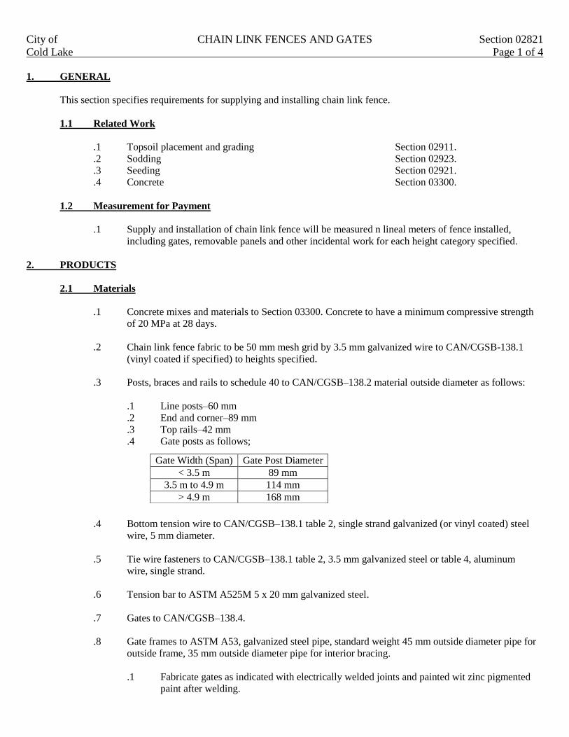
City of CHAIN LINK FENCES AND GATES Section 02821
Cold Lake Page 1 of 4
1. GENERAL
This section specifies requirements for supplying and installing chain link fence.
1.1 Related Work
.1 Topsoil placement and grading Section 02911.
.2 Sodding Section 02923.
.3 Seeding Section 02921.
.4 Concrete Section 03300.
1.2 Measurement for Payment
.1 Supply and installation of chain link fence will be measured n lineal meters of fence installed,
including gates, removable panels and other incidental work for each height category specified.
2. PRODUCTS
2.1 Materials
.1 Concrete mixes and materials to Section 03300. Concrete to have a minimum compressive strength
of 20 MPa at 28 days.
.2 Chain link fence fabric to be 50 mm mesh grid by 3.5 mm galvanized wire to CAN/CGSB-138.1
(vinyl coated if specified) to heights specified.
.3 Posts, braces and rails to schedule 40 to CAN/CGSB–138.2 material outside diameter as follows:
.1 Line posts–60 mm
.2 End and corner–89 mm
.3 Top rails–42 mm
.4 Gate posts as follows;
.4 Bottom tension wire to CAN/CGSB–138.1 table 2, single strand galvanized (or vinyl coated) steel
wire, 5 mm diameter.
.5 Tie wire fasteners to CAN/CGSB–138.1 table 2, 3.5 mm galvanized steel or table 4, aluminum
wire, single strand.
.6 Tension bar to ASTM A525M 5 x 20 mm galvanized steel.
.7 Gates to CAN/CGSB–138.4.
.8 Gate frames to ASTM A53, galvanized steel pipe, standard weight 45 mm outside diameter pipe for
outside frame, 35 mm outside diameter pipe for interior bracing.
.1 Fabricate gates as indicated with electrically welded joints and painted wit zinc pigmented
paint after welding.
Gate Width (Span) Gate Post Diameter
< 3.5 m 89 mm
3.5 m to 4.9 m 114 mm
> 4.9 m 168 mm

City of CHAIN LINK FENCES AND GATES Section 02821
Cold Lake Page 2 of 4
.2 Fasten fence fabric to gate with tie wire fasteners to CAN/CGSB-138.1 table 2, 3.5 mm
galvanized steel or table 4, aluminum wire, single strand.
.3 Furnish gates with galvanized malleable iron hinges, latch and latch catch (provision for
padlock to be specified in contract) which can be attached and operated from either side of
installed gate.
.4 Furnish double gates with chain hook to hold gates open and centre rest with drop bolt for
closed position.
.9 Fittings and hardware to tie wire fasteners to CAN/CGSB-138.2, cast aluminum alloy, galvanized
steel or malleable or ductile cast iron. Tension bar band 3 x 20 mm minimum galvanized steel or 5 x
20 mm minimum aluminum. Post caps to provide waterproof fit, to fasten securely over posts and to
carry top rail. Overhang tops to provide waterproof fit and hold top rails and outward or inward
projections with clips or recesses to hold three strands of barbwire spaced 100 mm apart. Projection
arm to be approximately 300 mm long and project from the fence at 45º above horizontal.
Turnbuckles to be drop forged.
.10 Organic zinc rich coating to CAN/CGSB-1.181.
.11 Barbwire to CAN/CGSB 138.2, 2.5 mm diameter galvanized steel wire to ASTM A121 two (2)
strand with four (4) point barbs at 150 mm spacing.
.12 Grounding rod–16 mm diameter copper well rod, 3 m long.
2.2 Finishes
.1 Galvanizing
.1 For chain link fabric–to CAN-CBSB–138.1.
.2 For pipe 550 g/m² minimum to ASTM A90.
For barbed wire to ASTM A121.
.3 For other fittings to CAN/CSA-G164.
.2 Vinyl coating
.1 .045 mm dry film thickness minimum.
3. EXECUTION
3.1 Grading
.1 Remove debris and correct ground undulations along fence line to obtain smooth uniform gradient
between posts. Provide clearance between bottom of fence and ground surface of 30 mm to 50 mm.
3.2 Erection of Fence
.1 Erect fence along lines as indicated on drawing or as directed by the Engineer and in accordance with
CAN/CGSB–138.3.
.2 Excavate post holes to dimensions shown on the drawing.
.3 Space line posts 3 m apart, measured parallel to ground surface.

City of CHAIN LINK FENCES AND GATES Section 02821
Cold Lake Page 3 of 4
.4 Space straining posts at equal intervals, not exceeding 150 m if distance between end or corner posts
on straight continuous lengths, over reasonably smooth grade is greater than 150 m.
.5 Install additional straining posts as sharp changes in grade and where directed by the Engineer.
.6 Install corner posts where change in alignment exceeds 10 degrees.
.7 Install end posts at end of fence and at buildings. Install gatepost on both sides of gate openings.
.8 Place concrete in postholes, embed posts into concrete to depths indicated on the drawings. Extend
concrete 50 mm above final grade and slope to drain away from posts. Brace to hold posts in plumb
position and true to alignment and elevation until concrete has set.
.9 Do not install fences fabric until concrete has cured a minimum or five (5) days.
.10 Install brace between end and gateposts and nearest line post parallel to ground surface. Install
braces on both sides of corner and straining posts in similar manner. Brace rails to be attached using
brace bands and rail ends. No brace rails are required where fabric height is 1.8m or less.
.
.11 Install caps and overhang tops. Overhang tops to face outwards.
.12 Install top rail between posts and fasten securely to posts with brace bands and rail ends. Secure
waterproof caps and overhang tops.
.13 Install bottom tension wire, stretch tightly and fasten securely to end, corner, gate and straining posts
with turnbuckles and tension bar bands.
.14 Lay out fence fabric. Stretch tightly to tension recommended by manufacturer and fasten to end,
corner, gate and straining posts with tension bar secured to post with tension bar bands spaced at 300
mm intervals. Knuckled tie wire at bottom. Twisted tie wire at top.
.15 Secure fabric to top rails, line posts and bottom tension wire with tie wires at 450 mm intervals.
Give tie wires minimum two (2) twists.
.16 Installation of grounding rods as indicated.
3.3 Installation of Gates
.1 Install gates in locations as indicated.
.2 Level ground between gate posts and set gate bottom approximately 40 mm above ground surface.
.3 Install gate rests where indicated. Determine position of center gate rest for double gate. Cast gate
rest in concrete. Finish concrete flush with ground surface.
.4 Install gate stops where indicated.
3.4 Touch Up
.1 Clean damaged surfaces with wire brush removing loose and cracked coatings. Apply two (2) coats
of organic zinc rich paint to damaged areas. Pre-treat damaged surfaces according to manufacturer
instructions for zinc rich paint.
City of CHAIN LINK FENCES AND GATES Section 02821
Cold Lake Page 4 of 4
3.5 Site Cleanup
.1 Clean and trim areas disturbed by operations. Dispose of surplus material.
.2 Place topsoil as required to provide smooth surface for seeding or sodding and to fill depression
under bottom fence fabric grade line.
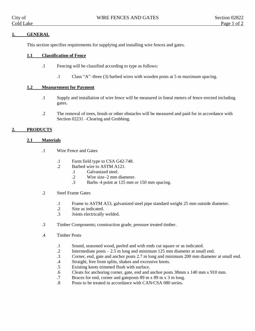
City of WIRE FENCES AND GATES Section 02822
Cold Lake Page 1 of 2
1. GENERAL
This section specifies requirements for supplying and installing wire fences and gates.
1.1 Classification of Fence
.1 Fencing will be classified according to type as follows:
.1 Class “A”–three (3) barbed wires with wooden posts at 5 m maximum spacing.
1.2 Measurement for Payment
.1 Supply and installation of wire fence will be measured in lineal meters of fence erected including
gates.
.2 The removal of trees, brush or other obstacles will be measured and paid for in accordance with
Section 02231 –Clearing and Grubbing.
2. PRODUCTS
2.1 Materials
.1 Wire Fence and Gates
.1 Farm field type to CSA G42-748.
.2 Barbed wire to ASTM A121.
.1 Galvanized steel.
.2 Wire size–2 mm diameter.
.3 Barbs–4 point at 125 mm or 150 mm spacing.
.2 Steel Frame Gates
.1 Frame to ASTM A53, galvanized steel pipe standard weight 25 mm outside diameter.
.2 Size as indicated.
.3 Joints electrically welded.
.3 Timber Components; construction grade, pressure treated timber.
.4 Timber Posts
.1 Sound, seasoned wood, peeled and with ends cut square or as indicated.
.2 Intermediate posts – 2.5 m long and minimum 125 mm diameter at small end.
.3 Corner, end, gate and anchor posts 2.7 m long and minimum 200 mm diameter at small end.
.4 Straight, free from splits, shakes and excessive knots.
.5 Existing knots trimmed flush with surface.
.6 Cleats for anchoring corner, gate, end and anchor posts 38mm x 140 mm x 910 mm.
.7 Braces for end, corner and gateposts 89 m x 89 m x 3 m long.
.8 Posts to be treated in accordance with CAN/CSA 080 series.

City of WIRE FENCES AND GATES Section 02822
Cold Lake Page 2 of 2
3. EXECUTION
3.1 Grading
.1 Level ground along fence line in order that bottom wire of fence between posts can be maintained at
not more than 300 mm above ground.
3.2 Erection of Fence
.1 Erect fences along lines as indicated on drawing or as directed by the Engineer.
.2 Installation of Posts:
.1 Space intermediate posts at 5 m.
.2 Space corner, end and gateposts 3 m from adjacent post.
.3 Locate and erect gateposts as indicated.
.4 Install posts true to line and plumb with 1.5m of post projecting above ground.
.3 Fencing with Wood Posts:
.1 Excavate post holes by methods approved by the Engineer.
.2 Slant of post tops to be perpendicular to fence line and facing inward.
.3 Install cleats for anchoring at corner, date, end and anchor posts as required.
.4 Backfill around posts and compact to same density as surrounding ground. Dispose of
surplus material as directed by the Engineer.
.5 Install braces at end, corner and gateposts. Join braces into posts and spike securely.
.6 Erect wires and stretch to have uniform tension. Splice wires as required.
.7 Attach top wires to posts with minimum two (2) staples. Fasten other wires to posts and
cross braces with at least one staple. Staple wires securely at end, anchor and gateposts.
.8 Stretch two (2) strands of barbed wire along tops of posts and double stable on posts.
3.3 Installation of Gates
.1 Install gates in location as indicated on the drawing.
.2 Install steel frame gates to prevent over stress on gateposts when gates are open. Install on level
ground with ground clearance of 150 mm.
.3 For steel frame gates, locate anchor pipe for drop bolt and install pipe flush with surface.
3.4 Touch Up
.1 Clean damaged galvanized surfaces with wire brush removing loose and cracked coatings. Apply
two (2) coats of organic zinc rich coating.
3.5 Site Cleanup
.1 Clean and trim areas disturbed by operations. Dispose of surplus material and repair damaged areas
as directed by the Engineer.

City of POST AND CABLE FENCE Section 02823
Cold Lake Page 1 of 2
1. GENERAL
This section specifies requirements for supplying and installing post and cable fencing.
1.1 Related Work
.1 Cast in place concrete Section 03300.
1.2 Measurement for Payment
.1 Supply and installation of post and cable fence, including posts and necessary hardware, will be
measured in meters of post and cable fence installed and measured from center to center of end posts.
2. PRODUCTS
2.1 Materials
.1 Cable Guide Rail
.1 Wire cable–diameter of 8 mm galvanized wire rope.
.2 Square timber posts to CAN3-056.
.1 Type pressure treated in accordance with CAN/CSA-080 series.
.2 Dimensions–150 mm x 150 mm x 2.0 m long.
.3 Concrete mixes and materials to Section 03300. Concrete to have a minimum compressive strength
of 20 MPa at 28 days.
.4 Aggregate–16 mm crushed gravel
3. EXECUTION
3.1 Installation
.1 Set posts at locations as indicated by the Engineer.
.2 Excavate post holes to depths and diameter as indicated. Compact bottom to provide firm
foundation. Set posts plumb and centered in hole.
.3 Backfill around posts and anchorages using crushed gravel and compact in uniform layers not
exceeding 150 mm compacted thickness.
.4 Cut off tops of posts as indicated.
.5 Treat cut tops with two (2) coats of chromate copper arsenate (green).
.6 Do concrete work in accordance with Section 03300–cast in place concrete. In porous or caving
soil, use forms for placing concrete as directed by the Engineer.
.7 Erect cable and hardware to details as indicated. Tensions cable so that sag between posts does not
exceed 25 mm.

City of POST AND CABLE FENCE Section 02823
Cold Lake Page 2 of 2
.8 Space cable splices a minimum of 15 m apart. Maximum one (1) cable splice between adjacent posts.
3.2 Site Cleanup
.1 Clean and trim areas disturbed by operations. Dispose of surplus material.

City of INTERLOCKING BLOCK REATAINING WALL Section 02833
Cold Lake Page 1 of 2
1. GENERAL
The work covered by this section includes the furnishings of all labor, materials, equipment and incidentals for
construction and installation of modular block retaining walls as shown on the construction drawings.
1.1 Definitions
.1 Concrete modules–pre cast concrete blocks that form the external fascia of a modular block
retaining wall system.
.2 Wall infill soil–soil which is placed directly behind the wall modules.
.3 Retained soil–an insitu soil or a specified soil which is placed behind the wall infill soil.
.4 Foundation soil–the insitu soil beneath the wall structure.
.5 Base material–imported granular base material placed immediately beneath the concrete modules.
.6 Drainage material–a free draining soil with natural soil filtering capability of a free draining soil
encapsulated in a suitable geotextile or a combination of free draining soil and perforated pipe all
wrapped in a geotextile.
1.2 Measurement for Payment
.1 Excavation for retaining wall construction will be measured in cubic meters for insitu cut.
.2 Construction of wall foundation/footing will be measured in lineal meters.
.3 Supply and placement of weeping tile, complete with filter sock, will be measured in lineal meters.
.4 The retaining wall system will be measured as the square meter of wall face installed. The area shall
be determined as the length of wall for each height increment times the vertical height of the wall
measured form the top of the footing to the top of the capping layer. The contract unit price shall
include the cost of all labor, material and equipment to supply and install the wall modules and
supply and placement of the granular backfill material.
.5 Supply and installation of pedestrian railings will be measured in lineal meters.
2. PRODUCTS
2.1 Material Handling and Storage
.1 Contractor shall check all materials delivered to the site to ensure that the correct materials have been
received.
.2 Contractor shall take care to store all materials on site in such a way that no damage occurs to ay of
the materials. Damaged or contaminated materials shall not be incorporated into any part of the
modular retaining wall system.
2.2 Materials
.1 Concrete Modules
.1 Concrete wall system to be as specified on the drawings.
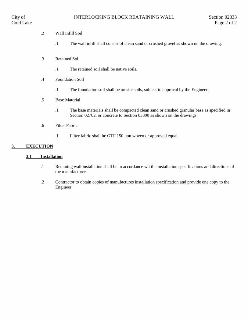
City of INTERLOCKING BLOCK REATAINING WALL Section 02833
Cold Lake Page 2 of 2
.2 Wall Infill Soil
.1 The wall infill shall consist of clean sand or crushed gravel as shown on the drawing.
.3 Retained Soil
.1 The retained soil shall be native soils.
.4 Foundation Soil
.1 The foundation soil shall be on site soils, subject to approval by the Engineer.
.5 Base Material
.1 The base materials shall be compacted clean sand or crushed granular base as specified in
Section 02702, or concrete to Section 03300 as shown on the drawings.
.6 Filter Fabric
.1 Filter fabric shall be GTF 150 non woven or approved equal.
3. EXECUTION
3.1 Installation
.1 Retaining wall installation shall be in accordance wit the installation specifications and directions of
the manufacturer.
.2 Contractor to obtain copies of manufactures installation specification and provide one copy to the
Engineer.

City of STEEL W BEAM GUIDE RAIL Section 02844
Cold Lake Page 1 of 2
1. GENERAL
This section specifies requirement for supplying and installing steel W-beam guide rail for medians and roadsides.
1.1 Measurement for Payment
.1 Supply and erection of roadside steel W-beam guide rail including posts and necessary hardware will
be measured in meters of guide rail installed and measured from outer tip of steel W-beam guide
rail, including guide rail used in anchorages and terminal sections.
.2 Supply and erection of median steel W-beam guide rail including posts and necessary hardware will
be measured in meters of guide rail installed and measured from outer tips of steel W-beam guide
rail, including guide rail used in anchorages and terminal sections.
2. PRODUCTS
2.1 Materials
.1 Steel W-Beam guide rail:
.1 Steel rail and terminal sections to AASHTO M180, Class A (type 1 zinc coated).
.2 Bolts, nuts and washers to ASTM A307, hot dip galvanized to CSA G164.
.3 Organic zinc rich coating to CGSB 1-GP-181M.
.4 Sawn timer post and offset block;
.1 Construction grade lumber, pressure treated in accordance with CAN/CSA 080.0.
.2 Dimensions as indicated.
3. EXECUTION
3.1 Erection
.1 Install posts plumb at locations and to depths as indicated or as directed by Engineer.
.2 Excavate post holes and compact bottom to provide firm foundation. Set post plumb and square in
hole.
.3 Backfill around post using excavated material and compact in uniform layers not exceeding 150 mm
compacted thickness to ground elevation.
.4 Cut off tops of posts as indicated.
.5 Construct anchorages to details as indicated. Place and compact backfill for anchors as direct by
Engineer.
.6 Erect steel W-beam components to details as indicated. Lap joints in direction of traffic. Tighten
nuts to 100 N.m torque. Maximum protrusion of bolt, 6 mm beyond nut.
3.2 Attachment to Concrete Structure
.1 When the terminal point is attached to a concrete structure, install a galvanized C150 x 12 x 7.6 m
long channel below the W-beam guide rail as shown on the drawing.

City of STEEL W BEAM GUIDE RAIL Section 02844
Cold Lake Page 2 of 2
3.3 Painting/Tough up
.1 Galvanized steel touch up:
.1 Clean damaged surfaces with wire brush removing loose and cracked coatings. Apply two
(2) coats of organic zinc rich paint to damaged areas. Pre-treat damaged surfaces according
to manufacturer’s instructions for zinc rich paint.

City of CONCRETE BARRIERS Section 02845
Cold Lake Page 1 of 2
1. GENERAL
This section specifies cast in place or pre-cast New Jersey or similar concrete barriers for medians and roadsides.
1.1 Related Work
.1 Trench excavation, backfill and compaction Section 02315.
.2 Roadway excavation, backfill, subgrade preparation Section 02317.
.3 Granular subbase Section 02721.
.4 Granular base Section 02723.
.5 Concrete formwork Section 03100.
.6 Concrete reinforcement Section 03200.
.7 Cast in place concrete Section 03300.
1.2 Measurement for Payment
.1 Supply and erection of concrete barrier will be measured in meters along its center line.
Measurement will include transition sections at terminals of installation.
2. PRODUCTS
2.1 Materials
.1 External connectors.
.1 Steel as indicated.
.2 Galvanizing to CAN/CSA G164, minimum zinc coating.
.2 Reinforcement to Section 03200 with the following requirements.
.1 Epoxy coated deformed bars, grade as specified by the Engineer.
.2 Wire mesh, grade as specified by the Engineer.
.3 Concrete mix and material to Section 03300.
.4 Granular base to Section 02723.
.5 Curing compound to Section 03300, Type 1-D or Type 2.
.6 Expansion joint filler to ASTM D1751, preformed non extruding resilient bituminous type.
.7 Boiled linseed oil to CAN/CGSB-1.2.
.8 Kerosene to CAN/CGSB-3.3.
3. EXECUTION
3.1 Preparation
.1 Do grading in accordance with Section 02317 and as indicated.
.2 Install granular base in accordance with Section 02723 and as indicated.

City of CONCRETE BARRIERS Section 02845
Cold Lake Page 2 of 2
3.2 Construction
.1 Cast in Place units:
.1 Do forming in accordance with Section 03100.
.2 Install reinforcement in accordance with Section 03200.
.3 Concrete for cast in place units.
.4 Do concrete work in accordance with Section 03300 and as specified herein.
.5 Construct expansion joint in locations and to details as indicated.
.6 Construct contraction joints at 6m spacing by use of compressible insert or by sawing.
.1 Saw cut contraction joint prior to final set and before uncontrolled cracking of
Barrier occurs, as directed by the Engineer.
.7 Round edges, including edges of joints with 10 mm radius edging tool
.8 Finish surface to within 3 mm in 3 m from line, level or grade as measured with a
straightedge placed on surface.
.2 Precast Units:
.1 Do precast concrete work in accordance with Section 03300.
.2 Cast lifting devices into units.
.3 Provide minimum 100 mm cover over reinforcement.
.4 Use only inverted steel forms.
.5 Concrete to be without surface defects to approval of the Engineer finishing will not be
permitted
.6 Storage of precast units on site to be in single layer.
.7 Place concrete barrier units and make connections as indicated. Alignment to be smooth
with no visible deviation.
.3 Boiled linseed oil treatment for cast in place units:
.1 After concrete has cured for specified curing time and when surface of concrete is dry, apply
two (2) coats of linseed oil mixture, consisting of one part linseed oil to one part kerosene,
uniformly to surfaces of guide rails.
.1 First application is 135 ml/m² and second application is 90 ml/m². Allow coatings to
thoroughly dry prior to applying second or subsequent coatings.
.2 Treat all sawn joints with linseed oil mixture.
.3 Do not apply linseed oil mixture to damp surface.
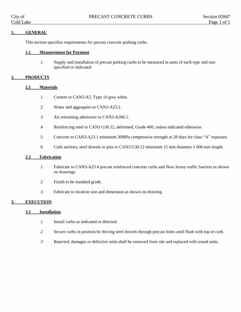
City of PRECAST CONCRETE CURBS Section 02847
Cold Lake Page 1 of 1
1. GENERAL
This section specifies requirements for precast concrete parking curbs.
1.1 Measurement for Payment
.1 Supply and installation of precast parking curbs to be measured in units of each type and size
specified or indicated.
2. PRODUCTS
2.1 Materials
.1 Cement to CAN3-A5, Type 10 grey white.
.2 Water and aggregates to CAN3-A23.1.
.3 Air entraining admixture to CAN3-A266.1.
.4 Reinforcing steel to CAN3 G30.12, deformed, Grade 400, unless indicated otherwise.
.5 Concrete to CAN3-A23.1 minimum 30MPa compressive strength at 28 days for class “A” exposure.
.6 Curb anchors; steel dowels or pins to CAN3 G30.12 minimum 15 mm diameter x 600 mm length.
2.2 Fabrication
.1 Fabricate to CAN3-A23.4 precast reinforced concrete curbs and New Jersey traffic barriers as shown
on drawings.
.2 Finish to be standard grade.
.3 Fabricate to location size and dimension as shown on drawing.
3. EXECUTION
3.1 Installation
.1 Install curbs as indicated or directed.
.2 Secure curbs in position by driving steel dowels through precast holes until flush with top of curb.
.3 Rejected, damages or defective units shall be removed form site and replaced with sound units.

City of TEMPORARY CONSTRUCTION SIGNING Section 02890
Cold Lake Page 1 of 3
1 GENERAL
This section covers the installation, maintenance and removal of temporary signing and traffic control devices which
are specifically related to construction or repair situation and which are generally removed when the work is
complete.
1.1 Related Sections
.1 Traffic control Section 01570.
1.2 Measurement
.1 The supply, installation, maintenance and removal of temporary construction signing or other traffic
control devises including any modification request by the Engineer, will be considered incidental to
the work and will not be paid for separately.
.2 The preparation of traffic accommodations shop drawings and daily recording of temporary
construction signing will also be considered incidental to the work and not paid for separately.
.3 Where traffic accommodation is included as a bid item, payment will be made as described in
Section 01015, Clause 1.5.4.
1.3 Traffic Accommodation Report and Shop Drawings
.1 The Contractor shall prepare a Traffic Accommodation Report stamped and signed by a Professional
Engineer detailing the measures he proposes to use for accommodating traffic throughout the
project. Where revisions of traffic patterns are required due to staging of the Work, separate traffic
control drawings will be required to clearly identify all detour phases. For staged construction,
provide traffic control Drawings numbered consecutively to correspond with identified phase of
construction.
.2 The report shall consist of Drawings detailing the configuration of temporary construction signs and
other traffic control devices in the work zone and written confirmation of the methods and
procedures to be used by the Contractor to address specific traffic safety related issues or situations at
the Work zone.
.3 The Contractor shall submit the Traffic Accommodations Report to the Engineer 14 days prior to the
preconstruction meeting for the project or to a schedule agreed to by the Engineer. The Engineer will
review the report and communicate any concerns to the Contractor within seven (7) days of the
scheduled meeting. Any issues or concerns regarding the contractors proposed report shall be
addressed to the mutual satisfaction of the Contractor and the Engineer prior to the commencement
of the work.
1.4 Public Notices
.1 The Engineer will prepare a detour drawing and will advise The City of the upcoming traffic
restrictions so that the city has adequate time to inform Emergency Services and the Media.

City of TEMPORARY CONSTRUCTION SIGNING Section 02890
Cold Lake Page 2 of 3
2. PRODUCTS
2.1 Materials
.1 The Contractor shall supply all signing materials, including sign posts, weighted stands, brackets any
mounting hardware and other miscellaneous materials required for the erection of temporary
construction signs.
.2 All signs barricades and other traffic control devices shall conform to the requirement for shape,
color and size specified in the Uniform Traffic Control Devices for Canada manual. The orange
portion of all signs shall be fully reflectorized using high brightness, retroreflective, non metalized
prismatic sheeting material that incorporates durable transparent fluorescent pigment.
2.2 Equipment
.1 The Contractor shall supply all equipment required to complete the Work.
3. EXECUTION
3.1 Erection of signs
.1 Work on the project shall not commence until all necessary temporary construction signs and all
other construction signs as proposed in the Traffic Accommodation Report are in place.
.2 When signs require frequent moves, portable type signs mounted on weighted stand may be used.
Portable signs shall be placed on the shoulder of the road such that the face of the sign is fully visible
to oncoming traffic and the bottom of the sign is not less than 0.3 m above the road surface. The
stand shall be securely weighted and erected to ensure against being blown over by prevailing winds
or gusts from passing vehicles.
.3 Non portable signs shall be conspicuously posted and erected at right angles to the roadway with the
bottom of the sign at a height of 1.5 m above the road and not less than 2 m or more than 6 m from
the nearest traffic lane.
.4 Traffic signs and devices shall be moved and kept as close to the work area as practical as
construction proceeds.
.5 Objects within or immediately adjacent to the roadway, which constitute a hazard to traffic shall be
marked with alternating black and orange stripes attached directly to the object or erected
immediately in front of it.
.6 The use of signs shall be kept to a minimum to prevent confusion.
.7 Stop signs shall be installed as directed by the Engineer.
.8 Speed zones where required shall be posted as indicated on the Traffic Accommodation Report
drawings. Signs shall indicate the speed limits as ordered by the Engineer.
3.2 Maintenance and Removal of Signs
.1 Poorly maintained signs, defaced, damaged or dirty construction signs shall be replaced, repaired or
cleaned without delay. Special care must be taken to ensure that construction material and dust are
not allowed to obscure the face of a sign.
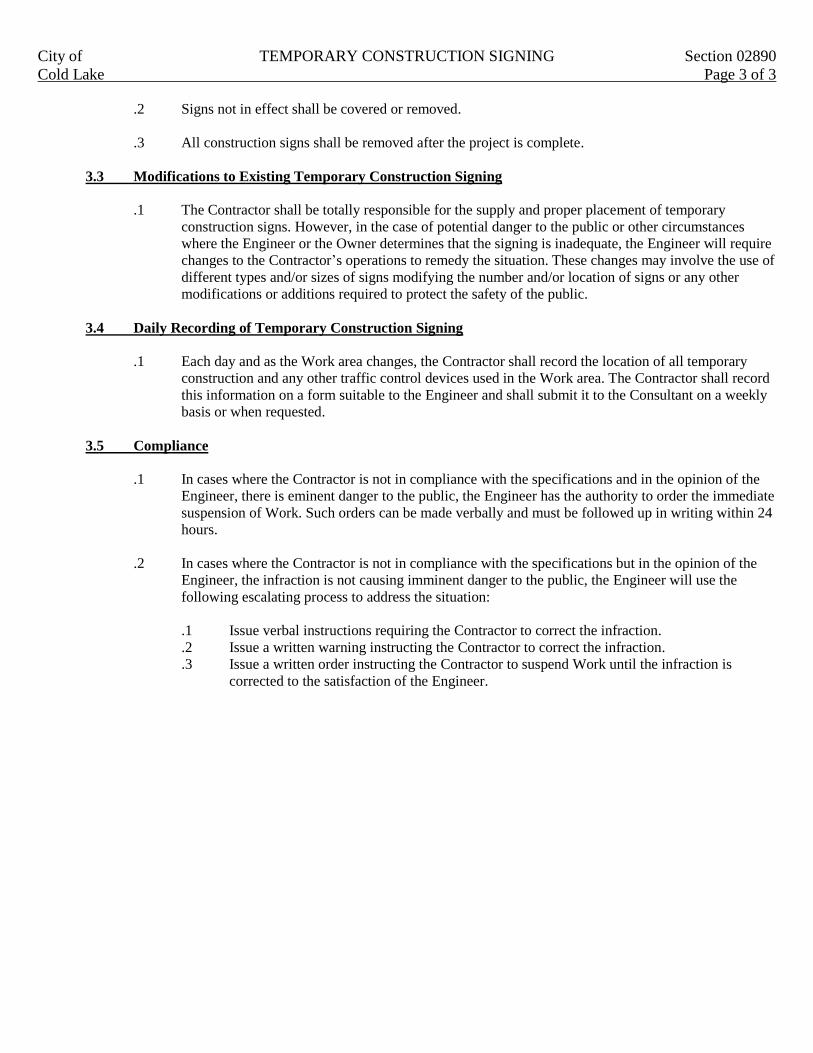
City of TEMPORARY CONSTRUCTION SIGNING Section 02890
Cold Lake Page 3 of 3
.2 Signs not in effect shall be covered or removed.
.3 All construction signs shall be removed after the project is complete.
3.3 Modifications to Existing Temporary Construction Signing
.1 The Contractor shall be totally responsible for the supply and proper placement of temporary
construction signs. However, in the case of potential danger to the public or other circumstances
where the Engineer or the Owner determines that the signing is inadequate, the Engineer will require
changes to the Contractor’s operations to remedy the situation. These changes may involve the use of
different types and/or sizes of signs modifying the number and/or location of signs or any other
modifications or additions required to protect the safety of the public.
3.4 Daily Recording of Temporary Construction Signing
.1 Each day and as the Work area changes, the Contractor shall record the location of all temporary
construction and any other traffic control devices used in the Work area. The Contractor shall record
this information on a form suitable to the Engineer and shall submit it to the Consultant on a weekly
basis or when requested.
3.5 Compliance
.1 In cases where the Contractor is not in compliance with the specifications and in the opinion of the
Engineer, there is eminent danger to the public, the Engineer has the authority to order the immediate
suspension of Work. Such orders can be made verbally and must be followed up in writing within 24
hours.
.2 In cases where the Contractor is not in compliance with the specifications but in the opinion of the
Engineer, the infraction is not causing imminent danger to the public, the Engineer will use the
following escalating process to address the situation:
.1 Issue verbal instructions requiring the Contractor to correct the infraction.
.2 Issue a written warning instructing the Contractor to correct the infraction.
.3 Issue a written order instructing the Contractor to suspend Work until the infraction is
corrected to the satisfaction of the Engineer.
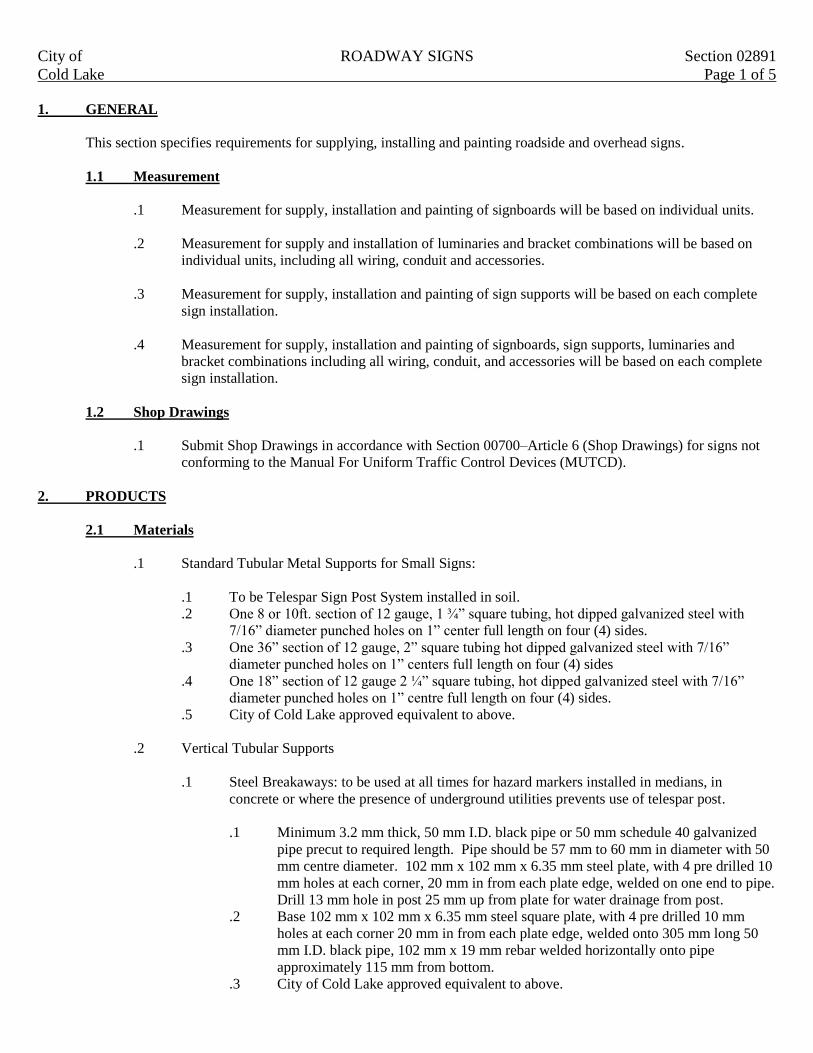
City of ROADWAY SIGNS Section 02891
Cold Lake Page 1 of 5
1. GENERAL
This section specifies requirements for supplying, installing and painting roadside and overhead signs.
1.1 Measurement
.1 Measurement for supply, installation and painting of signboards will be based on individual units.
.2 Measurement for supply and installation of luminaries and bracket combinations will be based on
individual units, including all wiring, conduit and accessories.
.3 Measurement for supply, installation and painting of sign supports will be based on each complete
sign installation.
.4 Measurement for supply, installation and painting of signboards, sign supports, luminaries and
bracket combinations including all wiring, conduit, and accessories will be based on each complete
sign installation.
1.2 Shop Drawings
.1 Submit Shop Drawings in accordance with Section 00700–Article 6 (Shop Drawings) for signs not
conforming to the Manual For Uniform Traffic Control Devices (MUTCD).
2. PRODUCTS
2.1 Materials
.1 Standard Tubular Metal Supports for Small Signs:
.1 To be Telespar Sign Post System installed in soil.
.2 One 8 or 10ft. section of 12 gauge, 1 ¾” square tubing, hot dipped galvanized steel with
7/16” diameter punched holes on 1” center full length on four (4) sides.
.3 One 36” section of 12 gauge, 2” square tubing hot dipped galvanized steel with 7/16”
diameter punched holes on 1” centers full length on four (4) sides
.4 One 18” section of 12 gauge 2 ¼” square tubing, hot dipped galvanized steel with 7/16”
diameter punched holes on 1” centre full length on four (4) sides.
.5 City of Cold Lake approved equivalent to above.
.2 Vertical Tubular Supports
.1 Steel Breakaways: to be used at all times for hazard markers installed in medians, in
concrete or where the presence of underground utilities prevents use of telespar post.
.1 Minimum 3.2 mm thick, 50 mm I.D. black pipe or 50 mm schedule 40 galvanized
pipe precut to required length. Pipe should be 57 mm to 60 mm in diameter with 50
mm centre diameter. 102 mm x 102 mm x 6.35 mm steel plate, with 4 pre drilled 10
mm holes at each corner, 20 mm in from each plate edge, welded on one end to pipe.
Drill 13 mm hole in post 25 mm up from plate for water drainage from post.
.2 Base 102 mm x 102 mm x 6.35 mm steel square plate, with 4 pre drilled 10 mm
holes at each corner 20 mm in from each plate edge, welded onto 305 mm long 50
mm I.D. black pipe, 102 mm x 19 mm rebar welded horizontally onto pipe
approximately 115 mm from bottom.
.3 City of Cold Lake approved equivalent to above.

City of ROADWAY SIGNS Section 02891
Cold Lake Page 2 of 5
.2 Steel Elbows
.1 32 mm black steel pipe, welded 152 mm out and 152 mm down from base of meter.
.2 Cut at 45º angle, weld all around and paint silver in color.
.3 Sign Material
.1 Aluminum Sheet; to ASTM B209M pre-cut to required dimensions with corners rounded to
meet MUTCD standards. Thickness to be 0.081 sign grade aluminum.
.2 Aluminum Extrusion; pre-cut to required dimensions. Extruded aluminum Alcan #6063
T6C street sign blade.
.3 Crezone–¾” medium density overlaid Douglas Fir, premium grade, good one side
.4 Primer for Crezone; Premium Alkyd Exterior Enamel undercoat
.5 Finish Paint: All exterior grade enamel to appropriate color
.4 Fasteners
.1 Bolts, nuts, washers and other hardware for roadside sings to be cast aluminum alloy or
galvanized steel. Stainless gear clamp HS32. Coarse plated ¼”, 1 ¼” NC Grade 5 hexicap
screws for break away posts (concrete base). Street name blade bracket K-6 or K-9 for side
mount, ID-28 for top mount (Alberta Traffic Supply) Bandit strapping materials for 13 mm
bandit strapping.
.5 Silk Screen Ink
.1 Acceptable Material: Ink Ddezyne, GE-103 (Brilliant Red) GE-111 (Black), GE-112
(White), GE-109 (Transparent Red), GE-149 (Transparent Green),GE-159 (Transparent
Blue).
.6 Reflective Sheeting and Tape
.1 To CGSB 69-GP-12C. 3M VIP diamond grade #3990 on all stop and yield signs and 3M
high intensity 3800 series on all other regulatory signs.
.7 Clear Vinyl Protective Coat
.1 3M Scotchcal #3669 Transparent Film
2.2 Fabrication
.1 Crezone Sign Board Blanks
.1 Cut crezone blanks to required shapes and dimensions. Fill edges with wood filler suitable
for outdoor use and sand smooth.
.2 Lightly sand surfaces, wipe clean with DuPont Enamel Reducer thinner or approved equal
and allow to thoroughly dry.

City of ROADWAY SIGNS Section 02891
Cold Lake Page 3 of 5
.3 Paint signboard back and edges with one (1) prime coat and two (2) finish coats in the same
color as the sign face. For non reflective signboard faces spray face with one (1) prime coat
and two (2) finish coats of required color.
.2 Aluminum Sign Blanks
.1 Degrease and etch with chemical conversion coating.
.2 Clean surfaces with DuPont Enamel Reducer or approved equal and allow to thoroughly dry.
.3 Reflective background sheeting and lettering:
.1 Cut and apply in accordance with manufacturers instructions.
.2 Apply adhesive coated material with heat lamp vacuum applicator or by squeeze roll
application method. Apply pressure sensitive material with roller or squeegee.
.3 Match pieces of sheeting from different rolls for each signboard to ensure uniform
appearance and brilliance by day and night.
.4 Reflective signboard faces may be prepared using silkscreen transparent ink.
.5 Non reflective lettering and symbols; cut from vinyl film or paint using required
color of finish paint or silkscreen transparent ink.
.6 Clean signboards completely and apply transparent tape over top edge and extending
25 mm minimum down back and front of signboard.
.7 Protect finished signboard faces with cut lettering with one (1) overlay of transparent
vinyl.
.3 Sign Identification
.1 Mark the back of each sign with Property of City of Cold Lake. Lettering to be ½” high
black letters using outdoor non fading ink covered with 3M-3669 clear vinyl.
3. EXECUTION
3.1 Installation
.1 Sign Support
.1 Erect supports as indicated. Permissible tolerance; 50 mm maximum departure from vertical
for direct buried supports.
.2 Erect posts plumb and square to details as indicated.
.2 Telespar Sign Post System
.1 Attach sleeve and base together flush at the top and drive unit to required depth without
damage leaving 6” of base/sleeve exposed to attach post.
.2 If rock or concrete is encountered, drill hole to required depth and set post in concrete.
.3 Steel Breakaways
.1 Base is placed in concrete with approximately 75 mm to 100 mm maximum of pipe exposed
above ground.
.2 Use four 25 mm x 10 mm steel bolts to attach post to base plate.
.3 ID black pipe posts and bases to be painted silver in downtown core or green outside of
downtown.

City of ROADWAY SIGNS Section 02891
Cold Lake Page 4 of 5
.4 In finished concrete surfaces, backfill with concrete or grout. Protect from adverse
conditions until cured.
.4 Signboard
.1 Fasten signboard to telespar posts with bolts, nuts and washers to steel breakaways with
stainless gear clamp HS32, to light standards with bandit strapping materials.
.2 Use strapping with crimped or bolted connections where signs fastened to light poles (no
fastening allowed to wooden utility poles).
.3 Fasten street markers using the K-6, K-9 or ID-28 (Alberta Traffic Supply) bracket and
aluminum bolts.
3.2 Repair/Restoration
.1 Prepare new message on 0.081 sign grade aluminum sheet.
.2 Replace damages sign with new sign.
3.3 Protection
.1 Place temporary covering on signboards where indicated. Covering to be capable of withstanding
rain, snow and wind and be non injurious to signboard. Replace deteriorated covering and remove
covers as directed by Engineer.
3.4 Correcting Defects
.1 Correct defects identified by Engineer, in sign message, consistency of reflectivity, color or
illumination. Correct angle of signboard and adjust luminaire aiming for optimum performance
during night conditions to approval of Engineer.
3.5 Removal and Salvage
.1 Carefully dismantle and salvage aluminum materials.
.2 Salvage or dispose of existing materials as required in contract.
.3 Contact the Public Works Office (780 639-3776) to confirm delivery time.
.4 Deliver materials to Public Works Yard and unload at designated drop off location.
3.6 Compliance
.1 Regulatory Traffic Control Signs
.1 Regulatory traffic control signs must be completely installed as illustrated on the approved
construction. Drawings and in accordance with MUTCD and City Standards, prior to
eliminating construction zone signage and allowing non construction motor vehicles to travel
on the constructed roadway
.2 Non Regulatory Signs
.1 Non regulatory signs must be installed as per the approved construction drawings and in
accordance with MUTCD and City Standards within two weeks of substantial completion.

City of ROADWAY SIGNS Section 02891
Cold Lake Page 5 of 5
.3 Completion of Sign Installation
.1 Failure to meet the requirements as noted in clauses 3.6.1 and 3.6.2 will result in a penalty of
$500 per day for each calendar day delay in completing this task. The Engineer may extend
the time allowed to complete the sing installation, providing the Contractor submits a written
request to the Engineer.

City of TREE AND SHRUB PRESERVATION Section 02901
Cold Lake Page 1 of 5
1. GENERAL
This section specifies requirements for preserving and protecting trees and shrubs adjacent to excavation.
1.1 Related Work
.1 Clearing and Grubbing Section 02231.
.2 Site Grading Section 02311.
.3 Trench Excavation, Backfill and Compaction Section 02315.
.4 Roadway Excavation, Backfill and Subgrade Preparation Section 02317.
.5 Topsoil Placement and Grading Section 02911.
1.2 Scheduling
.1 Obtain approval from the Engineer of schedule indicating commencement of work.
1.3 Measurement for Payment
.1 No measurement will be made under this Section.
1.4 Notifications
.1 The Contractor shall advise the Recreation, Parks and Facilities Department 48 hours prior to any
work proceeding around trees or shrubs.
2. PRODUCTS
2.1 Materials
.1 Fill: Excavated, pervious soil, from roots, rocks smaller than 75 mm. Excavated material shall be
approved by the Engineer before use as fill.
.2 Coarse washed stones: 35 mm to 75 mm diameter clear round hard stone.
.3 Do not use materials which will affect pH levels of soil.
.4 Drain tile: 100 mm diameter corrugated plastic perforated tubing complete with snap couplings
to CGSB 41-GP-31M.
.5 Peat Moss:
.1 Derived from partially decomposed species of Sphagnum Mosses.
.2 Elastic and homogeneous.
.3 Free of wood and deleterious material which could prohibit growth.
.4 Shredded minimum particle size 5 mm.
.5 pH less than 5.0.
.6 Fertilizer:
.1 To Canada Fertilizer Act and Fertilizer Regulations.
.2 Complete, commercial, slow release 1:5:1 content in water insoluble form.

City of TREE AND SHRUB PRESERVATION Section 02901
Cold Lake Page 2 of 5
.7 Anti desiccant: commercial, wax like emulsion.
.8 Filter Cloth:
.1 Type 1: 100% non woven needle punched polyester, 2.75 mm thick 250 g/m² mass
.2 Type 2: biodegradable burlap.
.9 Wood posts 38 mm x 89 mm x 2,400 mm length untreated wood.
.10 Welded wire fabric (WWF) 100 mm x 100 mm x 3.76 mm to CSA C30.5.
3. EXECUTION
3.1 General
All work shall be done in such a manner as to minimize the effect on trees and shrubs (including root
system). If in the opinion of the Engineer, the Contractor has failed to minimize the effect on trees and
shrubs, the cost of removing repairing and replacing them shall be borne by the Contractor.
3.2 Identification and Protection
.1 Identify plants and limits of root systems to be preserved to satisfaction of Engineer.
.2 Protect plant and root systems from damage, compaction and contamination resulting from
construction to satisfaction of Engineer.
.3 The Engineer is to determine the best method of tree and root protection.
3.3 Root Curtain System
.1 Identify limits for required construction excavation to satisfaction of Engineer.
.2 Maintain minimum distance of 600 mm per 25 mm trunk diameter from trees to edge of excavation
or as approved by the Engineer.
.3 Prior to construction excavation, dig trench minimum 500 mm wide x 1.5 m deep along perimeter of
excavation limits.
.4 Prune exposed roots cleanly at side of trench nearest plants to be preserved. Pruned ends to point
obliquely downwards.
.5 When depth of excavation for wall foundations and footings exceeds 1,500 mm, provide additional
support for posts and curtain as required.
.6 Securely attached Type 2 filter cloth on plant side of wire mesh.
.7 Install wooden posts and welded wire fabric against construction edge of trench.
.8 Prepare homogeneous mixture of fertilizer, parent material and organic matter. Add organic matter
to mixture to achieve 7% to 9% organic matter content by weight. Incorporate with mixture grade
1:5:1 ration dry fertilizer at rate of 1.5 kg/m³.
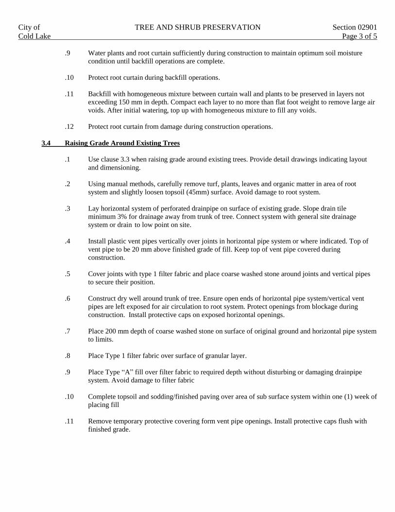
City of TREE AND SHRUB PRESERVATION Section 02901
Cold Lake Page 3 of 5
.9 Water plants and root curtain sufficiently during construction to maintain optimum soil moisture
condition until backfill operations are complete.
.10 Protect root curtain during backfill operations.
.11 Backfill with homogeneous mixture between curtain wall and plants to be preserved in layers not
exceeding 150 mm in depth. Compact each layer to no more than flat foot weight to remove large air
voids. After initial watering, top up with homogeneous mixture to fill any voids.
.12 Protect root curtain from damage during construction operations.
3.4 Raising Grade Around Existing Trees
.1 Use clause 3.3 when raising grade around existing trees. Provide detail drawings indicating layout
and dimensioning.
.2 Using manual methods, carefully remove turf, plants, leaves and organic matter in area of root
system and slightly loosen topsoil (45mm) surface. Avoid damage to root system.
.3 Lay horizontal system of perforated drainpipe on surface of existing grade. Slope drain tile
minimum 3% for drainage away from trunk of tree. Connect system with general site drainage
system or drain to low point on site.
.4 Install plastic vent pipes vertically over joints in horizontal pipe system or where indicated. Top of
vent pipe to be 20 mm above finished grade of fill. Keep top of vent pipe covered during
construction.
.5 Cover joints with type 1 filter fabric and place coarse washed stone around joints and vertical pipes
to secure their position.
.6 Construct dry well around trunk of tree. Ensure open ends of horizontal pipe system/vertical vent
pipes are left exposed for air circulation to root system. Protect openings from blockage during
construction. Install protective caps on exposed horizontal openings.
.7 Place 200 mm depth of coarse washed stone on surface of original ground and horizontal pipe system
to limits.
.8 Place Type 1 filter fabric over surface of granular layer.
.9 Place Type “A” fill over filter fabric to required depth without disturbing or damaging drainpipe
system. Avoid damage to filter fabric
.10 Complete topsoil and sodding/finished paving over area of sub surface system within one (1) week of
placing fill
.11 Remove temporary protective covering form vent pipe openings. Install protective caps flush with
finished grade.
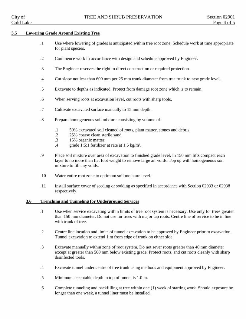
City of TREE AND SHRUB PRESERVATION Section 02901
Cold Lake Page 4 of 5
3.5 Lowering Grade Around Existing Tree
.1 Use where lowering of grades is anticipated within tree root zone. Schedule work at time appropriate
for plant species.
.2 Commence work in accordance with design and schedule approved by Engineer.
.3 The Engineer reserves the right to direct construction or required protection.
.4 Cut slope not less than 600 mm per 25 mm trunk diameter from tree trunk to new grade level.
.5 Excavate to depths as indicated. Protect from damage root zone which is to remain.
.6 When serving roots at excavation level, cut roots with sharp tools.
.7 Cultivate excavated surface manually to 15 mm depth.
.8 Prepare homogeneous soil mixture consisting by volume of:
.1 50% excavated soil cleaned of roots, plant matter, stones and debris.
.2 25% coarse clean sterile sand.
.3 15% organic matter.
.4 grade 1:5:1 fertilizer at rate at 1.5 kg/m³.
.9 Place soil mixture over area of excavation to finished grade level. In 150 mm lifts compact each
layer to no more than flat foot weight to remove large air voids. Top up with homogeneous soil
mixture to fill any voids.
.10 Water entire root zone to optimum soil moisture level.
.11 Install surface cover of seeding or sodding as specified in accordance with Section 02933 or 02938
respectively.
3.6 Trenching and Tunneling for Underground Services
.1 Use when service excavating within limits of tree root system is necessary. Use only for trees greater
than 150 mm diameter. Do not use for trees with major tap roots. Centre line of service to be in line
with trunk of tree.
.2 Centre line location and limits of tunnel excavation to be approved by Engineer prior to excavation.
Tunnel excavation to extend 1 m from edge of trunk on either side.
.3 Excavate manually within zone of root system. Do not sever roots greater than 40 mm diameter
except at greater than 500 mm below existing grade. Protect roots, and cut roots cleanly with sharp
disinfected tools.
.4 Excavate tunnel under centre of tree trunk using methods and equipment approved by Engineer.
.5 Minimum acceptable depth to top of tunnel is 1.0 m.
.6 Complete tunneling and backfilling at tree within one (1) week of starting work. Should exposure be
longer than one week, a tunnel liner must be installed.
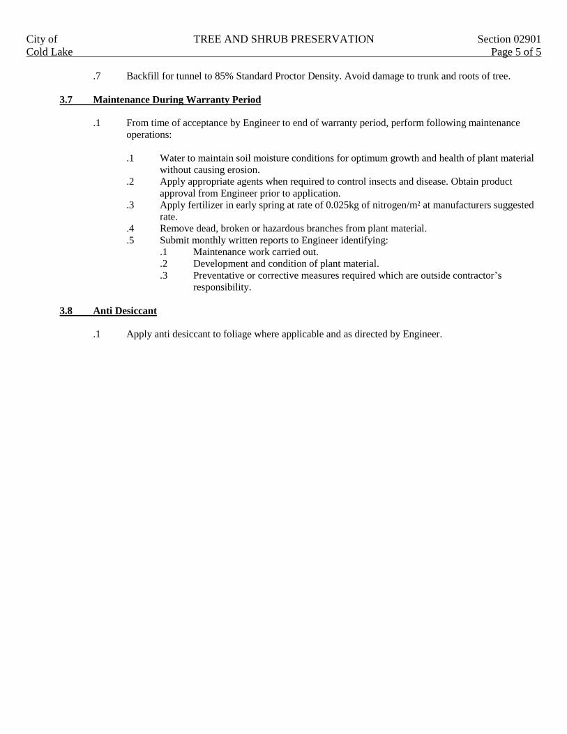
City of TREE AND SHRUB PRESERVATION Section 02901
Cold Lake Page 5 of 5
.7 Backfill for tunnel to 85% Standard Proctor Density. Avoid damage to trunk and roots of tree.
3.7 Maintenance During Warranty Period
.1 From time of acceptance by Engineer to end of warranty period, perform following maintenance
operations:
.1 Water to maintain soil moisture conditions for optimum growth and health of plant material
without causing erosion.
.2 Apply appropriate agents when required to control insects and disease. Obtain product
approval from Engineer prior to application.
.3 Apply fertilizer in early spring at rate of 0.025kg of nitrogen/m² at manufacturers suggested
rate.
.4 Remove dead, broken or hazardous branches from plant material.
.5 Submit monthly written reports to Engineer identifying:
.1 Maintenance work carried out.
.2 Development and condition of plant material.
.3 Preventative or corrective measures required which are outside contractor’s
responsibility.
3.8 Anti Desiccant
.1 Apply anti desiccant to foliage where applicable and as directed by Engineer.

City of PLANTING OF TREES, SHRUBS AND GROUND COVERS Section 02906
Cold Lake Page 1 of 8
1 GENERAL
1.1 Related Work
.1 Site grading Section 02311
.2 Topsoil placement and finish grading Section 02911
1.2 Reference Standards
.1 Do trees, shrubs and ground cover work in accordance with the Canadian Standards for Nursery
Stock, Current Edition except where specified otherwise.
1.3 Source Quality Control
.1 Obtain approval from the Engineer of plant material at source prior to replacement or planting.
.2 Imported plant material must be accompanied with necessary permits and import licenses. Conform
to Federal and Provincial regulations.
1.4 Scheduling
.1 Obtain approval from the Engineer of schedule, seven (7) days in advance of shipment of plant
material.
.2 Schedule to include:
.1 Date for selection of plant material or representative sample at source by Engineer.
.2 Quantity and type of plant material.
.3 Shipping dates.
.4 Arrival dates on site.
.5 Planting dates.
1.5 Product Data
.1 Provide product data for:
.1 Fertilizer.
.2 Anti desiccant.
.3 Guying assembly including collar, guying rope and anchors.
.4 Mulch.
.5 Root barriers.
1.6 Samples
.1 Provide samples for mulch.
1.7 Delivery, Storage and Protection
.1 Protect plant material from frost, excessive heat, wind and sun during delivery.
.2 Immediately store and protect plant material which will not be installed within one (1) day after
arrival at site in storage location approved by Engineer.
.3 Protect plant material from damage during transportation.
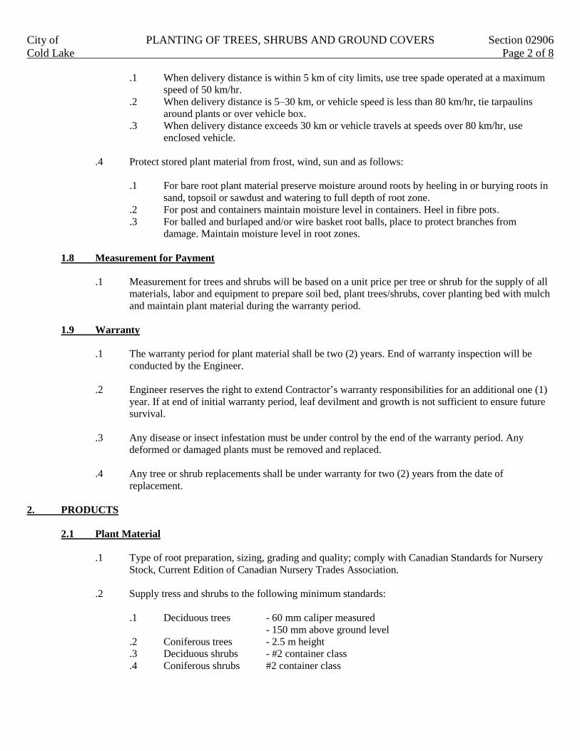
City of PLANTING OF TREES, SHRUBS AND GROUND COVERS Section 02906
Cold Lake Page 2 of 8
.1 When delivery distance is within 5 km of city limits, use tree spade operated at a maximum
speed of 50 km/hr.
.2 When delivery distance is 5–30 km, or vehicle speed is less than 80 km/hr, tie tarpaulins
around plants or over vehicle box.
.3 When delivery distance exceeds 30 km or vehicle travels at speeds over 80 km/hr, use
enclosed vehicle.
.4 Protect stored plant material from frost, wind, sun and as follows:
.1 For bare root plant material preserve moisture around roots by heeling in or burying roots in
sand, topsoil or sawdust and watering to full depth of root zone.
.2 For post and containers maintain moisture level in containers. Heel in fibre pots.
.3 For balled and burlaped and/or wire basket root balls, place to protect branches from
damage. Maintain moisture level in root zones.
1.8 Measurement for Payment
.1 Measurement for trees and shrubs will be based on a unit price per tree or shrub for the supply of all
materials, labor and equipment to prepare soil bed, plant trees/shrubs, cover planting bed with mulch
and maintain plant material during the warranty period.
1.9 Warranty
.1 The warranty period for plant material shall be two (2) years. End of warranty inspection will be
conducted by the Engineer.
.2 Engineer reserves the right to extend Contractor’s warranty responsibilities for an additional one (1)
year. If at end of initial warranty period, leaf devilment and growth is not sufficient to ensure future
survival.
.3 Any disease or insect infestation must be under control by the end of the warranty period. Any
deformed or damaged plants must be removed and replaced.
.4 Any tree or shrub replacements shall be under warranty for two (2) years from the date of
replacement.
2. PRODUCTS
2.1 Plant Material
.1 Type of root preparation, sizing, grading and quality; comply with Canadian Standards for Nursery
Stock, Current Edition of Canadian Nursery Trades Association.
.2 Supply tress and shrubs to the following minimum standards:
.1 Deciduous trees - 60 mm caliper measured
- 150 mm above ground level
.2 Coniferous trees - 2.5 m height
.3 Deciduous shrubs - #2 container class
.4 Coniferous shrubs #2 container class
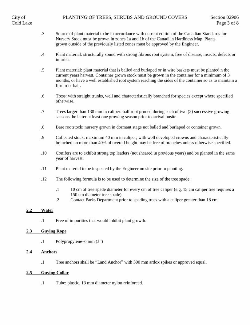
City of PLANTING OF TREES, SHRUBS AND GROUND COVERS Section 02906
Cold Lake Page 3 of 8
.3 Source of plant material to be in accordance with current edition of the Canadian Standards for
Nursery Stock must be grown in zones 1a and 1b of the Canadian Hardiness Map. Plants
grown outside of the previously listed zones must be approved by the Engineer.
.4 Plant material: structurally sound with strong fibrous root system, free of disease, insects, defects or
injuries.
.5 Plant material: plant material that is balled and burlaped or in wire baskets must be planted n the
current years harvest. Container grown stock must be grown in the container for a minimum of 3
months, or have a well established root system reaching the sides of the container so as to maintain a
firm root ball.
.6 Tress: with straight trunks, well and characteristically branched for species except where specified
otherwise.
.7 Trees larger than 130 mm in caliper: half root pruned during each of two (2) successive growing
seasons the latter at least one growing season prior to arrival onsite.
.8 Bare rootstock: nursery grown in dormant stage not balled and burlaped or container grown.
.9 Collected stock: maximum 40 mm in caliper, with well developed crowns and characteristically
branched no more than 40% of overall height may be free of branches unless otherwise specified.
.10 Conifers are to exhibit strong top leaders (not sheared in previous years) and be planted in the same
year of harvest.
.11 Plant material to be inspected by the Engineer on site prior to planting.
.12 The following formula is to be used to determine the size of the tree spade:
.1 10 cm of tree spade diameter for every cm of tree caliper (e.g. 15 cm caliper tree requires a
150 cm diameter tree spade)
.2 Contact Parks Department prior to spading trees with a caliper greater than 18 cm.
2.2 Water
.1 Free of impurities that would inhibit plant growth.
2.3 Guying Rope
.1 Polypropylene–6 mm (3”)
2.4 Anchors
.1 Tree anchors shall be “Land Anchor” with 300 mm ardox spikes or approved equal.
2.5 Guying Collar
.1 Tube: plastic, 13 mm diameter nylon reinforced.

City of PLANTING OF TREES, SHRUBS AND GROUND COVERS Section 02906
Cold Lake Page 4 of 8
2.6 Trunk Protection
.1 Wire mesh: galvanized, electrically welded 1.4 mm wire with 25 mm x 25 mm mesh and fastener.
.2 Plastic: perforated spiraled strip or tubex.
2.7 Mulch
.1 Bark chip: varying in size from 25 mm to 100 mm in diameter, consisting of a mixture of coniferous
and deciduous material.
.2 Wood chips: varying in size from 50 mm to 100 mm and 5 mm to 20 mm thick.
.3 Shredded wood: varying in size fro 25 mm to 100 mm in length.
.4 No other mulch types will be permitted.
2.8 Landscape Fabric
.1 The installation of landscape fabric is not permitted.
2.9 Fertilizer
.1 Synthetic commercial type, ration 2:5:2.
2.10 Anti desiccant
.1 Wax like emulsion.
2.11 Flagging Tape
.1 Fluorescent yellow color.
2.12 Precast Concrete Tree Vaults
.1 As detailed in Division 20–Specification Drawings.
3. EXECUTION
3.1 Preplanting Operations
.1 Verify all underground utility locations.
.2 Ensure plant material acceptable to Engineer.
3.2 Excavation and Preparation for Planting
.1 Preparation of planting soil is specified in Section 02911.
.2 Stake out locations of planting holes and obtain approval from Engineer prior to excavating.

City of PLANTING OF TREES, SHRUBS AND GROUND COVERS Section 02906
Cold Lake Page 5 of 8
.3 Prepare planting hole as follows:
.1 Depth of hole to be equal to height of root ball. Minimum depth of hole to be 400 mm.
.2 Hole width to be twice the root ball diameter.
.4 Remove subsoil rocks roots debris and toxic material from excavated material that will be used as
planting soil for trees and individual shrubs. Dispose of excess material.
.5 Remove water which enters excavation prior to planting. Notify Engineer if water source is
groundwater.
3.3 Planting
.1 Hedge plants shall be space 1.0m apart.
.2 Place plant in centre of hole and adjust height until original growing level matches surrounding
ground level. Use topsoil to adjust height in hole. Lift plant by root ball only.
.3 Remove root ball support material as follows:
.1 Wire baskets and burlap container.
.1 Remove bottom rings before placing tree in hole.
.2 Place tree at proper height and remove top two (2) rings.
.3 Remove accessible burlap.
.2 Fibre pots.
.1 Place in hole to proper height.
.2 Remove entire pot.
.3 Bare root ball preparation.
.1 Remove all damaged tissue taking care not to damage the remaining root material
and leaving a clean cut surface.
.2 Place in hole on firm base to proper elevation.
.4 Tree spade
.1 Prepare planting area as specified in Section 02911.
.2 Remove soil plug using same tree spade used to relocate tree.
.3 Place tree to grade.
3.4 Site Work After Planting
.1 Backfill any voids between spaded plug and the native soil with topsoil in 150 mm lifts. Soil to be
hand tamped only.
.2 Construct 100 mm to 150 mm high water reservoir berm using topsoil at the outside edge of prepared
root zone.
3.5 Watering
.1 Add water to reservoir within two (2) hours of plants being installed. Minimum amount; 70 litres of
water per 25 mm of trunk DBH (diameter at breast height). Water weekly for the first month after
planting, then water a minimum of 12 times per year during the warranty period. Additional water
may be required when recommended by the Engineer.
.2 Refill voids with topsoil to re establish grade.
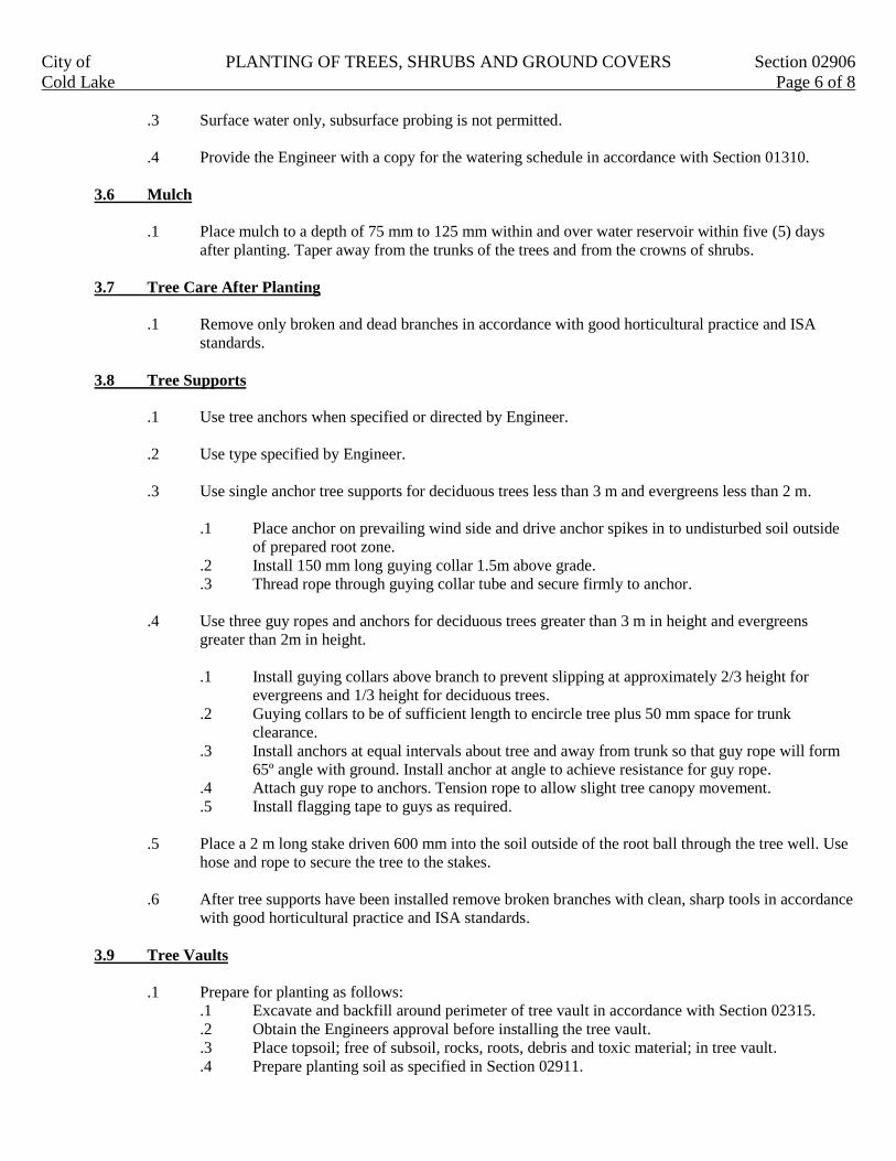
City of PLANTING OF TREES, SHRUBS AND GROUND COVERS Section 02906
Cold Lake Page 6 of 8
.3 Surface water only, subsurface probing is not permitted.
.4 Provide the Engineer with a copy for the watering schedule in accordance with Section 01310.
3.6 Mulch
.1 Place mulch to a depth of 75 mm to 125 mm within and over water reservoir within five (5) days
after planting. Taper away from the trunks of the trees and from the crowns of shrubs.
3.7 Tree Care After Planting
.1 Remove only broken and dead branches in accordance with good horticultural practice and ISA
standards.
3.8 Tree Supports
.1 Use tree anchors when specified or directed by Engineer.
.2 Use type specified by Engineer.
.3 Use single anchor tree supports for deciduous trees less than 3 m and evergreens less than 2 m.
.1 Place anchor on prevailing wind side and drive anchor spikes in to undisturbed soil outside
of prepared root zone.
.2 Install 150 mm long guying collar 1.5m above grade.
.3 Thread rope through guying collar tube and secure firmly to anchor.
.4 Use three guy ropes and anchors for deciduous trees greater than 3 m in height and evergreens
greater than 2m in height.
.1 Install guying collars above branch to prevent slipping at approximately 2/3 height for
evergreens and 1/3 height for deciduous trees.
.2 Guying collars to be of sufficient length to encircle tree plus 50 mm space for trunk
clearance.
.3 Install anchors at equal intervals about tree and away from trunk so that guy rope will form
65º angle with ground. Install anchor at angle to achieve resistance for guy rope.
.4 Attach guy rope to anchors. Tension rope to allow slight tree canopy movement.
.5 Install flagging tape to guys as required.
.5 Place a 2 m long stake driven 600 mm into the soil outside of the root ball through the tree well. Use
hose and rope to secure the tree to the stakes.
.6 After tree supports have been installed remove broken branches with clean, sharp tools in accordance
with good horticultural practice and ISA standards.
3.9 Tree Vaults
.1 Prepare for planting as follows:
.1 Excavate and backfill around perimeter of tree vault in accordance with Section 02315.
.2 Obtain the Engineers approval before installing the tree vault.
.3 Place topsoil; free of subsoil, rocks, roots, debris and toxic material; in tree vault.
.4 Prepare planting soil as specified in Section 02911.

City of PLANTING OF TREES, SHRUBS AND GROUND COVERS Section 02906
Cold Lake Page 7 of 8
.5 Place the trees deep enough in vault to ensure that the mulch is slightly below the hard
surface to allow for proper watering.
3.10 Maintenance Prior to Construction Completion Certificate
.1 Perform following maintenance operation from time of planting to time of issue of the CCC.
.1 Water to maintain soil moisture conditions for optimum establishment, growth and health of
plant material without causing erosion. Minimum amount; 70 litres of water per 25 mm of
trunk DBH. Water weekly for the first month after planting and then water a minimum of 12
times per year during the warranty period. Water thoroughly in late fall prior to freeze up.
Additional water may be required when recommended by Engineer.
.2 Remove weeds before they set seed on a monthly basis or more frequently if required.
.3 Replace or respread damaged missing or disturbed mulch. Taper away from the trunks of
trees and the crowns of shrubs.
.4 Apply pesticides in accordance with federal, provincial and municipal regulations as and
when required to control insects, fungus and disease. Obtain product approval from Engineer
prior to application.
.5 Remove dead or broken branches form plant material in accordance with good horticultural
practice and ISA standards.
.6 Keep trunk protection and guy ropes in proper repair and adjustment.
.7 Remove and replace dead plants and plants not in healthy growing condition. Make
replacements in same manner as specified for original plantings.
3.11 Acceptance for Issue of Construction Completion Certificate
.1 Plant material will be accepted by Engineer after planting operation is completed provided that plant
material exhibits healthy growing condition and is free from disease, insects and fungal organisms.”
Upon completion of planting, an inspection shall be arranged prior to leaf drop. Application for CCC
is subject to all landscaping being completed within the appropriate development phase and a
verification of the “to date watering schedule” being provided at the time of inspection.
.2 Plant material installed less than 90 days prior to frost will be accepted in following year, after June
30, provided that acceptance conditions are fulfilled.
3.12 Maintenance During Warranty Period
.1 From the issue date of the CCC to end of the two (2) year warranty period, perform following
maintenance operations:
.1 Water to maintain soil moisture conditions for optimum growth and health of plant material
without causing erosion. Water a minimum of 12 times during the growing season.
Additional water may be required when recommended by the Engineer.
.2 Reform damaged watering saucers.
.3 Keep area free of weeds.
.4 Replace or respread damaged, missing or disturbed mulch. Taper away from the trunks of
trees and the crowns of shrubs.
.5 Apply pesticides in accordance with Federal, Provincial and Municipal Regulations and
when required to control insects, fungus and disease, obtain product approval from
Engineer prior to application.
.6 Remove dead, broken or hazardous branches from plant material in accordance with good
horticultural practice and ISA standards.
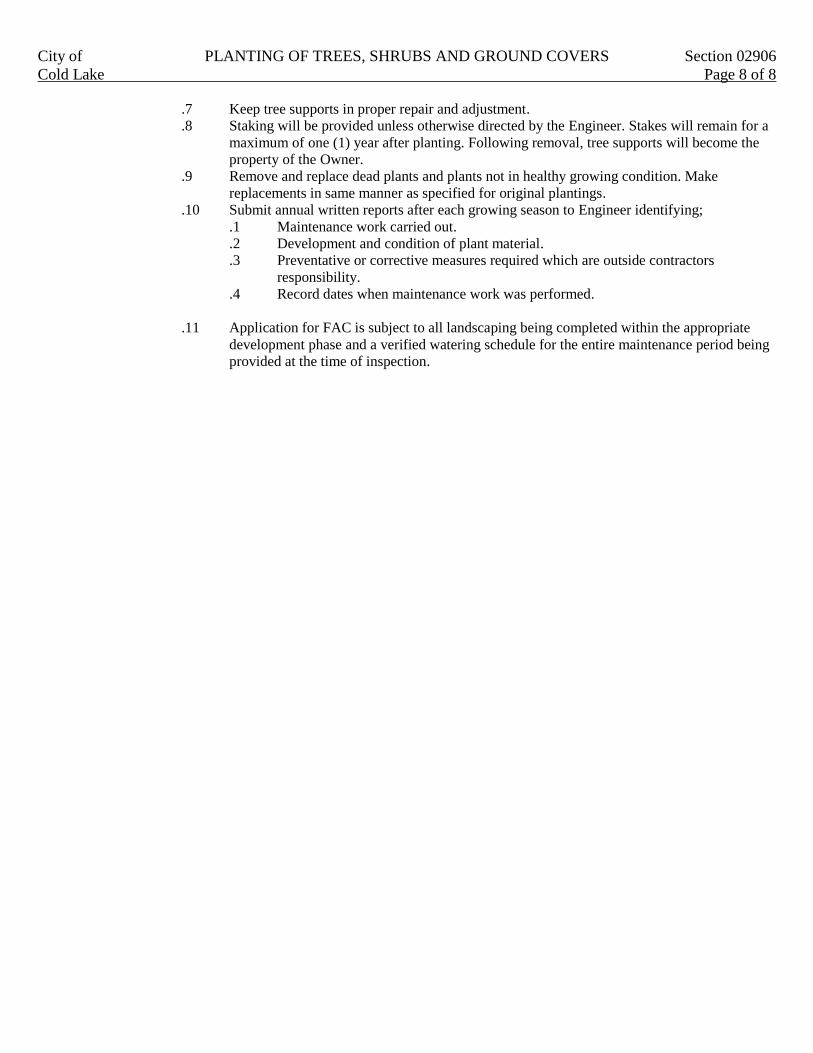
City of PLANTING OF TREES, SHRUBS AND GROUND COVERS Section 02906
Cold Lake Page 8 of 8
.7 Keep tree supports in proper repair and adjustment.
.8 Staking will be provided unless otherwise directed by the Engineer. Stakes will remain for a
maximum of one (1) year after planting. Following removal, tree supports will become the
property of the Owner.
.9 Remove and replace dead plants and plants not in healthy growing condition. Make
replacements in same manner as specified for original plantings.
.10 Submit annual written reports after each growing season to Engineer identifying;
.1 Maintenance work carried out.
.2 Development and condition of plant material.
.3 Preventative or corrective measures required which are outside contractors
responsibility.
.4 Record dates when maintenance work was performed.
.11 Application for FAC is subject to all landscaping being completed within the appropriate
development phase and a verified watering schedule for the entire maintenance period being
provided at the time of inspection.

City of TOPSOIL PLACEMENT AND FINISH GRADING Section 02911
Cold Lake Page 1 of 2
1. GENERAL
This section specifies requirements for final site grading for topsoil placement and covers the supply, placement,
modification and preparation of topsoil.
1.1 Related Work
.1 Site grading Section 02311
.2 Seeding Section 02921
.3 Hydraulic seeding Section 02922
.4 Sodding Section 02923
.5 Preservation of trees and shrubs Section 02901
1.2 Site Conditions
.1 Known underground and surface utility lines and buried objects are indicated on the Drawings.
Contractor to verify locations prior to starting work.
1.3 Protection
.1 Prevent damage to existing trees, roots, fencing, landscaping, natural features, bench marks, existing
buildings, existing pavement, surface or underground utility lines which are to remain. Repair
any damage.
.2 Protect existing trees and shrubs in accordance with Section 02901.
1.4 Samples and Testing
.1 Topsoil must be approved for use in the Work by Engineer.
.2 Supply to the Engineer, four (4) weeks prior to start of topsoil placement a one litre sample and
source of topsoil to be used in the Work.
.3 Subject to the results of soil testing, the Engineer may make recommendations for modifications to
the soil to make it acceptable for use in the Work. Any modifications or additives required will be
considered incidental to the Work.
.4 When source of such topsoil is exhausted topsoil form a new source shall not be until tested and
approved by the Engineer.
1.5 Measurement for Payment
.1 Fine grading will be measured in square meters.
.2 Topsoil placed and prepared from on site sources will be measured in the field for payment by the
square meter.
.3 Imported topsoil placed and prepared will be measured in the field for payment by the square meter.
Free haul to be unlimited.
.4 Herbicide applied according to manufactures recommendations will be considered incidental to the
preparation of the topsoil. There will be no separate payment for herbicide.

City of TOPSOIL PLACEMENT AND FINISH GRADING Section 02911
Cold Lake Page 2 of 2
2. PRODUCTS
2.1 Materials
.1 Topsoil: A fine friable medium loam, capable of sustaining good agricultural growth, meeting
accepted horticultural practices and approved by Engineer. Topsoil shall meet the following
requirements:
.1 Contain a minimum 4% organic matter for clay loams and minimum 2% for sandy loams
.2 Acidity rang pH of 6.0 to 7.8.
.3 Free of subsoil, roots, vegetation, weed seeds, stones larger than 50 mm in greatest
dimension or any other extraneous material.
.4 Topsoil containing noxious weeds is not acceptable.
.2 Herbicide: Round up or other approved chemical base glysophate equal.
3. EXECUTION
3.1 Preparation
.1 Apply herbicide ten (10) days in advance of grading to kill existing weeds and grasses on site if
required by Engineer.
.2 Fine grade subgrade within 50 mm of design rough grade.
.3 Fine grade subgrade eliminating uneven areas and low spots. Remove debris, roots, branches, stones
in excess of 59 mm diameter and building materials. Remove subsoil that has been contaminated
with oil or gasoline.
3.2 Spreading Topsoil
.1 Spread dry topsoil during dry weather over approved dry unfrozen subgrade where indicated.
.2 Bring topsoil up to finished grade.
.3 Apply topsoil to 150 mm minimum depth after settlement.
.4 Manually spread topsoil around existing trees and plants to prevent damage by grading equipment.
.5 Care must be taken to raise existing soil levels within drip line of plant material.
.6 Scarify to a depth of 225 mm to break up lower horizons without substantial mixture of topsoil.
.7 Apply 10-47-0 or equivalent fertilizer at a rate of 450 kg/ha.
.8 Prepare loose friable seed bed by means of rototilling to a depth of 150 mm.
.9 Dispose of debris.
.10 Level surface to final design grades within a tolerance of 25 mm and ensure positive drainage.
.11 Ensure that the topsoil is properly blended into the adjacent property.
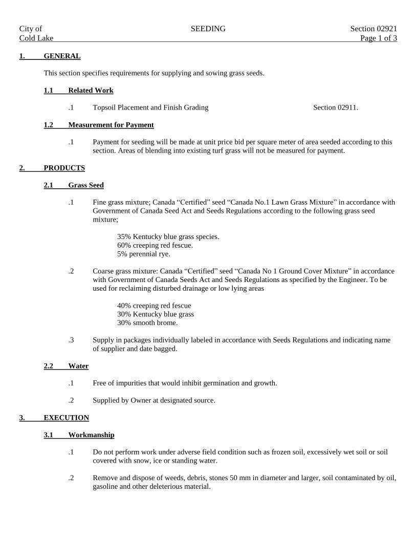
City of SEEDING Section 02921
Cold Lake Page 1 of 3
1. GENERAL
This section specifies requirements for supplying and sowing grass seeds.
1.1 Related Work
.1 Topsoil Placement and Finish Grading Section 02911.
1.2 Measurement for Payment
.1 Payment for seeding will be made at unit price bid per square meter of area seeded according to this
section. Areas of blending into existing turf grass will not be measured for payment.
2. PRODUCTS
2.1 Grass Seed
.1 Fine grass mixture; Canada “Certified” seed “Canada No.1 Lawn Grass Mixture” in accordance with
Government of Canada Seed Act and Seeds Regulations according to the following grass seed
mixture;
35% Kentucky blue grass species.
60% creeping red fescue.
5% perennial rye.
.2 Coarse grass mixture: Canada “Certified” seed “Canada No 1 Ground Cover Mixture” in accordance
with Government of Canada Seeds Act and Seeds Regulations as specified by the Engineer. To be
used for reclaiming disturbed drainage or low lying areas
40% creeping red fescue
30% Kentucky blue grass
30% smooth brome.
.3 Supply in packages individually labeled in accordance with Seeds Regulations and indicating name
of supplier and date bagged.
2.2 Water
.1 Free of impurities that would inhibit germination and growth.
.2 Supplied by Owner at designated source.
3. EXECUTION
3.1 Workmanship
.1 Do not perform work under adverse field condition such as frozen soil, excessively wet soil or soil
covered with snow, ice or standing water.
.2 Remove and dispose of weeds, debris, stones 50 mm in diameter and larger, soil contaminated by oil,
gasoline and other deleterious material.

City of SEEDING Section 02921
Cold Lake Page 2 of 3
3.2 Seed Bed Preparation
.1 Verify that grades are correct. If discrepancies occur, notify engineer and do not commence work
until instructed by Engineer.
.2 Fine grade surface free of humps and hollows to smooth even grade to elevations indicated to
tolerance of plus or minus 25 mm.
.3 Surface drainage is to be as shown on the site grading plan.
3.3 Seed Placement
.1 For mechanical seeding:
.1 Use “Brillion” type mechanical landscape seeder with sand discs which accurately places
seeds at specified depth and rate and rolls in single operation.
.2 Use equipment and method acceptable to Engineer.
.2 For manual seeding:
.1 Use “cyclone” type manually operated seeder.
.2 Rake surface to ensure seed is properly embedded.
.3 Remove any topsoil lumps in excess of 50 mm in size.
.4 Use equipment and method acceptable to Engineer.
.3 On cultivated surfaces, uniformly sow fine grass seed at rate of 170 kg/ha and coarse grass seed at
rate of 75 kg/ha.
.4 Blend applications 150 to 300 mm into adjacent grass areas and previous applications to form
uniform surfaces.
.5 Sow half of required amount of seed in one direction and remainder at right angles.
.6 Embed seed into soil to depth of 6 to 10 mm. Not less than 85% of seed to be placed at specified
depth and covered by soil.
.7 Consolidate mechanically seeded areas by rolling area if soil conditions warrant or if directed by
Engineer, with equipment approved by Engineer immediately after seeding.
.8 Consolidate manually seeded areas by rolling area with equipment approved by Engineer
immediately after seeding.
.9 Protect seeded areas against damage. Remove protection material after lawn areas have been
established and accepted by Engineer.
3.4 Acceptance for Issue of Construction Completion Certificate
.1 Seeded areas will be accepted by Engineer provided that:
.1 Areas are uniformly graded and seeded to Clause 3.1, 3.2 and 3.3 of this Section.
.2 Areas are free of perennial weeds, rocks and debris.

City of SEEDING Section 02921
Cold Lake Page 3 of 3
.2 Deficiencies to be corrected prior to issuance of the Construction Completion Certificate.
3.5 Maintenance During Warranty Period
.1 From the issue date of the CCC to the end of the one (1) year warranty period, perform the following
maintenance operations:
.1 Repair and reseed dead or bare spots, repair rutting and areas of settlement to satisfaction of
Engineer.
.2 Repaired areas must be cut at least three times and seed must be fully established before area
will be accepted.
.3 Cut grass to 50 mm whenever it reaches height of 100 mm.
.4 Eliminate weeds by mechanical means.
3.6 Acceptance for Issue of Final Acceptance Certificate
.1 Seeded areas shall show an average of 85% growth of the seed mix and an absence of perennial
weeds prior to the issue of a Final Acceptance Certificate.
.2 Areas that are deficient in grass catch shall be over seeded with the specified grass seed minus the
5% perennial rye and the warranty period shall be extended for an additional year or until such time
as there is an 85% coverage of the seeded areas with the seeded mix.
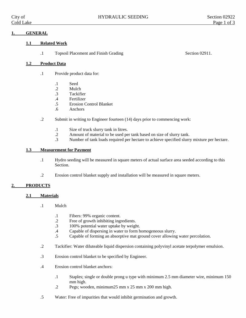
City of HYDRAULIC SEEDING Section 02922
Cold Lake Page 1 of 3
1. GENERAL
1.1 Related Work
.1 Topsoil Placement and Finish Grading Section 02911.
1.2 Product Data
.1 Provide product data for:
.1 Seed
.2 Mulch
.3 Tackifier
.4 Fertilizer
.5 Erosion Control Blanket
.6 Anchors
.2 Submit in writing to Engineer fourteen (14) days prior to commencing work:
.1 Size of truck slurry tank in litres.
.2 Amount of material to be used per tank based on size of slurry tank.
.3 Number of tank loads required per hectare to achieve specified slurry mixture per hectare.
1.3 Measurement for Payment
.1 Hydro seeding will be measured in square meters of actual surface area seeded according to this
Section.
.2 Erosion control blanket supply and installation will be measured in square meters.
2. PRODUCTS
2.1 Materials
.1 Mulch
.1 Fibers: 99% organic content.
.2 Free of growth inhibiting ingredients.
.3 100% potential water uptake by weight.
.4 Capable of dispersing in water to form homogeneous slurry.
.5 Capable of forming an absorptive mat ground cover allowing water percolation.
.2 Tackifier: Water diluteable liquid dispersion containing polyvinyl acetate terpolymer emulsion.
.3 Erosion control blanket to be specified by Engineer.
.4 Erosion control blanket anchors:
.1 Staples; single or double prong u type with minimum 2.5 mm diameter wire, minimum 150
mm high.
.2 Pegs; wooden, minimum25 mm x 25 mm x 200 mm high.
.5 Water: Free of impurities that would inhibit germination and growth.

City of HYDRAULIC SEEDING Section 02922
Cold Lake Page 2 of 3
.6 Fertilizer: Complete synthetic with minimum 65% water soluble nitrogen ratio: 1:4:1 or approved
alternate.
2.2 Grass seed
.1 Fine Grass Mixture: Canada “Certified” seed “Canada No.1 Lawn Grass Mixture” in accordance
with Government of Canada Seeds Act and Seeds Regulations according to the following grass seed
mixture;
. 35% Kentucky blue grass species.
60% creeping red fescue.
5% perennial rye.
.2 Coarse grass mixture: Canada “Certified” seed “Canada No 1 Ground Cover Mixture” in accordance
with Government of Canada Seeds Act and Seeds Regulations as specified by the Engineer. To be
used for reclaiming disturbed drainage or low lying areas
40% creeping red fescue
30% Kentucky blue grass
30% smooth brome.
.3 Supply in packages individually labeled in accordance with seeds regulations and indicating name of
supplier and date bagged.
2.3 Equipment
.1 Truck to be equipped with a minimum 4500 liter slurry tank and pumps capable of maintaining
continuous non fluctuating flow of solution.
3. EXECUTION
3.1 Workmanship
.1 Take reasonable care to prevent spraying items such as structures, signs, guardrails, fences, plant
materials and utilities.
.2 Do not perform work under adverse field conditions such as wind speeds over 20 km/hour, frozen
ground or ground covered with snow, ice or standing water.
3.2 Preparation of Surfaces
.1 Ensure areas to be seeded have been scarified to depth of 300 mm and are moist to depth of 150 mm
before seeding. Fine grade free of humps and hollows and free of deleterious and refuse material.
.2 Obtain Engineers approval of topsoil grade and depth before starting to seed.
3.3 Slurry Application
.1 Slurry mixture applied per hectare;
.1 Seed: 300kg
.2 Mulch: 1600 kg
.3 Tackifier: 50kg
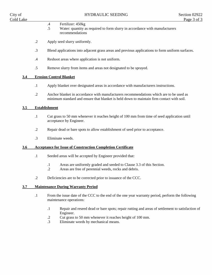
City of HYDRAULIC SEEDING Section 02922
Cold Lake Page 3 of 3 .4 Fertilizer: 450kg
.5 Water: quantity as required to form slurry in accordance with manufacturers
recommendations
.2 Apply seed slurry uniformly.
.3 Blend applications into adjacent grass areas and previous applications to form uniform surfaces.
.4 Reshoot areas where application is not uniform.
.5 Remove slurry from items and areas not designated to be sprayed.
3.4 Erosion Control Blanket
.1 Apply blanket over designated areas in accordance with manufacturers instructions.
.2 Anchor blanket in accordance with manufacturers recommendations which are to be used as
minimum standard and ensure that blanket is held down to maintain firm contact with soil.
3.5 Establishment
.1 Cut grass to 50 mm whenever it reaches height of 100 mm from time of seed application until
acceptance by Engineer.
.2 Repair dead or bare spots to allow establishment of seed prior to acceptance.
.3 Eliminate weeds.
3.6 Acceptance for Issue of Construction Completion Certificate
.1 Seeded areas will be accepted by Engineer provided that:
.1 Areas are uniformly graded and seeded to Clause 3.3 of this Section.
.2 Areas are free of perennial weeds, rocks and debris.
.2 Deficiencies are to be corrected prior to issuance of the CCC.
3.7 Maintenance During Warranty Period
.1 From the issue date of the CCC to the end of the one year warranty period, perform the following
maintenance operations:
.1 Repair and reseed dead or bare spots; repair rutting and areas of settlement to satisfaction of
Engineer.
.2 Cut grass to 50 mm whenever it reaches height of 100 mm.
.3 Eliminate weeds by mechanical means.
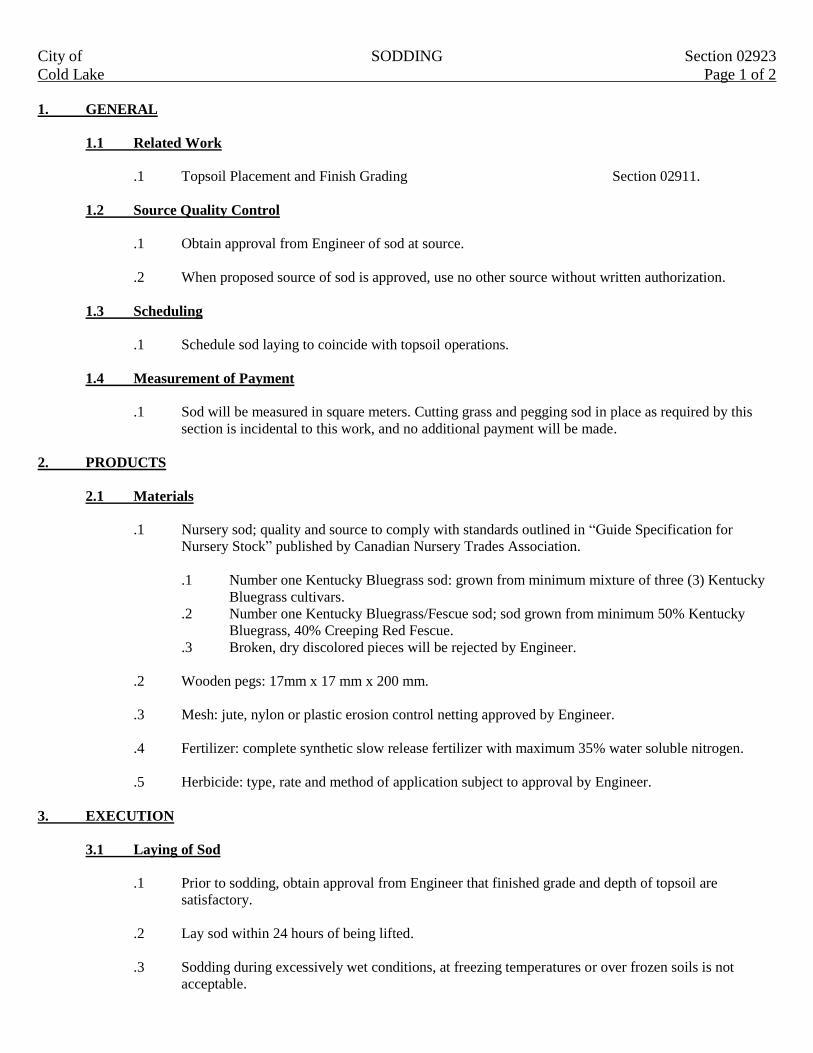
City of SODDING Section 02923
Cold Lake Page 1 of 2
1. GENERAL
1.1 Related Work
.1 Topsoil Placement and Finish Grading Section 02911.
1.2 Source Quality Control
.1 Obtain approval from Engineer of sod at source.
.2 When proposed source of sod is approved, use no other source without written authorization.
1.3 Scheduling
.1 Schedule sod laying to coincide with topsoil operations.
1.4 Measurement of Payment
.1 Sod will be measured in square meters. Cutting grass and pegging sod in place as required by this
section is incidental to this work, and no additional payment will be made.
2. PRODUCTS
2.1 Materials
.1 Nursery sod; quality and source to comply with standards outlined in “Guide Specification for
Nursery Stock” published by Canadian Nursery Trades Association.
.1 Number one Kentucky Bluegrass sod: grown from minimum mixture of three (3) Kentucky
Bluegrass cultivars.
.2 Number one Kentucky Bluegrass/Fescue sod; sod grown from minimum 50% Kentucky
Bluegrass, 40% Creeping Red Fescue.
.3 Broken, dry discolored pieces will be rejected by Engineer.
.2 Wooden pegs: 17mm x 17 mm x 200 mm.
.3 Mesh: jute, nylon or plastic erosion control netting approved by Engineer.
.4 Fertilizer: complete synthetic slow release fertilizer with maximum 35% water soluble nitrogen.
.5 Herbicide: type, rate and method of application subject to approval by Engineer.
3. EXECUTION
3.1 Laying of Sod
.1 Prior to sodding, obtain approval from Engineer that finished grade and depth of topsoil are
satisfactory.
.2 Lay sod within 24 hours of being lifted.
.3 Sodding during excessively wet conditions, at freezing temperatures or over frozen soils is not
acceptable.

City of SODDING Section 02923
Cold Lake Page 2 of 2
.4 Lay sod in rows, perpendicular to slope and with joints staggered. Butt sections closely without
overlapping or leaving gaps between sections. Cut out irregular or thin sections with sharp
implements.
.5 Provide close contact between sod and soil by light rolling. Use of heavy roller to correct
irregularities in grade is not permitted.
.6 Water sod immediately after laying to obtain moisture penetration into top 100 mm of topsoil.
3.2 Laying of Pegged Sod
.1 Place mesh on top of topsoil of slopes as indicated. Secure mesh in place with wooden pegs at
maximum intervals of 1000 mm. Cover mesh lightly with topsoil
.2 Lay sod sections perpendicular to slopes steeper than 3:1 or as indicated and secure with wooden
pegs. Place pegs three per m², 100mm below top edge to prevent shifting of sod and drive pegs flush
with top of sod soil.
3.3 Maintenance Prior to Construction Completion Certificate
.1 Maintain sodded area from start of installation until acceptance.
.2 Water sodded areas in sufficient quantities and at frequency required to maintain soil under sod
continuously moist to depth of 70 to 100 mm.
.3 Cut grass to 50 mm when it reaches height of 100 mm. Remove clippings that will smother grassed
area.
.4 Maintain sodded areas weed free.
3.4 Acceptance for Issue of Construction Completion Certificate (CCC)
.1 Sodded areas will be accepted by Engineer provided that:
.1 Sodded areas are properly established.
.2 Sod is free of bare and dead spots, repair rutting and areas of settlement, and without
perennial weeds.
.3 No surface soil is visible when grass has been cut to height of 50 mm.
.4 Sodded areas have been cut a minimum of two (2) times.
.2 Lawns sodded in fall will be accepted after June 30 provided acceptance conditions are fulfilled.
3.5 Maintenance During Warranty Period
.1 From the issue date of the CCC to the end of one (1) year warranty period, perform the following
maintenance operations:
.1 Repair and resod dead or bare spots, repair rutting and areas of settlement to satisfaction of
Engineer.
.2 Cut grass to 50 mm whenever it reaches height of 100 mm
.3 Eliminate weeds by mechanical means

City of TREE PRUNING Section 02936
Cold Lake Page 1 of 2
1. GENERAL
1.1 Related Work
.1 Prune in accordance with International Society of Arboriculture (ISA) Standards Tree Pruning
Guidelines except where specified otherwise.
1.2 Scheduling
.1 Prior to commencing pruning;
.1 Schedule timing of work with Engineer.
.2 Notify Engineer seven (7) days in advance.
.3 Review extent of work with Engineer of site.
2. PRODUCTS
2.1 Disinfectant
.1 Twenty percent (20%) solution of sodium hypochlorite or 70% solution of ethyl alcohol.
3. EXECUTION
3.1 Sample Pruning
.1 Commence pruning by completing sample pruning operation to demonstrate technique and selection
process used to establish desired form and shape.
3.2 Tool Maintenance
.1 Ensure that tools are clean and sharp throughout pruning operation.
.2 On diseased plant material, disinfect tools with disinfectant before each cut.
3.3 Annual Thinning
.1 Remove dead, dying, diseased, deformed, duplicate and weak growth from plant material as
designated by the Engineer in order to promote healthy growth. Retain natural form and shape of
plant material.
.2 Remove growth designated by Engineer but do not exceed thirty percent (30%) of the trees total
starting volume.
.3 For branches under 150 mm in diameter:
.1 Make cuts smooth and just outside the branch collar. Do not cut lead branches unless
directed by Engineer.

City of TREE PRUNING Section 02936
Cold Lake Page 2 of 2
.4 For branches greater than 150 mm in diameter:
.1 Make first cut on lower side of limb 300 mm from trunk one third diameter of limb.
.2 Make second cut on upper side of limb 500 mm from trunk until limb falls off.
.3 Make final cut adjacent to and outside limb collar.
.5 Ensure that trunk bark and limb collar are not damaged or torn during limb removal.
.6 Remove one of crossed or rubbing branches. Where removal may affect natural form or health of
plant resolve pruning action with Engineer.
.7 Remove exposed portion of girdling root after cleanly cutting root flush with grade on each side of
parent root. Do not injure bark or parent root.
3.4 Timing of Pruning
.1 Prune plant material when plant is in a dormant state or at times designated by Engineer.
3.5 Heading Back
.1 Head back plant material designated by Engineer.
3.6 Coniferous Evergreens
.1 Prune plant material designated by Engineer.
3.7 Hedges
.1 Prune plant material designated by Engineer.
3.8 Care of Wounds
.1 Shape bark around wound to an oblong configuration ensuring minimal increase in would size.
3.9 Clean up
.1 Collect and dispose of pruned material daily and remove from site to location specified by Engineer.
3.10 Report
.1 Report to Engineer condition detrimental to health of plant material.

City of RELINING UNDERGROUND PIPELINES Section 02955
Cold Lake Page 1 of 6
1. GENERAL
This section specifies requirements for supplying the following services, materials and work for the installation of a
cured in place sanitary sewer lining system:
.1 Providing engineering services for the design of the proposed liner system.
.2 Mobilization and demobilization.
.3 Be responsible for traffic control and maintaining access to properties.
.4 Preparation of sewer mains for accepting the liner system. This may include reviewing existing
CCTV tapes, reviewing sanitary sewer service records, reviewing sanitary sewer main and manhole
record drawings, and removal of service connections protruding into the sewer main.
.5 Isolation of sewer during rehabilitation and providing alternate servicing to users.
.6 Supplying and installing cured in place pipe liners.
.7 Re establishing all existing service connections.
.8 Completing final CCTV inspection.
1.1 General Information
.1 This section is specific to cured in place pipe (CIPP) liner installation and is in a generic format. The
CIPP process involves the insertion of a flexible lining into the existing pipe using an inversion
process. The inversion may be accomplished by water, air or a winch.
.2 Contractors proposing CIPP systems and alternatives are required to submit detailed specifications,
methodology, design and construction details A.S.T.M. Standards, and data complying to ASTM
Standards. Relining shall be accomplished by trenchless methods.
1.2 Constraints
.1 The Contractor’s rehabilitation scheme shall not shut off the existing services for more than 16 hours.
Portable toilets shall be provided for the homes affected by the Contractor.
.2 The Contractor shall commit to comply with the work schedule.
.3 The rehabilitation scheme shall be executed without any excavation.
1.3 Measurement for Payment
.1 Cured in place pipe liner to be measured as the length of sewer liner installed, measured horizontally
along the centerline of the sewer from the inside face of manhole to the inside face of manhole. Unit
price bid to be full compensation for the supply of all material, equipment and pant and all work
necessary to the diversion and control of flow from existing sewers and services, installation of the
liner, connection of all existing active service connections, testing. Television inspection after
installations, and all incidental work as necessary and required to complete the work as specified in
the Contract Documents and as directed by the Engineer.

City of RELINING UNDERGROUND PIPELINES Section 02955
Cold Lake Page 2 of 6
.2 Re establishment of service connections to be measured as the number of existing active service
connection re established after installation of the cured in place. Unit price bid shall be full
compensation for all work necessary for the re establishment of existing service connection.
.3 Removal of protruding services to be measured as the number of existing protruding services
removed prior to installation of the cured in place liner. Unit price bid shall be full compensation for
all work necessary for the removal of protruding service connections.
1.4 Scheduling of Work
.1 Provide the Engineer with a schedule detailing each stage of the work.
.2 The work schedule shall be provided a minimum of seven (7) working days in advance of project
commencement. No work shall commence without an approved schedule.
2. PRODUCTS
2.1 Cured in Place Pipes
.1 Supply all materials required to fabricate a CIPP liner to a size that when installed will closely fit the
internal circumference of the conduit to be rehabilitated.
.2 The tube being inverted shall be sized correctly to allow for circumferential stretching during
insertion and ensuring that the existing pipe is completely filled.
.3 The cured in place liner material shall consist of one or more layers of flexible needled fabric or an
equivalent woven and/or non woven fabric. The cured in place liner material shall be capable of
carrying resin, withstanding installation pressures and curing temperature, be compatible with the
resin system used, and be able to cure in the presence or absence of water.
.4 Furnish a cured in place liner material that meets or exceeds the following structural properties:
PROPERTY ASTM TEST INITIAL LONG TERM
Flexural Strength D 790 34 MPa N/A
Flexural Modules D 790 and D 2990 2069 MPa 1034 MPa
.5 The cured in place liner material shall conform to ASTM F1216 using test method D543 and show
chemical resistance to the following types of materials under various concentrations:
CHEMICAL RESISTANCE CONCENTRATION
Sulphuric Acid 20%
Sodium Hydroxide 5%
Ammonium Hydroxide 5%
Nitric Acid 1%
Ferric Chloride 0.1%
Soap 1%
Detergent 0.1%
Bacteriological BOD not less than 700 ppm
The contractor shall furnish data that illustrates the ability of the CIPP liner material to resist chemical attack.
City of RELINING UNDERGROUND PIPELINES Section 02955
Cold Lake Page 3 of 6
3. EXECUTION
3.1 Safety
.1 Operate in strict accordance with Provincial and City Regulations
.2 Observe the Occupational Health and Safety requirements for working with scaffolding and entering
confined spaces and manholes.
.3 Follow the standards and recommended procedures set down in the Alberta Cities Safety Association
Worksite Traffic Accommodation Guidelines for traffic accommodations. Ensure that all field
personnel are familiar with the contents of this manual.
.4 Prior to entering access areas such as manholes and performing inspections of cleaning operations,
an evaluation of the atmosphere to determine the presence of toxic or flammable vapors or lack or
oxygen must be undertaken in accordance with Provincial Statutes.
.5 Observe the requirements for working with chemicals. Provide material safety data sheets (MSDS)
for all chemicals to be used to the city before usage.
3.2 Cleaning of Sewer Line
.1 Remove all internal debris from the sewer line using hydraulically powered high pressure jet cleaners
or mechanically powered equipment.
.2 Where necessary, the City of Cold Lake forces will remove obstacles encountered during the sewer
cleaning operation.
3.3 Inspection of Sewer Line
.1 Review all available CCTV tapes and record drawings.
.2 Obtain additional CCTV inspection data to confirm pipeline condition if available information is not
deemed sufficient.
.3 Perform inspection by personnel trained in locating breaks, obstacles and service connections.
.4 Provide a detailed record of all breaks, severe pipe deformations, significant changes in cross
sections between manholes, obstacles, and service connections. Provide a detailed proposal of how
these issues will be resolved.
.5 Inspect the interior of the sewer line to carefully determine the location of any defects and conditions
which may prevent proper installation of the CIPP into the sewer line.
.6 Be responsible for the survey of the sewer and accuracy of information obtained.
3.4 Bypassing Sewage
.1 Provide for the flow of sewage around the section or sections of pipe designed for CIPP submit
details for approval prior to implementation.
.2 Provide bypassing by plugging the line at an existing upstream manhole and pumping the sewage
flow into a downstream manhole.

City of RELINING UNDERGROUND PIPELINES Section 02955
Cold Lake Page 4 of 6
.3 Provide pumps and bypass lines of adequate capacity and to handle the flow while ensuring no
spillage.
.4 Provide equipment that will conform to applicable noise by laws.
.5 Ensure that no contamination of basements, ditches, roadways, sidewalks, etc. with raw sewage shall
occur. In the event of such contamination, immediate action shall be taken to close the source of
contamination. Proper clean up of the affected area shall be followed and no work shall commence
until a re evaluation of the complete process has been carried out by the public works manager. No
rehabilitation work shall commence unless authorized by the Public Works Director. No extra
payment will be made for decontamination, clean up or down time.
.6 The rehabilitation scheme shall ensure that no upstream flooding occurs during construction. The
Contractor shall allow in his bid prices for monitoring of water levels in manholes and for emergency
pumping.
3.5 Line Obstructions
.1 Advise the Engineer of any lines that require cleaning or removal of obstructions such as solids,
dropped joints, roots, sediments, etc. that will prevent insertion of the CIPP when the work schedule
is delivered. Line obstructions will be removed by the city forces prior to insertion of the CIPP and
no extra payment shall be made for this work.
.2 Be responsible for removing all protruding services that will adversely affect the installation and
integrity of the CIPP.
.3 If an obstruction cannot be removed by sewer clearing method or obstacle removal methods, a pint
repair excavation shall be made by the city forces to uncover and remove or repair the obstruction.
No payment shall be made to the Contractor for these repairs.
.4 Identify such locations during tender time after reviewing the available CCTV tapes and record
plans. No extra payment shall be made for removal of obstructions that were not identified and
reported to the water and wastewater superintendent prior to the commencement of the CIPP
insertion.
3.6 Installation of CIPP
.1 Job Commencement
.1 Prior to commencing work, the Contractor shall submit for the Public Works Director’s or
his designate, approval, his proposal for preparation of liners, transportation, handling,
installing and curing.
.2 Inform affected customers of the length of disruption to service, details of alternate service
provide traffic constraints, nose levels to be expected hours of work and safety concerns.
.2 Processing
.1 Prior to resin impregnation, each liner material shall be inspected for defects.
.2 Allow the city to inspect the materials and resin impregnation process.
.3 Use a resin and catalyst compatible with the CIPP method.
City of RELINING UNDERGROUND PIPELINES Section 02955
Cold Lake Page 5 of 6
.3 Installation
.1 Make minimum lengths adequate to effectively span the distance from the inlet to the outlet
of the respective manholes. Verify lengths in the field.
.2 Make individual inversion runs over one or more manhole sections as determined in the
field, shown on the shop drawings and reviewed by the City of Cold Lake
.3 The polyester saturated lining material shall be inserted through an existing manhole or other
approved access point by means of an inversion process and the application of a hydrostatic
head sufficient to fully extend the lining material to the next designated manhole or
termination point. The procedure used shall produce an identifiable mark at the
service connections.
.4 Lubricants approved by the Engineer can be used to reduce friction during inversion.
.4 Curing and Cool Down
.1 After the inversion placement is completed, supply a suitable heat source and water
distribution or recirculation equipment and perform curing of the resin.
.2 Provide equipment of adequate capacity for delivering hot water throughout the pipe section
to uniformly raise the water temperature above the temperature required to effectively cure
the resin. Temperature shall be maintained during the curing period as recommended by the
resin manufacturer and approved by the City of Cold Lake.
.3 Supply a suitable temperature gauge to monitor the incoming and outgoing water supply
.4 Install another temperature gauge between the impregnated CIPP and the pipe invert at the
remote manhole to determine the temperature during curing.
.5 Maintain curing temperature until the CIPP becomes hard and sound and the remote
temperature sensor indicates that the temperature is of a magnitude to realize an exotherm.
.6 After the CIPP is cured a cool down period shall be used prior to opening the downstream
pipe system, reconnection of services and returning normal flow back to the system.
.7 Cool the hardened CIPP to a suitable temperature before relieving the static head in the
inversion standpipe.
.8 Release the static head to prevent development of a vacuum that could damage the newly
installed CIPP.
.9 Arrange for supply of water required during curing process with the Engineer.
.5 Finish
.1 Ensure that the finished CIPP is continuous over the entire length of an inversion run and be
free from visual defects such as foreign inclusion, dry spots, pinholes, lifts, wrinkles and
delamination. If any of these conditions are present, remove and replace the CIPP in these
areas.
.2 During the warranty period, repair at no cost, any defect which will affect the integrity or
strength of the CIPP to the satisfaction of the City of Cold Lake.
.3 During the warranty period repair at no cost to the City any defects which will affect the
integrity or strength of the liner to the satisfaction of the City of Cold Lake.
3.7 Sealing CIPP at Manholes
.1 If the CIPP fails to make a tight seal at the manhole, apply a seal at that point
.2 Apply a resin mixture seal which is compatible with the CIPP.

City of RELINING UNDERGROUND PIPELINES Section 02955
Cold Lake Page 6 of 6
3.8 Service Connections
.1 After the curing is complete and the pipe system is placed into service, the existing active services
shall be re established.
.2 Reconnection of services shall be done without excavation by means of a remote control cutting
device operating within small diameter pipes or directly where man entry is possible.
.3 A CCTV camera shall be attached to the cutting device for precise location of the service
connections and inspection of the CIPP.
.4 The service connections shall be re established in the same condition as prior to the installation of the
CIPP.
3.9 Clean Up
.1 Upon acceptance of the CIPP, clean up and restore the affected area to the condition that existed
prior to commencement of the work.
.2 Remove and haul debris to an approved disposal site.
3.10 Television and Photographic Inspections of Relined Sewer
.1 Contractor will carry out inspection of rehabilitated sewers by television camera, photographic
camera or by other related means prior to payment for completed work.
.2 Supply to the Engineer one color copy of the digital CCTV recording, together with typed copy of
report. Still photographs 100 mm x 125 mm color showing trouble areas. Identify each section of
sewer on CCTV and cross reference to report. Report to detail significant findings of television
inspection.
.3 At locations where any protruding services have been removed include in the CCTV inspection, a
view of the service lateral from the main showing at least 2 m into the service lead. CCTV
inspection of services from private property to the main sewer may be required if ordered by the
Engineer.
.4 The inspection shall be performed after all mains, manholes and service connections have been
rehabilitated along a section.
.5 Should the video inspection reveal defects in the liner or service connections the Contractor will be
required to repair or replace these defects as ordered by the Engineer at no cost to the City of Cold
Lake.

City of ASPHALTIC CONCRETE PAVEMENT MILLING Section 02961
Cold Lake Page 1 of 2
1. GENERAL
This section specifies requirements for milling or grinding existing asphalt pavement to lines, grades and typical
cross sections indicated on plans or as established by the Engineer.
1.1 Related Work
.1 Pavement Surface Cleaning Section 02966.
.2 Asphaltic Concrete Overlay Paving Section 02786.
1.2 Measurement for Payment
.1 Milling of existing asphalt pavements to be measured in square meters of actual surface area milled
for the area milled in each depth category as specified on unit price table. Depths to be based on the
average of the cute cross sections as measured by Engineer at 20m intervals.
.2 Payment under this item will include operations involved in removing, hauling and stockpiling
designated pavement and cleaning of remaining pavement surface.
1.3 Protection
.1 Protect existing pavement traffic detector loops, home runs, light units, and structures from
damagers. In event of damage immediately replace or make repairs to approval of Engineer and at
no additional cost to owner.
2. PRODUCTS
Not Applicable
3. EXECUTION
3.1 Preparation
.1 Inspect site and verify with Engineer areas designated for milling.
.2 Arrange for temporary traffic control in areas where signal light traffic detector loops and home runs
are to be removed.
.3 No milling will be permitted in excess of five calendar days prior to pavement rehabilitation being
scheduled to be completed. All areas must be clearly marked and signed immediately after milling
work is completed.
3.2 Equipment
.1 Use cold milling or grinding equipment capable of removing part of asphalt pavement surface to
depths or grades indicated with a tolerance of 10 mm within areas designated.
.2 Sweeping and collecting equipment capable of removing all residue from milling operation.
.3 Apply water as necessary during milling operation to suppress dust.

City of ASPHALTIC CONCRETE PAVEMENT MILLING Section 02961
Cold Lake Page 2 of 2
3.3 Asphalt Removal
.1 Mill asphalt pavement to grade and cross section dimensions indicated or directed by Engineer.
.2 Exercise care to avoid disturbance to pavement or other work designated to remain.
.3 Keep drainage system clear of loose and waste materials.
.4 Asphalt is to be removed to a uniform level including areas surrounding valves, manholes or other
appurtenances.
.5 Remove all residue materials resulting from milling operation.
.6 No milling is permitted on arterial roads form 7:00 a.m. to 9:00 a.m. nor 4:00 p.m. to 6:00 p.m. on
weekdays unless permission is granted by Engineer.
.7 Surface to be left in a condition that can be reopened to traffic following removal of grinding.
.8 Milling will include removal of asphalt around manholes and valves at locations determined by the
Engineer. The Contractor is to spray paint exposed manholes and valves fluorescent orange to make
them visible to motorists.
3.4 Disposal of Material
.1 Removed pavement material is property of owner and is to be stockpiled at a location designated by
Engineer.
3.5 Finish Tolerances
.1 Milled surface to be within ± 10 mm of specified grade but not uniformly high or low.

City of HOT IN PLACE ASPHALT RECYCLING Section 02965
Cold Lake Page 1 of 6
1. GENERAL
Hot in place recycling shall consist of heating the existing asphalt concrete pavement, milling the heated pavement,
mixing the milled material, adding as directed fresh aggregate (coated or uncoated), new hot mix asphaltic concrete
pavement, asphalt cement and/or rejuvenating agent and spreading and compacting the resultant mixture all in one
continuous operation to the depths, lines, grades and dimension shown on the plans or designated by the Engineer.
1.1 Related Work
.1 Hot Mix Asphaltic Concrete Paving Section 02741
.2 Pavement Surface Cleaning Section 02966
.3 Painted Pavement Markings Section 02761
.4 Plastic Pavement Markings Section 02762
1.2 Measurement for Payment
.1 Hot in place recycling shall be measured in square meters of surface area completed to the depth
specified.
.2 Rejuvenating agent shall be measured in liters.
.3 Asphalt cement shall be measured in liters.
.4 Hot mix asphaltic concrete shall be measured in tonnes.
.5 Aggregate shall be measured in tonnes.
.6 Pavement surface cleaning shall be considered incidental to the work done under this section.
2. PRODUCTS
2.1 Materials
.1 Asphalt cement: penetration grade 150 – 200 to ASTM D946.
.2 Rejuvenating agent: Witco Chemical Company Cyclogen “L” or approved equal conforming to
ASTM D4552.
.3 Aggregate: the aggregate used in the new hot mix asphalt as an addition without an asphalt cement
coating, or as an addition with an asphalt cement coating, gradation to be specified in the mix design
provided by the Owner.
.4 Hot mix asphalt; new hot mix asphalt used in the work shall conform to Section 02741 and the mix
design specification provided by the Owner.
.5 Recycled hot mix asphalt: the completed hot in place recycled hot mix asphalt shall meet the
requirements of ASTM D3515 and the mix design specification provided by the Owner.

City of HOT IN PLACE ASPHALT RECYCLING Section 02965
Cold Lake Page 2 of 6
2.2 Mix Design
.1 The asphaltic concrete mixture design will be supplied by the Owner. The following information
will be specified in the mix design based on test samples taken from the existing pavement.
.1 Asphalt binder content of the existing asphaltic concrete pavement to be recycled.
.2 Penetration at 25º C and viscosity at 60º C of asphalt cement contained in the asphaltic
concrete pavement to be recycled.
.3 Gradation of the asphaltic concrete pavement to be recycled.
.4 Gradation of new aggregate.
.5 Percent asphalt cement to be added to new aggregate.
.6 Type and amount of rejuvenating agent to be added.
.7 Penetration at 25º c and viscosity at 60º C of asphalt cement in the recycled mixture
(includes asphalt from pavement to be recycled, new asphalt cement and rejuvenating agent).
.8 Aggregate gradation of recycled mixture (includes aggregate in pavement to be recycled and
new aggregate).
.9 Stability and volume analysis information as described in the Asphalt Institute Manual, MS-
2; Mix Design Methods for Asphalt Concrete and Other Hot Mix types.
3. EXECUTION
3.1 Equipment
.1 Heating/milling equipment shall be capable of multi phase heating/milling in which the first unit
heats and mills the pavement to partial depth while the following units heat and mills the remaining
pavement to the total specified depth without charring the asphalt binder. Single phase equipment,
where the total specified depth of pavement is processed (milled and heated) at one point in the
operation will not be permitted.
.2 Distribution and blending units shall be capable of the following:
.1 Positive feed and shut off of the rejuvenating agent.
.2 Control of the quantity of the rejuvenating agent to be metered into the material being
processed at a controlled and uniform rate.
.3 Enable fresh aggregate (coated or uncoated) to be metered into the material being processed
at a controlled and uniform rate.
.4 Enable new hot mix asphaltic concrete pavement to be metered into the material processed at
a controlled and uniform rate.
.5 Uniformly mixing of the recycled pavement, rejuvenating agent, new aggregate (coated or
uncoated) and/or new hot mix asphaltic concrete pavement in a pug mill, continuous mixing
chamber to the requirements of the mix design.
.3 Leveling unit: mechanical paver capable of spreading the mix within the specified tolerances, true to
line, grade and crown indicated.
.4 Compaction: sufficient number of self propelled rollers of type and weight necessary to obtain
specified density of compacted mix.
3.2 Cleaning of Existing Surface
.1 Clean existing surface of all dirt, fabric, rubberized materials, crack sealant, oils, and other
objectionable material in accordance with Section 02966.

City of HOT IN PLACE ASPHALT RECYCLING Section 02965
Cold Lake Page 3 of 6
3.3 Protection
.1 It shall be the responsibility of the Contractor to protect adjacent landscape from damage by
shielding and/or water spray or other methods approved by the Engineer.
3.4 Construction
.1 Heating and Milling/Scarifying
.1 The existing asphalt surface shall be heated a minimum of 100 mm wider on each side than
the width being processed. The processing width shall be as shown on the plans or as
directed by the Engineer. The temperature of the asphalt material prior to milling shall not be
greater than 155º C.
.2 Addition of Rejuvenating Agent
.1 The recycler unit shall be equipped to enable rejuvenating agent to be uniformly added to the
heated and milled mixture. Such equipment shall provide for the following:
.1 Positive feed and shut off interlocked to the movement and processing rate of the
recycler.
.2 Control of the quantity of rejuvenating agent to ± 0.25 l/m² from the application rate
as specified by the mix design.
.3 Measurement of the total volume used by means of a calibrated metering device
capable of recording accumulated litres to an accuracy of ± 2%. Calibration of the
metering device in the presence of the Engineer or by the metering device in the
presence of the Engineer or by some other means acceptable to the Engineer, shall
be done prior to the production of hot in place recycled material.
.4 Heating and maintaining the temperature in a range of 120º C to 155º C. The
temperature established by the Engineer shall not vary by more than ± 5º C form the
target value and shall always be above the lower limit of 120º C.
.2 The Contractor shall uniformly mix the required rejuvenating agent into the mix being
recycled at the rate specified by the mix design.
.3 Addition of Fresh Aggregate
.1 If fresh aggregate (coated or uncoated) is required, as specified in the mix design, then the
Contractor shall provide material meeting the specifications for fresh aggregate (coated or
uncoated). If pre coated aggregate is to be used, then the estimated range of asphalt content
required is from 1% to 3.5% by weight of dry aggregate. The contractor will be responsible
to ensure that the asphalt plant is properly calibrated to produce pre coated aggregate within
this low asphalt content range.
The processed fresh aggregate (coated or uncoated) shall be added to the hot in place
recycling operation at the rate specified in the mix design to form a recycled mixture.
.4 Addition of New Asphaltic Concrete Pavement
.1 If new asphaltic concrete pavement is required, as specified in the mix design, then the
Contractor shall provide material meeting the specifications for new asphaltic concrete
pavement. The new asphaltic concrete pavement shall be added to the hot in place recycling
operation at the rate specified in the mix design to from a recycled mixture.

City of HOT IN PLACE ASPHALT RECYCLING Section 02965
Cold Lake Page 4 of 6
.5 Blending, Mixing, Spreading and Leveling
.1 The recycled pavement materials, rejuvenating agent fresh aggregate, new asphaltic concrete
pavement, shall be fed into a mixing unit and thoroughly mixed. The resulting mixture shall
be fed into a spreading and leveling unit.
.6 Placing
.1 Place asphalt concrete to thicknesses, grades and lines indicated on drawings or directed by
Engineer.
.2 Place asphalt concrete in compacted lifts of 75 mm maximum depth.
.3 Spread and strike off mixture with mechanical finisher.
.4 Construct longitudinal joints and edges parallel to line markings. Lines for paver to follow
parallel to centre line of proposed pavement. Position and operate paver to follow
established line closely.
.5 If segregation occurs, immediately suspend spreading operation until cause is determined
and corrected.
.6 Correct irregularities in surface of pavement course directly behind paver. Remove by shovel
or lute, the excess material forming high spots. Fill and smooth indented areas with hot mix.
Do not broadcast material over such areas.
.7 Do not throw surplus material on freshly screeded surfaces.
.7 Compacting
.1 Roll asphalt continuously to specified density.
.2 Provide a t least one pneumatic tired roller and one steel wheeled roller and as many
additional rollers as necessary to achieve specified pavement density.
.3 Start rolling operations as soon as placed mixture can bear weight of roller without undue
displacement of material or cracking of surface. Initial rolling to be done using a steel
wheeled roller to prevent pick up.
.4 Operate fuller slowly on first pass to avoid displacement of material. For subsequent rolling
do not exceed 5 km/h for steel wheeled rollers and 8 km/h for pneumatic tired rollers.
.5 Overlap successive trips of roller by at least one half width of roller and vary trip lengths.
.6 Keep wheels of roller slightly moistened with water to prevent pick up of material but do not
over water.
.7 After longitudinal joint and edges have been compacted start rolling longitudinally at low
side and progress to high side.
.8 Where rolling causes displacement of material, loosen affected areas at once with lutes or
shovels and restore to original grade of loose material before re rolling.
.9 Do not permit heavy equipment or rollers to stand on finished surface before it has been
compacted and has thoroughly cooled.
.8 Joints
.1 The heating unit shall supply heat a minimum of 100 mm beyond the width of recycling.
When a pass is adjacent to a previously placed mat, the heating shall extend 150 mm into the
adjacent mat and the joint shall be located a minimum of 100 mm into the previously placed
mat.
.9 Finish Tolerances
.1 Finished asphalt surface to be within 5 mm when checked with a 3 mm straight edge placed
in any direction.

City of HOT IN PLACE ASPHALT RECYCLING Section 02965
Cold Lake Page 5 of 6
.10 Surface Irregularities and Defects
.1 Correct irregularities which develop before completion of rolling by loosening surface mix
and removing or adding material as required. If irregularities or defects remain after final
compaction, remove surface course promptly and lay new material to from a true and even
surface and compact immediately to specified density.
.2 Repair areas showing checking or hairline cracking.
.11 Field Quality Testing
.1 A materials testing firm may be hired by Owner to carry out field quality tests as follows:
.1 Aggregate Gradation; one aggregate gradations for each 300 tonnes of production or
at least one per day.
.2 Mix quality: one test of three briquettes for each 300 tonnes of production or at least
one test per day for each of:
.1 Marshall Stability
.2 Specific Gravity
.3 Air Voids and VMA
.4 Flow Index
.5 Asphaltic Content Extraction
.3 Field Density: After asphaltic concrete has been laid and compacted one pavement
core from approximately each 1000 m² of pavement will be obtained at locations
determined by Engineer. Density of core will be measured and compared with the
Marshall Density taken from field samples of the asphalt mix placed in the area of
the core.
.4 If core test results fail to satisfy density requirements as specified, the Contractor
shall immediately modify his construction procedures to produce a uniformly
compacted surface which will satisfy density requirements. Sections with inadequate
compaction shall be subject to a payment reduction as defined under Clause 3.4.13
or rejected as directed by Engineer.
.1 The core test result will be deemed to represent the approximate 1000 m²
area from which it was taken depending on location of other cores taken.
Boundaries of area represented will be determined by Engineer.
.2 If initial core is found to be deficient two additional cores within each
deficient area may be taken by an independent qualified testing firm at
Contractors expense, in locations approved by Engineer. In this case
additional core test results will be averaged with first result to represent area
in question.
.5 Contactor shall give written notice to Engineer 24 hours in advance of any paving
operations to make arrangements for testing.
.6 If test results indicate non compliance with specifications, pavement may be rejected
by Engineer. Pavement thus rejected shall be removed and replaced at Contractor’s
expense.
.7 Cost of additional testing made necessary by Contractor’s unsatisfactory
workmanship or materials will be charged to Contractor.

City of HOT IN PLACE ASPHALT RECYCLING Section 02965
Cold Lake Page 6 of 6
.8 The Contractor shall perform all tests necessary to control the quality of his
materials and workmanship and ensure that his work compiles with the
specifications.
.12 Asphalt Density Tolerances
.1 Hot in place recycled asphalt shall be compacted to minimum density 97% of Marshall
Density.
If asphalt density is found to be deficient according to core tests described under Clause
3.4.12 of this Section, payment of asphaltic concrete surface course within area represented
by core will be reduced. Payment reduction will be equal to unit rate tendered for asphaltic
concrete surface course in question multiplied by payment reduction factor derived from pay
factor curve “B” as listed in Table H appended to Section 02741.
.2 No adjustment to the unit price to be made for areas with a density higher than that specified.
.13 The application of a reduced unit price pursuant to clauses 3.4.12 does not relieve the Contractor of
his contract maintenance requirements.
3.5 Pavement Markings
.1 Painted Pavement Markings to Section 02761.
.2 Plastic Pavement Markings to Section 02762.
.3 The Contractor shall arrange to install temporary pavement markings within two (2) hours following
placement of pavement.
.4 Permanent pavement markings shall be installed within one week following placement of pavement.

City of PAVEMENT SURFACE CLEANING Section 02966
Cold Lake Page 1 of 1
1. GENERAL
This section specifies requirements for cleaning pavement surfaces prior to application of overlay or pavement
marking.
1.1 Related Work
.1 Hot Mix Asphaltic Concrete Paving Section 02741.
.2 Asphaltic Concrete Overlay Paving Section 02786.
.3 Painted Pavement Markings Section 02761.
.4 Plastic Pavement Markings Section 02762.
1.2 Measurement for Payment
.1 Cleaning pavement surfaces to be incidental to work for which required.
2. PRODUCTS
2.1 Materials
.1 Abrasives and solvents used for removal of paint, oil, grease, rubber deposits, etc. to be products
specially designed for pavement cleaning subject to approval of Engineer.
3. EXECUTION
3.1 Pavement Surface Cleaning
.1 Remove to existing pavement level, any material which has protruded excessively and dispose of
removed materials as directed.
.2 Remove by approved methods, dust, contaminants, loose and foreign materials, oil and grease,
ponded water, frost and ice. Deposit in areas designated by Engineer.
.3 Use rotary power brooms or street sweeper supplemented by hand brooming as required.
.4 Protect storm drainage system from dust, loose and waste materials.
.5 Pavement surface prior to application must be dry, clean and above 4 degrees C.
City of ROUTING AND SEALING PAVEMENT CRACKS Section 02982
Cold Lake Page 1 of 2
1. GENERAL
This section specifies requirements for repairing cracks in existing pavements that are not being overlaid within one
year.
1.1 Related Work
.1 Plastic Pavement Markings Section 02762.
1.2 Measurement for Payment
.1 Pavement crack routing and sealing shall be measured in lineal meters. Unit price bid shall be full
compensation for all work involved in routing and sealing cracks.
2. PRODUCTS
2.1 Materials
.1 Hot poured rubberized asphalt to be Beram 195 LM or approved equal.
3. EXECUTION
3.1 Equipment
.1 Router and Cutter Bits
.1 Router shall be flexible and portable as required to follow random cracking.
.2 Router shall have cutter bits that will cut a minimum size groove 20 mm wide and 10 mm
deep.
.2 Compressed air equipment
.1 Compressor shall have a capacity of 2 m³/min or greater at 550 kPa, and be oil and water
free.
.2 Air shall be delivered through a blow pipe with a maximum diameter of 16 mm to ensure an
airstream capable of effectively cleaning out the routed cracks.
.3 Hot air lance as approved by Engineer.
.4 Portable oil jacketed type double boiler melter with a mechanically operated agitator and separate
thermometric controls and gauges for sealant and heat transfer oil shall be used when applying
rubberized asphalt. A tar kettle may be used for catalytic asphalt.
.5 Pouring pots shall have an oblong body no splash top drip tight fingertip control valve and minimum
sized pouring tip to prevent overspray.
3.2 Preparation
.1 A review of surfaces to be crack sealed shall be undertaken with Engineer to establish physical limits
of cracks to be sealed.
.2 All cracks designated by Engineer for sealing shall be routed to a minimum width of 20 mm and a
depth of 10 mm. Router cut shall be perpendicular to the pavement surface.

City of ROUTING AND SEALING PAVEMENT CRACKS Section 02982
Cold Lake Page 2 of 2
.3 Routed cracks must be dry, free from frost, laitance, residual dust and debris. Cracks shall be
cleaned immediately prior to sealing using compressed air equipment and other mechanical means as
required. Cracks shall be completely cleaned to expose freshly routed surfaces.
3.3 Placing of Sealant
.1 Sealant shall be melted in accordance with manufacturers instructions. Diluted overheated or burned
materials shall be removed from work site and suitably disposed of.
.2 Melted sealant shall be placed into routed cracks in accordance with manufacturers instructions.
Sealant shall be placed using a pouring pot or approved pressure wand, then leveled with an
approved squeegee, flush with pavement surface and shall not be more three (3) mm below
pavement surface after cooling.
.3 Crack sealant is to be sprayed with liquid soap or dusted with limestone or flyash immediately after
being placed, to stop traffic from tracking or pulling out sealant.
.4 Sealant spilled on pavement surface shall be removed and area sprinkled lightly with fine sand.
.5 Place sealant when air temperature is above 10º C and daily low temperature does not fall below 5º C
and no rain is forecast.
3.4 Clean Up
.1 Clean all sidewalks of debris blown from routed cracks. Sweep debris onto roadway for removal by
street sweepers.
City of PAVEMENT CRACK CLEANING AND FILLING Section 02983
Cold Lake Page 1 of 2
1. GENERAL
This section specifies requirements for repairing cracks in pavement surfaces prior to surface treatments or
overlays (crown paving).
1.1 Samples
.1 Submit to Engineer at least two (2) weeks prior to commencing work, the following samples of
materials proposed for use;
.1 One 4 L container of asphalt material. Submit emulsions in a plastic container.
.2 One 20 kg sample of each aggregate gradation.
.2 Provide access for Engineer to sample materials actually incorporated into work as required.
1.2 Measurement for Payment
.1 Pavement crack cleaning and filling to be measured and paid for by meter of crack successfully
sealed.
2. PRODUCTS
2.1 Materials
.1 Anionic emulsified asphalt to CAN2-16.2 grade SS-1.
.2 Cutback asphalt to CAN2-16.1 grade RC-250.
.3 Aggregate for crack filling to be clean sand or crushed screenings with a sand equivalent not less
than 45% when tested to ASTM D2419.
.4 Aggregate gradation to be within following limits when tested to ASTM C136 and ASTM C117
(AASHTO T27 and T11).
.1 For sand asphalt slurry using emulsion:
Sieve Size (microns) % Passing
2,500 100
315 25 – 50
200 12.- 30
80 3 – 12
.2 For sand asphalt mix using cutback asphalt:
Sieve Size (microns) % Passing
2,500 100
80 0 – 8
.5 Mixing water; potable

City of PAVEMENT CRACK CLEANING AND FILLING Section 02983
Cold Lake Page 2 of 2
2.2 Mixes
.1 Determine exact proportions for preparing filling mixes by site conditions and subject to approval of
Engineer.
.2 Prepare sand asphalt slurry or mix with approximate following proportion;
.1 50 kg of aggregates
.2 10 to 16L of asphalt
.3 Water to produce uniform slurry of consistency to achieve full penetration into cracks.
3. EXECUTION
3.1 Application Equipment
.1 Pouring pots or approved pressure wand.
3.2 Preparation
.1 Clean cracks designated by Engineer.
.2 Remove by use of hooks or other suitable tools and loose materials from spilled edges, from surface
and to a minimum depth of 50 mm.
.3 Clean loose materials from cracks with compressed air, free of oil and water, applied at pressure not
less than 550 kPa, or by other approved means.
.4 Dispose of materials removed from cracks as directed. Do not contaminate drainage system.
3.3 Crack Filling
.1 Fill cracks exceeding a width of 5 mm.
.2 Fill cracks when air temperature is above 10º C and daily low temperature does not fall below 5º c
and no rain is forecast.
.3 Cracks shall be clean and dry.
.4 Fill and tamp cracks to minimum 50 mm depth and level with pavement surface. Due to shrinkage
of mixture, two (2) or more separate applications may be required for tight sealing.
.5 Remove and dispose of excess filler material as directed.

City of REMOVAL AND REPLACEMENT OF EXISTING CONCRETE WORK Section 02985
Cold Lake Page 1 of 8
1. GENERAL
This section specifies the requirements for the removal and replacement of Portland Cement, concrete and concrete
paving stone work, including;
Monolithic curb, gutter and sidewalk
Separate sidewalk
Curb and gutter
Curb on asphalt base
Paraplegic ramps (Wheelchair / Bike)
Concrete cap medians and traffic islands
Monolithic slab medians and traffic islands on asphalt base
Reinforced lane and driveway crossings
Swales
Combined concrete/paving stone sidewalks
Combined concrete/paving stone lane crossing
Miscellaneous concrete work
1.1 Related Work
.1 Site Work Demolition and Removal Section 02225.
.2 Roadway Excavation, Backfill and Subgrade Preparation Section 02317.
.3 Concrete Curbs, Gutters, Sidewalks, Medians Section 02770.
.4 Concrete Paving Stone Section 02780.
.5 Topsoil Placement and Grading Section 02911.
.6 Sodding Section 02923.
.7 Tree and Shrub Preservation Section 02901.
.8 Concrete Reinforcement Section 03200.
.9 Cast in Place Concrete Section 03300.
.10 Slip Formed Concrete Section 03370.
1.2 Definitions
.1 Hand Formed Concrete Work: means the conventional method of construction using forms.
.2 Extruded Concrete: means construction of concrete work using slip form paving machines.
.3 Sidewalk Flagging: means the removal and replacement of the sidewalk section of a monolithic curb,
gutter and sidewalk cross section by saw cutting along the back of curb surface joint and removing
the sidewalk panel.
.4 Curb Flagging: means the removal and replacement of the curb and gutter of a monolithic curb,
gutter and sidewalk cross section by saw cutting along the back of the curb surface joint and
removing the curb and gutter and installing dowel pins into the sidewalk then replacing the curb and
gutter.

City of REMOVAL AND REPLACEMENT OF EXISTING CONCRETE WORK Section 02985
Cold Lake Page 2 of 8
1.3 Concrete Work Dimensions
The existing concrete work, in particular 1.5 m monolithic curb, gutter and sidewalk may vary in
width from the current cross section by 150 mm plus or minus. The contractor is to construct the
new concrete work to the original dimensions or as directed by the Engineer. No additional payment
will be made for a variance in width of 150 mm or less.
1.4 Measurement for Payment
.1 The Contractor shall submit locations and measurement of work completed on a weekly basis to the
City as an indicator of work progress. Payment will be made based on measurements taken by the
Engineer.
.2 Disposal of concrete work and other items of work to be at locations specified in Section 02225.
.3 The quantities determined as specified in this section will be paid for at the contract unit prices,
which shall be full compensation for furnishing of all materials, labor, tools and incidentals necessary
to complete the work in accordance with the specifications plans and instructions from the Engineer.
.4 The following work will be incidental to the work specified in this Section and no separate payment
will be made.
.1 Saw cutting concrete work and asphaltic concrete pavement.
.2 Removal and disposal of concrete work asphaltic concrete pavement and other waste
materials.
.3 Sub grade preparation.
.4 Supply and placement of 20 mm crushed gravel for hand formed concrete work as shown on
the drawings or as specified.
.5 Repair of roadway adjacent to new concrete work.
.6 Backfill required behind new concrete work.
.7 Tree and shrub preservation.
.8 Placement of plastic sleeves and rebar around standpipes and valve boxes.
.9 Supply and placement of dowel pins.
.10 Removal and replacement of private precast concrete sidewalk blocks.
1.5 Over excavation of unsuitable sub grade and replacement with 20 mm crushed gravel shall be
measured in cubic meters in place.
1.6 Measurement for concrete work shall be as follows:
.1 1.5 m monolithic curb, gutter and sidewalk shall be measured in lineal meters, as measured along the
centre of the sidewalk.
.2 Monolithic curb, gutter and sidewalk over 1.5 m in (± 150 mm) width shall be measured in square
meters. Width to be measured from lip of gutter to back of walk.
.3 Removal of existing 1.2 m (± 100 mm) separate sidewalk and replacement with 1.5 m separate
sidewalk to be measure din lineal meters.
.4 Removal of existing separate sidewalk and replacement of separate sidewalk of the same width (±
150 mm) to be measured in square meters.
.5 Sidewalk flagging including installation of dowel pins to be measured in square meters.
City of REMOVAL AND REPLACEMENT OF EXISTING CONCRETE WORK Section 02985
Cold Lake Page 3 of 8
.6 Curb flagging including installation dowel pins to be measured in lineal meters as measured along
the face of curb.
.7 Separate sidewalk pinned to existing curb and gutter to form a monolithic unit including supply and
placement of dowel pins shall be measured in square meters.
.8 Curb and gutter to be measured in lineal meters as measured along the face of curb.
.9 Curb on asphalt base, including supply and placement of dowel pins and reinforcing steel to be
measured in lineal meters as measured along the face of curb.
.10 Construction of wheel chair/bike ramps shall be considered incidental to the sidewalk construction.
No additional payment will be made for wheel chair/bike ramps.
.11 Concrete caps for medians and islands to be measured in square meters.
.12 Monolithic slab medians and traffic islands to be measured in square meters.
.13 Reinforced lane and driveway crossing shall be measured in square meters. Width to be measured
from lip of gutter to back of walk.
.14 Removal of existing curb, gutter and separate sidewalk and replacement with a reinforced monolithic
driveway or lane crossing shall be measured in square meters. Width to be measured from lip of
gutter to back of walk.
.15 Reinforced curb and gutter lane and driveway crossings to be measured in lineal meters along the
face of curb.
.16 Removal and replacement of private sidewalk to be measured in square meters.
.17 Concrete swales shall be measured in lineal metes along the centre line of the swale for the width
specified.
.18 Extra gravel or approved material will be measured in cubic meters.
1.7 Measurement for concrete paving stone work will be as follows;
.1 New concrete paving stone sidewalks shall be measured in square meters in place. The unit price bid
will be full compensation for saw cutting, removal and disposal of concrete work, sub grade
preparation supply and placement of granular base, supply and placement of edge restraint, supply
and placement of sand leveling course, supply and placement of concrete paving stone and other
incidentals necessary to complete the Work.
.2 Concrete work including curb and gutter required for new paving stone work to be measured in
square meters.
.3 New concrete paving stone lane crossing driveway crossings and crosswalks will be measured in
square meters. The unit price bid will be full compensation for saw cutting removal and disposal of
concrete work sub grade preparation construction of concrete base, supply and placement of leveling
sand supply and placement of concrete paving stone and other incidentals necessary to complete the
Work.

City of REMOVAL AND REPLACEMENT OF EXISTING CONCRETE WORK Section 02985
Cold Lake Page 4 of 8
.4 Repair of existing concrete paving stone work shall be measured in square meters. Unit price bid will
be full compensation for removal and stockpiling of existing paving stones, supply and placement of
sand leveling course replacement of paving stones and other incidentals necessary to complete the
Work.
.5 Repair of existing concrete paving stone lane and driveway crossings will be measured in square
meters. The unit price bid will be full compensation for removal and stockpiling of existing paving
stone, removal and replacement of concrete work, supply and placement of sand leveling course,
replacement of paving stone and other incidentals necessary to complete the Work.
1.8 Adjustments of manholes and catch basins shall be measured as the number of units reset and
mortared.
1.9 Landscape repairs shall be measured in lineal meters of area repaired up to 1 m form edge of concrete
work. Unit price bid shall be full compensation for removal and disposal of existing material,
supplying and placing topsoil preparing soil bed and placing sod
1.10 When authorized by the Engineer to repair areas over 1 m from the edge of concrete the additional
area will be measured in square meters
2. PRODUCTS
.1 Concrete work products to Section 02770. the cement type to be as specified by the engineer for specific
work or as dictated by climatic conditions.
.2 Concrete paving stone product to Section 02780.
.3 Topsoil to Section 02911.
.4 Sod to Section 02923.
.5 Reinforcing steel to Section 03200.
.6 Plastic sleeves: 250 mm long section of PVC pipe; diameter to suit standpipe and valve box O.D.
3. EXECUTION
3.1 Saw cutting, Removal and Disposal
.1 Saw cutting, removal and disposal of concrete work and/or asphalt to Section 02225.
.2 In some areas of concrete removal and replacement, the existing streetlight duct is located
immediately under the concrete work. In some instances, the duct has been encased in the concrete
work. The Contractor shall have all electrical work located before proceeding with concrete
removals. Responsibility for repair of damaged electrical duct/cable is to be as follows:
.1 If the duct/cable is encased in the concrete work, the Owner shall be responsible for repair
cost.
.2 If the duct/cable is located below the concrete the Contractor shall be responsible for repair
cost.
.3 The Contractor shall be responsible for coordination for power shut off prior to concrete
work removal and for reconnection for all damaged underground wires.

City of REMOVAL AND REPLACEMENT OF EXISTING CONCRETE WORK Section 02985
Cold Lake Page 5 of 8
3.2 Sub grade Preparation
.1 Subgrade Preparation to Section 02317.
.2 Removal and replacement of unsuitable subgrade to be approved by Engineer prior to work
proceeding. Depth of excavation to be identified at the job site.
.3 Remove unsuitable subgrade material and place clean fill sand, crushed gravel or approved native
backfill material as approved by the Engineer to 97% Standard Proctor Density.
.4 Supply, place and compact crushed gravel.
.5 Protect trees and shrubs to Section 02901.
3.3 Replace Existing Concrete Work with New Concrete Work
.1 Sawcut existing concrete work (monolithic sidewalk, curb and gutter or separate sidewalk at an
existing longitudinal surface joint).
.2 Remove existing concrete work without disturbing concrete work that is to remain.
.3 Reconstruct or adjust base as directed by the Engineer.
.4 Drill and install 10mm dowels at 500mm O.C with a minimum of 250mm from edges. Embed
dowels a minimum of 150mm into the existing sidewalk at all faces and secure with an approved
epoxy.
.5 Place PVC sleeve extending through the concrete and into the granular base and reinforcing steel
around valve boxes. The reinforcing steel shall be a square or diamond shape, with a minimum of
150mm of steel extending beyond the edges and placed a maximum of 150mm from any edge of the
sleeve. And or at locations as directed by the Engineer.
.6 New concrete work to Section 02770.
3.4 Separate Sidewalk Dowelled to Existing Curb and Gutter
.1 Supply and place 10 m dowels at 500 mm O.C.and secured with an approved epoxy.
.2 New concrete work to Section 02770.
3.5 Sidewalk Flagging
.1 Sawcut monolithic sidewalk along the back of curb surface joint.
.2 Remove sidewalk section without disturbing curb and gutter section.
.3 Drill and install 10mm dowels at 500mm O.C. and secured with an approved epoxy.
.4 Reconstruct or adjust base as directed by the Engineer.
.5 New concrete work to Section 02770.
City of REMOVAL AND REPLACEMENT OF EXISTING CONCRETE WORK Section 02985
Cold Lake Page 6 of 8
3.6 Curb Flagging
.1 Sawcut monolithic curb along the back of curb surface joint.
.2 Sawcut asphalt.
.3 Remove curb and gutter section without disturbing sidewalk section.
.4 Drill and install 10mm dowels at 500mm O.C. and secured with an approved epoxy.
.5 Reconstruct or adjust base as directed by the Engineer.
.6 New concrete work to Section 02770.
3.7 New Paving Stone Work
.1 New paving stone work to Section 02780.
3.8 Repair of Existing Paving Stone Work
.1 Remove and stockpile existing paving stone.
.2 Replace edge restraint where required by the Engineer.
.3 Place additional sand leveling course material where required.
.4 Complete paving stone installation to Section 02780. Replace damaged paving stone with new
material.
3.9 Lane and Driveway Crossings
.1 Sawcut existing concrete work at an existing longitudinal contraction joint.
.2 Remove existing concrete work without disturbing concrete work that is to remain.
.3 Reconstruct or adjust base as directed by the Engineer.
.4 Drill and install 10mm dowels at 500mm O.C. and secured with an approved epoxy.
.5 Install reinforcing steel as shown in Section 13 of the Municipal Engineering Standards, Roadway
Design, Figures 5.02 to 5.08
.6 New concrete work to Section 02770.
3.10 Marking Concrete Work
.1 Mark new concrete work to Section 02770
City of REMOVAL AND REPLACEMENT OF EXISTING CONCRETE WORK Section 02985
Cold Lake Page 7 of 8
3.11 Adjustment to Manholes, Catch Basins, Valve Boxes, Standpipes and Fire Hydrants
.1 The Contractor shall complete minor adjustment of manholes and catch basins. Adjustment shall
consist of locating, raising or lowering catch basins and manholes to suit the finished pavement or
concrete elevation as shown of the drawings or as directed by the Engineer. Adjustments grater than
100 mm or reconstruction of manholes and catch basins to be completed by others.
.2 A cement mortar bond shall be used to repair storm manholes, sanitary manholes and catch basins
which are required to be reset. Each joint shall be made water tight with an approved cement mortar.
All surplus mortar shall be cleaned form the interior surface of each unit as work progresses.
.3 The City will be responsible for all adjustments to fire hydrants, water valve boxes and standpipes.
.4 The Contractor shall place a plastic sleeve around all valves and standpipes prior to concrete being
placed.
.5 The Contractor shall give the City one weeks notice by from of a schedule, indicating when he
requires adjustments to water valves and manholes. Twenty four hours immediately prior to the
adjustment by the City the Contractor shall accept the manholes and water valves in the raised
position and also accept all related responsibilities associated with barricading them and making
them safe to the public or until asphalt paving is complete.
3.12 Backfill
.1 Allow concrete to cure for seven days prior to backfilling.
.2 Removal all construction debris.
.3 Backfill to 150 mm below existing elevations with suitable material approved by the Engineer.
Compact to 95% Standard Proctor Density and shape to required contours within the disturbed area
so landscaping repairs can be done.
.4 When concrete repairs required removal of asphalt behind the curb or sidewalk, backfill must be with
lean concrete slurry mix to match the underside elevation of the existing asphalt or to a maximum
depth of 75 mm below lip of gutter. Asphalt repairs are to be completed by the Contractor.
3.13 Road Repairs
.1 Level and compact existing base course gravel.
.2 Backfill area between lip of gutter and edge of asphalt with lean concrete slurry mix. Place slurry
mix to match underside of the existing asphalt or to a maximum depth of 75 mm below lip of gutter.
Asphalt repairs are to be completed by Contractor.
3.14 Contractor Reports
The contractor shall provide records identifying the location where concrete work has been completed,
including the date when the work was completed. Reports shall be provided on a weekly basis and are to be
submitted at the beginning of the week for the previous weeks work.
City of REMOVAL AND REPLACEMENT OF EXISTING CONCRETE WORK Section 02985
Cold Lake Page 8 of 8
4. LANDSCAPING
4.1 Topsoil
.1 Supply and place topsoil to Section 02911.
.2 Topsoil to be obtained from city stockpiles within the city limits.
.3 Topsoil placement to be done within seven (7) days after sidewalk repair is complete.
4.2 Sod
.1 Supply and place sod to Section 02923.
.2 Sod to be placed within 15 days after the sidewalk repair is completed.

City of CONCRETE TABLE OF CONTENTS Division 3
Cold Lake Page 1 of 1
Section 03050 Basic Concrete Materials and Test Methods
Section 03100 Concrete Formwork
Section 03200 Concrete Reinforcement
Section 03300 Cast in Place Concrete
Section 03370 Slip Formed Concrete

City of BASIC CONCRETE MATERIALS AND TEST METHODS Section 3050
Cold Lake Page 1 of 7
1. GENERAL
1.1 Related Work
.1 Concrete Reinforcement Section 03200.
.2 Concrete Curbs, Gutters, Sidewalks and Medians Section 02770.
.3 Manholes and Catch Basins Section 02563.
1.2 Reference Standards
.1 Supply of ready mixed concrete in accordance with CAN3-A23.1 and testing of ready mixed
concrete in accordance with CAN3-A23.2 except where specified otherwise.
1.3 Measurement for Payment
.1 No measurement to be made under this Section.
2. PRODUCTS
2.1 General
Concrete shall consist of the following components:
.1 Aggregates
.1 Coarse aggregate; greater than 5 mm particle size;
.2 Fine aggregate; less than 5 mm particle size of natural or approved manufactured sand.
.2 Paste
.1 Portland Cement;
.2 Supplementary cementing materials;
.3 Water;
.4 Air entraining admixture;
.5 Additional admixtures where permitted by the Engineer.
2.2 Aggregate Materials
.1 General
.1 Upon request by the Engineer and prior to establishing a source of aggregates he Contractor
shall have the aggregate sampled at the source of supply by the City’s appointed testing firm
the source of supply will be approved if the samples submitted meet the requirements of
these Specifications.
.2 Records of the testing of all aggregates used for the production of concrete must be
maintained and be disclosed to the Engineer upon request.
.2 Fine Aggregate
.1 Fine aggregate shall meet the requirements of CSACAN3-A23.1 except as modified by the
following paragraphs:

City of BASIC CONCRETE MATERIALS AND TEST METHODS Section 3050
Cold Lake Page 2 of 7
.2 Fine aggregate shall be natural sand or approved manufactured sand, washed clean, having
hard strong sharp durable uncoated grains and shall be free from injurious amount of dust,
lumps sot or flaky particles, mica, shale, alkali, organic matter. Loam or other deleterious
substance. Sand shall be tested for impurities by colorimetric test in conformity with CSA
test method 123.7-7A and sand giving a color darker than the reference standard color will
be subjected to CSA test method A23.2-4A to determine its acceptability.
.3 Aggregate sizing shall conform to the CSA CAN3-A23.1, maximum aggregate size 20mm.
Sieve Size Total Passing Sieve % by Mass
10 mm 100
5 mm 95 – 100
2.5 mm 80 – 100
1.25 mm 50 – 90
630 um 25 – 65
315 um 10 – 35
160 um 2 – 10
.4 Should the necessity for frequent rejections occur, no further sand will be accepted from that
source and another approved source will be required.
.3 Coarse Aggregate
.1 Coarse aggregate shall conform to the requirements of CSA CAN3-A23.1 except as
modified by the following paragraphs:
.2 Coarse aggregate shall consist of gravel or broken stone composed of strong, hard, durable,
uncoated pebbles, or rock fragments, washed clean and free from injurious amount of shale,
coal, clay. Lumps, soft fragments, dirt, glass and organic or other deleterious substances.
.3 Aggregate sizing shall conform to CSA CAS3-A23.1 Section 5, Table 3 Group 1
Sieve Size % Passing by Weight
40 mm 100
28 mm 95 – 100
20mm 85 - 95
14 mm 30 – 65
10mm 25 - 60
5 mm 1 – 10
2.5 mm 0 – 5
.4 Aggregates shall be kept clean and free form all other materials during transportation and
handling. The aggregates shall be kept separate from each other at the site, until measured
and placed in the mixer.
2.3 Portland Cement and Concrete Materials
.1 General
.1 Portland Cement shall conform to CSA-A5 for the following types;

City of BASIC CONCRETE MATERIALS AND TEST METHODS Section 3050
Cold Lake Page 3 of 7
Name Type
Normal 10
High Early Strength 30
Sulphate Resistant 50
.2 The cement manufacturers mill test reports must be submitted to the Engineer upon request.
.2 Air Entraining Admixture
.1 An air entraining admixture conforming to ASTM C260 must be added to the batch
independently. Sufficient air entraining admixture shall be added to produce the air content
specified at the time of placing in the forms, no additional payment will be made for the use
of air entraining admixture.
.3 Water Reducing Admixture
.1 Water reducing admixture if approved shall conform to the requirements of ASTM C494.
Before using a water reducing admixture the concrete supplier shall furnish evidence that it
will be compatible with the brand of air entraining admixture he proposes to use. No
additional payment will be made for the use of water reducing admixture.
.4 Calcium Chloride Admixture
.1 Calcium chloride conforming to ASTM C494 shall only be used when approved by the
Engineer but in no case will the amount added be greater than 2% of the cement weight. It
shall not be used when the air temperature is above 4º C.
.5 Use of Chemical Admixtures in Concrete
.1 The use, chemical composition and classification of admixtures, the effect of admixtures and
the application of admixtures for use in concrete shall be as detailed in ASTM C494. Use of
chemical admixture must be approved by the Engineer. No additional payment will be made
for the use of chemical admixtures unless approved by the Engineer.
.6 Water
.1 Water conforming to CSA CAN3-A23.1 to be used and shall be furnished from sources
approved by the Engineer. The contractor shall make his own arrangements for the supply
and payment of all water used on the work.
.7 Supplementary Cementing Materials
.1 Pozzolanic mineral or fly ash shall conform to the requirements of CSA CAN3-A23.5,
Supplementary Cementing Materials and their use in concrete construction. Fly ash to be
Type C or Type F. no additional payment will be made for the use of pozzolanic mineral or
fly ash.
.8 Synthetic Reinforcing Fibers
.1 Synthetic reinforcing fibers such as fiber mesh or equivalent may be used as an alternative
to steel wire mesh upon written approval of the Engineer.
.2 Synthetic reinforcing fibers shall meet the following specification:

City of BASIC CONCRETE MATERIALS AND TEST METHODS Section 3050
Cold Lake Page 4 of 7
.1 To be used with Class B or C concrete only.
.2 Fiber shall be polypropylene.
.3 Fiber tensile strength shall be a minimum of 550 MPa.
.4 Fiber content shall be a minimum of 1 kg/cubic meter.
.5 Fiber length shall be the following:
Fiber Length Aggregate top size
50 mm 40 mm
50 mm 25 mm
38 mm 15 mm
2.4 Concrete Mix Design
.1 An independent testing firm shall prepare concrete mix designs which will be submitted to the
Engineer for each source of concrete supply prior to the commencement of the contract. Concrete
suppliers may submit their own mix designs provided they submit documentation to show that they
have been approved by an independent testing firm.
.2 Trial mixes shall be prepared in the batch plant and/or truck mixed in accordance with the City
concrete specifications. In each case where there is a change in the materials used, a new trial mix
will be required.
.3 Concrete supplied shall conform to the following minimum requirements:
TABLE 1
CONCRETE DESIGN REQUIREMENTS
Concrete
Class
Concrete Uses Concrete
Strength
( MPa)
Air
Content
( %)
Maximum
Slump
Cement
Type
A Traffic Davit Base (Type 10) 30 6-8 80 50
B Sidewalk, Curb and Gutter
(Type 50) 30 6-8 80 50
C Manhole and Catch Basin Bases,
Benching,
Thrust Blocks, Class A Bedding
and Underground Ducts
(Type 10)
25 6-8 80 50
D Lean Concrete Slurry Mix for
Road Repairs (Type 10) 10-15 5-7 150 50
E Fill Concrete for Trench Backfill
(Type 10) 0.5 4-6 150 50

City of BASIC CONCRETE MATERIALS AND TEST METHODS Section 3050
Cold Lake Page 5 of 7
3. EXECUTION
3.1 Seasonal and Cold Weather Requirements
.1 Seasonal and cold weather requirement shall conform to the requirements of CSA CAN3 A23.1 –
21.2.3 unless specified otherwise.
.2 Concrete placed between April 16 and September 30 shall attain the minimum allowable
compressive strength in 28 days. For concrete placed between October ` and April 15, 85% of the
minimum allowable compressive strength shall be attained in seven (7) days. The engineer will
determine if high early strength concrete is required before September 30 based on the forecast
weather conditions 48 hours prior to the placement of concrete.
.3 When the air temperature is at or below 4º C or is likely to drop below 4º C within 24 hours of
placing concrete, the temperature of the concrete immediately after being deposited in the forms is
not less than 16º C nor more than 32º C. To accomplish this, the mixing water and if necessary the
fine aggregates, shall be heated. Aggregates shall to be heated above 65º C and all frozen lumps of
aggregate shall be excluded from the mix. When the exposure is sever either due to low air
temperature, location of the work or thin sections of concrete, the temperature of the concrete shall
approach the higher 32º C limit.
.4 To avoid the possibility of flash set when either water or aggregate is heated to a temperature in
excess of 38º C, water and aggregate shall come together first in the mixer in such a way that the
temperature of the combination is reduced to below 38º C before cement is added. For mass concrete,
the minimum temperatures stated above may be reduced at the discretion of the Engineer.
3.2 Testing Procedures and Specifications
.1 Concrete supplied for this contract will be tested by a recognized testing laboratory appointed by the
Engineer which will test according to CSA A23.2 testing procedures unless otherwise specified for
the following:
.1 Methods of Tests for Concrete: CSA A23.2.
.2 Sampling of plastic concrete: CSA A23.2-1C.
.3 Making and curing concrete compressions and Flexural test specimen: CSA A23.2-3C.
.4 Air Content of plastic concrete by pressure method: CSA A23.2-4C.
.5 Slump of concrete: CSA A23.2-5C.
.6 Density, yield and cement factor of plastic concrete: CSA A23.2-6C.
.7 Compressive strength of cylindrical concrete specimens: CSA A23.2-9C.
.8 Obtaining and testing drilled cores for compressive CSA A23,2-14C.
.9 Recommended practice for microsopical determination of air void content and parameters of
the air void system is hardened concrete: ASTM C457.
.2 Where reference is made to an ASTM designation or a CSA standard the current standard applies.
.3 There shall be at least one strength test, slump test and air content test for each 50 cubic meters of
concrete or fraction thereof, and in any event, not less than one test for each class of concrete used.
For the purposes of this section, each test shall represent the total volume of concrete placed on
the day the test cylinders were cast, divided by the number of tests taken that day for each class of
concrete.

City of BASIC CONCRETE MATERIALS AND TEST METHODS Section 3050
Cold Lake Page 6 of 7
.4 When making tests on fresh concrete, not less than three specimens for each test shall be molded for
compressive tests. One cylinder is to be tested at seven (7) days and two (2) at 28 days. The Engineer
may require more tests than outlined above.
.5 When the temperature is below 0º C during concrete placement or is likely to fall below minus 3C
within 24 hours after a placement, two (2) additional cylinders will be made for each test. These two
cylinders will be field cured in a manner that simulates curing of the concrete placed.
.6 A minimum of two (2) field cured cylinders will be required for any cast in place concrete which is
to be post tensioned.
.7 The Contractor shall give the Engineer 24 hours notice prior to any concrete placement or any work
requiring testing in order that the Engineer may arrange for required testing. The Engineer shall be
reimbursed by the Contractor for any charges to the Engineer by testing agency as a result of testing
agency being called out prematurely or as a result of having to wait for the Contractors for any
reason.
.8 The foregoing does not apply to preparation of concrete mix designs for projects which the
Contractor shall engage an independent testing agency. Cost of such mix design shall be borne by
the Contractor. Copies of mix designs shall be submitted to Engineer for approval however such
approval does not constitute acceptance of final product which shall meet requirements set forth
elsewhere in this Section.
.9 If testing indicates substandard materials and workmanship, further testing as approved by the
Engineer shall be completed at the Contractor’s expense.
.10 The Contractor shall supply as part of the contract all materials scaffolding, labor etc required to
facilitate the testing services on a job site.
3.3 Testing Reports
.1 Reports for concrete testing shall contain the following information:
.1 Job to which concrete is being supplied
.2 Date of sampling
.3 Air temperature when sampling
.4 Temperature of mix
.5 Name of supplier
.6 Exact location in which the concrete is being placed
.7 Specimen number
.8 Test number
.9 Slump
.10 Age of test
.11 Cylinder strength
.12 Method of curing
.13 Air content
.14 Type of cement

City of BASIC CONCRETE MATERIALS AND TEST METHODS Section 3050
Cold Lake Page 7 of 7
3.4 Defective Work
.1 Concrete is defective when:
.1 It fails to meet any requirement of this specification.
.2 Average of two (2), 28 day strength tests from one set of cylinders is less than the specified
strength.
.2 When concrete strength of any set of cylinders is greater than 85% but less than 100% of specified
strength, price paid for work represented by deficient cylinders shall be determined as follows:
Payment amount = P x (1 – 2(A-B))
A
Where P = unit price bid for concrete work
A = Specified strength
B = Average of two cylinders 28 day strength
If strength is less than 85% of specified strength, concrete shall be removed and replaced at the
Contractor’s expense.
.3 All concrete which fails to meet any requirement of this specification will be removed and replaced
at the Contractor’s expense.
.4 The application of an adjusted unit price does not relieve the Contractor of the Contract maintenance
requirements.
3.5 Supply and Delivery of Concrete
.1 Mixing and Delivery
.1 Ready mixed concrete shall be mixed and delivered in accordance with the requirement of
ASTM designation C-94, CSA A23.1.3 and subject to all provisions herein relative to
materials, strength proportioning, consistency, measurement and mixing unless noted
otherwise.
.2 If concrete placing is interrupted for a period of more than thirty (30) minutes, the work shall
be removed back to the last surface cut and a construction joint shall be formed.
.2 Retempering
.1 Concrete shall not be retempered if test values are within specification at the time of delivery
to the site.
.2 Concrete may be retempered at the job site with water and/or an air entraining admixture if
the following requirement are met:
.1 Mixing time after the admixture or water has been introduced shall not be less than
five minutes at mixing speed.
.2 Total mixing and agitating time for the load shall not exceed 90 minutes or 300
revolutions of the drum.
City of CONCRETE FORMWORK Section 3100
Cold Lake Page 1 of 1
1. GENERAL
This section specifies the requirement for formwork in conjunction with concrete work.
1.1 Measurement for Payment
.1 No measurement will be made under this section. Include costs in items of work for which concrete
formwork is required.
2. PRODUCTS
2.1 Materials
.1 Form work materials: wood and steel formwork materials as approved by the Engineer.
.2 Tubular column forms: round, spirally wound laminated fiber forms internally treated with release
material.
.3 Form ties: removable or snap off metal ties, fixed or adjustable length free of devices leaving holes
larger than 24 mm diameter in concrete surface.
.4 Form release agent: chemically active release agents containing compounds that react with free lime
present in concrete to provide water insoluble soaps, preventing concrete from sticking to forms.
.5 Form stripping agent: colorless mineral oil, free of kerosene, with viscosity between 70 and 110 s
Saybolt Universal at 40 C, flashpoint minimum 150 c open cup.
3. EXECUTION
3.1 Erection
.1 Verify lines, levels and column centers before proceeding with formwork and ensure dimensions
agree with drawings.
.2 Hand trim sides and bottoms and remove loose earth from forms before placing concrete.
.3 Construct forms to produce finished concrete conforming to shape, dimensions, locations and levels
indicated within tolerances required by CAN/CSA-A23.1.
.4 Clean formwork in accordance with CAN/CSA-A23.1 before placing concrete.
.5 Remove formwork in accordance with CAN/CSA-A23.1.
.6 Re use of formwork subject to requirement of CAN/CSA-A23.1.
City of CONCRETE REINFORCEMENT Section 3200
Cold Lake Page 1 of 2
1. GENERAL
1.1 Related Work
.1 Cast-in-Place Concrete.
1.2 Reference Standards
.1 Do reinforcing work in accordance with CAN3-A23.1 and welding of reinforcing with CAN3-W186,
except where indicated otherwise.
1.3 Test Reports
.1 Upon request provide Engineer with certified copy of mill test report of steel supplied showing
physical and chemical analysis.
1.4 Shop Drawings
.1 Submit Shop Drawings in accordance with Section 00700.
.2 Clearly indicate bar sizes, spacing location and quantities of reinforcement mesh, chairs, spacers and
hangers with identifying code marks to permit correct placement without reference to structural
drawings.
.3 Detail placement of reinforcing where special conditions occur.
.4 Design and detail lap lengths and bar development lengths to CAN3-A23.3 unless otherwise
specified on drawing.
1.5 Storage and Hauling
.1 Ship bar reinforcement in standard bundles easily identifiable and marked in accordance with bar
lists.
.2 Store reinforcement to prevent deterioration or contaminating by dirt, detrimental rust, loose scale
paint oil or other foreign substances that will destroy or reduce bond.
.3 Do not straighten or re-bend reinforcement in any manner.
.4 Do not use bars kinked or bent by improper handling or storage.
1.6 Measurement for Payment
.1 No measurement to be made under this Section
2. PRODUCTS
2.1 Materials
.1 Reinforcing bars: billet steel, grade deformed bars to CAN3-G30.12 unless indicated otherwise - 400
grade.
.2 Reinforcing bars: weldable low alloy steel deformed bars to CAN3-G30.16.

City of CONCRETE REINFORCEMENT Section 3200
Cold Lake Page 2 of 2
.3 Cold drawn steel wire for concrete reinforcement to CAN3-G30.3.
.4 Welded steel wire fabric to CAN3-G30.5.
2.2 Fabrication
.1 Fabricate reinforcing to CAN3-A23.1.
.2 Obtain Engineers approval for location of reinforcement splices other than shown on steel placing
drawing.
.3 Ship bundles of bar reinforcement clearly identified in accordance with bar list.
3. EXECUTION
3.1 Placing Reinforcement
.1 Place reinforcing steel to CAN3-A23.1 and as indicated on reviewed Shop Drawings
.2 Obtain Engineers approval of reinforcing steel and postion before placing concrete.
.3 Clean reinforcing before placing concrete.

City of CAST IN PLACE CONCRETE Section 3300
Cold Lake Page 1 of 3
1. GENERAL
1.1 Related Work
.1 Supply of Ready Mixed Concrete Section 03050.
.2 Concrete Reinforcement Section 03200.
.3 Concrete Curbs, Gutters, Sidewalks and Medians Section 02700.
.4 Manholes and Catch Basins Section 02563.
1.2 Reference Standards
.2 Do cast –in- place concrete work in accordance with CAN3-A23.1 except where specified otherwise.
1.3 Measurement for Payment
.1 No measurement to be made under this Section.
2. PRODUCTS
2.1 Materials
.1 See Section 03050 for ready mixed concrete material specification.
.2 Non shrink grout: premixed compound consisting of non metallic aggregate, cement, water reducing
and plasticizing agents, of pouring consistency capable of developing compressive strength of 50
MPa at 28 days.
.3 Dry pack; premixed or non premixed composition of non metallic aggregate cement and sufficient
water for mixture to retain its shape when made into a ball by hand and capable of developing
compression strength of 50 MPa at 28 days.
.4 Curing compound to ASTM C309 and contain a fugitive dye sufficiently free from permanent color
to result in no pronounced color change from natural concrete.
.5 Formwork material; to Section 03100.
.6 Form stripping agent; colorless mineral oil free of kerosene with viscosity between 15 to 24 mm.
2.2 Concrete Mixes
.1 See Section 03050 for concrete mix design requirements.
.2 Mix design to be completed by an approved materials testing agency and submitted to the Engineer
for approval two weeks prior to concrete being placed.
.3 Provide certification that mix proportions selected will produce concrete of specified quality and
yield and that strength will comply with CAN3-A23.1 Clause 17.5 unless specified otherwise.
.4 Obtain Engineers approval before using chemical admixtures other than those specified.

City of CAST IN PLACE CONCRETE Section 3300
Cold Lake Page 2 of 3
3. EXECUTION
3.1 Workmanship
.1 Obtain Engineers approval before placing concrete. Provide 24 hours notice prior to placing of
concrete.
.2 Place concrete in accordance with CAN3-A23.1.
.3 Ensure reinforcement and inserts are not disturbed during concrete placement.
.4 Obtain Engineers approval of proposed method for protection of concrete during placing and curing
in adverse weather prior to placing of concrete.
.5 Maintain accurate records of poured concrete items to indicate date location of pour quality and air
temperature.
3.2 Inserts
.1 Set sleeves, ties, anchor bolts, pipe hangers and other inserts openings and sleeves in concrete floors
and walls as required by other trades. Sleeves, opening greater than 100 mm x 100 mm not indicated
on structural drawings must be approved by Engineer.
3.3 Extreme Weather Concrete Work
.1 Hot weather: conform to requirement of CAN3-A23.1 for hot weather protection when air
temperature is at or above 25C.
.2 Cold weather: conform to requirements of CAN3-A23.1 for cold weather protection when air
temperature at or below 5oC. Concrete not to be placed on frozen sub grade or sub base. Maintain air
temperature of 18 C for three (3) days by use of insulation or hoarding and heating around concrete.
3.4 Finishing
.1 Floated Surface Finish
.1 Strike off the compacted concrete to the cross section and elevation shown on drawing.
Keep a slight excess of concrete in front of screed at all times.
.2 Obtain a uniform surface by floating as necessary, if floating is not completed before excess
water appears at the surface remove this water before continuing with floating.
.3 Add or remove concrete during floating as required to obtain a surface with no more than 3
mm deviation from the required surface in any 3 m length.
.4 Do not overwork concrete surface. Float only enough to obtain a dense uniform surface.
.2 Broomed Finish
.1 After completion of 3.4.1 above, broom to produce a non slip surface with regular
corrugations not more than 3 mm deep.

City of CAST IN PLACE CONCRETE Section 3300
Cold Lake Page 3 of 3
.3 Trowelled Finish
.1 After completion of 3.4.1 above, trowel to produce a dense smooth finish.
.4 Surface Hardener
.1 Apply according to manufactures instructions in conjunction with floating operations.
.5 Curing Compound
.1 For curb, gutter, sidewalk and other exposed concrete, a curing compound shall be uniformly
sprayed, applied immediately on completion of finishing of surface.
3.5 Testing
.1 See Section 03050 for testing requirement, specifications and defective work.

City of SLIP FORMED CONCRETE Section 3370
Cold Lake Page 1 of 1
1. GENERAL
This section specifies requirement for use of slip form machines for concrete curbs, curbs and gutters and sidewalks.
1.1 Related Work
.1 Concrete Curbs, Gutters, Sidewalks and Medians Section 02770.
.2 Cast in Place Concrete Section 03300.
.3 Concrete Reinforcement Section 03200.
1.2 Measurement for Payment
.1 No measurement to be made under this section.
2. PRODUCTS
2.1 Materials
.1 Concrete to Section 03300 with 50 mm maximum slump.
.2 Reinforcement to Section 03200.
3. EXECUTION
3.1 Equipment
.1 Subgrade trimmers: self powered trimmers capable of producing a clean smooth surface true to line
and grade indicated. Remaining loose material on subgrade not to exceed 6 mm in depth.
.2 Concrete extruders: self powered extruders with automatic line and grade control capable of placing
consolidating, screeeding and float finishing in one pass.
3.2 Execution
.1 Operate concrete extruder continuously until section or scheduled pour complete. Empty hopper of
concrete and create a construction joint containing two 1.2 m 10M deformed steel bars when
operations delayed more than 30 minutes.
.2 Vibrate concrete to obtain a dense smooth finished mass.
.3 Finishing handwork to be minimized. Concrete requiring excessive hand finishing to be rejected.
.4 Construct joint containing two 1.2 m 10M deformed steel bars at end of each section of extruded
concrete.
.5 Areas of concrete to be formed and placed by hand shall be completed within 7 days of completion
of adjacent extruded section.
.6 Concrete to be extruded onto a compacted, level, non frozen, moist, surface.

City of ELECTRICAL TABLE OF CONTENTS Division 16
Cold Lake Page 1 of 1
Section 16010 Electrical General Requirements
Section 16050 Basic Electrical Products and Materials

City of ELECTRICAL GENERAL REQUIREMENTS Section 16010
Cold Lake Page 1 of 1
1 GENERAL
This section covers items common to sections of Division 2 and 16. This section supplements requirements of
Division 1.
2. Codes and Standards
2.1 Complete overhead and/or underground installations in accordance with ECUSR of the Province of Alberta
except where specified otherwise.
2.2 Abbreviations for electrical terms refer to CSA Z85 and Section 01601.
3. Materials and Equipment
3.1 Provide materials and equipment in accordance with Section 16050.
3.2 Equipment and material to be CSA certified. Where there is no alternative to supplying equipment which is
not CSA certified, obtain special approval from ATCO Electric.
City of BASIC ELECTRICAL PRODUCTS AND MATERIALS Section 16050
Cold Lake Page 1 of 1
1. GENERAL
This section specifies the general requirements for materials and products to be incorporated in the electrical work.
1.1 Related Work
.1 Concrete Encased Duct Banks and Manholes Section 02581.
.2 Direct Buried Underground Cable Ducts Section 02582.
1.2 Source Approval
.1 Inform Engineer of proposed material supplier prior to placing material order.
.2 If in the opinion of the Engineer the material to be supplied is not acceptable. Locate an alternate
supplier who can meet the specified requirements.
1.3 Measurement for Payment
.1 No measurement for payment will be made under this Section.
2. PRODUCTS
2.1 Duct Material
.1 PVC Duct and fitting, size as specified.
.1 Type DB2
.2 6.1m lengths,
.3 One end belled
Conforming to CSA C22.2 No. 211.1
.2 PVC primer
.1 Approved for cleaning PVC-DB2 electrical duct surfaces in preparation of duct interface.
.3 PVC cement
.1 Approved for solvent welding for PVC-DB2 components.
2.2 Nylon Pull String
.1 4mm (5/32”) diameter.
.2 100% nylon, graded jacket complete with twisted nylon core.
.3 To be rated for a minimum tensile strength of 5kN.
3 EXECUTION
3.1 Not used