citron ics - · pdf filecitron ics radio, sound, communications and industrial applications of...
TRANSCRIPT
Styling radios
for sales appeal
Electron -coupled
oscillators
citron ics radio, sound, communications and industrial applications of electron tubes design, engineering, manufacture
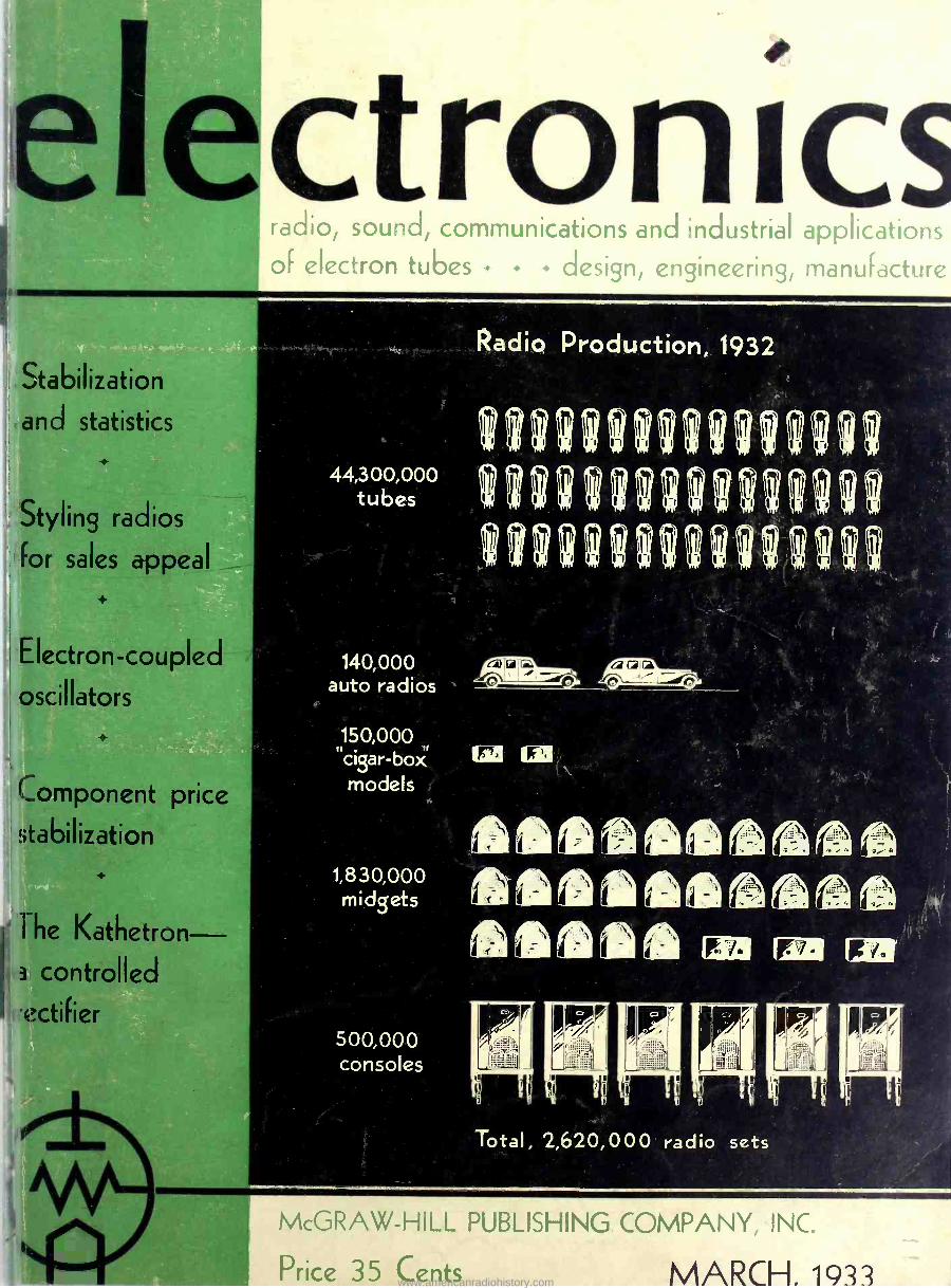
Radio Production, 1932
44t3zos0o undulievnine Indeerneefl?n
140,000 auto radios
150,000 "cigar- boa' models
1,830,000 midgets
500,000 consoles
Total, 2,620,000 radio sets
McGRAW-HILL PUBLISHING COMPANY, INC.
Price 35 Cents MARCH. 1933 www.americanradiohistory.com
C-P,70170//fettl OF ACCURATELY
FABRICATED PARTS
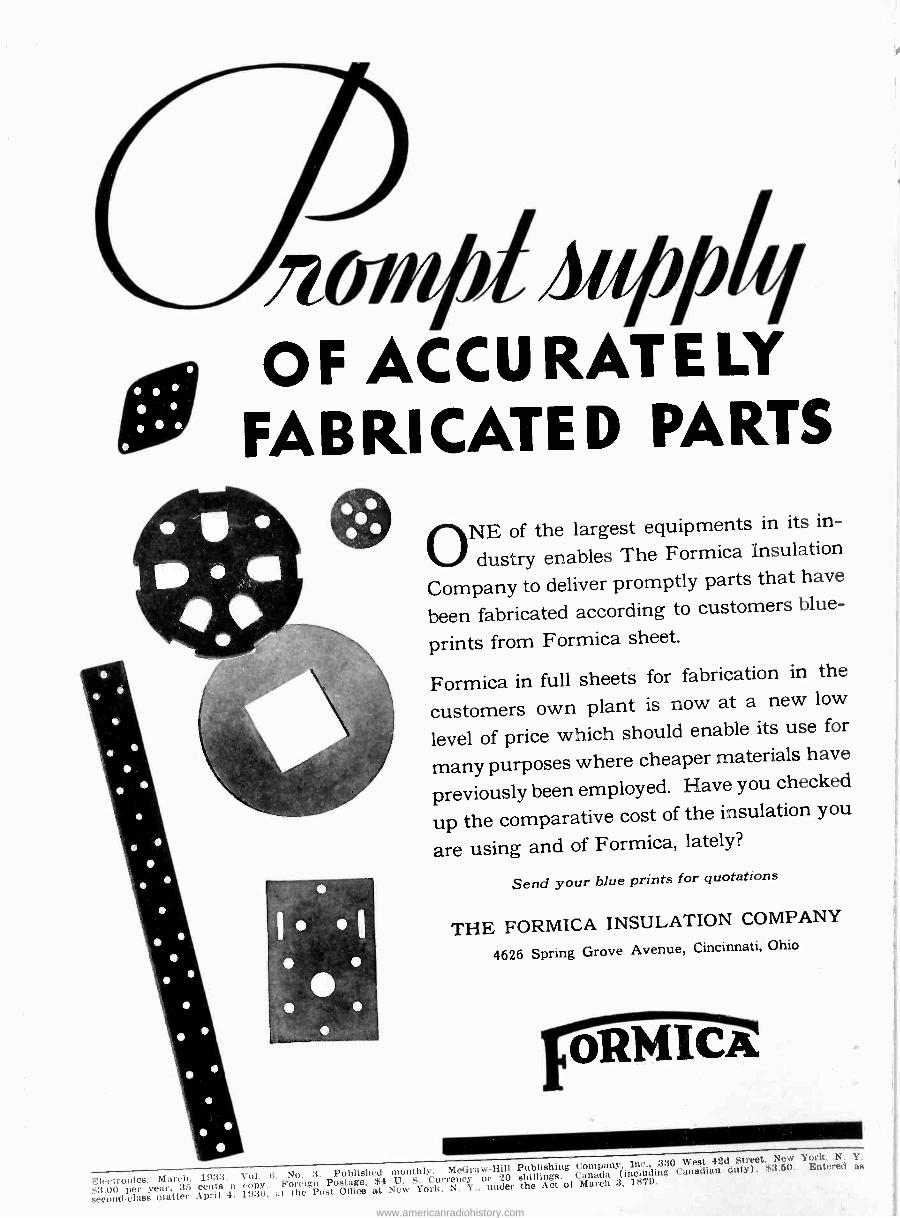
ONE of the largest equipments in its in-
dustry enables The Formica Insulation
Company to deliver promptly parts that have
been fabricated according to customers blue-
prints from Formica sheet.
Formica in full sheets for fabrication in the
customers own plant is now at a new low
level of price which should enable its use for
many purposes where cheaper materials have
previously been employed. Have you checked
up the comparative cost of the insulation you
are using and of Formica, lately?
Send your blue prints for quotations
THE FORMICA INSULATION COMPANY
4626 Spring Grove Avenue, Cincinnati, Ohio
0 -r -1-114-13a
Foreign Postage, $4 U. S. Currency or 20 shillings. Canada (including Canadian duty). $3.50. Entered as
Electronics, March, 1933. Vol. ti, No. 3. Published monthly. McGraw-Hill Publishing Company, Inc., 330 West 42d Street, New York,
$econ per year 35r centspril. 1930 1879.
second-class matter April 4, 1930, at the Post Office at New York, N. Y., under the Act of March 3,
www.americanradiohistory.com
A
electronics
radio
sound pictures
telephony
broadcasting
telegraphy
counting
grading
carrier systems
beam transmission
photo cells
facsimile
electric recording
amplifiers
phonographs
measurements
receivers
therapeutics
traffic control
musical instruments
machine control
television
metering
analysis
aviation
metallurgy
beacons
compasses
automatic processing
crime detection
geophysics
McGRAW-HILL PUBLISHING COMPANY, INC.
New York, March, 1933
O. H. CALDWELL Editor
KEITH HENNEY Associate Editor
Stabilization aná Profits
THE figures on radio production in this issue of Electronics picture the condition that exists in radio today. Reduction in
unit values, and the drop in total units sold, both point the need for stabilization. The time has come to get the radio industry onto a
sound, profit -making basis. It can be done. The popular interest in radio is as great or greater
than ever. Broadcast programs increase in interest and in impor- tance. The public continues to buy sets, and there are still millions of homes to be equipped or brought up to date.
IEADERSHIP in the job of building back toward stabilizátion i must come from the manufacturing end. Distributors and
dealers, of course, need to reform practices that too often spread merchandising destruction and carry down their own businesses in the melee. But changes in the manufacturing set-up are fundamental to any continuing reforms that come in the distribution end.
With recent changes in the Radio Manufacturers Association's plan of operation, and with the settlement of the Government's suit against the Radio Corporation, the raw materials seem at hand to
get stabilization. Licensing authority is now placed unmistakably in RCA's hands, and should be administered in a way to stimulate a
healthy production situation, without destructive surplus. RCA's responsibility is that of leadership and control. Meanwhile the radio producers can help radio's renaissance by suppressing rampant indi- vidualism and becoming more group -minded.
EVERY opportunity is now given to the responsible heads of radio manufacture to get together and show the way towards stabiliza-
tion and profits for the industry.
www.americanradiohistory.com
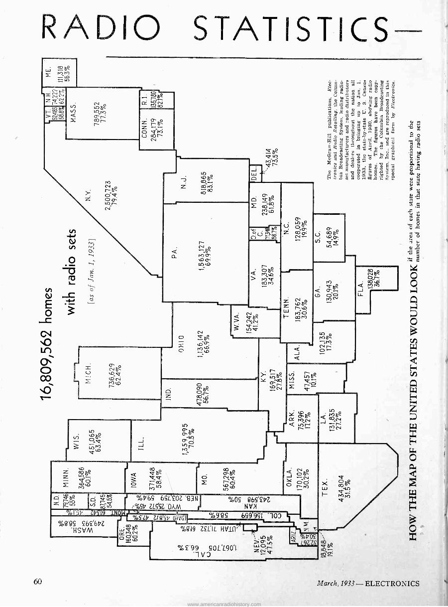
RADIO STATISTICS 40
Lll MK? Lc)
'°o U.)
N o L[')M r cor r
O t" ea 6-2
M co
rr
v- 6 ó U -co
2
gz- r ̀c' 5b t7 ' I
V389 262`6bZ HSdM
co V_V
o oó M
Vob65 65L`£OZ 93N
_°49t7 ZLAZ .OAM C
1b ZLSSb OH'QyQl,p
%419 ZfLlL HtII(1`
°.1405 965'£t7Z Nd
1:.
°. p ii! -'114::41 c, 33,,*.
bn e: ' º m GO N
e ,wg b j g Ñ
í7v
Q ?d
e
1 iv
v44'äA ßm)ra Óe A
ti ` A
atlçmvo.oM4R°s m -
.
.9p' ó w
01 b ID, Ñ ° A m cti m C i
', 5 i I -m,qm 2m 2O 2
C ß F ea^ dcáhi m
M Ñ °
9 I 2 * mm g m
ßM c.
m'mg b oCqgq H.°.;A amo pW Ú.-I W..Fm fe
á -J
Lr -o r _
V"
f
%9.9c 659951 100
%£-99 90L'L901 .1d3
,a
v
60 March, 1933- ELECTRONICS
www.americanradiohistory.com
PRODUCTION AND USE
Alabama Arizona... ...... Arkansas .......... California.......... .
Colorado.
Connecticut........ Delaware.... .. .
Dist. of Columbia.... Florida Georgia.... .. .
Idaho.... . ...... Illinois ............ Indiana Iowa ............... Kansas... ......
Kentucky. Louisiana Maine. Maryland... ... Massachusetts
Michigan........... Minnesota.......... Mississippi.... .... .
Missouri. Montana ..........
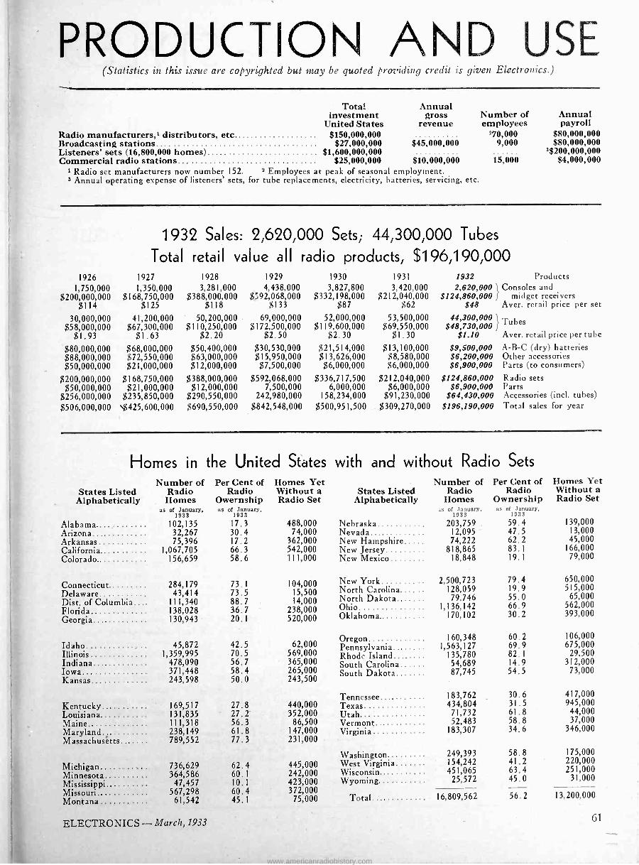
(Statistics in this issue are copyrighted but may be quoted providing credit is given Electronics.)
Total investment
United States Radio manufacturers,' distributors, etc. $150,000,000 Broadcasting stations.. . ...................... $27,000,000 Listeners' sets (16,800,000 homes) $1,600,000,000 Commercial radio stations... .. . ................. ..... $25,000,000
Annual gross
revenue
$45,000,000
$10000,000 Radio set manufacturers now number 152. 2 Employees at peak of seasonal employment.
3 Annual operating expense of listeners' sets, for tube replacements, electricity, batteries, servicing, etc.
Number of employees
'70,000 9,000
15,000
Annual payroll
$80,000,000 $80,000,000
3$200,000,000 $4,000,000
1932 Sales: 2,620,000 Sets; 44,300,000 Tubes
Total retail value all radio products, $196,190,000 1926 1927 1928 1929 1930 1931 1932 Products
1,750,000 1,350,000 3,281,000 4,438,000 3,827,800 3,420,000 2,620,000 Consoles and $200,000,000 $168,750,000 $388,000,000 $;92,068,000 $332,198,000 $212,0$460,000 $124,860,000 f midget receivers
$114 $125 $118 $133 $87 $48 Aver. retail price per set
30,000,000 $58,000,000
41,200,000 $67,300,000
50,200,000 $110,250,000
69,000,000 $172,500,000
52,000,000 $119,600,000
53,500,000 $69,550,000
44,300,000 l Tubes $48,730,000 f $1.93 $1.63 $2.20 $2.50 $2.30 $1.30 $1.10 Aver. retail price per tube
$80,000,000 $68,000,000 $50,400,000 $30, 530,000 $21,514,000 $13,100,000 $9,500,000 A -B -C (dry) batteries $88,000,000 $72,550,000 $63,000,000 $15,950,000 $13,626,000 $8,580,000 $6,200,000 Other accessories $50,000,000 $21,000,000 $12,000,000 $7,500,000 $6,000,000 $6,000,000 $6,900,000 Parts (to consumers)
$200,000,000 $168,750,000 $388,000,000 $592,068,000 $336,717,500 $212,040,000 $124,860,000 Radio sets $50,000,000 $21,000,000 $12,000,000 7,500,000 6,000,000 $6,000,000 $6,900,000 Parts
$256,000,000 $235,850,000 $290,550,000 242,980,000 158,234,000 $91,230,000 $64,430,000 Accessories (incl. tubes) $506,000,000 $425,600,000 $690,550,000 $842,548,000 $500,951,500 $309,270,000 $196,190,000 Total sales for year
Homes in the United States Number of Per Cent of
States Listed Radio Radio Alphabetically Homes Owernship
as of January, as of January, 1933 1933
102,135 17.3 488,000 32,267 30.4 74,000 75,396 17.2 362,000
1,067,705 66.3 542,000 156,659 58.6 111,000
Homes Yet Without a Radio Set
284,179 73.1 104,000 43,414 73.5 15,500
111,340 88.7 14,000 138,028 36.7 238,000 130,943 20.1 520,000
45,872 42.5 62,000 1,359,995 70.5 569,000
478,090 56.7 365,000 371,448 58.4 265,000 243,598 50.0 243,500
169,517 27.8 440,000 131,835 27.2 352,000 111,318 56.3 86,500 238,149 61.8 147,000 789,552 77.3 231,000
736,629 62.4 445,000 364,586 60.1 242,000
47,457 10.1 423,000 567,298 60.4 372,000
61,542 45.1 75,000
with and without Radio Sets
States Listed Alphabetically
Nebraska.......... Nevada._ New Hampshire.... .
New Jersey......... New Mexico .......
New York... North Carolina...... North Dakota....... Ohio Oklahoma...........
Number of Radio
Homes as of January,
1933
203,759 _
12,095 74,222
818,865 18,848
2,500,723 128,059 79,746
1,136,142 170,102
Oregon ............. 160,348 Pennsylvania........ 1,563,127 Rhode Island... ..... 135,780 South Carolina...... 54,689 South Dakota .. 87,745
Tennessee.......... .
Texas.... ...... Vermont........... .
Virginia............
Washington......... West Virginia Wisconsin......... Wyoming
183,762 434,804
71,732 52,483
183,307
249,393 154,242 451,065
25,572
Total........ ..... 16, 809, 562
Per Cent of Radio
Ownership as of January,
1933
59.4 47.5 62.2 83.1 19.1
79.4 19.9 55.0 66.9 30.2
60.2 69.9 82.1 14.9 54.5
30.6 31.5 61.8 58.8 34.6
58.8 41.2 63.4 45.0
Homes Yet Without a Radio Set
139,000 13,000 45,000
166,000 79,000
650,000 515,000
65,000 562,000 393,000
106,000 675,000 29,500
312,000 73,000
417,000 945,000
44,000 37,000
346,000
175,000 220,000 251,000
31,000
56.2 13,200,000
ELECTRONICS -March, 1933 61
www.americanradiohistory.com

When will Radios be STYLED
Mr. Teague is consultant on the design of the products of the Corning Glass Works, Eastman Kodak Company, Bausch & Lomb Optical Company, Taylor Instrument Com- panies, etc. He designed the body of the Marmon Sixteen car, which has had a profound influence on automobile styles in this country. He also designed the Kodak Shop at 745 Fifth Ave., New York City, and has recently completed a series of designs of "Century of Progress" silks for Marshall Field & Co. Among his other clients are Thomas A. Edison, Inc.; National Radiator Corporation, National Carbon Com- pany, General Register Corporation, Square D Company, etc. He has designed many packages and a wide range of prod- ucts, including pianos, gas boilers, calculating machines, cameras, temperature and weather instruments, optical instru- ments, furniture and rugs.
N.OT
so long ago I was asked by the president of a large radio manufacturing corporation to pass judgment, as a matter of courtesy, on two models
for radio cabinets. It was an embarrassing moment :
at first glance I could not see that either was less baci than the other ; both looked exactly like all the radio cabinets I had seen advertised or displayed-that is, both looked like the devil.
Both were designed in that jig -saw school of art which flourished in the General Grant period in architecture, and in furniture survives only in the "Your -Credit -Is -
Present sets still in
"Model I stage
says
WALTER DORWIN TEAGUE
Good -With -Us" instalment houses ; both were plastered with imitation carving and loaded with machined mould- ings and lathe turnings ; and both had some faint reminiscence of a "period" which was an excuse for call- ing them "Queen Anne" or "Tudor" or what not.
On close comparison I realized that one bore slightly less of this ginger -bread than the other and I was able to give it a feeble preference.
Now this executive, who took these cabinets seriously and believed that their differences would have an effect on sales, was a man of culture and good taste. I am sure that his home is attractively furnished and that he would scorn to give house -room to any piece of furni- ture in the least like these cabinets. Yet he was too close to his own business and so imbued with his industry's viewpoint that he took it for granted that radio cabinets
must look like that ;
and because his cab- inets were well built and because their jig- saw work and imita- tion carving differed from that on compet- ing lines, he believed his line was distinctive. He saw differences where I am sure, from t h e buying public's viewpoint, no differ- ence existed.
I am a fairly ob- serving person, espe- cially in matters of design - my business makes me so. And I assure you I know none of the standard lines of radio cabinets which is sufficiently distinctive or superior to be recognizable at sight. It is obvious that they all come out of the same hopper and represent the
National Alliance of Art and Industry to hold clinic on
"How to Style Radio Sets for Increased Sales," March 20 Luncheon meeting, Monday, March 20, 12:30 p.m., at Hotel White, Lexington Ave., at 37th St.,
New York City. This meeting will be one of the regular large "clinics" held by the National Alliance for the purpose of promoting cooperation between industry executives and designers. These clinics have been widely attended by industrial leaders in many fields, and have had great influence on subsequent designs in those industries.
The program as planned at the time "Electronics" goes to press, will include brief talks by leading merchants and designers, pointing out the need for styling radio sets, and the possibilities in this field. Grover Whalen, general manager Wanamaker's, New York City. Kenneth Collins, formerly with Macy's, now with Gimbel's, New York City. Henry Dreyfuss, designer, New York. George Sakier, designer, New York. Richard DeWolfe Brixey is president of the National Alliance, and Alon Bernent is director. Its headquarters are located in the Art Center Building, 65 East 56th Street, New York City. At the request of "Electronics" the National Alliance office has supplied the following alphabetica list of qualified designers who have done work in the fields of various industrial products.
Lucian Bernhard Norman Bel Geddes Christoph Castou Donald Deskey Henry Dreyfuss Helen Dryden Paul Frankl
Hugo Gnam Lurelle Guild Vahan Hagopian W. S. Harrison Wolfgang Hoffman Gustav Jensen Alexander Kachinsky
William Lescaze Ray Loewy J. D. Peters Winold Reiss Gilbert Rohde George Sakier Joseph Sinel
Lee Simonson Eugene Schoen Walter Dorwin Teague Harold L. VanDoren Kern Weber Russell Wright
Addresses of these designers can be supplied by "Electronics," 330 W. 42nd St., New York.
62 March, 1933 -- ELECTRONICS
www.americanradiohistory.com
for SALES APPEAL? same conception of design-a conception which has made the radio industry most backward, from the point of view of design, of all the major industries.
Where there is so little to choose, all competitors may be said to be equal. But that the industry as a whole has been adversely affected is proven to my own satis- faction by the fact that scores of persons in all walks of life have complained to me of their inability to find a "decent looking" radio cabinet which they would be willing to put in their living rooms; many others I know have devised cabinets of their own; and countless others have bought cheaper and smaller sets than they could well afford simply because the less obtrusive cabinet makes less of an eye -sore in their homes.
Why should the youngest, most modern, and otherwise most progressive of the major industries be so hopelessly bogged in this one particular? Why does it seem to feel that its up-to-the-minute product must be offered in a disguise-with an apologetic effort to make it look like something it isn't, like something our grandmothers might have owned if our grandmothers had had exces- sively bad taste? Why does it ignore the trend of popular taste in home furnishings, the growing appre- ciation of sound design, the leadership of all the many magazines devoted to interior arrangement and decora- tion? And why does it fail to profit by the experience of other industries in which new and good design has been used to advance sales and pyramid profits?
Some of the answers are obvious, the principal reason, I believe, being that the necessity for keeping down costs has forced the use of sources of supply, in many instances, that are singularly lacking in vision; plus the "follow-my-leader" spirit to be found in all large indus- tries ; plus the fact that one or two efforts to import an outside viewpoint resulted in dismal failures. (I think I know the reasons for this last, but as I have only sus- picions to go on they shall be unvoiced).
Radio's stalemate will not last
But no industry can remain stalemated forever. Some one is bound to step out of line and make a wholly fresh approach to this cabinet problem, producing a line of cabinets that will instantly register on the public consciousness by their individuality, and sweep the mar- ket because of their beauty and appropriateness. It would not be a difficult thing to do, given a designer of real creative ability and a manufacturing organization imbued with a spirit of enthusiastic cooperation.
We shall then see something closely paralleling the history of the automobile industry, which certainly has the "follow-my-leader" spirit as strongly as any other. In the automobile world, every major success for years past has been the result. of a decided and advanced in- novation in design; and every one of these steps forward has been in the same direction-further away from the original carriage type, closer and closer to the ideal of a stream -lined, motor -driven projectile. After each one of these popular successes there has been a scurrying effort by other manufacturers to pull their models up to the new level ; and they have then marked time until some one with vision and confidence has shown them the next step.
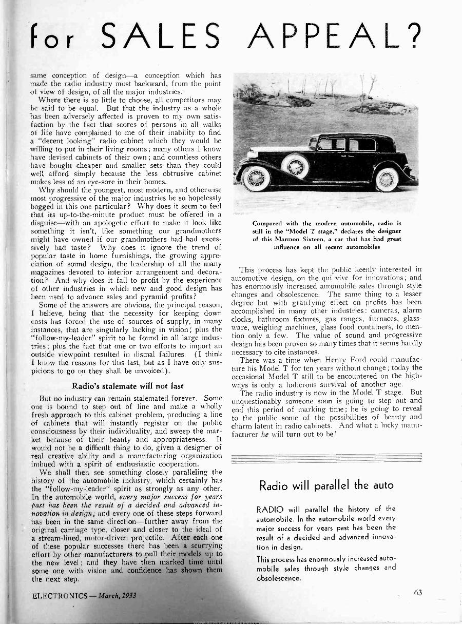
Compared with the modern automobile, radio is still in the "Model T stage," declares the designer of this Marmon Sixteen, a car that has had great
influence on all recent automobiles
This process has kept the public keenly interested in automotive design, on the qui vive for innovations ; and has enormously increased automobile sales through style changes and obsolescence. The same thing to a lesser degree but with gratifying effect on profits has been accomplished in many other industries : cameras, alarm clocks, bathroom fixtures, gas ranges, furnaces, glass- ware, weighing machines, glass food containers, to men- tion only a few. The value of sound and progressive design has been proven so many times that it seems hardly necessary to cite instances.
There was a time when Henry Ford could manufac- ture his Model T for ten years without change ; today the occasional Model T still to be encountered on the high- ways is only a ludicrous survival of another age.
The radio industry is now in the Model T stage. But unquestionably someone soon is going to step out and end this period of marking time ; he is going to reveal to the public some of the possibilities of beauty and charm latent in radio cabinets. And what a lucky manu- facturer he will turn out to be!
Radio will parallel the auto
RADIO will parallel the history of the
automobile. In the automobile world every
major success for years past has been the
result of a decided and advanced innova-
tion in design.
This process has enormously increased auto-
mobile sales through style changes and
obsolescence.
ELECTRONICS- March, 1933 63
www.americanradiohistory.com

Prices of
components tend
to stabilize
New tubes, models
still plague the industry
C( )\IPONENTS and raw material manufacturers, supplying the radio industry with the parts out of which sets are made, like the rest of the world,
have felt the east wind. Prices have dropped during a year from 25 to 50 per cent and even more in some cases. Coils, condensers, resistors, insulation, metals- all have come down and seem to be approaching, asymptotically, a more or less stabilized level.
Tube manufacturers have engaged in a money wasting campaign to increase the numbers of tubes ; each new model a manufacturer takes on costs about $5,000, which represents the profits on many tubes. And yet so anxious are the manufacturers to hurry the day of doom they will bring out a new type only to discover that an existing type with slight variations in recommended volt- ages will produce exactly the same result !
Old-line set manufacturers, caught napping by the "universal" fad, have watched 100,000 of the a.c.-d.c. sets go into the market each representing a profit to the maker, to the dealer, and supposedly to the buyer ; and in this case the maker is a manufacturer from whom little has been heard previously.
Components prices Among the parts going into radio sets the case of
coils is characteristic. A year ago prices were coming down but quality was holding up pretty well. Now everything is going by the board in the race to get busi- ness at lower prices. The vest-pocket type of set using a two -gang condenser has four tuned circuits. A manufacturer will pay about as much for the two coils as he would for single coils a year ago.
Electrolytic condensers of the dry type, selling at 27 cents per 8-µ f have maintained their price very well, largely because of the license situation. All dry con- densers are licensed by one company; therefore it is not difficult to keep the selling prices at a profitable level. The trouble with this situation is that the wet condenser which does not enjoy any such stabilizing influ- ence is getting more and more of the total condenser business. These condensers can be sold about 5 cents
lower per 8 -uf. Some readjustments in dry -condenser prices may be forced by this situation.
Volume controls that a year ago sold for 29 cents now bring 25 cents. Fixed resistors have gone down about 50 per cent. Units which brought seven to eight cents a year ago now are lucky to move at 3 cents.
New metals for tubes And so it goes. If prices do not come down, manu- facturers find a way to avoid the product. The tube industry is a good example. For five years, at least,
tube engineers have experimented with iron and other metals for plates and other structures now annually consuming many tons of nickel which is more expensive.
Now it appears that at least one company has mastered the art of using steel for anodes ; rumor has it that this company has gone 100 per cent to the metal ; other companies are learning the technique, and as soon as high inventories of nickel products are exhausted they may turn to steel. The Swedish Iron and Steel Com- pany (Electronics, December, 1932, page 379) has been very active in working with tube engineers. The National Carbon Company has developed extruded car- bon plates which are now being used in power tubes from the 210 in size up. This new development may find its way into the receiving tube business. At the same time new alloy wires are on the way for grids, etc. Allan Bradley has developed a carbon enamel for plates to reduce secondary emission.
It is possible that not all of these developments will work in the direction of reducing prices of making tubes ;
but anything that effects any decrease in cost will secure immediate attention from tube executives. The next move is to revamp or simplify processes-either by devel- oping new -methods, or by reducing quality.
Trends in set design The four -tube t.r.f. universal receiver seems to be
definitely out of the picture, after its exciting whirl, in favor of five -tube supers in about the same cabinet size. The next move, of course, is to so improve the four -tube set that it will again command the market (because it will be lower in price than a five -tube job). Tube makers have contributed much to the small set game. Combining two functions in one envelope reduces the space requirements.
Ultimately, perhaps, there will be a two -tube super. The first tube will be a detector -oscillator (Electronics, February, 1933, page 35, and this issue, page 76) and the second tube will be a detector -power output tube. This will reduce the receiver to its lowest terms-then the industry need no longer worry about reductions in the size of the midget. Indications are already in sight that manufacturers will abandon the intermediate set; there will be a very cheap model, and a better model.
All of these indications may or may not be favorable ;
certainly there are other trends that are distinctly favor- able. There are new receivers which are reported to excel the past art in fidelity and realism and power output. Loudspeakers are on the way that will transmit the higher frequencies better than existing speakers. New acoustic cabinet material, new forms of tone con- trol, and still other new features will aim to improve fidelity to a point easily demonstrable to the ear. In addition there will be a determined effort to bring beauty into cabinet design on the theory that if engineering excellence and low price cannot move radios, beauty of line will be more successful.
64 March, 1933 - ELECTRONICS
www.americanradiohistory.com
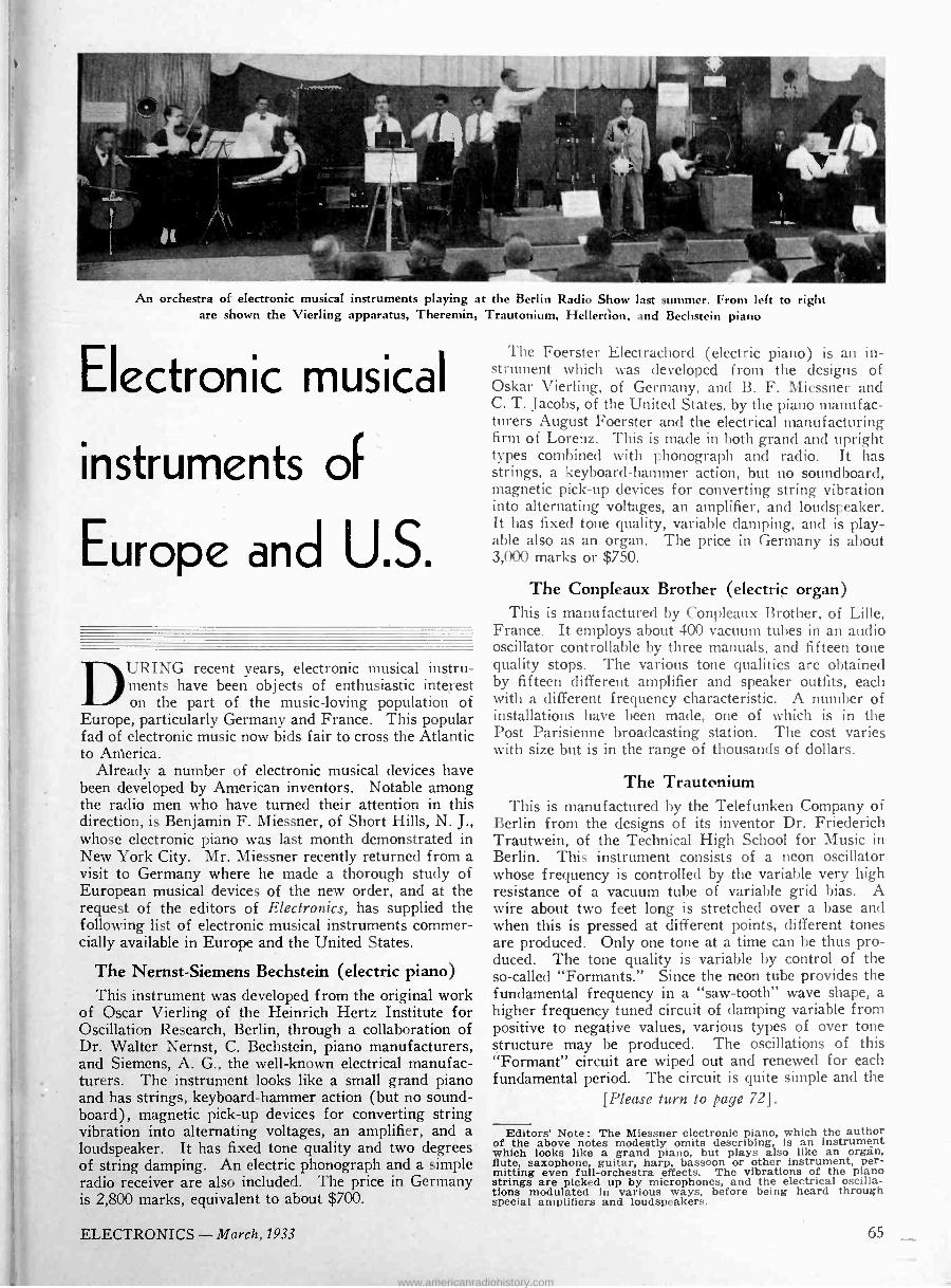
An orchestra of electronic musical instruments playing at the Berlin Radio Show last summer. From left to right are shown the Vierling apparatus, Theremin, Trautonium, Hellertlon, and Bechstein piano
Electronic musical
instruments of
Europe and U.S.
DURING recent years, electronic musical instru- ments have been objects of enthusiastic interest on the part of the music -loving population of
Europe, particularly Germany and France. This popular fad of electronic music now bids fair to cross the Atlantic to America.
Already a number of electronic musical devices have been developed by American inventors. Notable among the radio men who have turned their attention in this direction, is Benjamin F. Miessner, of Short Hills, N. J., whose electronic piano was last month demonstrated in New York City. Mr. Miessner recently returned from a visit to Germany where he made a thorough study of European musical devices of the new order, and at the request of the editors of Electronics, has supplied the following list of electronic musical instruments commer- cially available in Europe and the United States.
The Nernst -Siemens Bechstein (electric piano) This instrument was developed from the original work
of Oscar Vierling of the Heinrich Hertz Institute for Oscillation Research, Berlin, through a collaboration of Dr. Walter Nernst, C. Bechstein, piano manufacturers, and Siemens, A. G., the well-known electrical manufac- turers. The instrument looks like a small grand piano and has strings, keyboard -hammer action (but no sound - board), magnetic pick-up devices for converting string vibration into alternating voltages, an amplifier, and a loudspeaker. It has fixed tone quality and two degrees of string damping. An electric phonograph and a simple radio receiver are also included. The price in Germany is 2,800 marks, equivalent to about $700.
The Foerster Electrachord (electric piano) is an in- strument which was developed from the designs of Oskar Vierling, of Germany, and B. F. Miessner and C. T. Jacobs, of the United States, by the piano manufac- turers August Foerster and the electrical manufacturing firm of Lorenz. This is made in both grand and upright types combined with phonograph and radio. It has strings, a keyboard -hammer action, but no soundboard, magnetic pick-up devices for converting string vibration into alternating voltages, an amplifier, and loudspeaker. It has fixed tone quality, variable damping, and is play- able also as an organ. The price in Germany is about 3,000 marks or $750.
The Conpleaux Brother (electric organ) This is manufactured by Conpleaux Brother, of Lille,
France. It employs about 400 vacuum tubes in an audio oscillator controllable by three manuals, and fifteen tone quality stops. The various tone qualities are obtained by fifteen different amplifier and speaker outfits, each with a different frequency characteristic. A number of installations have been made, one of which is in the Post Parisienne broadcasting station. The cost varies with size but is in the range of thousands of dollars.
The Trautonium This is manufactured by the Telefunken Company of
Berlin from the designs of its inventor Dr. Friederich Trautwein, of the Technical High School for Music in Berlin. This instrument consists of a neon oscillator whose frequency is controlled by the variable very high resistance of a vacuum tube of variable grid bias. A wire about two feet long is stretched over a base and when this is pressed at different points, different tones are produced. Only one tone at a time can be thus pro- duced. The tone quality is variable by control of the so-called "Formants." Since the neon tube provides the fundamental frequency in a "saw -tooth" wave shape, a higher frequency tuned circuit of damping variable from positive to negative values, various types of over tone structure may be produced. The oscillations of this "Formant" circuit are wiped out and renewed for each fundamental period. The circuit is quite simple and the
[Please turn to page 72] .
Editors' Note : The Miessner electronic piano, which the author of the above notes modestly omits describing, is an instrument which looks like a grand piano, but plays also like an organ, flute, saxophone, guitar, harp, bassoon or other instrument, per- mitting even full -orchestra effects. The vibrations of the piano strings are picked up by microphones, and the electrical oscilla- tions modulated in various ways, before being heard through special amplifiers and loudspeakers.
ELECTRONICS -March, 1933 65
www.americanradiohistory.com
Proper sites For
broadcast stations
A radical proposal to improve receiving conditions
By C. W. HORN Chief Engineer, National Broadcasting Company, Inc.
N AN activity in which technical improvements cause changes as rapidly as in radio broadcasting it is essential that we revise our specifications at frequent
intervals. It is general engineering practice first to set up the problem which must be solved and then to utilize whatever means are available for designing and con- structing the most efficient equipment to meet that prob- lem. Theref ore as engineering development primarily attempts to overcome difficulties being experienced, it is fair to say that we must first have need or demand for improvements before they are forthcoming.
In fact one very effective way of encouraging advances in the art is to force the issue by setting up requirements, having as their aim the refinement and perfection of the general service to the public. This is well illustrated by the action of the Federal Radio Commission in demanding frequency stability which was met by manufacturers when they produced apparatus keeping the frequency of transmitters well within the 50 cycle tolerance which the Commission specified.
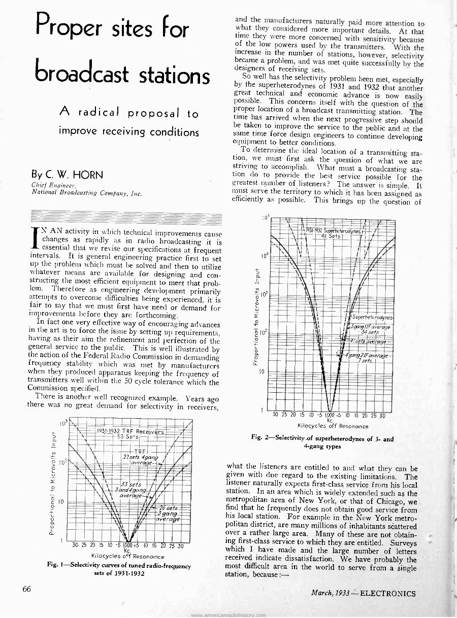
There is another well recognized example. Years ago there was no great demand for selectivity in receivers,
. I I I
1931-1932 TRF Receivers /,
,e . \ 53 Sets / \ \ / ¡ \ \ \ 27sets
TRF 4gang
averaqe--; I i , /*.
\ I
, / \ F
/ \ t 53 sets 3and4gang¡ \` average- 1
\. ;4_ 2bsets- .3gang= averaye-
` ` 1
l 1 .\ f
\
i
30 25 20 15 10 -5 1,000+5 10 15 20 25 30 Kc.
Kilocycles off Resonance Fig. 1-Selectivity curves of tuned radio -frequency
sets of 1931-1932
and the manufacturers naturally paid more attention to what they considered more important details. At that time they were more concerned with sensitivity because of the low powers used by the transmitters. With the increase in the number of stations, however, selectivity became a problem, and was met quite successfully by the designers of receiving sets. So well has the selectivity problem been met, especially by the superheterodynes of 1931 and 1932 that another great technical and economic advance is now easily possible. This concerns itself with the question of the proper location of a broadcast transmitting station. The time has arrived when the next progressive step should
be taken to improve the service to the public and at the same time force design engineers to continue developing equipment to better conditions. To determine the ideal location of a transmitting sta- tion, we must first ask the question of what we are striving to accomplish. What must a broadcasting sta-
tion do to provide the best service possible for the greatest number of listeners ? The answer is simple. It must serve the territory to which it has been assigned as efficiently as possible. This brings up the question of
105
o
lo
ma, 7m \= '31-9 41uSetsr
erodynes
111/5 11111
IIIIiIIid1I INVSuperheterodynes
,cp/IFavezrge
3415 . . verage
111111.1! 4gang2/Faverage 7sets
i :
30 25 20 15 10 -5 1,000 +5 10 15 2 25 30 Kc.
Kilocycles off Resonance
Fig. 2-Selectivity of superheterodynes of 3- and 4 -gang types
what the listeners are entitled to and what they can be given with due regard to the existing limitations. The listener naturally expects first-class service from his local station. In an area which is widely extended such as the metropolitan area of New York, or that of Chicago, we find that he frequently does not obtain good service from his local station. For example in the New York metro- politan district, are many millions of inhabitants scattered over a rather large area. Many of these are not obtain- ing first-class service to which they are entitled. Surveys which I have made and the large number of letters received indicate dissatisfaction. We have probably the most difficult area in the world to serve from a single station, because :-
66 March, 1933 - ELECTRONICS
www.americanradiohistory.com
It is large in extent: because steel structures of great magnitude throw radio shadows of considerable area ;
and because highly electrified conditions cause high noise levels.
Theref ore, additional factors must be considered in choosing the site for a transmitter, the importance of which greatly outweigh some of those taken into account when the rules now in existence were made.
If an illuminating engineer were told that he could use only one light and that that light could not exceed a certain value, and that it had to serve a particular area as efficiently as possible, he would naturally plot the area which must be covered and locate his light somewhere near the center of that territory. As radiations from a transmitting station follow in general the theory of light radiations, the problem is almost identical. It would be necessary for the illuririinating engineer to make sure that he did not blind people with too much light near the source of illumination, and to do this he would have to determine just how much light the eye could endure with- out discomfort. It is the same thing that we attempt to do in the case of a radio station. Fortunately the amount of power, even 50 kw., which is now the highest author- ized, is not so great an amount as to cause any real. difficulties at the present time.
The Federal Radio Commission has acted wisely in being conservative. I have no criticism of its general attitude but the time has arrived when new factors must be considered and perhaps a change made. I feel it is the duty of those in the technical field to bring such matters to the attention of the industry when it is felt that sufficient advances have been made to warrant changes. I feel that we can now locate stations to obtain greater efficiency because noticeable improvements have been made in overcoming the obstacles that prevented such a move prior to this time.
When so-called "high power" first came into being, the frequencies of transmitters were only approximate to those assigned. As the channels were 10 kc. apart a great deal of interference was encountered because it was difficult to keep a transmitter within even 1 kc. of its assigned frequency. Because the stations had com- paratively little power, the receiving set manufacturers solved the problem as they saw it by producing very sensitive sets. In making a receiver very sensitive they necessarily produced apparatus that was not highly selec- tive, and because of the novelty of radio the listener was intrigued with the possibility of receiving over great dis- tances.
Demise of the "dx" craze However, all this was in the days before networks,
and just as the far pastures seem to be the greenest, the listeners, becoming accustomed to the local programs, desired to hear other features from the more distant stations. Different stations put on highly attractive pro- grams and there was a great deal of complaining if the local stations caused any interference with reception from distant stations. All of this was logical because the listener had to tune around to obtain a program with some desirable talent. Even if only a limited number of stations could afford to put on an outstanding feature but once a week, many within a reasonable range attempted to receive that program. Before the days of networks the individual station could not afford to put on outstanding programs as a regular service and for many hours each day, because of lack of talent available in cities not a program center and because the expense was too great for a single station to undertake.
los
104
(i) 4-
ó 1Ó3 L u
lo
i
1931-1932 Receivers,All Types 94 Sets
Superheterodyne // average / 41se/s-.-->1
/ / /
i
i -rAverag T 99se{s
I i / /
0
/ TRF
average 53 sets
30 25 20 15 IO -5 1»000+5 10 15 20 25 30 Kc.
Kilocycles off Resonance
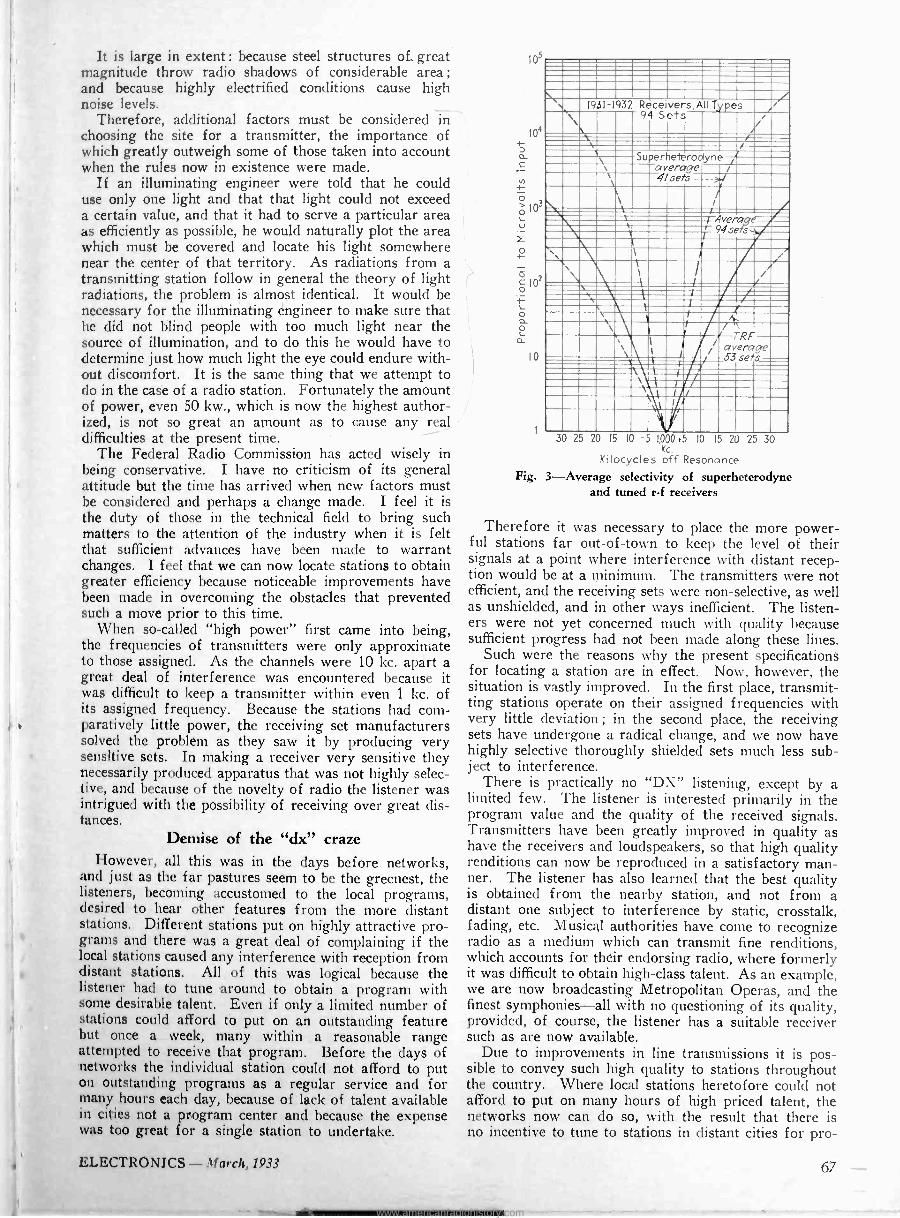
Fig. 3-Average selectivity of superheterodyne and tuned r -f receivers
Therefore it was necessary to place the more power- ful stations far out-of-town to keep the level of their signals at a point where interference with distant recep- tion would be at a minimum. The transmitters were not efficient, and the receiving sets were non -selective, as well as unshielded, and in other ways inefficient. The listen- ers were not yet concerned much with quality because sufficient progress had not been made along these lines.
Such were the reasons why the present specifications for locating a station are in effect. Now, however, the situation is vastly improved. In the first place, transmit- ting stations operate on their assigned frequencies with very little deviation ; in the second place, the receiving sets have undergone a radical change, and we now have highly selective thoroughly shielded sets much less sub- ject to interference.
There is practically no "DX" listening, except by a limited few. The listener is interested primarily in the program value and the quality of the received signals. Transmitters have been greatly improved in quality as have the receivers and loudspeakers, so that high quality renditions can now be reproduced in a satisfactory man- ner. The listener has also learned that the best quality is obtained from the nearby station, and not from a distant one subject to interference by static, crosstalk, fading, etc. Musical authorities have come to recognize radio as a medium which can transmit fine renditions, which accounts for their endorsing radio, where formerly it was difficult to obtain high-class talent. As an example, we are now broadcasting Metropolitan Operas, and the finest symphonies-all with no questioning of its quality, provided, of course, the listener has a suitable receiver such as are now available.
Due to improvements in line transmissions it is pos- sible to convey such high quality to stations throughout the country. Where local stations heretofore could not afford to put on many hours of high priced talent, the networks now can do so, with the result that there is no incentive to tune to stations in distant cities for pro -
4 ELECTRONICS - March, 1933 67
www.americanradiohistory.com

1,000
50 Kw. Broadcast Strength Vs.
Transmitter Distance Field
%%,1.e- 'Direction A
Direct Óñ B -' ..
0 I 2 3 4 5 6 7 6 9 10 II 2 13 14
Distance from Station in Miles
Field strength of a New York station in its best and poorest directions
grams which formerly could not be obtained locally. This is the strongest argument why the broadcast system should be readjusted to give the listeners improved service from stations located in their vicinity.
As an illustration of how the present system discrim- inates against this "ideal" which I have tried to bring out above, I might cite the case of stations in the Metro- politan area of New York. Because the present rules re- quire that a station utilizing 25 or 50 kw. must be located at a considerable distance from any population center a great hardship is caused to listeners residing in terri- tory on the far side of the city. In an area that is as large as the New York area a station located outside of the eastern borders of this dense population is very poorly received in the western portion of the territory. This is doubly true in the case of New York City because of the high attenuation due to steel structures. Stations located southwest of New York City are giving impaired service to many listeners in the north and eastern portions of the city. It is true of every large station in the New York area that they serve efficiently only a portion of the territory.
A remedy for sunspot radio disturbance Another f actor has become important during the last
two years. Because of sunspots, or whatever may be the cause, this last year has seen excellent sky wave transmit- ting conditions. Stations at quite a distance can occasion- ally be received- with a very strong signal. Theref ore, if the local station is not giving a strong signal, some interference is experienced from these neighboring channel stations, within what is called the ground -wave service area of the local station. Listeners have com- plained that they are not getting satisfactory service from the local station to which they feel entitled. They cannot tune to the distant stations for good service because these distant signals fade. and have merely a great annoyance value.
The solution is to raise the signal level of the local station throughout the territory it is serving. This terri- tory is the ground wave service area out to a point where fading may be expected. Merely raising the power of this local station does not always improve matters, for we know that it requires f our times as much power in the transmitter to give double the signal strength, and that added power is only partially effective, as doubling a weak signal does not help much, unless the receiver is at the border -line where just a little more signal would greatly improve matters.
The curves accompanying this article indicate the
degree of selectivity of the average receiving sets in use at the beginning of the year 1932. In order to be fair, these curves were made on a total of 94 receiving sets offered for sale by different manufacturers. Ut the more selective styles of receivers the curves indicate that the ratio of response of wanted to unwanted signal is as high as 1,000 to one in field strength when. 10 kc. removed. In the case of 20 kc. difference, the ratio is over 100,000 to one in the most selective types. Even in the least selective sets a ratio of 50 to one may be expected at 20 kc. separation.
As the Federal Radio Commission's regulations require a separation of 50 kc. between stations assigned to the same city, it is evident that modern receivers can be placed within a mile of a 50 -kw. station and have abso- lutely no difficulty receiving from any other local station in that locality. The only criticism which can be offered against this line of reasoning is that there are still in operation a considerable number of ancient non -selective receiving sets. To refuse or make impossible improved service to a large number of listeners because there are still a number of obsolete receivers in use controverts all ideas of progress. For there to be no progress until these obsolete receivers fall to pieces or die of old age is utterly unreasonable. Just as manufacturers will not build improved receivers unless there is the demand for them, just so will there be no improvement in general reception conditions until a situation «is created whereby these few obsolete receiving sets must be replaced.
Transmitters should be located near the listener Having demonstrated that progress in the art has
made it possible to locate transmitting stations quite close to densely populated centers without causing any more interference than was experienced a few years ago to these same listeners from a station quite far removed, I feel it is logical to suggest that transmitting stations now be permitted to find sites somewhere near the center of the territory to be served. In most areas it is pos- sible to find either highly industrialized sections or swamp areas, or other sparsely populated localities, somewhere near the center of the territory to be served. The only requirement now is that the least number of people possible live within a mile or less of such a site. Such localities exist quite near the center of New York which would serve admirably. This holds true for prac- tically every city, so that there is no need now of forcing the stations to locate well outside of the city. If all large stations were to group themselves in the same vicinity there would be no interference problem at all, even for the non -selective, obsolete receivers.
What would be the benefits if a 50 -kw. station were located somewhere near the center of the New York metropolitan area, for example in the Jersey meadows between the Palisades and Newark? Here are many miles of swamp land practically uninhabited, where it would be quite easy to find a site a mile or more from any considerable number of homes. A station located at this point would give a high quality usable signal to all of the densely inhabited portion of the metropolitan area. This signal would extend up beyond Bridgeport, Connecticut, over to Nassau and Queens, as well as Brooklyn, and would give excellent service to the sub- urban territory in Northern New Jersey in which several million people reside. Every one of the larger stations as located at present has a fading band and consequent poor service in a large portion of the territory it is intended to serve. By putting the station near the cen-
68 March,1933 - ELECTRONICS
www.americanradiohistory.com
ter of the area this fading band will be pushed out beyond the suburban areas.
Moving a station into town would therefore create a very large gain in service. In the case of the New York area millions of listeners or potential listeners would be given greatly improved service if advantage is taken of the improved design of transmitters and receivers which have been available f òr. more than a year past. There would be very little complaint, and this could auto- matically be taken care of by advice from radio editors of newspapers and general publicity. A broadcasting station is intended to serve the public which I interpret to mean the great majority and not a selected few /For this reason I feel that the Federal Radio Commission could very well change its requirements, and classify areas having a thousand or more millivolts per meter as blanket areas instead of the figure of 100 millivolts as at present. Radio manufacturers will give added attentioñ to more complete shielding and selectivity of receiving sets so that in time even 1000 millivolts can be exceeded.
In urban areas where the noise level is high, experi- ence has shown that at least a 10 -millivolt signal is neces- sary to insure interference -free service. Highly electri- fied areas like New York are not receiving such service at present. Only a small portion of the total area is in the ten -millivolt line of any one of the stations. There - f ore, listeners in such an area as New York are receiving poorer service than smaller cities throughout the country.
I f eel that we have reached the point where such a change is desirable, and that we must begin to think of radio problems from a "system" standpoint, rather than the way we have been doing heretofore. Formerly the transmitting engineer solved his problems, and the receiving engineer did the same in his field. The time has arrived when the broadcasting system engineer is the one who should set the specifications, and in cooperation with the transmitting and receiving engineers, develop apparatus so as to engineer the whole problem as a system of distribution for the benefit of the greatest number.
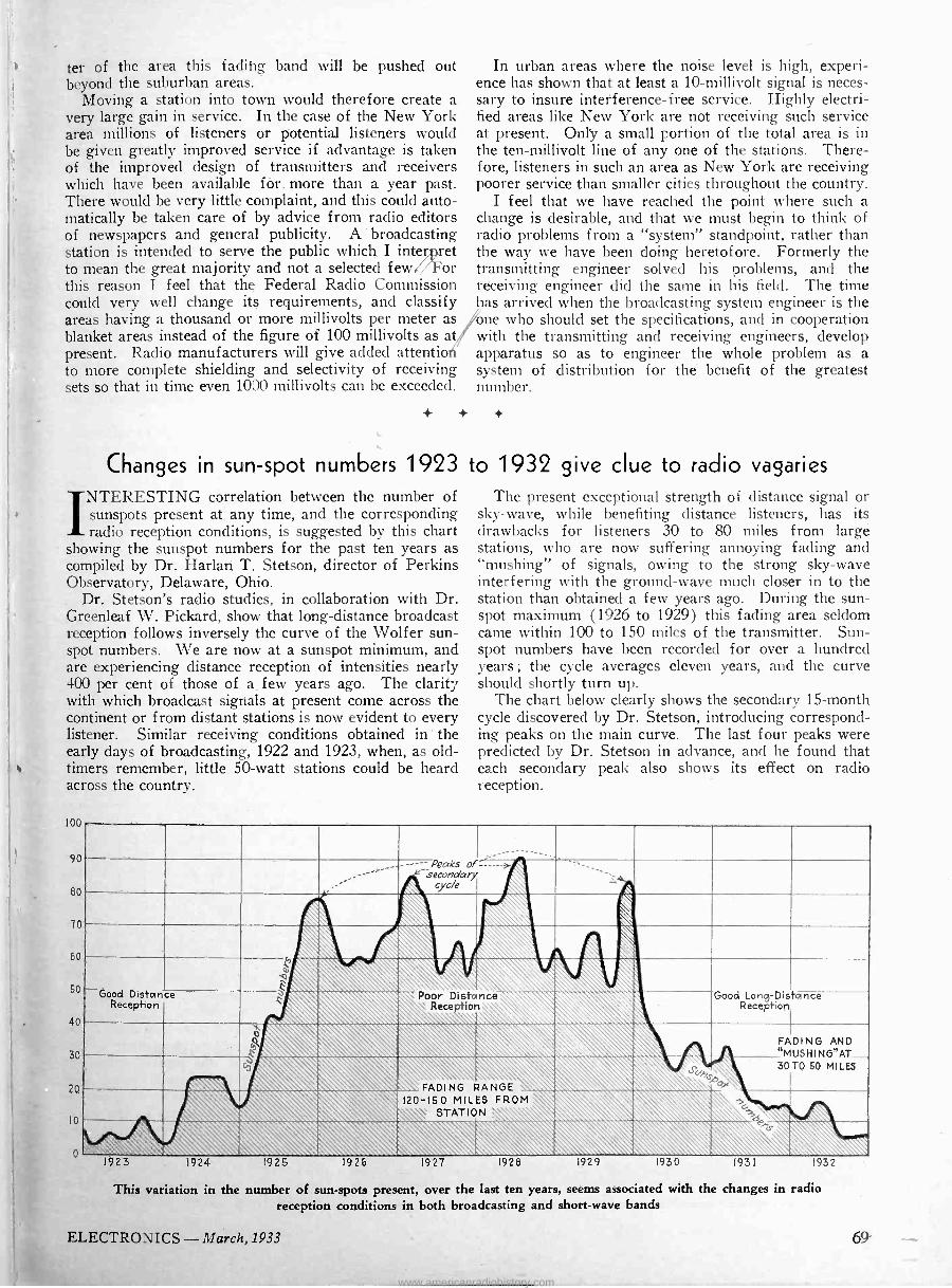
Changes in sun -spot numbers 1923 to 1932 give clue to radio vagaries
NTERESTING correlation between the number of sunspots present at any time, and the corresponding radio reception conditions, is suggested by this chart
showing the sunspot numbers for the past ten years as compiled by Dr. Harlan T. Stetson, director of Perkins Observatory, Delaware, Ohio.
Dr. Stetson's radio studies, in collaboration with Dr. Greenleaf W. Pickard, show that long-distance broadcast reception follows inversely the curve of the Wolfer sun- spot numbers. We are now at a sunspot minimum, and are experiencing distance reception of intensities nearly 400 per cent of those of a few years ago. The clarity with which broadcast signals at present come across the continent or from distant stations is now evident to every listener. Similar receiving conditions obtained in' the early days of broadcasting, 1922 and 1923, when, as old- timers remember, little 50 -watt stations could be heard across the country.
loo
90
80
70
60
50
40
30
20
l0
0
The present exceptional strength of distance signal or sky -wave, while benefiting distance listeners, has its drawbacks for listeners 30 to 80 miles from large stations, who are now suffering annoying fading and "mushing" of signals, owing to the strong sky -wave interfering with the ground -wave much closer in to the station than obtained a few years ago. During the sun- spot maximum (1926 to 1929) this fading area seldom came within 100 to 150 miles of the transmitter. Sun- spot numbers have been recorded for over a hundred years; the cycle averages eleven years, and the curve should shortly turn up.
The chart below clearly shows the secondary 15 -month cycle discovered by Dr. Stetson, introducing correspond- ing peaks on the main curve. The last f our peaks were predicted by Dr. Stetson in advance, and he found that each secondary peak also shows its effect on radio reception.
_ -----Peaks of------- 'secondary .\ cycle
C
Good Distance Reception
\ L' \\ Good Long -Distance
Reception t \\\ \ Poor Distance \ Rece ion \ \ Q\ \
\co Uhsp`
FADING MUSHING
30
AND AT_
T0 50 MILES N\\ \ FA DI \ \ \\ ̀\ 120-5 0 MILES l STATION
\ROM XG6 \ «, O_.Q 1 1923 1924 1925 1926 1927 1928 1929 1930 1931 1932
This variation in the number of sun -spots present, over the last ten years, seems associated with the changes in radio reception conditions in both broadcasting and short-wave bands
ELECTRONICS - March, 1933
www.americanradiohistory.com
The Kathetron
A control tube
with external grid
By PALMER H. CRAIG, Ph. D. The In vex Corporation
THE name Kathetron is derived from the Greek verb xa9£w meaning to control. It is applied to a gaseous discharge tube with an external grid
which controls the anode current either by variable poten- tial on this grid or by means of a changing phase relation between this potential and that of the arc itself.
The fundamental circuit of this variable amplitude voltage control is shown in Fig. la, where is a trans- former for supplying potential to an external grid C, which is placed around a mercury vapor rectifier tube. The arm to the variable resistor allows a greater or less potential to be impressed between the external grid and the cathode. Equally good, and in some cases better control is obtained when this variable potential is im- pressed between the external grid and the anode. By
Load Load
a b
Fig. 1-Fundamental circuits of the Kathetron tube
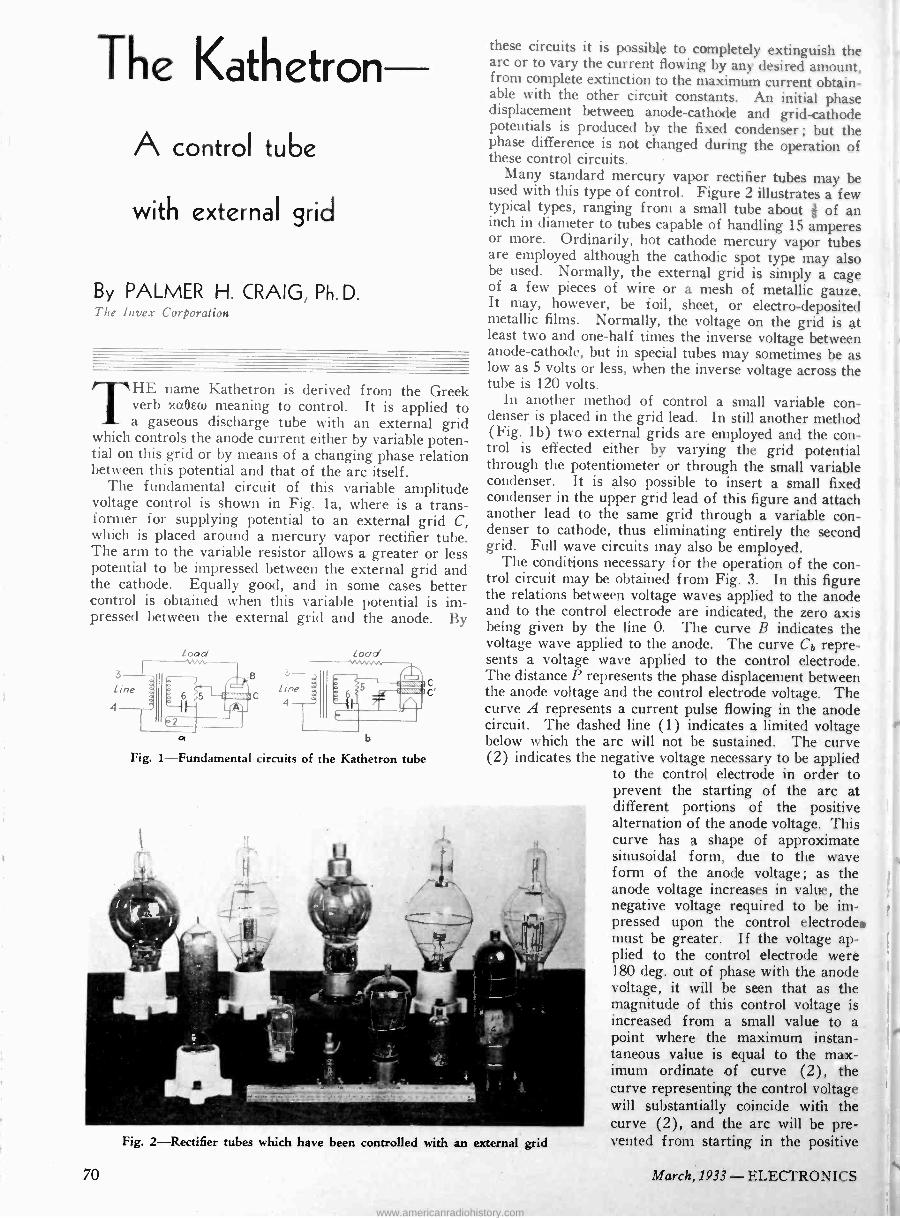
Fig. 2-Rectifier tubes which have been controlled with an external grid
these circuits it is possible to completely extinguish the arc or to vary the current flowing by any desired amount, from complete extinction to the maximum current obtain- able with the other circuit constants. An initial phase displacement between anode -cathode and grid -cathode potentials is produced by the fixed condenser ; but the phase difference is not changed during the operation of these control circuits.
Many standard mercury vapor rectifier tubes may be used with this type of control. Figure 2 illustrates a few typical types, ranging from a small tube about of an inch in diameter to tubes capable of handling 15 amperes or more. Ordinarily, hot cathode mercury vapor tubes are employed although the cathodic spot type may also be used. Normally, the external grid is simply a cage of a few pieces of wire or a mesh of metallic gauze. It may, however, be foil, sheet, or electro -deposited metallic films. Normally, the voltage on the grid is at least two and one-half times the inverse voltage between anode -cathode, but in special tubes may sometimes be as low as 5 volts or less, when the inverse voltage across the tube is 120 volts.
In another method of control a small variable con- denser is placed in the grid lead. In still another method (Fig. lb) two external grids are employed and the con- trol is effected either by varying the grid potential through the potentiometer or through the small variable condenser. It is also possible to insert a small fixed condenser in the upper grid lead of this figure and attach another lead to the same grid through a variable con- denser to cathode, thus eliminating entirely the second grid. Full wave circuits may also be employed.
The conditions necessary for the operation of the con- trol circuit may be obtained from Fig. 3. In this figure the relations between voltage waves applied to the anode and to the control electrode are indicated, the zero axis being given by the line O. The curve B indicates the voltage wave applied to the anode. The curve Cb repre- sents a voltage wave applied to the control electrode. The distance P represents the phase displacement between the anode voltage and the control electrode voltage. The curve A represents a current pulse flowing in the anode circuit. The dashed line (1) indicates a limited voltage below which the arc will not be sustained. The curve (2) indicates the negative voltage necessary to be applied
to the control electrode in order to prevent the starting of the arc at different portions of the positive alternation of the anode voltage. This curve has a shape of approximate sinusoidal form, due to the wave form of the anode voltage ; as the anode voltage increases in value, the negative voltage required to be im- pressed upon the control electrode. must be greater. If the voltage ap- plied to the control electrode were 180 deg. out of phase with the anode voltage, it will be seen that as the magnitude of this control voltage is increased from a small value to a point where the maximum instan- taneous value is equal to the max- imum ordinate of curve (2), the curve representing the control voltage will substantially coincide with the curve (2), and the arc will be pre- vented from starting in the positive
70 March, 1933 - ELECTRONICS
www.americanradiohistory.com
e
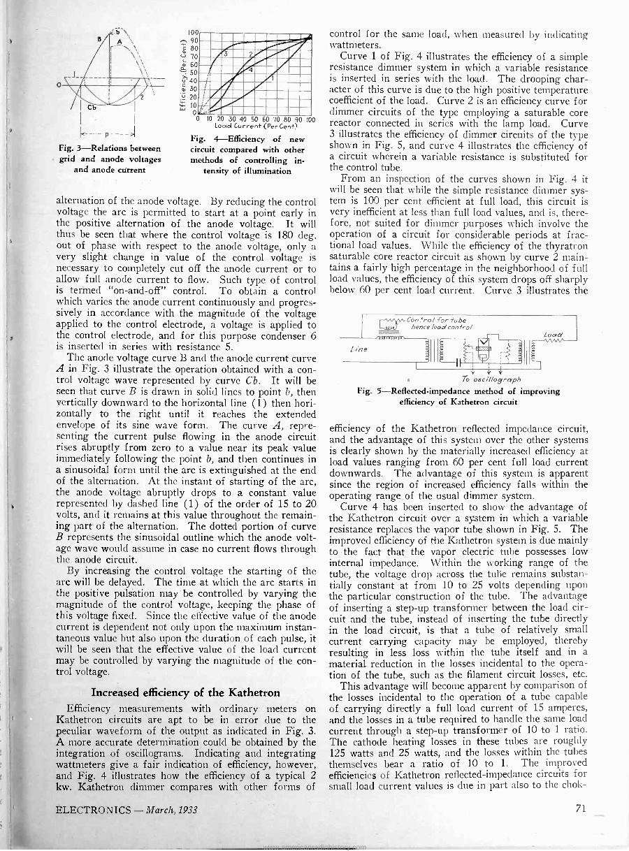
Fig. 3-Relations between grid and anode voltages
and anode current
100
90
`w 80
c-) 70
á 60 50
u 40 g 30
. 20
w 10
00 IO 20 30 40 50 60 70 80 90 100 Load Curren+ (Per Cent?
Fig. 4-Efficiency of new circuit compared with other methods of controlling in-
tensity of illumination
Rum nommwen, ammignmom%%n 4i nda wimmismenom H11KOZIIIMMENIMII E11IIMIZIMIZINIZI
alternation of the anode voltage. By reducing the control voltage the arc is permitted to start at a point early in the positive alternation of the anode voltage. It will thus be seen that where the control voltage is 180 deg. out of phase with respect to the anode voltage, only a very slight change in value of the control voltage is necessary to completely cut off the anode current or to allow full anode current to flow. Such type of control is termed "on -and -off" control. To obtain a control which varies the anode current continuously and progres- sively in accordance with the magnitude of the voltage applied to the control electrode, a voltage is applied to the control electrode, and for this purpose condenser 6 is inserted in series with resistance 5.
The anode voltage curve B and the anode current curve A in Fig. 3 illustrate the operation obtained with a con- trol voltage wave represented by curve Cb. It will be seen that curve B is drawn in solid lines to point b, then vertically downward to the horizontal line (1) then hori- zontally to the right until it reaches the extended envelope of its sine wave form. The curve A, repre- senting the current pulse flowing in the anode circuit rises abruptly from zero to a value near its peak value immediately following the point b, and then continues in a sinusoidal form until the arc is extinguished at the end of the alternation. At the instant of starting of the arc, the anode voltage abruptly drops to a constant value represented by dashed line (1) of the order of 15 to 20 volts, and it remains at this value throughout the remain- ing part of the alternation. The dotted portion of curve B represents the, sinusoidal outline which the anode volt- age wave would assume in case no current flows through the anode circuit.
By increasing the control voltage the starting of the arc will be delayed. The time at which the arc starts in the positive pulsation may be controlled by varying the magnitude of the control voltage, keeping the phase of this voltage fixed. Since the effective value of the anode current is dependent not only upon the maximum instan- taneous value but also upon the duration of each pulse, it will be seen that the effective value of the load current may be controlled by varying the magnitude of the con- trol voltage.
Increased efficiency of the Kathetron Efficiency measurements with ordinary meters on
Kathetron circuits are apt to be in error due to the peculiar waveform of the output as indicated in Fig. 3. A more accurate determination could be obtained by the integration of oscillograms. Indicating and integrating wattmeters give a f air indication of efficiency, however, and Fig. 4 illustrates how the efficiency of a typical 2 kw. Kathetron dimmer compares with other forms of
control for the same load, when measured by indicating wattmeters.
Curve 1 of Fig. 4 illustrates the efficiency of a simple resistance dimmer system in which a variable resistance is inserted in series with the load. The drooping char- acter of this curve is due to the high positive temperature coefficient of the load. Curve 2 is an efficiency curve for dimmer circuits of the type employing a saturable core reactor connected in series with the lamp load. Curve 3 illustrates the efficiency of dimmer circuits of the type shown in Fig. 5, and curve 4 illustrates the efficiency of a circuit wherein a variable resistance is substituted for the control tube.
From an inspection of the curves shown in Fig. 4 it will be seen that while the simple resistance dimmer sys- tem is 100 per cent efficient at full load, this circuit is very inefficient at less than full load values, and is, there- fore, not suited for dimmer purposes which involve the operation of a circuit for considerable periods at frac- tional load values. While the efficiency of the thyratron saturable core reactor circuit as shown by curve 2 main- tains a fairly high percentage in the neighborhood of full load values, the efficiency of this system drops off sharply below 60 per cent load current. Curve 3 illustrates the
'vin' Contro/ for tube ºna+7 hence /oad control 000eeaoeae
W V V
To oscillograph Fig. 5-Reflected-impedance method of improving
efficiency of Kathetron circuit
efficiency of the Kathetron reflected impedance circuit, and the advantage of this system over the other systems is clearly shown by the materially increased efficiency at load values ranging from 60 per cent full load current downwards. The advantage of this system is apparent since the region of increased efficiency falls within the operating range of the usual dimmer system.
Curve 4 has been inserted to show the advantage of the Kathetron circuit over a system in which a variable resistance replaces the vapor tube shown in Fig. 5. The improved efficiency of the Kathetron system is due mainly to the fact that the vapor electric tube possesses low internal impedance. Within the working range of the tube, the voltage drop across the tube remains substan- tially constant at from 10 to 25 volts depending upon the particular construction of the tube. The advantage of inserting a step-up transformer between the load cir- cuit and the tube, instead of inserting the tube directly in the load circuit, is that a tube of relatively small current carrying capacity may be employed, thereby resulting in less loss within the tube itself and in a material reduction in the losses incidental to the opera- tion of the tube, such as the filament circuit losses, etc.
This advantage will become apparent by comparison of the losses incidental to the operation of a tube capable of carrying directly a full load current of 15 amperes, and the losses in a tube required to handle the same load current through a step-up transformer of 10 to 1 ratio. The cathode heating losses in these tubes are roughly 125 watts and 25 watts, and the losses within the tubes themselves bear a ratio of 10 to 1. The improved efficiencies of Kathetron reflected -impedance circuits for small load current values is due in part also to the chok-
ELECTRONICS -March, 1933 71
www.americanradiohistory.com
Rectifier (may be rep/aced by aux//cary electrode n T)
A.C. output
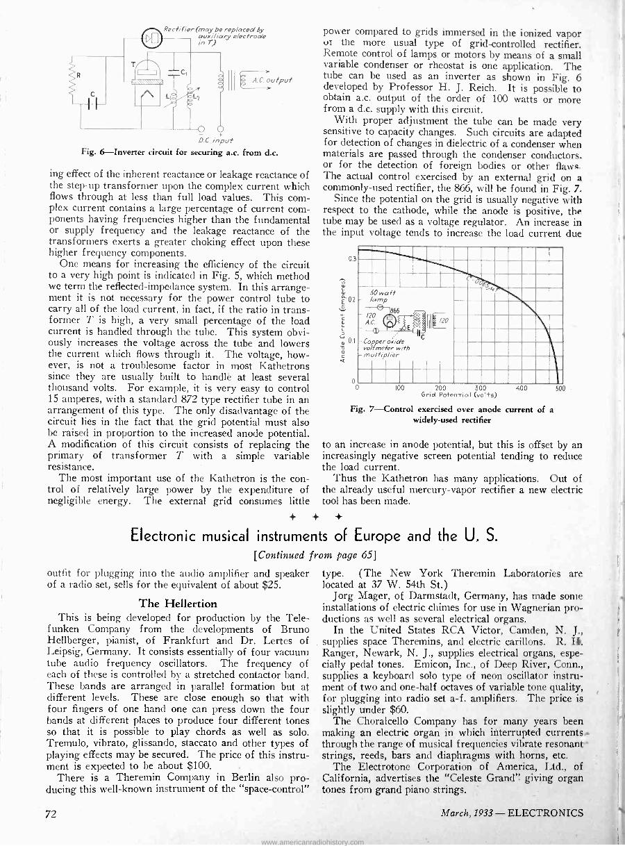
D . input Fig. 6-Inverter circuit for securing a.c. from d.c.
ing effect of the inherent reactance or leakage reactance of the step-up transformer upon the complex current which flows through at less than full load values. This com- plex current contains a large percentage of current com- ponents having frequencies higher than the fundamental or supply frequency and the leakage reactance of the transformers exerts a greater choking effect upon these higher frequency components.
One means for increasing the efficiency of the circuit to a very high point is indicated in Fig. 5, which method we term the reflected -impedance system. In this arrange- ment it is not necessary for the power control tube to carry all of the load current, in fact, if the ratio in trans- former T is high, a very small percentage of the load current is handled through the tube. This system obvi- ously increases the voltage across the tube and lowers the current which flows through it. The voltage, how- ever, is not a troublesome factor in most Kathetrons since they are usually built to handlë at least several thousand volts. For example, it is very easy to control 15 amperes, with a standard 872 type rectifier tube in an arrangement of this type. The only disadvantage of the circuit lies in the fact that the grid potential must also be raised in proportion to the increased anode potential. A modification of this circuit consists of replacing the primary of transformer T with a simple variable resistance.
The most important use of the Kathetron is the con- trol of relatively large power by the expenditure of negligible energy. The external grid consumes little
power compared to grids immersed in the ionized vapor ut the more usual type of grid -controlled rectifier. Remote control of lamps or motors by means of a small variable condenser or rheostat is one application. The tube can be used as an inverter as shown in Fig. 6 developed by Professor H. J. Reich. It is possible to obtain a.c. output of the order of 100 watts or more from a d.c. supply with this circuit.
With proper adjustment the tube can be made very sensitive to capacity changes. Such circuits are adapted for detection of changes in dielectric of a condenser when materials are passed through the condenser conductors. or for the detection of foreign bodies or other flaws - The actual control exercised by an external grid on a commonly -used rectifier, the 866, will be found in Fig. 7.
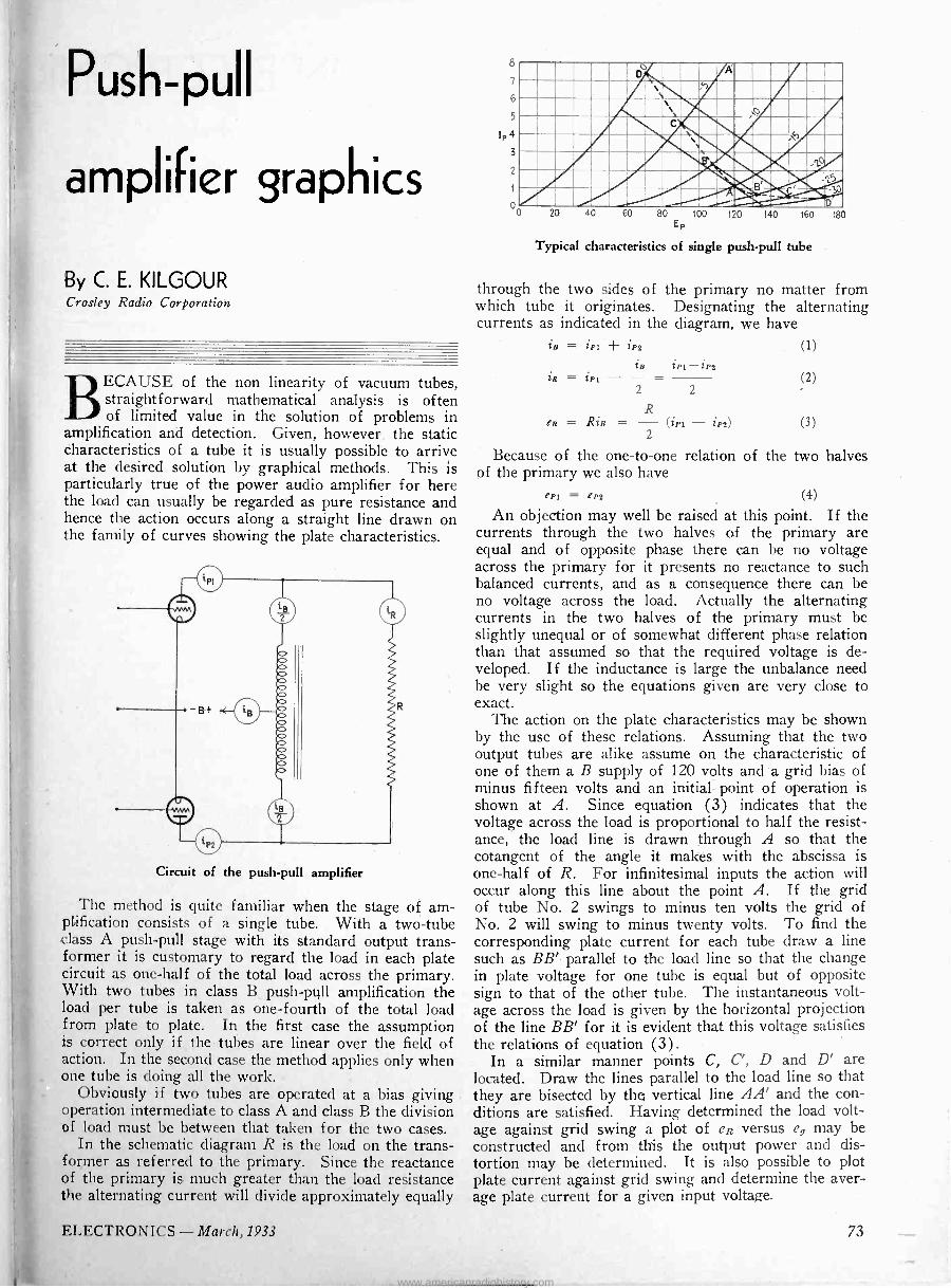
Since the potential on the grid is usually negative with respect to the cathode, while the anode is positive, the tube may be used as a voltage regulator. An increase in the input voltage tends to increase the load current due
0.3
o 0 100 200 300
Grid Potential (volts)
50 watt - lamp
-i
866 - 120 AC E.l
111ó /20
- voColtpermetero
-multiplier pxide
wit h C
400
Fig. 7-Control exercised over anode current of a widely -used rectifier
500
to an increase in anode potential, but this is offset by an increasingly negative screen potential tending to reduce the load current.
Thus the Kathetron has many applications. Out of the already useful mercury-vapor rectifier a new electric tool has been made.
+ +
Electronic musical instruments of Europe and the U. S.
[Continued from page 65]
outfit for plugging into the audio amplifier and speaker of a radio set, sells for the equivalent of about $25.
The Hellertion This is being developed for production by the Tele-
funken Company from the developments of Bruno Hellberger, pianist, of Frankfurt and Dr. Lertes of Leipsig, Germany. It consists essentially of four vacuum tube audio frequency oscillators. The frequency of each of these is controlled by a stretched contactor band. These bands are arranged in parallel formation but at different levels. These are close enough so that with four fingers of one hand one can press down the f our bands at different places to produce f our different tones so that it is possible to play chords as well as solo. Tremulo, vibrato, glissando, staccato and other types of playing effects may be secured. The price of this instru- ment is expected to be about $100.
There is a Theremin Company in Berlin also pro- ducing this well-known instrument of the "space -control"
type. (The New York Theremin Laboratories are located at 37 W. 54th St.)
Jorg Mager, of Darmstadt, Germany, has made some installations of electric chimes for use in Wagnerian pro- ductions as well as several electrical organs.
In the United States RCA Victor, Camden, N. J., supplies space Theremins, and electric carillons. R. Ranger, Newark, N. J., supplies electrical organs, espe- cially pedal tones. Emicon, Inc., of Deep River, Conn., supplies a keyboard solo type of neon oscillator instru- ment of two and one-half octaves of variable tone quality, for plugging into radio set a -f. amplifiers. The price is slightly under $60.
The Choralcello Company has for many years been making an electric organ in which interrupted currents through the range of musical frequencies vibrate resonant strings, reeds, bars and diaphragms with horns, etc.
The Electrotone Corporation of America, Ltd., of California, advertises the "Celeste Grand" giving organ tones from grand piano strings.
72 March, 1933 - ELECTRONICS
www.americanradiohistory.com
P5h-ll pu
amplifier graphics
By C. E. KILGOUR Crosley Radio Corporation
BECAUSE of the non linearity of vacuum tubes, straightforward mathematical analysis is often of limited value in the solution of problems in
amplification and detection. Given, however, the static characteristics of a tube it is usually possible to arrive at the desired solution by graphical methods. This is particularly true of the power audio amplifier for here the load can usually be regarded as pure resistance and hence the action occurs along a straight line drawn on the family of curves showing the plate characteristics.
Circuit of the push-pull amplifier
The method is quite familiar when the stage of am- plification consists of a single tube. With a two -tube class A push-pull stage with its standard output trans- former it is customary to regard the load in each plate circuit as one-half of the total load across the primary. With two tubes in class B push-pull amplification the load per tube is taken as one-fourth of the total load from plate to plate. In the first case the assumption is correct only if the tubes are linear over the field of action. In the second case the method applies only when one tube is doing all the work.
Obviously if two tubes are operated at a bias giving operation intermediate to class A and class B the division of load must be between that taken for the two cases.
In the schematic diagram R is the load on the trans- former as referred to the primary. Since the reactance of the primary is much greater than the load resistance the alternating current will divide approximately equally
20 40 60 80 100 120 140 Ep
160 180
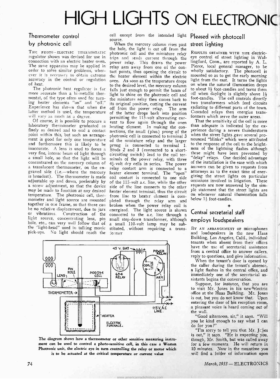
Typical characteristics of single push-pull tube
through the two sides of the primary no matter from which tube it originates. Designating the alternating currents as indicated in the diagram, we have
in = ¡Pi iP2
in iP1-iP2 (1)
iR = ¡PI (2) 2 2
R eR = Ris = (iPi - ip2) (3) -
2
Because of the one-to-one relation of the two halves of the primary we also have
ePl = eP2 (4)
An objection may well be raised at this point. If the currents through the two halves of the primary are equal and of opposite phase there can be no voltage across the primary for it presents no reactance to such balanced currents, and as a consequence there can be no voltage across the load. Actually the alternating currents in the two halves of the primary must be slightly unequal or of somewhat different phase relation than that assumed so that the required voltage is de- veloped. If the inductance is large the unbalance need be very slight so the equations given are very close to exact.
The action on the plate characteristics may be shown by the use of these relations. Assuming that the two output tubes are alike assume on the characteristic of one of them a B supply of 120 volts and -a grid bias of minus fifteen volts and an initial point of operation is shown at A. Since equation (3) indicates that the voltage across the load is proportional to half the resist- ance, the load line is drawn through A so that the cotangent of the angle it makes with the abscissa is one-half of R. For infinitesimal inputs the action will occur along this line about the point A. If the grid of tube No. 2 swings to minus ten volts the grid of No. 2 will swing to minus twenty volts. To find the corresponding plate current for each tube draw a line such as BB' parallel to the load line so that the change in plate voltage for one tube is equal but of opposite sign to that of the other tube. The instantaneous volt- age across the load is given by the horizontal projection of the line BB' for it is evident that this voltage satisfies the relations of equation (3).
In a similar manner points C, C', D and D' are located. Draw the lines parallel to the load line so that they are bisected by thq vertical line AA' and the con- ditions are satisfied. Having determined the load volt- age against grid swing a plot of eR versus eg may be constructed and from this the output power and dis- tortion may be determined. It is also possible to plot plate current against grid swing and determine the aver- age plate current for a given input voltage.
ELECTRONICS -March, 1933 73
www.americanradiohistory.com
HIGH LIGHTS ON ELECTRONIC Thermometer control by photronic cell
THE PHOTO - ELECTRIC THERMOSTATIC regulator shown was devised for use in connection with an electric heater oven. The same apparatus may be applied in order to solve similar problems, wher- ever it is necessary to obtain extreme accuracy in the control or regulation of heat.
The photronic heat regulator is far more accurate than a bi -metallic ther- mostat, of the type often used for turn- ing heater elements "on" and "off." Experience has shown that when the latter method is used, the temperature will vary as much as a degree.
Of course, it is possible to procure a lab6ratory thermometer graduated as finely as desired and to seal a contact point within this, but such an arrange- ment is good for only one temperature and furthermore this is likely to be inaccurate. A lens is used to focus a very fine, intense beam of light through a small hole, so that the light will be concentrated on the mercury column of a translucent thermometer, on the en- graved side (i.e.-where the mercury is broadest). The thermometer is made adjustable up and down, preferably by a screw adjustment, so that the device may be made to function at any desired temperature. The photronic cell, ther- mometer and light source are mounted together in one frame, so that there can be no relative displacement, due to jars or vibrations. Construction of the light source, concentrating lens, pin hole, etc., can very well follow that of the "light -head" used in talking movie pick-ups. No light should reach the
cell except from the intended light source.
When the mercury column rises past the hole, the light is cut off from the photronic cell and the miniature relay trips and sends current through the power relay. This draws the power relay arm away from one of the con- tact points, thus opening the circuit to the heater element within the electric oven. As soon as the temperature drops to the desired level, the mercury column falls just enough to permit the beam of light to shine on the photronic cell and the miniature relay then comes back to its original position, cutting the current off from the power relay. The arm of the latter drops back into position permitting the 115 -volt alternating cur- rent to flow again through the oven heating element. In making the con- nections, the small (plus) prong of the photronic cell is connected to terminal 3 of the miniature relay and the larger prong is connected to terminal 1. Studs 2 and 3 (connected to a short- circuiting switch) lead to the coil ter- minals of the power relay, with three 44 -volt dry cells in series. The power relay contact arm is connected to a heater element terminal. The "open" coil contact is connected to one side of the 115 -volt a.c. line, while the other side of the line connects to the other heater element terminal, thus the circuit from line to heater element is com- pleted through the relay arm and broken when the power relay coil is energized. The light source is shown connected to the a.c. line through a small step-down transformer, although a small 110 -volt lamp may be sub- stituted, . without requiring a trans- former
.QQQ.
'000'
45 v. BAT 1I1 10±
PIN HOLE
LENS' \ MOD 594
CELL
o___p` ÌÌ= THERMOMETER -3
HEATER
I,
634 RELAY
ELECTRIC FURNACE..
PO LAY
The diagram shows how a thermometer or other sensitive measuring instru- ment can be used to control a photo -sensitive cell, in this case a Weston Photronic unit, the electric eye in turn controlling the relay or motor which
is to be actuated at the critical temperature or current value
Pleased with photocell street lighting RESULTS OBTAINED WITH THE electric - eye control of street lighting in Wal- lingford, Conn., are reported by A. L. Pierce, local general manager, to be wholly satisfactory. The photocell is mounted so as to get the early morning light from the east. It turns the lights on when the natural illumination drops to about 14 foot-candles and turns them off when daylight is slightly above 14 foot-candles. The cell controls directly two transformers which feed circuits radiating to different parts of the town. Cascaded relays then energize trans- formers which serve the outer areas.
That the sensitivity of the cell is more than adequate is indicated by the ex- perience during a severe thunderstorm when the street lights gave several pro- nounced "blinks" which were attributed to the response of the cell to the bright- ness of the lightning flashes although these might have been prevented by "delay" relays. One decided advantage of the installation is the ease with which answers can be given to requests from attorneys as to the exact time of ener- gizing the street lights on particular occasions involved in litigation. These requests are now answered by the sim- ple statement that the street lights are on whenever natural illumination falls below 14 foot-candles.
Central secretarial staff
employs loudspeakers
BY AN ARRANGEMENT OF microphones and loudspeakers in the new Haas Building, Los Angeles, Calif., individual tenants when absent from their offices have the use of secretarial assistance from a central office to answer callers, reply to questions, and give information.
When the tenant's door is opened by the caller during the tenant's absence, a light flashes in the central office, and immediately one of the secretarial as- sistants begins the conversation.
Suppose, for instance, that you are to visit Mr. Jones in his new electric office at the Haas Building. Mr. Jones is out, but you do not know that. Upon entering the door of his reception room, a pleasant voice is heard coming out of the wall.
"Good afternoon, sir," it says. "Will you be kind enough to say what I can do for you ?"
"I'm sorry to tell you that Mr. Jcnes is out," it says. "He is expecting you, though, Mr. Smith, but was called away for a few moments. He will return in 10 minutes. Now in the meantime you will find a folder of information upon
74 March,1933 - ELECTRONICS
www.americanradiohistory.com
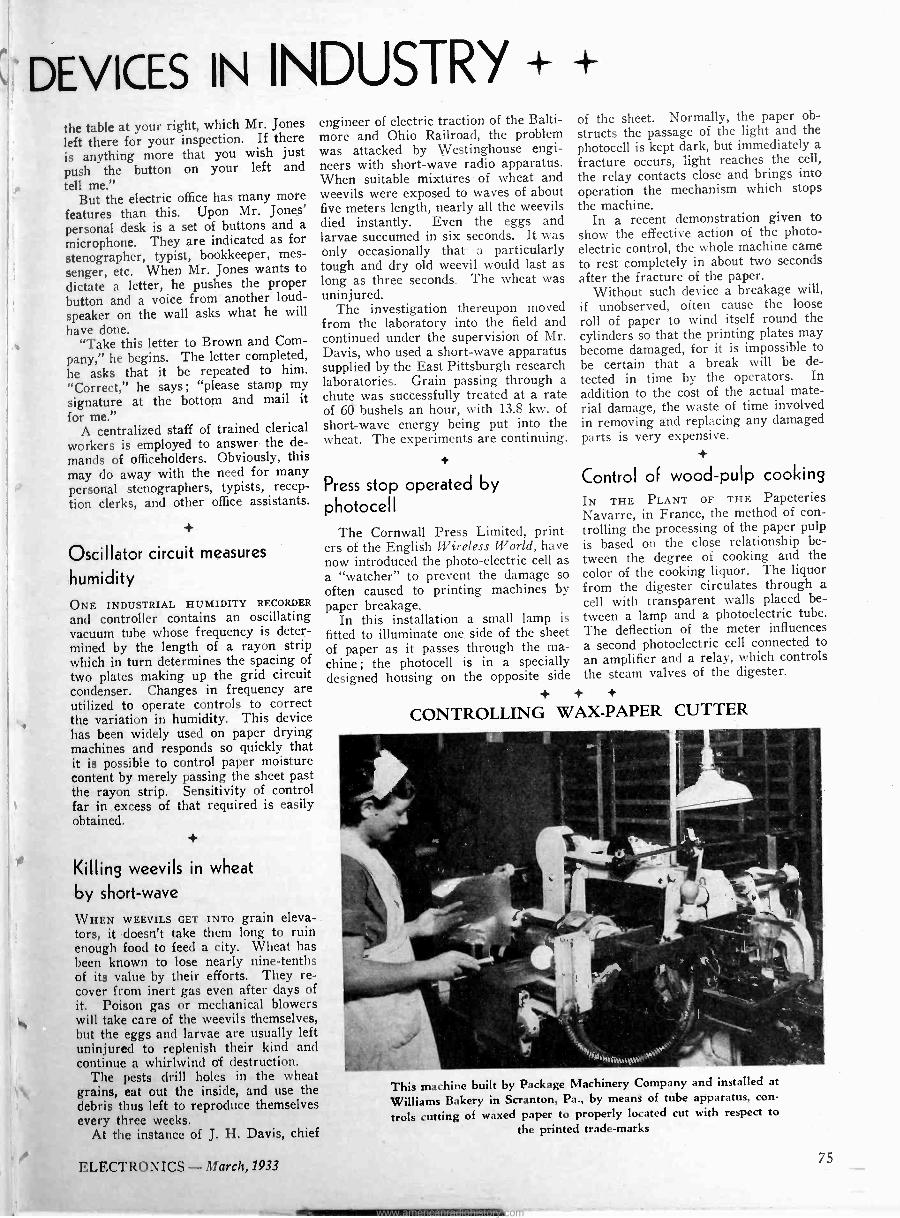
DEVICES IN INDUSTRY + + the table at your right, which Mr. Jones left there for your inspection. If there is anything more that you wish just push the button on your left and tell me."
But the electric office has many more features than this. Upon Mr. Jones' personal desk is a set of buttons and a microphone. They are indicated as for stenographer, typist, bookkeeper, mes- senger, etc. When Mr. Jones wants to dictate a letter, he pushes the proper button and a voice from another loud- speaker on the wall asks what he will have done.
"Take this letter to Brown and Com- pany," he begins. The letter completed, he asks that it be repeated to him. "Correct," he says; "please stamp my signature at the bottom and mail it for me."
A centralized staff of trained clerical workers is employed to answer the de- mands of officeholders. Obviously, this may do away with the need for many personal stenographers, typists, recep- tion clerks, and other office assistants.
Oscillator circuit measures
humidity ONE INDUSTRIAL HUMIDITY RECORDER
and controller contains an oscillating vacuum tube whose frequency is deter- mined by the length of a rayon strip which in turn determines the spacing of two plates making up the grid circuit condenser. Changes in frequency are utilized to operate controls to correct the variation in humidity. This device has been widely used on paper drying machines and responds so quickly that it is possible to control paper moisture content by merely passing the sheet past the rayon strip. Sensitivity of control far in excess of that required is easily obtained.
engineer of electric traction of the Balti- more and Ohio Railroad, the problem was attacked by Westinghouse engi- neers with short-wave radio apparatus. When suitable mixtures of wheat and weevils were exposed to waves of about five meters length, nearly all the weevils died instantly. Even the eggs and larvae succumed in six seconds. It was only occasionally that a particularly tough and dry old weevil would last as long as three seconds. The wheat was uninjured.
The investigation thereupon moved from the laboratory into the field and continued under the supervision of Mr. Davis, who used a short-wave apparatus supplied by the East Pittsburgh research laboratories. Grain passing through a chute was successfully treated at a rate of 60 bushels an hour, with 13.8 kw. of short-wave energy being put into the wheat. The experiments are continuing.
Killing weevils in wheat
by short-wave
WHEN WEEVILS GET INTO grain eleva- tors, it doesn't take them long to ruin enough food to feed a city. Wheat has been known to lose nearly nine -tenths of its value by their efforts. They re- cover from inert gas even after clays of it. Poison gas or mechanical blowers will take care of the weevils themselves, but the eggs and larvae are usually left uninjured to replenish their kind and continue a whirlwind of destruction.
The pests drill holes in the wheat grains, eat out the inside, and use the debris thus left to reproduce themselves every three weeks.
At the instance of J. H. Davis, chief
Press stop operated by photocell
The Cornwall Press Limited, print- ers of the English Wireless World, have now introduced the photo -electric cell as a "watcher" to prevent the damage so often caused to printing machines by paper breakage.
In this installation a small lamp is fitted to illuminate one side of the sheet of paper as it passes through the ma- chine; the photocell is in a specially d i d housin on the opposite side esgne g
+ + +
CONTROLLING WAX -PAPER
of the sheet. Normally, the paper ob- structs the passage of the light and the photocell is kept dark, but immediately a fracture occurs, light reaches the cell, the relay contacts close and brings into operation the mechanism which stops the machine.
In a recent demonstration given to show the effective action of the photo- electric control, the whole machine came to rest completely in about two seconds after the fracture of the paper.
Without such device a breakage will, if unobserved, often cause the loose roll of paper to wind itself round the cylinders so that the printing plates may become damaged, for it is impossible to be certain that a break will be de- tected in time by the operators. In addition to the cost of the actual mate- rial damage, the waste of time involved in removing and replacing any damaged parts is very expensive.
Control of wood -pulp cooking IN THE PLANT OF THE Papeteries Navarre, in France, the method of con- trolling the processing of the paper pulp is based on the close relationship be- tween the degree of cooking and the color of the cooking liquor. The liquor from the digester circulates through a cell with transparent walls placed be- tween a lamp and a photoelectric tube. The deflection of the meter influences a second photoelectric cell connected to an amplifier and a relay, which controls the steam valves of the digester.
CUTTER
This machine built by Package Machinery Company and installed at
Williams Bakery in Scranton, Pa., by means of tube apparatus, con-
trols cutting of waxed paper to properly located cut with respect to the printed trade -marks
1?LECTRONICS -March,1933 75
www.americanradiohistory.com
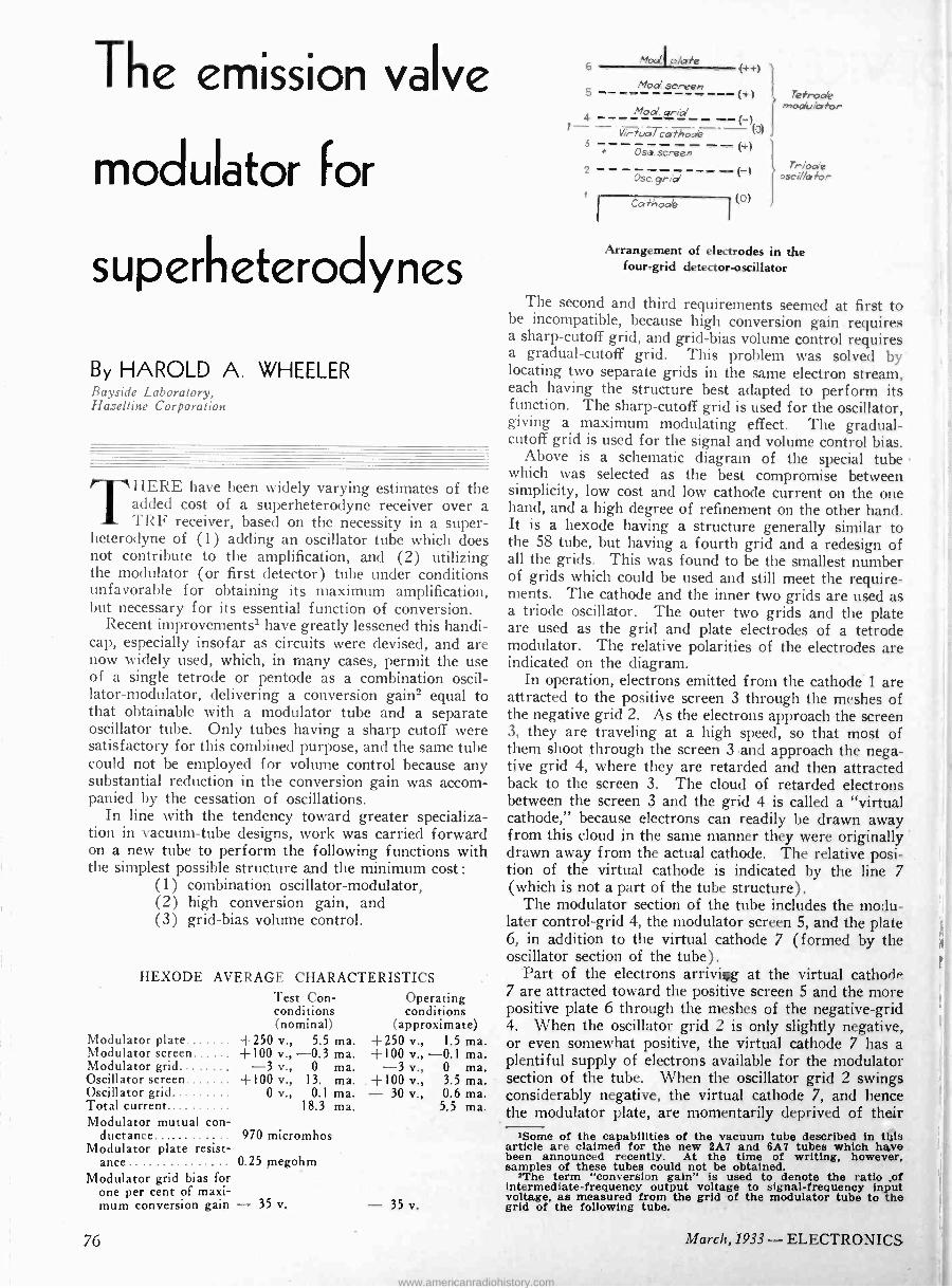
The emission valve
modulator For
superheterodynes
By HAROLD A. WHEELER Bayside Laboratory, Hazeltine Corporation
THERE have been widely varying estimates of the added cost of a superheterodyne receiver over a TRF receiver, based on the necessity in a super-
heterodyne of (1) adding an oscillator tube which does not contribute to the amplification, and (2) utilizing the modulator (or first detector) tube under conditions unfavorable for obtaining its maximum amplification, but necessary for its essential function of conversion.
Recent improvements' have greatly lessened this handi- cap, especially insofar as circuits were devised, and are now widely used, which, in many cases, permit the use of a single tetrode or pentode as a combination oscil- lator -modulator, delivering a conversion gain2 equal to that obtainable with a modulator tube and a separate oscillator tube. Only tubes having a sharp cutoff were satisfactory for this combined purpose, and the same tube could not be employed for volume control because any substantial reduction in the conversion gain was accom- panied by the cessation of oscillations.
In line with the tendency toward greater specializa- tion in vacuum -tube designs, work was carried forward on a new tube to perform the following functions with the simplest possible structure and the minimum cost :
(1) combination oscillator -modulator, (2) high conversion gain, and (3) grid -bias volume control.
HEXODE AVERAGE CHARACTERISTICS
Modulator plate .. Modulator screen......
Test Con - conditions (nominal)
+250 v., 5.5 ma. +100 v., -0.3 ma.
Operating conditions
(approximate) +250 v., 1.5 ma. +100 v., -0.1 ma.
Modulator grid........ -3 v., 0 ma. -3 v., 0 ma. Oscillator screen +100 v., 13. ma. +100 v., 3.5 ma. Oscillator grid......... Total current.
0 v., 0.1 ma. 18.3 ma.
- 30 v., 0.6 ma. 5.5 ma.
Modulator mutual con- ductance...... 970 micromhos
Modulator plate resist- ance 0.25 megohm
Modulator grid bias for one per cent of maxi- mum conversion gain - 35 v. - 35 v.
6 Mod.' p/ate
(++)
Mod screen --- (+) retrode mode/ator
1- - itexa/ cothode _(-)
(c))
3 ' Ose. screen (4.1
Osc. grid Triode
osci//a tor
Cathoa'e (01
Arrangement of electrodes in the four -grid detector -oscillator
The second and third requirements seemed at first to be incompatible, because high conversion gain requires a sharp -cutoff grid, and grid -bias volume control requires a gradual -cutoff grid. This problem was solved by locating two separate grids in the same electron stream, each having the structure best adapted to perform its function. The sharp -cutoff grid is used for the oscillator, giving a maximum modulating effect. The gradual - cutoff grid is used for the signal and volume control bias.
Above is a schematic diagram of the special tube which was selected as the best compromise between simplicity, low cost and low cathode current on the one hand, and a high degree of refinement on the other hand. It is a hexode having a structure generally similar to the 58 tube, but having a fourth grid and a redesign of all the grids. This was found to be the smallest number of grids which could be used and still meet the require- ments. The cathode and the inner two grids are used as a triode oscillator. The outer two grids and the plate are used as the grid and plate electrodes of a tetrode modulator. The relative polarities of the electrodes are indicated on the diagram.
In operation, electrons emitted from the cathode 1 are attracted to the positive screen 3 through the meshes of the negative grid 2. As the electrons approach the screen 3, they are traveling at a high speed, so that most of them shoot through the screen 3 and approach the nega- tive grid 4, where they are retarded and then attracted back to the screen 3. The cloud of retarded electrons between the screen 3 and the grid 4 is called a "virtual cathode," because electrons can readily be drawn away from this cloud in the same manner they were originally drawn away from the actual cathode. The relative posi- tion of thé virtual cathode is indicated by the line 7 (which is not a part of the tube structure).
The modulator section of the tube includes the modu- later control -grid 4, the modulator screen 5, and the plate 6, in addition to the virtual cathode 7 (formed by the oscillator section of the tube).
Part of the electrons arriviig at the virtual cathode 7 are attracted toward the positive screen 5 and the more positive plate 6 through the meshes of the negative -grid 4. When the oscillator grid 2 is only slightly negative, or even somewhat positive, the virtual cathode 7 has a plentiful supply of electrons available for the modulator section of the tube. When the oscillator grid 2 swings considerably negative, the virtual cathode 7, and hence the modulator plate, are momentarily deprived of their
'Some of the capabilities of the vacuum tube described in tills article are claimed for the new 2A7 and 6A7 tubes which hive been announced recently. At the time of writing, however, samples of these tubes could not be obtained.
'The term "conversion gain" is used to denote the ratio of intermediate -frequency output voltage to signal -frequency input voltage, as measured from the grid of the modulator tube to the grid of the following tube.
76 March, 1933 - ELECTRONICS
www.americanradiohistory.com
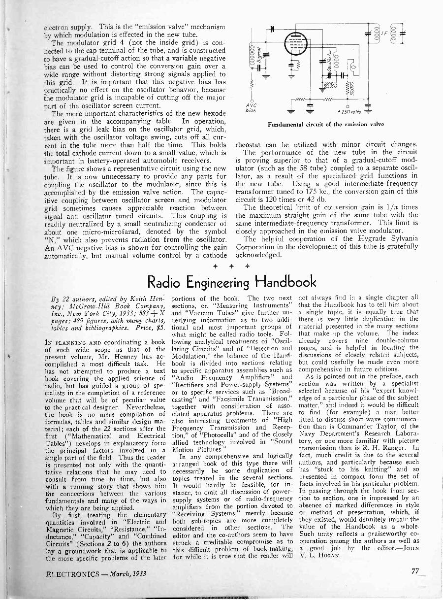
electron supply. This is the "emission valve" mechanism by which modulation is effected in the new tube.
The modulator grid 4 (not the inside grid) is con- nected to the cap terminal of the tube, and is constructed to have a gradual -cutoff action so that a variable negative bias can be used to control the conversion gain over a wide range without distorting strong signals applied to this grid. It is important that this negative bias has practically no effect on the oscillator behavior, because the modulator grid is incapable of cutting off the major part of the oscillator screen current.
The more important characteristics of the new hexode are given in the accompanying table. In operation, there is a grid leak bias on the oscillator grid, which, taken with the oscillator voltage swing, cuts off all cur- rent in the tube more than half the time. This holds the total cathode current down to a small value, which is important in battery -operated automobile receivers.
The figure shows a representative circuit using the new tube. It is now unnecessary to provide any parts for coupling the oscillator to the modulator, since this is accomplished by the emission valve action. The capac- itive coupling between oscillator screen and modulator grid sometimes causes appreciable reaction between signal and oscillator tuned circuits. This coupling is readily neutralized by a small neutralizing condenser of about one micro-microfarad, denoted by the symbol "N," which also prevents radiation from the oscillator. An AVC negative bias is shown for controlling the gain automatically, but manual volume control by a cathode
+ +
IF
Fundamental circuit of the emission valve
rheostat can be utilized with minor circuit changes. The performance of the new tube in the circuit
is proving superior to that of a gradual -cutoff mod- ulator (such as the 58 tube) coupled to a separate oscil- lator, as a result of the specialized grid functions in the new tube. Using a good intermediate -frequency transformer tuned to 175 kc., the conversion gain of this circuit is 120 times or 42 db.
The theoretical limit of conversion gain is 1/n times the maximum straight gain of the same tube with the same intermediate -frequency transformer. This limit is closely approached in the emission valve modulator.
The helpful cooperation of the Hygrade Sylvania Corporation in the development of this tube is gratefully acknowledged.
Radio Engineering Handbook By 22 authors, edited by Keith Hen: ney; McGraw-Hill Book Company, Inc., New York City, 1933; 583 + X pages; 489 figures, with many charts, tables and bibliographies. Price, $5.
IN PLANNING AND coordinating a book of such wide scope as that of the present volume, Mr. Henney has ac- complished a most difficult task. He has not attempted to produce a text book covering the applied science of radio, but has guided a group of spe- cialists in the completion of a reference volume that will be of peculiar value to the practical designer. Nevertheless, the book is no mere compilation of formulas, tables and similar design ma- terial ; each of the 22 sections after the first ("Mathematical and Electrical Tables") develops in explanatory form the principal factors involved in, a single part of the field. Thus the reader is presented not only with the quanti- tative relations that he may need to consult from time to time, but also with a running story that shows him the connections between the various fundamentals and many of the ways in which they are being applied.
By first treating the elementary quantities involved in "Electric and Magnetic Circuits," "Resistance," "In- ductance," "Capacity" and "Combined Circuits" (Sections 2 to 6) the authors lay a groundwork that is applicable to the more specific problems of the later
portions of the book. The two next sections, on "Measuring Instruments" and "Vacuum Tubes" give further un- derlying information as to two addi- tional and most important groups of what might be called radio tools. Fol- lowing analytical treatments of "Oscil- lating Circuits" and of "Detection and Modulation," the balance of the Hand- book is divided into sections relating to specific apparatus assemblies such as "Audio Frequency Amplifiers" and "Rectifiers and Power -supply Systems" or to specific services such as "Broad- casting" and "Facsimile Transmission," together with consideration of asso- ciated apparatus problems. There are also interesting treatments of "High Frequency Transmission and Recep- tion," of "Photocells" and of the closely allied technology involved in "Sound Motion Pictures."
In any comprehensive and logically arranged book of this type there will necessarily be some duplication of topics treated in the several sections. It would hardly be feasible, for in- stance, to omit all discussion of power - supply systems or of radio -frequency amplifiers from the portion devoted to "Receiving Systems," merely because both sub -topics are more completely considered in other sections. The editor and the co-authors seem to have struck a creditable compromise as to this difficult problem of book -making, for while it is true that the reader will
not always find in a single chapter all that the Handbook has to tell him about a single topic, it is equally true that there is very little duplication in the material presented in the many sections that make up the volume. The index already covers nine double -column pages, and is helpful in locating the discussions of closely related subjects, but could -usefully be made even more comprehensive in future editions.
As is pointed out in the preface, each section was written by a specialist selected because of his "expert knowl- edge of a particular phase of the subject matter," and indeed it would be difficult to find (for example) a man better fitted to discuss short-wave communica- tion than is Commander Taylor, of the Navy Department's Research Labora- tory, or one more familiar with picture transmission than is R. H. Ranger. In fact, much credit is due to the several authors, and particularly because each has "stuck to his knitting" and so presented in compact form the set of facts involved in his particular problem. In passing through the book from sec- tion to section, one is impressed by an absence of marked differences in style or method of presentation, which, if they existed, would definitely impair the value of the Handbook as a whole. Such unity reflects a praiseworthy co- operation among the authors as well as a good job by the editor.-JOHN V. L. HOGAN.
ELECTRONICS - March, 1933 77
www.americanradiohistory.com
electronics
Volume VI
McGraw-Hill Publishing Company, Inc. 330 West 42d Street
New York City
O. H. CALDWELL, Editor
-MARCH, 1933- Number 3
Time to turn back to quality IF a program for stabilization can be carried out
by the receiving -set manufacturers, its good effects will be felt all along the line to their parts suppliers as well. A move for higher prices on the part of the set makers would automatically reduce the pressure on the parts makers for lower prices. Instead there would be a demand for bet- ter -quality parts to bring better set values, in turn giving the public solid values and higher quality and so fully justifying a higher price level.
Parts prices have been pushed down to an un- sound bottom, where operating quality and dura- bility have been seriously impaired. The public interest now lies in stabilizing back to quality.
Designing radios for
increased sales
UNDOUBTEDLY the industrial designer is destined to play a more active part in the
radio set field than he has in the past. As results of designers' work in increasing sales is demon- strated in other fields, the call will come for more such aid to radio.
But if the designer is to be consulted, he should he called in at the beginning of the job. After the tools have been made, and the chassis form is fixed, the stylist can make only minor sugges- tions regarding design-changing details or adding decoration and color.
The full benefit of the artist's help can be realized only if he is consulted from the very beginning and urged to co-operate fully with the sales and production departments.
Binaural sound
reproduction soon
IT will not be long now, before the subject of
binaural or "stereoscopic" sound reproduction will come prominently to the attention of the pub- lic and the sound industry. With two sound- tracks or two reproducing circuits, differing in relative intensity as the actors or sources of sound move about on the stage or screen, the listener gets a new sense of perspective. He can, in effect, actually "hear the band march across the field of view," or he can sense the back -and -forth dialog of the actors on opposite sides of the screen. Such binaural hearing gives a new sense of reality and perspective to the picture or play, in place of the flat effect of a single bank of speakers.
Each improvement in realism in the past has meant increased popularity and increased earnings for the industry. Evidently another forward step, both technically and economically, is soon in pros- pect for sound reproduction.
Exports fall; some countries increase purchases
EXPORTS of radio sets from the United States during 1932 were $13,312,136, a
sharp drop-off from the $22,000,000 exports of the preceding year. Yet to forty-three out of the 103 countries to which export sales were made, increases in purchases were registered. These cus- tomers whose buying of radio increased, included Belgium, Irish Free State, Holland, Norway, Yugoslavia, Panama, Haiti, Bolivia, Colombia, China, Paraguay, Turkey, Australia, and Mo- rocco.
Loss of $3,000,000 exports to Canada can be ascribed largely to the new Dominion law requir- ing a percentage of Canadian -made parts in Canadian sets. The quota system in France limited our purchases there. Italy has imposed higher radio -set duties; this limited sales. Bri- tain's departure from the gold standard made purchases in our market too expensive.
Increased broadcasting activity in China re- sulted in growing imports of American sets. Ar- gentina is now the largest customer for American radios, supplanting Canada, which has dropped to second place.
78 March, 1933 - ELECTRONICS
www.americanradiohistory.com
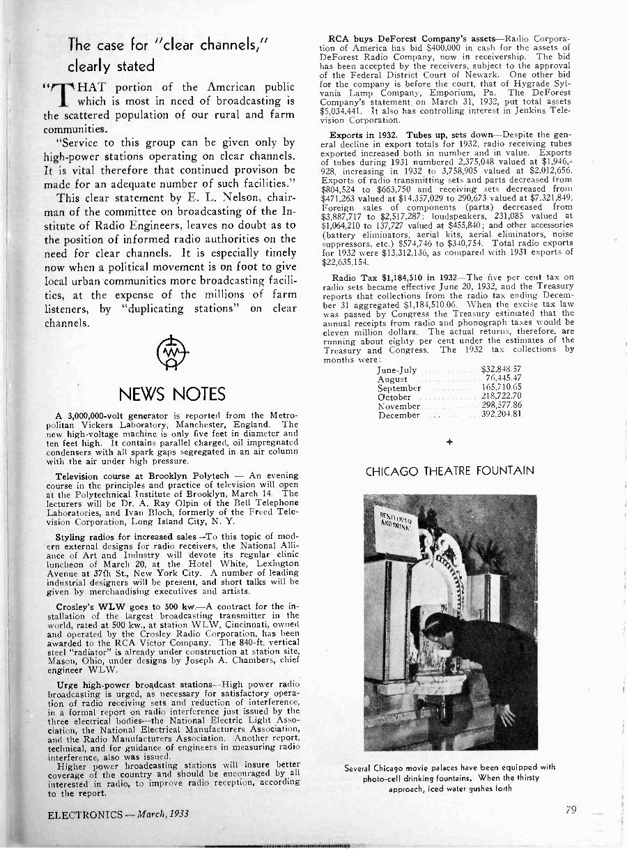
The case for "clear channels,"
clearly stated
d
drfHAT portion of the American public 1 which is most in need of broadcasting is
the scattered population of our rural and farm communities.
"Service to this group can be given only by high -power stations operating on clear channels. It is vital therefore that continued provison be made for an adequate number of such facilities."
This clear statement by E. L. Nelson, chair- man of the committee on broadcasting of the In- stitute of Radio Engineers, leaves no doubt as to the position of informed radio authorities on the need for clear channels. It is especially timely now when a political movement is on foot to give local urban communities more broadcasting facili- ties, at the expense of the millions of farm listeners, by "duplicating stations" on clear channels.
(e - NEWS NOTES
A 3,000,000 -volt generator is reported from the Metro- politan Vickers Laboratory, Manchester, England. The new high -voltage machine is only five feet in diameter and ten feet high. It contains parallel charged, oil impregnated condensers with all spark gaps segregated in an air column with the air under high pressure.
Television course at Brooklyn Polytech - An evening course in the principles and practice of television will open at the Polytechnical Institute of Brooklyn, March 14. The lecturers will be Dr. A. Ray Olpin of the Bell Telephone Laboratories, and Ivan Bloch, formerly of the Freed Tele- vision Corporation, Long Island City, N. Y.
Styling radios for increased sales-To ern external designs for radio receivers, ance of Art and Industry will devote luncheon of March 20, at the Hotel Avenue at 37th St., New York City. A industrial designers will be present, and given by merchandising executives and
this topic of mod - the National Alli - its regular clinic
White, Lexington number of leading short talks will be artists.
Crosley's WLW goes to 500 kw.-A contract for the in- stallation of the largest broadcasting transmitter in the world, rated at 500 kw., at station WLW, Cincinnati, owned and operated by the Crosley Radio Corporation, has been awarded to the RCA Victor Company. The 840 -ft. vertical steel "radiator" is already under construction at station site, Mason, Ohio, under designs by Joseph A. Chambers, chief engineer WLW.
Urge high -power broadcast stations-High power radio broadcasting is urged, as necessary for satisfactory opera- tion of radio receiving sets and reduction of interference, in a formal report on radio interference just issued by the three electrical bodies-the National Electric Light Asso- ciation, the National Electrical Manufacturers Association, and the Radio Manufacturers Association. Another report, technical, and for guidance of engineers in measuring radio interference, also was issued.
Higher power broadcasting stations will insure better coverage of the country and should be encouraged by all interested in radio, to improve radio reception, according to the report.
RCA buys DeForest Company's assets-Radio Corpora- tion of America has bid $400,000 in cash for the assets of DeForest Radio Company, now in receivership. The bid has been accepted by the receivers, subject to the approval of the Federal District Court of Newark. One other bid for the company is before the court, that of Hygrade Syl- vania Lamp Company, Emporium, Pa. The DeForest Company's statement_ on March 31, 1932, put total assets $5,034,441. It also has controlling interest in Jenkins Tele- vision Corporation.
Exports in 1932. Tubes up, sets down-Despite the gen- eral decline in export totals for 1932, radio receiving tubes exported increased both in number and in value. Exports of tubes during 1931 numbered 2,375,048 valued at $1,946,- 928, increasing in 1932 to 3,758,905 valued at $2,012,656. Exports of radio transmitting sets and parts decreased from $804,524 to $663,750 and receiving sets decreased from $471,263 valued. at $14,357,029 to 290,673 valued at $7,321,849. Foreign sales of components (parts) decreased from $3,887,717 to $2,517,287; loudspeakers, 231,085 valued at $1,064,210 to 137,727 valued at $455,840; and other accessories (battery eliminators, aerial kits, aerial eliminators, noise suppressors, etc.) $574,746 to $340,754. Total radio exports for 1932 were $13,312,136, as compared with 1931 exports of $22,635,154.
Radio Tax $1,184,510 in 1932-The five per cent tax on radio sets became effective June 20, 1932, and the Treasury reports that collections from the radio tax ending Decem- ber 31 aggregated $1,184,510.06. When the excise tax law was passed by Congress the Treasury estimated that -the annual receipts from radio and phonograph taxes would be eleven million dollars. The actual returns, therefore, are running about eighty per cent under the estimates of the Treasury and Congress. The 1932 tax collections by months were:
June -July $32,848.57 August 76,445.47 September 165,710.65 October 218,722.70 November 298,577.86 December 392,204.81
CHICAGO THEATRE FOUNTAIN
Several Chicago movie palaces have been equipped with
photo -cell drinking fountains. When the thirsty
approach, iced water gushes forth
ELECTRONICS - March, 1933 79
www.americanradiohistory.com
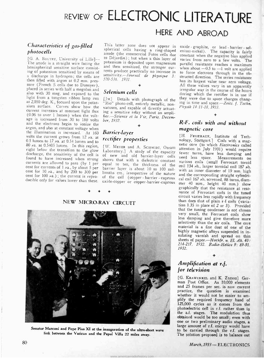
REVIEW OF ELECTRONIC LITERATURE HERE AND ABROAD
Characteristics of gas -filled photocells [G. A. BOUTRY, University of Lille]- The anode is a straight wire facing the hemispherical sensitive surface consist- ing of potassium sensitized by means of a discharge in hydrogen; the cells are then filled with argon at 0.2 mm. pres- sure (French S cells due to Dunoyer), placed in series with half a megohm and also with 30 meg, and exposed to the light from a tungsten ribbon lamp run at 2,050 deg. K., focused upon the potas- sium surface. Curves show how the current increases at constant light flux (0.06 to over 1 lumen) when the volt- age is increased from 30 to 180 volts and the electrons begin to ionize the argon, and also at constant voltage when the illumination is increased. At 160 volts the current grows from 12 µa. at 0.5 lumen to 17 µa. at 0.54 lumen and to 80 µa. at 0.5405 lumen. In this region, right below the transition to the glow discharge, the sensitivity of the cell is found to have increased when strong currents are allowed to pass (by 1 per cent for currents of 1 sa., by about 5 per cent for 10 µa., and by 200 to 300 per cent for 100 µa.) ; the current is repro- ducible only for values lower than these.
This latter zone does not appear in spherical cells having a ring -shaped anode (the commercial Fotos cells due to Déjardin) ; but when a thin layer of potassium is deposited upon magnesium and then sensitized, the stronger cur- rents produce practically no increase in sensitivity.-Journal de physique 3: 520-536. 1931.
Selenium cells [JM] Details with photograph of the "Rio" photo -cell, entirely metallic, non - vacuum, and capable of directly actuat- ing a sensitive relay without an ampli- fier.-Science et la Vie, Paris, Decem- ber, 1932.
Barrier -layer rectifier properties [W. MEYER and A. SCHMIDT, Osram Laboratory.] A study of the capacity of new and old barrier -layer cells shows that with a dielectric constant equal to ten, the thickness of the barrier layer is about 10 to 100 mil- lionths cm., irrespective of the nature of the cell (copper - barrier - cuprous oxide -copper or copper -barrier -cuprous
+ + +
NEW MICRO -RAY CIRCUIT
Senator Marconi and Pope Pius XI at the inauguration of the ultra -short wave link between the Vatican and the Papal Villa 22 miles away.
oxide - graphite, or lead - barrier - sel- enium -nickel). The capacity is fairly constant when the negative bias applied varies from zero to a few volts. The parallel resistance reaches a maximum when about -0.5 to -1 volt are applied to force electrons through in the ob- structed direction. The series resistance has its largest value near zero voltage. All these values vary in an apparently irregular way in the course of the hours during which the rectifier is in use if they were due to space charges chang- ing in time and space.-Zeits. f. Techn. Physik 14:11-18, 1933.
+
R -F. coils with and without magnetic core [H. FRUEHAUF, Institute of Tech- nology, Stuttgart.] Coils with a mag- netic core (to which Electronics called attention in July 1931) would require fewer turns, have less damping and need less space. Measurements on various coils (small Ferrocart toroid coil 134 µh., larger toroidal coil 187 µh. with an inner diameter of 19 mm. high and the corresponding straight cylindri- cal coil 167 µh, screened, 88 turns, diam- eter 40 mm., height 40 mm.) show graphically that the resistance at reso- nance of Ferrocart coils in the tuned circuit varies less rapidly with frequency than does that of plain r -f coils (varia- tion 1.35 in place of 2 or 3) . Provided that the tuning condenser is not chosen very small, the Ferrocart coils show less damping and give therefore more selectivity than the air coils. The core material is a fine dust of one of the highly magnetic alloys suspended in in- sulating varnish and spread on thin sheets of paper. Hoch f r. u. El. Ak. 40: 214-217. 1932. Radio -Helios 9: 89-91. 1932.
+
Amplification at r.f. for television [G. KRAWINKEL and K. ZIEBIG] Ger- man Post Office. As 10,000 elements and 25 frames per sec. is now current practice, the question is examined whether it would not be easier to am- plify the required frequency band of 125,000 cycles as it comes from the photoelectric cell in r.f. rather than in the a.f. stages. The modulation thus obtained would be too small ; even with one or two preliminary audio stages, a large amount of r.f. energy would have to be carried through the r.f. stages. The solution proposed is to balance out
80 March, 1933 - ELECTRONICS
www.americanradiohistory.com
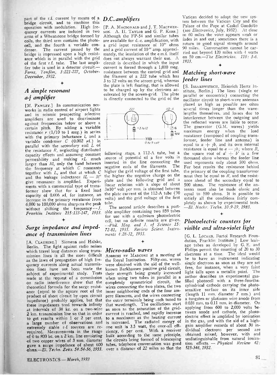
part of the r.f. current by means of a bridge circuit, and to combine this operation with modulation. High fre- quency currents are induced in two arms of a Wheatstone bridge formed by coils, the third arm contains the photo- cell, and the fourth a veriable con- denser. The current passed by the bridge is impressed upon a high resist- ance which is in parallel with the grid of the first r.f. tube. The last ampli- fier tube is used in a detector circuit.- Ferns, Tonfilm, 3:221-227, October - December, 1932.
A simple resonant a -f amplifier [M. PAWLEY.] In communication net- works in radio control of airport lights and in seismic prospecting selective amplifiers are used to discriminate against frequencies below or above a certain pitch. By adding a variable resistance r (1/10 to 1 meg.) in series with the primary inductance 1, and a variable condenser C (0.002 tf.) in parallel with the secondary coil L of the resistance R, neglecting distributed capacity effects and assuming constant permeability and making rL much larger than Rl, only the band between the frequency at which C resonants together with L, and that at which C and the leakage inductance lL - M' give resonance is amplified. Experi- ments with a commercial type of trans- former show that for a fixed load capacity of 0.006 µf, for instance, an increase in the primary resistance from 6,000 to 100,000 ohms sharpens the peak without shifting the frequency - J. Franklin Institute 215:133-147, 1933.
Surge impedance and imped- ance of transmission lines
[A. CLAUSING.] Siemens and Halske, Berlin. The fight against radio noises which travel long distances along trans- mission lines is all the more difficult as the laws of propagation of high fre- quency currents along actual transmis- sion lines have not been made the subject of experimental study. Tests made at the request of a commission ,on radio interference show that the theoretical formula for the surge resist- ance (equal to the square root of the product of short circuit by open circuit impedance) probably applies, but that these impedances tend towards infinity at intervals of 38 kc. on a two -wire 2 kin. transmission line so that in order to get results within 1 or 2 per cent, a large number of observations and extremely stable r -f sources are re - required. Measurements in the range of 0 to 800 kc. on a 2 km. line consisting .of two copper wires of 3 mm. diameter gave a surge impedance of about 600 .ohms.-El. Techn. Zeits. 54:54-56, 1933.
D.C. amplifiers [P. A. MACDONALD and J. T. MACPHER- SON. A. H. TAYLOR and G. P. KERR.] Although the FP -54 and similar tubes are available for d. -c. amplification, with a grid input resistance of 1018 ohms and a grid current of 10-" amp. approxi- mately, the insulation of the e.m.f. itself does not always warrant their use. A circuit is described in which the input current is forced through a 1,000 meg. resistance between the control grid and the filament of a 222 tube which has 3 to 12 volts on the screen grid, whereas the plate is left floating, that is allowed to be charged up by the electrons ac- celerated by the screen -grid. The plate is directly connected to the grid of the
222
0 to 9 volt
u2 -a
following stage, a 112-A tube, but a source of potential of a few volts is inserted in the line connecting the negative ends of the filaments. The higher the grid voltage of the first tube, the higher the negative charge on the plate and the following grid and a linear relation with a slope of about 3x10⁻⁴ volt per mm. is obtained between the plate current of the 112-A tube (90 volts) and thè grid voltage of the first tube.
The second article describes a port- able amplifier containing two 859 tubes for use with a cadmium photoelectric cell, but no definite results are given. -Phil. Mag. and J. of Science 15: 72-81, 1933. Review Scient. Instru- ments 4:28-32, 1933.
+
Micro -radio waves ADDRESS BY MARCONI at a meeting of
the Royal Institution. Fifty -cm. waves were obtained with the aid of the well- known Barkhausen positive grid circuit, their strength being greatly increased when using two tubes in parallel in a completely symmetrical circuit, the wires connecting the two plates, the two inner neighboring ends of the four am- pere filaments, and the wires connecting the outer terminals being each tuned to that wavelength. The oscillations start as soon as the saturation of the grid - current is reached, and rapidly increase to a maximum as the heating current is increased. The radiated energy of one unit is 3.5 watt, the over-all effi-
ciency, 6 per cent. With a receiver built according to the same principle, the circuits being formed of telescoping tubes, telephone conversation was good over a distance of 22 miles so that the
Vatican decided to adopt the new sys- tem between the Vatican City and the Palace of the Pope at Caskel Gandolfo (see Electronics, July, 1932). At close to 60 miles the voice appears weak or fades in and out; sometimes there is a return to good signal strength around 90 miles. Conversation cannot be car- ried out beyond 120 miles with 4 watts on 50 cm.-The Electrician. 110: 3-6. 1933.
Matching short-wave feeder lines [S. IssAxowITscH, Heinrich Hertz In- stitute, Berlin.] The lines (single or parallel or concentric) connecting the oscillator circuit to short-wave antennas placed as high as possible are often several times longer than the wave- lengths themselves, and losses due to interference between the outgoing and the reflected waves are liable to occur. The generator (G.M. waves) yields maximum energy when the load resistance (composed of coupling trans- former, feeder line and antenna) is equal to a -f- jb, and its own internal resistance is equal to a - jb; where R, the square root of a' + b' is a few thousand ohms whereas the feeder line used represents only about 500 ohms. For best results the resistance behind the primary of the coupling transformer must then be equal to R, and the resist- ance ahead of the secondary equal to 500 ohms. The resistance of the an- tenna must also be made ohmic and equal to 500 ohms. It is possible to satisfy all the conditions fairly com- pletely as shown by experimental tests. -El. Nachr. Techn. 10:9-19, 1933.
Photoelectric counters for visible and ultra-violet light [G. L. LOCHER, Bartol Research Foun- dation, Franklin Institute.] Low leak- age tubes as developed by G. E. and Philips permit the counting of 20 to 30 electrons at a time. The ideal would be to have an instrument indicating single electrons as soon as they are set free, for instance, when a very faint light falls upon a metallic point. The author describes an experimental gas - filled photocell with a three -fourths - cylindrical cathode carrying the photo- sensitive surface on its inner side (length 11 mm. diameter 7 mm.) and a tungsten or platinum wire anode from 0.038 mm. to 0.11 mm. in diameter. On applying from 600 to 2,000 volts be- tween anode and cathode, the photo- electric effect is amplified by ionization in the gas, and with the aid of a high - gain amplifier records of about 30 in- dividual electrons per second are obtained mixed, however, with and undistinguishable from natural ioniza- tion effects. - Physical Review 42: 525-546, 1932.
ELECTRONICS - March, 1933 81
www.americanradiohistory.com
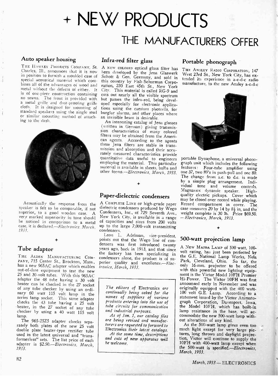
NEW PRODUCTS THE MANUFACTURERS OFFER
Auto speaker housing THE HAWLEY PRODUCTS COMPANY, St. Charles, Ill., announces that it is now in position to furnish a moulded case of special acoustical material which com- bines all of the advantages of wood and metal without the defects of either. It is of one-piece construction containing no seams. The front is provided with a metal grille and dust -proofing grille cloth. It is designed for mounting of standard speakers using the single stud or similar mounting method of attach- ing to the dash.
Acoustically the response from the speaker is felt to be comparable, if not superior, to a good wooden case. A very marked superiority in tone should be noticed in comparison to a metal case, it is declared. Electronics, March, 1933.
Tube adaptor THE ALDEN MANUFACTURING COM- PANY, 715 Center St., Brockton, Mass., has a new 965AC adapter which enables out-of-date equipment to test the new 25 and 30 -volt tubes. With this 965AC adapter the 48 tube having a 30 volt heater can be checked in the 27 socket of any tube checker by using an ordi- nary 60 watt 115 volt lamp in the series lamp socket. This same adapter checks the 43 tube having a 25 volt
heater, in the 27 socket of any tube checker by using a 40 watt 115 volt lamp.
The 965-25Z5 adapter checks sepa- rately both plates of the new 25 volt double plate heater -type rectifier tube used in the latest universal and "trans- formerless" sets. The list price of each adapter is $2.50. Electronics, March, 1933.
Infra -red filter glass A NEW COLORED optical glass filter has been developed by the Jena Glaswerk Schott & Gen, Germany, and sold in this country by Fish-Schurman Corpo- ration, 230 East 45th St., New York City. This material is called RG -9 and cuts out nearly all the visible spectrum but passes the infra -red, being devel- oped especially for electronic applica- tions using the caesium photcells, for burglar alarms, and other places where an invisible beam is desirable.
An interesting catalog of Jena glasses (written in German) giving transmis- sion characteristics of many colored filters may be obtained from the Ameri- can agents. According to the agents these Jena filters are stable in trans- mission and absorption and their accu- rately measured characteristics provide quantitative data useful to engineers employing the material. This particular material is available in sheets, bulbs and other forms. Electronics, March, 1933.
Paper -dielectric condensers A COMPLETE LINE OF high-grade paper dielectric condensers produced by Wego Condensers, Inc., of 729 Seventh Ave., New York City, is available in a range of capacities and sizes from 200 volts up to the large 7,000 -volt transmitting condensers.
Leon L. Adelman, vice-president, points out that the Wego line of con- densers was first introduced twenty years ago, back in 1913, and that since the factory has been specializing in condensers alone, the product is of su- perior quality and excellence.-Elec- tronics, March, 1933.
The editors of Electronics are continually being asked for the names of suppliers of various products entering into the use of tube circuits for conzmunication and industrial purposes.
As of Jan. 1, our catalog files are being revised and manufac- turers are requested to forward to Electronics their latest catalogs.
At the same time, descriptions and cuts of new apparatus will be welcome.
Portable phonograph THE ANSLEY RADIO CORPORATION, 147 West 23rd St., New York City, has ex- tended its experience in a -c -d -c radio manufacture, to the new Ansley a -c -d -c
portable Dynaphone, a universal phono- graph unit which includes the following features : Four -tube amplifier using one 37, two 89's in push-pull and one 80. The change from a.c. to d.c. is made by a simple plug arrangement. Indi- vidual tone and volume controls. Magnavox dynamic speaker. High - quality electric pickups. Cover which may be closed over record while playing. Record compartment in cover. The case measures 20 by 14 by 8¡ in, and the weight complete is 30 lb. Price $69.50. -Electronics, March, 1933.
500 -watt projection lamp A NEW MAZDA LAMP of 500 watt, 100 - volt rating, has just been perfected by the G.E. National Lamp Works, Nela Park, Cleveland, Ohio. So far, the only 16 -mm. projector to be offered with this powerful new lighting equip- ment is the Victor Model 10FH Premier Hi -Power. The Victor 10FH was first announced early in November and was originally equipped with the 400 watt - 100 volt G.E. Lamp. According to a statement issued by the Victor Animato - graph Corporation, Davenport, Iowa, the Model 10FH, which has built-in lamp resistance in the base, will ac- commodate the new 500 -watt lamp with- out alterations of any kind.
As the 500 -watt lamp gives even too much light except for very large pic- tures, long throws and daylight projec- tion, Victor will continue to supply the 10FH with 400 -watt lamp except when the 500 -watt is specified. Electronics, March, 1933.
82 March, 1933 - ELECTRONICS
www.americanradiohistory.com
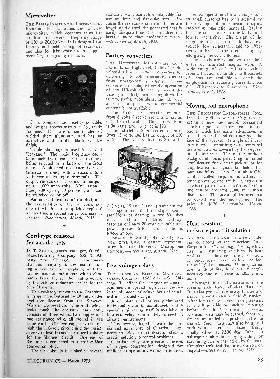
Microvolter THE FERRIS INSTRUMENT CORPORATION, Boonton, N. J., announces a new microvolter, which operates from the a.c. line, and covers a frequency range of 150 to 20,000 kc. It is designed for factory and field testing of receivers, and also for laboratory use to supple- ment larger signal generators.
It is compact and readily portable, and weighs approximately 20 lb., ready for use. The case is constructed of welded sheet aluminum, and has an attractive and durable black wrinkle finish.
Triple shielding is used to prevent "leakage." The radio frequency oscil- lator includes 6 coils, the desired one being selected by a knob on the front panel. A shielded resistance type at- tenuator is used, with a vacuum tube voltmeter at its input terminals. The output resistance is 5 ohms for outputs up to 1,000 microvolts. Modulation is fixed, 400 cycles, 30 per cent, and can be switched on or off.
An unusual feature of the design is the accessibility of the r -f coils, any one of which can be quickly replaced at any time a special range coil may be desired.-Electronics, March, 1933.
Cord -type resistors for a.c.-d.c. sets D. T. SIEGEL, general manager, Ohmite Manufacturing Company, 636 N. Al- bany Ave., Chicago, Ill., announces that his company is now manufactur- ing a new type of resistance unit for use on a.c.-d.c. radio sets which elim- inates from the set the heat produced by the voltage reduction needed for the tube filaments.
This resistor, known as the Cordohm, is being manufactured by Ohmite under exclusive license from the Stewart - Warner Corporation. The unit, which looks much like ordinary lamp cord, consists of three wires, two copper and one resistance wire, all wound in the same cord. The two copper wires fur- nish the 110 -volt circuit and the resist- ance wire lead furnishes reduced voltage for the filament circuit. One end of the unit is connected to a soft rubber connection plug.
'l'he Cordohm is furnished in several
standard resistance values adaptable for use on four and five -tube sets. Be- cause the resistance unit runs the entire length of the cord, the generated heat is easily dissipated and the cord does not become more than moderately warm. -Electronics, March, 1933.
Battery converters THE UNIVERSAL MICROPHONE COM- PANY, LTD., Inglewood, Calif., has de- veloped a line of battery converters for delivering 110 volts alternating current from storage -battery supply. These converters are adapted for the operation of any 110 -volt alternating -current de- vice, particularly sound amplifiers for trucks, parks, neon signs, and all port- able uses in places where commercial current is not available.
The Model 60 converter operates from 6 volts direct -current, and has an output of 60 watts. The battery drain is 90 watts, and the price is $28.
The Model 150 converter operates from 12 volts, and has an output of 150 watts. The battery drain is 216 watts
(12 volts, 18 amp.) and is sufficient for the operation of three -stage sound amplifiers terminating in two 50 tubes in push-pull, and in addition will op- erate an ordinary 20 -watt turntable and power -speaker field. This model is priced at $60.
Howard F. Smith, 142 Liberty St., New York City, is eastern represent- ative for the Universal Microphone Company. Electronics, March, 1933.
+
Low -voltage relays THE GUARDIAN ELECTRIC MANUFAC- TURING COMPANY, 1522 Adams St., Chi- cago, Ill., offers the designer of control equipment a special high-speed service in the shipment of relays, both of stand- ard and special design.
A complete stock of many thousand individual parts is maintained, and a special engineering staff is available to fabricate relays immediately to meet all circuit requirements.
This service, together with the spe- cialized experience of Guardian engi- neers in relay circuit design, offers a certain solution to control problems.
Guardian relays are precision devices of rugged construction, designed for millions of operations without attention.
Perfect operation at low voltages and on small currents has been secured by the development of unusual designs, employing magnetic materials having the higest possible permeability and lowest retentivity. The design of the magnetic path is such as to have ex- tremely low reluctance, and to effec- tively utilize all the flux set up by energizing the coil windings.
These coils are wound with the best grade of insulated magnet wire. A wide range of coil resistance values from a fraction of an ohm to thousands of ohms, are available to permit the employment of actuating currents from 0.5 milliamperes to 5 amperes.-Elec- tronics, March, 1933.
Moving -coil microphone THE THOMASTON LABORATORIES, INC., 135 Liberty St., New York City, is mar- keting a new moving -coil permanent cobalt -magnet electrodynamic micro- phone which has many advantages in use. It is small, and does not hide the face of the speaker, its angle of incep- tion is wide, permitting non -directional use over an area covered by 135 degrees in all directions. The unit is without background noise, permitting unlimited amplification for distant pick-up or for amplification of signals far below hu- man audibility. This TomLab MC30, as it is called, requires no battery or other power to operate it. Simply run a twisted pair of wires, and this 30 -ohm line can be operated 1,000 ft. without distortion. The pre -amplifier need not be located near the microphone. The price is $125.-Electronics, March, 1933.
Heat -resistant moisture -proof insulation ALSIMAG IS THE NAME of a new mate- rial developed by the American Lava Corporation, Chattanooga, Tenn., which has high insulating qualities, is heat resistant, has low moisture absorption, is non -corrosive, and has low loss fac- tor at high frequencies. Other qualities are its durability, hardness, strength, accuracy and resistance to alkalis and acids.
Alsimag is formed by extrusion in the form of rods, bars, cylinders, flats, etc. It is also pressed accurately to size and shape, in most cases to final dimension. After forming by extrusion or pressing, it is still possible to machine Alsimag before the final hardening process. Alsimag parts may be turned, threaded, drilled or milled to produce intricate shapes. Such parts may also be glazed with white or colored glazes. Being finally kilned at 2,500 deg. Fahr., no subsequent alterations by grinding or machining can be carried on by the user. Complete technical data are available on request. Electronics, March, 1933.
ELECTRONICS - March, 1933 83
www.americanradiohistory.com

Airport receiver LEAR DEVELOPMENTS, INC., 847 W. Harrison St., Chicago, Ill., announce their new Radio -Aire airport radio re- ceiver which is now in production.
This receiver is a distinct departure in a long -wave set covering the entire frequency band of 235 to 720 kc. It is a portable radio of special interest to airports, hangars, pilots, aircraft offi-
cials and everyone interested in aircraft operation. It enables air enthusiasts to keep in touch with weather conditions, naval communications and also to enjoy entertainment program broadcasts.
It is self-contained, all electric, a. -c. operated, with full dynamic speaker. Especially built for commercial de- mands, it is of extremely high quality and dependability, and is not to be confused with ordinary radios.
The tone quality on the entertainment broadcast range matches the finest home radio. Litz wire, low loss, high gain inductances invented and developed by Lear, permit the wide tuning range, high sensitivity and sharp selectivity. The list price is $89.50. Electronics, March, 1933.
Moulded paper -pulp diaphragm THE UNITED PRESS PRODUCTS COMPANY, 400 West Erie St., Chicago, Ill., has developed a moulded -paper pulp dia- phragm, which is remarkably accurate in its production of music and speech. The cone construction is seamless, with the voice collar and suspension integral with the cone proper, which eliminates all seams of the old type cone design, distortion, noises, lack of uniformity, and chance of seams opening up during performance.
A new, automatic process of manu- facturing these cones has been devel- oped, in which all the elements of make-up of the cone are under control. The mass, or weight, of cone can be varied by adjustability in the machinery, and the cone can be brought to any desired weight, and so maintained in production to within small limits of variation. Even the most delicate cones can be produced.
The second element of importance is
the control of paper pulp by formula. Various combinations of pulp and chemicals can be combined and main- tained to give any degree of softness or hardness, which reflects itself in the low and high frequencies. Any special design can be moulded and then pressed to any degree of hardness. Control through adjustability can be had in the process to give a greater flexibility to the suspension, as compared with the cone proper. Other incidental points of control in the process permit the manufacture of the most desirable characteristics for any individual speaker design. - Electronics, March, 1933.
Self -tapping screws THE KELLOGG SWITCHBOARD AND SUP- PLY COMPANY, 1066 West Adams St., Chicago, Ill., has developed its Tapster screws for assembly purposes wherever the fastening of metals, bakelite, slate, fibre, ebony -asbestos, and similar hard materials is involved. The feature of this new screw is its own pair of cut- ting edges which tap out the thread ahead of the screw and so make a very snug fit, compared with ordinary ma- chine screws in tapped holes. This gives the whole assembly greater strength in resisting vibration, shear and stress, according to the manufac- turers. The new Tapster screw with balanced flutes can also be used in many places where the usual self -tapping screw which merely pushes the metal aside would not be adaptable, it is declared. Tapster screws are made in various standard -thread types, and can be retracted and re -driven without injury to themselves or the threaded holes. Use of screws of this kind may save from 40 to 75 per cent of the cost of assembly operations. - Elec- tronics, March, 1933.
Full -wave converter and time -delay unit THE NEW WEBSTER FULL -WAVE CON- VERTER and time -delay unit combines efficiency and reliability in automobile B eliminator supply because it is a com- bination interrupter and rectifier in one unit. There is no need for further rectification, therefore the rectifier tube, and its attendant losses are entirely eliminated from the design. Because of the self -rectifying features, a high order -of regulation can be maintained. The primary and secondary contacts are so synchronized to reduce sparking to an absolute minimum. Efficiency in ex- cess of 60 per cent is easily obtainable. An automatic time -delay device, which delays application of the B supply volt- age until the tubes in the radio set attain operating temperature. In its present form, the Webster full -wave converter and time -delay unit is made as a re-
placeable unit, replacement being as simple as changing a tube. The unit is hermetically sealed in a bakelite hous- ing. It can be furnished for operation on either 6 volts, 12 volts or other voltages. Made by the Webster Com- pany, 3825 W. Lake St., Chicago, Ill.- Electronics, March, 1933.
Portable and pocket -type instrument THE ROLLER -SMITH COMPANY, 233 Broadway, New York City, announces a new line of Steel -Six portable instru- ments. The outstanding features of these instruments are their steel cases, which are very rugged and which shield the mechanism against the effect of ex- ternal magnetic influences ; usually long scales; high accuracy; open and well lighted dials; fusing when desired; a very complete line, comprising direct current ammeters, milliammeters, volt- meters, millivoltmeters and volt -am- meters and alternating current am- meters, milliammeters, voltmeters, single and polyphase wattmeters, frequency meters and power factor meters.
The HTA and HTD small, pocket - type portables, which were taken off the market some time ago, are now being reinstated on account of an insistent demand for a complete line of small portable instruments for miscellaneous applications. The line includes direct current ammeters, mil- liammeters, voltmeters, millivoltmeters and volt -ammeters and alternating cur- rent ammeters, milliammeters and volt- ammeters.-Electronics, March, 1933.
Slide -wire rheostat A SMALL, HIGH QUALITY, inexpensive slide -wire rheostat for radio experi- menters, and manufacturers of electrical equipment is announced by G -M Lab- oratories, Inc., 1735 Belmont Ave., Chicago, Ill., in their type R rheostat. Wound on a one-piece porcelain form, with adjustable contact for varying the resistance, this unit is designed for maximum service and convenience. It will dissipate 75 watts continuously.
These rheostats are wound with wire having low temperature coefficient of resistance, and can be supplied in 12 ratings from 5,000 ohms, 0.12 amperes to 4.8 ohms, 4 amperes. Binding screws at each end of the winding permit the use of any type R rheostat as a po- tentiometer. Considerable overloading for brief intervals will not permanently damage the rheostat. - Electronics, March, 1933.
84 March, 1933 - ELECTRONICS
www.americanradiohistory.com
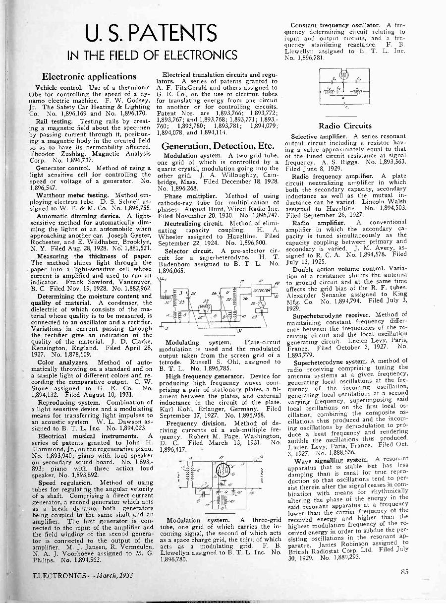
U. S. PATENTS IN THE FIELD OF ELECTRONICS
Electronic applications Vehicle control. Use of a thermionic
tube for controlling the speed of a dy- namo electric machine. F. W. Godsey, Jr. The Safety Car Heating & Lighting Co. No. 1,896,169 and No. 1,896,170.
Rail testing. Testing rails by creat- ing a magnetic field about the specimen by passing current through it, position- ing a magnetic body in the created field so as to have its permeability affected. Theodor Zushlag, Magnetic Analysis Corp. No. 1,896,737.
Generator control. Method of using a light sensitive cell for controlling the speed or voltage of a generator. No. 1,896,547.
Watthour meter testing. Method em- ploying electron tube. D. S. Schnell as- signed to W. E. & M. Co. No. 1,896,755.
Automatic dimming device. A light- sensitive method for automatically dim- ming the lights of an automobile when approaching another car. Joseph Gyster, Rochester, and E. Wildhaber, Brooklyn, N. Y. Filed Aug. 28, 1928. Nò. 1,881,521.
Measuring the thickness of paper. The method shines light through the paper into a light-sensitive cell whose current is amplified and used to run an indicator. Frank Sawford, Vancouver, B. C. Filed Nov. 19, 1928. No. 1,882,962.
Determining the moisture content and quality of material. A condenser, the dielectric of which consists of the ma- terial whose quality is to be measured, is connected to an oscillator and a rectifier. Variations in current passing through the rectifier give an indication of the quality of the material. J. D. Clarke, Kensington, England. Filed April 28, 1927. No. 1,878,109.
Color analyzers. Method of auto- matically throwing on a standard and on a sample light of different colors and re- cording the comparative output. C. W. Stone assigned to G. E. Co. No. 1,894,132. Filed August 10, 1931.
Reproducing system. Combination of a light sensitive device and a modulating means for transferring light impulses to an acoustic system. W. L. Dawson as- signed to B. T. L. Inc. No. 1,894,023.
Electrical musical instruments. A series of patents granted to John H. Hammond, Jr., on the regenerative piano. No. 1,893,940; piano with loud speaker on secondary sound board. No. 1,893,- 893; piano with three action loud speaker, No. 1,893,892.
Speed regulation. Method of using tubes for regulating the angular velocity of a shaft. Comprising a direct current generator, a second generator which acts as a break dynamo, both generators being coupled to the same shaft and an amplifier. The first generator is con- nected to the input of the amplifier and the field winding of the second genera- tor is connected to the output of the amplifier. M. J. Jansen, R. Vermeulen, N. A. J. Voorhoeve assigned to M. G. Philips. No. 1,894,562.
Electrical translation circuits and regu- lators. A series of patents granted to A. F. FitzGerald and others assigned to G. E. Co., on the use of electron tubes for translating energy from one circuit to another or for controlling circuits. Patent Nos. are 1,893,766; 1,893,772; 1,893,767; and 1,893,768; 1,893,771; 1,893,- 760; 1,893,780; 1,893,781; 1,894,079;' 1,894,078, and 1,894,114.
Generation, Detection, Etc. Modulation system. A two -grid tube,
one grid of which is controlled by a quartz crystal, modulation going into the other grid. J. A. Willoughby, Cam- bridge, Mass. Filed December 18, 1928. No. 1,896,268.
Phase multiplier. Method of using cathode-ray tube for multiplication of phases. August Hunt, Wired Radio Inc. Filed November 20, 1930. No. 1,896,747.
Neutralizing circuit. Method of elimi- nating capacity coupling. H. A. Wheeler assigned to Hazeltine. Filed September 22, 1924. No. 1,896,500.
Selector circuit. A pre -selector cir- cuit for a superheterodyne. H. T. Budenbom assigned to B. T. L. No. 1,896,065. \ LI
/7
e24 26,6 ,
i
ao
crrfcrav
Modulating system. Plate -circuit modulation is used and the modulated output taken from the screen grid of a tetrode. Russell S. Ohl, assigned to B. T. L. No. 1,896,785.
High frequency generator. Device for producing high frequency waves com- prising a pair of stationary. plates, a fil- ament between the plates, and external inductance in the circuit of the plate. Karl Kohl, Erlanger, Germany. Filed September 17, 1927. No. 1,896,958.
Frequency division. Method of de- riving currents of a sub -multiple fre- quency. Robert M. Page, Washington, D. C. Filed March 13, 1931. No. 1,896,417. -
Modulation system. A three -grid tube, one grid of which carries the in- coming signal, the second of which acts as a space charge grid, the third of which acts as a modulating grid. F. B. Llewellyn assigned to B. T. L. Inc. No. 1,896,780.
Constant frequency oscillator. A fre- quency determining circuit relating to input and output circuits, and a fre- quency stabilizing reactance. F. B. Llewellyn assigned to B. T. L. Inc. No. 1,896,781.
Radio Circuits Selective amplifier. A series resonant
output circuit including a resistor hav- ing a value approximately equal to that of the tuned circuit resistance at signal frequency. A. S. Riggs. No. 1,893,563. Filed June 8, 1929.
Radio frequency amplifier. A plate circuit neutralizing amplifier in which both the secondary capacity, secondary inductance as well as the mutual in- ductance can be varied. Lincoln Walsh assigned to Hazeltine. No. 1,894,503. Filed September 26, 1927.
Radio amplifier. A conventional amplifier in which the secondary ca- pacity is tuned simultaneously as the capacity coupling between primary and secondary is varied. J. M. Avery, as- signed to R. C. A. No. 1,894,578. Filed July 13, 1925.
Double action volume control. Varia- tion of a resistance shunts the antenna to ground circuit and at the same time affects the grid bias of the R. F. tubes. Alexander Senauke assigned to King Mfg. Co. No. 1,894,794. Filed July 3,
1929. Superheterodyne receiver. Method of
maintaining constant frequency differ- ence between the frequencies of the re- ceiving circuit and the local oscillation generating circuit. Lucien Levy, Paris, France. Filed October 3, 1927. No. 1,893,779.
Superheterodyne system. A method of
radio receiving comprising tuning the antenna systems at a given frequency, generating local oscillations at the fre- quency of the incoming oscillation, generating local oscillations at a second varying frequency, superimposing said
local oscillations on the first local os-
cillation, combining the composite os-
cillations thus produced and the incom-
ing oscillations by demodulation to pro- duce a beat frequency and rendering audible the oscillations thus produced. Lucien Levy, Paris, France. Filed Oct.
3, 1927. No. 1,888,536.
Wave signalling system. A resonant apparatus that is stable but has less
damping than is usual for true repro-
duction so that oscillations tend to per-
sist therein after the signal ceases in com-
bination with means for rhythmicallythe
altering the phase of the energy in
said resonant apparatus at a frequency lower than the carrier frequency of the
received energy and higher than the
highest modulation frequency of the re-
ceived energy in order to subdue the per-
sisting oscillations in the resonant ap-
paratus. James Robinson assigned to
British Radiostat Corp. Ltd. Filed July 30, 1929. No. 1,889,293.
ELECTRONICS - March, 1933 85
www.americanradiohistory.com
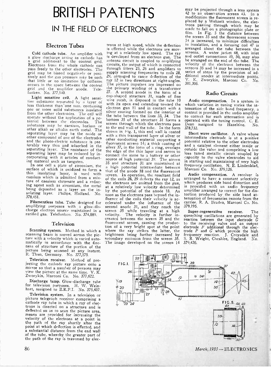
BRITISH PATENTS IN THE FIELD OF ELECTRONICS
Electron Tubes Cold cathode tube. An amplifier with
a glow discharge acting as cathode has a grid additional to the control grid. Electrons from the whole cathode can pass freely to the other electrodes. The grid may be biased negatively or posi- tively and the gas pressure may be such that little or no ionization by collision occurs in the space between the control grid and the amplifier anode. Tele- funken. No. 377,540.
Light sensitive cell. A light sensi- tive substance separated by a layer of less thickness thanone mm. containing one or more solid substances insulated from the other electrodes. The cell will operate without the application of a po- tential between the electrodes. The substance may be caesium, barium or other alkali or alkalin earth metal. The separating layer may be the oxide or other compound of one of the electrodes and the photo -electric substance is pre- ferably very thin and adsorbed in the separating layer. The resistance of the separating layer may be reduced by in- corporating with it articles of conduct- ing material such as tungsten.
In one cell a plate of zirconium, the surface of which is oxidized to form a thin insulating layer, is used with caesium which is admitted from a mix- ture of caesium chromate and a reduc- ing agent such as zirconium, the metal being deposited as a layer on the in- sulating layer. Philips, Holland. No. 378,451.
Filamentless tube. Tube designed for amplifying purposes with a glow -dis- charge electron source maintained in a rarified gas. Telefunken. No. 374,889.
Television Scanning system. Method in which a
scanning beam is moved across the pic- ture with a velocity which is varied auto- matically in accordance with the fine- ness of structure of the portion of the picture being scanned at any instant. R. Thun, Germany. No. 377,175.
Television receiver. Method of pro- jecting the cathode ray picture onto a mirror so that a number of persons may view the picture at the same time. V. K. Zworykin, Marconi Co. No. 377,622.
Discharge lamp. Glow -discharge tube for television purposes. H. W. Wein- hart, assigned to E.R.P.I. No. 375,407.
Television system. In a television or picture telegraph receiver comprising a cathode ray tube in which a ray of elec- trons is directed on a structure and is deflected so as to scan the picture area, means are provided for increasing the velocity of the electrons at a point in the path of the ray shortly after the point at which deflection is effected, and a substantial distance from the end wall of the tube, whereby the greater part of the path of the ray is traversed by elec-
trons at high speed, while the deflection is effected while the electrons are mov- ing at a relatively low speed. The ray is developed from an electron gun. The antenna circuit is coupled to amplifying circuits, the output of which is connected through filters 25, 26 and amplifiers to supply scanning frequencies to coils 28, 29, arranged to cause deflection of the ray 12 in two directions at right -angles. The picture impulses are impressed on the primary winding of a transformer 27. A second anode in the form of a cup -shaped structure 31, made of fine wire mesh, is disposed in the tube 10 with its open end extending toward the electron gun 11 and in contact with a silver coating formed on the interior of the tube between the lines 33, 34. The bottom 35 of the structure 31 forms a screen through which the electrons pass to the end wall of the tube. In the form shown in Fig. 1, this end wall is coated with a thin transparent layer of silver or other conducting material supporting a fluorescent screen 14; a thick coating of silver 37, in the form of a ring, overlaps the edge of the thin layer and serves to connect the same to a battery or other source of high potential 39. The screen 35 and structure 31 are maintained at a high potential intermediate between that of the anode 18 and the fluorescent screen. In operation, the resultant field of the coils 28, 29 deflects the ray 12, as the electrons are emitted from the gun, at a relatively low velocity determined by the potential of the anode 18. As soon as the electrons pass beyond the in- fluence of the coils their velocity is ac- celerated under the influence of the second anode 31, and they reach the screen 35 while traveling at a high velocity. The velocity is further in- creased between the screen 35 and the fluorescent screen, causing the produc- tion of a very bright spot at the point where the ray strikes the latter, the brightness being further increased by secondary emission from the screen 35. The image developed on the screen 14
may be projected through a lens system 42 to an observation screen 43. In a modification the fluorescent screen is re- placed by a Wehnelt window, the elec- trons passing through which may be made to fall on a photographic plate or film. In Fig. 5 the distance between the screen 35 and the fluorescent screen 14 is increased, to minimize difficulties in insulation, and a focusing coil 47 is arranged about the tube between the screens. A water jacket 48, with inlet and outlet connections 49, 50, may also be arranged on the end of the tube. The velocity of the electrons between the screens 35 and 14 may be increased in a series of steps by the provision of ad- ditional anodés at intermediate points. V. K. Zworykin, Marconi Co. No. 381,306.
Radio Circuits Audio compensation. In a system in
which variation in tuning varies the at- tenuation of the side band frequency, a control is provided in the audio amplifier to correct for such attenuation and is operated with the tuning control. C. E. Dean assigned to Hazeltine. No. 378,733.
Short wave oscillator. A valve whose intermediate electrode is at a positive potential relative to the other electrodes and a catalyst element either inside or outside the valve and comprising a low loss tuned metallic circuit coupled by capacity to the valve electrodes to aid in starting and maintaining of very high frequency oscillation. N. E. Lindenblad, Marconi Co. No. 379,126.
Audio compensation. A receiver is arranged to have a constant selectivity which produces side band distortion and is provided with an audio frequency amplifier arranged to correct for the dis- tortion produced by the side band at- tenuation of frequencies remote from the carrier. R. A. Braden, Marconi Co. No. 379,195.
Super -regenerative receiver. The quenching oscillations are generated by reaction between the input electrode G to the receiving valve and an output electrode F additional through the elec- trode P and G which provide the high frequency reaction. J. Croysdale and S. R. Wright, Cheshire, England. No. 379,426.
86 March, 1933 - ELECTRONICS
www.americanradiohistory.com