characterization and applications of discrete memristorparthchadha.github.io/paper1.pdf · parth...
TRANSCRIPT

Characterization and applications of discretememristor
Parth ChadhaDept. of Electrical andElectronics Engineering
Delhi Technological UniversityEmail:[email protected]
Shikhar KwatraDept. of Instrumentation and
Control EngineeringNetaji Subash Institute of Technology
Email:[email protected]
Gaurav GandhimLabs
New Delhi,IndiaEmail: [email protected]
Varun AggarwalmLabs
New Delhi,IndiaEmail: [email protected]
Abstract—In the present paper, we study the electricalproperties of cat’s whisker, subset of a larger class of devicescalled coherer, which were recently proposed to be a canonicalimplementation of memristor. The devices memristive propertieswere found to be dependent on the contact area and pressure.The maximum current flown through the device is found to bethe controlling state-variable. By controlling the state-variable,we found that the device can be programmed into multipleresistance states and can be reset to higher resistance state,which has immediate application in programmable analogcircuits. We have demonstrated that by using programmingcurrent wave, we can achieve programming of properties suchas threshold voltage, amplifiers gain and duty cycle.
I. INTRODUCTION
Memristors are passive non-linear resistive elements whoseresistance is dependent on the history of the system. Thefunctional properties of the memristor was first proposed byLeon O.Chua in 1971 [2] showing the existence of new passivetwo terminal device in class of memory circuit elements.The realization of the memristor came in 2008 when HPannounced the first nanoscale memristor [9]. It was discoveredin the form of a partially doped titanium dioxide on nanoscalethin film with platinum electrodes [10].Since its realization in 2008, recent interest has been driven bythe realization that memristors are likely to have a significantimpact in electronic circuit design both in digital and analogcircuits [5], [7]. Recent work shows that it has an application innon-volatile memory storage and also offers advanced analogfunctionalities. The memristor is also proposed to be electricalequivalent of a synapse and hence is believed to play animportant role in neuromorphic computing and learning [6].The application of memristive circuits and the availability ofmemristors in nanoscale, has sparked the need for a discretecomponent for fast prototyping.Recently Gaurav et.al [3], [4] have shown the canonical imple-mentation of a memristor consists of devices having imperfectmetal-metal contact as in coherer or metal-semiconductorpoint contact as in cat’s whisker detector(also called crystaldetector).In case of bipolar input, these devices form a pinched hystersisloop, which is a fingerprint for memristive devices. Thoughthese devices show memristive behaviour and some other
interesting phenomena, it is highly sensitive to the point ofcontact and the pressure applied.In the present paper we discuss about the experimentalresults on electrical characteristics of this discrete mem-ristor and an approach to use it in programmable analogcircuits. Applications such as programmable gain amplifier,programmable threshold comparator, programmable switchingthresholds Schmitt trigger have been implemented and exper-imental results are presented.This paper is organized as follows. Section II of this paperdiscusses the electrical properties of cat’s whisker and describethe experimental setup we used to perform experiments.Insection III we demonstrate applications of this memristor inanalog circuits and conclude in section IV.
II. DISCRETE MEMRISTOR
The discrete memristor studied in this paper comprises of ametal-semiconductor point contact based device called as cat’swhisker detector. This device was earlier used in radio wavedetector due to its diode-like rectifying properties [1][8].The device was found to be state-dependent resistor wherethe state variable governing it, is found to be the maximumcurrent that has passed through the device Imax [3].We found that the device is highly sensitive to the pressureapplied and the point of contact and the nature of the I-Vcurve changes depending on these two factors.To provide current mode input an experimental setup was used,discussed next. A detailed analysis of class of devices calledcoherer can be found in [3],[4].
A. Experimental Setup
Flow diagram for operation of experimental setup is shownin Figure 1. The core circuit of the setup was designed usingcommercially available components. The main componentsinstalled in the current board include AD844 (current feed-back operational amplifiers), MCP4725 (12-Bit I2C Digitalto Analog Converter),AD620 (Instrumentation Amplifier IC).AD620AN is a low Drift, low power Instrumentation Amplifierwith set gains of 1 to 10000.In our experimental setup, we provided current mode input tothe device and measured the output voltage across it. To supplythe current waveform, Current feedback operational amplifier

is used. AD844 AN is 60MHz, 2000 V/s Monolithic Op Ampis used for voltage to current conversion.
Fig. 1. Working flow diagram of breakout board
B. Experimental Results
For cat’s whisker detector setup, memristive behaviourrepeats within the same range of resistances for the same spotof cat’s whisker and its properties are dependent on the spotwhere cat’s whisker touches the crystal.It was found that the nature of I-V curves such as the non-linearity, resistance range, threshold voltage (Vth) is found tobe dependent on the area, location and the pressure applied.The device transient electrical characteristics are studied bymeasuring voltage across the device when current as input isprovided.
Fig. 2. a) Current wave input to device. b) Plot showing Imax behaviour.
1) Imax behaviour: For the analysis of the Imax behaviour,input current waveform as shown in Figure 2(a) is provided.
The corresponding transient output voltage is measured.The triangle current waveforms are of peak sequence 1mA,1.5mA, 2.5mA, 3mA and 1.5mA in Figure 2(a).The resultant I-V curve obtained is as shown in Figure 2(b).The resistance decreases with every input current pulse ofhigher peak value but remained essentially non-linear. It isfurther observed that the resistance value adjusts such thatmaximum voltage across device remains around the thresholdvoltage Vth. The Vth over many samples is found to bedependent on the spot and the pressure of cat’s whisker onthe crystal.The device retraces the previous I-V curve when smalleramplitude current peak is provided and hence can be used toread the previous resistance.
Fig. 3. Plot showing reset behaviour
2) Bipolar memristive characterstics: For the analysis ofbipolar memristive characterstics of the discrete memristor,input current waveform as shown in Figure 3 is supplied.The current peaks are of amplitude +-3mA. The correspondingtransient output voltage is measured.As seen from the Figure 3, the device resistance gets adjustedto one state in positive direction and another state in negativedirection. It traces these fixed resistances in both direction,when switched from positive to negative and vice versa andhence shows a pinched hysteresis loop.The device gets programmed in each direction by a largepositive/negative input peak current and remains in the sameresistance state when provided with a smaller input current. Itswitches its resistance when provided with a large input currentpeak in opposite direction. Hence the device can be used inresistive memory, in which large pulses write information andsmall pulses can be used to read information and to reset thedata, a large negative pulse is given.
III. PROGRAMMABLE ANALOG CIRCUITS
Based on the detailed electrical analysis in section II, wefind that -
1) Device can be programmed by high amplitude currentpulses and low amplitude current pulses can be used inanalog operation.
2) Each programming current pulse changes the resistanceby a discrete amount.
With the above properties, device can be used in number ofanalog circuits. Some of them are shown here.
A. Programmable gain amplifier
We start by demonstrating programmable amplifier based ondiscrete memristor. The schematic of this circuit is as shownin Figure 4.
Fig. 4. Schematics of a programmable gain amplifier
The programming current I is given by I = Vin/R and theoutput voltage Vout is given by Vout = I ∗M(r), where M(r)is the device resistance and R = 1kΩ.Hence the ratio of output to input voltage is given by-
Vout/Vin = M(r)/R (1)
0 2 4 6 8 10 12 14 16 18 20−5
0245
Pro
gra
mm
ing
Curr
ent(
mA
)
0 2 4 6 8 10 12 14 16 18 20−2.5
0
0.5
1
1.5
2
2.5
3
3.5
4
Time (s)
Outp
ut V
oltage (
V)
Fig. 5. In these measurements, voltage Vin is kept constant to 0.5V in analogoperation. Programming current consists of 2mA, 4mA and 5mA trianglepulses.
Experimental results are as shown in Figure 5. Amplifier’sgain is controlled using triangular current pulses. As shownin figure the output voltage decreases when the device isprogrammed with 2mA, 4mA and 5mA triangle current peaks.Gain is observed to decrease in each case when input voltageVin is kept constant to 0.5V. Gain increases to original valuewhen negative current peak is provided which resets the deviceresistance. The gain of the circuit changes by 11.7%.
B. Programmable threshold comparator
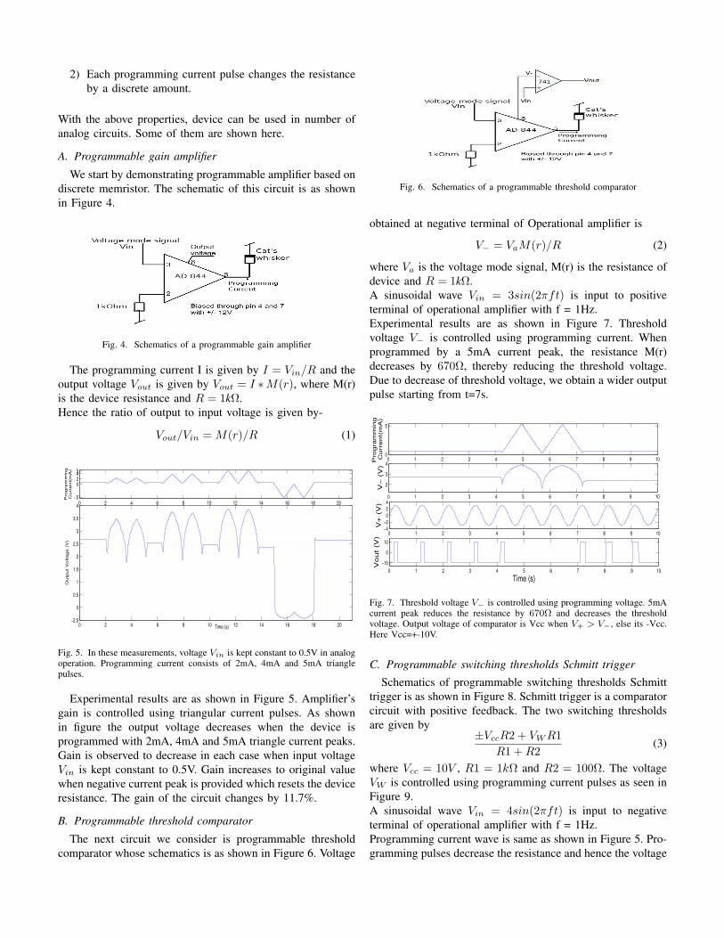
The next circuit we consider is programmable thresholdcomparator whose schematics is as shown in Figure 6. Voltage
Fig. 6. Schematics of a programmable threshold comparator
obtained at negative terminal of Operational amplifier is
V− = VaM(r)/R (2)
where Va is the voltage mode signal, M(r) is the resistance ofdevice and R = 1kΩ.A sinusoidal wave Vin = 3sin(2πft) is input to positiveterminal of operational amplifier with f = 1Hz.Experimental results are as shown in Figure 7. Thresholdvoltage V− is controlled using programming current. Whenprogrammed by a 5mA current peak, the resistance M(r)decreases by 670Ω, thereby reducing the threshold voltage.Due to decrease of threshold voltage, we obtain a wider outputpulse starting from t=7s.
0 1 2 3 4 5 6 7 8 9 100
5
Pro
gra
mm
ing
Curr
ent(
mA
)
0 1 2 3 4 5 6 7 8 9 10
2
3
4
V−
(V
)
0 1 2 3 4 5 6 7 8 9 10−4
−2
0
2
4
V+
(V
)
0 1 2 3 4 5 6 7 8 9 10
−10
0
10
Time (s)
Vo
ut
(V)
Fig. 7. Threshold voltage V− is controlled using programming voltage. 5mAcurrent peak reduces the resistance by 670Ω and decreases the thresholdvoltage. Output voltage of comparator is Vcc when V+ > V−, else its -Vcc.Here Vcc=+-10V.
C. Programmable switching thresholds Schmitt trigger
Schematics of programmable switching thresholds Schmitttrigger is as shown in Figure 8. Schmitt trigger is a comparatorcircuit with positive feedback. The two switching thresholdsare given by
±VccR2 + VWR1
R1 +R2(3)
where Vcc = 10V , R1 = 1kΩ and R2 = 100Ω. The voltageVW is controlled using programming current pulses as seen inFigure 9.A sinusoidal wave Vin = 4sin(2πft) is input to negativeterminal of operational amplifier with f = 1Hz.Programming current wave is same as shown in Figure 5. Pro-gramming pulses decrease the resistance and hence the voltage

Fig. 8. Schematics of a programmable switching thresholds Schmitt trigger
at VW decreases. With decrease of Voltage VW the thresholddecreases in both direction i.e. positive threshold magnitudedecreases and negative threshold magnitude increases. As aresult, the output voltage Vout occurs at different values ofVin.
Fig. 9. Programmable switching threshold output response with input voltageVin = 4sin(2πft) with f=1Hz, and V+ varying due to programming pulses.The figure also shows the reset effect which resets the threshold to its originalvalue.
IV. CONCLUSION
The behaviour of the metal-semiconductor point con-tact(cats whisker device) memristor is discussed. We haveobserved that the device’s electrical characteristics dependupon the area, pressure and location of cats whisker and thenature of I-V curves changes accordingly.By controlling the state-variable, we found that the deviceshows two types of behaviour, Imax and Reset. Observationsover large number of samples show that the device can beprogrammed into multiple resistance ranges by different largeamplitude current peaks and device state can be read by smallcurrent peaks.It is observed that the I-V behaviour in bipolar current modeinput is asymmetric and with large negative current peak thedevice reset to a higher resistance state. Small positive currentcan be used to read the higher resistance state.Since the device resistance state was found to be a a func-tion of Imax, it has usage in applications involving multipleresistance states including multi-bit storage, programmable
amplifier etc.Analog circuits have earlier been implemented in [7], but usinga memristor emulator. We have demonstrated the operation andexperimental data of these programmable analog circuits usingdiscrete memristor. By using programming current wave, wehave achieved programming of properties such as thresholdvoltage, amplifier’s gain, duty cycle.We have thus shown that by controlling the state-variable ofcats whisker detector, or class of devices called coherers, wecan achieve useful analog circuits.
V. ACKNOWLEDGEMENT
The authors would like to thank Prof. Leon Chua for hishelp and suggestions.
REFERENCES
[1] J.C. BOSE. Detector for electrical disturbances, March 29 1904. USPatent 755,840.
[2] L. Chua. Memristor-the missing circuit element. Circuit Theory, IEEETransactions on, 18(5):507–519, 1971.
[3] G. Gandhi and Aggarwal. Bipolar electrical switching in metal metalcontacts. mlabs report [online].
[4] G. Gandhi, V. Aggarwal, and L. Chua. The first radios were made usingmemristors! Circuits and Systems Magazine, IEEE, 13(2):8–16, 2013.
[5] M. Itoh and L.O. Chua. Memristor oscillators. Int. J. Bifur. Chaos,18(11):3183–3206, 2008.
[6] S.H. Jo, T. Chang, I. Ebong, B.B. Bhadviya, P. Mazumder, and W. Lu.Nanoscale memristor device as synapse in neuromorphic systems. Nanoletters, 10(4):1297–1301, 2010.
[7] Y.V. Pershin and M. Di Ventra. Practical approach to programmableanalog circuits with memristors. Circuits and Systems I: Regular Papers,IEEE Transactions on, 57(8):1857–1864, 2010.
[8] VJ Philips. The italian navy coherer affair: A turn of the century scandal,reproduced in proc. Of IEEE, 86(1), 1998.
[9] D.B. Strukov, G.S. Snider, D.R. Stewart, and R.S. Williams. The missingmemristor found. Nature, 453(7191):80–83, 2008.
[10] R. Williams. How we found the missing memristor. Spectrum, IEEE,45(12):28–35, 2008.