chapter 9 panko and panko business data networks and security, 9 th edition © 2013 pearson revised...
TRANSCRIPT
TCP/IP Internetworking II
Chapter 9
Panko and PankoBusiness Data Networks and Security, 9th Edition© 2013 Pearson
Revised August 2013

Chapter (s)
Coverage Layers
1–4 Core concepts and principles All
5 Single switched networks 1–2
6–7 Single wireless networks 1–2
8–9 Internets 3–4
10 Wide Area Networks 1-4
11 Applications 5
© 2013 Pearson 2
Perspective

Chapter 8◦ Major TCP/IP standards
◦ Router operation
Chapter 9◦ Managing Internets
◦ Securing Internets
© 2013 Pearson 3
Perspective

IP Subnetting
Network Address Translation (NAT)
DNS and DHCP
SNMP
Multiprotocol Label Switching
Securing Internet Transmission
IPv6 Management
© 2013 Pearson 4
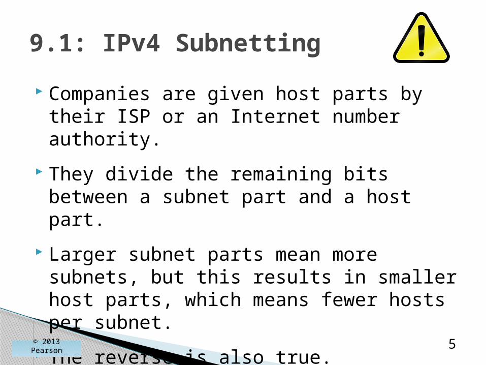
Companies are given host parts by their ISP or an Internet number authority.
They divide the remaining bits between a subnet part and a host part.
Larger subnet parts mean more subnets, but this results in smaller host parts, which means fewer hosts per subnet.
The reverse is also true.
© 2013 Pearson 5
9.1: IPv4 Subnetting
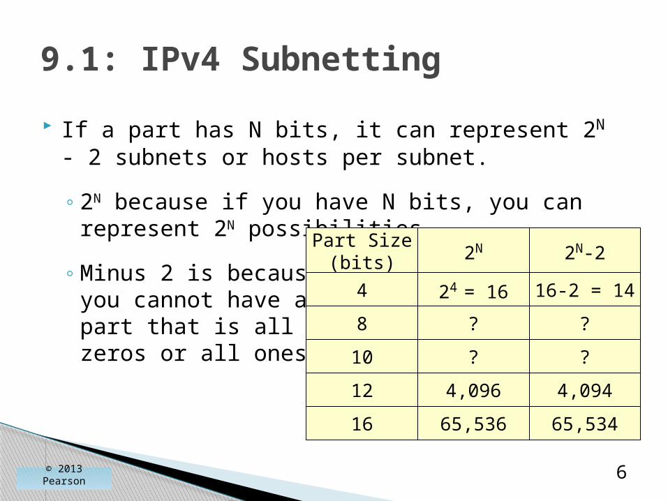
If a part has N bits, it can represent 2N - 2 subnets or hosts per subnet.
◦ 2N because if you have N bits, you can represent 2N possibilities.
◦ Minus 2 is because you cannot have a part that is all zeros or all ones.
© 2013 Pearson 6
9.1: IPv4 Subnetting
Part Size(bits) 2N 2N-2
4 24 = 16 16-2 = 14
8 ? ?
12 4,096 4,094
65,536 65,53416
10 ? ?

© 2013 Pearson 7
9.1: IPv4 Subnetting
DescriptionStep
32Total size of IP address(bits)
1
Size of network partassigned to firm (bits)
2 16
Remaining bits for firmto assign
3 16
Selected subnet/host partsizes (bits)
4 8 / 8
Number of possiblesubnets (2N - 2)
254(28 - 2)
Number of possible hostsper subnet (2N - 2)
254(28 - 2)
By definition
Assigned tothe firm
Bits for thefirm to assign
The firm’sdecision
© 2013 Pearson 8
9.1: IPv4 Subnetting
DescriptionStep
32Total size of IP address(bits)
1
Size of network partassigned to firm (bits)
2 16
Remaining bits for firm toassign
3 16
Selected subnet/host partsizes (bits)
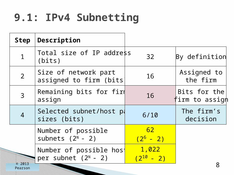
4 6/10
Number of possiblesubnets (2N - 2)
62(26 - 2)
Number of possible hostsper subnet (2N - 2)
1,022(210 - 2)
By definition
Assigned tothe firm
Bits for thefirm to assign
The firm’sdecision

© 2013 Pearson 9
9.1: IPv4 Subnetting
DescriptionStep
32Total size of IP address(bits)
1
Size of network partassigned to firm (bits)
2 8
Remaining bits for firm toassign
3 24
Selected subnet/host partsizes (bits)
4 12/12
Number of possiblesubnets (2N - 2)
4,094(212 - 2)
Number of possible hostsper subnet (2N - 2)
4,094(212 - 2)
By definition
Assigned tothe firm
Bits for thefirm to assign
The firm’sdecision

© 2013 Pearson 10
9.1: IPv4 Subnetting
DescriptionStep
32Total size of IP address(bits)
1
Size of network partassigned to firm (bits)
2 8
Remaining bits for firm toassign
3 24
Selected subnet/host partsizes (bits)
4 8/16
Number of possiblesubnets (2N - 2)
254(28 - 2)
Number of possible hostsper subnet (2N - 2)
65,534(216 - 2)
By definition
Assigned tothe firm
Bits for thefirm to assign
The firm’sdecision

© 2013 Pearson 11
9.1: IPv4 SubnettingDescriptionStep
Size of network partassigned to firm (bits)
2 20
Remaining bits for firm toassign
3 12
Host part size (bits)4 ?
Number of possiblesubnets (2N - 2)
?
Number of possible hostsper subnet (2N - 2)
?
Selected subnet partsize (bits)
Added 4
Exercise
Size of IP address2 32

© 2013 Pearson 12
9.1: IPv4 SubnettingDescriptionStep
Size of network partassigned to firm (bits)
2 20
Remaining bits for firm toassign
3 12
Host part size (bits)4 ?
Number of possiblesubnets (2N - 2)
?
Number of possible hostsper subnet (2N - 2)
?
Selected subnet partsize (bits)
Added 6
Exercise
Size of IP address2 32
IP Subnetting
Network Address Translation (NAT)DNS and DHCP
SNMP
Multiprotocol Label Switching
Securing Internet Transmission
IPv6 Management
© 2013 Pearson 13

NAT
◦ Sends false external source IP addresses and port numbers that are different from internal source IP addresses and port numbers.
◦ For security purposes.
◦ To have many more internal IP addresses than your ISP gives you external IP addresses.
© 2013 Pearson 14
9.2: Network Address Translation (NAT)

© 2013 Pearson 15
9.3: NAT Operation NAT Firewall puts the real source IP address and port
number in the table.

© 2013 Pearson 16
9.3: NAT OperationNAT Firewall replaces the
source IP address and port number of the packet with a false source IP address and port
number.
Adds to table.
© 2013 Pearson 17
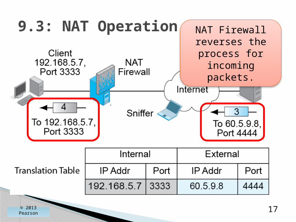
9.3: NAT Operation NAT Firewall reverses the process for incoming packets.

NAT is Transparent to Internal and External Hosts.
◦ The NAT firewall does all the work.
◦ Neither host knows that NAT is taking place.
◦ So there is no need to modify how hosts work.
© 2013 Pearson 18
9.2: Network Address Translation

Security Reasons for Using NAT
◦ External attackers can put sniffers outside the corporation.
◦ Sniffers read IP addresses and port numbers.
◦ Attackers can send attacks to these addresses and port numbers.
◦ With NAT, attackers learn only false external IP addresses. Cannot use thisinformation to attack internal hosts.
© 2013 Pearson 19
9.2: Network Address Translation

Expanding the Number of Available IP Addresses
◦ Companies may receive a limited number of IP addresses from their ISPs.
◦ There are roughly 4,000 possible ephemeral port numbers for each client IP address.
◦ So for each IP address, there can be up to about 4,000 external connections.
◦ If a firm is given 248 IP addresses, there can be roughly one million external connections.
© 2013 Pearson 20
9.2: NAT

Expanding the Number of Available IP Addresses
◦ If each internal device averages several simultaneous external connections, each one will require a different port number.
◦ However, there should not be a problem with this many possible external IP addresses and port numbers.
© 2013 Pearson 21
9.2: NAT
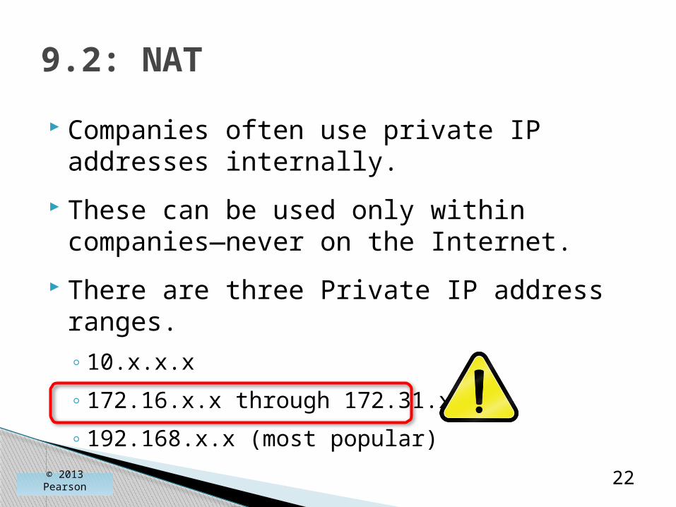
Companies often use private IP addresses internally.
These can be used only within companies—never on the Internet.
There are three Private IP address ranges.◦ 10.x.x.x
◦ 172.16.x.x through 172.31.x.x
◦ 192.168.x.x (most popular)
© 2013 Pearson 22
9.2: NAT

There Are Protocol Problems Caused by NAT
◦ IPsec, VoIP, and other applications have a difficult time with NAT firewall traversal.
◦ They must know the real IP address and port number of the host on the other side of the NAT firewall.
◦ There are NAT firewall traversal techniques, but they must be managed carefully.
© 2013 Pearson 23
9.2: NAT
IP Subnetting
Network Address Translation (NAT)
DNS and DHCP
SNMP
Multiprotocol Label Switching
Securing Internet Transmission
IPv6 Management
© 2013 Pearson 24

The Domain Name System (DNS)
© 2013 Pearson 25
© 2013 Pearson 26
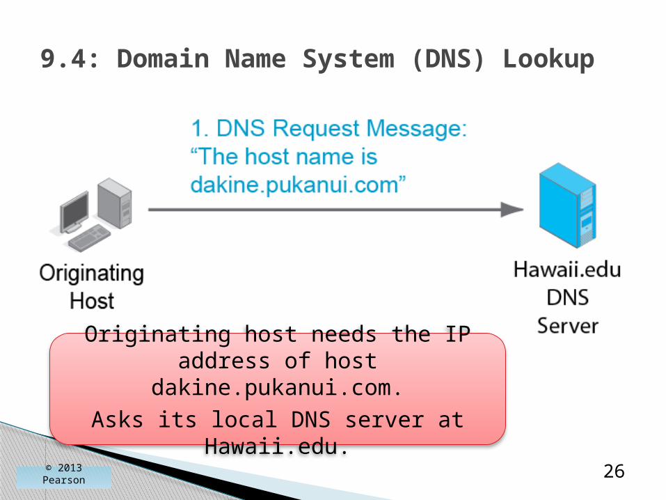
9.4: Domain Name System (DNS) Lookup
Originating host needs the IP address of host dakine.pukanui.com.Asks its local DNS server at
Hawaii.edu.

© 2013 Pearson 27
9.4: Domain Name System (DNS) Lookup

© 2013 Pearson 28
9.4: Domain Name System (DNS) Lookup
Sends response to local DNS server,
not the client host.

© 2013 Pearson 29
9.4: Domain Name System (DNS) Lookup
Note that the local DNS server always sends back the response
message.
© 2013 Pearson 30
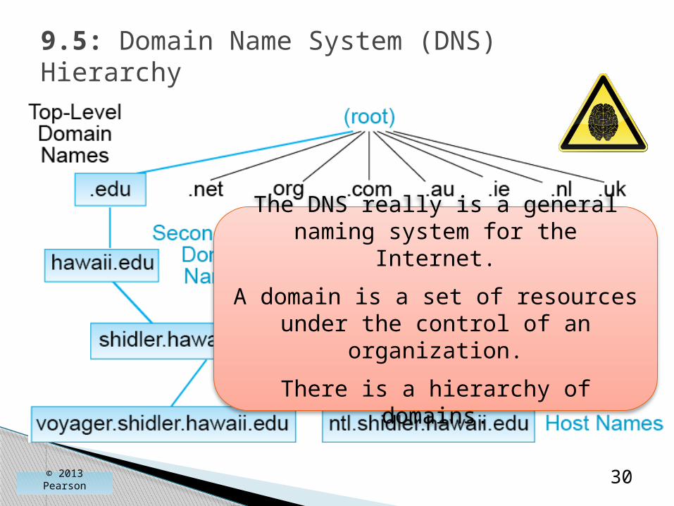
9.5: Domain Name System (DNS) Hierarchy
The DNS really is a general naming system for the Internet.
A domain is a set of resources under the control of an
organization.
There is a hierarchy of domains.

© 2013 Pearson 31
9.5: Domain Name System (DNS) Hierarchy
The root is all domains.There are 13 DNS root servers.

© 2013 Pearson 32
9.5: Domain Name System (DNS) Hierarchy
There are two kinds of top-level domains.
Generic top-level domains indicate organization type (.com, .edu, .gov, etc.).
Country top-level domains are specific to a country (.UK, .CA, .CH, etc.).

Traditionally, generic top-level domains were strongly limited in number.
There have been a few additions over the year, such as .museum, .name, and .co.
As of 2013, any individual or company can propose to administer a generic top-level domain.
9.5: Domain Name System (DNS) Hierarchy
© 2013 Pearson 33

© 2013 Pearson 34
9.5: Domain Name System (DNS) Hierarchy
Companies want second-level domain names.
(Microsoft.com, apple.com, panko.com, etc.).
Competition for these names is fierce.
© 2013 Pearson 35
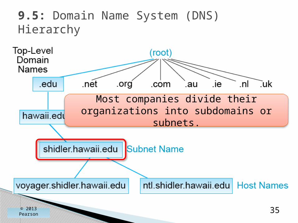
9.5: Domain Name System (DNS) Hierarchy
Most companies divide their organizations into subdomains or subnets.

© 2013 Pearson 36
9.5: Domain Name System (DNS) Hierarchy
At the bottom of the hierarchy are individual hosts.

The Dynamic Host Configuration Protocol (DHCP)
© 2013 Pearson 37
© 2013 Pearson 38
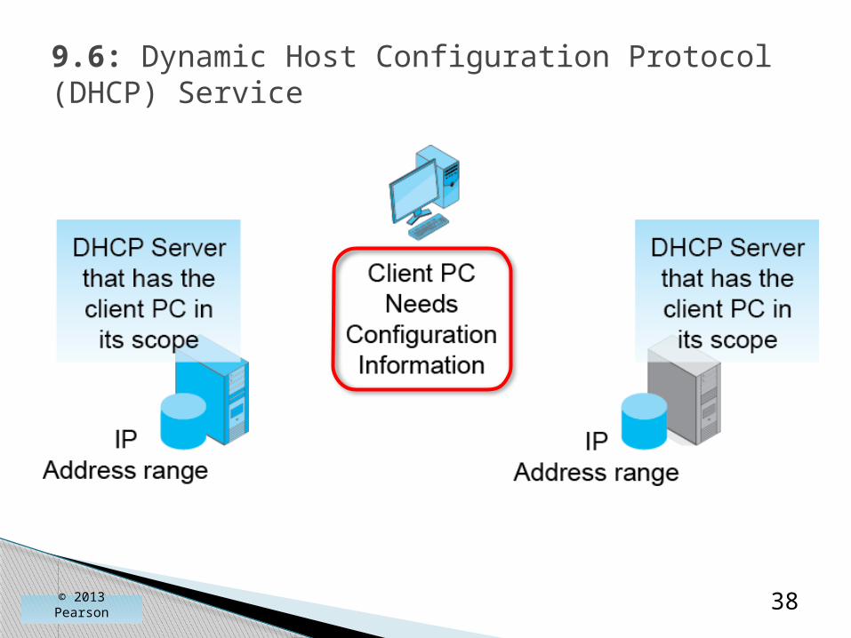
9.6: Dynamic Host Configuration Protocol (DHCP) Service

© 2013 Pearson 39
9.6: Dynamic Host Configuration Protocol (DHCP) Service
© 2013 Pearson 40
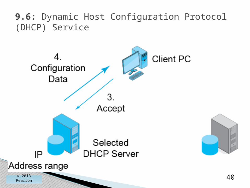
9.6: Dynamic Host Configuration Protocol (DHCP) Service
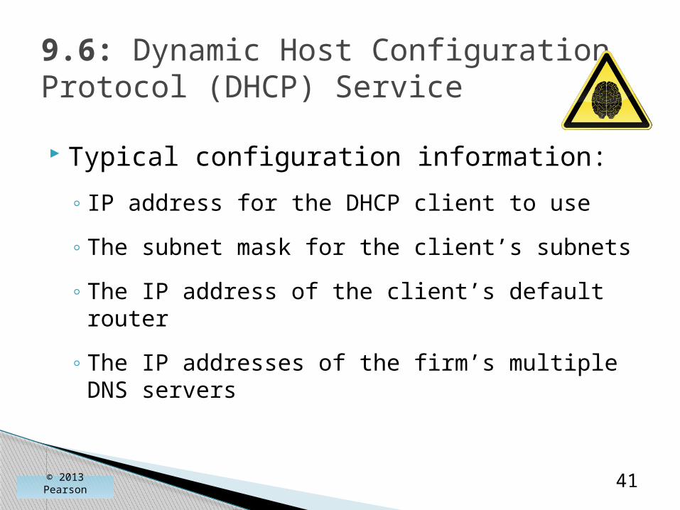
Typical configuration information:
◦ IP address for the DHCP client to use
◦ The subnet mask for the client’s subnets
◦ The IP address of the client’s default router
◦ The IP addresses of the firm’s multiple DNS servers
© 2013 Pearson 41
9.6: Dynamic Host Configuration Protocol (DHCP) Service

The two are often confused because both give a client PC an IP address.
◦ DHCP gives a client PC its own dynamic IP address.
◦ DNS gives a client PC the IP address of a host the client wishes to send packets to.
DNS versus DHCP
© 2013 Pearson 42

IP Subnetting
Network Address Translation (NAT)
DNS and DHCP
SNMP
Multiprotocol Label Switching
Securing Internet Transmission
IPv6 Management
© 2013 Pearson 43

Core Elements (from Chapter 4)◦ Manager program
◦ Managed device
◦ Agents (communicate with the manager on behalf of the managed device)
© 2013 Pearson 44
9.7: Simple Network Management Protocol (SNMP)
ManagedDevices
Agents
Manager

Core Elements (from Chapter 4)◦ Management information base (MIB).
◦ Stores the retrieved information.
◦ “MIB” can refer to either the database on the manager or to the database schema.
© 2013 Pearson 45
9.7: Simple Network Management Protocol (SNMP)
Manager MIB
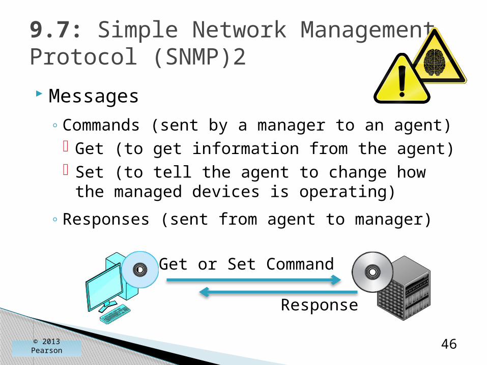
Messages◦ Commands (sent by a manager to an agent)
Get (to get information from the agent) Set (to tell the agent to change how the
managed devices is operating)
◦ Responses (sent from agent to manager)
© 2013 Pearson 46
9.7: Simple Network Management Protocol (SNMP)2
Get or Set Command
Response

Messages
◦ Traps (alarms sent by agents).
◦ SNMP uses UDP at the transport layer to minimize the burden on the network.
© 2013 Pearson 47
9.7: Simple Network Management Protocol (SNMP)
Trap

Set Commands◦ Dangerous if used by attackers.
◦ Many firms disable Set to thwart such attacks.
◦ However, they give up the ability to manage remote resources without travel.
◦ SNMPv1: community string shared by the manager and all devices (poor).
◦ SNMPv3: each manager–agent pair has a different password (good).
© 2013 Pearson 48
9.7: Simple Network Management Protocol (SNMP)

Objects (Figure 9-8)◦ Specific pieces of information
◦ Number of rows in the routing table
◦ Number of discards caused by lack of resources (indicates a need for an upgrade)
© 2013 Pearson 49
9.7: Simple Network Management Protocol (SNMP)
Objects are NOT managed devices!
Objects are specific pieces of data about a managed device.

Categories of Objects◦System objects (one set per managed device)
System name
System description
System contact person
System uptime (since last reboot)
© 2013 Pearson 50
9.7: Simple Network Management Protocol (SNMP)

Categories of Objects◦ IP objects (one set per managed device)
Forwarding (for routers), Yes if forwarding (routing), No if not
Cause of resource limitations
Number of rows in routing table
Rows discarded because of lack of space
Individual row data
© 2013 Pearson 51
9.8: SNMP Object Model

Categories of Objects◦ TCP objects (one set per managed device)
Retransmission time
Maximum number of TCP connections allowed
Opens/failed connections/resets
Segments sent
Segments retransmitted
Errors in incoming segments
Data on individual connections (sockets, states)
© 2013 Pearson 52
9.8: SNMP Object Model

Categories of Objects
◦UDP objects (one set per host)
Traffic statistics
◦ ICMP objects (one set per host)
Number of ICMP errors of various types
© 2013 Pearson 53
9.8: SNMP Object Model

Categories of Objects◦ One set per managed device:
System IP TCP UDP ICMP
Interface objects: one set per interface (port)
© 2013 Pearson 54
9.8: SNMP Object Model

Categories of Objects◦ Interface objects (one set per interface)
Type (e.g., 69 is 100Base-FX; 71 is 802.11)
Status: up/down/testing
Speed
Errors: discards, unknown protocols, and so on
© 2013 Pearson 55
9.8: SNMP Object Model

SNMP Manager program collects data.◦ Places it in the MIB.
Visualization Program.◦ The administrator’s interface to the MIB.
◦ Helps the administrator visualize patterns in the MIB data.
◦ Can order the SNMP Manager to collect certain data or to send set commands to change the configurations of managed devices.
© 2013 Pearson 56
9.7: SNMP

User Functionality
◦ Reports, diagnostics tools, and so on, are very important.
◦ They are not built into the standard.
◦ They are added by network visualization program vendors.
◦ Critical in selection of a network management vendor.
© 2013 Pearson 57
9.7: Simple Network Management Protocol (SNMP)

IP Subnetting
Network Address Translation (NAT)
DNS and DHCP
SNMP
Multiprotocol Label SwitchingSecuring Internet Transmission
IPv6 Management
© 2013 Pearson 58
Routers route each packet individually, going through the three steps we saw in the last chapter.◦ Even if the next packet is going to the same
destination IP address, the router will go through all three steps.
◦ This consumes a great deal of processing power per packet.
◦ This makes traditional routing expensive.
© 2013 Pearson 59
Multiprotocol Label Switching

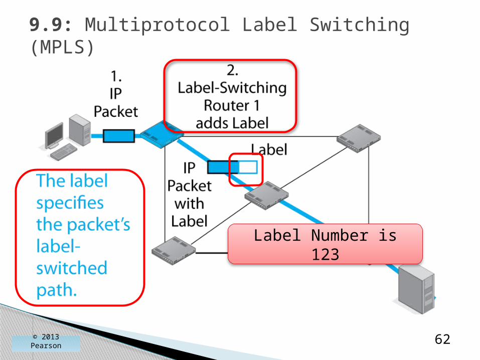
MPLS addresses this issue.◦ Routers identify the best route for a range of IP
addresses before sending data.
◦ That route is given a label number.
◦ Each packet in a stream gets a label with this label number.
◦ Routers do only a quick table lookup per packet.
◦ Table lookups require little processing power.
◦ So multiprotocol label switching is much less expensive than traditional routing.
© 2013 Pearson 60
Multiprotocol Label Switching

© 2013 Pearson 61
9.9: Multiprotocol Label Switching (MPLS)
© 2013 Pearson 62
9.9: Multiprotocol Label Switching (MPLS)
Label Number is 123

Label sits between the frame header and the IP packet header.
9.9: MPLS
© 2013 Pearson 63
IP PacketHeader
MPLS Label Frame Header

© 2013 Pearson 64
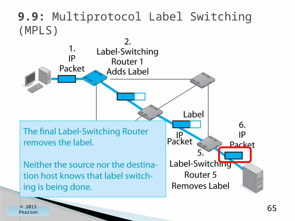
9.9: Multiprotocol Label Switching (MPLS)
Router 3 sends the packet out
through Interface 1
© 2013 Pearson 65
9.9: Multiprotocol Label Switching (MPLS)

© 2013 Pearson 66
9.9: Multiprotocol Label Switching (MPLS)

Implementing MPLS is difficult.
Many individual ISPs and corporations do it.
Some individual ISPs have “peering” arrangements with other individual ISPs to do it.
There is no general way to move MPLS out to all ISPs and organizations.
9.9: Multiprotocol Label Switching (MPLS)
© 2013 Pearson 67

IP Subnetting
Network Address Translation (NAT)
DNS and DHCP
SNMP
Multiprotocol Label Switching
Securing Internet TransmissionIPv6 Management
© 2013 Pearson 68

Security was not addressed in the initial design of TCP/IP.
Jon Postel, who edited the main Internet RFCs, explained to the first author, “It just wasn’t a problem then, and we were stretched thin.”
Today, firms are adding security to their transmissions through IPsec VPNs.
Securing Internet Transmission
© 2013 Pearson 69

A virtual private network (VPN) is a cryptographically secured transmission path through an untrusted environment.◦ The Internet◦ A wireless network◦ Communication in a foreign country
Like having your own private network in terms of security.◦ However, not a real private network.
9.10: Virtual Private Network
© 2013 Pearson 70

IPsec VPNs
© 2013 Pearson 71
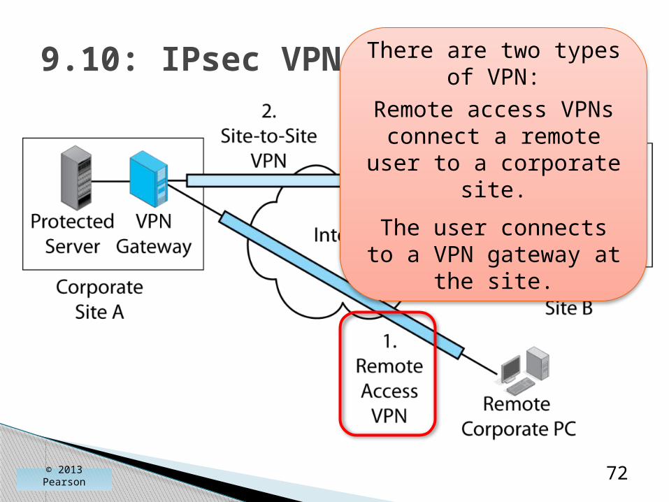
9.10: IPsec VPNs
© 2013 Pearson 72
There are two types of VPN:
Remote access VPNs connect a remote user
to a corporate site.
The user connects to a VPN gateway at the
site.

9.10: IPsec VPNs
© 2013 Pearson 73
There are two types of VPNs:Site-to-site VPNs protect all traffic
traveling between two sites.Each site has a gateway to encrypt
outgoing traffic and decrypt incoming traffic.
IPsec has two modes (ways) of operating:◦ Transport mode
◦ Tunnel mode
Each mode has strengths and weaknesses.
Selecting an IPsec mode option is very important to security.
9.11: IPsec in Transport and Tunnel Modes
© 2013 Pearson 74
© 2013 Pearson 75
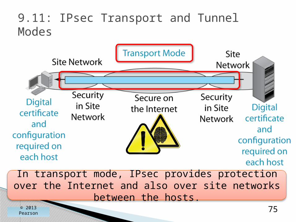
9.11: IPsec Transport and Tunnel Modes
In transport mode, IPsec provides protection over the Internet and also over site networks between the
hosts.

© 2013 Pearson 76
9.11: IPsec Transport and Tunnel Modes
Transport mode requires a digital certificate and configuration work on each host.
This is expensive.
© 2013 Pearson 77
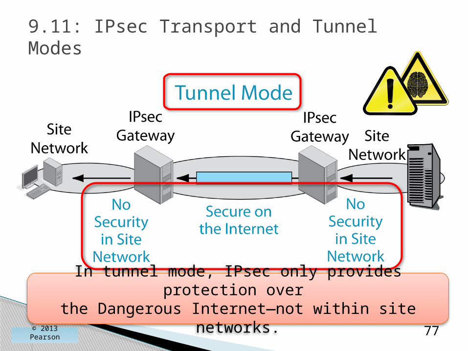
9.11: IPsec Transport and Tunnel Modes
In tunnel mode, IPsec only provides protection over
the Dangerous Internet—not within site networks.
© 2013 Pearson 78
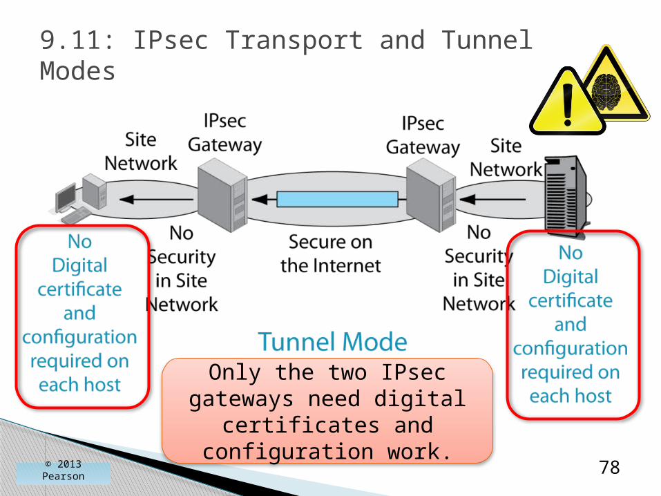
9.11: IPsec Transport and Tunnel Modes
Only the two IPsec gateways need digital
certificates and configuration work.
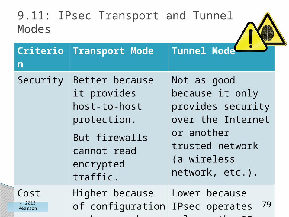
Criterion Transport Mode Tunnel Mode
Security Better because it provides host-to-host protection.
But firewalls cannot read encrypted traffic.
Not as good because it only provides security over the Internet or another trusted network (a wireless network, etc.).
Cost Higher because of configuration work on each host.
Lower because IPsec operates only on the IPsec gateway .
© 2013 Pearson 79
9.11: IPsec Transport and Tunnel Modes

© 2013 Pearson 80
9.12: IPsec Security Associations and Policy Servers

© 2013 Pearson 81
9.12: IPsec Security Associations and Policy Servers

SSL/TLS VPNs
82© 2013 Pearson

Purpose
◦ To provide a secure connection between a client browser and a webserver application on a webserver host
◦ Use is indicated by https:// in the URL
◦ Very widely used
9.13: SSL/TLS VPNs (Study Figure)
© 2013 Pearson 83

Origin
◦ Created by Netscape as SSL.
◦ IETF took over the standard.
◦ IETF changed the standard’s name to Transport Layer Security (TLS).
◦ We refer to the standard, generically, as SSL/TLS.
9.13: SSL/TLS VPNs (Study Figure)
© 2013 Pearson 84

Attraction of SSL/TLS
◦ Universally supported by browsers and webserver applications.
◦ So no added cost on the client to use it!
◦ No extra software on the server is needed, but SSL/TLS must be configured, which usually is simple.
9.13: SSL/TLS VPNs (Study Figure)
© 2013 Pearson 85
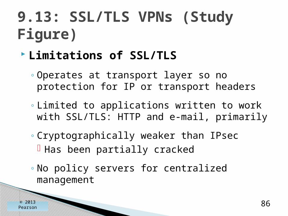
Limitations of SSL/TLS
◦ Operates at transport layer so no protection for IP or transport headers
◦ Limited to applications written to work with SSL/TLS: HTTP and e-mail, primarily
◦ Cryptographically weaker than IPsec Has been partially cracked
◦ No policy servers for centralized management
9.13: SSL/TLS VPNs (Study Figure)
© 2013 Pearson 86

Overall◦ Decent quality, cheap, and easy security
◦ Limited in how it can be used and managed
Comparison with IPsec◦ IPsec is more complex and so more expensive.
◦ Can be used for all types of VPNs.
◦ Can be managed well.
◦ Gold standard in TCP/IP security.
9.13: SSL/TLS VPNs (Study Figure)
© 2013 Pearson 87

IP Subnetting
Network Address Translation (NAT)
DNS and DHCP
SNMP
Multiprotocol Label Switching
Securing Internet Transmission
IPv6 Management
© 2013 Pearson 88
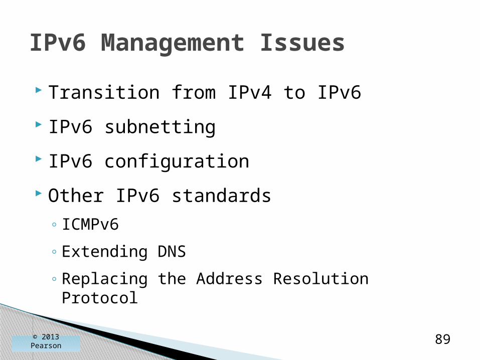
Transition from IPv4 to IPv6
IPv6 subnetting
IPv6 configuration
Other IPv6 standards◦ ICMPv6
◦ Extending DNS
◦ Replacing the Address Resolution Protocol
IPv6 Management Issues
© 2013 Pearson 89

Must transition all clients, routers, firewalls, and so on
The IETF’s plan◦ No backward compatibility
◦ Instead, add both IPv4 and IPv6 protocol stacks at the internet layer to all new devices
◦ As soon as most devices have IPv6 protocol stacks, configure the devices and add IPv6 support to IPv4 support
◦ Eventually, turn off IPv4 support
Transitioning to IPv6
© 2013 Pearson 90

Problems and reactions◦ IPv6 offered few benefits, so most companies
ignored IPv6.
◦ The shortage of IPv4 addresses was handled (intelligently) through NAT.
◦ But now, IPv4 addresses are gone.
◦ Now some clients, such as mobile phones, only have IPv6 stacks at the protocol layer.
◦ To serve them, companies are rushing to turn on and configure IPv6 support.
Transitioning to IPv6
© 2013 Pearson 91
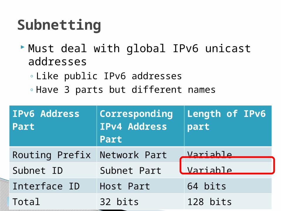
Must deal with global IPv6 unicast addresses◦ Like public IPv6 addresses◦ Have 3 parts but different names
Subnetting
© 2013 Pearson 92
IPv6 Address Part
Corresponding IPv4 Address Part
Length of IPv6 part
Routing Prefix Network Part Variable
Subnet ID Subnet Part Variable
Interface ID Host Part 64 bits
Total 32 bits 128 bits

9.15: Global Unicast Addresses in IPv6
© 2013 Pearson 93
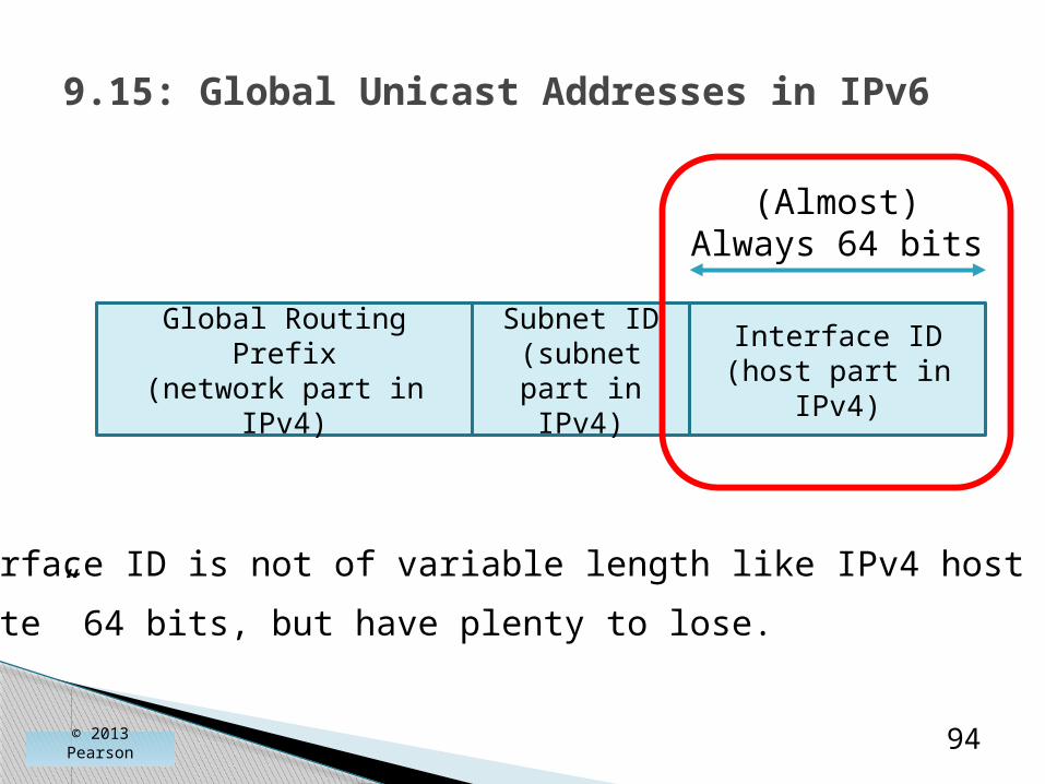
Global Routing Prefix(network part in IPv4)
Subnet ID(subnet part
in IPv4)
Interface ID(host part in IPv4)
9.15: Global Unicast Addresses in IPv6
© 2013 Pearson 94
Global Routing Prefix(network part in IPv4)
Subnet ID(subnet part
in IPv4)
Interface ID(host part in IPv4)
(Almost)Always 64 bits
Interface ID is not of variable length like IPv4 host parts.
“Waste” 64 bits, but have plenty to lose.

9.15: Global Unicast Addresses in IPv6
© 2013 Pearson 95
Global Routing Prefix(network part in IPv4)
Subnet ID(subnet part
in IPv4
Interface ID(host part in IPv4)
(Almost)Always 64 bits
m bits n bits
64 bits
m + n = 64

An IP address registrar gives you a 32-bit global routing prefix.
How long is your subnet ID?
How many subnets can you have (approximately)?
Many companies have a two-layer hierarchy of subnets, using some bits for the main subnet and remaining bits for sub-subnets.
9.15: Subnetting
© 2013 Pearson 96
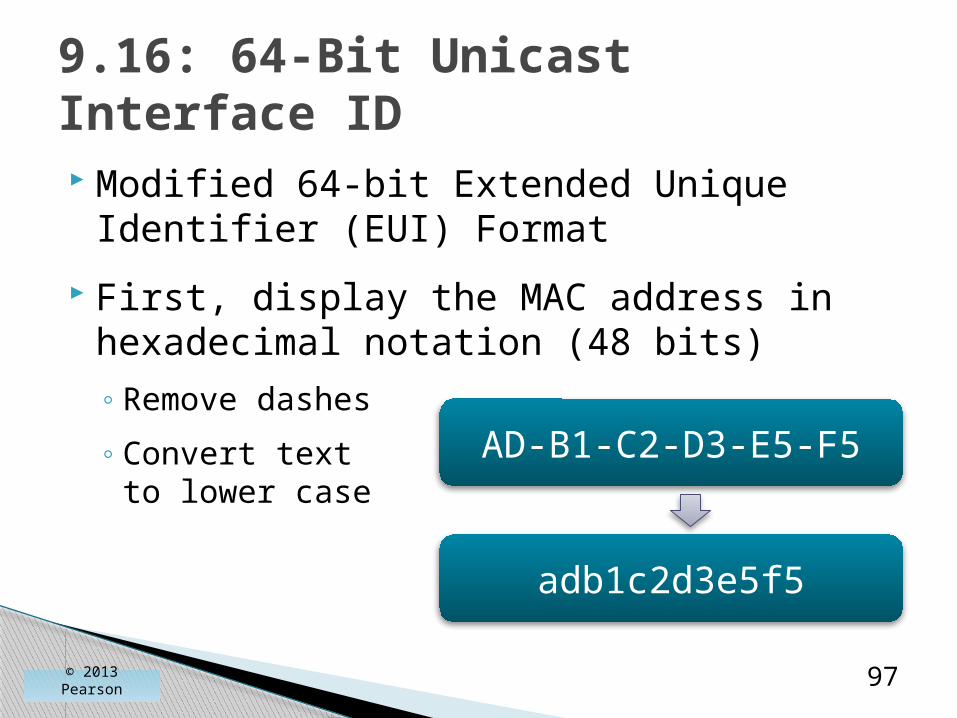
Modified 64-bit Extended Unique Identifier (EUI) Format
First, display the MAC address in hexadecimal notation (48 bits)◦ Remove dashes
◦ Convert text to lower case
9.16: 64-Bit Unicast Interface ID
© 2013 Pearson 97
AD-B1-C2-D3-E5-F5
adb1c2d3e5f5

Second, divide the address in half
Insert fffe in the middle
This creates a 64-bit address
9.16: 64-Bit Unicast Interface ID
© 2013 Pearson 98
adb1c2 fffe d3e5f5
adb1c2fffed3e5f5

Third, in the second nibble (d) (1101)
Invert the second bit from the right (1111) (f)
This is called Modified 64-bit EUI
9.16: 64-Bit Unicast Interface ID
© 2013 Pearson 99
adb1c2fffed3e5f5
afb1c2fffed3e5f5

1. Begin with MAC in hexadecimal notation
2. Divide the 48 bits into 2 halves of 24 bits
3. Insert fffe between the two halves
4. Place into four-hex groups separated by colons
5. Flip the second-least significant bit in the first octet
9.16: 64-Bit Interface ID Recap
© 2013 Pearson 100
Hosts must be configured with IP addresses
IPv4 uses DHCP
IPv6 offers two configuration mechanisms◦ DHCPv6 (very similar to IPv4)
◦ Stateless autoconfiguration, which does not use a DHCPv6 server
◦ Not available in IPv4
9.17: IPv6 Stateless Autoconfiguration
© 2013 Pearson 101

Stateless Autoconfiguration
◦ The client configures itself, without using a DHCPv6 server.
◦ First, the client creates a link-local IPv6 address.
◦ Second, the client creates a global unicast IPv6 address.
9.17: IPv6 Stateless Autoconfiguration
© 2013 Pearson 102

Creating the Link-Local IPv6 Addresses
◦ Link-local IPv6 addresses can be used only within a single network (wireless or switched wired).
◦ If the client does not need a global IP address, the autoconfiguration process can stop here.
9.17: IPv6 Stateless Autoconfiguration
© 2013 Pearson 103
Creating the Link-Local Address
◦ First create a 64-bit interface ID using the MAC address of the client.
◦ Add a routing prefix 111 1110 10 followed by 56 bits of zeroes.
◦ This is the link-local IP address: fe80::x, where x is the octets of the EUI-64.
9.17: IPv6 Stateless Autoconfiguration
© 2013 Pearson 104
Testing the Link-Local Address
◦ Another host may be using this address.
◦ So the client uses the ICMPv6 neighbor discovery protocol to ask if any other host in the single network is using this address.
◦ If none reply, the client may use this address within its single network.
9.17: IPv6 Stateless Autoconfiguration
© 2013 Pearson 105

Creating the Global Unicast IPv6 Address
◦ Needed for communication over the Internet.
◦ Begin with the link-local address.
◦ Keep the interface ID but get a new routing prefix and subnet ID.
◦ Client sends an ICMPv6 router solicitation message to the address FFF02::1, which all routers listen for.
9.17: IPv6 Stateless Autoconfiguration
© 2013 Pearson 106
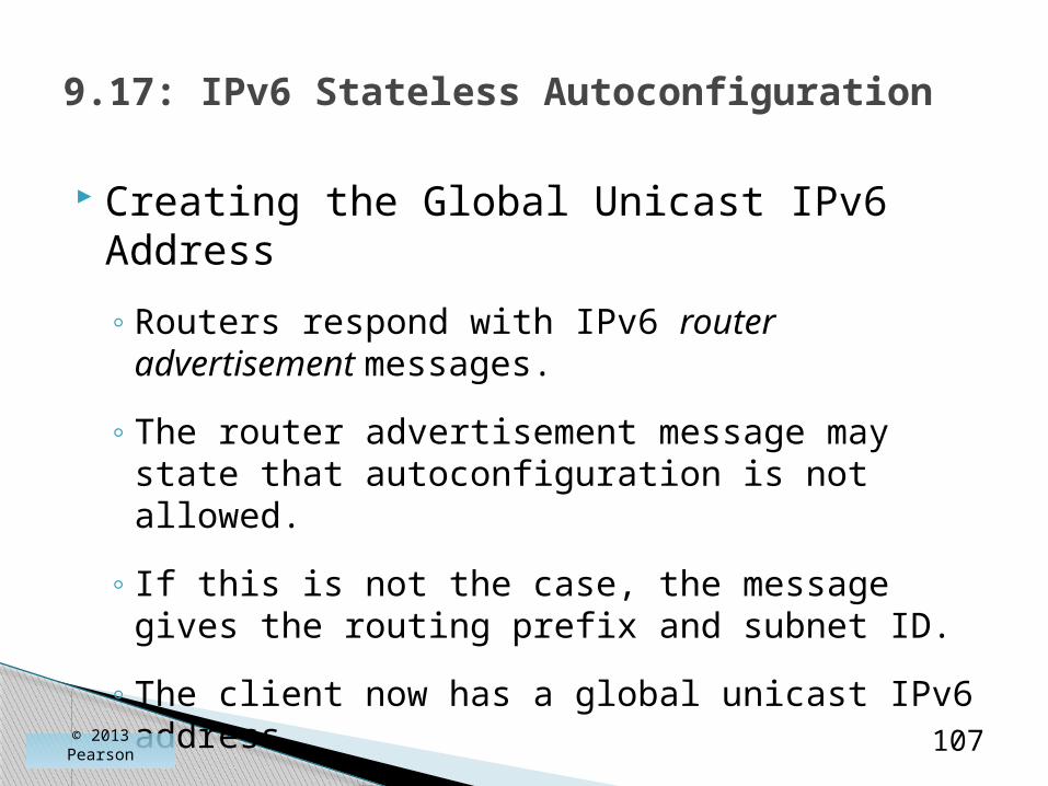
Creating the Global Unicast IPv6 Address
◦ Routers respond with IPv6 router advertisement messages.
◦ The router advertisement message may state that autoconfiguration is not allowed.
◦ If this is not the case, the message gives the routing prefix and subnet ID.
◦ The client now has a global unicast IPv6 address.
9.17: IPv6 Stateless Autoconfiguration
© 2013 Pearson 107

Limits
◦ More limited than traditional DHCP autoconfiguration.
◦ At a minimum, router advertisement messages give only a routing prefix and subnet ID.
◦ Of course, the packet containing the router advertisement message gives the IPv6 address of the router, which becomes the default router.
9.17: IPv6 Stateless Autoconfiguration
© 2013 Pearson 108

Uses
◦ How can a client get other IPv6 configuration information?
◦ If a client is a dual-stack client, the IPv4 stack can obtain full configuration information, which the IPv6 stack can use.
9.17: IPv6 Stateless Autoconfiguration
© 2013 Pearson 109

Uses
◦ If the client is not a dual-stack client, it needs at least one more piece of configuration information—the IPv6 addresses of DNS servers.
◦ The IETF has extended router advertisement messages to provide the IPv6 addresses of DNS servers.
◦ However, this is only an option.
9.17: IPv6 Stateless Autoconfiguration
© 2013 Pearson 110

Known Security Weaknesses
◦ An attacker might create an address that does not use its proper EUI-64.
◦ An attacker may create an address that uses the EUI-64 of another host to impersonate it.
◦ Several operations can be used to create flooding denial-of-service attacks.
9.17: IPv6 Stateless Autoconfiguration
© 2013 Pearson 111

IPv6 Address Renumbering
◦ Stateless autoconfiguration may be used to renumber all IP addresses in a firm automatically, changing subnet IDs and even routing prefixes.
9.17: IPv6 Stateless Autoconfiguration
© 2013 Pearson 112
ICMPv6◦ Many new types were created for neighbor
discovery, stateless autoconfiguration, and so on.
9.18: Other IPv6 Standards
© 2013 Pearson 113

Domain Name System (DNS)◦ The DNS information for a host is contained in
several records.
◦ DNS A Record. The A record contains the IPv4 address for the target host.
◦ DNS AAAA Record. For IPv6 addresses, a new address record had to be added.
IPv6 addresses are four times as long as IPv4 addresses, so the added record is called the AAAA record.
9.18: Other IPv6 Standards
© 2013 Pearson 114
Address Resolution Protocol (ARP) Messages
◦ In IPv6, handled by the ICMP neighbor discovery protocol, which has two message types.
◦ Neighbor solicitation messages ask host to respond.
◦ Neighbor advertisement messages give the host’s data link address.
◦ There is no ARPv6.
9.18: Other IPv6 Standards
© 2013 Pearson 115

IP SubnettingNetwork Address Translation (NAT)DNS and DHCP
SNMP
Multiprotocol Label Switching
Securing Internet Transmission
IPv6 Management
© 2013 Pearson 116
Where We’ve Been
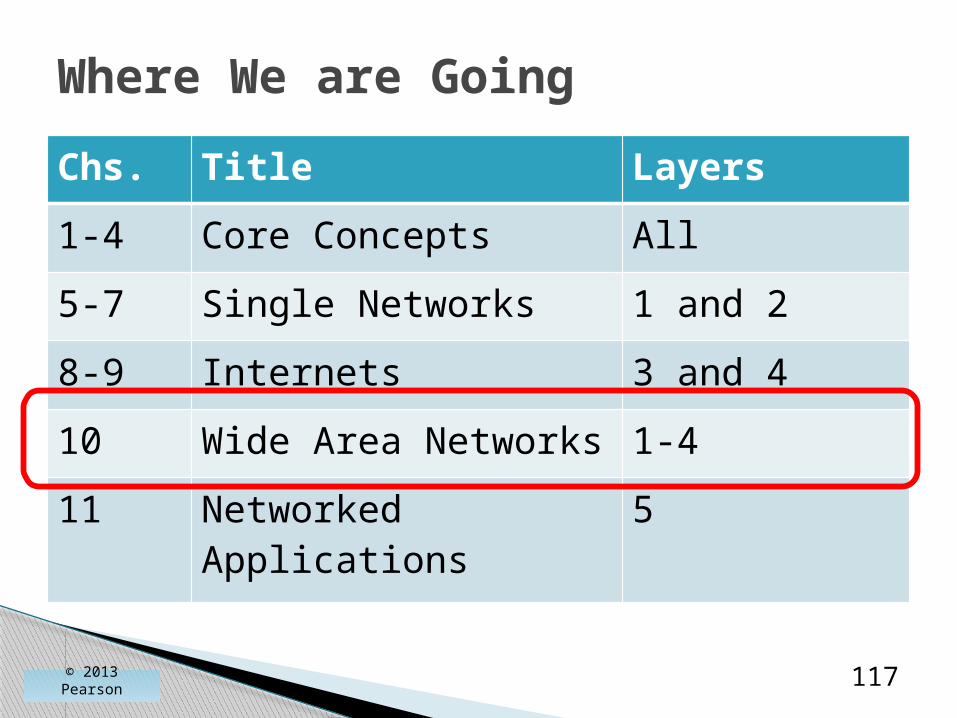
Chs. Title Layers
1-4 Core Concepts All
5-7 Single Networks 1 and 2
8-9 Internets 3 and 4
10 Wide Area Networks 1-4
11 Networked Applications
5
Where We are Going
© 2013 Pearson 117
118© 2013 Pearson