chapter 9 discrete control using programmable logic...
TRANSCRIPT
Discrete Control Using Programmable Logic Controllers
Chapter 9
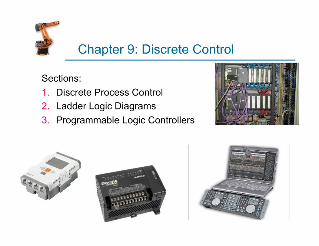
Chapter 9: Discrete Control
Sections: 1. Discrete Process Control 2. Ladder Logic Diagrams 3. Programmable Logic Controllers
Sec 9.1: Discrete Process Control
§ Continuous Control: deals with controlling continuous variables or parameters in the system.
§ Discrete Control: Control systems that operate on parameters and variables that change at discrete moments in time or at discrete events, § usually binary (0 or 1, off or on, open or closed,
etc.) § Called also: switching systems.
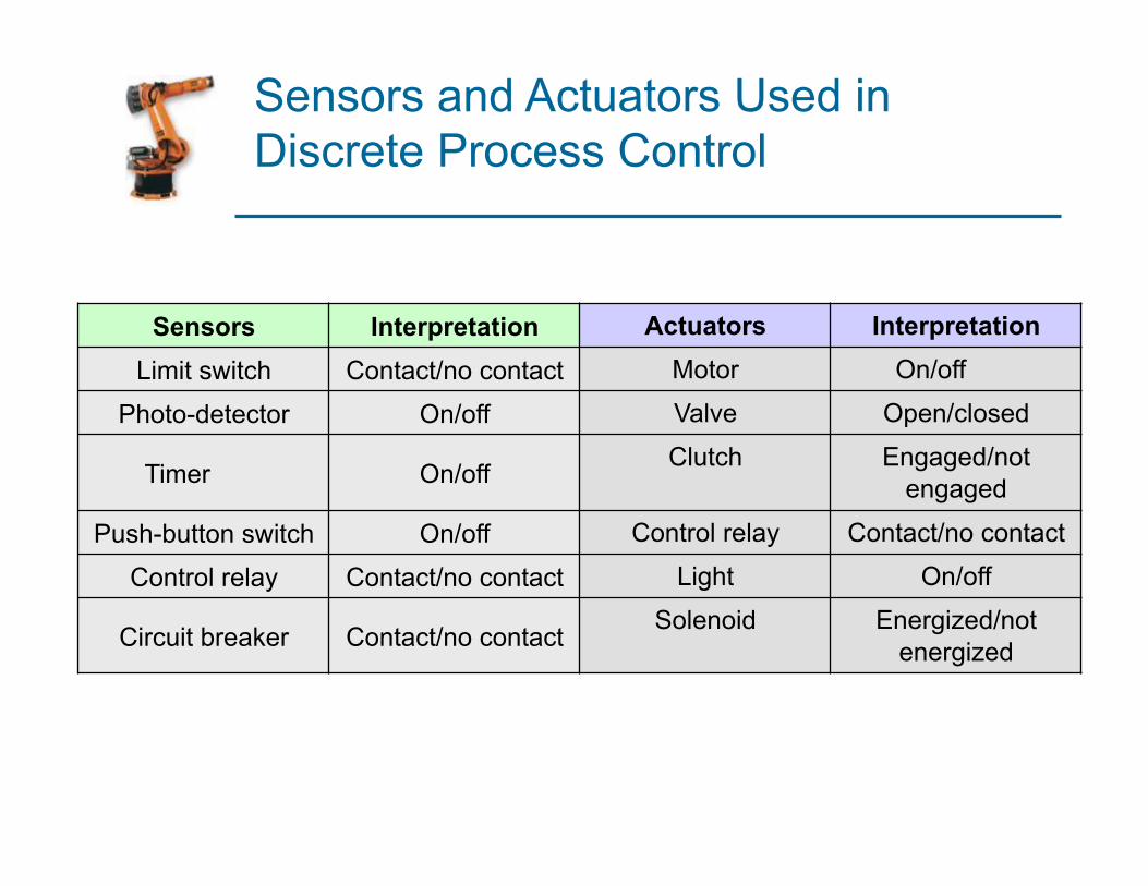
Sensors and Actuators Used in Discrete Process Control
Sensors Interpretation Actuators Interpretation Limit switch Contact/no contact Motor On/off
Photo-detector On/off Valve Open/closed
Timer On/off Clutch Engaged/not engaged
Push-button switch On/off Control relay Contact/no contact
Control relay Contact/no contact Light On/off
Circuit breaker Contact/no contact Solenoid Energized/not energized
Categories of Discrete Control
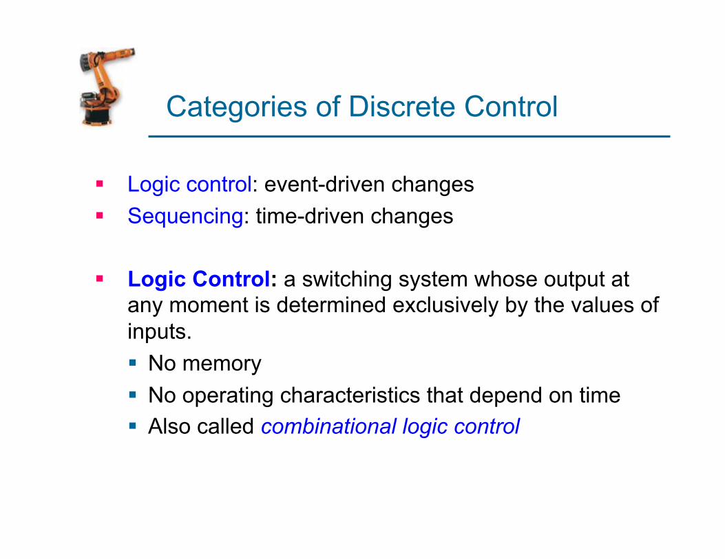
§ Logic control: event-driven changes § Sequencing: time-driven changes
§ Logic Control: a switching system whose output at any moment is determined exclusively by the values of inputs. § No memory § No operating characteristics that depend on time § Also called combinational logic control
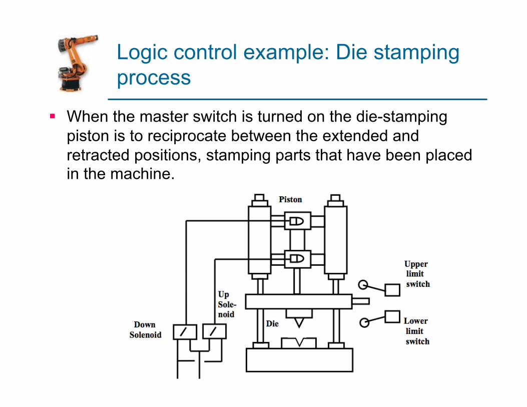
Logic control example: Die stamping process
§ When the master switch is turned on the die-stamping piston is to reciprocate between the extended and retracted positions, stamping parts that have been placed in the machine.
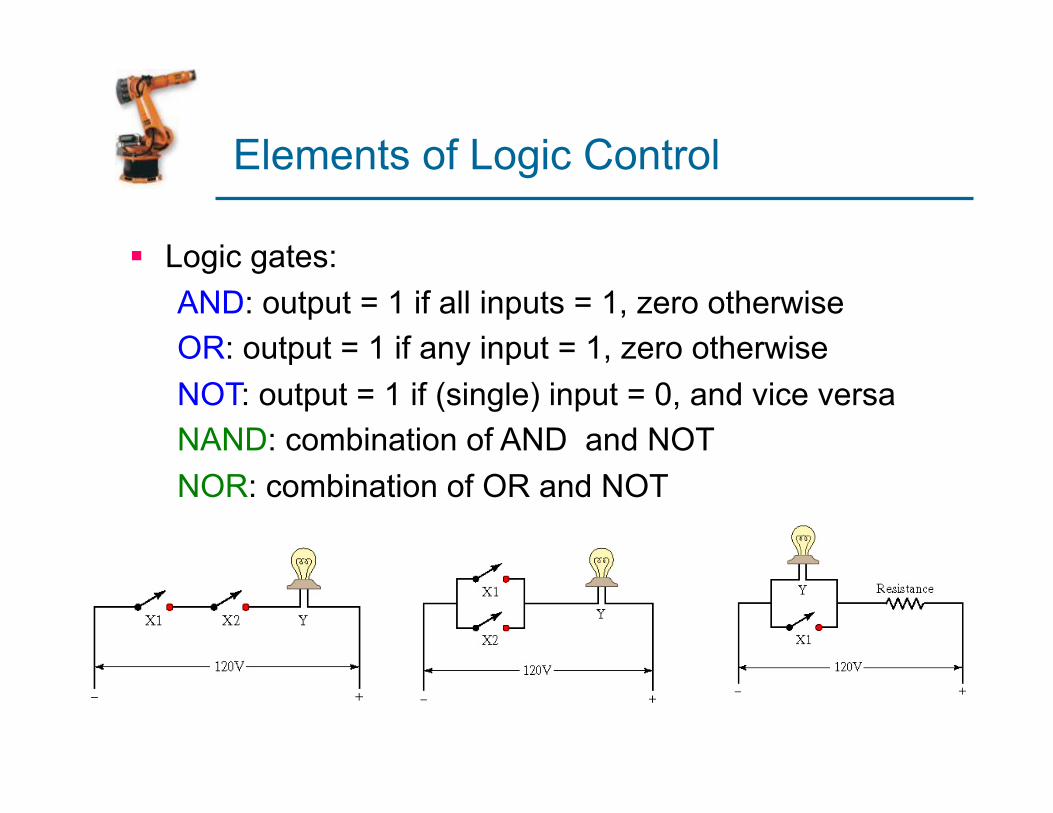
Elements of Logic Control
§ Logic gates: AND: output = 1 if all inputs = 1, zero otherwise OR: output = 1 if any input = 1, zero otherwise NOT: output = 1 if (single) input = 0, and vice versa NAND: combination of AND and NOT NOR: combination of OR and NOT

Boolean Algebra & Truth Tables
AND function is expressed as Y = X1*X2
OR function is expressed as Y = X1+X2
NOT function is expressed as Y=X1
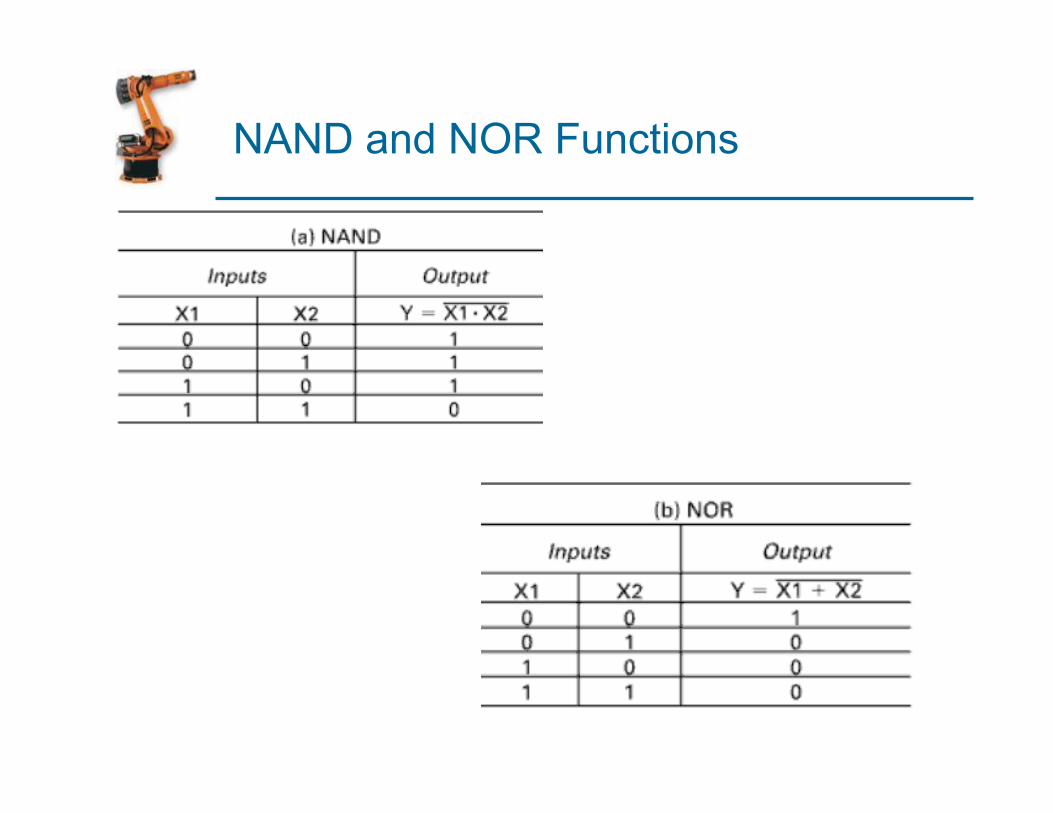
NAND and NOR Functions
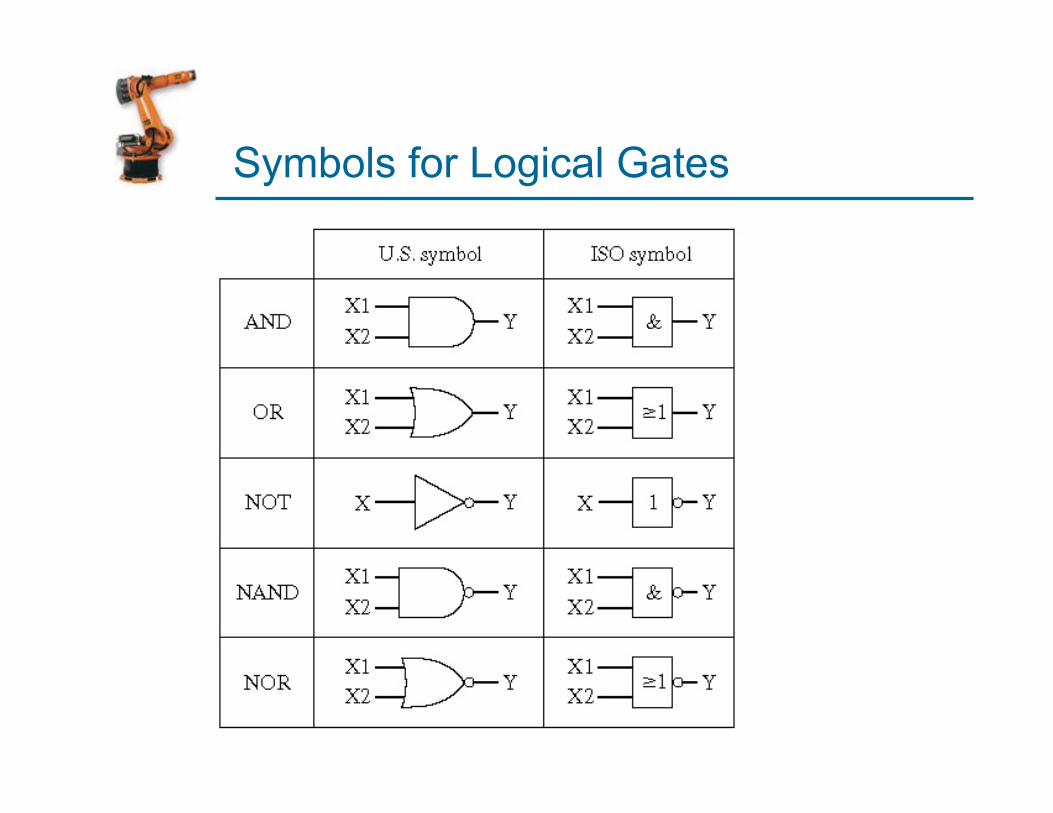
Symbols for Logical Gates
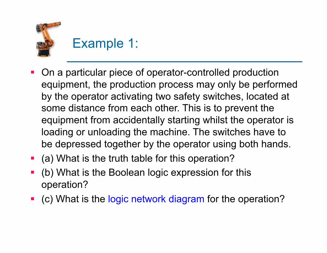
Example 1:
§ On a particular piece of operator-controlled production equipment, the production process may only be performed by the operator activating two safety switches, located at some distance from each other. This is to prevent the equipment from accidentally starting whilst the operator is loading or unloading the machine. The switches have to be depressed together by the operator using both hands.
§ (a) What is the truth table for this operation? § (b) What is the Boolean logic expression for this
operation? § (c) What is the logic network diagram for the operation?
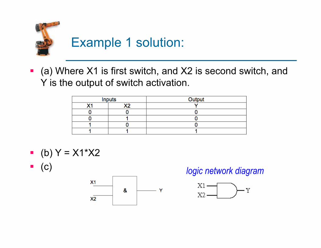
Example 1 solution:
§ (a) Where X1 is first switch, and X2 is second switch, and Y is the output of switch activation.
§ (b) Y = X1*X2 § (c) logic network diagram
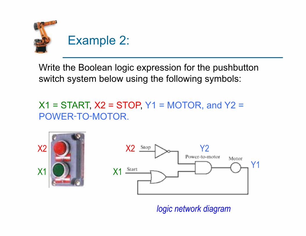
Example 2:
Write the Boolean logic expression for the pushbutton switch system below using the following symbols:
X1 = START, X2 = STOP, Y1 = MOTOR, and Y2 =
POWER‑TO‑MOTOR.
X1
X2 Y2
Y1
X2
X1
logic network diagram
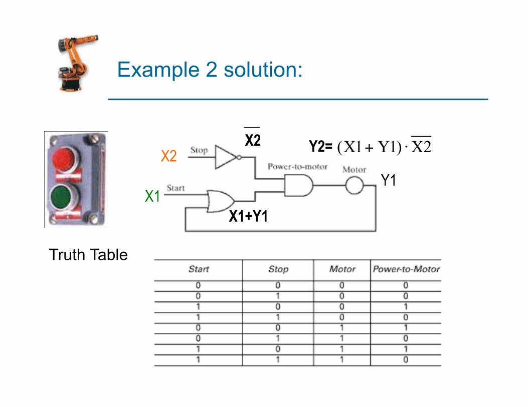
Example 2 solution:
Truth Table
X1
X2 Y2=
Y1
X2
X1+Y1
Sequencing
A switching system that uses internal timing devices to determine when to initiate changes in output variables
§ Examples: Washing machines, dryers, dishwashers, Traffic light.
Sequencing
§ Outputs are usually generated “open loop” § No feedback that control function is executed
§ Sequence of output signals is usually cyclical, as in a high production work cycle § The signals occur in the same repeated pattern within
each regular cycle
§ Common sequencing devices: § Timer – output switches on/off at preset times § Counter – counts electrical pulses and stores them
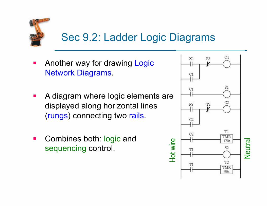
Sec 9.2: Ladder Logic Diagrams
§ Another way for drawing Logic Network Diagrams.
§ A diagram where logic elements are displayed along horizontal lines (rungs) connecting two rails.
§ Combines both: logic and sequencing control.
Hot w
ire
Neutr
al
Ladder Logic Diagrams
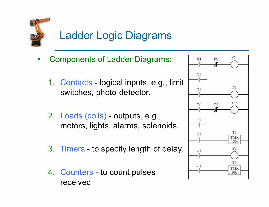
§ Components of Ladder Diagrams:
1. Contacts - logical inputs, e.g., limit switches, photo-detector.
2. Loads (coils) - outputs, e.g., motors, lights, alarms, solenoids.
3. Timers - to specify length of delay.
4. Counters - to count pulses received
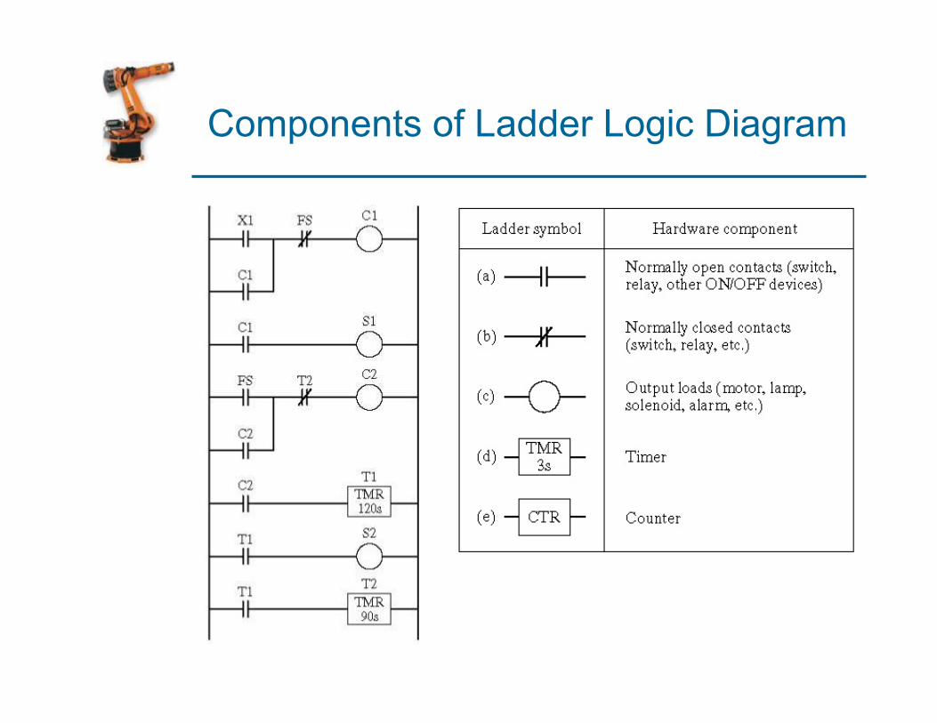
Components of Ladder Logic Diagram

Example 1
§ Construct the ladder logic diagrams for the AND gate.
§ Solution:
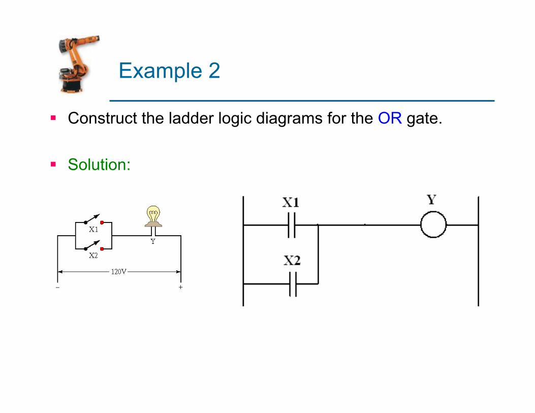
Example 2
§ Construct the ladder logic diagrams for the OR gate.
§ Solution:
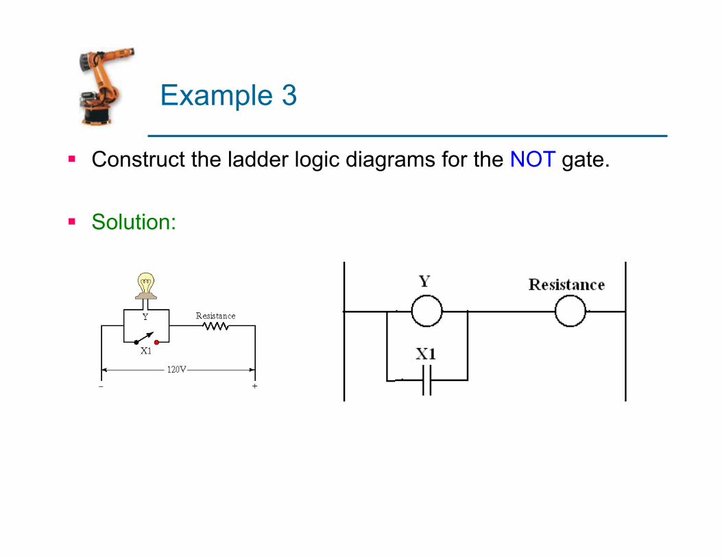
Example 3
§ Construct the ladder logic diagrams for the NOT gate.
§ Solution:
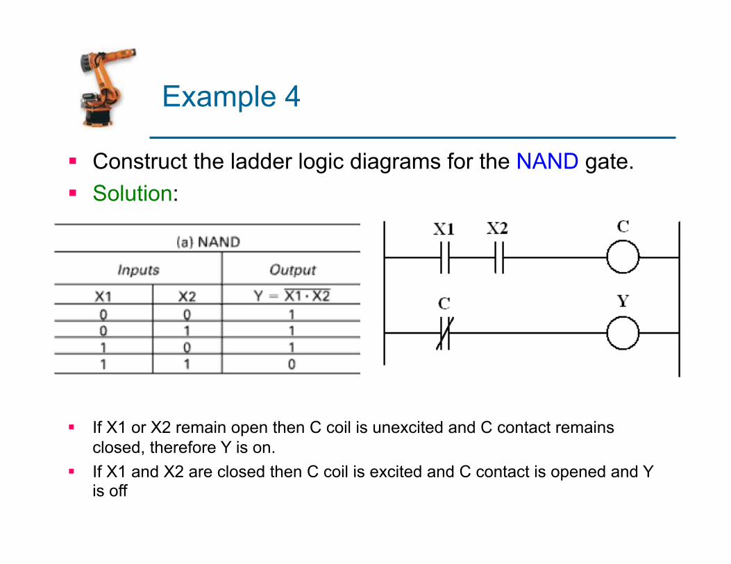
Example 4
§ Construct the ladder logic diagrams for the NAND gate. § Solution:
§ If X1 or X2 remain open then C coil is unexcited and C contact remains closed, therefore Y is on.
§ If X1 and X2 are closed then C coil is excited and C contact is opened and Y is off
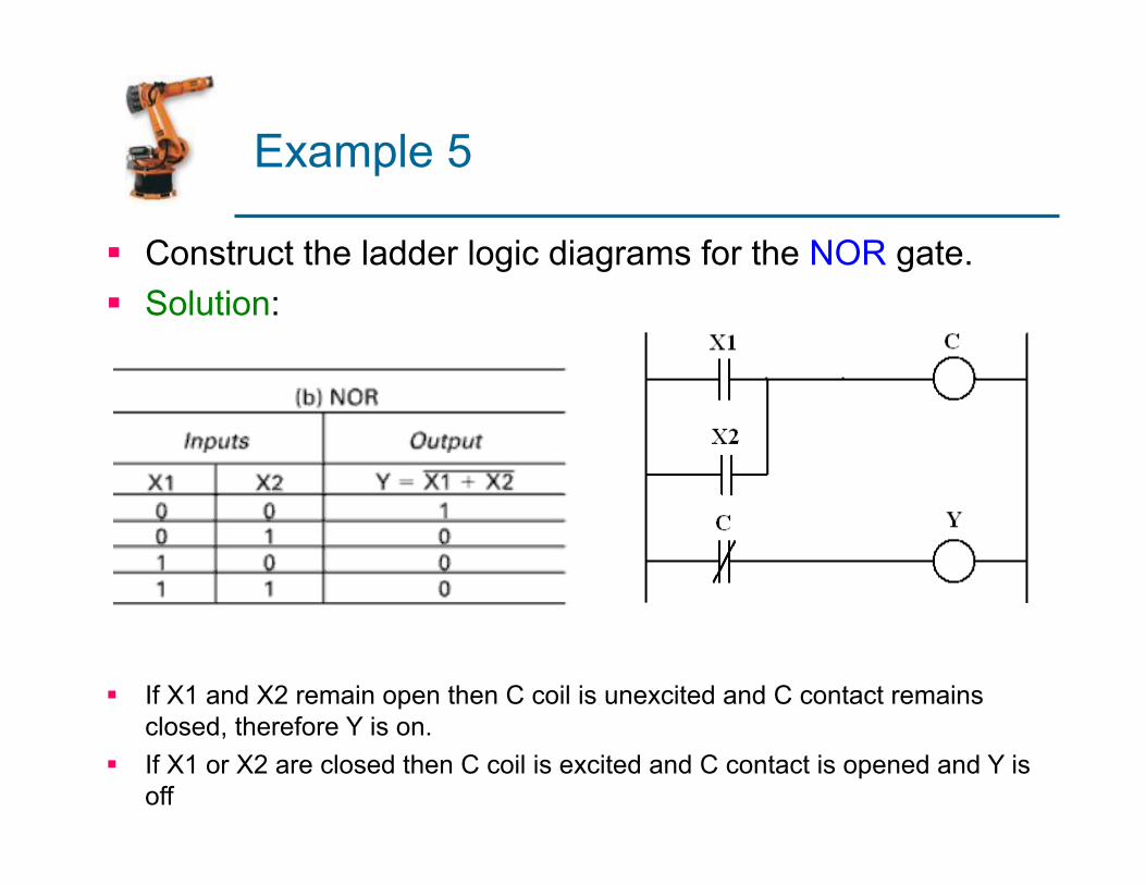
Example 5
§ Construct the ladder logic diagrams for the NOR gate. § Solution:
§ If X1 and X2 remain open then C coil is unexcited and C contact remains closed, therefore Y is on.
§ If X1 or X2 are closed then C coil is excited and C contact is opened and Y is off
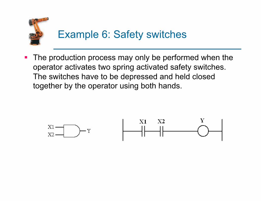
Example 6: Safety switches
§ The production process may only be performed when the operator activates two spring activated safety switches. The switches have to be depressed and held closed together by the operator using both hands.
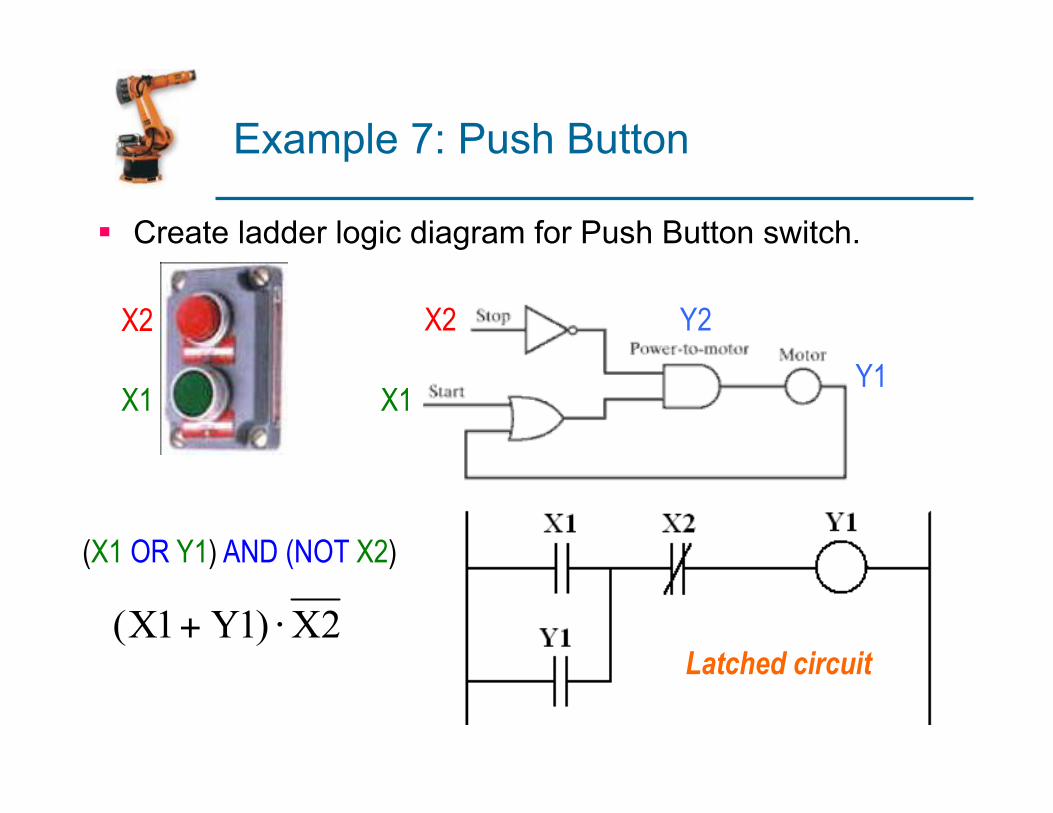
Example 7: Push Button
§ Create ladder logic diagram for Push Button switch.
X1
X2 Y2
Y1
X2
X1
(X1 OR Y1) AND (NOT X2)
Latched circuit
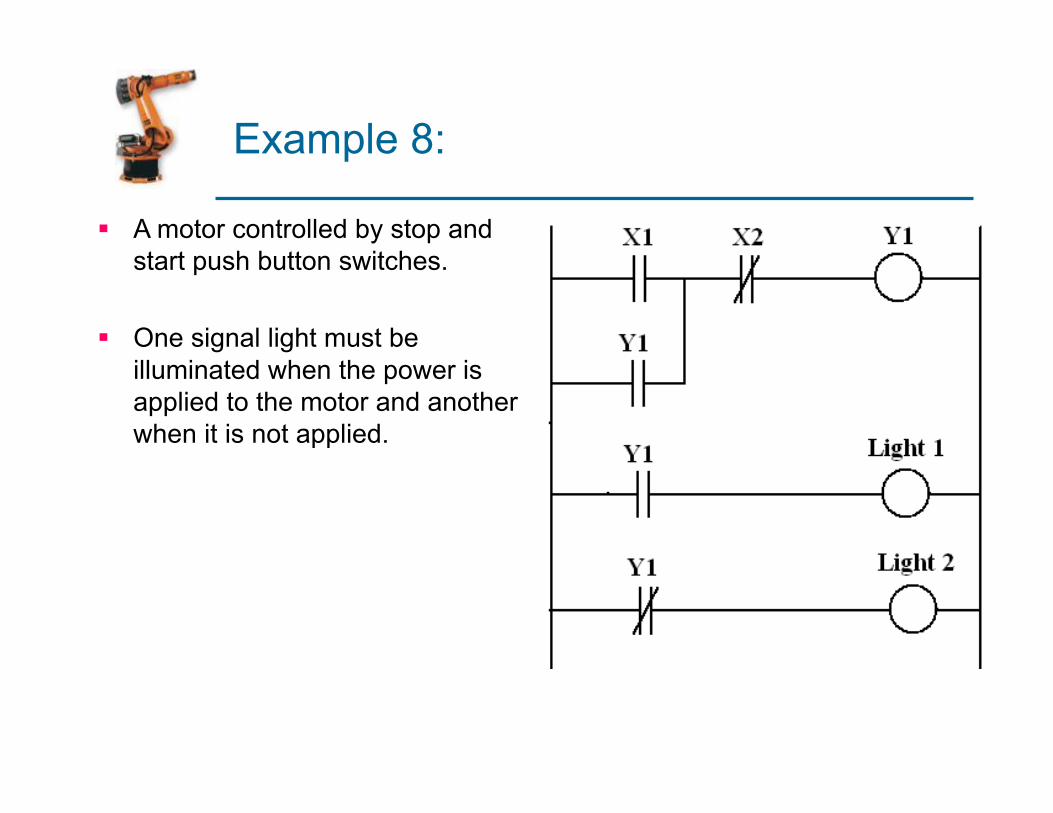
Example 8:
§ A motor controlled by stop and start push button switches.
§ One signal light must be illuminated when the power is applied to the motor and another when it is not applied.
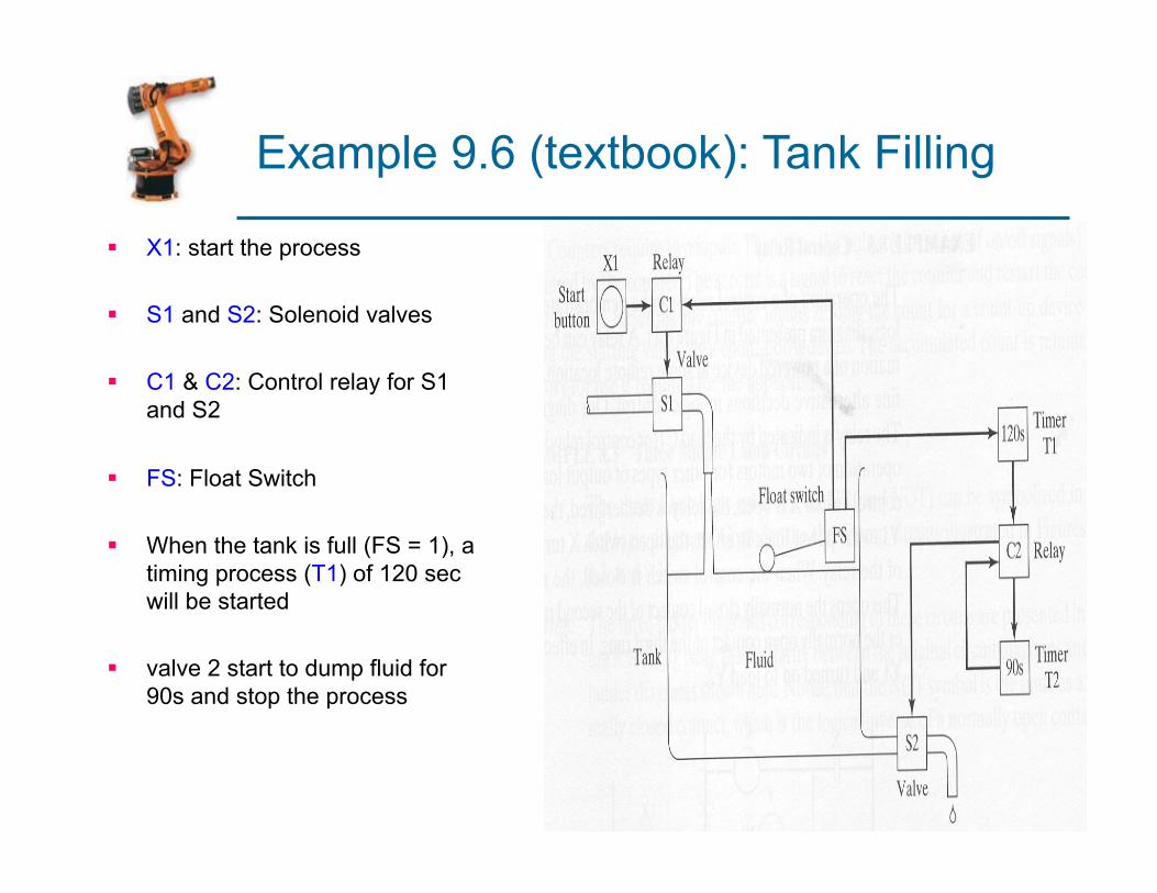
Example 9.6 (textbook): Tank Filling
§ X1: start the process
§ S1 and S2: Solenoid valves
§ C1 & C2: Control relay for S1 and S2
§ FS: Float Switch
§ When the tank is full (FS = 1), a timing process (T1) of 120 sec will be started
§ valve 2 start to dump fluid for 90s and stop the process
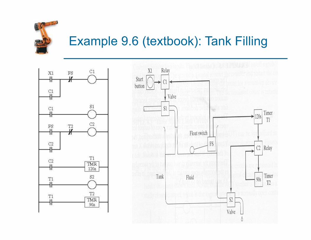
Example 9.6 (textbook): Tank Filling
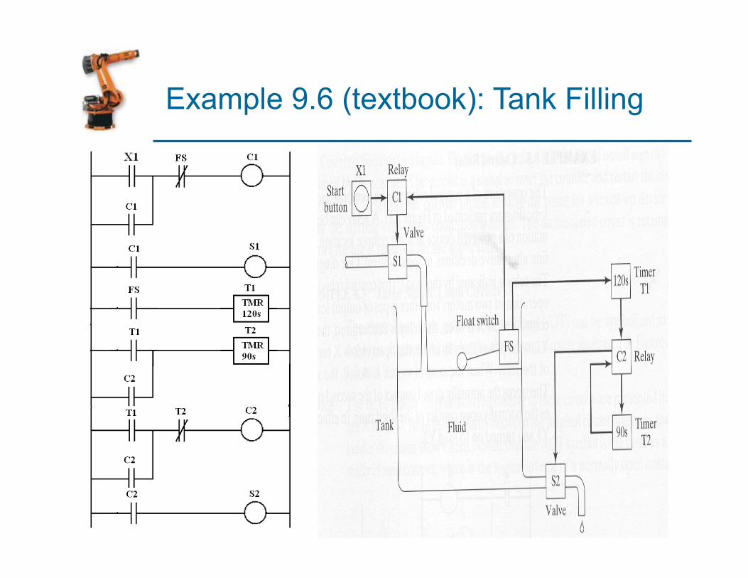
Example 9.6 (textbook): Tank Filling
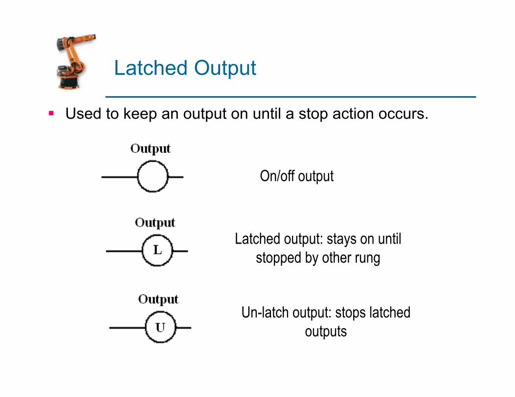
Latched Output
§ Used to keep an output on until a stop action occurs.
On/off output
Latched output: stays on until stopped by other rung
Un-latch output: stops latched outputs
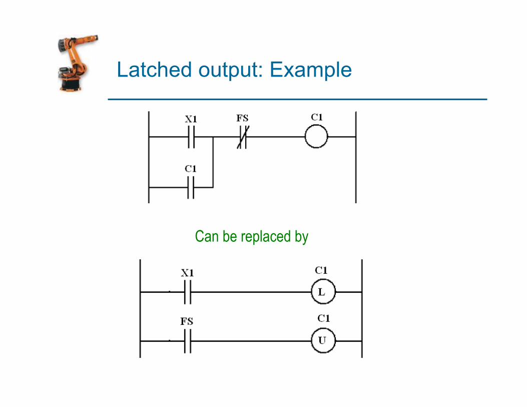
Latched output: Example
Can be replaced by
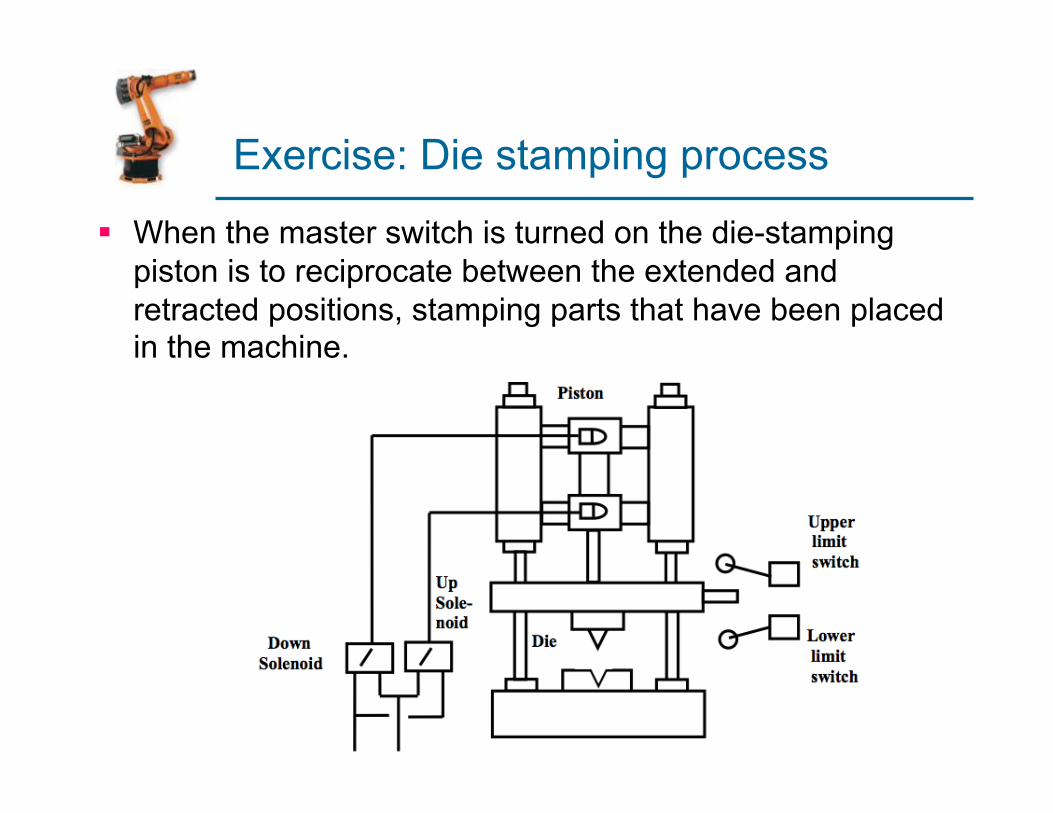
Exercise: Die stamping process
§ When the master switch is turned on the die-stamping piston is to reciprocate between the extended and retracted positions, stamping parts that have been placed in the machine.

Exercise: Die stamping process
Up relay R1
Down relay R2
S2 S1
LS2
LS1
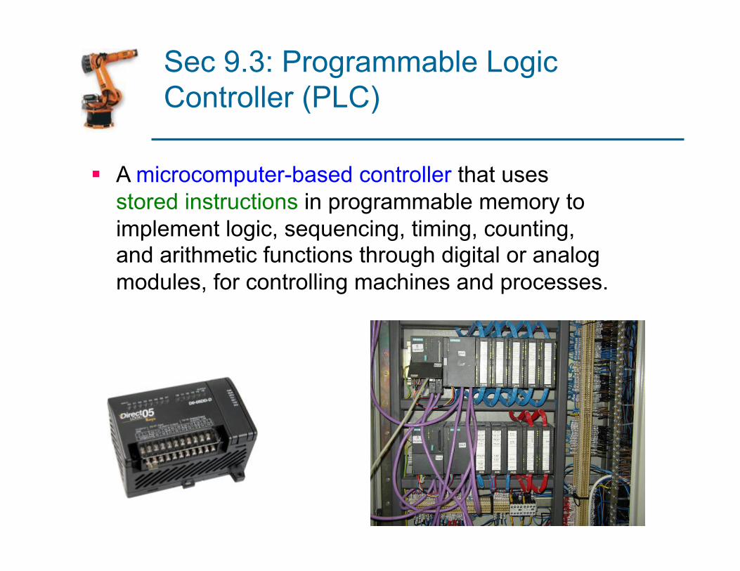
Sec 9.3: Programmable Logic Controller (PLC)
§ A microcomputer-based controller that uses stored instructions in programmable memory to implement logic, sequencing, timing, counting, and arithmetic functions through digital or analog modules, for controlling machines and processes.
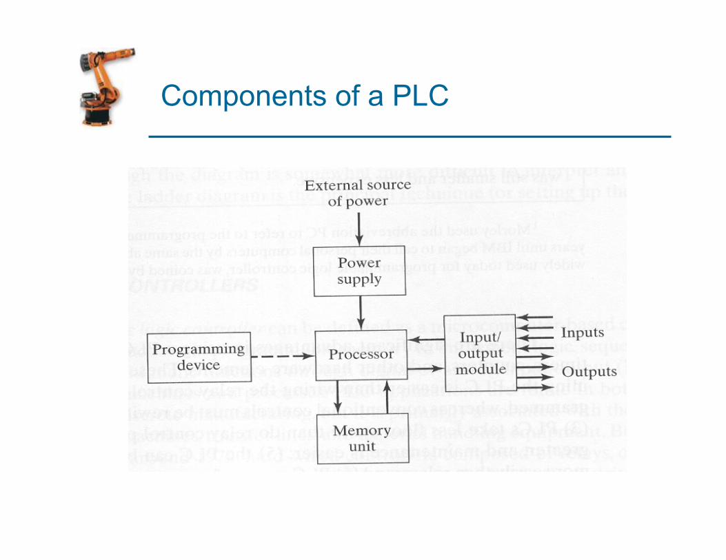
Components of a PLC
Advantages of PLCs Compared to Relay Control Panels
§ Programming a PLC is easier than wiring a relay control panel
§ PLC can be reprogrammed § PLCs take less floor space § Greater reliability, easier maintenance § PLC can be connected to computer systems (CIM) § PLCs can perform a greater variety of control functions
Typical PLC Operating Cycle
1. Input scan – inputs are read by processor and stored in memory
2. Program scan – control program is executed § Input values stored in memory are used in the control
logic calculations to determine values of outputs
3. Output scan – output values are updated to agree with calculated values
§ Time to perform the three steps (scan time) varies between 1 and 25 msec
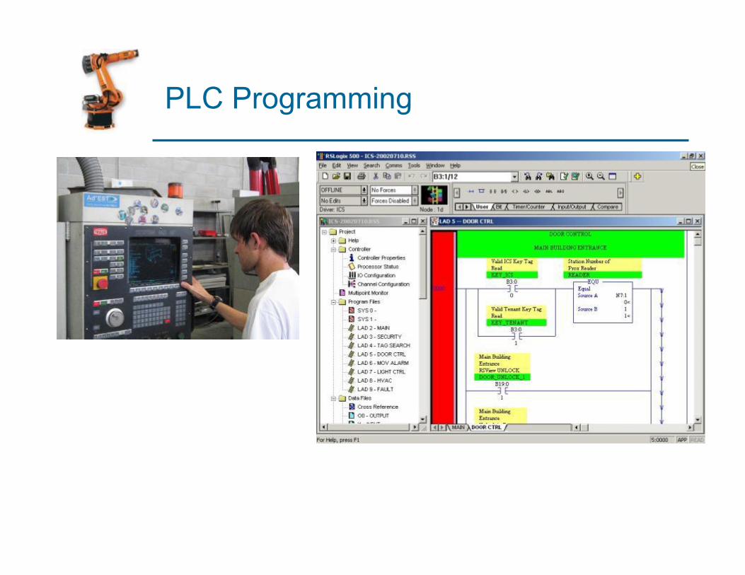
PLC Programming
§ Graphical languages: 1. Ladder logic diagrams – most widely used 2. Function block diagrams – instructions composed
of operation blocks that transform input signals 3. Sequential function charts – series of steps and
transitions from one state to the next (Europe) § Text-based languages:
1. Instruction list - low-level computer language 2. Structured text – high-level computer language
PLC Programming