ece 576, final project: programmable discrete...
TRANSCRIPT

ECE 576, Advanced Microcontroller Design Brian Chu (bc226)
ECE 576, Final Project: Programmable Discrete Graphics Hardware
Introduction
The goal of this final project was to create a programmable graphics processing unit with as
many aspect as possible to be coded in hardware, even with object and edge generation. The
main feature of the organization of this graphics unit is to be able to represent transformation
operations parametrically, creating a graphics co-processor capable of rendering procedural
motion. The graphics unit takes operations in a very-long instruction word format that has a
one-to-one representation to a high-level scripting language, which provides a mean to moving
objects and features in a scene to dynamically during run-time. The original inspiration was
to create a physics simulator on an FPGA that followed Lagrangian constraints, which, if
there were to have been more hardware than software, would have required being able to
manipulate a set of objects in a parametric fashion. The high-level design shares many
similarities multi-cycle pipelines, such as intermediate memories and registers. However,
unlike a regular processor, the co-processor has one pipeline that operates on multiple pieces
of data in parallel, much like a vector processor does in a single-instruction multiple-data
fashion.
There are three components of the circuit: an object generation pipeline to generate edges
of the target shape; a transformation pipeline that performed transformations on the unit
objects1; and a rastering pipeline that generates the points for the VGA controller to display.
The design has made certain tradeoffs due to the constraints imposed by the FPGA we used
to synthesize the circuit. First, the transformation pipeline does not employ a generalized
4x4 matrix multiply because the limited number of multipliers on the FPGA. Instead, the
transformation pipeline is currently designed as a operate-and-accumulate module, with
intermediate data values stored in registers. This most definitely impacts the performance
of the overall system since n transformations take n operations per data set. Alternatively
with more available multipliers, by first generating a reduced matrix transformation, one
data set can be transformed in one cycle. Second, the available memory on the FPGA is
limited to 8.5 megabytes at most, of which about 512 kilobytes are available memory that are
designed to be read from within a single cycle of exerting the desired address. If a different
memory type that provides more storage is made available, several key points of the circuit
would have to be redesigned to adhere to Valid memory lines.
Since this lab was the final project of a one semester course, due to the limited time
available, many other decisions were made to favor rapid development and testing. We
1Unit objects is used in this paper to designate objects that whose sizes are of a single unit of length or volume, whose centeror a specific point to be at the origin of the coordinate system. Further transformations enable the relocation and reshaping ofthe object from its unit specification.
Final Project Report 1 December 2, 2007
ECE 576, Advanced Microcontroller Design Brian Chu (bc226)
present the decisions that, if were made differently, have the most potential to improve the
efficiency of the circuit. One such decisions was to represent the inter-pipeline data using
an exhaustive edges list. This simplified the memory organization at the cost of increase
memory usage, simplified the object generation modules used in the first pipeline2, and
reduced the complexity of the data fetching mechanisms for each pipeline.
High Level Design
The graphics platform was designed to be able to generate shapes and objects by computing
the edges for the object, perform a number of transformations, and to rasterize the scene
into a VGA buffer. The module houses three concurrent pipelines: one to generate an
edge list, one to compute the transformations, and one to rasterize the transformed points.
These three pipelines are implicit consumer-producer constructs, with one waiting for the
completion of the previous before continuing.
The Altera Cyclone II FPGA on the Altera DE2 board was used to synthesize the Verilog
designs. The software used to program the FPGA and organize the DE2 was the Altera
Quartus II. Additionally, a the NIOS II CPU was also available to run software specified in
C to interact with the hardware.
One of the constraints was where to store the edge list, since its the most consumed
resource in an organization of this kind. With the three available memories on board -
SRAM, SDRAM, and M4K blocks3 - M4K blocks were chosen to hold the edge list. This
allowed the memory to be fully simulated in an independent development environment and
did not require waiting a cycle for memory to respond.
Communication between two consumer-producer objects were maintained by having all
the pipelines advance on the same clock, and by having a producer pipeline atomically
incrementing the global count of produced objects. The consumer pipeline maintained its
own counter/iterator as it consumed the data. This way the larger three pipeline dealt with
data stalls implicitly and without a centralized dispatch logic.
From the beginning, the design of the project included as little software as possible in order
to emphasize writing and testing Verilog.4 For the original specification, it was believed that
it would have been possible to completely implement the desired system within the realms
of hardware. Thus, the hardware is especially general, and lends itself to quick and simple
feature extensions. For example, the implied consumer-producer setup allows any additional
pipelines to be quickly created and inserted without having to modify any dispatch logic.
Although this decision has greatly simplified initial development, further development could2The most notable exception to this is generating the edges for a sphere/torus.3Flash may also have been available but the group was unfamiliar with its operation on the DE2 board.4Additionally, a pre-requisite for this course, ECE476, had already heavily emphasized software and C programming in
microcontrollers.
Final Project Report 2 December 2, 2007

ECE 576, Advanced Microcontroller Design Brian Chu (bc226)
demand more memory to store the intermediate data between pipelines, which may exhaust
the memory capacity available on the DE2 board, in which case it would be beneficial
to create a stalling mechanism and multiple VGA buffers in order to compensate for the
decreased resilience of the whole circuit.
There was no known industry standard relevant to this project. There is intellectual
property protection relevant to this project. There is Verilog made public by Terasic for
many of the common designs for the Altera DE2 board. There is Altera’s NIOS II CPU
that, while the current iteration of the circuit does not employ, future extensions will.
Hardware Design
As described in the high level design, there are three pipelines to generate the edges to
objects, to compute transformations on the points, and to rasterize the computed elements.
Since the DE2 hardware also drives the VGA signal through the third rastering pipeline,
which must modifies VGA screen buffer and must be clocked to the VGA control clock, the
other two pipelines are also clocked to the VGA control clock.
The first two pipelines need to store all its data in M4K blocks in order to make them to
the pipeline downstream. Since the last pipeline also serves the VGA controller, the third
pipeline stores its data in SRAM.
Prior considerations to quickly and simply verify the Verilog for any of these pipelines led
to the division between any two producer-consumer pipelines. It is much simpler to test the
first two pipelines, which operate in constant/O(1) complexity, without having deal with the
data stalls imposed by the rastering pipeline, which currently operates with O(n) complexity
and behaves sequentially.
Object Pipeline
As many edge generators for objects can be incorporated into the design. For now, only
a circle and a cube have been implemented.5 Although the edge generators aim to always
generate a valid edge once per cycle, the pipeline can deal with pauses that are inherent to
the algorithm and only save edges when the busy line for each corresponding generator is
high.
The pipeline selects one generator - currently tied to the onboard switches on the DE2 -
initializes the arguments to the generator, and raises the init line for that generator. The
generator will raise its busy line when there is a few valid edge available through its output
lines [(Ax, Ay, Az), (Bx, By, Bz)], and raise done when it is done. done is asserted for
as long as init is high. Deasserting init and waiting one cycle will reset the module. As
5A sphere/torus generator was also begin worked on.
Final Project Report 3 December 2, 2007

ECE 576, Advanced Microcontroller Design Brian Chu (bc226)
long as the generator is designed with this format and communication method, the generator
will work with the driving circuitry in the objects pipeline.
For each edge that is generated and saved, edge count is incremented.
Computation Pipeline
The computation pipeline consumes edges generated by the object pipeline, and monitors
edge count for new edges to operate on. It maintains its own counter, edge iterator,
which it uses to fetch the edge from the edge list and to save the computed edge into its own
memory.
Unfortunately, there were not enough multipliers on the DE2 to have two concurrent 4x4
matrix multiplies for 18-bit wide operands6. Thus, the individual types of transformations
were implemented which would operate on a intermediate register file store the 4x1 vector
of points. Although this used fewer multipliers, the computation time for each edge was
linear compared to the number of transformations instead of being a single 4x4 collapsed
transformation matrix multiply.
The computation pipeline would fetch the operation control word for every cycle, select
the proper hardware, and save the results back to the intermediate register. Each trans-
formation could take up to three 16-bit arguments. Also, in order to support parametrized
transformations, a scaling multiplier would operate on each of the three 16-bit arguments be-
fore reaching the transformation hardware. The three transformations currently supported
are scaling, translation, and rotation on x, y, z axises. Their general types are represented
below:
• Translation:1 0 0 k ·Dx
0 1 0 k ·Dy
0 0 1 k ·Dz
0 0 0 1
x
y
z
1
=
x+ k ·Dx
y + k ·Dy
z + k ·Dz
1
• Scaling:
k · Sx 0 0 0
0 k · Sy 0 0
0 0 k · Sz 0
0 0 0 1
x
y
z
1
=
xkSx
ykSy
zkSz
1
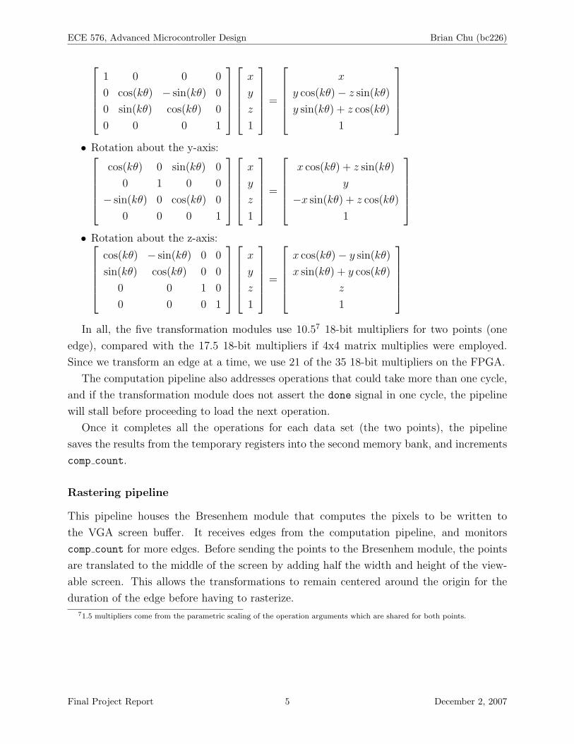
• Rotation about the x-axis:
6There are only 35 18-bit multipliers on the Cyclone II FPGA, and many have been reserved for other purposes, includingfor object generation and for the NIOS II, if and when instantiated.
Final Project Report 4 December 2, 2007
ECE 576, Advanced Microcontroller Design Brian Chu (bc226)
1 0 0 0
0 cos(kθ) − sin(kθ) 0
0 sin(kθ) cos(kθ) 0
0 0 0 1
x
y
z
1
=
x
y cos(kθ)− z sin(kθ)
y sin(kθ) + z cos(kθ)
1
• Rotation about the y-axis:
cos(kθ) 0 sin(kθ) 0
0 1 0 0
− sin(kθ) 0 cos(kθ) 0
0 0 0 1
x
y
z
1
=
x cos(kθ) + z sin(kθ)
y
−x sin(kθ) + z cos(kθ)
1
• Rotation about the z-axis:
cos(kθ) − sin(kθ) 0 0
sin(kθ) cos(kθ) 0 0
0 0 1 0
0 0 0 1
x
y
z
1
=
x cos(kθ)− y sin(kθ)
x sin(kθ) + y cos(kθ)
z
1
In all, the five transformation modules use 10.57 18-bit multipliers for two points (one
edge), compared with the 17.5 18-bit multipliers if 4x4 matrix multiplies were employed.
Since we transform an edge at a time, we use 21 of the 35 18-bit multipliers on the FPGA.
The computation pipeline also addresses operations that could take more than one cycle,
and if the transformation module does not assert the done signal in one cycle, the pipeline
will stall before proceeding to load the next operation.
Once it completes all the operations for each data set (the two points), the pipeline
saves the results from the temporary registers into the second memory bank, and increments
comp count.
Rastering pipeline
This pipeline houses the Bresenhem module that computes the pixels to be written to
the VGA screen buffer. It receives edges from the computation pipeline, and monitors
comp count for more edges. Before sending the points to the Bresenhem module, the points
are translated to the middle of the screen by adding half the width and height of the view-
able screen. This allows the transformations to remain centered around the origin for the
duration of the edge before having to rasterize.
71.5 multipliers come from the parametric scaling of the operation arguments which are shared for both points.
Final Project Report 5 December 2, 2007

ECE 576, Advanced Microcontroller Design Brian Chu (bc226)
Implementation Details
Number representation
The number representation we chose was the 18-bit (or 16-bit, depending on the part of the
meta-pipeline) fixed point. Originally we attempted to implemented a simpler version of
IEEE floating point specification (IEEE754) - specifically without infinity and NaN support
- so that number conversions from software on the NIOS II could be as easy as a cast in C.
However, the idea was scrapped in the interests of time, since a prior lab in the class already
introduced us to the 18-bit fixed point format.
Function tables
Two function tables were pre-calculated. A sine and a cosine table, each with 512 evaluation
points, were generated in C and ported over to 16-bit fixed point notations, and then actuated
in M4K blocks. While a cosine table was explicitly not required, one was generated in order
to fix a bug that presented itself when a sine table was used even though the argument was
offset by π/2.
Graphics operation word format
Currently the graphics operation word is 56 bits long. The significance of the bits are
described below:
• Bits 55 to 53: The opcode. With five different types of operations, we used three bits to
represent the desired operation. 0b000 is rotation about the x-axis, 0b001 is rotation
about the y-axis, 0b010 is rotation about the z-axis, 0b100 is translation, 0b101 is
scaling.
• Bits 52 to 48: An index to a parametrized value. Updating parametrized values was
not implemented, but 5 bits were reserved to index into a structure or table of values
that would be updated upon very frame. Specifying 0b00000 would be always return a
value of 1 (no parametrization).
• Bits 47 to 32, 31 to 16, and 15 to 0: The three 16-bit arguments to the transformations.
For translation and scaling, all three values are used for the x-, y-, and z-transformations.
For rotation, only the first is used as θ, the degree of rotation, represented as units of
2π/512 radians.
Final Project Report 6 December 2, 2007

ECE 576, Advanced Microcontroller Design Brian Chu (bc226)
Testing and Verification
Most of the modules were developed without downloading the code onto the DE2 board.
Thus, the source code has many $display and $finish calls embedded throughout the
circuit.
Additionally, since the number representation is 16-bit fixed-point, several helper C pro-
grams were written generate the sine and cosine tables and to ensure that other portions of
the Verilog were functioning correctly. These programs have been included in the source zip
file.
A sample target scripting language
The graphics operation word format was inspired by a motion description language8. If there
were more time available, a NIOS II CPU would have been implemented in order to parse
the input and write the opwords to the graphics unit. The hardware would handle the rest
and display the result on VGA.
The commands that would be immediately relevant in this circuit are described below:
• square [dx dy dz [sx sy sz]] - Without the optional arguments denoted in square
brackets, a square of unit size would be placed at the origin. (dx, dy, dz) denotes the
center of the square in the global coordinate frame. (sx, sy, sz) denotes the scale of
each dimension of the square, so any rectangular prism can be actuated.
• circle [dx dy dz [sx sy]] - Similar to the square command, circle would gener-
ate a two-dimensional circle at the specified origin and scale, so ellipses can be realized.
• vary knobname v0 v1 f0 f1 - This command will vary any variable with same name
as knobname in linear steps starting from frame number f0 to frame number f1 be-
tween values v0 and v1. With proper support in the parser, the square and circle
commands can be represented using knob values. For example, the hardware already
has preliminary support for parametric values for any graphical transformation, so a
command list such as square 0 k1 0 and vary k1 0 10 0 10 will display a square
whose center moves from (0, 0, 0) to (0, 10, 0) in 10 frames.
Many more scripting commands can be incorporated, including, but not limited to: spec-
ifying coordinate systems whose displacement (dx, dy, dz) is relative to that coordinate
system; specifying a camera angle, which can also be controlled by knobs; and generating
even more shapes, such as a sphere or torus with adjustable minor and major radii.
8The motion description language (MDL) is used in Michael Zamansky’s MCS6 graphics class. In its fully-featured form, itcan describe and animate a scene of objects. Stuyvesant MCS6 home page.
Final Project Report 7 December 2, 2007

ECE 576, Advanced Microcontroller Design Brian Chu (bc226)
Documentation
First unzip the Lab5.zip file, which has had all the intermediate files removed. Launch
Quartus II, compile the circuit, and download onto the DE2 board.
Currently, the switches and buttons are used to control simple operations. SW[17:16]
is used to control which object is generated. Use 0b00 for a circle and 0b10 for a cube.
SW[9:0] is used to indicate the step size for the circle generator, in units of 2π/512. KEY[3]
is used to reset the whole pipeline and the screen buffer.
The eight seven segment displays display the four points that were last entered into the
Bresenhem module.
Potential Improvements
This project allows room for more improvements and features.
• Formally create a graphics operation cache that would be manipulated on the fly from
software running on a NIOS II.
• Create a NIOS II specifically to generate edges for more complicated objects, and to
place them directly into the edge list.
• Improve the computation pipeline’s speed by collapsing all pending transformations
into one matrix, and then finding a way to fit all the necessary multipliers. This may
involve computing only one point in one edge at a time, which requires fewer multipliers
to be synthesized.
• Create an abstract model in order to be able to use Flash, SRAM, and SDRAM. The
state machines in the pipelines may need to be modified to support waiting for results
from memory to return, since M4K blocks respond with one cycle later. For slow
memories, multiple read ports can be wired and a cache can be created, amortizing
most of the delay in the memory accesses.
• After such an abstract memory model is implemented, then the edge list can be trans-
formed into indices into a point list. This would reduce the number of transformations
needed for objects that are highly connected such as spheres.
• Implement a structure to update parametrized values for each frame.
• Compress the bits in the screen buffer. Currently, we use 16 bits per pixel, which, for
a wireframe, is 16 times more than necessary.
Final Project Report 8 December 2, 2007
ECE 576, Advanced Microcontroller Design Brian Chu (bc226)
• If frames are to be implemented, then at least an additional VGA display buffer would
be needed - one to serve current requests from the VGA controller, and another to be
rasterized from the new points coming from the three pipelines.
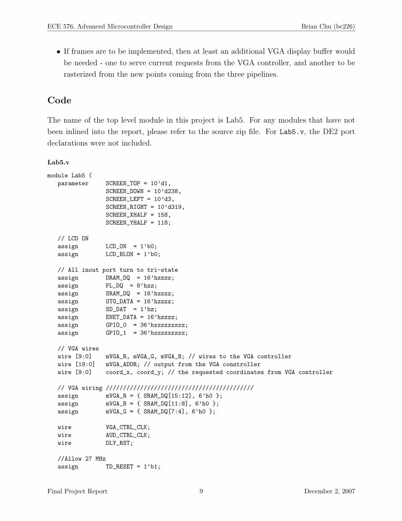
Code
The name of the top level module in this project is Lab5. For any modules that have not
been inlined into the report, please refer to the source zip file. For Lab5.v, the DE2 port
declarations were not included.
Lab5.v
module Lab5 (parameter SCREEN_TOP = 10’d1,
SCREEN_DOWN = 10’d238,SCREEN_LEFT = 10’d3,SCREEN_RIGHT = 10’d319,SCREEN_XHALF = 158,SCREEN_YHALF = 118;
// LCD ONassign LCD_ON = 1’b0;assign LCD_BLON = 1’b0;
// All inout port turn to tri-stateassign DRAM_DQ = 16’hzzzz;assign FL_DQ = 8’hzz;assign SRAM_DQ = 16’hzzzz;assign OTG_DATA = 16’hzzzz;assign SD_DAT = 1’bz;assign ENET_DATA = 16’hzzzz;assign GPIO_0 = 36’hzzzzzzzzz;assign GPIO_1 = 36’hzzzzzzzzz;
// VGA wireswire [9:0] mVGA_R, mVGA_G, mVGA_B; // wires to the VGA controllerwire [19:0] mVGA_ADDR; // output from the VGA conntrollerwire [9:0] coord_x, coord_y; // the requested coordinates from VGA controller
// VGA wiring ///////////////////////////////////////////assign mVGA_R = { SRAM_DQ[15:12], 6’h0 };assign mVGA_B = { SRAM_DQ[11:8], 6’h0 };assign mVGA_G = { SRAM_DQ[7:4], 6’h0 };
wire VGA_CTRL_CLK;wire AUD_CTRL_CLK;wire DLY_RST;
//Allow 27 MHzassign TD_RESET = 1’b1;
Final Project Report 9 December 2, 2007

ECE 576, Advanced Microcontroller Design Brian Chu (bc226)
wire reset_all;assign reset_all = ~KEY[3];
wire pause_all;assign pause_all = ~KEY[2];
VGA_Audio_PLL v0(.areset(~DLY_RST),.inclk0(CLOCK_27),.c0(VGA_CTRL_CLK),.c1(AUD_CTRL_CLK),.c2(VGA_CLK));
Reset_Delay r0( .iCLK(CLOCK_50),.oRESET(DLY_RST));
VGA_Controller c0(.iCursor_RGB_EN(4’b0111),.oAddress(mVGA_ADDR),.oCoord_X(coord_x),.oCoord_Y(coord_y),.iRed(mVGA_R),.iGreen(mVGA_G),.iBlue(mVGA_B),.oVGA_R(VGA_R),.oVGA_G(VGA_G),.oVGA_B(VGA_B),.oVGA_H_SYNC(VGA_HS),.oVGA_V_SYNC(VGA_VS),.oVGA_SYNC(VGA_SYNC),.oVGA_BLANK(VGA_BLANK),.iCLK(VGA_CTRL_CLK),.iRST_N(DLY_RST));
// vga lockreg lock;
// SRAM data goes to NIOS data in linereg we;reg [17:0] addr_reg;reg [15:0] data_reg;assign SRAM_ADDR[17:0] = addr_reg[17:0];assign SRAM_DQ[15:0] = (we) ? data_reg[15:0] : 16’hzzzz;// SRAM CONTROL /////////////////////////////////////////assign SRAM_UB_N = 0; // hi byte select enabledassign SRAM_LB_N = 0; // lo byte select enableassign SRAM_OE_N = 0; // output enable overriden by WEassign SRAM_WE_N = ~we; // write enableassign SRAM_CE_N = 0; // chip enable
assign LEDR[15:12] = object_state[3:0];assign LEDR[11:08] = comp_state[3:0];assign LEDR[07:04] = raster_state[3:0];assign LEDR[03:00] = 4’d0;assign LEDG[3:0] = ~KEY[3:0];
// state counters
Final Project Report 10 December 2, 2007

ECE 576, Advanced Microcontroller Design Brian Chu (bc226)
reg [3:0] object_state;reg [3:0] comp_state;reg [3:0] raster_state;
// edge listreg signed [15:0] edge_Ax[0:255], edge_Ay[0:255], edge_Az[0:255],
edge_Bx[0:255], edge_By[0:255], edge_Bz[0:255];reg [7:0] edge_count;reg [7:0] edge_iterator;// computed edgesreg signed [15:0] comp_Ax[0:255], comp_Ay[0:255], comp_Az[0:255],
comp_Bx[0:255], comp_By[0:255], comp_Bz[0:255];reg [7:0] comp_count;reg [7:0] comp_iterator;
// bresenhem wiresreg bresenhem_init;reg [9:0] bre_Ax, bre_Ay, bre_Bx, bre_By;wire bresenhem_busy, bresenhem_done;wire bresenhem_we;wire [8:0] bresenhem_addr_reg_x, bresenhem_addr_reg_y;wire [1:0] bresenhem_data_reg;
bresenhem bresenhem_instance(.CLK(VGA_CTRL_CLK),.reset(reset_all),.init(bresenhem_init),.lock((~VGA_VS | ~VGA_HS) & ~pause_all),.busy(bresenhem_busy),.done(bresenhem_done),.Ax_in(bre_Ax),.Ay_in(bre_Ay),.Bx_in(bre_Bx),.By_in(bre_By),.we(bresenhem_we),.addr_reg_x(bresenhem_addr_reg_x),.addr_reg_y(bresenhem_addr_reg_y),.data_reg(bresenhem_data_reg));
// circle wiresreg circle_init;wire circle_busy, circle_done;wire [15:0] circle_Ax, circle_Ay, circle_Az, circle_Bx, circle_By, circle_Bz;reg [15:0] circle_stepsize;
circle_gen circle_generator(.CLK(VGA_CTRL_CLK),.reset(reset_all),.init(circle_init), .lock(1’b1),.busy(circle_busy), .done(circle_done),.Ax(circle_Ax), .Ay(circle_Ay), .Az(circle_Az),.Bx(circle_Bx), .By(circle_By), .Bz(circle_Bz),.stepsize(circle_stepsize));
// cube wiresreg cube_init;wire cube_busy, cube_done;
Final Project Report 11 December 2, 2007

ECE 576, Advanced Microcontroller Design Brian Chu (bc226)
wire [15:0] cube_Ax, cube_Ay, cube_Az, cube_Bx, cube_By, cube_Bz;
cube_gen cube_generator(.CLK(VGA_CTRL_CLK),.reset(reset_all),.init(cube_init), .lock(1’b1),.busy(cube_busy), .done(cube_done),.Ax(cube_Ax), .Ay(cube_Ay), .Az(cube_Az),.Bx(cube_Bx), .By(cube_By), .Bz(cube_Bz));
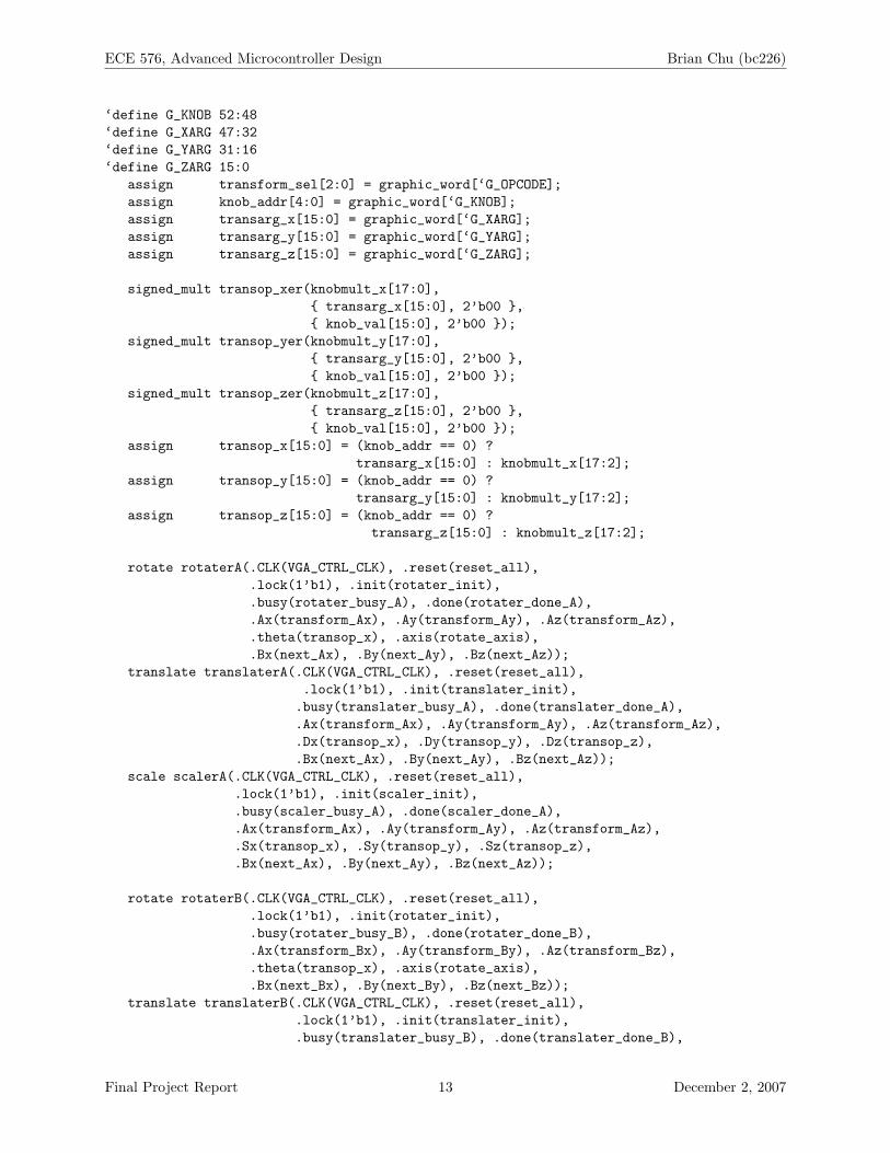
// transformation wiresreg [55:0] graphic_word;reg translater_init, scaler_init, rotater_init;wire [4:0] knob_addr;reg [15:0] knob_val; // obviouswire [15:0] transarg_x, transarg_y, transarg_z; // non-knob-multipliedwire [17:0] knobmult_x, knobmult_y, knobmult_z;// processed op (knob-multiplied or not)wire [15:0] transop_x, transop_y, transop_z;wire [1:0] rotate_axis;// status wires per modulewire translater_busy_A, translater_done_A;wire translater_busy_B, translater_done_B;wire scaler_busy_A, scaler_done_A;wire scaler_busy_B, scaler_done_B;wire rotater_busy_A, rotater_done_A;wire rotater_busy_B, rotater_done_B;// all status wireswire translater_busy, translater_done;wire scaler_busy, scaler_done;wire rotater_busy, rotater_done;// if either are busy, don’t advanceassign translater_busy = translater_busy_A | translater_busy_B;assign scaler_busy = scaler_busy_A | scaler_busy_B;assign rotater_busy = rotater_busy_A | rotater_busy_B;// if both aren’t done, not doneassign translater_done = translater_done_A & translater_done_B;assign scaler_done = scaler_done_A & scaler_done_B;assign rotater_done = rotater_done_A & rotater_done_B;// temporary registersreg [15:0] transform_Ax, transform_Ay, transform_Az;reg [15:0] transform_Bx, transform_By, transform_Bz;wire [15:0] next_Ax, next_Ay, next_Az;wire [15:0] next_Bx, next_By, next_Bz;// transformation and rotation selectionwire [2:0] transform_sel;assign rotate_axis[1:0] = transform_sel[1:0];// transform opsreg [55:0] graphic_ops [0:4];reg [4:0] graphic_ops_count;reg [4:0] graphic_ops_iterator;// 56-bit control word// opcode 3 bits wide// 3x16 transformation arguments// 5 bit knob handler
‘define G_OPCODE 55:53
Final Project Report 12 December 2, 2007
ECE 576, Advanced Microcontroller Design Brian Chu (bc226)
‘define G_KNOB 52:48‘define G_XARG 47:32‘define G_YARG 31:16‘define G_ZARG 15:0
assign transform_sel[2:0] = graphic_word[‘G_OPCODE];assign knob_addr[4:0] = graphic_word[‘G_KNOB];assign transarg_x[15:0] = graphic_word[‘G_XARG];assign transarg_y[15:0] = graphic_word[‘G_YARG];assign transarg_z[15:0] = graphic_word[‘G_ZARG];
signed_mult transop_xer(knobmult_x[17:0],{ transarg_x[15:0], 2’b00 },{ knob_val[15:0], 2’b00 });
signed_mult transop_yer(knobmult_y[17:0],{ transarg_y[15:0], 2’b00 },{ knob_val[15:0], 2’b00 });
signed_mult transop_zer(knobmult_z[17:0],{ transarg_z[15:0], 2’b00 },{ knob_val[15:0], 2’b00 });
assign transop_x[15:0] = (knob_addr == 0) ?transarg_x[15:0] : knobmult_x[17:2];
assign transop_y[15:0] = (knob_addr == 0) ?transarg_y[15:0] : knobmult_y[17:2];
assign transop_z[15:0] = (knob_addr == 0) ?transarg_z[15:0] : knobmult_z[17:2];
rotate rotaterA(.CLK(VGA_CTRL_CLK), .reset(reset_all),.lock(1’b1), .init(rotater_init),.busy(rotater_busy_A), .done(rotater_done_A),.Ax(transform_Ax), .Ay(transform_Ay), .Az(transform_Az),.theta(transop_x), .axis(rotate_axis),.Bx(next_Ax), .By(next_Ay), .Bz(next_Az));
translate translaterA(.CLK(VGA_CTRL_CLK), .reset(reset_all),.lock(1’b1), .init(translater_init),
.busy(translater_busy_A), .done(translater_done_A),
.Ax(transform_Ax), .Ay(transform_Ay), .Az(transform_Az),
.Dx(transop_x), .Dy(transop_y), .Dz(transop_z),
.Bx(next_Ax), .By(next_Ay), .Bz(next_Az));scale scalerA(.CLK(VGA_CTRL_CLK), .reset(reset_all),
.lock(1’b1), .init(scaler_init),
.busy(scaler_busy_A), .done(scaler_done_A),
.Ax(transform_Ax), .Ay(transform_Ay), .Az(transform_Az),
.Sx(transop_x), .Sy(transop_y), .Sz(transop_z),
.Bx(next_Ax), .By(next_Ay), .Bz(next_Az));
rotate rotaterB(.CLK(VGA_CTRL_CLK), .reset(reset_all),.lock(1’b1), .init(rotater_init),.busy(rotater_busy_B), .done(rotater_done_B),.Ax(transform_Bx), .Ay(transform_By), .Az(transform_Bz),.theta(transop_x), .axis(rotate_axis),.Bx(next_Bx), .By(next_By), .Bz(next_Bz));
translate translaterB(.CLK(VGA_CTRL_CLK), .reset(reset_all),.lock(1’b1), .init(translater_init),.busy(translater_busy_B), .done(translater_done_B),
Final Project Report 13 December 2, 2007

ECE 576, Advanced Microcontroller Design Brian Chu (bc226)
.Ax(transform_Bx), .Ay(transform_By), .Az(transform_Bz),
.Dx(transop_x), .Dy(transop_y), .Dz(transop_z),
.Bx(next_Bx), .By(next_By), .Bz(next_Bz));scale scalerB(.CLK(VGA_CTRL_CLK), .reset(reset_all),
.lock(1’b1), .init(scaler_init),
.busy(scaler_busy_B), .done(scaler_done_B),
.Ax(transform_Bx), .Ay(transform_By), .Az(transform_Bz),
.Sx(transop_x), .Sy(transop_y), .Sz(transop_z),
.Bx(next_Bx), .By(next_By), .Bz(next_Bz));
parameter draw_circle = 4’d0,wait_circle = 4’d1,draw_lines = 4’d2,wait_lines = 4’d3,keyok_lines = 4’d8,transform_prep = 4’d4,transform_exec = 4’d5,transform_wait = 4’d6,transform_save = 4’d7;
parameter debug_transform = 1’b0;
// consumer of objects, producer of edge listalways @(posedge VGA_CTRL_CLK) begin
if (reset_all) beginedge_count <= 8’d0;object_state <= draw_circle;
endelse if (object_state == draw_circle) begin
//circle_stepsize <= 16’d100;//circle_stepsize <= 16’d32;//circle_stepsize <= 16’d8;circle_stepsize <= SW[9:0];
if (SW[17:16] == 2’b00) begincircle_init <= 1’b1;cube_init <= 1’b0;
endelse if (SW[17:16] == 2’b10) begin
circle_init <= 1’b0;cube_init <= 1’b1;
end
object_state <= wait_circle;endelse if (object_state == wait_circle) begin
if (circle_busy | cube_busy) beginedge_Ax[edge_count] <= (SW[17:16] == 2’b00) ? circle_Ax : cube_Ax;edge_Ay[edge_count] <= (SW[17:16] == 2’b00) ? circle_Ay : cube_Ay;edge_Az[edge_count] <= (SW[17:16] == 2’b00) ? circle_Az : cube_Az;edge_Bx[edge_count] <= (SW[17:16] == 2’b00) ? circle_Bx : cube_Bx;edge_By[edge_count] <= (SW[17:16] == 2’b00) ? circle_By : cube_By;edge_Bz[edge_count] <= (SW[17:16] == 2’b00) ? circle_Bz : cube_Bz;edge_count <= edge_count + 8’d1;
end // if (circle_busy)
Final Project Report 14 December 2, 2007

ECE 576, Advanced Microcontroller Design Brian Chu (bc226)
else if (circle_done | cube_done) begincircle_init <= 1’b0;
endend // if (object_state == wait_circle)
end // always @ (posedge VGA_CTRL_CLK)
// consumer of edge list, producer of computed edgesalways @(posedge VGA_CTRL_CLK) begin
if (reset_all) beginedge_iterator <= 8’d0;comp_count <= 8’d0;
graphic_ops_iterator <= 0;
// initialize the graphics ops heregraphic_ops_count <= 4;graphic_ops[0] = { 3’b101, 5’d0, 16’d1 << 13, 16’d1 << 13, 16’d1 << 13};//graphic_ops[0] = { 3’b101, 5’d0, 16’d1 << 12, 16’d1 << 12, 16’d1 << 12};graphic_ops[1] = { 3’b100, 5’d0, 16’d20, 16’d20, 16’d20 };// rotate about x-axis 45 degreesgraphic_ops[2] = { 3’b000, 5’d0, 16’h0200, 16’d20, 16’d20 };// rotate about y-axis 45 degreesgraphic_ops[3] = { 3’b001, 5’d0, 16’h0010, 16’d20, 16’d20 };// scale by 0.5//graphic_ops[0] = { 3’b101, 5’d0, 16’d1 << 13, 16’d1 << 13, 16’d1 << 13};// translate by +20//graphic_ops[1] = { 3’b100, 5’d0, 16’d20, 16’d20, 16’d20 };
// translate +20, +20, +20. works perfectly// graphic_word[55:0] = { 3’b100, 5’d0, 16’d20, 16’d20, 16’d20 };// for every unit of scale required, must right shift by 14//graphic_word[55:0] = { 3’b101, 5’d0, 16’d2, 16’d2, 16’d2 };// rotate 180 == 256 steps//graphic_word[55:0] = { 3’b010, 5’d0, 16’d256, 16’d2, 16’d2 };//graphic_word[55:0] = { 3’b010, 5’d0, 16’d128, 16’d0, 16’d0 };
comp_state <= transform_prep;end // if (reset_all)// blocking on edge_count.else if (comp_state == transform_prep) begin
if (edge_iterator < edge_count) beginif (debug_transform) begin
$display("op dump: %b", graphic_ops[0]);$display("op dump: %b", graphic_ops[1]);
end// load transform registerstransform_Ax <= edge_Ax[edge_iterator] >>> 8;transform_Ay <= edge_Ay[edge_iterator] >>> 8;transform_Az <= edge_Az[edge_iterator] >>> 8;transform_Bx <= edge_Bx[edge_iterator] >>> 8;transform_By <= edge_By[edge_iterator] >>> 8;transform_Bz <= edge_Bz[edge_iterator] >>> 8;
// select none
Final Project Report 15 December 2, 2007

ECE 576, Advanced Microcontroller Design Brian Chu (bc226)
rotater_init <= 1’b0;translater_init <= 1’b0;scaler_init <= 1’b0;
// go to transform_execcomp_state <= transform_exec;
// load graphics op wordgraphic_word <= graphic_ops[graphic_ops_iterator];
end // if (comp_state == transform_prep)else begin
//$display("in transform_prep waiting for more edges");end
endelse if (comp_state == transform_exec) begin
if (graphic_ops_iterator < graphic_ops_count) beginif (transform_sel == 3’b000 |
transform_sel == 3’b001 |transform_sel == 3’b010) begin// select rotationrotater_init <= 1’b1;translater_init <= 1’b0;scaler_init <= 1’b0;
endelse if (transform_sel == 3’b100) begin
// select translationrotater_init <= 1’b0;translater_init <= 1’b1;scaler_init <= 1’b0;
endelse if (transform_sel == 3’b101) begin
// select scalingrotater_init <= 1’b0;translater_init <= 1’b0;scaler_init <= 1’b1;
endelse begin
$display("TRANSFORMATION DISPATCH: op %d of %d.",graphic_ops_iterator, graphic_ops_count, transop_x);
$finish;end
// wait for transformation to be finished//$display("going to transform_wait");comp_state <= transform_wait;
// increment to the next operationgraphic_ops_iterator <= graphic_ops_iterator + 1;
end // if (graphic_ops_iterator < graphic_ops_count)else begin
$display("transform waiting on exec for more points");$finish;
endend // if (comp_state == transform_exec)
Final Project Report 16 December 2, 2007
ECE 576, Advanced Microcontroller Design Brian Chu (bc226)
else if (comp_state == transform_wait) beginif (rotater_done | translater_done | scaler_done) begin
// save the intermediate valuestransform_Ax <= next_Ax;transform_Ay <= next_Ay;transform_Az <= next_Az;transform_Bx <= next_Bx;transform_By <= next_By;transform_Bz <= next_Bz;
// deselect all the transformation unitsrotater_init <= 1’b0;translater_init <= 1’b0;scaler_init <= 1’b0;
if (graphic_ops_iterator < graphic_ops_count) begin// load graphics op wordgraphic_word <= graphic_ops[graphic_ops_iterator];
// go back to transform_execcomp_state <= transform_exec;
endelse begin
// done statecomp_state <= transform_save;
endend // if (rotater_done | translater_done | scaler_done)
end // if (comp_state == transform_wait)else if (comp_state == transform_save) begin
// writeback// save point into computed rfcomp_Ax[edge_iterator] <= next_Ax;comp_Ay[edge_iterator] <= next_Ay;comp_Az[edge_iterator] <= next_Az;comp_Bx[edge_iterator] <= next_Bx;comp_By[edge_iterator] <= next_By;comp_Bz[edge_iterator] <= next_Bz;comp_count <= comp_count + 8’d1;
// increment edge iteratoredge_iterator <= edge_iterator + 8’d1;
// reset graphics op iteratorgraphic_ops_iterator <= 8’d0;
// go to transform_prep to wait for more edges//comp_state <= transform_prep;comp_state <= transform_prep;
end // if (comp_state == transform_save)end // always @ (posedge VGA_CTRL_CLK)
always @(posedge VGA_CTRL_CLK) beginif (reset_all) begin
// wipe all screen
Final Project Report 17 December 2, 2007

ECE 576, Advanced Microcontroller Design Brian Chu (bc226)
lock <= 1’b1;addr_reg <= { coord_x[9:1], coord_y[9:1] };
if ({1’b0, coord_x[9:1]} <= SCREEN_LEFT |{1’b0, coord_x[9:1]} >= SCREEN_RIGHT |{1’b0, coord_y[9:1]} <= SCREEN_TOP |{1’b0, coord_y[9:1]} >= SCREEN_DOWN) begindata_reg <= 16’hffff;
end else begindata_reg <= 16’h0000;
end
// active-hi savewe <= 1’b1;
// bresenhem varscomp_iterator <= 8’d0;raster_state <= draw_lines;bresenhem_init <= 1’b0;
endelse if ((~VGA_VS | ~VGA_HS) & ~pause_all & ~circle_busy) begin
lock <= 1’b1;
// set the output to the data regaddr_reg <= { bresenhem_addr_reg_x[8:0],
bresenhem_addr_reg_y[8:0] };data_reg <= (bresenhem_data_reg == 2’b01) ? 16’hffff : 16’h0000;we <= bresenhem_we;
if (raster_state == draw_lines) beginif (comp_iterator < comp_count) begin
bre_Ax <= comp_Ax[comp_iterator] + SCREEN_XHALF;bre_Ay <= comp_Ay[comp_iterator] + SCREEN_YHALF;bre_Bx <= comp_Bx[comp_iterator] + SCREEN_XHALF;bre_By <= comp_By[comp_iterator] + SCREEN_YHALF;bresenhem_init <= 1’b1;
comp_iterator <= comp_iterator + 8’d1;
raster_state <= wait_lines;end // if (comp_iterator < comp_count)
end // if (raster_state <= draw_lines)else if (raster_state == wait_lines) begin
if (bresenhem_busy) beginbresenhem_init <= 1’b0;
end//else if (bresenhem_done & (1’b1 & ~KEY[0])) beginelse if (bresenhem_done) begin
bresenhem_init <= 1’b0;raster_state <= draw_lines;
endend // if (raster_state == wait_lines)else if (raster_state == keyok_lines) begin
if (KEY[0]) begin
Final Project Report 18 December 2, 2007
ECE 576, Advanced Microcontroller Design Brian Chu (bc226)
bresenhem_init <= 1’b0;raster_state <= draw_lines;
endend
end // if ((~VGA_VS | ~VGA_HS) & ~pause_all & ~circle_busy)else begin
// drawing to the screenlock <= 1’b0;addr_reg <= { coord_x[9:1], coord_y[9:1] };we <= 1’b0;
endend
// show the addressing being asserted using HEX[7:4]HexDigit Digit0(HEX0, bre_By[3:0]);HexDigit Digit1(HEX1, bre_By[7:4]);HexDigit Digit2(HEX2, bre_Bx[3:0]);HexDigit Digit3(HEX3, bre_Bx[7:4]);HexDigit Digit4(HEX4, bre_Ay[3:0]);HexDigit Digit5(HEX5, bre_Ay[7:4]);HexDigit Digit6(HEX6, bre_Ax[3:0]);HexDigit Digit7(HEX7, bre_Ax[7:4]);// show the contents of that address using HEX[3:0]
endmodule
bresenhem.v
module bresenhem (CLK, reset, init, Ax_in, Ay_in, Bx_in, By_in, lock, busy, done,we, addr_reg_x, addr_reg_y, data_reg);
input CLK;wire CLK;// active-high resetinput reset;wire reset;// external signal to start. ax, ay, bx, by are setinput init;wire init;input signed [9:0] Ax_in, Ay_in, Bx_in, By_in;wire signed [9:0] Ax_in, Ay_in, Bx_in, By_in;// did we lose the lock?input lock;wire lock;// SRAM (or data-store) controloutput we;output [8:0] addr_reg_x, addr_reg_y;output [1:0] data_reg;
reg we; // write enablereg [8:0] addr_reg_x, addr_reg_y;reg [1:0] data_reg;
//reg [17:0] addr_reg;//reg [15:0] data_reg;
Final Project Report 19 December 2, 2007
ECE 576, Advanced Microcontroller Design Brian Chu (bc226)
reg signed [9:0] Ax, Ay, Bx, By;// signal raised to show that the algo. isn’t done// only high if init is high.// is never high when done is high.output busy;reg busy = 1’b0;// signal raised to show that the ax,ay,bx,by line is drawn.// only high for as long as init is not going posedge.output done;reg done = 1’b0;
reg signed [9:0] Ax_last, Ay_last, Bx_last, By_last;reg signed [9:0] dX, dY, Xincr, Yincr;reg signed [9:0] dPr, dPru, P, loop_end;
wire signed [9:0] Ax_incr, Ay_incr;assign Ax_incr = Ax + Xincr;assign Ay_incr = Ay + Yincr;
reg [3:0] state; // state machine variable for current state//reg lock; // the hardware lock
parameter init_line = 4’d0,lineDX = 4’d1,lineDY = 4’d2,done_line = 4’d3,SCREEN_TOP = 10’d1,SCREEN_DOWN = 10’d238,SCREEN_LEFT = 10’d3,SCREEN_RIGHT = 10’d319,debug_drawing = 1’b1,debug_bresenhem = 1’b1;
always @(posedge CLK) beginif (reset) begin
// last lines?Ax_last <= 10’d0;Ay_last <= 10’d0;Bx_last <= 10’d0;By_last <= 10’d0;
busy <= 1’b0;done <= 1’b0;state <= done_line;we <= 1’b0;
end else if (lock) begincase (state)done_line: begin
// progress only if there is new inputif (init == 1’b1) begin
// this may hang if the requester asks the module// to draw the same points twice!// requester must de-asserted init line for at least
Final Project Report 20 December 2, 2007

ECE 576, Advanced Microcontroller Design Brian Chu (bc226)
// one cycle in order to resetif (Ax_in != Ax_last & Ay_in != Ay_last &
Bx_in != Bx_last & By_in != By_last) begin// a new and different line was just requested thru ax,ay,bx,by
// saving to compareAx_last <= Ax_in;Ay_last <= Ay_in;Bx_last <= Bx_in;By_last <= By_in;// saving as state variablesAx <= Ax_in;Ay <= Ay_in;Bx <= Bx_in;By <= By_in;
// setting some differential variables// dX gets abs (Bx - Ax)// Xincr gets (Ax < Bx) or (Bx > Ax)if (Bx_in > Ax_in) begin
dX <= Bx_in - Ax_in;Xincr <= 10’d1;
end else begindX <= Ax_in - Bx_in;Xincr <= -10’d1;
end// dY gets abs (By - Ay)// Yincr gets (Ay < By) or (By > Ay)if (By_in > Ay_in) begin
dY <= By_in - Ay_in;Yincr <= 10’d1;
end else begindY <= Ay_in - By_in;Yincr <= -10’d1;
end
// start drawing this linestate <= init_line;
// not done drawing line. busy.busy <= 1’b1;done <= 1’b0;
end else begin// done drawing the line. finished.busy <= 1’b0;done <= 1’b1;
endend else begin
// communicate to software that we are reset and ready.
// here: nothingbusy <= 1’b0;done <= 1’b0;
Final Project Report 21 December 2, 2007

ECE 576, Advanced Microcontroller Design Brian Chu (bc226)
Ax_last <= 10’d0;Ay_last <= 10’d0;Bx_last <= 10’d0;By_last <= 10’d0;
endend // case: done_lineinit_line: begin
if (dX >= dY) begindPr <= (dY << 10’b1);dPru <= (dY << 10’b1) - (dX << 10’b1);P <= (dY << 10’b1) - dX;loop_end <= dX;
state <= lineDX;end else begin
dPr <= (dX << 10’b1);dPru <= (dX << 10’b1) - (dY << 10’b1);P <= (dX << 10’b1) - dY;loop_end <= dY;
state <= lineDY;end // else: !if(dX >= dY)
// draw the initial point?if (Ax_incr >= SCREEN_LEFT & Ax_incr < SCREEN_RIGHT &
Ay_incr >= SCREEN_TOP & Ay_incr < SCREEN_DOWN) begin// plot the thing//lock <= 1’b1;addr_reg_x <= Ax[8:0];addr_reg_y <= Ay[8:0];//data_reg <= 16’hffff;data_reg <= 2’b01; // white dotwe <= 1’b1;if (debug_drawing) begin
$display("Drawing (%d, %d).", Ax[8:0], Ay[8:0]);end
end else beginwe <= 1’b0;
end // else: !if(Ax >= SCREEN_LEFT & Ax < SCREEN_RIGHT &...
end // case: init_linelineDX: begin
// for the case when dX >= dYif (loop_end > 0) begin
if (P > 0) beginAx <= Ax_incr;Ay <= Ay_incr;P <= P + dPru;
end else beginAx <= Ax_incr;P <= P + dPr;
end // else: !if(P > 0)
// draw?
Final Project Report 22 December 2, 2007
ECE 576, Advanced Microcontroller Design Brian Chu (bc226)
if (Ax_incr >= SCREEN_LEFT & Ax_incr < SCREEN_RIGHT &Ay_incr >= SCREEN_TOP & Ay_incr < SCREEN_DOWN) begin// plot the thing//lock <= 1’b1;//addr_reg <= { Ax_incr[8:0], (P > 0) ? Ay_incr[8:0] : Ay[8:0] };addr_reg_x <= Ax_incr[8:0];addr_reg_y <= (P > 0) ? Ay_incr[8:0] : Ay[8:0];//data_reg <= 16’hffff;data_reg <= 2’b01;we <= 1’b1;
end else beginwe <= 1’b0;
end // else: !if(Ax >= SCREEN_LEFT & Ax < SCREEN_RIGHT &...
loop_end <= loop_end - 1;end // if (loop_end > 0)else begin
state <= done_line;busy <= 1’b0;done <= 1’b1;
end // else: !if(loop_end > 0)end // case: lineDX
lineDY: begin// for the case when dX < dYif (loop_end > 0) begin
if (P > 0) beginif (debug_bresenhem) begin
$display("lineDY_a: Ax = %d, Xincr = %d, Ax + Xincr = %d",Ax, Xincr, Ax_incr);
endAx <= Ax_incr;Ay <= Ay_incr;P <= P + dPru;
end else beginif (debug_bresenhem) begin
$display("lineDY_b: Ax = %d, Xincr = %d, Ax + Xincr = %d",Ax, Xincr, Ax_incr);
endAy <= Ay_incr;P <= P + dPr;
end
// draw?if (Ax_incr >= SCREEN_LEFT & Ax_incr < SCREEN_RIGHT &
Ay_incr >= SCREEN_TOP & Ay_incr < SCREEN_DOWN) begin// plot the thing//lock <= 1’b1;//addr_reg <= { (P > 0) ? Ax_incr[8:0] : Ax[8:0], Ay_incr[8:0] };addr_reg_x <= (P > 0) ? Ax_incr[8:0] : Ax[8:0];addr_reg_y <= Ay_incr[8:0];//data_reg <= 16’hffff;data_reg <= 2’b01; // white dotwe <= 1’b1;
Final Project Report 23 December 2, 2007
ECE 576, Advanced Microcontroller Design Brian Chu (bc226)
end else beginwe <= 1’b0;
end // else: !if(Ax >= SCREEN_LEFT & Ax < SCREEN_RIGHT &...
loop_end <= loop_end - 1;end else begin // if (loop_end > 0)
state <= done_line;busy <= 1’b0;done <= 1’b1;
end // else: !if(loop_end > 0)end // case: lineDY
endcase // case (state)end
end // always @ (posedge CLK)endmodule
circle.v
module circle_gen(CLK, reset, lock, init, busy, done,Ax, Ay, Az, Bx, By, Bz, stepsize);
input CLK, reset, lock, init;wire CLK, reset, lock, init;output busy, done;reg busy, done;output [15:0] Ax, Ay, Az, Bx, By, Bz;wire [15:0] Ax, Ay, Az, Bx, By, Bz;
reg [15:0] prev_x, prev_y, prev_z;reg [15:0] next_x, next_y, next_z;reg [15:0] first_x, first_y, first_z;
assign Ax[15:0] = prev_x;assign Ay[15:0] = prev_y;assign Az[15:0] = prev_z;assign Bx[15:0] = next_x;assign By[15:0] = next_y;assign Bz[15:0] = next_z;
input [15:0] stepsize;wire [15:0] stepsize;
reg [3:0] state;reg [15:0] d_step;reg [15:0] cur_step;
parameter done_looping = 4’d0,looping = 4’d1,wait_for_init_low = 4’d2,debug_circle = 1’b0;
wire [8:0] sine_addr;assign sine_addr[8:0] = cur_step[8:0];wire [15:0] sine_out;wire [8:0] cos_addr;
Final Project Report 24 December 2, 2007
ECE 576, Advanced Microcontroller Design Brian Chu (bc226)
assign cos_addr[8:0] = cur_step[8:0] + 9’d128;wire [15:0] cos_out;sineTable9x16bit sineTable(CLK, sine_addr, sine_out);sineTable9x16bit cosTable(CLK, cos_addr, cos_out);
always @(posedge CLK) beginif (reset) begin
cur_step <= 16’d0;
prev_x <= 16’d0;prev_y <= 16’d0;prev_z <= 16’d0;next_x <= 16’d0;next_y <= 16’d0;next_z <= 16’d0;
busy <= 1’b0;done <= 1’b0;
state <= done_looping;if (debug_circle) $display("circle_gen: being reset");
endelse if (lock) begin
case (state)done_looping: begin
if (init == 1’b1) begin// start querying the sine table nowcur_step <= stepsize;
// delta step. 1, 2, 3, ...d_step <= stepsize;
// not busy yet (no valid results out)busy <= 1’b0;// not done yetdone <= 1’b0;
state <= looping;end // if (init == 1’b1)else begin
busy <= 1’b0;done <= 1’b0;
endendlooping: begin
if (cur_step > 512) begin// not done yet.busy <= 1’b1;done <= 1’b0;
// advance prev_[xyz]prev_x[15:0] <= next_x[15:0];prev_y[15:0] <= next_y[15:0];prev_z[15:0] <= next_z[15:0];
Final Project Report 25 December 2, 2007

ECE 576, Advanced Microcontroller Design Brian Chu (bc226)
// set next_[xyz] to 0next_x[15:0] <= first_x[15:0];next_y <= 16’d0;next_z <= 16’d0;
state <= wait_for_init_low;endelse begin
// initial caseprev_x[15:0] <= next_x[15:0];prev_y[15:0] <= next_y[15:0];prev_z[15:0] <= next_z[15:0];
next_x[15:0] <= cos_out[15:0];next_y[15:0] <= sine_out[15:0];next_z[15:0] <= 16’d0;
// turn busy on after the first line. don’t draw centerif (cur_step != stepsize) beginbusy <= 1’b1;
endelse if (cur_step == stepsize) begin
// save the first point so we can complete circle in the endfirst_x[15:0] <= cos_out[15:0];first_y[15:0] <= sine_out[15:0];first_z[15:0] <= 16’d0;
end// not donedone <= 1’b0;// advancecur_step <= cur_step + d_step;
end // else: !if(cur_step > 512)end // case: loopingwait_for_init_low: begin
// now we’re donebusy <= 1’b0;done <= 1’b1;
if (~init) beginstate <= done_looping;
endend
endcase // case (state)end
end // always @ (posedge CLK)
endmodule // circle_gen
cube.v
module cube_gen(CLK, reset, lock, init, busy, done,Ax, Ay, Az, Bx, By, Bz);
input CLK, reset, lock, init;wire CLK, reset, lock, init;
Final Project Report 26 December 2, 2007

ECE 576, Advanced Microcontroller Design Brian Chu (bc226)
output busy, done;reg busy, done;output [15:0] Ax, Ay, Az, Bx, By, Bz;reg [15:0] Ax, Ay, Az, Bx, By, Bz;
reg [3:0] state;reg [15:0] d_step;reg [15:0] cur_step;
parameter done_looping = 4’d0,looping = 4’d1,wait_for_init_low = 4’d2;
reg [4:0] counter;
always @(posedge CLK) beginif (reset) begin
cur_step <= 16’d0;
Ax <= 16’d0;Ay <= 16’d0;Az <= 16’d0;Bx <= 16’d0;By <= 16’d0;Bz <= 16’d0;
busy <= 1’b0;done <= 1’b0;
state <= done_looping;$display("cube_gen being reset");
endelse if (lock) begin
case (state)done_looping: begin
if (init == 1’b1) begin// not busy yet (no valid results out)busy <= 1’b0;// not done yetdone <= 1’b0;
counter <= 3’b0;
state <= looping;$display("cube_gen: done_looping with init high");
end // if (init == 1’b1)else begin
$display("cube_gen: done_looping with init low");busy <= 1’b0;done <= 1’b0;
endendlooping: begin
// not done yet.
Final Project Report 27 December 2, 2007

ECE 576, Advanced Microcontroller Design Brian Chu (bc226)
busy <= 1’b1;done <= 1’b0;if (counter == 0) begin
Ax <= 16’h4000;Ay <= 16’h4000;Az <= 16’h4000;Bx <= 16’hc000;By <= 16’h4000;Bz <= 16’h4000;
endelse if (counter == 1) begin
Ax <= 16’h4000;Ay <= 16’h4000;Az <= 16’h4000;Bx <= 16’h4000;By <= 16’hc000;Bz <= 16’h4000;
endelse if (counter == 2) begin
Ax <= 16’h4000;Ay <= 16’h4000;Az <= 16’h4000;Bx <= 16’h4000;By <= 16’h4000;Bz <= 16’hc000;
endelse if (counter == 3) begin
Ax <= 16’hc000;Ay <= 16’h4000;Az <= 16’hc000;Bx <= 16’h4000;By <= 16’h4000;Bz <= 16’hc000;
endelse if (counter == 4) begin
Ax <= 16’h4000;Ay <= 16’hc000;Az <= 16’hc000;Bx <= 16’h4000;By <= 16’h4000;Bz <= 16’hc000;
endelse if (counter == 5) begin
Ax <= 16’hc000;Ay <= 16’h4000;Az <= 16’h4000;Bx <= 16’hc000;By <= 16’h4000;Bz <= 16’hc000;
endelse if (counter == 6) begin
Ax <= 16’h4000;Ay <= 16’hc000;Az <= 16’h4000;
Final Project Report 28 December 2, 2007

ECE 576, Advanced Microcontroller Design Brian Chu (bc226)
Bx <= 16’h4000;By <= 16’hc000;Bz <= 16’hc000;
endelse if (counter == 7) begin
Ax <= 16’h4000;Ay <= 16’hc000;Az <= 16’h4000;Bx <= 16’hc000;By <= 16’hc000;Bz <= 16’h4000;
endelse if (counter == 8) begin
Ax <= 16’hc000;Ay <= 16’hc000;Az <= 16’h4000;Bx <= 16’hc000;By <= 16’hc000;Bz <= 16’h4000;
endelse if (counter == 9) begin
Ax <= 16’hc000;Ay <= 16’hc000;Az <= 16’hc000;Bx <= 16’hc000;By <= 16’hc000;Bz <= 16’h4000;
endelse if (counter == 10) begin
Ax <= 16’hc000;Ay <= 16’hc000;Az <= 16’hc000;Bx <= 16’hc000;By <= 16’h4000;Bz <= 16’hc000;
endelse if (counter == 11) begin
Ax <= 16’hc000;Ay <= 16’hc000;Az <= 16’hc000;Bx <= 16’h4000;By <= 16’hc000;Bz <= 16’hc000;state <= wait_for_init_low;
end
counter <= counter + 1;end // case: loopingwait_for_init_low: begin
// now we’re donebusy <= 1’b0;done <= 1’b1;
if (~init) begin
Final Project Report 29 December 2, 2007

ECE 576, Advanced Microcontroller Design Brian Chu (bc226)
state <= done_looping;end
endendcase // case (state)
endend // always @ (posedge CLK)
endmodule // cube_gen
transform.v
module translate(CLK, reset, lock, init, busy, done,Ax, Ay, Az, Dx, Dy, Dz, Bx, By, Bz);
input CLK, reset, lock, init;wire CLK, reset, lock, init;output busy, done;reg busy, done;
input [15:0] Ax, Ay, Az, Dx, Dy, Dz;wire [15:0] Ax, Ay, Az, Dx, Dy, Dz;
output [15:0] Bx, By, Bz;reg [15:0] Bx, By, Bz;
initial begin// we always have single cycle responsebusy <= 1’b0;
end
always @(posedge CLK) beginif (init) begin
done <= 1’b1;
Bx <= Ax + Dx;By <= Ay + Dy;Bz <= Az + Dz;
endelse begin
done <= 1’b0;Bx <= 16’hzzzz;By <= 16’hzzzz;Bz <= 16’hzzzz;
endend // always @ (posedge CLK)
endmodule // translate
module scale(CLK, reset, lock, init, busy, done,Ax, Ay, Az, Sx, Sy, Sz, Bx, By, Bz);
input CLK, reset, lock, init;wire CLK, reset, lock, init;output busy, done;reg busy, done;
input [15:0] Ax, Ay, Az, Sx, Sy, Sz;
Final Project Report 30 December 2, 2007
ECE 576, Advanced Microcontroller Design Brian Chu (bc226)
wire [15:0] Ax, Ay, Az, Sx, Sy, Sz;
output [15:0] Bx, By, Bz;reg [15:0] Bx, By, Bz;
initial begin// we always have single cycle responsebusy <= 1’b0;
end
wire [17:0] scaled_x, scaled_y, scaled_z;signed_mult multiplier_x(scaled_x, {Ax, 2’b00}, {Sx, 2’b00});signed_mult multiplier_y(scaled_y, {Ay, 2’b00}, {Sy, 2’b00});signed_mult multiplier_z(scaled_z, {Az, 2’b00}, {Sz, 2’b00});
always @(posedge CLK) beginif (init) begin
done <= 1’b1;
Bx <= scaled_x[17:2];By <= scaled_y[17:2];Bz <= scaled_z[17:2];
endelse begin
done <= 1’b0;Bx <= 16’hzzzz;By <= 16’hzzzz;Bz <= 16’hzzzz;
endend // always @ (posedge CLK)
endmodule // scale
module rotate(CLK, reset, lock, init, busy, done,Ax, Ay, Az, theta, axis, Bx, By, Bz);
input CLK, reset, lock, init;wire CLK, reset, lock, init;output busy, done;reg busy, done;
input [15:0] Ax, Ay, Az, theta;wire [15:0] Ax, Ay, Az, theta;// 2’b00 for x, 2’b01 for y, 2’b10 for z, 2’b11 for idkinput [1:0] axis;wire [1:0] axis;
output [15:0] Bx, By, Bz;reg [15:0] Bx, By, Bz;
initial begin// we always have single cycle responsebusy <= 1’b0;
end
wire [15:0] sin_out, cos_out;
Final Project Report 31 December 2, 2007

ECE 576, Advanced Microcontroller Design Brian Chu (bc226)
sineTable9x16bit sineTable(CLK, theta[8:0], sin_out);sineTable9x16bit cosTable(CLK, theta[8:0] + 9’d128, cos_out);
wire [17:0] x_cos, x_sin, y_cos, y_sin, z_cos, z_sin;signed_mult multiplier_xcos(x_cos, {Ax, 2’b00}, {cos_out[15:0], 2’b00});signed_mult multiplier_xsin(x_sin, {Ax, 2’b00}, {sin_out[15:0], 2’b00});signed_mult multiplier_ycos(y_cos, {Ay, 2’b00}, {cos_out[15:0], 2’b00});signed_mult multiplier_ysin(y_sin, {Ay, 2’b00}, {sin_out[15:0], 2’b00});signed_mult multiplier_zcos(z_cos, {Az, 2’b00}, {cos_out[15:0], 2’b00});signed_mult multiplier_zsin(z_sin, {Az, 2’b00}, {sin_out[15:0], 2’b00});
always @(posedge CLK) beginif (init) begin
done <= 1’b1;
if (axis == 2’b00) begin// rotate about x-axisBx <= Ax;By <= y_cos[17:2] - z_cos[17:2];Bz <= y_sin[17:2] + z_cos[17:2];
endelse if (axis == 2’b01) begin
// rotate about y-axisBx <= x_cos[17:2] + z_sin[17:2];By <= Ay;Bz <= -x_sin[17:2] + z_cos[17:2];
endelse if (axis == 2’b10) begin
// rotate about z-axisBx <= x_cos[17:2] - y_sin[17:2];By <= x_sin[17:2] + y_cos[17:2];Bz <= Az;
endelse begin
// i don’t know. undefined operationBx <= Ax;By <= Ay;Bz <= Az;
end // else: !if(axis == 2’b10)end // if (init)else begin
done <= 1’b0;Bx <= 16’hzzzz;By <= 16’hzzzz;Bz <= 16’hzzzz;
endend // always @ (posedge CLK)
endmodule // rotate
Final Project Report 32 December 2, 2007